WO2014196586A1 - スチールベルト用鋼板およびその製造法並びにスチールベルト - Google Patents
スチールベルト用鋼板およびその製造法並びにスチールベルト Download PDFInfo
- Publication number
- WO2014196586A1 WO2014196586A1 PCT/JP2014/064921 JP2014064921W WO2014196586A1 WO 2014196586 A1 WO2014196586 A1 WO 2014196586A1 JP 2014064921 W JP2014064921 W JP 2014064921W WO 2014196586 A1 WO2014196586 A1 WO 2014196586A1
- Authority
- WO
- WIPO (PCT)
- Prior art keywords
- rolling
- steel
- less
- mpa
- crack propagation
- Prior art date
Links
- 229910000831 Steel Inorganic materials 0.000 title claims abstract description 145
- 239000010959 steel Substances 0.000 title claims abstract description 145
- 238000000034 method Methods 0.000 title claims abstract description 30
- 238000004519 manufacturing process Methods 0.000 title claims abstract description 14
- 238000005097 cold rolling Methods 0.000 claims abstract description 50
- 238000005098 hot rolling Methods 0.000 claims abstract description 34
- 230000032683 aging Effects 0.000 claims abstract description 22
- 238000011282 treatment Methods 0.000 claims abstract description 20
- 238000001816 cooling Methods 0.000 claims abstract description 13
- 239000000203 mixture Substances 0.000 claims abstract description 12
- 229910052799 carbon Inorganic materials 0.000 claims abstract description 9
- 239000012535 impurity Substances 0.000 claims abstract description 8
- 229910052748 manganese Inorganic materials 0.000 claims abstract description 8
- 239000000126 substance Substances 0.000 claims abstract description 8
- 238000005096 rolling process Methods 0.000 claims description 83
- 229910001562 pearlite Inorganic materials 0.000 claims description 43
- 229910000859 α-Fe Inorganic materials 0.000 claims description 26
- 239000002184 metal Substances 0.000 claims description 21
- 229910052751 metal Inorganic materials 0.000 claims description 21
- 239000000463 material Substances 0.000 claims description 17
- 229910052719 titanium Inorganic materials 0.000 claims description 12
- 238000004804 winding Methods 0.000 claims description 12
- 229910052758 niobium Inorganic materials 0.000 claims description 11
- 229910052720 vanadium Inorganic materials 0.000 claims description 10
- 229910052796 boron Inorganic materials 0.000 claims description 9
- 238000009864 tensile test Methods 0.000 claims description 9
- 238000010438 heat treatment Methods 0.000 claims description 8
- 229910052804 chromium Inorganic materials 0.000 claims description 7
- 238000003466 welding Methods 0.000 claims description 4
- 229910000975 Carbon steel Inorganic materials 0.000 description 9
- 239000010962 carbon steel Substances 0.000 description 9
- 230000000694 effects Effects 0.000 description 9
- 238000012360 testing method Methods 0.000 description 8
- 229910001567 cementite Inorganic materials 0.000 description 7
- 230000007423 decrease Effects 0.000 description 7
- KSOKAHYVTMZFBJ-UHFFFAOYSA-N iron;methane Chemical compound C.[Fe].[Fe].[Fe] KSOKAHYVTMZFBJ-UHFFFAOYSA-N 0.000 description 7
- 230000035882 stress Effects 0.000 description 5
- 241000446313 Lamella Species 0.000 description 4
- 239000010960 cold rolled steel Substances 0.000 description 4
- 238000012545 processing Methods 0.000 description 4
- 230000009466 transformation Effects 0.000 description 4
- 229910001566 austenite Inorganic materials 0.000 description 3
- 238000005259 measurement Methods 0.000 description 3
- 238000007670 refining Methods 0.000 description 3
- 230000020169 heat generation Effects 0.000 description 2
- 239000002245 particle Substances 0.000 description 2
- 238000010791 quenching Methods 0.000 description 2
- 230000000171 quenching effect Effects 0.000 description 2
- 229920006395 saturated elastomer Polymers 0.000 description 2
- 239000010935 stainless steel Substances 0.000 description 2
- 229910001220 stainless steel Inorganic materials 0.000 description 2
- 238000009628 steelmaking Methods 0.000 description 2
- 238000005496 tempering Methods 0.000 description 2
- 230000037303 wrinkles Effects 0.000 description 2
- 229910000954 Medium-carbon steel Inorganic materials 0.000 description 1
- 239000000654 additive Substances 0.000 description 1
- 230000000996 additive effect Effects 0.000 description 1
- 229910001563 bainite Inorganic materials 0.000 description 1
- 238000005452 bending Methods 0.000 description 1
- 230000000052 comparative effect Effects 0.000 description 1
- 239000000470 constituent Substances 0.000 description 1
- 235000014510 cooky Nutrition 0.000 description 1
- 238000006477 desulfuration reaction Methods 0.000 description 1
- 230000023556 desulfurization Effects 0.000 description 1
- 230000006866 deterioration Effects 0.000 description 1
- 238000005516 engineering process Methods 0.000 description 1
- 230000001747 exhibiting effect Effects 0.000 description 1
- 238000009661 fatigue test Methods 0.000 description 1
- 238000011835 investigation Methods 0.000 description 1
- 238000005461 lubrication Methods 0.000 description 1
- 239000007769 metal material Substances 0.000 description 1
- 230000003287 optical effect Effects 0.000 description 1
- 235000019362 perlite Nutrition 0.000 description 1
- 239000010451 perlite Substances 0.000 description 1
- 238000005554 pickling Methods 0.000 description 1
- 238000005498 polishing Methods 0.000 description 1
- 230000001902 propagating effect Effects 0.000 description 1
- 239000010731 rolling oil Substances 0.000 description 1
- 238000005482 strain hardening Methods 0.000 description 1
- 238000005728 strengthening Methods 0.000 description 1
- 238000004781 supercooling Methods 0.000 description 1
Images

Classifications
-
- F—MECHANICAL ENGINEERING; LIGHTING; HEATING; WEAPONS; BLASTING
- F16—ENGINEERING ELEMENTS AND UNITS; GENERAL MEASURES FOR PRODUCING AND MAINTAINING EFFECTIVE FUNCTIONING OF MACHINES OR INSTALLATIONS; THERMAL INSULATION IN GENERAL
- F16G—BELTS, CABLES, OR ROPES, PREDOMINANTLY USED FOR DRIVING PURPOSES; CHAINS; FITTINGS PREDOMINANTLY USED THEREFOR
- F16G1/00—Driving-belts
- F16G1/20—Driving-belts made of a single metal strip
-
- C—CHEMISTRY; METALLURGY
- C21—METALLURGY OF IRON
- C21D—MODIFYING THE PHYSICAL STRUCTURE OF FERROUS METALS; GENERAL DEVICES FOR HEAT TREATMENT OF FERROUS OR NON-FERROUS METALS OR ALLOYS; MAKING METAL MALLEABLE, e.g. BY DECARBURISATION OR TEMPERING
- C21D9/00—Heat treatment, e.g. annealing, hardening, quenching or tempering, adapted for particular articles; Furnaces therefor
- C21D9/46—Heat treatment, e.g. annealing, hardening, quenching or tempering, adapted for particular articles; Furnaces therefor for sheet metals
-
- B—PERFORMING OPERATIONS; TRANSPORTING
- B21—MECHANICAL METAL-WORKING WITHOUT ESSENTIALLY REMOVING MATERIAL; PUNCHING METAL
- B21B—ROLLING OF METAL
- B21B1/00—Metal-rolling methods or mills for making semi-finished products of solid or profiled cross-section; Sequence of operations in milling trains; Layout of rolling-mill plant, e.g. grouping of stands; Succession of passes or of sectional pass alternations
- B21B1/22—Metal-rolling methods or mills for making semi-finished products of solid or profiled cross-section; Sequence of operations in milling trains; Layout of rolling-mill plant, e.g. grouping of stands; Succession of passes or of sectional pass alternations for rolling plates, strips, bands or sheets of indefinite length
-
- B—PERFORMING OPERATIONS; TRANSPORTING
- B21—MECHANICAL METAL-WORKING WITHOUT ESSENTIALLY REMOVING MATERIAL; PUNCHING METAL
- B21B—ROLLING OF METAL
- B21B3/00—Rolling materials of special alloys so far as the composition of the alloy requires or permits special rolling methods or sequences ; Rolling of aluminium, copper, zinc or other non-ferrous metals
-
- B—PERFORMING OPERATIONS; TRANSPORTING
- B23—MACHINE TOOLS; METAL-WORKING NOT OTHERWISE PROVIDED FOR
- B23K—SOLDERING OR UNSOLDERING; WELDING; CLADDING OR PLATING BY SOLDERING OR WELDING; CUTTING BY APPLYING HEAT LOCALLY, e.g. FLAME CUTTING; WORKING BY LASER BEAM
- B23K31/00—Processes relevant to this subclass, specially adapted for particular articles or purposes, but not covered by only one of the preceding main groups
- B23K31/02—Processes relevant to this subclass, specially adapted for particular articles or purposes, but not covered by only one of the preceding main groups relating to soldering or welding
-
- C—CHEMISTRY; METALLURGY
- C21—METALLURGY OF IRON
- C21D—MODIFYING THE PHYSICAL STRUCTURE OF FERROUS METALS; GENERAL DEVICES FOR HEAT TREATMENT OF FERROUS OR NON-FERROUS METALS OR ALLOYS; MAKING METAL MALLEABLE, e.g. BY DECARBURISATION OR TEMPERING
- C21D6/00—Heat treatment of ferrous alloys
- C21D6/002—Heat treatment of ferrous alloys containing Cr
-
- C—CHEMISTRY; METALLURGY
- C21—METALLURGY OF IRON
- C21D—MODIFYING THE PHYSICAL STRUCTURE OF FERROUS METALS; GENERAL DEVICES FOR HEAT TREATMENT OF FERROUS OR NON-FERROUS METALS OR ALLOYS; MAKING METAL MALLEABLE, e.g. BY DECARBURISATION OR TEMPERING
- C21D6/00—Heat treatment of ferrous alloys
- C21D6/005—Heat treatment of ferrous alloys containing Mn
-
- C—CHEMISTRY; METALLURGY
- C21—METALLURGY OF IRON
- C21D—MODIFYING THE PHYSICAL STRUCTURE OF FERROUS METALS; GENERAL DEVICES FOR HEAT TREATMENT OF FERROUS OR NON-FERROUS METALS OR ALLOYS; MAKING METAL MALLEABLE, e.g. BY DECARBURISATION OR TEMPERING
- C21D6/00—Heat treatment of ferrous alloys
- C21D6/008—Heat treatment of ferrous alloys containing Si
-
- C—CHEMISTRY; METALLURGY
- C21—METALLURGY OF IRON
- C21D—MODIFYING THE PHYSICAL STRUCTURE OF FERROUS METALS; GENERAL DEVICES FOR HEAT TREATMENT OF FERROUS OR NON-FERROUS METALS OR ALLOYS; MAKING METAL MALLEABLE, e.g. BY DECARBURISATION OR TEMPERING
- C21D8/00—Modifying the physical properties by deformation combined with, or followed by, heat treatment
- C21D8/02—Modifying the physical properties by deformation combined with, or followed by, heat treatment during manufacturing of plates or strips
- C21D8/0205—Modifying the physical properties by deformation combined with, or followed by, heat treatment during manufacturing of plates or strips of ferrous alloys
-
- C—CHEMISTRY; METALLURGY
- C21—METALLURGY OF IRON
- C21D—MODIFYING THE PHYSICAL STRUCTURE OF FERROUS METALS; GENERAL DEVICES FOR HEAT TREATMENT OF FERROUS OR NON-FERROUS METALS OR ALLOYS; MAKING METAL MALLEABLE, e.g. BY DECARBURISATION OR TEMPERING
- C21D8/00—Modifying the physical properties by deformation combined with, or followed by, heat treatment
- C21D8/02—Modifying the physical properties by deformation combined with, or followed by, heat treatment during manufacturing of plates or strips
- C21D8/0221—Modifying the physical properties by deformation combined with, or followed by, heat treatment during manufacturing of plates or strips characterised by the working steps
- C21D8/0226—Hot rolling
-
- C—CHEMISTRY; METALLURGY
- C21—METALLURGY OF IRON
- C21D—MODIFYING THE PHYSICAL STRUCTURE OF FERROUS METALS; GENERAL DEVICES FOR HEAT TREATMENT OF FERROUS OR NON-FERROUS METALS OR ALLOYS; MAKING METAL MALLEABLE, e.g. BY DECARBURISATION OR TEMPERING
- C21D8/00—Modifying the physical properties by deformation combined with, or followed by, heat treatment
- C21D8/02—Modifying the physical properties by deformation combined with, or followed by, heat treatment during manufacturing of plates or strips
- C21D8/0221—Modifying the physical properties by deformation combined with, or followed by, heat treatment during manufacturing of plates or strips characterised by the working steps
- C21D8/0236—Cold rolling
-
- C—CHEMISTRY; METALLURGY
- C21—METALLURGY OF IRON
- C21D—MODIFYING THE PHYSICAL STRUCTURE OF FERROUS METALS; GENERAL DEVICES FOR HEAT TREATMENT OF FERROUS OR NON-FERROUS METALS OR ALLOYS; MAKING METAL MALLEABLE, e.g. BY DECARBURISATION OR TEMPERING
- C21D8/00—Modifying the physical properties by deformation combined with, or followed by, heat treatment
- C21D8/02—Modifying the physical properties by deformation combined with, or followed by, heat treatment during manufacturing of plates or strips
- C21D8/0247—Modifying the physical properties by deformation combined with, or followed by, heat treatment during manufacturing of plates or strips characterised by the heat treatment
-
- C—CHEMISTRY; METALLURGY
- C21—METALLURGY OF IRON
- C21D—MODIFYING THE PHYSICAL STRUCTURE OF FERROUS METALS; GENERAL DEVICES FOR HEAT TREATMENT OF FERROUS OR NON-FERROUS METALS OR ALLOYS; MAKING METAL MALLEABLE, e.g. BY DECARBURISATION OR TEMPERING
- C21D8/00—Modifying the physical properties by deformation combined with, or followed by, heat treatment
- C21D8/02—Modifying the physical properties by deformation combined with, or followed by, heat treatment during manufacturing of plates or strips
- C21D8/04—Modifying the physical properties by deformation combined with, or followed by, heat treatment during manufacturing of plates or strips to produce plates or strips for deep-drawing
- C21D8/0421—Modifying the physical properties by deformation combined with, or followed by, heat treatment during manufacturing of plates or strips to produce plates or strips for deep-drawing characterised by the working steps
- C21D8/0436—Cold rolling
-
- C—CHEMISTRY; METALLURGY
- C21—METALLURGY OF IRON
- C21D—MODIFYING THE PHYSICAL STRUCTURE OF FERROUS METALS; GENERAL DEVICES FOR HEAT TREATMENT OF FERROUS OR NON-FERROUS METALS OR ALLOYS; MAKING METAL MALLEABLE, e.g. BY DECARBURISATION OR TEMPERING
- C21D9/00—Heat treatment, e.g. annealing, hardening, quenching or tempering, adapted for particular articles; Furnaces therefor
- C21D9/0068—Heat treatment, e.g. annealing, hardening, quenching or tempering, adapted for particular articles; Furnaces therefor for particular articles not mentioned below
-
- C—CHEMISTRY; METALLURGY
- C22—METALLURGY; FERROUS OR NON-FERROUS ALLOYS; TREATMENT OF ALLOYS OR NON-FERROUS METALS
- C22C—ALLOYS
- C22C38/00—Ferrous alloys, e.g. steel alloys
-
- C—CHEMISTRY; METALLURGY
- C22—METALLURGY; FERROUS OR NON-FERROUS ALLOYS; TREATMENT OF ALLOYS OR NON-FERROUS METALS
- C22C—ALLOYS
- C22C38/00—Ferrous alloys, e.g. steel alloys
- C22C38/002—Ferrous alloys, e.g. steel alloys containing In, Mg, or other elements not provided for in one single group C22C38/001 - C22C38/60
-
- C—CHEMISTRY; METALLURGY
- C22—METALLURGY; FERROUS OR NON-FERROUS ALLOYS; TREATMENT OF ALLOYS OR NON-FERROUS METALS
- C22C—ALLOYS
- C22C38/00—Ferrous alloys, e.g. steel alloys
- C22C38/02—Ferrous alloys, e.g. steel alloys containing silicon
-
- C—CHEMISTRY; METALLURGY
- C22—METALLURGY; FERROUS OR NON-FERROUS ALLOYS; TREATMENT OF ALLOYS OR NON-FERROUS METALS
- C22C—ALLOYS
- C22C38/00—Ferrous alloys, e.g. steel alloys
- C22C38/04—Ferrous alloys, e.g. steel alloys containing manganese
-
- C—CHEMISTRY; METALLURGY
- C22—METALLURGY; FERROUS OR NON-FERROUS ALLOYS; TREATMENT OF ALLOYS OR NON-FERROUS METALS
- C22C—ALLOYS
- C22C38/00—Ferrous alloys, e.g. steel alloys
- C22C38/18—Ferrous alloys, e.g. steel alloys containing chromium
-
- C—CHEMISTRY; METALLURGY
- C22—METALLURGY; FERROUS OR NON-FERROUS ALLOYS; TREATMENT OF ALLOYS OR NON-FERROUS METALS
- C22C—ALLOYS
- C22C38/00—Ferrous alloys, e.g. steel alloys
- C22C38/18—Ferrous alloys, e.g. steel alloys containing chromium
- C22C38/24—Ferrous alloys, e.g. steel alloys containing chromium with vanadium
-
- C—CHEMISTRY; METALLURGY
- C22—METALLURGY; FERROUS OR NON-FERROUS ALLOYS; TREATMENT OF ALLOYS OR NON-FERROUS METALS
- C22C—ALLOYS
- C22C38/00—Ferrous alloys, e.g. steel alloys
- C22C38/18—Ferrous alloys, e.g. steel alloys containing chromium
- C22C38/26—Ferrous alloys, e.g. steel alloys containing chromium with niobium or tantalum
-
- C—CHEMISTRY; METALLURGY
- C22—METALLURGY; FERROUS OR NON-FERROUS ALLOYS; TREATMENT OF ALLOYS OR NON-FERROUS METALS
- C22C—ALLOYS
- C22C38/00—Ferrous alloys, e.g. steel alloys
- C22C38/18—Ferrous alloys, e.g. steel alloys containing chromium
- C22C38/28—Ferrous alloys, e.g. steel alloys containing chromium with titanium or zirconium
-
- C—CHEMISTRY; METALLURGY
- C22—METALLURGY; FERROUS OR NON-FERROUS ALLOYS; TREATMENT OF ALLOYS OR NON-FERROUS METALS
- C22C—ALLOYS
- C22C38/00—Ferrous alloys, e.g. steel alloys
- C22C38/18—Ferrous alloys, e.g. steel alloys containing chromium
- C22C38/32—Ferrous alloys, e.g. steel alloys containing chromium with boron
-
- C—CHEMISTRY; METALLURGY
- C21—METALLURGY OF IRON
- C21D—MODIFYING THE PHYSICAL STRUCTURE OF FERROUS METALS; GENERAL DEVICES FOR HEAT TREATMENT OF FERROUS OR NON-FERROUS METALS OR ALLOYS; MAKING METAL MALLEABLE, e.g. BY DECARBURISATION OR TEMPERING
- C21D2211/00—Microstructure comprising significant phases
- C21D2211/001—Austenite
-
- C—CHEMISTRY; METALLURGY
- C21—METALLURGY OF IRON
- C21D—MODIFYING THE PHYSICAL STRUCTURE OF FERROUS METALS; GENERAL DEVICES FOR HEAT TREATMENT OF FERROUS OR NON-FERROUS METALS OR ALLOYS; MAKING METAL MALLEABLE, e.g. BY DECARBURISATION OR TEMPERING
- C21D2211/00—Microstructure comprising significant phases
- C21D2211/009—Pearlite
Definitions
- the present invention relates to a steel belt steel plate made of carbon steel, a manufacturing method thereof, and a steel belt using the steel plate.
- Steel belts include “stainless steel belt” made of stainless steel and “carbon steel belt” made of carbon steel.
- the present invention is directed to the latter carbon steel belt.
- a typical use of the carbon steel belt is an oven belt conveyor for baking cookies and the like.
- the steel belt in this specification means a “carbon steel belt”.
- Steel belts are required to have the following characteristics: (I) “Strength (hardness) vs. ductility and toughness” balance Steel belts are used with an appropriate tension depending on the application of the conveyor. is necessary. Further, the surface hardness is required such that the “handling handle” does not stick during use. On the other hand, when a steel belt is manufactured, the shape is corrected by applying tensile deformation to the steel material. At that time, if the strength is too high, ductility (plastic deformability) is insufficient and the shape cannot be corrected. Moreover, moderate ductility is required to ensure toughness during use. (Ii) Fatigue strength Since the belt conveyor is repeatedly subjected to bending stress during use, it needs to have high fatigue strength.
- Fatigue failure is one of the factors that degrade the durability of steel belts. Fatigue failure is caused by the propagation of microcracks that originate from wrinkles present on the end surface (edge surface) of the belt or wrinkles generated during use to the surroundings due to repeated stress.
- a material having a property of easily propagating cracks that is, a material having a small “crack propagation resistance”, easily undergoes micro cracks to so-called fatigue cracks when subjected to repeated stress.
- a fatigue crack grows to a certain size, the material suddenly breaks under repeated stress. This is fatigue failure. Therefore, it is important to increase the crack propagation resistance in order to improve the durability and reliability of the steel belt.
- the crack propagation resistance is considered to be greatly influenced by the metal structure of the material. It is difficult to significantly and stably improve the crack propagation resistance by simply refining the metal structure, and this has been one of the factors that hinder the progress of the technology for improving the durability of steel belts.
- the present applicant clarified a metal structure effective for the stable improvement of crack propagation resistance by the above-mentioned Patent Document 3, and thereby, the crack propagation resistance of the steel plate for steel belt could be remarkably improved. At the same time, it eliminates the need for time-consuming isothermal transformation treatment such as patenting, and makes it possible to produce a steel sheet with high crack propagation resistance in a simple process.
- the crack propagation resistance is improved by limiting the C content to 0.60% or less.
- the hypoeutectoid steel used for the steel belt there is a case where it is desired to further increase the C content level depending on the purpose. In particular, an increase in the C content is advantageous in order to improve the strength level.
- the present invention provides a technique for improving crack propagation resistance in a wider C content range of hypoeutectoid steel.
- a technique effective for achieving both higher strength and excellent crack propagation resistance is disclosed.
- a technique for manufacturing a steel plate for a steel belt by a simple process as described above without employing a special additional process for correcting the flatness is disclosed.
- the rolling reduction per rolling pass is expressed by the following equation (1).
- Reduction ratio (%) (h 0 ⁇ h 1 ) / h 0 ⁇ 100 (1)
- h 0 Plate thickness before the rolling pass (mm)
- h 1 Plate thickness after the rolling pass (mm)
- the total rolling rate is expressed by the following equation (2).
- Total rolling ratio (%) (H 0 ⁇ H 1 ) / H 0 ⁇ 100 (2)
- H 0 Thickness before starting rolling (before first pass) (mm)
- H 1 Thickness (mm) after the end of rolling (after the final pass)
- the chemical composition of the steel is, by mass, C: more than 0.60% and less than 0.80%, Si: 0.10 to 1.00%, Mn: 0.10 to 1.00%, P: 0.00. 002 to 0.020%, S: 0.001 to 0.010%, Cr: 0.10 to 1.00%, V: 0 to 0.50%, Ti: 0 to 0.10%, Nb: 0 It is more preferable that the content is ⁇ 0.10%, B: 0 to 0.010%, and the balance is made of Fe and inevitable impurities. Also in this case, V, Ti, Nb, and B are optional additive elements.
- the material temperature is preferably maintained at 110 ° C. or lower, more preferably 100 ° C. or lower.
- the steel plate obtained by the above manufacturing process has a metal structure in which the pearlite structure occupies 70% by volume or more, preferably 90% by volume or more, and the balance is a pro-eutectoid ferrite phase, and the tensile strength in the rolling direction is preferably 1100 MPa or more. Is 1300 MPa or more, and the crack propagation resistance according to the definition of [A] below is 600 MPa or more.
- the amount of pro-eutectoid ferrite is, for example, 0.1% by volume or more. That is, the amount of the pearlite structure can be defined in a range of 99.9% by volume or less.
- FIG. 1 (a) is a top view which shows the whole test piece shape.
- FIG. 1B is an enlarged view of the hole portion shown in the center portion of FIG. 1A, and shows the shape of the hole, the notch formed around the hole, and the fatigue precrack shape and dimensions.
- a notch with a width of approximately 2.5 mm is formed on both sides in the plate width direction of a 4.0 mm diameter hole in the center of the test piece, and a fatigue precrack with a length of 3.5 ⁇ 0.1 mm is formed at the tip of the notch. Is formed.
- the fatigue precrack can be formed by forming a notch on both sides of the hole and then performing a partial swing fatigue test in which a stress is repeatedly applied in the longitudinal direction of the test piece in advance.
- “Room temperature” means 10 to 35 ° C. as described in JIS Z2241: 2011 (metal material tensile test method).
- a steel belt is provided in which the above steel plate is made into an endless belt by welding.
- This steel belt is suitable as a steel belt for conveyors.
- the crack propagation resistance of a steel sheet can be stably improved in the C content range which is hypoeutectoid steel.
- it has become possible to achieve both high strength with a tensile strength of 1300 MPa or more and excellent crack propagation resistance.
- a simple process of hot rolling ⁇ cold rolling ⁇ aging treatment can be employed without performing complicated heat treatment such as patenting.
- the flatness of the steel sheet can be remarkably improved by a simple operation of controlling the cold rolling conditions.
- the steel sheet according to the invention is suitable for steel belts. The present invention contributes to the improvement of durability and reliability of the steel belt.
- (A) is a top view showing the shape of the test piece for a crack propagation resistance measurement
- (b) is an enlarged view which shows the dimension of the hole, notch, and fatigue precrack formed in the center part.
- Patent Document 3 a metal structure that exhibits a high level of “strength (hardness) vs. ductility and toughness” suitable for a steel belt is practically a pearlite-based structure. Is considered optimal. Based on the disclosure of Patent Document 3 and the subsequent studies by the present inventors, the following knowledge has been obtained regarding the structure state effective for improving crack propagation resistance in a steel sheet having a pearlite-based structure. (1) When a steel sheet having the structure of pro-eutectoid ferrite + pearlite is processed, the pearlite structure has a larger crack propagation resistance between the work-hardened pro-eutectoid ferrite phase and the work-hardened pearlite structure.
- the amount of the pearlite structure in the steel sheet needs to be 70% volume or more, and it is more effective to make it 90% volume or more.
- micro cracks are introduced into the pearlite structure, which can be the starting point of fatigue cracks. The micro cracks occur in cementite lamellae.
- the thinner the cementite lamellae in the pearlite structure the less microcracking occurs in cold rolling. In particular, when the volume fraction of cementite in the pearlite structure is 15% or less, the cementite lamella becomes difficult to crack, and the crack propagation resistance of the steel sheet is greatly improved.
- the thickness of the pro-eutectoid ferrite phase in the plate thickness direction is 5 ⁇ m or less, which is effective in obtaining high crack propagation resistance.
- the inventors have been studying a method for realizing further increase in strength based on these findings.
- increasing the C content and adding Cr in hypoeutectoid steel is extremely effective in increasing the strength while maintaining high crack propagation resistance.
- Cr has an effect of remarkably improving crack propagation resistance in hypoeutectoid steel having a C content exceeding, for example, 0.6% by mass.
- Cr is sometimes added for the purpose of improving hardenability and increasing strength.
- the durability of the steel belt is improved by adding Cr using a steel having a C content exceeding 0.6 mass% and having a close eutectoid composition.
- C is an important element for obtaining a pearlite-based metal structure. That is, the C content greatly affects the amount and form of pearlite.
- the amount of C is small, the volume ratio of the pearlite structure in the hot-rolled steel sheet decreases, and it becomes difficult to secure a sufficient amount of the pearlite structure in the steel sheet in a state used for the steel belt.
- the increase in pro-eutectoid ferrite decreases the work hardening ability in cold rolling, so that the total rolling rate of cold rolling may be excessive to obtain the target strength level.
- the C content is defined as 0.60% by mass or more, preferably more than 0.60% by mass.
- the cementite ratio in the pearlite structure increases.
- the C content exceeds 0.80% by mass, a pro-eutectoid cementite phase is formed in the pearlite structure, and the crack propagation resistance cannot be stably improved.
- the hardness of the welded portion increases and the toughness decreases. From the above, in the present invention, it is necessary to strictly control the C content in the range of 0.60 to 0.80% by mass, more preferably in the range of more than 0.60% by mass and not more than 0.80% by mass. .
- Si is effective as a deoxidizing element for molten steel. It is more effective to set the Si content to 0.10% by mass or more. However, when the Si content exceeds 1.00% by mass, both the hot-rolled sheet and the cold-rolled sheet become hard and the productivity is lowered.
- Mn has the effect of refining the lamella spacing in the pearlite structure.
- the amount of Mn is less than 0.10% by mass, a layered pearlite structure is not formed, and a pseudo pearlite structure in which granular cementite is dispersed tends to be formed. Then, an excellent “strength vs. ductility and toughness” balance cannot be obtained.
- the Mn content exceeds 1.0% by mass, the steel sheet becomes hard and the toughness deteriorates.
- P segregates at austenite grain boundaries and degrades the toughness of the steel sheet.
- P content of up to 0.020% by mass is allowed as a range that does not substantially cause a problem. Excessive de-P increases the steelmaking load, so the P content is usually in the range of 0.002 to 0.020 mass%. S forms MnS in steel and tends to be a starting point of cracks, resulting in a decrease in fatigue properties. As a range which does not substantially cause a problem, the present invention allows the S content to be up to 0.010% by mass. Since excessive desulfurization increases the steelmaking load, the S content is usually in the range of 0.001 to 0.010 mass%.
- the C content is increased to, for example, 0.60% by mass or more, preferably more than 0.60% by mass, and Cr is further contained by 0.10% by mass or more. It was found that the crack propagation resistance can be remarkably improved while increasing the tensile strength to 1300 MPa or more. However, if the Cr content is excessive, the crack propagation resistance may be reduced. As a result of various studies, the Cr content must be limited to 1.00% by mass or less, and more preferably 0.80% by mass or less. You may manage below 0.60 mass%.
- V, Ti, and Nb all have the effect of refining the prior austenite grain size and contribute to the improvement of crack propagation resistance, so one or more of these can be added as necessary. However, since the effect is saturated even if added too much, it is desirable that V is 0.50 mass% or less, Ti is 0.10 mass% or less, and Nb is 0.10 mass% or less. It is more effective to contain one or more of V: 0.05 to 0.50 mass%, Ti: 0.001 to 0.10 mass%, and Nb: 0.001 to 0.10 mass%.
- B contributes to the improvement of crack propagation resistance by the effect of strengthening the prior austenite grain boundaries, and can be added as necessary. However, since the effect is saturated even if it is added too much, when adding B, it is desirable to make it 0.010 mass% or less. In addition, in order to exhibit the said effect notably, it is more effective to set it as 0.001 mass% or more B addition amount.
- the volume ratio of the pearlite structure in the metal structure can be 70% or more, preferably 90% or more.
- the balance other than pearlite is the pro-eutectoid ferrite phase.
- the amount of the pearlite structure is small, in order to obtain the strength level required as a steel belt in recent years (tensile strength in the rolling direction of 1100 MPa or more, preferably 1300 MPa or more) We have to increase the rolling ratio. Comparing the work-hardened pro-eutectoid ferrite phase with the work-hardened pearlite structure, the latter has a higher resistance to crack propagation. Therefore, a small amount of pearlite is extremely disadvantageous in improving the crack propagation resistance of the steel sheet.
- the volume ratio of the pearlite structure in the metal structure of the steel sheet should be at least 70% or more in order to significantly improve the crack propagation resistance while maintaining a high strength of a tensile strength of 1100 MPa or more. is there.
- the volume ratio of the pearlite structure in the metal structure of the steel sheet is preferably 90% or more.
- the pro-eutectoid ferrite phase In order to increase the crack propagation resistance, it is extremely effective to suppress the breakage of the pro-eutectoid ferrite phase having a relatively low strength in the metal structure of the steel sheet. In a steel sheet used as a steel belt, it is effective that the thickness of the pro-eutectoid ferrite phase in the thickness direction is 5 ⁇ m or less. Although the ferrite phase is a phase rich in ductility, the balance of “strength vs. ductility and toughness” after strong cold rolling is inferior to that of the pearlite structure.
- the pro-eutectoid ferrite phase in the hot-rolled steel sheet is stretched in the rolling direction by cold rolling, but if the thickness in the thickness direction of the pro-eutectoid ferrite phase after cold rolling is 5 ⁇ m or less, the ductility and toughness of the pearlite structure Is not significantly damaged, and the decrease in crack propagation resistance can be suppressed.
- it is effective to increase the cooling rate after finish rolling of hot rolling to keep the generation amount of the pro-eutectoid ferrite phase low.
- the tensile strength in the rolling direction at room temperature is 1100 MPa or more, preferably 1300 MPa or more, And the characteristic that the crack propagation resistance according to the definition of the following [A] is 600 Mpa or more can be mentioned.
- [A] In the longitudinal direction of the specimen shown in FIG. 1 (corresponding to the rolling direction), a tensile test is performed at room temperature with a tensile speed of 0.3 mm / min, the maximum load is obtained from the load-elongation curve, and the maximum load is calculated. The value (unit: MPa) divided by the initial cross-sectional area (45 mm ⁇ plate thickness) is taken as the crack propagation resistance.
- the total elongation in the rolling direction at room temperature is preferably 5.0% or more.
- the steel belt steel plate having the metal structure and mechanical properties described above can be manufactured, for example, by the following method.
- Hot rolling In hot rolling, it is desirable to increase the cooling rate after finish hot rolling in order to increase the degree of supercooling of the pearlite transformation.
- the finish hot rolling temperature (hot rolling final pass rolling temperature) is set to 800 to 900 ° C., and then the average cooling rate until winding.
- a method of rapidly cooling to 20 ° C./sec or more and winding at 450 to 650 ° C. can be suitably employed. As described above, this method also has the effect of suppressing the amount of proeutectoid ferrite phase produced and the effect of reducing the particle size.
- 1 Cold rolling is performed with a maximum rolling reduction per pass of less than 12% and a total rolling reduction of 40% or more. More preferably, the maximum rolling reduction per pass is 10% or less.
- the rolling reduction per pass increases, the temperature rise of the steel sheet tends to increase, and it becomes difficult to suppress variation in characteristics due to dynamic strain aging. If the total rolling rate of this cold rolling is low, it is difficult to obtain high strength, and it is disadvantageous for improving flatness. If the total rolling ratio of the cold rolling is excessively high, the ductility is lowered. When considering ductility, it is more preferable to set the total rolling ratio to 75% or less.
- the hot-rolled steel sheet that has been hot-rolled is pickled, it can be cold-rolled as it is in a cold-rolling line.
- the total cold rolling rate until the aging treatment is performed may be in the above range. In any case, it is not necessary to perform heat treatment between hot rolling and cold rolling.
- Temper rolling can be performed as needed. When temper rolling is performed after the aging treatment, it is desirable to carry out at a rolling reduction of 10% or less.
- Example 1 Steels having the composition shown in Table 1 were melted, and hot rolling ⁇ cold rolling ⁇ aging treatment ⁇ temper rolling was performed under the following conditions to produce a steel plate having a thickness of 1.0 mm.
- the hot rolling conditions are listed in Table 2.
- the average cooling rate until winding was No. 3 in Table 2 was 10 ° C./sec, No. 4 was 60 ° C./sec, and other than that was 30 ° C./sec.
- the thickness of the hot-rolled steel sheet was in the range of 2.0 to 5.0 mm.
- the hot-rolled steel sheet was pickled and then rolled to a thickness of 1.0 to 1.1 mm.
- the maximum rolling reduction per pass of cold rolling was 7%, and the number of cold rolling passes was 8 to 25 times.
- the total rolling rate of cold rolling was 40% or more in all examples, and No. 12 in Table 2 was about 80%.
- the aging treatment was performed under conditions of 400 ° C. ⁇ 15 h.
- the temper rolling was performed at a rolling rate of 10% or less. In Table 2, No. 10 was cold rolled to a plate thickness of 1.0 mm, and temper rolling was omitted (temper rolling ratio 0%).
- the obtained steel plate having a thickness of 1.0 mm was subjected to metal structure observation and mechanical test in the following manner.
- [Observation of perlite structure] An etched sample was prepared after electrolytic polishing of the cross section including the rolling direction and the thickness direction of the steel plate. Based on the image of the sample surface photographed using an optical microscope, the volume ratio of the pearlite structure was determined by an image processing apparatus.
- Nos. 1, 2, 5, and 7 to 11 exhibiting a component composition and a metal structure defined in the present invention have high strength with a tensile strength of 1300 MPa or more and durability with a crack propagation resistance of 600 MPa or more. It was confirmed that it had very excellent durability. These also had good hardness and total elongation.
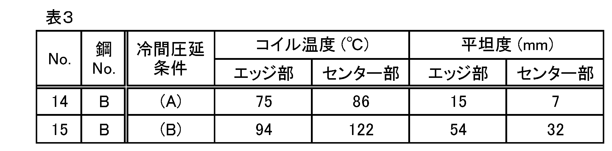
- Example 2 Using steel B in Table 1, hot rolling was performed at a finish hot rolling temperature: 850 ° C. and a winding temperature: 570 ° C. to produce a steel plate having a thickness of 2.5 mm. The average cooling rate from finish rolling to winding is 35 ° C./sec. This steel plate was cold-rolled to a plate thickness of 1.0 mm by the following two cold rolling methods.
- the coil surface temperature was measured for each pass.
- the measurement position was 50 mm from the center and edge in the width direction at the center in the coil longitudinal direction.
- the flatness of the cold-rolled steel sheet having a thickness of 1.0 mm after rolling was measured at the center part and the edge part.
- the flatness was evaluated by measuring the height of a peak between 2000 mm in the longitudinal direction of the coil as a specified length. The results are shown in Table 3.
Landscapes
- Chemical & Material Sciences (AREA)
- Engineering & Computer Science (AREA)
- Mechanical Engineering (AREA)
- Materials Engineering (AREA)
- Metallurgy (AREA)
- Organic Chemistry (AREA)
- Crystallography & Structural Chemistry (AREA)
- Thermal Sciences (AREA)
- Physics & Mathematics (AREA)
- General Engineering & Computer Science (AREA)
- Heat Treatment Of Sheet Steel (AREA)
- Heat Treatment Of Steel (AREA)
- Metal Rolling (AREA)
Abstract
Description
(i)「強度(硬さ) vs. 延性および靱性」バランス
スチールベルトは、コンベアの用途に応じて適度な張力を負荷して使用されるので、負荷される張力下で変形しない程度の強度が必要である。また、使用中に「扱い疵」がつかない程度の表面硬さが要求される。一方、スチールベルト製造時には鋼材に引張変形を加えることにより形状修正が行われる。その際、強度が高すぎると延性(塑性変形能)が不足し形状修正ができない。また、使用中の靱性を確保するためにも適度な延性が必要である。
(ii)疲労強度
ベルトコンベアは使用中に繰り返し曲げ応力が負荷されるので、疲労強度が高いことが必要である。
(iii)溶接性
鋼板をエンドレスのベルト形状にする際、溶接が施される。また、スチールベルトの補修時にも溶接が施されることがある。したがって、良好な溶接性を有することが必要である。
(iv)平坦度
前述の通り、カーボンスチールベルトの代表用途はオーブンなどのコンベアベルトであり、使用時には平坦な形状が求められる。素材コイルから、コンベアベルトを作製する際に形状修正を行い、使用時には張力を加えて平坦度を高める対応が取られるが、素材コイルには優れた平坦度が求められる。
i)(約0.65%C鋼の熱延または冷延鋼板)→焼入れ・焼戻し
ii)(約0.65%C鋼の熱延または冷延鋼板)→パテンティング→冷延→ブルーイング
上記項の成分元素のうち、V、Ti、Nb、Bは任意添加元素である。
圧下率(%)=(h0-h1)/h0×100 …(1)
h0:その圧延パス前の板厚(mm)
h1:その圧延パス後の板厚(mm)
また、総圧延率は下記(2)式により表される。
総圧延率(%)=(H0-H1)/H0×100 …(2)
H0:圧延開始前(初回パス前)の板厚(mm)
H1:圧延終了後(最終パス後)の板厚(mm)
[A]図1に示す試験片の長手方向(圧延方向に一致)に、室温で引張速度0.3mm/minの引張試験を行って、荷重-伸び曲線から最大荷重を求め、その最大荷重を初期断面積(45mm×板厚)で除した値(単位:MPa)を亀裂伝播抵抗とする。
「室温」はJIS Z2241:2011(金属材料引張試験方法)に記載の通り10~35℃を意味する。
(1)初析フェライト+パーライトの組織を有する鋼板を加工した場合、加工硬化した初析フェライト相と加工硬化したパーライト組織とでは、パーライト組織の方が亀裂伝播抵抗が大きい。昨今のニーズに適した耐久性の高いスチールベルトを得るには鋼板中のパーライト組織の量を70%体積以上とする必要があり、90体積%以上とすることがより効果的である。
(2)冷延工程においてパーライト組織中にはミクロな割れが導入され、これが、疲労亀裂の起点になりうる。そのミクロな割れはセメンタイト・ラメラに発生する。
(3)パーライト組織中のセメンタイト・ラメラが薄いほど冷延でのミクロな割れは生じにくい。特に、パーライト組織中のセメンタイトの体積率が15%以下であるとき、セメンタイト・ラメラは割れにくくなり、鋼板の亀裂伝播抵抗は大幅に向上する。
(4)スチールベルトとして使用される状態の鋼板において、初析フェライト相の板厚方向の厚さが5μm以下であることが高い亀裂伝播抵抗を得る上で効果的である。
(a)冷間圧延における1パスあたりの圧下率が高ければ加工発熱量も大きくコイル温度が上昇するのであるが、鋼板の温度が110℃を超えると動的ひずみ時効が起るようになり、冷間圧延時の変形抵抗が急激に上昇する。
(b)加工による熱量は、ロールへの熱伝導、圧延油による系外への放出があるため、コイルの幅方向中央部の温度上昇は幅方向端部(エッジ)より大きい。
(d)加工発熱が大きくコイル温度が上昇する場合、幅方向中央部がまず110℃を超えて、動的ひずみ時効を起こし始める。このため、中央部で変形抵抗が高く、エッジで変形抵抗が低い状況が生じる。その結果、幅方向で変形量(伸び)が不均一になり、平坦度が劣化する。
(e)従って、鋼板の幅方向(圧延方向に対して直角方向)の中央部の材料温度が110℃を超えないように冷間圧延1パス当りの圧下率をコントロールすることが、幅方向の変形抵抗の不均一さを抑制するうえで極めて有効である。幅方向中央部の材料温度を100℃以下にコントロールすることがより効果的である。
本発明は、これらの知見に基づき完成したものである。以下、本発明を特定する事項について説明する。
Cは、パーライト主体の金属組織を得るために重要な元素である。すなわち、C含有量は、パーライトの生成量および形態に大きな影響を及ぼす。C量が少ないと、熱延鋼板中におけるパーライト組織の体積率が減少し、スチールベルトに使用される状態の鋼板においてパーライト組織の量を十分に確保することが困難になる。また、初析フェライトが増加することにより冷間圧延での加工硬化能が低下するので、目標の強度レベルを得るには冷間圧延の総圧延率が過大となる恐れがある。さらに、初析フェライト相の加工歪が過大となることに加え、延性、靱性に有利なパーライト組織が少ないため、延性、靱性の低下を招く。種々検討の結果、本発明ではC含有量を0.60質量%以上好ましくは0.60質量%を超える量に規定する。
以上のことから、本発明ではC含有量を0.60~0.80質量%の範囲、より好ましくは0.60質量%を超え0.80質量%以下の範囲に厳密にコントロールする必要がある。
Sは、鋼中でMnSを形成し亀裂の起点となりやすく、疲労特性の低下を招く。実質的に問題にならない範囲として、本発明では0.010質量%までのS含有を許容する。過度の脱Sは製鋼負荷を増大させるので、S含有量は通常0.001~0.010質量%の範囲とすればよい。
本発明に従えば、スチールベルトとして使用される状態の鋼板において、金属組織中に占めるパーライト組織の体積率を70%以上、好ましくは90%以上とすることができる。パーライト以外の残部は初析フェライト相である。パーライトを含む金属組織の熱延鋼板を冷間圧延すると、パーライト組織のラメラが冷延方向に配向しながら、ラメラ間隔が微細化する。そして、圧延方向に揃った微細ラメラが形成されることによってパーライト組織は加工硬化する。ラメラが圧延方向に揃った微細なパーライト組織は、強度が高いにもかかわらず靱性低下が小さい。また、さらに時効処理を行うと高強度を保ったままで延性・靱性が一層改善される。
昨今のスチールベルトに求められる耐久性・信頼性を確保するためには、それに使用する鋼板の具体的な機械的性質として、室温における圧延方向の引張強さが1100MPa以上好ましくは1300MPa以上であり、かつ下記[A]の定義に従う亀裂伝播抵抗が600MPa以上である特性を挙げることができる。
[A]図1に示す試験片の長手方向(圧延方向に一致)に、室温で引張速度0.3mm/minの引張試験を行って、荷重-伸び曲線から最大荷重を求め、その最大荷重を初期断面積(45mm×板厚)で除した値(単位:MPa)を亀裂伝播抵抗とする。
また、室温における圧延方向の全伸びが5.0%以上であることが好ましい。
〔熱間圧延〕
熱間圧延では、パーライト変態の過冷度を大きくするために、仕上熱延後の冷却速度を大きくすることが望ましい。具体的には、先に説明した成分組成を有する鋼を用いた場合、仕上熱延温度(熱間圧延最終パス圧延温度)を800~900℃とし、その後、巻取までの間の平均冷却速度が20℃/sec以上となるように急冷し、450~650℃で巻き取る方法が好適に採用できる。この方法は、上述したように初析フェライト相の生成量を抑制する効果や粒径を微細化する効果もある。
本発明では、上述のように「強度 vs. 延性および靱性」バランスと耐久性を高レベルで実現できる金属組織を明らかにした。製造工程についても種々検討したところ、このような金属組織を呈する鋼板は、従来のような恒温変態処理を行わず、熱延鋼板を直接冷間圧延する方法により製造することが可能である。ただし、ベルトコンベア用スチールベルトなど平坦度が要求されるスチールベルトを製造する場合には、平坦度の高い素材鋼板を得ておくことが極めて有利である。平坦度の高い鋼板を得るためには、上記(a)~(e)で説明した通り、冷間圧延時の温度上昇に伴う動的ひずみ時効を防止することが極めて有効であることがわかった。鋼板の圧延方向に対して直角方向(幅方向)中央部における材料表面温度が110℃を超えると、幅方向中央部で動的ひずみ時効が起こりやすくなり、比較的温度上昇の少ない幅方向端部(エッジ部)近傍と幅方向中央部との特性にバラツキが生じ、それが冷延鋼板の平坦度を劣化させる要因となる。幅方向中央部の材料表面温度が100℃以下となるようにコントロールすることがより効果的である。
冷間圧延後には、200~500℃で0.5~30h保持する時効処理を施す。
調質圧延は必要に応じて施すことができる。時効処理後、調質圧延を施す場合には、10%以下の圧下率で行うことが望ましい。
表1に示す成分組成の鋼を溶製し、以下の条件で熱間圧延→冷間圧延→時効処理→調質圧延を行い、板厚1.0mmの鋼板を製造した。熱間圧延条件は表2中に記載した。仕上熱延後、巻取までの平均冷却速度は、表2のNo.3は10℃/sec、No.4は60℃/sec、それ以外は30℃/secとした。熱延鋼板の板厚は2.0~5.0mmの範囲とした。冷間圧延は、熱延鋼板を酸洗したのち、板厚1.0~1.1mmまで圧延した。冷間圧延1パス当たりの圧下率は最大7%とし、冷間圧延パス数は8~25回であった。冷間圧延の総圧延率はいずれの例も40%以上であり、表2のNo.12は約80%とした。時効処理は、400℃×15hの条件で行った。調質圧延は、圧延率10%以下で行った。なお、表2のNo.10は冷間圧延にて板厚1.0mmとし、調質圧延を省略した(調質圧延率0%)。

〔パーライト組織の観察〕
鋼板の圧延方向と板厚方向を含む断面を電解研磨したのちエッチングしたサンプルを用意した。光学顕微鏡を用いて撮影したサンプル表面の画像をもとに画像処理装置にてパーライト組織の体積率を求めた。
上記と同様のサンプルについて、走査電子顕微鏡を用いて、圧延方向に伸びた10個の初析フェライト相の板厚方向の最大厚さを測定し、その平均値を「初析フェライト相の板厚方向厚さ」とした。
鋼板の圧延方向と板厚方向を含む断面におけるビッカース硬さを測定した。コンベアとして使用されるスチールベルト用鋼板としては310HV以上の硬さレベルが要求されるが、380HV以上であることがより好ましい。
圧延方向に平行なJIS 5号引張試験片を用い、室温にて引張速度10mm/minで引張試験を行った。コンベアとして使用されるスチールベルト用鋼板コンベア用スチールベルトとしては引張強さ1100MPa以上、全伸び5%以上の特性が望まれるが、特に引張強さは1300MPa以上であることが好ましい。
図1に示す試験片を用いて、前記[A]で定義した方法にて亀裂伝播抵抗を求めた。その値が600MPa以上のものを良好と判定した。これらの結果を表2に示す。

表1の鋼Bを用いて、仕上熱延温度:850℃、巻取温度:570℃で熱間圧延を行い、板厚2.5mmの鋼板を製造した。仕上圧延後、巻取までの平均冷却速度は35℃/secとした。この鋼板を次の2通りの冷間圧延方法にて板厚1.0mmまで冷間圧延した。
(A)圧延速度:200m/min、圧延パス数:15パス、各パスの圧下率:最大7%、総圧延率:60%(本発明例)
(B)圧延速度:200m/min、圧延パス数:9パス、各パスの圧下率:最大13%、総圧延率:60%(比較例)
Claims (9)
- 質量%で、C:0.60~0.80%、Si:1.0%以下、Mn:0.10~1.0%、P:0.020%以下、S:0.010%以下、Cr:0.1~1.0%、V:0~0.5%、Ti:0~0.1%、Nb:0~0.1%、B:0~0.01%、残部がFeおよび不可避的不純物からなる化学組成を有する鋼のスラブに対して、仕上熱延温度:800~900℃、仕上熱延後、巻取までの平均冷却速度:20℃/sec以上、巻取温度:450~650℃の条件で熱間圧延を施した後、熱処理を行わずに、1パス当たり12%未満の圧下率にて総圧延率40%以上の冷間圧延を施し、次いで200~500℃で0.5~30h保持する時効処理を施すスチールベルト用鋼板の製造法。
- 質量%で、C:0.60~0.80%、Si:1.0%以下、Mn:0.10~1.0%、P:0.020%以下、S:0.010%以下、Cr:0.1~1.0%、V:0~0.5%、Ti:0~0.1%、Nb:0~0.1%、B:0~0.01%、残部がFeおよび不可避的不純物からなる化学組成を有する鋼のスラブに対して、仕上熱延温度:800~900℃、仕上熱延後、巻取までの平均冷却速度:20℃/sec以上、巻取温度:450~650℃の条件で熱間圧延を施した後、熱処理を行わずに、1パス当たり12%未満の圧下率にて総圧延率40%以上の冷間圧延を施し、次いで200~500℃で0.5~30h保持する時効処理を施すことにより、金属組織中に占めるパーライト組織の体積率が70%以上、圧延方向の引張強さが1100MPa以上、下記[A]の定義に従う亀裂伝播抵抗が600MPa以上である鋼板を製造する、スチールベルト用鋼板の製造法。
[A]図1に示す試験片の長手方向(圧延方向に一致)に、室温で引張速度0.3mm/minの引張試験を行って、荷重-伸び曲線から最大荷重を求め、その最大荷重を初期断面積(45mm×板厚)で除した値(単位:MPa)を亀裂伝播抵抗とする。 - 質量%で、C:0.60%超え0.80%以下、Si:0.10~1.00%、Mn:0.10~1.00%、P:0.002~0.020%、S:0.001~0.010%、Cr:0.10~1.00%、V:0~0.50%、Ti:0~0.10%、Nb:0~0.10%、B:0~0.010%、残部がFeおよび不可避的不純物からなる化学組成を有する鋼のスラブに対して、仕上熱延温度:800~900℃、仕上熱延後、巻取までの平均冷却速度:25℃/sec以上、巻取温度:450~650℃の条件で熱間圧延を施した後、熱処理を行わずに、1パス当たり12%未満の圧下率にて総圧延率40%以上の冷間圧延を施し、次いで200~500℃で0.5~30h保持する時効処理を施すスチールベルト用鋼板の製造法。
- 質量%で、C:0.60%超え0.80%以下、Si:0.10~1.00%、Mn:0.10~1.00%、P:0.002~0.020%、S:0.001~0.010%、Cr:0.10~1.00%、V:0~0.50%、Ti:0~0.10%、Nb:0~0.10%、B:0~0.010%、残部がFeおよび不可避的不純物からなる化学組成を有する鋼のスラブに対して、仕上熱延温度:800~900℃、仕上熱延後、巻取までの平均冷却速度:25℃/sec以上、巻取温度:450~650℃の条件で熱間圧延を施した後、熱処理を行わずに、1パス当たり12%未満の圧下率にて総圧延率40%以上の冷間圧延を施し、次いで200~500℃で0.5~30h保持する時効処理を施すことにより、金属組織中に占めるパーライト組織の体積率が90%以上、圧延方向の引張強さが1300MPa以上、下記[A]の定義に従う亀裂伝播抵抗が600MPa以上である鋼板を製造する、スチールベルト用鋼板の製造法。
[A]図1に示す試験片の長手方向(圧延方向に一致)に、室温で引張速度0.3mm/minの引張試験を行って、荷重-伸び曲線から最大荷重を求め、その最大荷重を初期断面積(45mm×板厚)で除した値(単位:MPa)を亀裂伝播抵抗とする。 - 前記冷間圧延において1パス当たりの圧下率を10%以下として総圧延率を40%以上とする請求項1~4のいずれか1項に記載のスチールベルト用鋼板の製造法。
- 前記冷間圧延において各圧延パスでの材料温度を110℃以下に維持する請求項1~5のいずれか1項に記載のスチールベルト用鋼板の製造法。
- 時効処理後に圧延率10%以下の調質圧延を行う請求項1~6のいずれか1項に記載のスチールベルト用鋼板の製造法。
- 質量%で、C:0.60%超え0.80%以下、Si:0.10~1.00%、Mn:0.10~1.00%、P:0.002~0.020%、S:0.001~0.010%、Cr:0.10~1.00%、V:0~0.50%、Ti:0~0.10%、Nb:0~0.10%、B:0~0.010%、残部がFeおよび不可避的不純物からなる化学組成を有し、パーライト組織が90体積%以上を占め、残部が初析フェライト相である金属組織を有し、圧延方向の引張強さが1300MPa以上、下記[A]の定義に従う亀裂伝播抵抗が600MPa以上であるスチールベルト用鋼板。
[A]図1に示す試験片の長手方向(圧延方向に一致)に、室温で引張速度0.3mm/minの引張試験を行って、荷重-伸び曲線から最大荷重を求め、その最大荷重を初期断面積(45mm×板厚)で除した値(単位:MPa)を亀裂伝播抵抗とする。 - 請求項8に記載の鋼板を溶接によりエンドレスベルトにしたスチールベルト。
Priority Applications (6)
| Application Number | Priority Date | Filing Date | Title |
|---|---|---|---|
| US14/895,511 US20160131222A1 (en) | 2013-06-05 | 2014-06-05 | Steel sheet for steel belt and process for manufacturing same, and steel belt |
| EP14807676.3A EP3006578B1 (en) | 2013-06-05 | 2014-06-05 | Steel sheet for steel belt and process for manufacturing same, and steel belt |
| CN201480032035.1A CN105378119B (zh) | 2013-06-05 | 2014-06-05 | 钢带用钢板及其制造方法以及钢带 |
| JP2015521477A JP6129311B2 (ja) | 2013-06-05 | 2014-06-05 | スチールベルト用鋼板およびその製造法並びにスチールベルト |
| KR1020157036221A KR102291678B1 (ko) | 2013-06-05 | 2014-06-05 | 스틸 벨트용 강판 및 그 제조 방법 및 스틸 벨트 |
| US16/244,258 US11261935B2 (en) | 2013-06-05 | 2019-01-10 | Process for manufacturing a steel sheet, and steel belt made therefrom |
Applications Claiming Priority (2)
| Application Number | Priority Date | Filing Date | Title |
|---|---|---|---|
| JP2013119156 | 2013-06-05 | ||
| JP2013-119156 | 2013-06-05 |
Related Child Applications (2)
| Application Number | Title | Priority Date | Filing Date |
|---|---|---|---|
| US14/895,511 A-371-Of-International US20160131222A1 (en) | 2013-06-05 | 2014-06-05 | Steel sheet for steel belt and process for manufacturing same, and steel belt |
| US16/244,258 Division US11261935B2 (en) | 2013-06-05 | 2019-01-10 | Process for manufacturing a steel sheet, and steel belt made therefrom |
Publications (1)
| Publication Number | Publication Date |
|---|---|
| WO2014196586A1 true WO2014196586A1 (ja) | 2014-12-11 |
Family
ID=52008218
Family Applications (1)
| Application Number | Title | Priority Date | Filing Date |
|---|---|---|---|
| PCT/JP2014/064921 WO2014196586A1 (ja) | 2013-06-05 | 2014-06-05 | スチールベルト用鋼板およびその製造法並びにスチールベルト |
Country Status (6)
| Country | Link |
|---|---|
| US (2) | US20160131222A1 (ja) |
| EP (1) | EP3006578B1 (ja) |
| JP (1) | JP6129311B2 (ja) |
| KR (1) | KR102291678B1 (ja) |
| CN (1) | CN105378119B (ja) |
| WO (1) | WO2014196586A1 (ja) |
Cited By (3)
| Publication number | Priority date | Publication date | Assignee | Title |
|---|---|---|---|---|
| JP2020509190A (ja) * | 2016-12-20 | 2020-03-26 | ポスコPosco | 高温伸び特性に優れた高強度鋼板、温間プレス成形部材、及びそれらの製造方法 |
| WO2020179737A1 (ja) * | 2019-03-06 | 2020-09-10 | 日本製鉄株式会社 | 熱間圧延鋼板およびその製造方法 |
| JP7400707B2 (ja) | 2020-11-30 | 2023-12-19 | Jfeスチール株式会社 | 鋼板及びその製造方法 |
Families Citing this family (6)
| Publication number | Priority date | Publication date | Assignee | Title |
|---|---|---|---|---|
| WO2017050857A1 (de) | 2015-09-25 | 2017-03-30 | Inventio Ag | Überwachungseinrichtung für eine aufzugsanlage |
| NL1041998B1 (en) * | 2016-07-27 | 2018-02-01 | Bosch Gmbh Robert | Flexible steel ring made from maraging steel and provided with a nitrided surface layer |
| KR101849760B1 (ko) * | 2016-09-28 | 2018-04-17 | 주식회사 포스코 | 고탄소 강판 및 이의 제조방법 |
| CN109941698B (zh) * | 2019-04-03 | 2020-08-18 | 武汉科技大学 | 一种考虑疲劳破坏的带式输送机速度调节方法 |
| KR102400252B1 (ko) | 2020-01-07 | 2022-05-19 | 장활석 | 스틸벨트형 이송컨베이어 |
| CN114888115A (zh) * | 2022-04-28 | 2022-08-12 | 湖南华菱湘潭钢铁有限公司 | 一种热轧冷镦钢盘条的生产方法 |
Citations (5)
| Publication number | Priority date | Publication date | Assignee | Title |
|---|---|---|---|---|
| JPS57101615A (en) | 1980-12-18 | 1982-06-24 | Nisshin Steel Co Ltd | Manufacture of steel strip for steel belt |
| JP2003286542A (ja) * | 2002-03-29 | 2003-10-10 | Nisshin Steel Co Ltd | 亀裂伝播抵抗に優れたスチールベルト用鋼板およびその製造法 |
| JP2009024233A (ja) * | 2007-07-20 | 2009-02-05 | Nisshin Steel Co Ltd | 焼入れ性、疲労特性、靭性に優れた高炭素鋼板及びその製造方法 |
| JP2010138488A (ja) * | 2008-11-17 | 2010-06-24 | Jfe Steel Corp | 引張強さが1500MPa以上の高強度鋼板およびその製造方法 |
| JP2013007084A (ja) * | 2011-06-23 | 2013-01-10 | Nippon Steel & Sumitomo Metal Corp | 高強度、高疲労強度の薄鋼帯板と無端状鋼帯及びその製造方法 |
Family Cites Families (8)
| Publication number | Priority date | Publication date | Assignee | Title |
|---|---|---|---|---|
| JPS4738616Y1 (ja) | 1968-01-18 | 1972-11-22 | ||
| DE58904914D1 (de) * | 1988-12-30 | 1993-08-19 | Alusuisse Lonza Services Ag | Verfahren und vorrichtung zum regeln der planheit eines kaltgewalzten metallbandes. |
| JPH09170017A (ja) * | 1995-10-18 | 1997-06-30 | Nisshin Steel Co Ltd | 高強度高靭性鋼板の製造方法 |
| JP4210362B2 (ja) * | 1998-03-24 | 2009-01-14 | 日新製鋼株式会社 | 疲労特性に優れた高強度鋼の製造方法 |
| KR101150365B1 (ko) * | 2008-08-14 | 2012-06-08 | 주식회사 포스코 | 고탄소 열연강판 및 그 제조방법 |
| KR101128942B1 (ko) * | 2008-12-24 | 2012-03-27 | 주식회사 포스코 | 열처리 특성이 우수한 미세구상화 강판 및 그 제조방법 |
| JP5287770B2 (ja) * | 2010-03-09 | 2013-09-11 | Jfeスチール株式会社 | 高強度鋼板およびその製造方法 |
| KR101356773B1 (ko) * | 2010-09-16 | 2014-01-28 | 주식회사 포스코 | 고탄소 열연강판, 냉연강판 및 그 제조방법 |
-
2014
- 2014-06-05 KR KR1020157036221A patent/KR102291678B1/ko active IP Right Grant
- 2014-06-05 WO PCT/JP2014/064921 patent/WO2014196586A1/ja active Application Filing
- 2014-06-05 EP EP14807676.3A patent/EP3006578B1/en active Active
- 2014-06-05 JP JP2015521477A patent/JP6129311B2/ja active Active
- 2014-06-05 CN CN201480032035.1A patent/CN105378119B/zh active Active
- 2014-06-05 US US14/895,511 patent/US20160131222A1/en not_active Abandoned
-
2019
- 2019-01-10 US US16/244,258 patent/US11261935B2/en active Active
Patent Citations (6)
| Publication number | Priority date | Publication date | Assignee | Title |
|---|---|---|---|---|
| JPS57101615A (en) | 1980-12-18 | 1982-06-24 | Nisshin Steel Co Ltd | Manufacture of steel strip for steel belt |
| JP2003286542A (ja) * | 2002-03-29 | 2003-10-10 | Nisshin Steel Co Ltd | 亀裂伝播抵抗に優れたスチールベルト用鋼板およびその製造法 |
| JP3964246B2 (ja) | 2002-03-29 | 2007-08-22 | 日新製鋼株式会社 | 亀裂伝播抵抗に優れたスチールベルト用鋼板およびその製造法 |
| JP2009024233A (ja) * | 2007-07-20 | 2009-02-05 | Nisshin Steel Co Ltd | 焼入れ性、疲労特性、靭性に優れた高炭素鋼板及びその製造方法 |
| JP2010138488A (ja) * | 2008-11-17 | 2010-06-24 | Jfe Steel Corp | 引張強さが1500MPa以上の高強度鋼板およびその製造方法 |
| JP2013007084A (ja) * | 2011-06-23 | 2013-01-10 | Nippon Steel & Sumitomo Metal Corp | 高強度、高疲労強度の薄鋼帯板と無端状鋼帯及びその製造方法 |
Non-Patent Citations (1)
| Title |
|---|
| See also references of EP3006578A4 |
Cited By (8)
| Publication number | Priority date | Publication date | Assignee | Title |
|---|---|---|---|---|
| JP2020509190A (ja) * | 2016-12-20 | 2020-03-26 | ポスコPosco | 高温伸び特性に優れた高強度鋼板、温間プレス成形部材、及びそれらの製造方法 |
| US11680305B2 (en) | 2016-12-20 | 2023-06-20 | Posco Co., Ltd | High strength steel sheet having excellent high-temperature elongation characteristic, warm-pressed member, and manufacturing methods for the same |
| WO2020179737A1 (ja) * | 2019-03-06 | 2020-09-10 | 日本製鉄株式会社 | 熱間圧延鋼板およびその製造方法 |
| KR20210120087A (ko) * | 2019-03-06 | 2021-10-06 | 닛폰세이테츠 가부시키가이샤 | 열간 압연 강판 및 그의 제조 방법 |
| JPWO2020179737A1 (ja) * | 2019-03-06 | 2021-10-21 | 日本製鉄株式会社 | 熱間圧延鋼板およびその製造方法 |
| JP7131687B2 (ja) | 2019-03-06 | 2022-09-06 | 日本製鉄株式会社 | 熱間圧延鋼板およびその製造方法 |
| KR102649506B1 (ko) | 2019-03-06 | 2024-03-22 | 닛폰세이테츠 가부시키가이샤 | 열간 압연 강판 및 그의 제조 방법 |
| JP7400707B2 (ja) | 2020-11-30 | 2023-12-19 | Jfeスチール株式会社 | 鋼板及びその製造方法 |
Also Published As
| Publication number | Publication date |
|---|---|
| US11261935B2 (en) | 2022-03-01 |
| CN105378119A (zh) | 2016-03-02 |
| JPWO2014196586A1 (ja) | 2017-02-23 |
| EP3006578A1 (en) | 2016-04-13 |
| US20190154111A1 (en) | 2019-05-23 |
| CN105378119B (zh) | 2019-03-22 |
| EP3006578A4 (en) | 2017-03-29 |
| KR20160018577A (ko) | 2016-02-17 |
| KR102291678B1 (ko) | 2021-08-23 |
| JP6129311B2 (ja) | 2017-05-17 |
| EP3006578B1 (en) | 2019-05-15 |
| US20160131222A1 (en) | 2016-05-12 |
Similar Documents
| Publication | Publication Date | Title |
|---|---|---|
| JP6129311B2 (ja) | スチールベルト用鋼板およびその製造法並びにスチールベルト | |
| JP5040197B2 (ja) | 加工性に優れ、かつ熱処理後の強度靭性に優れた熱延薄鋼板およびその製造方法 | |
| JP5315790B2 (ja) | 耐遅れ破壊特性に優れた高強度pc鋼線 | |
| US20100212786A1 (en) | High-Strength Steel Wire Excellent In Ductility and Method of Manufacturing the Same | |
| JP5040475B2 (ja) | 加工性に優れ、かつ熱処理後の強度靭性に優れた厚肉熱延鋼板およびその製造方法 | |
| US20100263772A1 (en) | Wire rods having superior strength and ductility for drawing and method for manufacturing the same | |
| WO2016194272A1 (ja) | 高強度冷延鋼板、高強度めっき鋼板及びこれらの製造方法 | |
| JP5892267B2 (ja) | 電縫鋼管 | |
| WO2020039696A1 (ja) | 高強度鋼板及びその製造方法 | |
| KR101733513B1 (ko) | 질화 처리용 강판 및 그의 제조 방법 | |
| JP3964246B2 (ja) | 亀裂伝播抵抗に優れたスチールベルト用鋼板およびその製造法 | |
| JP2010229469A (ja) | 冷間加工特性に優れる高強度線材及びその製造方法 | |
| JP5151354B2 (ja) | 高張力冷延鋼板及び高張力冷延鋼板の製造方法 | |
| JP2008208450A (ja) | 強度延性バランスに優れた高強度極細鋼線の製造方法 | |
| JP6193842B2 (ja) | 軸受用鋼線材 | |
| JP6796472B2 (ja) | 中空部材及びその製造方法 | |
| KR101921595B1 (ko) | 리징성 및 표면품질이 우수한 페라이트계 스테인리스강 및 그 제조방법 | |
| JP6342056B2 (ja) | フェライト系ステンレス鋼板 | |
| JP3840376B2 (ja) | 疲労強度および延性に優れた硬引き線用鋼材および硬引き伸線材 | |
| WO2017169837A1 (ja) | 高強度冷延鋼板および高強度溶融亜鉛めっき鋼板並びにそれらの製造方法 | |
| US10752969B2 (en) | Steel for suspension spring and method of manufacturing same | |
| JP5157417B2 (ja) | 鋼板およびその製造方法 | |
| JPWO2020039697A1 (ja) | 高強度鋼板及びその製造方法 | |
| JP2012229455A (ja) | 強度、延性及び衝撃エネルギー吸収能に優れた高強度鋼材並びにその製造方法 |
Legal Events
| Date | Code | Title | Description |
|---|---|---|---|
| 121 | Ep: the epo has been informed by wipo that ep was designated in this application |
Ref document number: 14807676 Country of ref document: EP Kind code of ref document: A1 |
|
| ENP | Entry into the national phase |
Ref document number: 2015521477 Country of ref document: JP Kind code of ref document: A |
|
| WWE | Wipo information: entry into national phase |
Ref document number: 14895511 Country of ref document: US Ref document number: 2014807676 Country of ref document: EP |
|
| NENP | Non-entry into the national phase |
Ref country code: DE |
|
| ENP | Entry into the national phase |
Ref document number: 20157036221 Country of ref document: KR Kind code of ref document: A |