WO2014196358A1 - 印刷版現像液の処理方法および印刷版現像液の処理システム - Google Patents
印刷版現像液の処理方法および印刷版現像液の処理システム Download PDFInfo
- Publication number
- WO2014196358A1 WO2014196358A1 PCT/JP2014/063443 JP2014063443W WO2014196358A1 WO 2014196358 A1 WO2014196358 A1 WO 2014196358A1 JP 2014063443 W JP2014063443 W JP 2014063443W WO 2014196358 A1 WO2014196358 A1 WO 2014196358A1
- Authority
- WO
- WIPO (PCT)
- Prior art keywords
- waste liquid
- packed bed
- developer
- printing plate
- packed
- Prior art date
- Legal status (The legal status is an assumption and is not a legal conclusion. Google has not performed a legal analysis and makes no representation as to the accuracy of the status listed.)
- Ceased
Links
Images

Classifications
-
- G—PHYSICS
- G03—PHOTOGRAPHY; CINEMATOGRAPHY; ANALOGOUS TECHNIQUES USING WAVES OTHER THAN OPTICAL WAVES; ELECTROGRAPHY; HOLOGRAPHY
- G03G—ELECTROGRAPHY; ELECTROPHOTOGRAPHY; MAGNETOGRAPHY
- G03G21/00—Arrangements not provided for by groups G03G13/00 - G03G19/00, e.g. cleaning, elimination of residual charge
- G03G21/10—Collecting or recycling waste developer
-
- G—PHYSICS
- G03—PHOTOGRAPHY; CINEMATOGRAPHY; ANALOGOUS TECHNIQUES USING WAVES OTHER THAN OPTICAL WAVES; ELECTROGRAPHY; HOLOGRAPHY
- G03F—PHOTOMECHANICAL PRODUCTION OF TEXTURED OR PATTERNED SURFACES, e.g. FOR PRINTING, FOR PROCESSING OF SEMICONDUCTOR DEVICES; MATERIALS THEREFOR; ORIGINALS THEREFOR; APPARATUS SPECIALLY ADAPTED THEREFOR
- G03F7/00—Photomechanical, e.g. photolithographic, production of textured or patterned surfaces, e.g. printing surfaces; Materials therefor, e.g. comprising photoresists; Apparatus specially adapted therefor
- G03F7/26—Processing photosensitive materials; Apparatus therefor
- G03F7/30—Imagewise removal using liquid means
- G03F7/3092—Recovery of material; Waste processing
-
- B—PERFORMING OPERATIONS; TRANSPORTING
- B01—PHYSICAL OR CHEMICAL PROCESSES OR APPARATUS IN GENERAL
- B01D—SEPARATION
- B01D15/00—Separating processes involving the treatment of liquids with solid sorbents; Apparatus therefor
- B01D15/08—Selective adsorption, e.g. chromatography
- B01D15/10—Selective adsorption, e.g. chromatography characterised by constructional or operational features
- B01D15/20—Selective adsorption, e.g. chromatography characterised by constructional or operational features relating to the conditioning of the sorbent material
-
- B—PERFORMING OPERATIONS; TRANSPORTING
- B01—PHYSICAL OR CHEMICAL PROCESSES OR APPARATUS IN GENERAL
- B01D—SEPARATION
- B01D15/00—Separating processes involving the treatment of liquids with solid sorbents; Apparatus therefor
- B01D15/08—Selective adsorption, e.g. chromatography
- B01D15/10—Selective adsorption, e.g. chromatography characterised by constructional or operational features
- B01D15/20—Selective adsorption, e.g. chromatography characterised by constructional or operational features relating to the conditioning of the sorbent material
- B01D15/203—Equilibration or regeneration
Definitions
- the present invention relates to a processing method for a printing plate developer and a processing system for a printing plate developer, and more specifically, printing plate development to be performed on a development waste solution containing a polymer component generated in a development process in which development is performed using an aqueous developer.
- the present invention relates to a liquid processing method and a printing plate developer processing system.
- An original plate of a printing plate includes a photosensitive layer made of a photosensitive resin composition on a substrate such as a PET resin.
- the printing plate is formed by irradiating the photosensitive layer with ultraviolet rays through a negative film in close contact with the photosensitive layer and removing the uncured portion to form a relief image.
- developing methods for printing plates For example, in a developing method in which development is performed using an aqueous developer containing water as a main component, the printing plate is immersed in an aqueous developer, and an aqueous solution is obtained with a brush. Development is performed by rubbing an uncured portion into the developer.
- the developer waste liquid contains a scraped polymer component, and when reused as it is as a developer, a new printing plate is soiled, so that the developer waste liquid may be discarded.
- this since this generates a large amount of waste, there has been a demand for improvement from the environmental aspect.
- Patent Document 1 proposes a method of removing aggregates in a developing waste solution using a filter and reusing the filtrate as a developing solution.
- Patent Document 2 proposes a method of removing a polymer component aggregated by adding a flocculant to a development waste liquid from the development waste liquid.
- the development waste liquid In the development method in which development is performed using an aqueous developer, all polymer components contained in the development waste liquid are not aggregated, and some of the polymer components are dissolved in the development waste liquid.
- the uncured portion of the photosensitive layer may contain additives in addition to the polymer component, and there are additives that dissolve in the development waste liquid.
- an aggregating agent if used, there is a possibility that the aggregating agent may remain in the developing waste liquid. If this is reused as a developing solution, the polymer component rubbed out during development may aggregate and adhere to a printing plate, brush, or the like. . In addition, it is difficult to agglomerate the water-soluble polymer dissolved in the developing waste liquid using a flocculant.
- the present invention has been made in view of the above circumstances, and a problem to be solved by the present invention is that a printing plate developer that enables reuse of development waste liquid by removing components dissolved in the development waste liquid. And a processing system for a printing plate developer.
- the printing plate developer processing method performs development using an aqueous developer containing water as a main component on a printing plate material having a photosensitive resin layer on which a latent image is formed.
- the gist is to pass a developer waste solution containing a polymer component generated in the development step through a packed bed filled with activated carbon, and return the passing solution to the aqueous developer supply unit of the developing machine to be reused as an aqueous developer.
- the cleaning process of cleaning the activated carbon in the packed bed by passing water vapor through the packed bed through which the developing waste liquid is passed is alternately performed by switching to the waste liquid process in which the developing waste liquid is passed through the packed bed filled with activated carbon.
- the printing plate developer processing system is generated in a developing process in which a printing plate material having a photosensitive resin layer on which a latent image is formed is developed using an aqueous developer containing water as a main component.
- a waste liquid collecting unit that collects a developing waste liquid containing a polymer component, a packed bed that is connected to the waste liquid collecting unit and is filled with activated carbon for passing the developing waste liquid, and is connected to the packed bed and passes through the packed bed.
- a passage liquid returning section that returns the passage liquid to the aqueous developer supply section in the developing machine.
- a cleaning unit connected to the packed bed and cleaning the activated carbon of the packed bed through water vapor is supplied to the packed bed through which the developer waste liquid has passed, and the waste liquid treatment and developer waste liquid passed through the packed bed through the developer waste liquid. It is preferable that the cleaning process for cleaning the activated carbon in the packed bed can be performed alternately.
- each of the packed beds is connected to a common waste liquid recovery unit so that the packed bed for performing the waste liquid treatment can be switched, and the packed bed for performing the cleaning process can be switched. It is connected to the cleaning unit, and sequentially switches the packed bed for waste liquid treatment to perform waste liquid treatment, and performs cleaning processing when another packed bed performs waste liquid processing on the packed bed for which waste liquid processing has been stopped. Preferably it is possible.
- a development waste solution containing a polymer component generated in a development process in which development is performed using an aqueous developer mainly composed of water is applied to a packed bed filled with activated carbon.
- the washing process of washing the activated carbon of the packed bed through water vapor through the packed bed through which the developing waste liquid has passed is switched alternately with the waste liquid treatment of passing the developing waste liquid through the packed bed filled with activated carbon, thereby
- the packed bed can be used again for waste liquid treatment without regenerating the activated carbon and replacing the activated carbon.
- the waste liquid treatment can be continuously performed.
- the developer waste liquid containing the polymer component is passed from the waste liquid recovery section through the packed bed to remove aggregates and dissolved components in the developer waste liquid from the developer waste liquid, Since the passing liquid can be returned from the passing liquid returning section to the aqueous developer supplying section of the developing machine and reused as the aqueous developer, a processing system that does not discard the developing waste liquid can be obtained.
- a cleaning unit connected to the packed bed and cleaning the activated carbon of the packed bed through water vapor is supplied to the packed bed through which the developer waste liquid has passed, and the waste liquid treatment and developer waste liquid passed through the packed bed through the developer waste liquid.
- each of the packed beds is connected to a common waste liquid recovery unit so that the packed bed for performing the waste liquid treatment can be switched, and the packed bed for performing the cleaning process can be switched.
- the printing plate material used in the present invention is a printing plate material that is developed using an aqueous developer containing water as a main component.
- the printing plate material has a photosensitive layer.
- the photosensitive layer is formed on a substrate, for example.
- the substrate include a plastic film (plastic sheet) such as a PET film, a metal sheet such as stainless steel and aluminum, and a rubber sheet such as butadiene rubber.
- the photosensitive layer is formed by layering a photosensitive resin composition.
- the photosensitive resin composition includes a polymer component such as resin, rubber, and latex, a photopolymerizable monomer, and a photopolymerization initiator, and further includes an additive as necessary.
- the polymer component may be water-soluble (or hydrophilic) or water-insoluble (or hydrophobic).
- polymer component resin examples include polyamide, polyvinyl alcohol, polyester, and polyurethane.
- rubber examples include butadiene rubber, chloroprene rubber, and acrylonitrile butadiene rubber.
- components washed out with the developer of the photosensitive resin composition include a water-soluble (or hydrophilic) component and a water-insoluble (or hydrophobic) component.
- the water-soluble polymer (or hydrophilic polymer) contained in the water-soluble component is a water-soluble or water-swellable polyamide in which a hydrophilic component is introduced into polyamide (25 ° C / 24 hours of water immersion, completely dissolved in water or completely) (Dispersed polyamide), partially saponified polyvinyl acetate and derivatives thereof.
- Examples of the water-insoluble polymer (or hydrophobic polymer) contained in the water-insoluble component include various millable rubbers.
- butadiene rubber examples include butadiene rubber, chloroprene rubber, acrylonitrile butadiene rubber, acrylic rubber, epichlorohydrin rubber, urethane rubber, isoprene rubber, styrene isoprene rubber, styrene butadiene rubber, ethylene-propylene copolymer, and chlorinated polyethylene.
- the photosensitive resin composition containing a water-insoluble polymer since at least a part of the polymer component is dispersed without being dissolved, there is an advantage that the viscosity of the washing liquid is low and the waste liquid treatment can be easily performed.
- examples of the photosensitive resin composition for flexographic printing plate materials include those containing water-dispersed latex, millable rubber, photopolymerizable monomer, and photopolymerization initiator.
- Water-dispersed latex is a polymer particle dispersed in water as a dispersoid. A polymer is obtained by removing water from the water-dispersed latex. The water-dispersed latex can impart water developability to the photosensitive resin composition.
- water-dispersed latex examples include polybutadiene latex, natural rubber latex, styrene-butadiene copolymer latex, acrylonitrile-butadiene copolymer latex, polychloroprene latex, polyisoprene latex, polyurethane latex, methyl methacrylate-butadiene copolymer.
- Water-dispersed latex polymers such as polymer latex, vinylpyridine polymer latex, butyl polymer latex, thiocol polymer latex, and acrylate polymer latex, and other components such as acrylic acid and methacrylic acid are copolymerized with these polymers. And the resulting polymer. These may be used alone or in combination of two or more.
- an aqueous dispersion latex polymer containing a butadiene skeleton or an isoprene skeleton in the molecular chain is preferable from the viewpoint of hardness.
- polybutadiene latex, styrene-butadiene copolymer latex, acrylonitrile-butadiene copolymer latex, methyl methacrylate-butadiene copolymer latex, acrylic acid-methyl methacrylate-butadiene copolymer latex, and polyisoprene latex are preferable. .
- Millable rubber can increase the rubber elasticity of the photosensitive resin composition. Thereby, for example, it is possible to expect effects such as easy printing on various substrates.
- Specific examples of the millable rubber include butadiene rubber (BR), nitrile rubber (NBR), acrylic rubber, epichlorohydrin rubber, urethane rubber, isoprene rubber, styrene isoprene rubber, styrene butadiene rubber, ethylene-propylene copolymer, chlorination. Examples thereof include polyethylene. These may be used alone or in combination of two or more.
- butadiene rubber (BR) and nitrile rubber (NBR) are preferable from the viewpoint of improving the water developability, drying property, and image reproducibility of the photosensitive resin composition. Furthermore, the butadiene rubber (BR) is particularly easy to finely disperse in the photosensitive resin composition, thereby improving the reproducibility of the fine shape and further improving the image reproducibility. preferable.
- the photopolymerizable monomer can cure or crosslink the photosensitive resin composition.
- the photopolymerizable monomer include ethylenically unsaturated compounds.
- the ethylenically unsaturated compound include (meth) acrylic monomers, (meth) acrylic oligomers, and (meth) acrylic modified polymers.
- the (meth) acryl-modified polymer include (meth) acryl-modified butadiene rubber and (meth) acryl-modified nitrile rubber.
- the ethylenically unsaturated compound may be a compound having only one ethylenically unsaturated bond or a compound having two or more ethylenically unsaturated bonds.
- ethylenically unsaturated compound having only one ethylenically unsaturated bond examples include 2-hydroxyethyl (meth) acrylate, 2-hydroxypropyl (meth) acrylate, 2-hydroxybutyl (meth) acrylate, 3-chloro-2-hydroxypropyl (meth) acrylate, ⁇ -hydroxy- ⁇ '-(meth) acryloyloxyethyl phthalate and other hydroxyl group-containing (meth) acrylates, methyl (meth) acrylate, ethyl (meth) acrylate, propyl Alkyl (meth) acrylates such as (meth) acrylate, butyl (meth) acrylate, isoamyl (meth) acrylate, 2-ethylhexyl (meth) acrylate, lauryl (meth) acrylate, stearyl (meth) acrylate, cyclohexyl (meth) ) Cyclo
- ethylenically unsaturated compound having two or more ethylenically unsaturated bonds include alkyldiol di (meth) acrylates such as 1,9-nonanediol di (meth) acrylate, and diethylene glycol di (meth) acrylate.
- Polyethylene glycol di (meth) acrylate such as polypropylene glycol di (meth) acrylate such as dipropylene glycol di (meth) acrylate, trimethylolpropane tri (meth) acrylate, pentaerythritol tri (meth) acrylate, pentaerythritol tetra (meth) )
- Compounds with ethylenically unsaturated bonds and active hydrogen such as unsaturated carboxylic acids and unsaturated alcohols, to acrylate, glycerol tri (meth) acrylate, ethylene glycol diglycidyl ether
- Polyhydric (meth) acrylates obtained by addition reaction of unsaturated epoxy compounds such as polyvalent (meth) acrylates and glycidyl (meth) acrylates obtained by addition reaction with compounds having active hydrogen such as carboxylic acids and amines
- polyvalent (meth) acrylamides such as methylenebis (meth) acryl
- the photopolymerization initiator is not particularly limited as long as it initiates photopolymerization of the photopolymerizable monomer.
- alkylphenones, acetophenones, benzoin ethers, benzophenones, thioxanthones, anthraquinones, benzyls examples thereof include photopolymerization initiators such as biacetyls. Specific examples include benzyl dimethyl ketal, 2-hydroxy-2-methyl-1-phenyl-propan-1-one, methyl-O-benzoylbenzoate, 1-hydroxycyclohexyl phenyl ketone, and the like.
- the blending ratio of the water-dispersed latex and the millable rubber in the photosensitive resin composition is preferably in the range of 20 to 90% in terms of the ratio of the weight of the water-dispersed latex to the total weight of the water-dispersed latex and the millable rubber. More preferably, it is within the range of 30 to 80%, and further preferably within the range of 50 to 70%.
- this mass ratio is 20% or more, water development can be performed at high speed. This is presumably because the permeability of the aqueous developer to the photosensitive resin composition is increased.
- the mass ratio is 90% or less, the image reproducibility is excellent.
- the content of the photopolymerizable monomer in the photosensitive resin composition is preferably in the range of 10 to 80% by mass, more preferably in the range of 20 to 50% by mass.
- the content of the photopolymerizable monomer is 10% by mass or more, there is no shortage of crosslinking density, and good image reproducibility and ink resistance can be obtained.
- the content of the photopolymerizable monomer is 80% by mass or less, the relief is not brittle and the flexibility that is a characteristic of the flexographic printing plate can be ensured.
- the content of the photopolymerization initiator in the photosensitive resin composition is preferably in the range of 0.3 to 10% by mass, more preferably in the range of 0.5 to 5% by mass.
- the content of the photopolymerization initiator is 0.3% by mass or more, the photopolymerization reaction of the photopolymerizable monomer occurs sufficiently and a good image can be formed.
- the content of the photopolymerizable monomer is 5% by mass or less, the sensitivity is not too high, so that the exposure time can be easily adjusted.
- the photosensitive resin composition can contain a surfactant for the purpose of improving water developability.
- a surfactant for the purpose of improving water developability.
- the surfactant include a cationic surfactant, an anionic surfactant, and a nonionic surfactant.
- an anionic surfactant is particularly preferable.
- anionic surfactants include aliphatic carboxylates such as sodium laurate and sodium oleate, higher alcohol sulfates such as sodium lauryl sulfate, sodium cetyl sulfate, and sodium oleyl sulfate, Polyoxyethylene alkyl allyl ether sulfate such as sodium polyoxyethylene lauryl ether sulfate, polyoxyethylene alkyl allyl ether sulfate such as sodium polyoxyethylene octylphenyl ether sulfate and sodium polyoxyethylene nonylphenyl ether sulfate, Alkyl sulfonates such as alkyl diphenyl ether disulfonate / sodium dodecyl sulfonate, sodium dialkyl sulfosuccinate, Alkyl allyl sulfonates such as rualkyl disulfonate, sodium dodecylbenzene sulfonate,
- sulfonic acid surfactants such as alkyl sulfonates and alkyl allyl sulfonates are preferred from the standpoint of excellent water developability of the photosensitive resin composition.
- the content of the surfactant in the photosensitive resin composition is preferably in the range of 0.1 to 20% as a ratio of the mass of the surfactant to the total mass of the water-dispersed latex, the millable rubber, and the surfactant. . More preferably, it is in the range of 0.1 to 15%, and still more preferably in the range of 0.1 to 10%.
- this mass ratio 0.1% or more, water development can be performed in a short time. This is presumably because the permeability of the aqueous developer to the photosensitive resin composition is increased. Moreover, drying property improves by making this mass ratio into 20% or less.
- the photosensitive resin composition can contain a plasticizer for the purpose of imparting flexibility. Moreover, since the hardness of the photosensitive resin composition can be suppressed by containing a plasticizer, content of a photopolymerizable monomer can be increased. Thereby, ink resistance can be improved.
- plasticizer examples include liquid rubber, oil, polyester, and phosphoric acid compounds.
- liquid rubber examples include liquid polybutadiene, liquid polyisoprene, and those modified with maleic acid or an epoxy group.
- oil examples include paraffin, naphthene, and aroma.
- polyester examples include adipic acid-based polyester.
- phosphoric acid compounds include phosphate esters.
- the plasticizer content in the photosensitive resin composition is preferably in the range of 0.1 to 30% by mass. More preferably, it is in the range of 5 to 20% by mass. If the content of the plasticizer is 0.1% by mass or more, flexibility can be imparted to the photosensitive resin composition, so that swelling of the photosensitive resin composition by the solvent ink can be suppressed. That is, resistance to solvent ink (solvent ink swelling property) is improved. On the other hand, if content of a plasticizer is 30 mass% or less, the intensity
- a thermal polymerization inhibitor (stabilizer) can be added from the viewpoint of increasing the thermal stability during kneading and enhancing the storage stability.
- the thermal polymerization inhibitor include phenols, hydroquinones, and catechols.
- the content of the thermal polymerization inhibitor in the photosensitive resin composition is generally in the range of 0.001 to 5% by mass.
- the photosensitive resin composition other components such as an ultraviolet absorber, a dye, a pigment, an antifoaming agent, and a fragrance are appropriately added for the purpose of improving various properties within a range not inhibiting the effects of the present invention. Can do.
- the photosensitive resin composition according to the present invention can be prepared, for example, by dehydrating while kneading each component. Alternatively, it can be prepared by previously dehydrating the water-dispersed latex and then kneading the polymer obtained from the water-dispersed latex with other components.
- the kneader used at the time of kneading include a twin screw extruder, a single screw extruder, a kneader, and a Banbury mixer.
- the aqueous developer may be a solution composed only of water, or an aqueous solution containing water as a main component and a compound soluble in water.
- the water-soluble compound include a surfactant, an acid, an alkali, and a salt.
- the surfactant include those described above.
- the aqueous developer may contain water-soluble organic solvent.
- organic solvent examples include methanol, ethanol, isopropyl alcohol, cellosolve, glycerin, polyethylene glycol, dimethylformamide, dimethylacetamide, and acetone.
- Examples of the acid include inorganic acids and organic acids such as sulfuric acid, nitric acid, phosphoric acid, formic acid, acetic acid, oxalic acid, succinic acid, citric acid, maleic acid, and paratoluenesulfonic acid.
- Examples of the alkali include lithium hydroxide, sodium hydroxide, potassium hydroxide, calcium hydroxide and the like.
- the above-mentioned aqueous developer is used to develop a printing plate material having a photosensitive resin layer on which a latent image is formed.
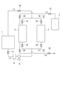
- a processing system for treating a development waste solution containing a polymer component generated in this development step for example, FIG. The thing of the structure shown in 1 is mentioned.
- the processing system includes a first pipe L1 connected to an outlet of the developing machine 1 that discharges development waste liquid, a first packed bed 2 and a second packed bed 3 connected to the first pipe L1, 2nd piping L2 connected to each 1st outflow port of the 1st packed bed 2 and the 2nd packed bed 3, the washing
- the developing waste liquid is discharged from the outlet of the developing machine 1, and the first pipe L1 connected thereto serves as a waste liquid collecting unit for collecting the developing waste liquid.
- a waste liquid recovery tank for storing developer waste liquid may be provided in the first pipe L1 path, and this recovery tank may be used as a waste liquid recovery unit.
- the first packed bed 2 and the second packed bed 3 are each filled with activated carbon.
- the developing waste liquid is passed through either the first packed bed 2 or the second packed bed 3 from the first pipe L1.
- the passing liquid that has passed through one of the packed beds is returned from the first outlet to the aqueous developer supply unit in the developing machine 1 through the second pipe L2, and the second pipe L2 passes through the passing liquid return unit. It becomes.
- recovery tank which stores a passage liquid in this 2nd piping L2 path
- the first pipe L1 is arranged between the developing machine 1, the first packed bed 2 and the second packed bed 3.
- a liquid feed pump 5 is installed in the middle of the first pipe L1 so that the developing waste liquid can be sent from the developing machine 1 to the first packed bed 2 or the second packed bed 3.
- the first pipe L1 is bifurcated in the middle, and one of the branched ends is connected to the first packed bed 2 and the other is connected to the second packed bed 3.
- a valve 11 is provided between the branch point and the developing machine 1, and valves 12 and 13 are provided between the branch point and the first packed bed 2 or the second packed bed 3, respectively.
- the connection / disconnection state of the first pipe L1 with the first packed bed 2 is switched by opening / closing the valve 12, and the connection / disconnection state with the second packed bed 3 is switched by opening / closing the valve 13. Can be switched.
- the second pipe L2 is arranged between the developing machine 1, the first packed bed 2 and the second packed bed 3.
- the second pipe L ⁇ b> 2 is bifurcated in the middle, and one of the branched groups is connected to the first packed bed 2 and the other is connected to the second packed bed 3.
- a valve 16 is provided between the branch point and the developing machine 1, and valves 14 and 15 are provided between the branch point and the first packed bed 2 or the second packed bed 3, respectively.
- the connection / disconnection state of the second pipe L2 with the first packed bed 2 is switched by opening / closing the valve 14, and the connection / disconnection state with the second packed bed 3 is switched by opening / closing the valve 15. Can be switched.
- the developing waste liquid is sent from the developing machine 1 to the first packed bed 2 or the second packed bed 3 through the first pipe L1.
- the developing waste liquid is passed through the first packed bed 2 by opening the valves 11 and 12 and closing the valve 13.
- the valves 16, 14 are opened and the valve 15 is closed, so that the liquid passing through the first packed bed 2 passes through the second pipe L 2 and the developing machine. 1 is returned to the aqueous developer supply section and reused as an aqueous developer.
- the developing waste liquid is passed through the second packed bed 3 by opening the valves 11 and 13 and closing the valve 12.
- the valves 16 and 15 are opened and the valve 14 is closed, so that the liquid passing through the second packed bed 3 passes through the second pipe L2 and the developing machine. 1 is returned to the aqueous developer supply section and reused as an aqueous developer.
- the cleaning unit 4 is connected to the first packed bed 2 and the second packed bed 3 through a third pipe L3, and includes a boiler, a heater, and the like that send water vapor to these packed beds.
- the third pipe L3 is disposed between the cleaning unit 4 and the first packed bed 2 and the second packed bed 3.
- the third pipe L3 is bifurcated in the middle, and one of the branched ends is connected to the first packed bed 2 and the other is connected to the second packed bed 3.
- a valve 17 is provided between the branch point and the cleaning unit 4, and valves 18 and 19 are provided between the branch point and the first packed bed 2 or the second packed bed 3, respectively.
- connection / disconnection state of the third pipe L3 with the first packed bed 2 is switched by the opening / closing operation of the valve 18, and the connection / disconnection state with the second filling bed 3 is switched by the opening / closing operation of the valve 19. Can be switched.
- the fourth pipe L4 is connected to each second outlet of the first packed bed 2 and the second packed bed 3.
- the fourth pipe L4 is bifurcated in the middle, and one of the branched groups is connected to the first packed bed 2 and the other is connected to the second packed bed 3.
- a valve 22 is provided between the branch point and the discharge port, and valves 20 and 21 are provided between the branch point and the first packed bed 2 or the second packed bed 3, respectively.
- the fourth pipe L4 is switched between connected and disconnected with the first packed bed 2 by opening and closing the valve 20, and connected and disconnected with the second packed bed 3 by opening and closing the valve 21. Can be switched.
- the water vapor from the cleaning unit 4 is sent to the first packed bed 2 or the second packed bed 3 through the third pipe L3.
- the water vapor is passed through the first packed bed 2 by opening the valves 17 and 18 and closing the valve 19.
- the valves 20, 22 are opened and the valve 21 is closed in conjunction with the opening / closing operation of the valves 17, 18, 19, the water vapor that has passed through the first packed bed 2 passes through the fourth pipe L4. It is discharged from the outlet. Thereby, the cleaning process of the first packed bed 2 is performed.
- the first packed bed 2 and the second packed bed 3 are each formed by a waste liquid process for passing the developing waste liquid through the packed bed and a cleaning process for cleaning the activated carbon in the packed bed through the developed waste liquid by opening and closing the valves 11 to 22. It is possible to switch alternately.
- waste liquid treatment is performed in the first packed bed 2, and the passing liquid is used as the aqueous developer of the developing machine 1. It is returned to the supply unit and reused as an aqueous developer.
- the valves 17, 19, 21, and 22 are opened, and the valves 18 and 20 are closed, so that the activated carbon in the second packed bed 3 is washed by passing water vapor through the second packed bed 3. Perform the cleaning process.
- valves 19 and 21 are closed, and between the cleaning unit 4 (third pipe L3) and the second packed bed 3 and between the second packed bed 3 and the fourth pipe L4 (discharge port).
- the valves 12 and 14 are closed, and between the developing machine 1 (first pipe L1) and the first packed bed 2 and between the first packed bed 2 and the second pipe L2.
- the valves 13 and 15 are opened, and between the developing machine 1 (first pipe L1) and the second packed bed 3 and between the second packed bed 3 and the second pipe L2.
- the waste liquid treatment is switched from the first packed bed 2 to the second packed bed 3 by connecting the outlet to the outlet.
- the first packed bed 2 is switched to a cleaning process and is prepared for a waste liquid process to be performed next time.
- the cleaning process and the waste liquid process can be alternately performed by opening and closing the valve.
- the activated carbon of the packed bed can be regenerated and the packed bed can be used again for waste liquid treatment without replacing the activated carbon.
- the waste liquid treatment can be continuously performed by using two packed beds and sequentially switching the packed bed for performing the waste liquid treatment by opening and closing the valve as described above.
- the example using two packed beds was shown in the said embodiment, even if it uses three or more packed beds, the packed bed which performs waste liquid processing by the same operation is switched sequentially, and waste liquid processing is performed continuously. be able to.
- the opening / closing operation of the valve may be performed manually or by automatic control by a control unit (not shown).
- the developer waste liquid is passed through the packed bed filled with activated carbon, not only the aggregates in the developer waste liquid are removed, but also the polymer dissolved in the developer waste liquid. Components and additives can also be removed from the developer waste by adsorption. Accordingly, the passing liquid can be returned to the aqueous developer supply section of the developing machine and reused as the aqueous developer, so that a processing system that does not discard the developing waste liquid can be obtained.
- the water-insoluble polymer dispersed in the developing waste liquid can be aggregated using a polymer flocculant.
- the agglomerated polymer component can be removed as a solid content using a filter such as a nonwoven fabric. For example, as shown in FIG. 2, by installing a filter 6 on the upstream side of the packed bed and removing the solid content from the development waste liquid in advance, the components removed in the packed bed can be reduced. Then, since the amount of the component adsorbed on the activated carbon of the packed bed is reduced, the frequency of regenerating the activated carbon can be reduced.
- ⁇ Preparation of photosensitive resin composition > 54.6 parts by weight of water-dispersed latex (30 parts by weight of polymer as solid content), 10 parts by weight of acrylic-modified liquid BR, and 10 parts by weight of acrylic monomer are mixed and heated in a dryer heated to 120 ° C. for 2 hours. Water was evaporated to obtain a mixture of a polymer obtained from the water-dispersed latex and a photopolymerizable monomer.
- This mixture 25 parts by mass of BR, 8 parts by mass of a surfactant (4 parts by mass of a polymer as a solid content), and 10 parts by mass of a plasticizer were kneaded in a kneader for 45 minutes. Thereafter, 0.2 parts by mass of a thermal polymerization inhibitor and 1 part by mass of a photopolymerization initiator were put into a kneader and kneaded for 5 minutes to obtain a photosensitive resin composition.
- a polymer obtained from water-dispersed latex (Nipol LX111NF, manufactured by Zeon Corporation).
- -BR [Nippon BR1220, manufactured by Nippon Zeon Co., Ltd.]
- -Acrylic modified liquid BR [Osaka Organic Chemical Co., Ltd., BAC-45] ⁇
- Acrylic monomer [1,9-nonanediol dimethacrylate, manufactured by NOF Corporation]
- -Photopolymerization initiator [Ciba Japan Co., Ltd., Irgacure 651]
- -Surfactant [manufactured by NOF Corporation, Newlex R]
- Plasticizer [Esso Oil Co., Ltd., Christol 70]
- Thermal polymerization inhibitor [Seiko Chemical Co., Ltd., MEHQ (hydroquinone monomethyl ether)]
- the photosensitive resin composition thus obtained was coated with an adhesive on one side of a 125 ⁇ m-thick PET film, and a protective film with an anti-blocking agent applied on one side of a 100 ⁇ m-thick PET film. And the adhesive layer, the photosensitive layer made of the photosensitive resin composition, on the substrate by pressing with a press machine heated to 120 ° C. so that the thickness of the photosensitive resin composition is 1 mm, A printing plate material in which an anti-sticking agent layer and a protective film were laminated in this order was produced.
- the base is formed by irradiating ultraviolet rays from the substrate side of the printing plate material, and then the protective film is peeled off, and a negative film for image reproducibility evaluation (on the photosensitive layer)
- the halftone dots “150 Lpi / 2%” and “independent point ⁇ 120 ⁇ m” were brought into close contact with each other in vacuum, and the negative film was exposed for 6 minutes from the distance of 15 cm (main exposure) with the above exposure apparatus. Thereafter, the negative film was removed, washed out with an aqueous developer containing a surfactant (1% by mass) for 10 minutes, and then sufficiently dried with hot air at 50 ° C.
- the printing plate was produced by the above.
Landscapes
- Chemical & Material Sciences (AREA)
- Analytical Chemistry (AREA)
- Chemical Kinetics & Catalysis (AREA)
- Engineering & Computer Science (AREA)
- Environmental & Geological Engineering (AREA)
- Physics & Mathematics (AREA)
- General Physics & Mathematics (AREA)
- Life Sciences & Earth Sciences (AREA)
- Sustainable Development (AREA)
- Photosensitive Polymer And Photoresist Processing (AREA)
Abstract
現像廃液中に溶解する成分も除去することにより現像廃液の再利用を可能にする印刷版現像液の処理方法および印刷版現像液の処理システムを提供する。 潜像形成された感光性樹脂層を有する印刷版材に水を主成分とする水系現像液を用いて現像を行う現像工程で発生するポリマー成分を含む現像廃液を、活性炭が充填された充填層2,3に通し、その通過液を現像機1の水系現像液の供給部に戻して水系現像液として再使用する、印刷版現像液の処理方法。
Description
本発明は、印刷版現像液の処理方法および印刷版現像液の処理システムに関し、さらに詳しくは、水系現像液を用いて現像を行う現像工程で発生するポリマー成分を含む現像廃液について行う印刷版現像液の処理方法および印刷版現像液の処理システムに関するものである。
従来より、印刷版を用いて、包装材やラベル、雑誌等の被刷体に、凸版印刷、凹版印刷、あるいは、平版印刷が行われている。印刷版の原版は、PET樹脂などの基板上に感光性樹脂組成物よりなる感光層を備えている。印刷版は、この感光層に密着させたネガフィルムを介して感光層に紫外線を照射し、未硬化部分を除去することでレリーフ像を形成したものである。
印刷版の現像方法としては各種方法が知られているが、例えば水を主成分とする水系現像液を用いて現像を行う現像方法では、水系現像液中に印刷版を浸漬し、ブラシで水系現像液中に未硬化部分をこすり出すことにより現像が行われている。現像廃液にはこすり出されたポリマー成分が含まれ、現像液としてそのまま再利用すると新たな印刷版を汚すため、現像廃液は廃棄されることがあった。しかし、これでは大量の廃棄物を発生させるため、環境面から改善が求められていた。
そこで、例えば特許文献1では、フィルターを用いて現像廃液中の凝集物を除去し、その濾液を現像液として再利用する方法が提案されている。また、例えば特許文献2では、現像廃液に凝集剤を添加して凝集させたポリマー成分を現像廃液から除去する方法が提案されている。
しかしながら、水系現像液を用いて現像を行う現像方法において、現像廃液に含まれるポリマー成分はすべて凝集しているわけではなく、現像廃液中に溶解しているものも存在する。また、感光層の未硬化部分にはポリマー成分の他に添加剤も含まれることがあり、現像廃液中に溶解する添加剤も存在する。フィルターを用いて現像廃液中の凝集物を除去するだけではこれらの溶解物までを現像廃液から除去することはできず、現像廃液の再利用を難しくする。
また、凝集剤を用いると現像廃液中に凝集剤が残るおそれがあり、これを現像液として再利用すると現像時にこすり出されたポリマー成分が凝集して印刷版やブラシなどに付着するおそれがある。また、現像廃液中に溶解する水溶性ポリマーは凝集剤を用いて凝集させることが難しい。
本発明は、上記事情に鑑みてなされたものであり、本発明が解決しようとする課題は、現像廃液中に溶解する成分も除去することにより現像廃液の再利用を可能にする印刷版現像液の処理方法および印刷版現像液の処理システムを提供することにある。
上記課題を解決するため、本発明に係る印刷版現像液の処理方法は、潜像形成された感光性樹脂層を有する印刷版材に水を主成分とする水系現像液を用いて現像を行う現像工程で発生するポリマー成分を含む現像廃液を、活性炭が充填された充填層に通し、その通過液を現像機の水系現像液の供給部に戻して水系現像液として再使用することを要旨とするものである。
この際、現像廃液を通した充填層に水蒸気を通して充填層の活性炭を洗浄する洗浄処理を、活性炭が充填された充填層に現像廃液を通す廃液処理と切り替えて交互に行うことが好ましい。
そして、複数の充填層を用い、廃液処理を行う充填層を順次切り替えて連続して廃液処理を行うとともに、廃液処理を停止した充填層に対し他の充填層が廃液処理を行うときに洗浄処理を行うことが好ましい。
また、本発明に係る印刷版現像液の処理システムは、潜像形成された感光性樹脂層を有する印刷版材に水を主成分とする水系現像液を用いて現像を行う現像工程で発生するポリマー成分を含む現像廃液を回収する廃液回収部と、該廃液回収部に接続され、現像廃液を通すための、活性炭が充填された充填層と、該充填層に接続され、充填層を通過した通過液を現像機における水系現像液の供給部に戻す通過液戻し部と、を備えることを要旨とするものである。
この際、前記充填層に接続され、現像廃液を通した充填層に水蒸気を通して充填層の活性炭を洗浄する洗浄部、をさらに備え、前記充填層に現像廃液を通す廃液処理と現像廃液を通した充填層の活性炭を洗浄する洗浄処理とを切り替えて交互に行うことを可能にすることが好ましい。
そして、複数の充填層を備え、廃液処理を行う充填層を切り替え可能に各充填層が共通の廃液回収部に接続されるとともに、洗浄処理を行う充填層を切り替え可能に各充填層が共通の洗浄部に接続され、廃液処理を行う充填層を順次切り替えて連続して廃液処理を行うとともに廃液処理を停止した充填層に対し他の充填層が廃液処理を行うときに洗浄処理を行うことを可能にすることが好ましい。
本発明に係る印刷版現像液の処理方法によれば、水を主成分とする水系現像液を用いて現像を行う現像工程で発生するポリマー成分を含む現像廃液を活性炭が充填された充填層に通すので、現像廃液中の凝集物を除去するだけでなく、現像廃液中に溶解するポリマー成分や添加剤なども吸着によって現像廃液から除去することができる。これにより、その通過液を現像機の水系現像液の供給部に戻して水系現像液として再使用することができるため、現像廃液を廃棄しない処理システムにすることができる。
この際、現像廃液を通した充填層に水蒸気を通して充填層の活性炭を洗浄する洗浄処理を、活性炭が充填された充填層に現像廃液を通す廃液処理と切り替えて交互に行うことにより、充填層の活性炭を再生して、活性炭の交換を行うことなく充填層を再び廃液処理に用いることができる。
そして、複数の充填層を用い、廃液処理を行う充填層を順次切り替えて廃液処理を行うとともに、廃液処理を停止した充填層に対し他の充填層が廃液処理を行うときに洗浄処理を行うことにより、廃液処理を連続して行うことができる。
また、本発明に係る印刷版現像液の処理システムによれば、ポリマー成分を含む現像廃液を廃液回収部から充填層に通して現像廃液中の凝集物と溶解成分を現像廃液から除去し、その通過液を通過液戻し部から現像機の水系現像液の供給部に戻して水系現像液として再使用することができるため、現像廃液を廃棄しない処理システムにすることができる。
この際、前記充填層に接続され、現像廃液を通した充填層に水蒸気を通して充填層の活性炭を洗浄する洗浄部、をさらに備え、前記充填層に現像廃液を通す廃液処理と現像廃液を通した充填層の活性炭を洗浄する洗浄処理とを切り替えて交互に行うことにより、充填層の活性炭を再生して、活性炭の交換を行うことなく充填層を再び廃液処理に用いることができる。
そして、複数の充填層を備え、廃液処理を行う充填層を切り替え可能に各充填層が共通の廃液回収部に接続されるとともに、洗浄処理を行う充填層を切り替え可能に各充填層が共通の洗浄部に接続され、廃液処理を行う充填層を順次切り替えて連続して廃液処理を行うとともに廃液処理を停止した充填層に対し他の充填層が廃液処理を行うときに洗浄処理を行うことにより、廃液処理を連続して行うことができる。
次に、本発明の実施形態について説明する。
本発明において用いられる印刷版材は、水を主成分とする水系現像液を用いて現像を行う印刷版材である。印刷版材は、感光層を有するものからなる。感光層は、例えば基板上に形成される。基板としては、例えばPETフィルムなどのプラスチックフィルム(プラスチックシート)、ステンレス、アルミニウムなどの金属シート、ブタジエンゴムなどのゴムシートなどが挙げられる。
感光層は、感光性樹脂組成物を層状に成形したものである。感光性樹脂組成物は、樹脂、ゴム、ラテックスなどのポリマー成分、光重合性モノマー、光重合開始剤を含み、必要に応じて添加剤などをさらに含むものから構成される。ポリマー成分は、水溶性(あるいは親水性)であってもよいし、非水溶性(あるいは疎水性)であってもよい。
ポリマー成分の樹脂としては、ポリアミド、ポリビニルアルコール、ポリエステル、ポリウレタンなどが挙げられる。ゴムとしては、ブタジエンゴム、クロロプレンゴム、アクリロニトリルブタジエンゴムなどが挙げられる。
水系現像液を用いて現像を行う場合、感光性樹脂組成物の現像液で洗い出される成分としては、水溶性(あるいは親水性)成分や非水溶性(あるいは疎水性)成分がある。水溶性成分に含まれる水溶性ポリマー(あるいは親水性ポリマー)としては、ポリアミドに親水性成分を導入した水溶性または水膨潤性ポリアミド(25℃/24時間の水浸漬で、水に完全溶解又は完全分散するポリアミド)や、部分ケン化ポリ酢酸ビニルやその誘導体などが挙げられる。非水溶性成分に含まれる非水溶性ポリマー(あるいは疎水性ポリマー)としては、各種ミラブルゴムが挙げられる。具体的には、ブタジエンゴム、クロロプレンゴム、アクリロニトリルブタジエンゴム、アクリルゴム、エピクロルヒドリンゴム、ウレタンゴム、イソプレンゴム、スチレンイソプレンゴム、スチレンブタジエンゴム、エチレン-プロピレン共重合体、塩素化ポリエチレンなどが挙げられる。
非水溶性ポリマーを含む感光性樹脂組成物では、ポリマー成分の少なくとも一部が溶解しないで分散するので、洗い出し液の粘性が低く、廃液処理を行いやすい利点がある。
印刷版材のうちフレキソ印刷版材の感光性樹脂組成物としては、例えば、水分散ラテックス、ミラブルゴム、光重合性モノマー、光重合開始剤、を含有するものを挙げることができる。
水分散ラテックスとは、重合体粒子を分散質として水中に分散したものである。この水分散ラテックスから水を除去することにより、重合体が得られる。水分散ラテックスは、感光性樹脂組成物に水現像性を付与することができる。
水分散ラテックスとしては、具体的には、ポリブタジエンラテックス、天然ゴムラテックス、スチレン-ブタジエン共重合体ラテックス、アクリロニトリル-ブタジエン共重合体ラテックス、ポリクロロプレンラテックス、ポリイソプレンラテックス、ポリウレタンラテックス、メチルメタクリレート-ブタジエン共重合体ラテックス、ビニルピリジン重合体ラテックス、ブチル重合体ラテックス、チオコール重合体ラテックス、アクリレート重合体ラテックスなどの水分散ラテックス重合体やこれら重合体にアクリル酸やメタクリル酸などの他の成分を共重合して得られる重合体などを挙げることができる。これらは単独で用いても良いし、2種以上を併合して用いても良い。
このうち、硬度の点などから、分子鎖中にブタジエン骨格またはイソプレン骨格を含有する水分散ラテックス重合体が好ましい。具体的には、ポリブタジエンラテックス、スチレン-ブタジエン共重合体ラテックス、アクリロニトリル-ブタジエン共重合体ラテックス、メチルメタクリレート-ブタジエン共重合体ラテックス、アクリル酸-メチルメタクリレート-ブタジエン共重合体ラテックス、ポリイソプレンラテックスが好ましい。
ミラブルゴムは、感光性樹脂組成物のゴム弾性を増加させることができる。これにより、例えば、種々の被刷体に印刷しやすくできるなどの効果が期待できる。ミラブルゴムとしては、具体的には、ブタジエンゴム(BR)、ニトリルゴム(NBR)、アクリルゴム、エピクロルヒドリンゴム、ウレタンゴム、イソプレンゴム、スチレンイソプレンゴム、スチレンブタジエンゴム、エチレン-プロピレン共重合体、塩素化ポリエチレンなどを挙げることができる。これらは単独で用いても良いし、2種以上を併合して用いても良い。
このうち、感光性樹脂組成物の水現像性、乾燥性、画像再現性を向上できるなどの観点から、ブタジエンゴム(BR)、ニトリルゴム(NBR)が好ましい。さらには、感光性樹脂組成物中でゴム成分が特に微分散しやすく、これにより、微細形状の再現性に優れ、より一層、画像再現性を向上できるなどの観点から、ブタジエンゴム(BR)が好ましい。
光重合性モノマーは、感光性樹脂組成物を硬化させ、あるいは、架橋させることができる。光重合性モノマーとしては、エチレン性不飽和化合物を挙げることができる。エチレン性不飽和化合物としては、(メタ)アクリルモノマー、(メタ)アクリルオリゴマー、(メタ)アクリル変性重合体などを挙げることができる。(メタ)アクリル変性重合体としては、例えば(メタ)アクリル変性ブタジエンゴム、(メタ)アクリル変性ニトリルゴムなどを挙げることができる。
エチレン性不飽和化合物は、エチレン性不飽和結合を1個だけ有する化合物であっても良いし、エチレン性不飽和結合を2つ以上有する化合物であっても良い。
エチレン性不飽和結合を1個だけ有するエチレン性不飽和化合物としては、具体的には、2-ヒドロキシエチル(メタ)アクリレート・2-ヒドロキシプロピル(メタ)アクリレート・2-ヒドロキシブチル(メタ)アクリレート・3-クロロ-2-ヒドロキシプロピル(メタ)アクリレート・β-ヒドロキシ-β’-(メタ)アクリロイルオキシエチルフタレート等の水酸基を有する(メタ)アクリレート、メチル(メタ)アクリレート・エチル(メタ)アクリレート・プロピル(メタ)アクリレート・ブチル(メタ)アクリレート・イソアミル(メタ)アクリレート・2-エチルヘキシル(メタ)アクリレート・ラウリル(メタ)アクリレート・ステアリル(メタ)アクリレート等のアルキル(メタ)アクリレート、シクロヘキシル(メタ)アクリレート等のシクロアルキル(メタ)アクリレート、クロロエチル(メタ)アクリレート・クロロプロピル(メタ)アクリレート等のハロゲン化アルキル(メタ)アクリレート、メトキシエチル(メタ)アクリレート・エトキシエチル(メタ)アクリレート・ブトキシエチル(メタ)アクリレート等のアルコキシアルキル(メタ)アクリレート、フェノキシエチルアクリレート・ノニルフェノキシエチル(メタ)アクリレート等のフェノキシアルキル(メタ)アクリレート、エトキシジエチレングリコール(メタ)アクリレート・メトキシトリエチレングリコール(メタ)アクリレート・メトキシジプロピレングレコール(メタ)アクリレート等のアルコキシアルキレングリコール(メタ)アクリレート、2、2-ジメチルアミノエチル(メタ)アクリレート・2,2-ジエチルアミノエチル(メタ)アクリレート・2-ヒドロキシエチル(メタ)アクリレート・3-クロロ-2-ヒドロキシプロピル(メタ)アクリレート等を挙げることができる。
エチレン性不飽和結合を2つ以上有するエチレン性不飽和化合物としては、具体的には、1,9-ノナンジオールジ(メタ)アクリレートなどのアルキルジオールジ(メタ)アクリレート、ジエチレングリコールジ(メタ)アクリレートなどのポリエチレングリコールジ(メタ)アクリレート、ジプロピレングリコールジ(メタ)アクリレートなどのポリプロピレングリコールジ(メタ)アクリレート、トリメチロールプロパントリ(メタ)アクリレート、ペンタエリスリトールトリ(メタ)アクリレート、ペンタエリスリトールテトラ(メタ)アクリレート、グリセロールトリ(メタ)アクリレート、エチレングリコールジグリシジルエーテルに不飽和カルボン酸や不飽和アルコール等のエチレン性不飽和結合と活性水素を持つ化合物を付加反応させて得られる多価(メタ)アクリレート、グリシジル(メタ)アクリレート等の不飽和エポキシ化合物とカルボン酸やアミンのような活性水素を有する化合物を付加反応させて得られる多価(メタ)アクリレート、メチレンビス(メタ)アクリルアミド等の多価(メタ)アクリルアミド、ジビニルベンゼン等の多価ビニル化合物等を挙げることができる。
光重合開始剤は、光重合性モノマーの光重合を開始させるものであれば特に限定されず、例えば、アルキルフェノン類、アセトフェノン類、ベンゾインエーテル類、ベンゾフェノン類、チオキサントン類、アントラキノン類、ベンジル類、ビアセチル類等の光重合開始剤を挙げることができる。具体的には、例えば、ベンジルジメチルケタール、2-ヒドロキシ-2-メチル-1-フェニル-プロパン-1-オン、メチル-O-ベンゾイルベンゾエート、1-ヒドロキシシクロヘキシルフェニルケトンなどを挙げることができる。
感光性樹脂組成物における水分散ラテックスとミラブルゴムの配合比率は、水分散ラテックスとミラブルゴムの合計質量に対する水分散ラテックスの質量の比率で20~90%の範囲内であることが好ましい。より好ましくは30~80%の範囲内、さらに好ましくは50~70%の範囲内である。この質量比率が20%以上であると、高速で水現像を行うことができる。これは、感光性樹脂組成物への水系現像液の浸透性が高くなるためと推察される。一方、この質量比率が90%以下であると、画像再現性に優れる。
感光性樹脂組成物における光重合性モノマーの含有量は、好ましくは10~80質量%の範囲内、より好ましくは20~50質量%の範囲内である。光重合性モノマーの含有量が10質量%以上であれば、架橋密度の不足がなく、良好な画像再現性とインク耐性が得られる。一方、光重合性モノマーの含有量が80質量%以下であれば、レリーフが脆くなく、かつ、フレキソ印刷版の特徴である柔軟性を確保することができる。
感光性樹脂組成物における光重合開始剤の含有量は、好ましくは0.3~10質量%の範囲内、より好ましくは0.5~5質量%の範囲内である。光重合開始剤の含有量が0.3質量%以上であれば、光重合性モノマーの光重合反応が十分に起こり、良好な画像が形成できる。一方、光重合性モノマーの含有量が5質量%以下であれば、感度が高すぎないため、露光時間の調節が容易になる。
感光性樹脂組成物においては、水現像性を向上するなどの目的で、界面活性剤を含有することができる。界面活性剤としては、カチオン性界面活性剤、アニオン性界面活性剤、ノニオン性界面活性剤を挙げることができる。界面活性剤のうち、アニオン性界面活性剤が特に好ましい。
アニオン性界面活性剤としては、具体的には、ラウリン酸ナトリウム・オレイン酸ナトリウム等の脂肪族カルボン酸塩、ラウリル硫酸エステルナトリウム・セチル硫酸エステルナトリウム・オレイル硫酸エステルナトリウム等の高級アルコール硫酸エステル塩、ポリオキシエチレンラウリルエーテル硫酸エステルナトリウム等のポリオキシエチレンアルキルエーテル硫酸エステル塩、ポリオキシエチレンオクチルフェニルエーテル硫酸エステルナトリウム・ポリオキシエチレンノニルフェニルエーテル硫酸エステルナトリウム等のポリオキシエチレンアルキルアリルエーテル硫酸エステル塩、アルキルジフェニルエーテルジスルホン酸塩・ドデシルスルホン酸ナトリウム、ジアルキルスルホコハク酸ナトリウム等のアルキルスルホン酸塩、アルキルジスルホン酸塩・ドデシルベンゼンスルホン酸ナトリウム・ジブチルナフタレンスルホン酸ナトリウム・トリイソプロピルナフタレンスルホン酸ナトリウム等のアルキルアリルスルホン酸塩、ラウリルリン酸モノエステルジナトリウム・ラウリルリン酸ジエステルナトリウム等の高級アルコールリン酸エステル塩、ポリオキシエチレンラウリルエーテルリン酸モノエステルジナトリウム・ポリオキシエチレンラウリルエーテルリン酸ジエステルナトリウム等のポリオキシエチレンアルキルエーテルリン酸エステル塩等を挙げることができる。これらは単独で用いても良いし、2種以上を併合して用いても良い。なお、具体例としてナトリウム塩を挙げたが、特にナトリウム塩に限定されるものではなく、カルシウム塩、アンモニア塩などでも同様の効果を得ることができる。
このうち、より一層、感光性樹脂組成物の水現像性に優れるなどの観点から、アルキルスルホン酸塩、アルキルアリルスルホン酸塩などのスルホン酸系界面活性剤が好ましい。
感光性樹脂組成物における界面活性剤の含有量は、水分散ラテックスとミラブルゴムと界面活性剤の合計質量に対する界面活性剤の質量の比率として、0.1~20%の範囲内であることが好ましい。より好ましくは0.1~15%の範囲内、さらに好ましくは0.1~10%の範囲内である。この質量比率を0.1%以上にすることにより、短時間で水現像を行うことができる。これは、感光性樹脂組成物への水系現像液の浸透性が高くなるためと推察される。また、この質量比率を20%以下にすることにより、乾燥性が良くなる。
感光性樹脂組成物においては、柔軟性を付与するなどの目的で、可塑剤を含有することができる。また、可塑剤を含有することにより、感光性樹脂組成物の硬さを抑えることができるため、光重合性モノマーの含有量を増やすことができる。これにより、インク耐性を向上できる。
可塑剤としては、液状ゴム、オイル、ポリエステル、リン酸系化合物などを挙げることができる。特に、水分散ラテックスあるいはミラブルゴムと相溶性が良好なものが好ましい。液状ゴムとしては、例えば液状のポリブタジエン、液状のポリイソプレン、あるいは、これらをマレイン酸やエポキシ基により変性したものなどを挙げることができる。オイルとしては、パラフィン、ナフテン、アロマなどを挙げることができる。ポリエステルとしては、アジピン酸系ポリエステルなどを挙げることができる。リン酸系化合物としては、リン酸エステルなどを挙げることができる。
感光性樹脂組成物における可塑剤の含有量は、0.1~30質量%の範囲内であることが好ましい。より好ましくは5~20質量%の範囲内である。可塑剤の含有量が0.1質量%以上であれば、感光性樹脂組成物に柔軟性を付与できるため、溶剤インクによる感光性樹脂組成物の膨潤が抑えられる。すなわち、溶剤インクに対する耐性(耐溶剤インク膨潤性)が向上する。一方、可塑剤の含有量が30質量%以下であれば、感光性樹脂組成物の強度を確保できる。
感光性樹脂組成物においては、混練時の熱安定性を高める、貯蔵安定性を高めるなどの観点から、熱重合禁止剤(安定剤)を添加することができる。熱重合禁止剤としては、フェノール類、ハイドロキノン類、カテコール類のものなどを挙げることができる。感光性樹脂組成物における熱重合禁止剤の含有量は、0.001~5質量%の範囲内が一般的である。
感光性樹脂組成物においては、本発明の効果を阻害しない範囲において、種々の特性向上を目的として、さらに紫外線吸収剤、染料、顔料、消泡剤、香料などの他の成分を適宜添加することができる。
本発明に係る感光性樹脂組成物は、例えば、各成分などを混練しながら脱水することにより調製できる。あるいは、水分散ラテックスを予め脱水した後、水分散ラテックスから得られた重合体と、他の成分などとを混練することにより調製できる。混練時に用いる混練機としては、2軸押出機、単軸押出機、ニーダー、バンバリーミキサーなどを挙げることができる。
水系現像液としては、水のみからなる液であってもよく、また、水を主成分とし水に可溶な化合物を添加した水溶液であってもよい。水に可溶な化合物としては、界面活性剤、酸、アルカリ、塩などが挙げられる。界面活性剤としては、上記するものなどが挙げられる。
また、水系現像液としては、水に可溶な有機溶媒を含んでいてもよい。このような有機溶媒としては、メタノール、エタノール、イソプロピルアルコール、セロソルブ、グリセリン、ポリエチレングリコール、ジメチルホルムアミド、ジメチルアセトアミド、アセトンなどが挙げられる。
酸としては、硫酸、硝酸、リン酸、ギ酸、酢酸、シュウ酸、コハク酸、クエン酸、マレイン酸、パラトルエンスルホン酸などの無機酸や有機酸が挙げられる。アルカリとしては、水酸化リチウム、水酸化ナトリウム、水酸化カリウム、水酸化カルシウムなどが挙げられる。
上記水系現像液を用いて、潜像形成された感光性樹脂層を有する印刷版材に現像を行うが、この現像工程で発生するポリマー成分を含む現像廃液を処理する処理システムとしては、例えば図1に示す構成のものが挙げられる。
処理システムは、現像廃液を排出する現像機1の流出口に接続された第一の配管L1と、第一の配管L1に接続された第一の充填層2および第二の充填層3と、第一の充填層2および第二の充填層3の各第一の流出口に接続された第二の配管L2と、洗浄部4と、洗浄部4と第一の充填層2の間および洗浄部4と第二の充填層3の間に配された第三の配管L3と、第一の充填層2および第二の充填層3の各第二の流出口に接続された第四の配管L4と、を備えている。
現像廃液は現像機1の流出口から排出され、これに接続される第一の配管L1が現像廃液を回収する廃液回収部となる。なお、この第一の配管L1経路内に現像廃液を溜めておく廃液回収タンクを設け、この回収タンクを廃液回収部としてもよい。第一の充填層2および第二の充填層3には、それぞれ活性炭が充填されている。現像廃液は第一の配管L1から第一の充填層2および第二の充填層3のいずれか一方に通される。いずれか一方の充填層を通過した通過液は第一の流出口から第二の配管L2を通って現像機1における水系現像液の供給部に戻され、第二の配管L2が通過液戻し部となる。なお、この第二の配管L2経路内に通過液を溜めておく通過液回収タンクを設け、この通過液回収タンクを通過液戻し部としてもよい。
第一の配管L1は、現像機1と第一の充填層2および第二の充填層3との間に配されている。第一の配管L1の途中には送液ポンプ5が設置されており、現像機1から第一の充填層2あるいは第二の充填層3に現像廃液を送ることができるようになっている。第一の配管L1は途中で二又に分岐しており、その分岐した先の一方が第一の充填層2に接続され、他方が第二の充填層3に接続されている。その分岐点と現像機1の間にはバルブ11が設けられ、分岐点と第一の充填層2あるいは第二の充填層3の間にはそれぞれバルブ12,13が設けられている。第一の配管L1は、バルブ12の開閉操作により第一の充填層2との接続/非接続状態が切り替えられ、バルブ13の開閉操作により第二の充填層3との接続/非接続状態が切り替えられる。
第二の配管L2は、現像機1と第一の充填層2および第二の充填層3との間に配されている。第二の配管L2は途中で二又に分岐しており、その分岐した基の一方が第一の充填層2に接続され、他方が第二の充填層3に接続されている。その分岐点と現像機1の間にはバルブ16が設けられ、分岐点と第一の充填層2あるいは第二の充填層3の間にはそれぞれバルブ14,15が設けられている。第二の配管L2は、バルブ14の開閉操作により第一の充填層2との接続/非接続状態が切り替えられ、バルブ15の開閉操作により第二の充填層3との接続/非接続状態が切り替えられる。
したがって、現像廃液は、現像機1から第一の配管L1を通って第一の充填層2あるいは第二の充填層3に送られる。このとき、バルブ11,12を開にし、バルブ13を閉にすることにより、現像廃液は第一の充填層2に通される。バルブ11,12,13の開閉操作と連動してバルブ16,14を開にし、バルブ15を閉にすることにより、第一の充填層2の通過液は第二の配管L2を通って現像機1の水系現像液の供給部に戻され、水系現像液として再使用される。
また、このとき、バルブ11,13を開にし、バルブ12を閉にすることにより、現像廃液は第二の充填層3に通される。バルブ11,12,13の開閉操作と連動してバルブ16,15を開にし、バルブ14を閉にすることにより、第二の充填層3の通過液は第二の配管L2を通って現像機1の水系現像液の供給部に戻され、水系現像液として再使用される。
洗浄部4は、第三の配管L3を介して第一の充填層2および第二の充填層3に接続されており、これらの充填層に水蒸気を送るボイラ、ヒータなどの装置からなる。第三の配管L3は、洗浄部4と第一の充填層2および第二の充填層3との間に配されている。第三の配管L3は途中で二又に分岐しており、その分岐した先の一方が第一の充填層2に接続され、他方が第二の充填層3に接続されている。その分岐点と洗浄部4の間にはバルブ17が設けられ、分岐点と第一の充填層2あるいは第二の充填層3の間にはそれぞれバルブ18,19が設けられている。第三の配管L3は、バルブ18の開閉操作により第一の充填層2との接続/非接続状態が切り替えられ、バルブ19の開閉操作により第二の充填層3との接続/非接続状態が切り替えられる。
第四の配管L4は、第一の充填層2および第二の充填層3の各第二の流出口に接続されている。第四の配管L4は途中で二又に分岐しており、その分岐した基の一方が第一の充填層2に接続され、他方が第二の充填層3に接続されている。その分岐点と排出口の間にはバルブ22が設けられ、分岐点と第一の充填層2あるいは第二の充填層3の間にはそれぞれバルブ20,21が設けられている。第四の配管L4は、バルブ20の開閉操作により第一の充填層2との接続/非接続状態が切り替えられ、バルブ21の開閉操作により第二の充填層3との接続/非接続状態が切り替えられる。
したがって、洗浄部4からの水蒸気は、第三の配管L3を通って第一の充填層2あるいは第二の充填層3に送られる。このとき、バルブ17,18を開にし、バルブ19を閉にすることにより、水蒸気は第一の充填層2に通される。バルブ17,18,19の開閉操作と連動してバルブ20,22を開にし、バルブ21を閉にすることにより、第一の充填層2を通過した水蒸気は第四の配管L4を通ってその排出口から排出される。これにより、第一の充填層2の洗浄処理が行われる。
また、このとき、バルブ17,19を開にし、バルブ18を閉にすることにより、水蒸気は第二の充填層3に通される。バルブ17,18,19の開閉操作と連動してバルブ21,22を開にし、バルブ20を閉にすることにより、第二の充填層3を通過した水蒸気は第四の配管L4を通ってその排出口から排出される。これにより、第二の充填層3の洗浄処理が行われる。
第一の充填層2および第二の充填層3は、バルブ11~22の開閉操作によって、それぞれ充填層に現像廃液を通す廃液処理と現像廃液を通した充填層の活性炭を洗浄する洗浄処理とを切り替えて交互に行うことを可能にする。
例えば、バルブ11,12,14,16を開にし、バルブ13,15を閉にすることにより、第一の充填層2において廃液処理が行われ、その通過液が現像機1の水系現像液の供給部に戻されて水系現像液として再使用される。この廃液処理を行うときに、バルブ17,19,21,22を開にし、バルブ18,20を閉にすることにより、第二の充填層3に水蒸気を通して第二の充填層3の活性炭を洗浄する洗浄処理を行う。
その後、バルブ19,21を閉にして洗浄部4(第三の配管L3)と第二の充填層3の間および第二の充填層3と第四の配管L4(の排出口)との間を非接続状態にし、バルブ12,14を閉にして現像機1(第一の配管L1)と第一の充填層2との間および第一の充填層2と第二の配管L2との間を非接続状態にするとともに、バルブ13,15を開にして現像機1(第一の配管L1)と第二の充填層3との間および第二の充填層3と第二の配管L2との間を接続状態にし、バルブ18,20を開にして洗浄部4(第三の配管L3)と第一の充填層2の間および第一の充填層2と第四の配管L4(の排出口)との間を接続状態にすることにより、廃液処理が第一の充填層2から第二の充填層3に切り替えられる。第一の充填層2は洗浄処理に切り替えられ、次回行われる廃液処理に備える。
第一の充填層2および第二の充填層3のそれぞれについて、バルブの開閉操作によって洗浄処理と廃液処理とを切り替えて交互に行うことができる。これにより、充填層の活性炭を再生して、活性炭の交換を行うことなく充填層を再び廃液処理に用いることができる。
また、2つの充填層を用い、上記のようなバルブの開閉操作によって廃液処理を行う充填層を順次切り替えて廃液処理を連続して行うことができる。なお、上記実施形態では、2つの充填層を用いる例を示したが、3つ以上の充填層を用いても同様の操作によって廃液処理を行う充填層を順次切り替えて廃液処理を連続して行うことができる。
バルブの開閉操作は、手動で行ってもよいし、図示しない制御部によって自動制御することにより行ってもよい。
以上のような現像液の処理方法および処理システムによれば、現像廃液を活性炭が充填された充填層に通すので、現像廃液中の凝集物を除去するだけでなく、現像廃液中に溶解するポリマー成分や添加剤なども吸着によって現像廃液から除去することができる。また、これにより、その通過液を現像機の水系現像液の供給部に戻して水系現像液として再使用することができ、現像廃液を廃棄しない処理システムにすることができる。
感光層のポリマー成分が非水溶性ポリマーを含む場合には、高分子凝集剤を用いて現像廃液に分散している非水溶性ポリマーを凝集させることができる。凝集させたポリマー成分は不織布などのフィルターを用いて固形分として除去することができる。例えば図2に示すように、充填層の上流側にフィルター6を設置し、現像廃液から予め固形分を除去しておくことで、充填層において除去する成分を少なくできる。そうすると、充填層の活性炭に吸着させる成分の量が少なくなるため、活性炭を再生させる頻度を少なくすることができる。
以下、実施例を用いて本発明を詳細に説明する。
(実施例)
<感光性樹脂組成物の調製>
水分散ラテックス54.6質量部(固形分としての重合体は30質量部)と、アクリル変性液状BR10質量部と、アクリルモノマー10質量部とを混合し、120℃に加熱した乾燥機で2時間水分を蒸発させて、水分散ラテックスから得られた重合体と光重合性モノマーとの混合物を得た。この混合物と、BR25質量部と、界面活性剤8質量部(固形分としての重合体は4質量部)と、可塑剤10質量部と、をニーダー中で45分間混練した。その後、ニーダー中に、熱重合禁止剤0.2質量部と、光重合開始剤を1質量部とを投入し、5分間混練して、感光性樹脂組成物を得た。
<感光性樹脂組成物の調製>
水分散ラテックス54.6質量部(固形分としての重合体は30質量部)と、アクリル変性液状BR10質量部と、アクリルモノマー10質量部とを混合し、120℃に加熱した乾燥機で2時間水分を蒸発させて、水分散ラテックスから得られた重合体と光重合性モノマーとの混合物を得た。この混合物と、BR25質量部と、界面活性剤8質量部(固形分としての重合体は4質量部)と、可塑剤10質量部と、をニーダー中で45分間混練した。その後、ニーダー中に、熱重合禁止剤0.2質量部と、光重合開始剤を1質量部とを投入し、5分間混練して、感光性樹脂組成物を得た。
以下に、本実施例において用いた成分を具体的に示す。
・水分散ラテックス(日本ゼオン株式会社製、ニポールLX111NF)から得られた重合体。
・BR:[日本ゼオン株式会社製、ニポールBR1220]
・アクリル変性液状BR:[大阪有機化学株式会社製、BAC-45]
・アクリルモノマー:[日油株式会社製、1,9-ノナンジオールジメタクリレート]
・光重合開始剤:[チバ・ジャパン株式会社製、イルガキュア651]
・界面活性剤:[日油社製、ニューレックスR]
・可塑剤:[エッソ石油株式会社製、クリストール70]
・熱重合禁止剤:[精工化学株式会社製、MEHQ(ハイドロキノンモノメチルエーテル)]
・水分散ラテックス(日本ゼオン株式会社製、ニポールLX111NF)から得られた重合体。
・BR:[日本ゼオン株式会社製、ニポールBR1220]
・アクリル変性液状BR:[大阪有機化学株式会社製、BAC-45]
・アクリルモノマー:[日油株式会社製、1,9-ノナンジオールジメタクリレート]
・光重合開始剤:[チバ・ジャパン株式会社製、イルガキュア651]
・界面活性剤:[日油社製、ニューレックスR]
・可塑剤:[エッソ石油株式会社製、クリストール70]
・熱重合禁止剤:[精工化学株式会社製、MEHQ(ハイドロキノンモノメチルエーテル)]
<印刷版材の作製>
このようにして得られた感光性樹脂組成物を、厚さ125μmのPETフィルムの片面に予め接着剤を塗布した基板と、厚さ100μmのPETフィルムの片面に予め粘着防止剤を塗布した保護フィルムとの間に挟み、感光性樹脂組成物の厚みが1mmになるように120℃に加熱したプレス機でプレスすることにより、基板上に、接着剤層、感光性樹脂組成物よりなる感光層、粘着防止剤層、保護フィルムがこの順で積層された印刷版材を作製した。
このようにして得られた感光性樹脂組成物を、厚さ125μmのPETフィルムの片面に予め接着剤を塗布した基板と、厚さ100μmのPETフィルムの片面に予め粘着防止剤を塗布した保護フィルムとの間に挟み、感光性樹脂組成物の厚みが1mmになるように120℃に加熱したプレス機でプレスすることにより、基板上に、接着剤層、感光性樹脂組成物よりなる感光層、粘着防止剤層、保護フィルムがこの順で積層された印刷版材を作製した。
(現像工程)
80Wのケミカル灯を15本並べた露光装置を用い、印刷版材の基板側から紫外線を照射して土台を形成した後、保護フィルムを剥がし、感光層の上に画像再現性評価用ネガフィルム(網点「150Lpi/2%」と「独立点φ120μm」を有する)を真空密着させ、ネガフィルム上から上記露光装置で15cmの距離から6分間露光(主露光)した。その後、ネガフィルムを除去し、界面活性剤(1質量%)の入った水系現像液を用いて10分間洗い出しを行った後、50℃の熱風で十分に乾燥させた。以上により、印刷版を作製した。
80Wのケミカル灯を15本並べた露光装置を用い、印刷版材の基板側から紫外線を照射して土台を形成した後、保護フィルムを剥がし、感光層の上に画像再現性評価用ネガフィルム(網点「150Lpi/2%」と「独立点φ120μm」を有する)を真空密着させ、ネガフィルム上から上記露光装置で15cmの距離から6分間露光(主露光)した。その後、ネガフィルムを除去し、界面活性剤(1質量%)の入った水系現像液を用いて10分間洗い出しを行った後、50℃の熱風で十分に乾燥させた。以上により、印刷版を作製した。
(現像廃液の組成)
上記現像工程にて、A3サイズの印刷版を5枚作製し、発生した現像廃液について、TOC(全有機体炭素:Total Organic Carbon)を測定した(測定方法:燃焼酸化-赤外線分析法、測定装置:「TOC-V」((株)島津製作所社製)ところ、2464mg/L含まれていることがわかった。
上記現像工程にて、A3サイズの印刷版を5枚作製し、発生した現像廃液について、TOC(全有機体炭素:Total Organic Carbon)を測定した(測定方法:燃焼酸化-赤外線分析法、測定装置:「TOC-V」((株)島津製作所社製)ところ、2464mg/L含まれていることがわかった。
(現像廃液の処理)
上記現像廃液を、活性炭が充填された充填層に通し、その通過液について現像廃液と同様にTOCを測定したところ、156mg/Lまで低減した。
上記現像廃液を、活性炭が充填された充填層に通し、その通過液について現像廃液と同様にTOCを測定したところ、156mg/Lまで低減した。
(比較例1)
上記現像廃液を、不織布よりなる200メッシュ/100メッシュフィルターに通し、その通過液について現像廃液と同様にTOCを測定した。その結果、TOCは1130mg/Lであった。
上記現像廃液を、不織布よりなる200メッシュ/100メッシュフィルターに通し、その通過液について現像廃液と同様にTOCを測定した。その結果、TOCは1130mg/Lであった。
(比較例2)
上記現像廃液に、凝集剤として硫酸アルミニウム(朝日工業化学社製 硫酸バンド)を添加し(廃液総量に対し添加濃度1質量%)、ポリマー成分を凝集させたのち、不織布よりなる200メッシュ/100メッシュフィルターに通し、その通過液について現像廃液と同様にTOCを測定した。その結果、TOCは545mg/Lであった。
上記現像廃液に、凝集剤として硫酸アルミニウム(朝日工業化学社製 硫酸バンド)を添加し(廃液総量に対し添加濃度1質量%)、ポリマー成分を凝集させたのち、不織布よりなる200メッシュ/100メッシュフィルターに通し、その通過液について現像廃液と同様にTOCを測定した。その結果、TOCは545mg/Lであった。
以上、本発明の実施形態、実施例について説明したが、本発明は上記実施形態、実施例に何ら限定されるものではなく、本発明の趣旨を逸脱しない範囲で種々の改変が可能なものである。
例えば上記実施形態においては、2つの充填層2,3を用いる例を示しているが、いずれか一方の充填層を用いる形態であってもよい。
Claims (6)
- 潜像形成された感光性樹脂層を有する印刷版材に水を主成分とする水系現像液を用いて現像を行う現像工程で発生するポリマー成分を含む現像廃液を、活性炭が充填された充填層に通し、その通過液を現像機の水系現像液の供給部に戻して水系現像液として再使用することを特徴とする印刷版現像液の処理方法。
- 現像廃液を通した充填層に水蒸気を通して充填層の活性炭を洗浄する洗浄処理を、活性炭が充填された充填層に現像廃液を通す廃液処理と切り替えて交互に行うことを特徴とする請求項1に記載の印刷版現像液の処理方法。
- 複数の充填層を用い、廃液処理を行う充填層を順次切り替えて廃液処理を行うとともに、廃液処理を停止した充填層に対し他の充填層が廃液処理を行うときに洗浄処理を行うことを特徴とする請求項2に記載の印刷版現像液の処理方法。
- 潜像形成された感光性樹脂層を有する印刷版材に水を主成分とする水系現像液を用いて現像を行う現像工程で発生するポリマー成分を含む現像廃液を回収する廃液回収部と、
該廃液回収部に接続され、現像廃液を通すための、活性炭が充填された充填層と、
該充填層に接続され、充填層を通過した通過液を現像機における水系現像液の供給部に戻す通過液戻し部と、を備えることを特徴とする印刷版現像液の処理システム。 - 前記充填層に接続され、現像廃液を通した充填層に水蒸気を通して充填層の活性炭を洗浄する洗浄部、をさらに備え、前記充填層に現像廃液を通す廃液処理と現像廃液を通した充填層の活性炭を洗浄する洗浄処理とを切り替えて交互に行うことを可能にすることを特徴とする請求項4に記載の印刷版現像液の処理システム。
- 複数の充填層を備え、廃液処理を行う充填層を切り替え可能に各充填層が共通の廃液回収部に接続されるとともに、洗浄処理を行う充填層を切り替え可能に各充填層が共通の洗浄部に接続され、廃液処理を行う充填層を順次切り替えて廃液処理を行うとともに廃液処理を停止した充填層に対し他の充填層が廃液処理を行うときに洗浄処理を行うことを可能にすることを特徴とする請求項5に記載の印刷版現像液の処理システム。
Priority Applications (3)
| Application Number | Priority Date | Filing Date | Title |
|---|---|---|---|
| EP14807161.6A EP2975460B1 (en) | 2013-06-03 | 2014-05-21 | Method for treating printing plate developer liquid and treatment system for printing plate developer liquid |
| CN201480028796.XA CN105431781B (zh) | 2013-06-03 | 2014-05-21 | 印刷版显影液的处理方法 |
| US14/872,341 US20160018778A1 (en) | 2013-06-03 | 2015-10-01 | Method for treating printing plate developer liquid and system for treating printing plate developer liquid |
Applications Claiming Priority (2)
| Application Number | Priority Date | Filing Date | Title |
|---|---|---|---|
| JP2013-116791 | 2013-06-03 | ||
| JP2013116791A JP6099487B2 (ja) | 2013-06-03 | 2013-06-03 | 印刷版現像液の処理方法 |
Related Child Applications (1)
| Application Number | Title | Priority Date | Filing Date |
|---|---|---|---|
| US14/872,341 Continuation US20160018778A1 (en) | 2013-06-03 | 2015-10-01 | Method for treating printing plate developer liquid and system for treating printing plate developer liquid |
Publications (1)
| Publication Number | Publication Date |
|---|---|
| WO2014196358A1 true WO2014196358A1 (ja) | 2014-12-11 |
Family
ID=52008010
Family Applications (1)
| Application Number | Title | Priority Date | Filing Date |
|---|---|---|---|
| PCT/JP2014/063443 Ceased WO2014196358A1 (ja) | 2013-06-03 | 2014-05-21 | 印刷版現像液の処理方法および印刷版現像液の処理システム |
Country Status (5)
| Country | Link |
|---|---|
| US (1) | US20160018778A1 (ja) |
| EP (1) | EP2975460B1 (ja) |
| JP (1) | JP6099487B2 (ja) |
| CN (1) | CN105431781B (ja) |
| WO (1) | WO2014196358A1 (ja) |
Cited By (1)
| Publication number | Priority date | Publication date | Assignee | Title |
|---|---|---|---|---|
| WO2022173054A1 (ja) | 2021-02-15 | 2022-08-18 | 旭化成株式会社 | 分離回収装置、分離回収方法、現像システム及び現像液リサイクル方法 |
Families Citing this family (3)
| Publication number | Priority date | Publication date | Assignee | Title |
|---|---|---|---|---|
| WO2018047609A1 (ja) * | 2016-09-09 | 2018-03-15 | 富士フイルム株式会社 | 現像廃液の処理方法 |
| EP3364251A1 (fr) * | 2017-02-17 | 2018-08-22 | GS Trading SA | Procede de gravure de plaques photopolymeres |
| NL2025512B1 (en) * | 2020-05-06 | 2021-11-23 | Xeikon Prepress Nv | Apparatus and method for treating a relief precursor with reduced cleaning |
Citations (10)
| Publication number | Priority date | Publication date | Assignee | Title |
|---|---|---|---|---|
| JPS5830753A (ja) * | 1981-08-17 | 1983-02-23 | Hitachi Ltd | 現像液の再生処理方法 |
| JPH07281451A (ja) * | 1994-04-12 | 1995-10-27 | Konica Corp | 感光性平版印刷版の処理方法及び装置 |
| JPH07333861A (ja) | 1994-06-14 | 1995-12-22 | Toyobo Co Ltd | 感光性樹脂版の洗い出し液の処理方法および処理装置 |
| JPH09258458A (ja) * | 1996-03-22 | 1997-10-03 | Nippon Zeon Co Ltd | 感光性印刷版用現像装置 |
| JP2001047060A (ja) | 1999-08-10 | 2001-02-20 | Toyobo Co Ltd | 感光性樹脂版の廃液処理方法 |
| JP2001212596A (ja) * | 2000-02-03 | 2001-08-07 | Matsushita Environment Airconditioning Eng Co Ltd | 現像廃液再生方法 |
| JP2005103805A (ja) * | 2003-09-29 | 2005-04-21 | Fuji Photo Film Co Ltd | 平版印刷版原版の印刷機上現像方法 |
| JP2009208000A (ja) * | 2008-03-04 | 2009-09-17 | Toray Ind Inc | 自動現像装置排水の処理方法 |
| JP2011215355A (ja) * | 2010-03-31 | 2011-10-27 | Kurita Water Ind Ltd | レジスト剥離液の再生方法及び装置 |
| JP2013154266A (ja) * | 2012-01-27 | 2013-08-15 | Toray Ind Inc | 排水処理方法、排水処理装置、および平版印刷版の製版方法 |
Family Cites Families (14)
| Publication number | Priority date | Publication date | Assignee | Title |
|---|---|---|---|---|
| US4058374A (en) * | 1975-02-15 | 1977-11-15 | Bergwerksverband Gmbh | Method of regenerating particulate adsorption agents |
| JPH0796110B2 (ja) * | 1986-04-04 | 1995-10-18 | コニカ株式会社 | 写真処理廃液処理方法及びその装置 |
| US4793934A (en) * | 1987-04-22 | 1988-12-27 | Signal Environmental Systems, Inc. | Method for enhancing the separation capacity of a multi-bed filtration system |
| US5169533A (en) * | 1989-05-31 | 1992-12-08 | Membrane Technology And Research, Inc. | Process for recovering organic components from liquid streams |
| US5187131A (en) * | 1990-01-16 | 1993-02-16 | Tigg Corporation | Method for regenerating particulate adsorbents |
| GB9121317D0 (en) * | 1991-10-09 | 1991-11-20 | Dantex Graphics Ltd | Filter unit |
| US5759743A (en) * | 1992-10-30 | 1998-06-02 | Nippon Paint Co., Ltd. | Developer-circulating method in flexographic printing plate-making process and apparatus for carrying out developer-circulating method |
| EP0654295B1 (de) * | 1993-11-18 | 1997-03-12 | U.E. SEBALD DRUCK UND VERLAG GmbH | Verfahren und Anlage zum Entfernen von Lösemitteldämpfen aus Abluft |
| US5828923A (en) * | 1996-09-05 | 1998-10-27 | Nippon Paint Co., Ltd. | Apparatus and method for processing water wash photopolymer solution |
| US6247856B1 (en) * | 1998-01-22 | 2001-06-19 | Toyo Boseki Kabushiki Kaisha | Developing system of photosensitive resin plates and apparatus used therein |
| JP2003154624A (ja) * | 2001-11-20 | 2003-05-27 | Fuji Photo Film Co Ltd | 平版印刷版用原板の印刷機上現像方法 |
| JP2003300078A (ja) * | 2002-04-09 | 2003-10-21 | Toyobo Co Ltd | 感光性樹脂版の廃液処理方法 |
| JP2004249182A (ja) * | 2003-02-19 | 2004-09-09 | Yanmar Co Ltd | 感光性樹脂版の廃液処理方法 |
| CN102272680B (zh) * | 2009-04-24 | 2013-03-27 | 旭化成电子材料株式会社 | 显影装置、显影液的处理方法、印刷版的制造方法以及过滤装置 |
-
2013
- 2013-06-03 JP JP2013116791A patent/JP6099487B2/ja not_active Expired - Fee Related
-
2014
- 2014-05-21 WO PCT/JP2014/063443 patent/WO2014196358A1/ja not_active Ceased
- 2014-05-21 CN CN201480028796.XA patent/CN105431781B/zh not_active Expired - Fee Related
- 2014-05-21 EP EP14807161.6A patent/EP2975460B1/en not_active Not-in-force
-
2015
- 2015-10-01 US US14/872,341 patent/US20160018778A1/en not_active Abandoned
Patent Citations (10)
| Publication number | Priority date | Publication date | Assignee | Title |
|---|---|---|---|---|
| JPS5830753A (ja) * | 1981-08-17 | 1983-02-23 | Hitachi Ltd | 現像液の再生処理方法 |
| JPH07281451A (ja) * | 1994-04-12 | 1995-10-27 | Konica Corp | 感光性平版印刷版の処理方法及び装置 |
| JPH07333861A (ja) | 1994-06-14 | 1995-12-22 | Toyobo Co Ltd | 感光性樹脂版の洗い出し液の処理方法および処理装置 |
| JPH09258458A (ja) * | 1996-03-22 | 1997-10-03 | Nippon Zeon Co Ltd | 感光性印刷版用現像装置 |
| JP2001047060A (ja) | 1999-08-10 | 2001-02-20 | Toyobo Co Ltd | 感光性樹脂版の廃液処理方法 |
| JP2001212596A (ja) * | 2000-02-03 | 2001-08-07 | Matsushita Environment Airconditioning Eng Co Ltd | 現像廃液再生方法 |
| JP2005103805A (ja) * | 2003-09-29 | 2005-04-21 | Fuji Photo Film Co Ltd | 平版印刷版原版の印刷機上現像方法 |
| JP2009208000A (ja) * | 2008-03-04 | 2009-09-17 | Toray Ind Inc | 自動現像装置排水の処理方法 |
| JP2011215355A (ja) * | 2010-03-31 | 2011-10-27 | Kurita Water Ind Ltd | レジスト剥離液の再生方法及び装置 |
| JP2013154266A (ja) * | 2012-01-27 | 2013-08-15 | Toray Ind Inc | 排水処理方法、排水処理装置、および平版印刷版の製版方法 |
Non-Patent Citations (1)
| Title |
|---|
| See also references of EP2975460A4 |
Cited By (1)
| Publication number | Priority date | Publication date | Assignee | Title |
|---|---|---|---|---|
| WO2022173054A1 (ja) | 2021-02-15 | 2022-08-18 | 旭化成株式会社 | 分離回収装置、分離回収方法、現像システム及び現像液リサイクル方法 |
Also Published As
| Publication number | Publication date |
|---|---|
| JP6099487B2 (ja) | 2017-03-22 |
| EP2975460A4 (en) | 2016-03-02 |
| US20160018778A1 (en) | 2016-01-21 |
| JP2014235325A (ja) | 2014-12-15 |
| CN105431781A (zh) | 2016-03-23 |
| EP2975460B1 (en) | 2017-04-05 |
| EP2975460A1 (en) | 2016-01-20 |
| CN105431781B (zh) | 2017-04-26 |
Similar Documents
| Publication | Publication Date | Title |
|---|---|---|
| CN102272680B (zh) | 显影装置、显影液的处理方法、印刷版的制造方法以及过滤装置 | |
| JP5325823B2 (ja) | 感光性樹脂組成物、印刷版原版およびフレキソ印刷版 | |
| JP6099487B2 (ja) | 印刷版現像液の処理方法 | |
| CN107850845A (zh) | 柔性印刷用感光性树脂组合物和柔性印刷原版 | |
| WO2018061958A1 (ja) | 印刷版の現像方法および現像装置 | |
| JP5688917B2 (ja) | 現像装置、現像液の処理方法、印刷版の製造装置、及びろ過装置 | |
| US7208263B2 (en) | Method for manufacturing photosensitive resin printing plate, and developer treatment device | |
| JP4211141B2 (ja) | 感光性樹脂組成物、感光性樹脂組成物の製造方法および印刷版材 | |
| JP4038702B2 (ja) | 感光性樹脂版用現像液の処理方法および処理装置 | |
| JP6193019B2 (ja) | 感光性樹脂組成物及び感光性樹脂構成体 | |
| JP2005257727A (ja) | 感光性樹脂組成物、それを用いた感光性フレキソ印刷版原版およびフレキソ印刷版 | |
| JP2003287887A (ja) | 感光性樹脂組成物、これを用いた感光性フレキソ印刷版原版およびフレキソ印刷版 | |
| JP2012173368A (ja) | 感光性樹脂印刷原版およびそれを用いた印刷版 | |
| CN116868126A (zh) | 柔性印刷原版、柔性印刷版和柔性印刷版的制造方法 | |
| JP2004070031A (ja) | 感光性樹脂版現像液の処理方法 | |
| JP2014197078A (ja) | 感光性樹脂組成物、印刷版原版およびフレキソ印刷版 | |
| CN107357135A (zh) | 柔性印刷版用感光性树脂组合物、柔性印刷版用感光性树脂结构体和柔性印刷版 | |
| JP2017032845A (ja) | フレキソ印刷版用感光性樹脂組成物 | |
| JP2005010252A (ja) | 感光性樹脂組成物、これを用いた感光性フレキソ印刷版原版およびフレキソ印刷版 | |
| JP4689759B2 (ja) | 現像装置、現像液の処理方法、印刷版の製造方法、及びろ過装置 | |
| JP2015121652A (ja) | 赤外線アブレーション層用組成物、赤外線アブレーション層用積層体、フレキソ印刷版原版、赤外線アブレーション層用積層体の製造方法 | |
| WO2019188899A1 (ja) | 印刷版の現像方法および現像装置 | |
| JP2004066118A (ja) | 感光性樹脂版現像廃液の処理方法 | |
| EP4592754A1 (en) | Method for producing regenerated developing liquid and photosensitive resin composition suitable for same | |
| JP2004004628A (ja) | 感光性樹脂組成物、これを用いた感光性フレキソ印刷版原版およびフレキソ印刷版 |
Legal Events
| Date | Code | Title | Description |
|---|---|---|---|
| WWE | Wipo information: entry into national phase |
Ref document number: 201480028796.X Country of ref document: CN |
|
| 121 | Ep: the epo has been informed by wipo that ep was designated in this application |
Ref document number: 14807161 Country of ref document: EP Kind code of ref document: A1 |
|
| REEP | Request for entry into the european phase |
Ref document number: 2014807161 Country of ref document: EP |
|
| WWE | Wipo information: entry into national phase |
Ref document number: 2014807161 Country of ref document: EP |
|
| NENP | Non-entry into the national phase |
Ref country code: DE |