WO2014196248A1 - 真空ポンプ - Google Patents
真空ポンプ Download PDFInfo
- Publication number
- WO2014196248A1 WO2014196248A1 PCT/JP2014/059100 JP2014059100W WO2014196248A1 WO 2014196248 A1 WO2014196248 A1 WO 2014196248A1 JP 2014059100 W JP2014059100 W JP 2014059100W WO 2014196248 A1 WO2014196248 A1 WO 2014196248A1
- Authority
- WO
- WIPO (PCT)
- Prior art keywords
- water vapor
- vacuum pump
- box
- amount
- humidity
- Prior art date
- Legal status (The legal status is an assumption and is not a legal conclusion. Google has not performed a legal analysis and makes no representation as to the accuracy of the status listed.)
- Ceased
Links
Images




Classifications
-
- F—MECHANICAL ENGINEERING; LIGHTING; HEATING; WEAPONS; BLASTING
- F04—POSITIVE - DISPLACEMENT MACHINES FOR LIQUIDS; PUMPS FOR LIQUIDS OR ELASTIC FLUIDS
- F04D—NON-POSITIVE-DISPLACEMENT PUMPS
- F04D19/00—Axial-flow pumps
- F04D19/02—Multi-stage pumps
- F04D19/04—Multi-stage pumps specially adapted to the production of a high vacuum, e.g. molecular pumps
-
- F—MECHANICAL ENGINEERING; LIGHTING; HEATING; WEAPONS; BLASTING
- F04—POSITIVE - DISPLACEMENT MACHINES FOR LIQUIDS; PUMPS FOR LIQUIDS OR ELASTIC FLUIDS
- F04B—POSITIVE-DISPLACEMENT MACHINES FOR LIQUIDS; PUMPS
- F04B37/00—Pumps having pertinent characteristics not provided for in, or of interest apart from, groups F04B25/00 - F04B35/00
- F04B37/10—Pumps having pertinent characteristics not provided for in, or of interest apart from, groups F04B25/00 - F04B35/00 for special use
- F04B37/14—Pumps having pertinent characteristics not provided for in, or of interest apart from, groups F04B25/00 - F04B35/00 for special use to obtain high vacuum
-
- F—MECHANICAL ENGINEERING; LIGHTING; HEATING; WEAPONS; BLASTING
- F04—POSITIVE - DISPLACEMENT MACHINES FOR LIQUIDS; PUMPS FOR LIQUIDS OR ELASTIC FLUIDS
- F04B—POSITIVE-DISPLACEMENT MACHINES FOR LIQUIDS; PUMPS
- F04B53/00—Component parts, details or accessories not provided for in, or of interest apart from, groups F04B1/00 - F04B23/00 or F04B39/00 - F04B47/00
- F04B53/04—Draining
-
- F—MECHANICAL ENGINEERING; LIGHTING; HEATING; WEAPONS; BLASTING
- F04—POSITIVE - DISPLACEMENT MACHINES FOR LIQUIDS; PUMPS FOR LIQUIDS OR ELASTIC FLUIDS
- F04D—NON-POSITIVE-DISPLACEMENT PUMPS
- F04D25/00—Pumping installations or systems
- F04D25/02—Units comprising pumps and their driving means
- F04D25/06—Units comprising pumps and their driving means the pump being electrically driven
- F04D25/068—Mechanical details of the pump control unit
-
- F—MECHANICAL ENGINEERING; LIGHTING; HEATING; WEAPONS; BLASTING
- F04—POSITIVE - DISPLACEMENT MACHINES FOR LIQUIDS; PUMPS FOR LIQUIDS OR ELASTIC FLUIDS
- F04D—NON-POSITIVE-DISPLACEMENT PUMPS
- F04D29/00—Details, component parts, or accessories
- F04D29/58—Cooling; Heating; Diminishing heat transfer
- F04D29/5813—Cooling the control unit
-
- F—MECHANICAL ENGINEERING; LIGHTING; HEATING; WEAPONS; BLASTING
- F04—POSITIVE - DISPLACEMENT MACHINES FOR LIQUIDS; PUMPS FOR LIQUIDS OR ELASTIC FLUIDS
- F04D—NON-POSITIVE-DISPLACEMENT PUMPS
- F04D29/00—Details, component parts, or accessories
- F04D29/70—Suction grids; Strainers; Dust separation; Cleaning
- F04D29/701—Suction grids; Strainers; Dust separation; Cleaning especially adapted for elastic fluid pumps
- F04D29/706—Humidity separation
Definitions
- the present invention relates to a vacuum pump provided with a control unit of a type that cools an electronic device with a cooling pipe, and in particular, can prevent condensation on the surface of the cooling pipe and its surroundings, and the electronic equipment breaks down due to water droplets caused by condensation Troubles such as these can be effectively reduced.
- the vacuum pump power supply device (3) disclosed in Patent Document 1 contains an electronic device such as a CPU (8) and a cooling pipe (5) inside the device as shown in FIG. The electronic device is cooled by the cooling pipe (5). *
- the temperature of the cooling pipe (5) is measured by the temperature sensor (12) shown in FIG. Based on the temperature of 5), the CPU (8) opens and closes the valve (6) of the cooling pipe (5) to control the cooling pipe (5) at a temperature at which no condensation occurs.
- the condensation sensor (7) illustrated in FIG. 4 of the document 1 detects condensation inside the device. This is based on a dew point table obtained in advance by experiment. In the creation of the dew point table, the initial water vapor amount in the apparatus differs depending on the assembly environment of the vacuum pump power supply (3). Since it is difficult to create a dew point table that can accurately detect dew condensation, dew condensation may occur on the surface of the cooling pipe (5) and its surroundings. Troubles such as equipment failure cannot be reduced effectively. *
- the present invention has been made to solve the above-described problems, and its purpose is to prevent condensation on the surface of the cooling pipe and its surroundings in a vacuum pump equipped with a control unit. It is an object of the present invention to provide a vacuum pump that can effectively reduce troubles such as failure of electronic equipment.
- the present invention provides a vacuum pump in which an electronic circuit mounted with electronic components is disposed inside a box, a control unit for driving and controlling the vacuum pump, and a cooling means for cooling the control unit.
- a first acquisition unit that acquires the amount of water vapor contained in the box
- a second acquisition unit that acquires the amount of saturated water vapor inside the box
- Control means for controlling the cooling means so as to satisfy the following ⁇ conditional expression >> by operating the cooling means and adjusting the temperature inside the box based on the result.
- ⁇ Conditions Water vapor content ⁇ saturated water vapor content
- control means sets an allowable water vapor amount from the saturated water vapor amount, operates the cooling means based on a comparison result between the contained water vapor amount and the allowable water vapor amount, By controlling the temperature, control may be performed so that the ⁇ conditional expression >> is satisfied.
- the saturated water vapor amount may be a saturated water vapor amount at a surface temperature of a predetermined portion inside the box.
- the cooling means may be a cooling pipe through which water or other cold fluid flows.
- the second acquisition unit includes a first temperature sensor that measures the surface temperature of the predetermined portion, and the saturated water vapor at the surface temperature measured by the first temperature sensor. It is good also as performing the process which acquires quantity.
- the first acquisition means includes a humidity sensor that measures the humidity inside the box, and a second temperature sensor that measures the temperature inside the box, and the second temperature.
- a process of measuring the temperature and humidity inside the box with the sensor and the humidity sensor, and a process of acquiring the amount of water vapor contained in the box from the temperature and humidity may be performed.
- the first acquisition means stores a humidity sensor for measuring the humidity inside the box, the amount of water vapor inside the box before shipment of the vacuum pump as an initial water vapor amount, and the box.
- Storage means storing a correction value of the amount of water vapor corresponding to the temperature inside the body or the humidity, a process of measuring the humidity inside the box with the humidity sensor, the humidity and the initial amount of water vapor The process of acquiring the temperature inside the box with reference to the correction, the correction value is added to the amount of water vapor determined from the humidity and the temperature, and the added value is acquired as the amount of water vapor contained in the box. And processing to include. *
- the first acquisition means includes a humidity sensor that measures the humidity in the vicinity of the predetermined portion, and the content is obtained from the surface temperature and the humidity measured by the first temperature sensor and the humidity sensor. It is good also as performing processing which acquires the amount of water vapor.
- a valve for adjusting the flow rate of water or other cooling fluid flowing inside the cooling pipe is provided, and the control means adjusts the temperature inside the box by opening and closing the valve. It may be characterized by. *
- the valve may be a variable flow rate valve whose opening area can be arbitrarily changed.
- the amount of water vapor contained in the box means the amount of water vapor contained in the gas present in the box, and the gas is not limited to air.
- the present invention as described above, a configuration is adopted in which the ⁇ conditional expression >> (contained water vapor amount ⁇ saturated water vapor amount) is satisfied in the vicinity of the cooling pipe. Therefore, troubles such as a failure of an electronic device due to water droplets due to condensation can be effectively reduced.
- FIG. 3 is an explanatory diagram of a program configuration example in the case where the first and second acquisition means and the control means shown in FIG. 2 are configured as a CPU processing program in the control unit provided in the vacuum pump of FIG. 1.
- the graph which showed the change of the amount of water vapor
- the apparatus block diagram of the vacuum pump which is other embodiment of this invention.
- FIG. 6 is an explanatory diagram of a program configuration example in the case where the first and second acquisition means and the control means shown in FIG.
- the apparatus block diagram of the vacuum pump which is other embodiment of this invention. 8 is an explanatory diagram of a program configuration example in the case where the first and second acquisition means and the control means shown in FIG. 2 are configured as a CPU processing program in the control unit provided in the vacuum pump of FIG.
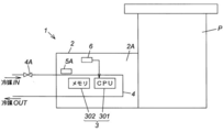
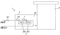
- FIG. 1 is a block diagram of a vacuum pump according to an embodiment of the present invention
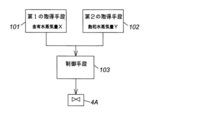
- FIG. 2 is a processing block diagram of a control unit provided in the vacuum pump shown in FIG. 1
- FIG. 3 is provided in the vacuum pump of FIG.
- FIG. 4 is an explanatory diagram of a program configuration example in the case where the first and second acquisition means and the control means shown in FIG. 2 are configured as a CPU processing program in the control unit
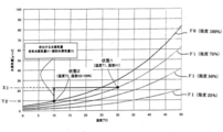
- FIG. 4 shows the amount of water vapor (saturated water vapor amount) with respect to temperature. It is the graph which showed the change. *
- a control unit 1 included in the vacuum pump P of FIG. 1 is used as a means for controlling the vacuum pump P, such as power supply to the vacuum pump P and rotation speed control of the pump rotor.
- the vacuum pump control unit 1 has an amount of water vapor (hereinafter referred to as “water vapor content X”) contained in the gas (air in the present embodiment) present in the box body 2 ⁇ / b> A. ),
- control means 103 for controlling the expression to be satisfied. *
- the allowable water vapor amount for example, a value of 80 to 90% of the saturated water vapor amount can be adopted.
- the contained water vapor amount X and the allowable water vapor amount YS are compared, but the contained water vapor amount X and the saturated water vapor amount Y may be compared.
- the electronic device 3 includes a CPU 301 and storage means 302 such as a memory storing a pump control program and other necessary data.
- the CPU 301 reads and executes the pump control program from the storage means 302.
- the rotor speed of the vacuum pump P is controlled.
- the electronic device 3 also controls the magnetic bearing.
- the electronic device 3 includes a power source. Further, since the rotation speed of the rotor and the control of the magnetic bearing are well known, detailed description thereof is omitted. *
- the cooling pipe 4 is disposed so as to pass through the vicinity of the electronic device 3 (in the example of FIG. 1, in the vicinity of a heating element such as the CPU 301 and the storage means 302), and is cooled outside the vacuum pump control unit 1.
- the cooled refrigerant flows in the cooling pipe 4.
- the cooling pipe 4 is configured to be capable of adjusting the flow rate of the refrigerant flowing through the cooling pipe 4 by providing the variable flow rate valve 4A on the upstream side.
- the refrigerant (cold fluid) flowing through the cooling pipe 4 cold gas or the like may be employed in addition to cooling water. *
- the vacuum pump control unit 1 in FIG. 1 includes a humidity sensor 6 that measures the humidity inside the box body 2A, a first temperature sensor 5A that measures the surface temperature of the cooling pipe 4, and the temperature inside the box body 2A. And a second temperature sensor 5B to be measured. *
- the first acquisition unit 101 in FIG. 2 performs a series of processes using the second temperature sensor 5B and the humidity sensor 6, specifically, for example, during the operation of the vacuum pump control unit 1, A process of measuring the current temperature and humidity inside the box body 2A with the temperature sensor 5B and the humidity sensor 6, and a process of obtaining the water vapor content X in the box body 2A from the measured values (current temperature and humidity); Is included. *
- the second acquisition unit 102 in FIG. 2 uses the first temperature sensor 5A during a series of processes using the first temperature sensor 5A, specifically, for example, during operation of the vacuum pump control unit 1.
- steam amount Y with the measured value (surface temperature) are included.
- the processing in the first and second acquisition units 101 and 102 is, for example, a processing program in the CPU 301 in FIG. 1 or a processing program in a CPU (not shown) provided separately from the CPU 301 (hereinafter referred to as these programs).
- the processing program can be configured as a “CPU processing program”.
- the CPU processing program is, for example, as shown in FIG. 3, (ST1) The inside of the box measured by the second temperature sensor 5B and the humidity sensor 6
- the water vapor content X (X1) is obtained, or the water vapor content X (X1) is calculated using the equation of the water vapor curve F1 and the temperature and humidity read in advance.
- the program configuration includes the process (ST2) to be acquired.
- the data of the water vapor amount curve F1 of FIG. 4 and its formula are stored in the storage means 302 that can be used by the CPU 301 or another CPU.
- the CPU processing program is, for example, as shown in FIG. 3 (ST3), the surface temperature T of the cooling pipe 4 measured by the first temperature sensor 5A.
- ST3 the surface temperature T of the cooling pipe 4 measured by the first temperature sensor 5A.
- the cooling pipe The saturated water vapor amount Y (Y2) at the surface temperature of 4 is obtained, or at the surface temperature using the saturated water vapor curve F0 and the surface temperature T (T2) of the cooling pipe 4 read earlier.
- the data and the equation of the saturated water vapor curve F0 in FIG. 4 are stored in the storage means 302 that can be used by the CPU 301 or another CPU. *
- the control means 103 can also be configured as a CPU processing program in the same manner as the first or second acquisition means 101 and 102 described above.
- the CPU processing program (ST5) sets the allowable water vapor amount YS from the saturated water vapor amount Y (ST5), and (ST6) the first as described above.
- the program configuration includes processing (ST7 and ST8). *
- control means 103 for the process of operating the variable flow rate valve 4A, for example, as shown in FIG. 3, it is determined whether or not (ST6) the contained water vapor amount X (X1) exceeds the allowable water vapor amount YS.
- ST6 the contained water vapor amount X (X1) exceeds the allowable water vapor amount YS
- the cooling pipe 4 is operated in the direction to close the flow rate variable valve 4A.
- the surface temperature of the cooling pipe 4 is adjusted to be increased, and in the vicinity of the cooling pipe 4 ⁇ Conditions >> (Processing Water Vapor X ⁇ Allowable Water Vapor YS) (ST6 YES and ST7) and (ST6 NO and ST8) Containing Water Vapor X (X1) If S is not exceeded, the program configuration includes a process (NO in ST6 and ST8) of continuing the cooling of the electronic device 3 by the cooling pipe 4 without operating the flow rate variable valve 4A of the cooling pipe 4. . *
- the operation in the direction of closing the flow rate variable valve 4A is performed by changing the flow rate from a signal output means (not shown) of the vacuum pump control unit 1 in the CPU processing program.
- a method of incorporating a process of outputting a flow rate setting signal to the valve 4A is conceivable.
- the variable flow rate valve 4A adjusts the flow rate of the refrigerant based on the output flow rate setting signal.
- the saturated water vapor amount is obtained from the surface temperature of a water-cooled tube (cooling means) that is a predetermined part inside the box, but is not limited to this, and the part that is likely to condense as another predetermined part. You may acquire from the temperature of. *
- the cooling means is installed inside the box, but is not limited thereto, and may be a structure installed outside the box and cooling the inside of the box.
- FIG. 5 is an equipment configuration diagram of a vacuum pump according to another embodiment of the present invention.
- FIG. 6 shows a control unit (vacuum pump control unit 1) provided in the vacuum pump of FIG. It is explanatory drawing of the example of a program structure in case the 1st and 2nd acquisition means and a control means are comprised as a CPU processing program. *
- the vacuum pump control unit 1 of FIG. 5 also has a configuration in which an electronic device 3 that controls the vacuum pump P and a cooling pipe 4 that cools the electronic device 3 are housed in the box body 2A.
- the vacuum control unit 1 of FIG. 5 is also saturated at the surface temperature of the cooling pipe 4 and the processing block configuration of FIG. 2, that is, the first acquisition means 101 for acquiring the water vapor content X in the box body 2A.
- the second obtaining means 102 for obtaining the water vapor amount Y, the allowable water vapor amount YS is set from the saturated water vapor amount Y, and based on the comparison result between the contained water vapor amount X and the allowable water vapor amount YS, And a control means 103 that controls the condition of the ⁇ conditional expression >> in the vicinity of the cooling pipe 4 by operating the flow rate variable valve 4A and adjusting the surface temperature of the cooling pipe 4.
- the vacuum pump control unit 1 shown in FIG. 5 is different from the vacuum pump control unit 1 shown in FIG. 1 as follows.
- Other configurations such as the second acquisition means 102 and the control means 103 are concrete. Since the configuration is the same as that of the vacuum pump control unit 1 of FIG. 1, the same reference numerals are given to the same members, and detailed descriptions thereof are omitted. *
- the vacuum pump control unit 1 in FIG. 5 includes a humidity sensor 6 that measures the humidity inside the box body 2A and a temperature sensor 5A that measures the surface temperature of the cooling pipe 4.
- a temperature sensor that measures the temperature of 2A is not provided.
- the storage means 302 in the vacuum pump control unit 1 in FIG. 5 stores the amount of water vapor inside the box body 2A before shipment of the vacuum pump control unit 1 as the initial water vapor amount.
- the correction value of the water vapor amount corresponding to the temperature or humidity of 2A is also stored.
- the first acquisition means 101 in the vacuum pump control unit 1 of FIG. 5 includes, for example, a process of measuring the humidity inside the box 2A with the humidity sensor 6 while the vacuum pump control unit 1 is in operation.
- the first acquisition unit 101 in the vacuum pump control unit 1 of FIG. 5 can also be configured as a CPU processing program.
- the CPU processing program reads the humidity inside the box 2A measured by the humidity sensor 6 (ST9), and reads the humidity read from ST9 and the storage means 302.
- the temperature of the box interior 2A is acquired by referring to the data of the water vapor amount curve F1 shown in FIG.
- the data of the water vapor amount curve F1 and the formula thereof in FIG. 4 are stored in the storage unit 302 that can be used by the CPU 301 or another CPU.
- the amount of water vapor absorbed by the substrate of the electronic device 3 is increased, and the amount of water vapor present as water vapor in the box interior 2A is reduced.
- the actual temperature is expected to be lower than the value obtained from the initial water vapor amount.
- the humidity decreases, the amount of water vapor released from the substrate of the electronic device 3 increases. Therefore, the actual temperature is expected to be higher than the value obtained from the initial water vapor amount.
- the amount of water vapor determined in ST11 may be determined in consideration of the change in the amount of water vapor contained, instead of directly calculating from the humidity read in ST9 and the temperature determined in ST10. *
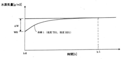
- FIG. 7 is an explanatory diagram of the correction value of the water vapor amount.
- Curve 1 in the figure shows that the inside of the box body 2A from the electronic device 3 or the like when the inside 2A of the box body is at a predetermined temperature (TS1) and a predetermined humidity (HS1) since the vacuum pump control unit 1 is started (h0).
- the correction value may be set to zero. In this case, the process of adding the correction value to the initial water vapor amount W0 may be omitted.
- the vacuum pump control unit 1 of FIG. 5 described above also satisfies the ⁇ conditional expression> (containing water vapor amount X ⁇ allowable water vapor amount YS) in the vicinity of the cooling pipe 4. Condensation is unlikely to occur, and it is possible to effectively prevent problems such as failure of electronic devices due to water droplets due to condensation.
- FIG. 8 is an apparatus configuration diagram of a vacuum pump according to another embodiment of the present invention.
- FIG. 9 shows a control unit (vacuum pump control unit 1) provided in the vacuum pump of FIG. It is explanatory drawing of the example of a program structure in case the 1st and 2nd acquisition means and a control means are comprised as a CPU processing program. *
- the vacuum pump control unit 1 of FIG. 8 also has a configuration in which an electronic device 3 that controls the vacuum pump P and a cooling pipe 4 that cools the electronic device 3 are housed in the box body 2A. Further, the vacuum control unit 1 of FIG. 8 is also saturated in the processing block configuration of FIG. 2, that is, the first acquisition means 101 for acquiring the water vapor content X in the box body 2 ⁇ / b> A and the surface temperature of the cooling pipe 4.
- the second obtaining means 102 for obtaining the water vapor amount Y, the allowable water vapor amount YS is set from the saturated water vapor amount Y, and based on the comparison result between the contained water vapor amount X and the allowable water vapor amount YS, And a control means 103 that controls the condition of the ⁇ conditional expression >> in the vicinity of the cooling pipe 4 by operating the flow rate variable valve 4A and adjusting the surface temperature of the cooling pipe 4.
- the vacuum pump control unit 1 shown in FIG. 8 is different from the vacuum pump control unit 1 shown in FIG. 1 as follows. Other configurations such as the second acquisition unit 102 and the control unit 103 are described in detail. Since the configuration is the same as that of the vacuum pump control unit 1 of FIG. 1, the same reference numerals are given to the same members, and detailed descriptions thereof are omitted. *
- the vacuum pump control unit 1 in FIG. 8 includes the first temperature sensor 5A described above (which measures the surface temperature of the cooling pipe 4) and a humidity sensor that measures the humidity in the vicinity of the cooling pipe 4. 7, a humidity sensor 6 for measuring the humidity inside the box body 2A shown in FIG. 1 and FIG. 5 and a temperature sensor for measuring the temperature inside the box body 2A (the second sensor described above). Temperature sensor 5B) is not provided. *
- the first acquisition means 101 in the vacuum pump control unit 1 of FIG. 8 includes, for example, a process of measuring the humidity in the vicinity of the cooling pipe 4 with the humidity sensor 7 while the vacuum pump control unit 1 is in operation. And a process of acquiring the amount of water vapor X contained in the box interior 2A from the humidity and the temperature of the cooling pipe 4 measured by the temperature sensor 5A.
- the first acquisition unit 101 in the vacuum pump control unit 1 of FIG. 8 can also be configured as a CPU processing program.
- the CPU processing program reads the humidity in the vicinity of the cooling pipe 4 measured by the humidity sensor 7 (ST13), the temperature read in ST3, and the humidity read in ST13. 4 is used to obtain the water vapor content by referring to the data of the water vapor curve F1 shown in FIG. 4, or the water vapor content using the equation of the water vapor curve F1 and the previously read temperature and humidity. And a process for calculating and acquiring (ST14).
- the data of the water vapor amount curve F1 of FIG. 4 and its formula are stored in the storage means 302 that can be used by the CPU 301 or another CPU. *
- the vacuum pump control unit 1 of FIG. 8 described above also satisfies the above ⁇ conditional expression> (containing water vapor amount X ⁇ allowable water vapor amount YS) in the vicinity of the cooling pipe 4. Condensation is unlikely to occur, and it is possible to effectively prevent problems such as failure of electronic devices due to water droplets due to condensation. *
- the box interior 2A is filled with air, but the present invention is not limited to this example, and the box interior is filled with a gas other than air.
- the present invention can also be applied to a configuration in which 2A is satisfied. *
- an ON / OFF type opening / closing valve can be used as the valve of the cooling pipe 4 instead of the flow rate variable valve 4 ⁇ / b> A.
- the temperature change of the cooling pipe 4 becomes more severe than in the usage example of the flow rate variable valve 4A. Therefore, the open / close operation of the open / close valve frequently occurs, and the life of the open / close valve may be shortened.
- the thickness of the cooling pipe 4 is increased, the constituent material of the cooling pipe 4 is a material having poor heat conduction, or the temperature control accuracy of the cooling pipe 4 is increased. Is set so that the temperature change of the cooling pipe 4 becomes dull.
- the CPU 301 and the storage means 302 are described as being incorporated in the electronic device 3 that controls the vacuum pump P.
- the present invention is not limited to this example, and can be applied to a configuration having a control means for adjusting only the surface temperature of the cooling pipe separately from the electronic device 3 for controlling the vacuum pump P. With such a configuration, there is an advantage that the surface temperature of the cooling pipe can be controlled regardless of the operation state of the vacuum pump control unit.
- the present invention is not limited to the embodiments described above, and many modifications can be made by those having ordinary knowledge in the art within the technical idea of the present invention.
- the amount of water vapor contained is obtained by the first obtaining means 101, and the temperature at which the water vapor amount becomes 100% is calculated by referring to the data of the water vapor amount curve shown in FIG.
- the valve may be controlled so that the temperature does not fall below this temperature.
Landscapes
- Engineering & Computer Science (AREA)
- Mechanical Engineering (AREA)
- General Engineering & Computer Science (AREA)
- Physics & Mathematics (AREA)
- Thermal Sciences (AREA)
- Non-Positive Displacement Air Blowers (AREA)
- Control Of Positive-Displacement Pumps (AREA)
- Compressors, Vaccum Pumps And Other Relevant Systems (AREA)
Abstract
【課題】コントロールユニットを備えた真空ポンプにおいて、冷却管の表面やその周辺において結露を確実に防止することができ、結露による水滴で電子機器が故障するなどのトラブルを効果的に減らすことができるようにした真空ポンプを提供する。【解決手段】コントロールユニット(真空ポンプコントロールユニット1)は、箱体内部2Aの含有水蒸気量Xを取得する第1の取得手段101と、冷却管4の表面温度での飽和水蒸気量Yを取得する第2の取得手段102と、前記飽和水蒸気量Yから許容水蒸気量YSを設定し、前記含有水蒸気量Xと前記許容水蒸気量YSとの比較結果に基づいて冷却管4の流量可変バルブ4Aを操作し、冷却管4の表面温度を調節することにより、冷却管4近傍で後記《条件式》が満たされるように制御する制御手段101と、を備えるものとする。《条件式》含有水蒸気量X<許容水蒸気量YS
Description
本発明は、電子機器を冷却管で冷却するタイプのコントロールユニットを備えた真空ポンプに関し、特に、冷却管の表面やその周辺において結露を防止することができ、結露による水滴で電子機器が故障するなどのトラブルを効果的に減らすことができるようにしたものである。
従来、真空ポンプへの電力供給やポンプロータの回転数制御などは、真空ポンプに付属の真空ポンプコントロールユニットで行っている。この種の真空ポンプコントロールユニットとしては、例えば、特許文献1に開示の真空ポンプ用電源装置が知られている。
特許文献1に開示の真空ポンプ用電源装置(3)は、同文献1の図1に図示の通り、その装置内部に、CPU(8)などの電子機器と冷却管(5)を収容し、冷却管(5)で電子機器を冷却する構成になっている。
また、この特許文献1に開示の真空ポンプ用電源装置(3)では、同文献1の図1に図示の温度センサ(12)で冷却管(5)の温度を計測し、計測した冷却管(5)の温度に基づきCPU(8)が冷却管(5)のバルブ(6)を開閉することにより、冷却管(5)が結露しない温度を保つように制御している。
しかし、特許文献1に開示の真空ポンプ用電源装置(3)によると、前記のように冷却管(5)の温度を計測しているだけで、同装置内部の湿度を計測していないから、同装置内部での結露を防止し得ず、冷却管(5)の表面やその周辺において結露が発生する可能性があり、結露による水滴で電子機器が故障するなどのトラブルを効果的に減らすことはできない。
また、特許文献1に開示の真空ポンプ用電源装置(3)では、同文献1の図4に図示の結露センサ(7)で同装置内部の結露を検知しているが、この結露の検知は、予め実験により求めた露点テーブルによるものであり、露点テーブルの作成では、真空ポンプ用電源装置(3)の組立環境の如何により同装置内部の初期の水蒸気量が異なるなど、同装置の組立条件も考慮しなければならず、正確に結露を検知できる露点テーブルの作成は困難であることより、冷却管(5)の表面やその周辺において結露が発生する可能性があり、結露による水滴で電子機器が故障するなどのトラブルを効果的に減らすことはできない。
なお、前記カッコ内の符号は特許文献1で使用されている符号である。
本発明は、前記問題点を解決するためになされたもので、その目的は、コントロールユニットを備えた真空ポンプにおいて、冷却管の表面やその周辺において結露を防止することができ、結露による水滴で電子機器が故障するなどのトラブルを効果的に減らすことができるようにした真空ポンプを提供することである。
前記目的を達成するために、本発明は、真空ポンプにおいて、電子部品を実装した電子回路を箱体内部に配置し、前記真空ポンプを駆動制御するコントロールユニットと、前記コントロールユニットを冷却する冷却手段と、前記箱体内部の含有水蒸気量を取得する第1の取得手段と、前記箱体内部の飽和水蒸気量を取得する第2の取得手段と、前記含有水蒸気量と前記飽和水蒸気量との比較結果に基づいて、前記冷却手段を操作し、前記箱体内部の温度を調整することにより、下記《条件式》が満たされるように制御する制御手段と、を備えたことを特徴とする。 《条件》 含有水蒸気量<飽和水蒸気量
前記本発明において、前記制御手段は、前記飽和水蒸気量から許容水蒸気量を設定し、前記含有水蒸気量と該許容水蒸気量との比較結果に基づいて前記冷却手段を操作し、前記箱体内部の温度を調節することにより、前記《条件式》が満たされるように制御することを特徴としてもよい。
前記本発明において、前記飽和水蒸気量は、前記箱体内部の所定部の表面温度での飽和水蒸気量であることを特徴としてもよい。
前記本発明において、前記冷却手段は、内部を水または他の冷熱流体が流れる冷却管であることを特徴としてもよい。
また、前記本発明において、前記第2の取得手段は、前記所定部の前記表面温度を計測する第1の温度センサを備え、前記第1の温度センサで計測した前記表面温度での前記飽和水蒸気量を取得する処理を行うことを特徴としてもよい。
前記本発明において、前記第1の取得手段は、前記箱体内部の湿度を計測する湿度センサと、前記箱体内部の温度を計測する第2の温度センサと、を備え、前記第2の温度センサと前記湿度センサで前記箱体内部の前記温度と前記湿度を計測する処理と、その温度及び湿度から前記箱体内部の前記含有水蒸気量を取得する処理を行うことを特徴としてもよい。
前記本発明において、前記第1の取得手段は、前記箱体内部の湿度を計測する湿度センサと、前記真空ポンプ出荷前における前記箱体内部の水蒸気量を初期水蒸気量として格納するとともに、前記箱体内部の温度または前記湿度に対応する水蒸気量の補正値を格納した記憶手段と、を備え、前記湿度センサで前記箱体内部の前記湿度を計測する処理と、その湿度及び前記初期水蒸気量を参考にして前記箱体内部の前記温度を取得する処理と、前記補正値を前記湿度と前記温度から求められた水蒸気量に加算し、その加算値を前記箱体内部の前記含有水蒸気量として取得する処理と、を含むことを特徴としても良い。
前記本発明において、前記第1の取得手段は、前記所定部の近傍の湿度を計測する湿度センサを備え、前記第1の温度センサと前記湿度センサで計測した前記表面温度及び前記湿度から前記含有水蒸気量を取得する処理を行うことを特徴としてもよい。
前記本発明において、前記冷却管の内部を流れる水または他の冷熱流体の流量を調整するバルブを備え、前記制御手段は、前記バルブの開閉を操作することにより、前記箱体内部の温度を調節することを特徴としてもよい。
前記本発明において、前記バルブは、開口面積を任意に変更できる流量可変バルブであることを特徴としてもよい。
前記本発明において「箱体内部の含有水蒸気量」とは、箱体内部に存在する気体が含有している水蒸気量を意味し、気体は空気に限定されない。
本発明によると、前記の通り、前記冷却管近傍で前記《条件式》(含有水蒸気量<飽和水蒸気量)が満たされるように制御する構成を採用したため、冷却管の表面やその周辺において結露を防止することができ、結露による水滴で電子機器が故障するなどのトラブルを効果的に減らすことができる。
以下、本発明を実施するための最良の形態について、添付した図面を参照しながら詳細に説明する。
図1は、本発明の一実施形態である真空ポンプの機器構成図、図2は、図1に示した真空ポンプが備えるコントロールユニットの処理ブロック図、図3は、図1の真空ポンプが備えるコントロールユニットにおいて、図2に示した第1及び第2の取得手段並びに制御手段をCPU処理プログラムとして構成する場合のプログラム構成例の説明図、図4は、温度に対する水蒸気量(飽和水蒸気量)の変化を示したグラフ図である。
図1の真空ポンプPが備えるコントロールユニット1(以下「真空ポンプコントロールユニット1」という)は、真空ポンプPへの電力供給やポンプロータの回転数制御など、真空ポンプPを制御する手段として用いられるものであって、箱体2の内側空間2A(以下「箱体内部2A」という)に、真空ポンプPを制御する電子機器3、及び、該電子機器3を冷却する冷却管4(冷却手段)を収容した構成になっている。
また、この真空ポンプコントロールユニット1は、図2に示したように、箱体内部2Aに存在する気体(本実施形態では、空気)が含有している水蒸気量(以下「含有水蒸気量X」という)を取得する第1の取得手段101と、冷却管4の表面温度での飽和水蒸気量Yを取得する第2の取得手段102と、前記飽和水蒸気量Yから許容水蒸気量YSを設定し、前記含有水蒸気量Xと前記許容水蒸気量YSとの比較結果に基づいて冷却管4の流量可変バルブ4Aを操作し、冷却管4の表面温度を調節することにより、前記冷却管4近傍で下記《条件式》が満たされるように制御する制御手段103と、を備えている。
《条件式》 含有水蒸気量X<許容水蒸気量YS
前記許容水蒸気量としては、例えば飽和水蒸気量の80~90%の値を採用することができる。
本実施形態では、前記含有水蒸気量Xと前記許容水蒸気量YSを比較したが、前記含有水蒸気量Xと前記飽和水蒸気量Yを比較しても良い。
前記電子機器3は、CPU301、並びに、ポンプ制御プログラムやその他の必要なデータを格納したメモリ等の記憶手段302から構成されており、かつ、CPU301が記憶手段302からポンプ制御プログラムを読み出し実行することにより、真空ポンプPのロータ回転数などを制御する。また、真空ポンプPのロータが磁気軸受により磁気浮上支持される場合、この電子機器3はその磁気軸受も制御する。なお、前記電子機器3は電源も含む。また、ロータ回転数や磁気軸受の制御などについては周知であるため、その詳細な説明は省略する。
前記冷却管4は、前記電子機器3の近傍(図1の例ではCPU301や記憶手段302のような発熱体の近傍)を通過するように配置されるとともに、真空ポンプコントロールユニット1の外部で冷やされた冷媒が冷却管4の内部を流れるように構成してある。またこの冷却管4は、その上流側に前記流量可変バルブ4Aを備えることによって、冷却管4の内部を流れる冷媒の流量を調整できる構成になっている。冷却管4に流す冷媒(冷熱流体)としては冷却水のほか、冷温ガスなどを採用してもよい。
また、図1の真空ポンプコントロールユニット1は、箱体内部2Aの湿度を計測する湿度センサ6と、冷却管4の表面温度を計測する第1の温度センサ5Aと、箱体内部2Aの温度を計測する第2の温度センサ5Bと、を備えている。
そして、図2の前記第1の取得手段101は、第2の温度センサ5Bと湿度センサ6を使用した一連の処理、具体的には、例えば真空ポンプコントロールユニット1の稼働中に、第2の温度センサ5Bと湿度センサ6で箱体内部2Aの現在の温度と湿度を計測する処理と、その計測値(現在の温度及び湿度)から箱体内部2Aの含有水蒸気量Xを取得する処理と、を含んでいる。
また、図2の前記第2の取得手段102は、第1の温度センサ5Aを使用した一連の処理、具体的には、例えば真空ポ
ンプコントロールユニット1の稼働中に、第1の温度センサ5Aで冷却管4の表面温度を計測する処理と、その計測値(表面温度)での飽和水蒸気量Yを取得する処理と、を含んでいる。
ンプコントロールユニット1の稼働中に、第1の温度センサ5Aで冷却管4の表面温度を計測する処理と、その計測値(表面温度)での飽和水蒸気量Yを取得する処理と、を含んでいる。
前記第1及び第2の取得手段101、102での前記処理は、例えば、図1のCPU301での処理プログラムや、そのCPU301とは別に設けられた図示しないCPUでの処理プログラム(以下、これらの処理プログラムを「CPU処理プログラム」という)として構成することができる。
前記第1の取得手段101をCPU処理プログラムとして構成する場合、そのCPU処理プログラムは、例えば図3に示したように、(ST1)第2の温度センサ5Bと湿度センサ6で計測した箱体内部2Aの温度T(T1)と湿度H(H1)を読み取る処理(ST1)と、(ST2)先に読み取った温度T(T1)と湿度H(H1)を用いて図4に示した水蒸気量曲線F1のデータを参照することで、含有水蒸気量X(X1)を取得する、又は、前記水蒸気曲線F1の式と先に読み取った温度及び湿度とを使用して含有水蒸気量X(X1)を算出取得する処理(ST2)と、を含んだプログラム構成になる。この場合、図4の水蒸気量曲線F1のデータやその式は、CPU301又は別のCPUが利用できる記憶手段302に格納しておく。
前記第2の取得手段102をCPU処理プログラムとして構成する場合、そのCPU処理プログラムは、例えば図3に示したように、(ST3)第1の温度センサ5Aで計測した冷却管4の表面温度T(T2)を読み取る処理(ST3)と、(ST4)先に読み取った冷却管4の表面温度T(T2)で図4に示した飽和水蒸気量曲線F0のデータを参照することにより、前記冷却管4の表面温度での飽和水蒸気量Y(Y2)を取得する、または、前記飽和水蒸気曲線F0の式と先に読み取った冷却管4の表面温度T(T2)とを使用してその表面温度での飽和水蒸気量Y(Y2)を算出取得する処理(ST4)と、を含んだプログラム構成になる。この場合も、図4の飽和水蒸気量曲線F0のデータやその式は、CPU301又は別のCPUが利用できる記憶手段302に格納しておく。
前記制御手段103もまた、先に説明した第1又は第2の取得手段101、102と同じく、CPU処理プログラムとして構成することができる。この場合、そのCPU処理プログラムは、例えば図3に示したように、(ST5)前記飽和水蒸気量Yから許容水蒸気量YSを設定する処理(ST5)と、(ST6)前記のように第1の取得手段101で取得した含有水蒸気量X(X1)と許容水蒸気量YSとを比較する処理(ST6)と、(ST7及びST8)その比較結果に基づいて冷却管4の流量可変バルブ4Aを操作する処理(ST7及びST8)と、を含んだプログラム構成になる。
前記制御手段103において、前記流量可変バルブ4Aを操作する処理については、例えば図3に示したように、(ST6)含有水蒸気量X(X1)が許容水蒸気量YSを越えたか否かを判定する処理(ST6)と、(ST6のYES及びST7)含有水蒸気量X(X1)が許容水蒸気量YSを越えた場合に、冷却管4の流量可変バルブ4Aを閉める方向に操作し、冷却管4を流れる冷媒の流量を減らすこと(冷却機能の低下)、あるいは、その流量を0に設定すること(冷却中止)により、冷却管4の表面温度を高める方向に調節して、冷却管4近傍で前記《条件》(含有水蒸気量X<許容水蒸気量YS)が満たされるようにする処理(ST6のYES及びST7)と、(ST6のNO及びST8)含有水蒸気量X(X1)が許容水蒸気量YSを越えていない場合は、冷却管4の流量可変バルブ4Aを操作せず、冷却管4による電子機器3の冷却を継続する処理(ST6のNO及びST8)と、を含んだプログラム構成になる。
前記制御手段103を前述のCPU処理プログラムとして構成する場合において、流量可変バルブ4Aを閉める方向への操作は、そのCPU処理プログラムの中に、真空ポンプコントロールユニット1の図示しない信号出力手段から流量可変バルブ4Aに対して流量設定信号を出力するという処理を組み込む方法が考えられる。この場合、流量可変バルブ4Aは出力された流量設定信号に基づいて冷媒の流量を調整する。
以上説明した図1の真空ポンプコントロールユニット1にあっては、冷却管4近傍では必ず前記《条件式》(含有水蒸気量X<許容水蒸気量YS)が満たされるから、冷却管4の表面やその周辺において結露が生じにくく、結露による水滴で電子機器が故障するなどの不具合を効果的に防止することができる。
本実施形態では、飽和水蒸気量は、箱体内部の所定部である水冷管(冷却手段)の表面温度から取得したが、これに限定されず、その他の所定部として結露しやすいと思われる個所の温度から取得してもよい。
本実施形態では、冷却手段は、箱体内部に設置されているものとしたが、これに限定されず、箱体外部に設置され、箱体内部を冷却する構造であってもよい。
図5は、本発明の他の実施形態である真空ポンプの機器構成図であり、図6は、図5の真空ポンプが備えるコントロールユニット(真空ポンプコントロールユニット1)において、図2に示した第1及び第2の取得手段並びに制御手段をCPU処理プログラムとして構成する場合のプログラム構成例の説明図である。
図5の真空ポンプコントロールユニット1も、箱体内部2Aに、真空ポンプPを制御する電子機器3と、該電子機器3を冷却する冷却管4を収容した構成になっている。また、この図5の真空コントロールユニット1も、図2の処理ブロック構成、すなわち、箱体内部2Aの含有水蒸気量Xを取得する第1の取得手段101と、冷却管4の表面温度での飽和水蒸気量Yを取得する第2の取得手段102と、前記飽和水蒸気量Yから許容水蒸気量YSを設定し、前記含有水蒸気量Xと前記許容水蒸気量YSとの比較結果に基づいて冷却管4の流量可変バルブ4Aを操作し、冷却管4の表面温度を調節することにより、冷却管4近傍で前記《条件式》が満たされるように制御する制御手段103と、を備えている。
この図5の真空ポンプコントロールユニット1が図1の真空ポンプコントロールユニット1と相違する点は以下の通りであり、それ以外の構成、例えば第2の取得手段102や制御手段103などの具体的な構成は、図1の真空ポンプコントロールユニット1と同様であるため、同一部材には同一符号を付し、その詳細説明は省略する。
(相違点1) 図5の真空ポンプコントロールユニット1は、箱体内部2Aの湿度を計測する湿度センサ6と、冷却管4の表面温度を計測する温度センサ5Aと、を備えるが、箱体内部2Aの温度を計測する温度センサ(先に説明した第2の温度センサ5Bを参照)は備えていない。
(相違点2) 図5の真空ポンプコントロールユニット1における記憶手段302には、真空ポンプコントロールユニット1出荷前における箱体内部2Aの水蒸気量を初期水蒸気量として格納してあり、また、箱体内部2Aの温度または湿度に対応する水蒸気量の補正値も格納してある。
(相違点3) 図5の真空ポンプコントロールユニット1における第1の取得手段101は、例えばその真空ポンプコントロールユニット1の稼動中に、湿度センサ6で箱体内部2Aの湿度を計測する処理と、その湿度及び前記初期水蒸気量を参考にして箱体内部2Aの温度を取得する処理と、前記補正値を前記温度と前記湿度によって求められた水蒸気量に加算し、その加算値を箱体内部2Aの含有水蒸気量として取得する処理と、を含んでいる。
図5の真空ポンプコントロールユニット1における第1の取得手段101も、CPU処理プログラムとして構成することができる。この場合、そのCPU処理プログラムは、例えば図6に示したように、湿度センサ6で計測した箱体内部2Aの湿度を読み取る処理(ST9)と、前記ST9で読み取った湿度及び記憶手段302から読み取った前記初期水蒸気量を用いて図4に示した水蒸気量曲線F1のデータを参照することにより箱体内部2Aの温度を取得する、又は、前記水蒸気曲線F1の式と前記ST9で読み取った湿度と記憶手段302から読み取った前記初期水蒸気量とを用いて温度を算出取得する処理(ST10)と、前記ST9で読み取った湿度と前記ST10で取得した温度とから水蒸気量を求める処理(ST11)と、前記ST10で取得した温度または前記ST9で読み取った湿度に対応する補正値を記憶手段302から読み取るとともに、この読み取った補正値を前記ST11で求めた水蒸気量に加算し、その加算値を前記箱体内部2Aの含有水蒸気量として取得する処理(ST12)と、を含んだプログラム構成になる。この場合、図4の水蒸気量曲線F1のデータやその式は、CPU301又は別のCPUが利用できる記憶手段302に格納しておくものとする。
ここで、前記ST11の水蒸気量を求める処理について、補足する。 ST10で温度を取得する際、箱体内部2Aの現在の含有水蒸気量が初期水蒸気量から変わらないものとしているが、後述するように箱体内部2Aの湿度によっても変化するため、湿度の変化による含有水蒸気量の変化を見越して、ST11の水蒸気量を求めることも出来る。
例えば、温度変化が前提で湿度が高くなるような変化をした場合、電子機器3の基板等に吸湿される水蒸気量は増え、箱体内部2A内に水蒸気として存在する含有水蒸気量は少なくなるため、実際の温度は、初期水蒸気量で求められる値よりも低い値となると予想される。これとは逆に、湿度が低くなると、電子機器3の基板等から放湿される水蒸気量は増えるため、実際の温度は、初期水蒸気量で求められる値よりも高い値となると予想される。
そのため、ST11で求められる水蒸気量は、ST9で読み取った湿度とST10で求められた温度からそのまま算出するのではなく、上記含有水蒸気量の変化を考慮して求めても良い。
なお、図6において、ST3からST8までの処理は、先に説明した図3のものと同じであるため、その詳細説明は省略する。
図7は、水蒸気量の補正値の説明図である。同図中の曲線1は、真空ポンプコントロールユニット1起動時(h0)から箱体内部2Aが所定温度(TS1)、所定湿度(HS1)であるときに、電子機器3などから箱体内部2A内に放出される吸湿水分量ΔWと水蒸気量W0との加算値、すなわち箱体内部2の含有水蒸気量X(=W0+ΔW)を時系列で示したイメージ図である。
前記曲線1を参照すると、起動時(h0)から時刻(h1)までの間は、吸湿水分量ΔWの放出により、箱体内部2A全体の含有水蒸気量X(=W0+ΔW)の増加が見られる。しかし、時刻(h1)以降は、吸湿水分量ΔWの放出が所定値に安定することで、箱体内部2A全体の含有水蒸気量X(=W0+ΔW)も所定値に安定している。
以上のことから、図5の真空ポンプコントロールユニット1における第1の取得手段101では、箱体内部2Aの温度がTS1、湿度がHS1以外であっても、前記補正値を参考にして、その温度および湿度に対応する含有水蒸気量の補正値として、図7に示したΔW(吸湿水分量)を使用している。また、TS1、HS1だけでなく、幾つかの条件で補正値を求めておいて、それら組み合わせの中から、補正値を類推してもよい。
ところで、吸湿水分量ΔWの数値が初期水蒸気量W0の有効桁数より小さいなど、初期水蒸気量W0に比べて吸湿水分量ΔWが無視できるほど小さい場合は、前記補正値を0としてもよい。この場合は、初期水蒸気量W0に前記補正値を加算する処理は省略してよい。
以上説明した図5の真空ポンプコントロールユニット1もまた、冷却管4近傍では必ず前記《条件式》(含有水蒸気量X<許容水蒸気量YS)が満たされるから、冷却管4の表面やその周辺において結露が生じにくく、結
露による水滴で電子機器が故障するなどの不具合を効果的に防止することができる。
露による水滴で電子機器が故障するなどの不具合を効果的に防止することができる。
図8は、本発明の他の実施形態である真空ポンプの機器構成図であり、図9は、図8の真空ポンプが備えるコントロールユニット(真空ポンプコントロールユニット1)において、図2に示した第1及び第2の取得手段並びに制御手段をCPU処理プログラムとして構成する場合のプログラム構成例の説明図である。
図8の真空ポンプコントロールユニット1も、箱体内部2Aに、真空ポンプPを制御する電子機器3と、該電子機器3を冷却する冷却管4を収容した構成になっている。また、この図8の真空コントロールユニット1も、図2の処理ブロック構成、すなわち、箱体内部2Aの含有水蒸気量Xを取得する第1の取得手段101と、冷却管4の表面温度での飽和水蒸気量Yを取得する第2の取得手段102と、前記飽和水蒸気量Yから許容水蒸気量YSを設定し、前記含有水蒸気量Xと前記許容水蒸気量YSとの比較結果に基づいて冷却管4の流量可変バルブ4Aを操作し、冷却管4の表面温度を調節することにより、冷却管4近傍で前記《条件式》が満たされるように制御する制御手段103と、を備えている。
この図8の真空ポンプコントロールユニット1が図1の真空ポンプコントロールユニット1と相違する点は以下の通りであり、それ以外の構成、例えば第2の取得手段102や制御手段103などの具体的な構成は、図1の真空ポンプコントロールユニット1と同様であるため、同一部材には同一符号を付し、その詳細説明は省略する。
(相違点1) 図8の真空ポンプコントロールユニット1は、先に説明した第1の温度センサ5A(冷却管4の表面温度を計測するもの)と、冷却管4近傍の湿度を計測する湿度センサ7を備えているが、図1や図5に示されている箱体内部2Aの湿度を計測する湿度センサ6と、箱体内部2Aの温度を計測する温度センサ(先に説明した第2の温度センサ5Bを参照)は備えていない。
(相違点2) 図8の真空ポンプコントロールユニット1における第1の取得手段101は、例えばその真空ポンプコントロールユニット1の稼動中に、湿度センサ7で冷却管4近傍の湿度を計測する処理と、その湿度及び温度センサ5Aで計測した冷却管4の温度から箱体内部2Aの含有水蒸気量Xを取得する処理と、を含んでいる。
図8の真空ポンプコントロールユニット1における第1の取得手段101も、CPU処理プログラムとして構成することができる。この場合、そのCPU処理プログラムは、例えば図9に示したように、湿度センサ7で計測した冷却管4近傍の湿度を読み取る処理(ST13)と、ST3で読み取った温度とST13で読み取った湿度を用いて図4に示した水蒸気量曲線F1のデータを参照することで、含有水蒸気量を取得する、又は、前記水蒸気曲線F1の式と先に読み取った温度及び湿度とを使用して含有水蒸気量を算出取得する処理(ST14)と、を含んだプログラム構成になる。この場合、図4の水蒸気量曲線F1のデータやその式は、CPU301又は別のCPUが利用できる記憶手段302に格納しておく。
なお、図9において、ST3からST8までの処理は、先に説明した図3のものと同じであるため、その詳細説明は省略する。
以上説明した図8の真空ポンプコントロールユニット1もまた、冷却管4近傍では必ず前記《条件式》(含有水蒸気量X<許容水蒸気量YS)が満たされるから、冷却管4の表面やその周辺において結露が生じにくく、結露による水滴で電子機器が故障するなどの不具合を効果的に防止することができる。
図1又は図5又は図8の真空ポンプコントロールユニット1の例では、箱体内部2Aが空気で満たされているが、本発明は、その例に限定されず、空気以外の気体で箱体内部2Aが満たされている構成にも適用することができる。
図1又は図5又は図8の真空ポンプコントロールユニット1の例において、冷却管4のバルブとして、流量可変バルブ4Aに代えて、ON/OFF形式の開閉バルブを使用することも可能である。しかし、この使用例では、流量可変バルブ4Aの使用例に比べ、冷却管4の温度変化が激しくなるため、開閉バルブでの開閉動作が頻繁に起こり、開閉バルブの寿命が短くなるおそれがある。このような不具合を防止するために、前記使用例の場合は、冷却管4の肉厚を厚くしたり、冷却管4の構成材料を熱伝導の悪い材料としたり、冷却管4の温度制御精度を低くすることによって、冷却管4の温度変化が鈍くなるように設定すればよい。
図1又は図5又は図8の真空ポンプコントロールユニット1の例では、CPU301および記憶手段302は、真空ポンプPを制御する電子機器3の中に組込まれた説明をしているが、本発明は、その例に限定されず、真空ポンプPを制御する電子機器3とは別に、前記冷却管の表面温度のみを調節する制御手段をもつ構成にも適用することができる。このような構成では、真空ポンプコントロールユニットの稼動状況に関わらず、冷却管の表面温度を制御できるメリットがある。
本発明は、以上説明した実施形態に限定されるものではなく、本発明の技術的思想内で当分野において通常の知識を有する者により多くの変形が可能である。例えば、第1の取得手段101で含有水蒸気量を取得し、図4に示した水蒸気量曲線のデータを参照することで、その水蒸気量が湿度100%になる温度を算出し、冷却管4の温度がこの温度以下にならないようにバルブを制御しても良い。
1 真空ポンプコントロールユニット2 箱体2A 箱体内部3 電子機器4 冷却管4A 流量可変バルブ5A 第1の温度センサ5B 第2の温度センサ6 湿度センサ7 湿度センサ101 第1の取得手段102 第2の取得手段103 制御手段301 CPU302 記憶手段F0 飽和水蒸気量曲線F1 水蒸気量曲線P 真空ポンプX 含有水蒸気量Y 飽和水蒸気量YS 許容水蒸気量
Claims (11)
- 真空ポンプであって、 電子部品を実装した電子回路を箱体内部に配置し、前記真空ポンプを駆動制御するコントロールユニットと、 前記コントロールユニットを冷却する冷却手段と、 前記箱体内部の含有水蒸気量を取得する第1の取得手段と、 前記箱体内部の飽和水蒸気量を取得する第2の取得手段と、 前記含有水蒸気量と前記飽和水蒸気量との比較結果に基づいて、前記冷却手段を操作し、前記箱体内部の温度を調整することにより、下記《条件式》が満たされるように制御する制御手段と、 を備えたことを特徴とする真空ポンプ。 《条件》 含有水蒸気量<飽和水蒸気量
- 前記制御手段は、 前記飽和水蒸気量から許容水蒸気量を設定し、前記含有水蒸気量と該許容水蒸気量との比較結果に基づいて前記冷却手段を操作し、前記箱体内部の温度を調節することにより、前記《条件式》が満たされるように制御すること、 を特徴とする請求項1に記載の真空ポンプ。
- 前記飽和水蒸気量は、前記箱体内部の所定部の表面温度での飽和水蒸気量であること、 を特徴とする請求項1または請求項2に記載の真空ポンプ。
- 前記冷却手段の少なくとも一部が前記箱体内部に配置され、前記所定部は、前記冷却手段であること、 を特徴とする請求項3に記載の真空ポンプ。
- 前記冷却手段は、内部を水または他の冷熱流体が流れる冷却管であること、 を特徴とする請求項4に記載の真空ポンプ。
- 前記第2の取得手段は、 前記所定部の前記表面温度を計測する第1の温度センサを備え、 前記第1の温度センサで計測した前記表面温度での前記飽和水蒸気量を取得する処理を行うこと を特徴とする請求項1乃至請求項5に記載の真空ポンプ。
- 前記第1の取得手段は、 前記箱体内部の湿度を計測する湿度センサと、 前記箱体内部の温度を計測する第2の温度センサと、を備え、 前記第2の温度センサと前記湿度センサで前記箱体内部の前記温度と前記湿度を計測する処理と、その温度及び湿度から前記箱体内部の前記含有水蒸気量を取得する処理を行うこと を特徴とする請求項1乃至請求項6に記載の真空ポンプ。
- 前記第1の取得手段は、 前記箱体内部の湿度を計測する湿度センサと、 前記真空ポンプ出荷前における前記箱体内部の水蒸気量を初期水蒸気量として格納するとともに、前記箱体内部の温度または前記湿度に対応する水蒸気量の補正値を格納した記憶手段と、を備え、 前記湿度センサで前記箱体内部の前記湿度を計測する処理と、その湿度及び前記初期水蒸気量を参考にして前記箱体内部の前記温度を取得する処理と、前記補正値を前記湿度と前記温度から求められた水蒸気量に加算し、その加算値を前記箱体内部の前記含有水蒸気量として取得する処理と、を含むこと を特徴とする請求項1乃至請求項6に記載の真空ポンプ。
- 前記第1の取得手段は、 前記所定部の近傍の湿度を計測する湿度センサを備え、 前記第1の温度センサと前記湿度センサで計測した前記表面温度及び前記湿度から前記含有水蒸気量を取得する処理を行うこと を特徴とする請求項1乃至請求項8に記載の真空ポンプ。
- 前記冷却管の内部を流れる水または他の冷熱流体の流量を調整するバルブを備え、 前記制御手段は、前記バルブの開閉を操作することにより、前記箱体内部の温度を調節すること を特徴とする請求項1乃至請求項9のいずれかに記載の真空ポンプ。
- 前記バルブは、開口面積を任意に変更できる流量可変バルブであること を特徴とする請求項1乃至請求項10のいずれかに記載の真空ポンプ。
Priority Applications (1)
| Application Number | Priority Date | Filing Date | Title |
|---|---|---|---|
| CN201480025291.8A CN105229304A (zh) | 2013-06-06 | 2014-03-28 | 真空泵 |
Applications Claiming Priority (2)
| Application Number | Priority Date | Filing Date | Title |
|---|---|---|---|
| JP2013-119911 | 2013-06-06 | ||
| JP2013119911A JP2014238020A (ja) | 2013-06-06 | 2013-06-06 | 真空ポンプ |
Publications (1)
| Publication Number | Publication Date |
|---|---|
| WO2014196248A1 true WO2014196248A1 (ja) | 2014-12-11 |
Family
ID=52007903
Family Applications (1)
| Application Number | Title | Priority Date | Filing Date |
|---|---|---|---|
| PCT/JP2014/059100 Ceased WO2014196248A1 (ja) | 2013-06-06 | 2014-03-28 | 真空ポンプ |
Country Status (3)
| Country | Link |
|---|---|
| JP (1) | JP2014238020A (ja) |
| CN (1) | CN105229304A (ja) |
| WO (1) | WO2014196248A1 (ja) |
Cited By (2)
| Publication number | Priority date | Publication date | Assignee | Title |
|---|---|---|---|---|
| US11549515B2 (en) * | 2017-07-14 | 2023-01-10 | Edwards Japan Limited | Vacuum pump, temperature adjustment controller used for vacuum pump, inspection tool, and method of diagnosing temperature-adjustment function unit |
| CN118912047A (zh) * | 2024-10-11 | 2024-11-08 | 四川正达凯新材料有限公司 | 一种乙二醇生产用蒸汽压缩机 |
Families Citing this family (6)
| Publication number | Priority date | Publication date | Assignee | Title |
|---|---|---|---|---|
| JP6471657B2 (ja) * | 2015-09-15 | 2019-02-20 | 株式会社島津製作所 | 真空ポンプ |
| JP6875048B2 (ja) * | 2016-10-11 | 2021-05-19 | 株式会社荏原製作所 | 真空ポンプ、真空ポンプの冷却装置、真空ポンプの冷却方法、真空排気システム、及び、真空ポンプのメンテナンス方法 |
| JP6916413B2 (ja) * | 2017-04-25 | 2021-08-11 | 株式会社島津製作所 | 電源一体型真空ポンプ |
| EP3916225B1 (de) * | 2021-09-29 | 2023-12-13 | Pfeiffer Vacuum Technology AG | Vakuumpumpe |
| CN113898613A (zh) * | 2021-12-09 | 2022-01-07 | 北京中科科仪股份有限公司 | 分子泵的防凝露系统及防凝露方法 |
| EP4647604A1 (de) * | 2024-12-20 | 2025-11-12 | Pfeiffer Vacuum Technology AG | Vakuumpumpzum-fordermalen-eine-gasförmigen-medien |
Citations (4)
| Publication number | Priority date | Publication date | Assignee | Title |
|---|---|---|---|---|
| JP2000111545A (ja) * | 1998-10-06 | 2000-04-21 | Meidensha Corp | 水質測定器の結露防止方法 |
| JP2001326410A (ja) * | 2000-05-16 | 2001-11-22 | Ishikawajima Harima Heavy Ind Co Ltd | 半導体レーザ冷却装置 |
| JP2011060076A (ja) * | 2009-09-11 | 2011-03-24 | Fanuc Ltd | 複数のセンサの信号に基づいて機械の異常判定を行う機能を備えた数値制御装置 |
| WO2012121383A1 (ja) * | 2011-03-09 | 2012-09-13 | 株式会社島津製作所 | 真空ポンプ用電源装置 |
Family Cites Families (4)
| Publication number | Priority date | Publication date | Assignee | Title |
|---|---|---|---|---|
| JPS6436987A (en) * | 1987-07-31 | 1989-02-07 | Nippon Mining Co | Air compressor |
| CN200979667Y (zh) * | 2006-10-27 | 2007-11-21 | 天津市亚安科技电子有限公司 | 具有智能内部结露点预测的前端设备控制器 |
| CN101749827A (zh) * | 2008-12-19 | 2010-06-23 | 比亚迪股份有限公司 | 环境控制系统和方法 |
| JP2011099361A (ja) * | 2009-11-05 | 2011-05-19 | Panasonic Corp | 圧縮エア供給方法と圧縮エア供給設備 |
-
2013
- 2013-06-06 JP JP2013119911A patent/JP2014238020A/ja active Pending
-
2014
- 2014-03-28 WO PCT/JP2014/059100 patent/WO2014196248A1/ja not_active Ceased
- 2014-03-28 CN CN201480025291.8A patent/CN105229304A/zh active Pending
Patent Citations (4)
| Publication number | Priority date | Publication date | Assignee | Title |
|---|---|---|---|---|
| JP2000111545A (ja) * | 1998-10-06 | 2000-04-21 | Meidensha Corp | 水質測定器の結露防止方法 |
| JP2001326410A (ja) * | 2000-05-16 | 2001-11-22 | Ishikawajima Harima Heavy Ind Co Ltd | 半導体レーザ冷却装置 |
| JP2011060076A (ja) * | 2009-09-11 | 2011-03-24 | Fanuc Ltd | 複数のセンサの信号に基づいて機械の異常判定を行う機能を備えた数値制御装置 |
| WO2012121383A1 (ja) * | 2011-03-09 | 2012-09-13 | 株式会社島津製作所 | 真空ポンプ用電源装置 |
Cited By (2)
| Publication number | Priority date | Publication date | Assignee | Title |
|---|---|---|---|---|
| US11549515B2 (en) * | 2017-07-14 | 2023-01-10 | Edwards Japan Limited | Vacuum pump, temperature adjustment controller used for vacuum pump, inspection tool, and method of diagnosing temperature-adjustment function unit |
| CN118912047A (zh) * | 2024-10-11 | 2024-11-08 | 四川正达凯新材料有限公司 | 一种乙二醇生产用蒸汽压缩机 |
Also Published As
| Publication number | Publication date |
|---|---|
| JP2014238020A (ja) | 2014-12-18 |
| CN105229304A (zh) | 2016-01-06 |
Similar Documents
| Publication | Publication Date | Title |
|---|---|---|
| WO2014196248A1 (ja) | 真空ポンプ | |
| KR101723385B1 (ko) | 모터 하우징 온도 제어장치 | |
| JP5268317B2 (ja) | 油冷式空気圧縮機 | |
| US9887513B2 (en) | Laser apparatus having condensation prevention function | |
| US9964112B2 (en) | Molecular pump | |
| JP6079343B2 (ja) | 冷却装置 | |
| US20200124313A1 (en) | Valve control device, cooling device, and valve control method | |
| JP2009535716A5 (ja) | ||
| CN104520123B (zh) | 用于控制在致冷剂回路的环境热交换器中的致冷剂压力的方法 | |
| CN103090604B (zh) | 增加制冷单元阀容量的方法 | |
| BR112018071021B1 (pt) | Método e dispositivo para a proteção de um motor elétrico e método para escolher um motor elétrico durante o projeto do dispositivo | |
| CA2948877C (en) | Optimized dehumidification with hvac systems | |
| CN107429958B (zh) | 膨胀阀控制 | |
| TWI819488B (zh) | 超導磁體裝置 | |
| US20080317607A1 (en) | Smart blow-down system for variable frequency drive compressor units | |
| JP2011203963A (ja) | 計算機冷却システム及び計算機冷却方法 | |
| CN117337362A (zh) | 真空泵 | |
| WO2012121383A1 (ja) | 真空ポンプ用電源装置 | |
| US20170318711A1 (en) | Cooling system with pressure regulation | |
| CN102868360B (zh) | 一种马达的温升保护控制方法及其装置 | |
| JP5345438B2 (ja) | 水蒸気圧縮冷凍機システムにおける制御システム | |
| US11906067B2 (en) | Active valve shimming | |
| JP6210665B2 (ja) | 冷凍装置及びこれを備えた恒温恒湿装置 | |
| JP2005337510A (ja) | 冷媒供給装置 | |
| JP6471657B2 (ja) | 真空ポンプ |
Legal Events
| Date | Code | Title | Description |
|---|---|---|---|
| WWE | Wipo information: entry into national phase |
Ref document number: 201480025291.8 Country of ref document: CN |
|
| 121 | Ep: the epo has been informed by wipo that ep was designated in this application |
Ref document number: 14807290 Country of ref document: EP Kind code of ref document: A1 |
|
| NENP | Non-entry into the national phase |
Ref country code: DE |
|
| 122 | Ep: pct application non-entry in european phase |
Ref document number: 14807290 Country of ref document: EP Kind code of ref document: A1 |