WO2014192933A1 - 積層型レンズアレイユニット及び撮像装置 - Google Patents
積層型レンズアレイユニット及び撮像装置 Download PDFInfo
- Publication number
- WO2014192933A1 WO2014192933A1 PCT/JP2014/064487 JP2014064487W WO2014192933A1 WO 2014192933 A1 WO2014192933 A1 WO 2014192933A1 JP 2014064487 W JP2014064487 W JP 2014064487W WO 2014192933 A1 WO2014192933 A1 WO 2014192933A1
- Authority
- WO
- WIPO (PCT)
- Prior art keywords
- lens array
- positioning
- lens
- array unit
- portions
- Prior art date
- Legal status (The legal status is an assumption and is not a legal conclusion. Google has not performed a legal analysis and makes no representation as to the accuracy of the status listed.)
- Ceased
Links
Images









Classifications
-
- H—ELECTRICITY
- H10—SEMICONDUCTOR DEVICES; ELECTRIC SOLID-STATE DEVICES NOT OTHERWISE PROVIDED FOR
- H10F—INORGANIC SEMICONDUCTOR DEVICES SENSITIVE TO INFRARED RADIATION, LIGHT, ELECTROMAGNETIC RADIATION OF SHORTER WAVELENGTH OR CORPUSCULAR RADIATION
- H10F39/00—Integrated devices, or assemblies of multiple devices, comprising at least one element covered by group H10F30/00, e.g. radiation detectors comprising photodiode arrays
- H10F39/80—Constructional details of image sensors
- H10F39/804—Containers or encapsulations
-
- G—PHYSICS
- G02—OPTICS
- G02B—OPTICAL ELEMENTS, SYSTEMS OR APPARATUS
- G02B3/00—Simple or compound lenses
- G02B3/0006—Arrays
- G02B3/0037—Arrays characterized by the distribution or form of lenses
- G02B3/0062—Stacked lens arrays, i.e. refractive surfaces arranged in at least two planes, without structurally separate optical elements in-between
-
- G—PHYSICS
- G02—OPTICS
- G02B—OPTICAL ELEMENTS, SYSTEMS OR APPARATUS
- G02B7/00—Mountings, adjusting means, or light-tight connections, for optical elements
- G02B7/02—Mountings, adjusting means, or light-tight connections, for optical elements for lenses
- G02B7/022—Mountings, adjusting means, or light-tight connections, for optical elements for lenses lens and mount having complementary engagement means, e.g. screw/thread
-
- H—ELECTRICITY
- H10—SEMICONDUCTOR DEVICES; ELECTRIC SOLID-STATE DEVICES NOT OTHERWISE PROVIDED FOR
- H10F—INORGANIC SEMICONDUCTOR DEVICES SENSITIVE TO INFRARED RADIATION, LIGHT, ELECTROMAGNETIC RADIATION OF SHORTER WAVELENGTH OR CORPUSCULAR RADIATION
- H10F39/00—Integrated devices, or assemblies of multiple devices, comprising at least one element covered by group H10F30/00, e.g. radiation detectors comprising photodiode arrays
- H10F39/80—Constructional details of image sensors
- H10F39/806—Optical elements or arrangements associated with the image sensors
-
- H—ELECTRICITY
- H10—SEMICONDUCTOR DEVICES; ELECTRIC SOLID-STATE DEVICES NOT OTHERWISE PROVIDED FOR
- H10F—INORGANIC SEMICONDUCTOR DEVICES SENSITIVE TO INFRARED RADIATION, LIGHT, ELECTROMAGNETIC RADIATION OF SHORTER WAVELENGTH OR CORPUSCULAR RADIATION
- H10F39/00—Integrated devices, or assemblies of multiple devices, comprising at least one element covered by group H10F30/00, e.g. radiation detectors comprising photodiode arrays
- H10F39/80—Constructional details of image sensors
- H10F39/806—Optical elements or arrangements associated with the image sensors
- H10F39/8063—Microlenses
Definitions
- the present invention relates to a laminated lens array unit for a compound eye optical system in which lens arrays including a plurality of lenses arranged two-dimensionally are stacked, and an imaging device incorporating the lens array unit.
- an optical system called a compound eye optical system that performs final image output by dividing the area of the image sensor, placing an optical system in each area, and processing the resulting image is a demand for thinning.
- a compound eye optical system that performs final image output by dividing the area of the image sensor, placing an optical system in each area, and processing the resulting image is a demand for thinning.
- various compound-eye optical systems have been proposed, but none have proposed a technique that enables high-precision alignment between lenses in order to obtain a high image quality while reducing the thickness.
- each lens array is manufactured by injection molding. Specifically, a gate is provided on the side surface of the lens array, and molten resin is injected from the gate. And after cooling and solidifying the resin material for lenses, the lens array is manufactured by taking out from the mold.
- a lens obtained by joining a plurality of lens arrays while being positioned by a positioning portion provided between constituent lenses, and cutting into individual pieces after joining to obtain a composite lens See Patent Document 2.
- both lens arrays are fitted using a convex portion provided in the first lens array and a concave portion provided in the second lens array.
- the periphery of each optical surface is joined so as to surround and seal a gap formed between the opposing optical surfaces, and finally, the lenses are cut to be separated into individual imaging lenses.
- Patent Document 1 As the uneven portion used for fitting the lens array, a combination of a columnar convex portion and a concave portion formed of a cylindrical recess having the same shape as this, or a rectangular parallelepiped convex portion and this Only a combination with a recess made of a recess having the same shape is illustrated, and sufficient consideration has not been given to ensuring positioning accuracy when an actual assembly is assumed. For this reason, the method of patent document 1 is not suitable for the imaging use like this application in which the assembly precision of 10 micrometers or less is calculated
- Patent Document 2 only the protrusions formed on one lens array and the concave portions formed on the other lens array are provided with vertical wall surfaces, and the lens array stack is actually assembled. Are not fully considered. In other words, if the positioning accuracy is increased by fitting the unevenness, the lens array is stressed at the time of fitting, which may cause various problems similar to those described in Patent Document 1. Further, in Patent Document 2, there is no mention of a molding method such as a gate position, for example, and no special consideration is given to resin flowability and other molding conditions.
- JP 2000-227505 A Japanese Patent Laid-Open No. 2003-329808
- the present invention has been made in view of the above-described background art, and is a multilayer lens array unit that can be assembled with high accuracy while ensuring high optical performance, and can be molded with high accuracy, and an imaging incorporating the same.
- An object is to provide an apparatus.
- each of the laminated lens array units according to the present invention has a quadrangular outline (more specifically, a rectangle including a square) as viewed from the optical axis direction, and is arranged two-dimensionally.
- a first lens array and a second lens array having a plurality of lens elements, and a surrounding region surrounding the plurality of lens elements along an edge of the first lens array and an edge of the second lens array.
- a positioning part, and the positioning part includes a first contact part disposed on the first lens array side and a second contact part disposed on the second lens array side and facing the first contact part.
- the first and second lens arrays with respect to their position along a plane parallel to the rectangular frame corresponding to the edges of the first and second lens arrays and rotation about an axis perpendicular to the plane.
- the relative movement is restricted and the surrounding area is Inside, a first lens array and the second lens array and is separated from one another, at least one of said first and second contact portions have a tapered surface abutting or close to the other.
- the positioning portion is not limited to a continuous portion along the surrounding region, but can be a discrete portion or a set of regions.
- the laminated lens array unit at least one of the first contact portion on the first lens array side and the second contact portion on the second lens array side has a tapered surface that is in contact with or close to the other.
- the first lens array and the second lens array are separated from each other inside the surrounding region. Then, by bringing the first and second contact portions into contact or close to each other, the first and second lens arrays with respect to the position along the plane parallel to the rectangular frame and the rotation about the axis perpendicular to the plane. Regulates relative movement. Accordingly, it is possible to regulate the plane direction necessary for the lens array and the rotation direction about the axis perpendicular to the plane without applying stress to the lens array. Therefore, assembly can be performed with high accuracy while maintaining high optical performance. In addition, since the structure between adjacent lens elements of the lens array can be simplified, molding can be performed with high accuracy, and it becomes easy to secure a wide effective area of the lens elements.
- the positioning portions are provided at least at one or more locations in each side portion constituting the four side portions of the quadrangular frame.
- the positioning unit performs positioning by being in a state of hitting one or more lines or hitting a plurality of points in each side portion.
- the positioning portion is provided at each corner portion constituting the four corner portions of the quadrangular frame.
- the positioning unit positions at least one corner portion in a line-by-line state or a point-by-point state at a plurality of points.
- the positioning unit includes two adjacent corner portions of the four corner portions of the quadrangular frame, and the first, second, and third of the quadrangular frames that form the two corner portions. It is provided in a fourth side portion different from the side portion, and at least one of the positioning portions of the two corner portions and the fourth side portion performs positioning in a line hit state or a point hit state at a plurality of points. .
- the positioning portion includes a third corner portion that is different from one corner portion of the four corner portions of the quadrangular frame and the first and second side portions of the quadrangular frame that form the corner portion. And at least one of the one corner part, the third side part, and the fourth side part is positioned in a line-by-line or multiple-points-pointed state. I do.
- the first and second lens arrays are made of an integral body made of an optical material.
- the gap between the first contact portion and the second contact portion is 10 ⁇ m or less.
- the first contact portion and the second contact portion have a pair of flat tapered surfaces that face each other.
- the tapered surfaces are opposed to each other, assembly is simplified, and positioning reliability is increased.
- the first contact portion and the second contact portion each have a flat tapered surface and a convex surface that face each other. In this case, since the area which approaches or contacts becomes small, it becomes easy to form a positioning part with high precision.
- At least one of the first and second lens arrays has a flat portion having a flat surface perpendicular to the optical axis direction, and the first and second lens arrays are flat portions.
- the lens arrays can be positioned with respect to the optical axis direction and the like simply by bringing the lens arrays into contact with each other at the plane portion, and the assembly can be simplified while keeping the positioning accuracy higher.
- an imaging apparatus includes the above-described laminated lens array unit, a sensor array provided corresponding to a plurality of lens arrays constituting the laminated lens array unit, and a sensor array.
- An image processing unit that performs processing on the detected image signal.
- the above-described multilayer lens array unit is used in the imaging apparatus, high-precision photographing can be performed while being thin by a compound eye optical system including a multilayer lens array unit in which thin and high-precision synthetic lenses are arranged.
- FIG. 1A and 1B are a plan view and a side cross-sectional view taken along line AA for explaining the laminated lens array unit and the like according to the first embodiment.
- FIG. 2A is a plan view of the first lens array constituting the stacked lens array unit
- FIG. 2B is a side sectional view of the first lens array
- FIG. 2C is a rear view of the first lens array. is there.
- FIG. 3A is a plan view of a second lens array constituting the stacked lens array unit
- FIG. 3B is a side sectional view of the second lens array.
- 4A is a perspective view illustrating a first contact portion of the first lens array
- FIG. 4B is a perspective view illustrating a second contact portion of the second lens array
- 4C illustrates the first contact portion. It is a conceptual diagram explaining the contact state of a 2nd contact part.
- 5A and 5B are a partially enlarged sectional view and a sectional conceptual view for explaining the lens array molding die shown in FIG. 3A and the like. It is a figure explaining the modification of a positioning part or a contact part.
- 7A and 7B are a plan view and a main part enlarged perspective view for explaining a lens array in the multilayer lens array unit of the second embodiment. It is a figure explaining the modification of the lamination type lens array unit of 2nd Embodiment. It is a figure explaining the structure of the lens array in the lamination type lens array unit of 3rd Embodiment.
- FIG. 10A is a back view for explaining the first lens array in the multilayer lens array unit of the fourth embodiment
- the laminated lens array unit 100 of this embodiment is incorporated in an imaging apparatus 1000.
- the illustrated laminated lens array unit 100 is a laminated body in which a plurality (specifically, three) of lens arrays 10, 20, and 30 are stacked, and is used as a compound eye optical system.
- These first, second, and third lens arrays 10, 20, and 30 are square plate-like members extending in parallel to the XY plane, and are stacked in the Z-axis direction perpendicular to the XY plane and joined to each other. ing.
- the imaging apparatus 1000 includes a plurality of detection units (sensor elements) 61 provided corresponding to the individual composite lenses 1a constituting the multilayer lens array unit 100 in addition to the multilayer lens array unit 100 described above. And an image processing unit 65 that performs image processing conforming to a visual field division method or a super-resolution method on an image signal detected by the sensor array 60.
- the laminated lens array unit 100 is bonded to the sensor array 60 and housed in a rectangular frame-like case 50.
- the sensor array 60 may be a plurality of chips arranged, or one chip may be divided into regions.
- the visual field division method refers to a method of obtaining one image by connecting images of different visual fields formed by individual lenses and connecting the images of the respective visual fields by image processing.
- the super-resolution method refers to a method of obtaining one high-resolution image by image processing from images of the same field of view formed by individual lenses.
- the first lens array 10 on the object side is an integrally molded product made of a light-transmitting thermoplastic resin that is an optical material, in other words, an integrated product made of a thermoplastic resin. It has a substantially square outline when viewed from the axis AX direction or the Z-axis direction.
- the first lens array 10 has a plurality of lens elements 10a each of which is an optical element, a support portion 10b that supports the plurality of lens elements 10a from the periphery, and a rectangular frame shape that extends in a strip shape outside the support portion 10b. And an edge portion 10r.
- the plurality of lens elements 10a constituting the first lens array 10 are two-dimensionally arranged on square lattice points (16 ⁇ 4 ⁇ 4 in the illustrated example) arranged in parallel to the XY plane.
- Each lens element 10a has a first optical surface 11a that is convex on the first main surface 10p on the object side, and a second optical surface 11b that is convex on the second main surface 10q on the image side. Both optical surfaces 11a and 11b are aspherical surfaces, for example.
- the support portion 10b is a flat plate-like portion, and includes a plurality of peripheral portions 10c so as to surround each lens element 10a.
- a square frame-shaped edge portion 10r on the periphery or outside in the lateral direction of the support portion 10b is a portion for joining the first lens array 10 to the second lens array 20.
- the intermediate second lens array 20 shown in FIG. 1B is an integrally molded product made of a thermoplastic resin, and has a substantially square outline when viewed from the direction of the central axis AX.
- the second lens array 20 has a plurality of lens elements 20a each of which is an optical element, a support portion 20b that supports the plurality of lens elements 20a from the periphery, and a rectangular frame shape that extends in a strip shape outside the support portion 20b. And an edge portion 20r.
- the plurality of lens elements 20a are two-dimensionally arranged on square lattice points (16 ⁇ 4 ⁇ 4 in the illustrated example) arranged in parallel to the XY plane.
- Each lens element 20a has a first optical surface 21a that is concave on the first main surface 20p on the object side, and a second optical surface 21b that is convex on the second main surface 20q on the image side. Both optical surfaces 21a and 21b are aspherical surfaces, for example.
- the support portion 20b is a flat plate-like portion and includes a plurality of peripheral portions 20c so as to surround each lens element 20a.
- a square frame-shaped edge 20r on the periphery or outside in the lateral direction of the support portion 20b is a portion for joining the second lens array 20 to the first and third lens arrays 10, 30.
- the third lens array 30 on the image side is an integrally molded product made of thermoplastic resin and has a substantially square outline when viewed from the direction of the central axis AX.
- the third lens array 30 has a plurality of lens elements 30a each of which is an optical element, a support portion 30b that supports the plurality of lens elements 30a from the periphery, and a rectangular frame shape that extends in a band shape outside the support portion 30b. And an edge 30r.
- the plurality of lens elements 30a are two-dimensionally arranged on square lattice points (16 ⁇ 4 ⁇ 4 in the illustrated example) arranged in parallel to the XY plane.
- Each lens element 30a has a first optical surface 31a that is concave on the first main surface 30p on the object side, and a second optical surface 31b that is convex on the second main surface 30q on the image side. Both optical surfaces 31a and 31b are aspherical surfaces, for example.
- the support portion 30b is a flat plate-like portion and includes a plurality of peripheral portions 30c so as to surround each lens element 30a.
- a rectangular frame-shaped edge portion 30r at the lateral periphery or outside of the support portion 30b is a portion for joining the third lens array 30 to the second lens array 20.
- the above lens arrays 10, 20, and 30 are positioned with respect to each other with their own structure and weight by sequentially stacking them by machine or manual work. That is, self-alignment is performed. Further, when the lens arrays 10, 20, and 30 are stacked, for example, a photo-curable resin is supplied between the edge portions 10r, 20r, and 30r, and the photo-curing resin is cured and then bonded to each other, thereby being bonded to each other. . By such joining or adhesion, a laminated lens array unit 100 including a large number of synthetic lenses 1a arranged two-dimensionally in a matrix is obtained. The optical axis OA of each synthetic lens 1a is parallel to the entire central axis AX.
- the shape error and the position error cannot be completely eliminated. Therefore, all the positioning regions described later may come into contact with each other by self-alignment. Only the part may abut and the rest may be close, or all may be close. In any case, if the shapes of the lens arrays 10, 20, and 30 are within a certain range of tolerance, for example, the self-alignment causes the first lens array 10 and the second lens array 20 to have tolerances. Can be positioned within.
- a thin light-shielding first aperture plate 41 is disposed between the first lens array 10 and the second lens array 20 so as to be sandwiched and fixed between the pair of support portions 10b and 20b. Although a detailed description is omitted in the first diaphragm plate 41, a large number of openings are formed corresponding to the respective lens elements 10a. Between the 2nd lens array 20 and the 3rd lens array 30, the thin 2nd aperture plate 42 of the light-shielding property pinched
- a thin light-shielding third diaphragm plate 43 fixed to the support portion 30b by bonding or the like is disposed on the image side of the third lens array 30, a thin light-shielding third diaphragm plate 43 fixed to the support portion 30b by bonding or the like is disposed. Although a detailed description is omitted, the third aperture plate 43 has a large number of openings corresponding to the lens elements 30a and the like.
- An incident aperture plate 45 fixed by adhesion to the case 50 or the like is also arranged on the object side of the case 50 that houses the laminated lens array unit 100. Although a detailed description is omitted in the case 50 and the entrance diaphragm plate 45, a large number of openings are formed corresponding to the lens elements 10a and the like.
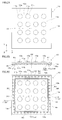
- FIGS. 2A to 2C are a plan view, a side sectional view, and a back view of the first lens array 10 constituting the laminated lens array unit 100.
- the tapered surface 14a is inclined with respect to the Z axis perpendicular to the main surface, and is in a state of approaching the central axis AX on the front side or the object side.
- the tapered surface 14a is disposed in a rectangle or a square along the edge 10r.
- the taper surface 14a and its periphery constitute an enclosing region SR that encloses the group of lens elements 10a from the outside in a plane parallel to the XY plane.
- this surrounding region SR there are a plurality of linear positioning regions R1 and each linear positioning region R1 functions as a positioning portion.
- the surrounding region SR is a rectangular frame-shaped band, and the linear positioning region R1 is arranged closer to the center in each of the four side portions.
- Each linear positioning region R1 extends elongated along the side portion of the surrounding region SR, and has a length that is, for example, about half or less of the side portion of the surrounding region SR. That is, the four linear positioning regions R1 are distributed and arranged at a plurality of locations so as to surround the support portion 10b or the group of lens elements 10a arranged in a matrix.
- a rectangular frame-shaped flat portion 15 is provided outside the boundary portion 14 at the edge portion 10r of the first lens array 10.
- a flat surface 15 a that is a surface of the flat portion 15 on the second lens array 20 side extends along a plane perpendicular to the central axis AX of the multilayer lens array unit 100.
- 3A and 3B are a plan view and a side sectional view of the second lens array 20.
- the boundary portion 24 on the support portion 20b side of the edge portion 20r extends in a square band shape and has a tapered surface 24a.
- the tapered surface 24a is inclined with respect to the Z axis perpendicular to the main surface, and is in a state of approaching the central axis AX on the front side or the object side.
- the tapered surface 24 a of the second lens array 20 extends substantially in parallel to the tapered surface 14 a of the first lens array 10.
- the tapered surface 24a is disposed in a rectangle or a square along the edge 20r.
- the tapered surface 24a and its periphery constitute an enclosing region SR that encloses the group of lens elements 20a from the outside in a plane parallel to the XY plane.
- a plurality of linear positioning regions R2 exist in the surrounding region SR, and each linear positioning region R2 functions as a positioning portion.
- the surrounding region SR is a rectangular frame-shaped band, and the linear positioning region R2 is disposed closer to the center in each of the four side portions.
- Each linear positioning region R2 is elongated along the side portion of the surrounding region SR, and has a length that is, for example, about half or less of the side portion of the surrounding region SR. That is, the four linear positioning regions R2 are distributed and arranged at a plurality of locations so as to surround the support portion 20b or the group of lens elements 20a arranged in a matrix.
- a square frame-shaped flat portion 25 is provided on the edge 20r of the second lens array 20 outside the boundary portion 24.
- a flat surface 25 a that is a surface of the flat portion 25 on the first lens array 10 side extends along a plane perpendicular to the central axis AX of the multilayer lens array unit 100.
- FIG. 4A is a partially enlarged perspective view for explaining the shape and the like of the linear positioning region R1 of the first lens array 10
- FIG. 4B is a portion for explaining the shape and the like of the linear positioning region R2 of the second lens array 20. It is an expansion perspective view.
- a boundary portion 14 exists as a first contact portion.
- a flat and uniform tapered surface 14a is provided on the surface of the boundary portion 14 as described above.
- a low flange 24b is formed as a second contact portion so as to protrude from the flat tapered surface 24a.
- the surface of the flange portion 24b is a convex surface 24c that approximates a cylindrical surface, and its generatrix L extends along the side portion of the surrounding region SR (see FIG. 2C) in the same manner as the tapered surface 24a.
- FIG. 4C in the state where the first lens array 10 of FIG. 2A and the second lens array 20 of FIG. 3A are overlapped and brought into close contact with each other, the positioning region (first positioning portion) R1 of the first lens array 10 Of the tapered surface 14a of the boundary portion (first contact portion) 14 provided on the side and the flange portion (second contact portion) 24b provided on the positioning region (second positioning portion) R2 side of the second lens array 20
- the convex surface 24c approaches or abuts.
- the tapered surface 14a provided on the boundary portion 14 of the first lens array 10 is on the outside, and the convex surface 24c provided on the flange portion 24b of the second lens array 20 is on the inside.
- the tapered surface 14a of the first lens array 10 is disposed outside the convex surface 24c of the second lens array 20.
- the convex surface 24c is in a line contact state in the vicinity of or in contact with the tapered surface 14a at the position of the generatrix L. After this, when it approaches or contacts in a linear region, including the case where it is close but not completely touched, it is called a line hit state.
- the flat surface 25 a perpendicular to the central axis AX of the flat portion 25 provided in the second lens array 20 faces the flat surface 15 a perpendicular to the central axis AX of the flat portion 15 provided in the first lens array 10. And extended in contact with each other.
- the flat surfaces 15a and 25a of the flat portions 15 and 25 of the first and second lens arrays 10 and 20 are in contact with each other and are disposed opposite to each other, so that the first and second lens arrays 10 and 20 are in the Z-axis direction. Are adjusted, and the inclination with respect to the Z-axis is adjusted.
- both lens arrays 10 and 20 are performed with respect to translation (shift) in the Z-axis direction and rotations ⁇ x and ⁇ y about the XY axis. Further, the tapered surfaces 14a provided in the four linear positioning regions R1 of the first lens array 10 and the convex surfaces 24c provided in the four linear positioning regions R2 of the second lens array 20 are close to each other. Alternatively, by abutting, the lateral displacement between the central axes AX of the first and second lens arrays 10 and 20 is prevented, and the relative rotational posture around the central axis AX is adjusted. That is, the lens arrays 10 and 20 are relatively positioned with respect to the translation (shift) in the XY axis direction and the rotation ⁇ z around the Z axis.
- the flat surfaces 15 a and 25 a of the flat portions 15 and 25 of the first and second lens arrays 10 and 20 are made parallel, and more preferably contacted.
- the tapered surface 14a of the first lens array 10 and the convex surface 24c of the flange portion 24b of the second lens array 20 are brought into contact with or close to each other after being brought into close contact with each other.
- first and second lens arrays 10 and 20 are stacked, first, positioning is performed in advance with respect to rotation around the XY axis (more preferably including translation in the Z-axis direction), Next, positioning is performed with respect to translation in the XY-axis direction and rotation around the Z-axis.
- the flat surfaces 15a and 25a of the flat portions 15 and 25 of both lens arrays 10 and 20 are in close contact in principle, but the tapered surface 14a and the convex surface 24c are disposed in close contact. In some cases, they are arranged close to each other.
- the distance between the tapered surface 14a and the convex surface 24c in the X-axis direction or the Y-axis direction is, for example, 1 ⁇ m or more and 10 ⁇ m or less.
- an accuracy of 10 ⁇ m or less is required for positioning between the lens arrays 10 and 20, and therefore, a taper provided in the positioning region (first positioning portion) R1.
- the set value of the distance between the surface 14a and the convex surface 24c provided in the positioning region (second positioning portion) R2 is also 10 ⁇ m or less.
- the design is ensured by ensuring a set value of 1 ⁇ m or more between the taper surface 14a provided in the linear positioning region R1 and the convex surface 24c provided in the linear positioning region R2 in the X-axis direction or the Y-axis direction. An allowable range such as an error is ensured, and assembly that gives priority to the flat surfaces 15a and 25a of the flat portions 15 and 25 coming into contact with the tapered surface 14a and the convex surface 24c becomes relatively easy.
- the positioning between the first and second lens arrays 10 and 20 has been described above, but the positioning between the second and third lens arrays 20 and 30 is also performed by the same method. That is, although not shown in detail, the second and third lens arrays 20 and 30 are also provided with positioning regions corresponding to the positioning portions, respectively, as shown in FIGS. 4A to 4C.
- the tapered surface (first contact portion) provided in the positioning region of the array 20 and the collar portion (second contact portion) provided in the positioning region of the third lens array 30 are close to or in contact with each other. . In other words, by stacking the second and third lens arrays 20 and 30, positioning can be achieved by their own structure.
- the first lens array 10 is formed by injection molding.
- FIG. 5A is a diagram for explaining a mold for molding the first lens array 10.
- the mold apparatus 70 includes a first mold 71 and a second mold 72.
- the first mold 71 and the second mold 72 are mold-matched at the mold-matching surface PL, and a cavity 70 a is formed between the molds 71 and 72.
- a transfer surface 71c for transferring the shape on the first main surface 10p side of the first lens array 10 is formed on the first mold 71 so as to face the cavity 70a.
- a transfer surface 72c for transferring the shape of the first lens array 10 on the second main surface 10q side is formed.
- the transfer surfaces 71c and 72c have a plurality of optical transfer portions 71g and 72g arranged two-dimensionally at a part thereof in order to transfer the optical surfaces 11a and 11b of the lens element 10a.
- the transfer surfaces 71c and 72c have a transfer portion 72r and the like for transferring the tapered surface 14a and the flat surface 15a of the edge portion 10r.
- the mold part 71i forming the transfer surface 71c is integrally formed
- the mold part 72i forming the transfer surface 72c is formed integrally.
- a gate GA communicating with the cavity 70a is formed.
- the gate GA is disposed not on the center of the transfer surfaces 71c and 72c but on the side, and injection molding is performed by a side gate method.
- FIG. 5B is a cross-sectional view illustrating the entire structure of the mold apparatus 70.
- a runner RA is connected to the cavity 70a of FIG. 5A through a gate GA.
- the runner RA is connected to the sprue SP on the resin supply side.
- the molten resin J from the sprue SP obtained by melting the thermoplastic resin fills the runner RA and fills the cavity 70a through the gate GA.
- a molded product 80 including a portion 83 and a lens array body 84 corresponding to the cavity 70a is formed.
- the gate section 83 is subjected to a gate cut process, and the first lens array 10 is obtained by the lens array body 84 at the tip of the gate section 83.
- the first lens array 10 is formed by integral mold portions 71i and 72i, and has no burr on the first main surface 10p side or the second main surface 10q. That is, it becomes easy to arrange the optical surface 11b of the lens element 10a and the tapered surface 14a and the flat surface 15a of the edge 10r relatively accurately.
- the mold element 72 having the transfer surface for transferring the optical surface 11b of the lens element 10a and the tapered surface 14a of the positioning portion can be simultaneously processed by a processing machine.
- the dimensional accuracy between 10a and positioning region (positioning part) R1 can be improved.
- the second and third lens arrays 20 and 30 are also molded by the same method as that for the first lens array 10. That is, the second and third lens arrays 20 and 30 are also manufactured by injection molding a thermoplastic resin by a side gate method. Similarly to the first lens array 10, the second and third lens arrays 20 and 30 can increase the dimensional accuracy between the lens elements 20a and 30a and the positioning portions (for example, the positioning regions R2,). A multilayer lens array unit 100 can be realized.
- FIG. 6 is a diagram illustrating a modification of the positioning unit.
- the convex surface 124c of the flange 24b provided in the second lens array 20 is a flat tapered surface.
- the convex surface 124 c of the second lens array 20 comes into contact with the surface when approaching or contacting the tapered surface 14 a of the first lens array 10.
- Part) 24c has a tapered surface that is in contact with or close to the other, so that relative movement in a specific direction is simplified by contact or proximity with the tapered surface such as the tapered surface 14a. Can be regulated.
- the positioning regions (positioning portions) R1 and R2 include a plurality of locations distributed along the edge portion 10r of the first lens array 10 and the edge portion 20r of the second lens array 20.
- the first lens array 10 and the second lens array 20 are moved along the edges of the first lens array 10 and the second lens array 20 by the relative movement restriction using the tapered surface 14a and the convex surface 24c. Space-saving and precise positioning can be achieved with respect to translation and rotation.
- the positioning regions (positioning portions) R1 and R2 between the lens elements 10a. If the positioning regions (positioning portions) R1 and R2 are provided between the lens elements 10a, that is, in the peripheral portions 10c, 20c, and 30c, the positioning convex side becomes thick and the positioning concave side becomes thin. For this reason, when molding by injection molding, the resin is less likely to flow through the thin-walled portion, the molding resin pressure is less likely to be applied to the lens element 10a, resulting in transfer failure, and the flow of the resin is disturbed, resulting in welds. To do. On the other hand, when the positioning portion is provided outside the lens element 10a, that is, at the edge portions 10r, 20r, and 30r, only the outer portion is thinned, so that transfer defects and weld problems are less likely to occur.
- the first lens array 10 is placed on the second lens array 20 with rough alignment.
- the smooth combination and precise positioning of the first lens array 10 and the second lens array 20 are possible.
- the positioning portion including the tapered surface 14a, the convex surface 24c, and the like is disposed on the edge side or the outer peripheral side of the first and second lens arrays 10, 20, the function of the optical surface of the lens elements 10a, 20a, 30a. Can be prevented, and a design in which substantially the entire surface of the sensor array 60 of the image pickup apparatus 1000 is used as an image plane is also possible, which makes it easy to achieve high image quality.
- the diaphragm plates 41 to 43 are provided at positions between the lens elements 10a as a countermeasure against crosstalk.
- the positioning regions (positioning portions) R1 and R2 are arranged outside the lens element 10a or the support portion 10b. Since they are provided, it is easy to avoid interference between them. That is, if the positioning regions (positioning portions) R1 and R2 are provided between the lens elements 10a, they are likely to interfere with the diaphragm plates 41 to 43 and the like, and it becomes difficult to dispose the diaphragm plates 41 to 43, thereby increasing crosstalk. there is a possibility.
- the positioning structure between the first and second lens arrays 10 and 20 can be switched up and down. That is, the tapered surface 14a of the boundary portion (first contact portion) 14 provided on the positioning region (first positioning portion) R1 side of the first lens array 10 is similar to the convex surface 24c of the flange portion 24b shown in FIG. 4B. Can be aligned or positioned by bringing the convex surface on the first lens array 10 side and the tapered surface 24a of the second lens array 20 close to or in contact with each other.
- the flat surface 15 a provided on the flat portion 15 of the first lens array 10 and the flat surface 25 a provided on the flat portion 25 of the second lens array 20 do not necessarily need to extend over the entire flat portions 15 and 25. However, it is only necessary to extend so as to be able to contact each other only at a plurality of positions that enable positioning during stacking.
- the laminated lens array unit and the like according to the second embodiment will be described.
- the laminated lens array unit of the second embodiment is a modification of the laminated lens array unit of the first embodiment, and items that are not particularly described are the same as those of the first embodiment.
- a plurality of point-like positioning regions R22 exist in the surrounding region SR of the second lens array 20, and each point-like positioning region R22 functions as a positioning unit.
- the dot positioning regions R22 are arranged at two locations in each of the four side portions constituting the surrounding region SR. That is, eight point-like positioning regions R22 are arranged in a separated state so as to be distributed along the surrounding region SR.
- a low and short protrusion 124b is formed in the point-like positioning region R22 so as to protrude from the flat tapered surface 24a as the second contact portion.
- the protrusion 124b has a dome-like outer shape close to a cylinder like a halves or rugby balls, and the surface of the protrusion 124b is a convex surface 124c close to a hemisphere or a cylinder. Strictly speaking, when the convex surface 124c approaches or comes into contact with the tapered surface 14a of the first lens array 10, the convex surface 124c is in a point hit state from the standpoint of effectiveness in positioning. In addition, after this, when it approaches or contacts in a dotted line-like or short linear area including the case where it is close but not completely touched, it will be referred to as a spotted state.
- both the lens arrays 10 and 20 are formed by the tapered surface 14a of the boundary portion (first contact portion) 14 and the convex surface (second contact portion) 124c of the projection portion (second contact portion) 124b. It is possible to precisely position in a space-saving manner with respect to translation and rotation in the XY plane along these edges.
- the dot positioning region R22 can be thinned out to the minimum necessary. Specifically, as shown in FIG. 8, in one side portion SR1, among the four side portions constituting the surrounding region SR extending along the boundary portion 24 of the second lens array 20, dots are formed in two places. The positioning region R22 is arranged, and in the remaining three side portions SR2, the dot-like positioning region R22 is arranged at one place. In this case, translation in the XY plane is restricted by all side portions SR1 and SR2, and rotation in the XY plane is restricted by the side portion SR1 alone.
- the laminated lens array unit according to the third embodiment will be described below.
- the laminated lens array unit of the third embodiment is a modified example of the laminated lens array unit of the first and second embodiments, and items not specifically described are the same as those of the first embodiment. .
- the linear positioning region R2 is arranged at one location, and in the remaining three side portions SR2, one location is provided.
- a point-shaped positioning region R22 is arranged in the area. In this case, translation in the XY plane is restricted by all side portions SR1 and SR2, and rotation in the XY plane is restricted by the side portion SR1 alone.
- the laminated lens array unit of the fourth embodiment is a modification of the laminated lens array unit of the first embodiment, and items that are not particularly described are the same as those of the first embodiment.
- each linear positioning region R13 functions as a positioning unit. Specifically, the linear positioning region R13 is disposed in each of the four corner portions constituting the surrounding region SR. In each linear positioning region R13, a boundary portion 14 is formed as a first contact portion, and a tapered surface 14a is formed as a flat surface.
- a plurality of linear positioning regions R23 exist in the surrounding region SR of the second lens array 20, and each linear positioning region R23 functions as a positioning unit. Specifically, the linear positioning region R23 is arranged in each of the four corner portions constituting the surrounding region SR. Each linear positioning region R23 is formed with a low and long protruding portion 224b as a second contact portion so as to protrude from the flat tapered surface 24a.
- the tapered surface 14a of the boundary portion (first contact portion) 14 on the first lens array 10 side and the protrusion on the second lens array 20 side when the first and second lens arrays 10 and 20 are stacked, the tapered surface 14a of the boundary portion (first contact portion) 14 on the first lens array 10 side and the protrusion on the second lens array 20 side.
- the convex surface 224c of the portion (second contact portion) 224b approaches or comes into contact, automatic positioning by line hit is performed. That is, the tapered surface (first contact portion) 14a and the convex surface (second contact portion) 224c save both the lens arrays 10 and 20 with respect to translation and rotation in the XY plane along their edges. Can be positioned precisely.
- the laminated lens array unit according to the fifth embodiment will be described below.
- the laminated lens array unit of the fifth embodiment is a modification of the laminated lens array unit of the first embodiment, and items not specifically described are the same as those of the first embodiment.
- linear positioning regions R23 at one location and dotted positioning regions R24 at multiple locations, each functioning as a positioning unit.
- the linear positioning region R23 is disposed in one corner portion SR3 among the four corner portions constituting the surrounding region SR, and the dotted positioning region R24 is disposed in the remaining three corner portions SR4.
- a low and long protruding portion 224b is formed as a second contact portion so as to protrude from the flat tapered surface 24a.
- a low and short protrusion 124b is formed as a second contact portion so as to protrude from the flat tapered surface 24a.
- the taper surface (first abutting portion) 14a and the convex surface (second abutting portion) 224c are automatically positioned by line contact, and the tapered surface (first abutting portion) 14a and the convex surface (convex surface) are convex. Automatic positioning by point hitting is performed by the surface (second contact portion) 124c.
- the long protrusion 224b is provided at one of the four corners constituting the surrounding region SR.
- the long protrusion 224b can be provided at two or three of the four corners. .
- FIG. 12 shows an example in which a part of the first lens array 10 shown in FIG. 11 is changed.
- a set of two point positioning regions R25 is arranged in place of one linear positioning region R23 at or near one corner portion SR3. With these two point-like positioning regions R25, both lens arrays 10 and 20 can be positioned with respect to rotation in the XY plane along their edges.
- FIG. 13 shows another example in which a part of the first lens array 10 shown in FIG. 11 is changed.
- only two adjacent corner portions SR4 are utilized, and one side portion SR1 (fourth) different from the three side portions SR1 (first to third side portions) constituting the two corner portions SR4.
- one linear positioning region R2 is arranged in the side portion SR1r.
- the two lens arrays 10 and 20 can be positioned with respect to translation and rotation in the XY plane along these edges by the two point-like positioning regions R24 and the one linear positioning region R2.
- Two adjacent corner portions SR4 may be per line or per plurality of points, and one side portion SR1 (fourth side portion SR1r) may be per point.
- FIG. 14 is another example in which a part of the first lens array 10 shown in FIG. 11 is changed.
- two point-like positioning regions R24 are arranged in the two corner portions SR4, and a positioning portion composed of a pair of point-like positioning regions R25 is arranged in the two corner portions SR3 or in the vicinity thereof.
- Positioning relating to rotation in the XY plane is mainly achieved by the pair of point-like positioning regions R25.
- FIG. 15 shows another example in which a part of the first lens array 10 shown in FIG. 11 is changed.
- one point-like positioning region R24 is arranged in one corner portion SR4, and two side portions SR1 (first and second side portions) different from the two side portions SR1 (first and second side portions) adjacent to the corner portion SR4 ( Among the third and fourth side portions), one linear positioning region R2 is disposed on one side, and one point positioning region R22 is disposed on the other side.
- both the lens arrays 10 and 20 can be positioned with respect to translation and rotation in the XY plane along these edges by one linear positioning region R2 and one point positioning region R24.
- a point-like positioning region R22 may be provided in each of the third and fourth side portions.
- the laminated lens array unit of the sixth embodiment is a modification of the laminated lens array unit of the first embodiment, and items that are not particularly described are the same as those of the first embodiment.
- a linear positioning region R26 exists over the entire circumference corresponding to the boundary portion 24 in the rectangular surrounding region SR of the second lens array 20, and this functions as a positioning portion. . That is, the tapered surface 24a of the boundary portion 24 functions as the second contact portion as it is.
- Automatic positioning is performed by the proximity or contact of the tapered surface 24a of the boundary portion (second contact portion) 24 on the second lens array 20 side as shown in FIG. 16A or the like. That is, both the lens arrays 10 and 20 can be accurately positioned in a space-saving manner with respect to translation and rotation in the XY plane along these edges by the both tapered surfaces 14a and 24a.
- the tapered surfaces 14a and 24a do not need to extend continuously, and the tapered surfaces 14a and 24a are intermittently in contact with each other by providing shallow depressions or the like at appropriate positions of the tapered surfaces 14a and 24a. Or it can be close.
- the laminated lens array unit according to the seventh embodiment will be described below.
- the laminated lens array unit of the seventh embodiment is a modification of the laminated lens array unit of the second embodiment, and items not specifically described are the same as those of the second embodiment.
- the edge portion 20r is provided with a tapered portion 20t having a slightly tapered surface so as to become narrower toward the main surface on the image side.
- a protrusion 26 having a semicircular vertical reference surface 26a with the image side parallel to the central axis AX as a bottom is provided on a part of the tapered portion 20t.
- the vertical reference surface 26a is formed simultaneously with the molding of the lens array 20 by a molding surface accurately formed on the mold so as to be parallel to the central axis AX.
- the vertical reference surface 26a for example, when the optical performance of the lens array 20 is measured by an inspection machine, the vertical reference surface 26a is brought into contact with a jig or the like of the inspection machine to The reference surface 26a can be used for positioning the lens array 20 with respect to the inspection machine, and measurement can be performed smoothly.
- a plurality of vertical reference surfaces 26a are provided on each side of the edge 20r.
- the lens array 10 can also be provided with a similar reference surface at the edge 10r.
- the shape of the vertical reference planes provided at the edges 10r and 20r is not limited to a semicircular shape, and may be an elliptical shape or a polygonal shape such as a trapezoidal shape or a triangular shape.
- the diameter be reduced in accordance with the taper or inclination of the taper as in the present embodiment.
- the inclination of the tapered portion 20t is not limited to be narrow on the image side, but can be narrow on the object side.
- a taper may be provided at the edge and a vertical reference plane may be provided.
- the laminated lens array unit and the like according to the embodiment have been described above, but the laminated lens array unit and the like according to the present invention are not limited to the above examples.
- the arrangement of the lens elements 10a, 20a, 30a constituting the lens arrays 10, 20, 30 and the shape of the optical surfaces 11a, 11b,... are used or the specifications of the stacked lens array unit 100 or the imaging device 1000. It can be changed as appropriate according to the situation.
- the lens elements 10a, 20a, and 30a are not limited to being arranged at 4 ⁇ 4 lattice points, but can be arranged at lattice points of 3 ⁇ 3, 5 ⁇ 5, and the like.
- the lens array constituting the laminated lens array unit 100 is not limited to the above-described three layers (lens arrays 10, 20, 30), but may be two layers (only the lens arrays 10, 20) or four layers or more. Can do.
- the tapered surfaces 14a and 24a do not have to be completely flat, and can be tapered surfaces having a slight concave or convex curvature.
- the outline shape of the laminated lens array unit 100 or the lens arrays 10, 20, and 30 and the shape of the surrounding region are generally rectangular or square, that is, a quadrangle, but can be slightly modified.
- a lens array having an outline of an octagon or the like close to a quadrangle with a corner dropped (which is also included in a substantially quadrangular outline) is also an element constituting the multilayer lens array unit according to the present invention. it can.
- the number of the flanges 24b and the protrusions 124b and 224b described above can be added in the surplus space, but the processing accuracy is required to reduce the number of the flanges 24b and the protrusions 124b and 224b. This is advantageous from the viewpoint of reducing component costs.
Landscapes
- Physics & Mathematics (AREA)
- General Physics & Mathematics (AREA)
- Optics & Photonics (AREA)
- Lens Barrels (AREA)
- Transforming Light Signals Into Electric Signals (AREA)
- Studio Devices (AREA)
Abstract
高い組立精度を実現でき、高精度の成形が可能な積層型レンズアレイユニット及びこれを組み込んだ撮像装置を提供する。第1レンズアレイ10側のテーパー面(第1当接部)14aと第2レンズアレイ20側の凸状面(第2当接部)24cとの少なくとも一方が、他方に対して当接又は近接するテーパー状面を有するので、特定方向への相対的な移動を簡易に規制することができる。さらに、上記積層型レンズアレイユニット100では、位置決め領域(位置決め部)R1,R2が第1レンズアレイ10の縁部10rと第2レンズアレイ20の縁部20rとに沿って分布する複数箇所を含む包囲領域SRに設けられるので、第1レンズアレイ10と第2レンズアレイ20とをこれらの縁に沿ったXY面内の並進や回転に関して省スペースで精密に位置決めすることができる。
Description
本発明は、2次元的に配列された複数のレンズを含むレンズアレイを積み重ねた複眼光学系用の積層型レンズアレイユニット、及びレンズアレイユニットを組み込んだ撮像装置に関する。
近年の撮像光学系に対する薄型化の要求は非常に高まっている。それに対応するために、光学設計による全長短縮やそれに伴う誤差感度増大に対応した製造精度向上を行ってきたが、さらなる薄型化の要求に対応するためには、従来の1つの光学系と撮像素子とによって像を得るという手法では不十分となっている。
そこで、撮像素子の領域を分割して、それぞれに光学系を配置し、得られた画像を処理することで、最終的な画像出力を行う複眼光学系と呼ばれる光学系が、薄型化への要求に対応するために注目されている。現在までに、各種の複眼光学系が提案されているが、薄型化しつつ高画質を得るためにレンズ間で高精度なアライメントを実現可能にする技術を提案しているものはなかった。
画像読取等に用いられる公知のレンズアレイ又はその組立品として、1次元に配列された複数のレンズとこれらのレンズをつなぐホルダー部とを樹脂で一体成形し、ホルダー部に設けた凹部及び凸部により2つのレンズアレイを嵌合させるものがある(特許文献1参照)。特許文献1の場合、各レンズアレイは、射出成形によって作製される。具体的には、レンズアレイの側面にゲートを設け、ゲートから溶融した樹脂を注入する。そして、レンズ用樹脂材料を冷却固化した後、金型から取り出すことで、レンズアレイを製造している。
また、撮像装置に用いられる公知のレンズとして、複数のレンズアレイを構成要素のレンズ間に設けられた位置決め部により位置決めしつつ接合し、接合後に個片に切断して複合レンズを得るものがある(特許文献2参照)。特許文献2の場合、第1レンズアレイに設けられた凸部と、第2レンズアレイに設けられた凹部とを用いて両レンズアレイを嵌合させる。この際、対向する光学面間に形成された空隙を囲んで密閉するように各光学面の周囲が接合され、最終的に、レンズ間を切断して撮像レンズに個片化している。
しかしながら、上記特許文献1には、レンズアレイの嵌合に用いる凹凸部として、円柱状の凸部とこれと同一形状の円筒状の窪みからなる凹部との組み合わせや、直方体状の凸部とこれと同一形状の窪みからなる凹部との組合せが図示されているだけであり、実際の組み立てを想定したときの位置決め精度の確保について十分考慮がされていない。このため、特許文献1の手法は、例えば10μm以下の組立精度が求められる本願のような撮像用途に適しない。また、上記特許文献1に開示された製造方法では、光軸に垂直な平面方向の位置決め精度を高くしようとすると、嵌合が不十分になりやすく、これが原因でレンズアレイ積層体の厚みの変動幅が大きくなったり、嵌合により歪みが生じてレンズアレイの光学性能に悪影響が生じたり、場合によっては、嵌合の過程でレンズアレイが破損したりするおそれがある。さらに、光学系の薄型化に伴ってレンズアレイの厚みを薄くすると、垂直な壁面を持つ凹凸の存在により、樹脂の流動性が悪くなってレンズアレイの型空間内全体に樹脂を十分に充填できない可能性がある。また、樹脂を充填できたとしても、ゲートから遠い位置にあるレンズでは、圧力がかからずレンズ面の精度が低下する可能性がある。また、レンズアレイを射出成形で作製した場合、凹凸部が離型しづらくなるという問題もある。
特許文献2においても、一方のレンズアレイに形成された突起や他方のレンズアレイに形成された凹部として、垂直な壁面を備えたものしか記載されておらず、実際にレンズアレイ積層体を組み立てる場合に生じる問題が十分考慮されていない。すなわち、凹凸の嵌合によって位置決めの精度を高くしようとすると、嵌合時にレンズアレイにストレスがかかり、特許文献1について述べたのと同様の様々な問題を生じるおそれがある。また、特許文献2には、例えばゲート位置等の成形方法に関する言及がなく、樹脂の流動性その他の成形条件に関して特段の考慮がされていない。
本発明は、上記背景技術に鑑みてなされたものであり、高い光学性能を確保しつつ、高い精度で組立てられ、しかも、高精度の成形が可能な積層型レンズアレイユニット及びこれを組み込んだ撮像装置を提供することを目的とする。
上記課題を解決するため、本発明に係る積層型レンズアレイユニットは、それぞれ、光軸方向から見て四角形(より具体的には、正方形を含む矩形)の輪郭を有し、2次元的に配列された複数のレンズ要素を有する第1レンズアレイ及び第2レンズアレイと、第1レンズアレイの縁部と第2レンズアレイの縁部とに沿って複数のレンズ要素を囲む包囲領域に設けられた位置決め部とを備え、上記位置決め部は、第1レンズアレイ側に配置される第1当接部と、第2レンズアレイ側に配置され第1当接部に対向する第2当接部とを有しており、第1及び第2レンズアレイの縁部に対応する四角形枠に平行な平面に沿った位置と当該平面に垂直な軸のまわりの回転とに関して、第1及び第2レンズアレイの相対的移動を規制し、上記包囲領域より内側では、第1レンズアレイと第2レンズアレイとが互いに離れており、上記第1及び第2当接部の少なくとも一方は、他方に対して当接又は近接するテーパー状面を有する。ここで、位置決め部は、包囲領域に沿った連続的なものに限らず、離散的な部分又は領域の集合とできる。
上記積層型レンズアレイユニットでは、第1レンズアレイ側の第1当接部と第2レンズアレイ側の第2当接部との少なくとも一方が、他方に対して当接又は近接するテーパー状面を有しており、包囲領域より内側では、第1レンズアレイと第2レンズアレイとは互いに離れた構成を有する。そして、第1及び第2当接部を当接又は近接させることにより、四角形枠に平行な平面に沿った位置と当該平面に垂直な軸のまわりの回転とに関して、第1及び第2レンズアレイの相対的移動を規制する。これにより、レンズアレイにストレスをかけることなく、レンズアレイにとって必要な平面方向及び平面に垂直な軸まわりの回転方向の規制を行うことができる。従って、光学性能を高く保ちつつ、高い精度で組立を行うことができる。また、レンズアレイの隣り合うレンズ要素の間の構造をシンプルにすることができるので、成形を高精度に行うことができ、レンズ要素の有効領域を広く確保しやすくなる。
本発明の具体的な側面又は態様では、位置決め部は、四角形枠の4つの辺部分を構成する各辺部分において少なくとも1箇所以上に設けられている。
本発明の別の側面では、位置決め部は、各辺部分において、1箇所以上の線当たり又は複数箇所の点当たり状態となることによって位置決めを行う。
本発明のさらに別の側面では、位置決め部は、四角形枠の4つの角部分を構成する各角部分に設けられている。
本発明のさらに別の側面では、位置決め部は、少なくとも1つの角部分について、線当たり又は複数箇所の点当たり状態で位置決めを行う。
本発明のさらに別の側面では、位置決め部は、四角形枠の4つの角部分のうち隣り合う2つの角部分と、当該2つの角部分を構成する四角形枠の第1、第2及び第3の辺部分とは異なる第4の辺部分とに設けられており、上記2つの角部分及び第4の辺部分の位置決め部のうち少なくとも1つが、線当たり又は複数箇所の点当たり状態で位置決めを行う。
本発明のさらに別の側面では、位置決め部は、四角形枠の4つの角部分のうち1つの角部分と、当該角部分を構成する四角形枠の第1及び第2の辺部分とは異なる第3及び第4の辺部分のそれぞれとに設けられており、上記1つの角部分、第3の辺部分、及び第4の辺部分のうち少なくとも1つが、線当たり又は複数箇所の点当たり状態で位置決めを行う。
本発明のさらに別の側面では、第1及び第2レンズアレイは、光学材料で形成された一体物からなる。レンズアレイを光学材料からなる一体物とすることにより、屈折や反射を生じる界面を少なくすることができ、光学性能の向上に有利である。
本発明のさらに別の側面では、第1当接部と第2当接部との隙間は、10μm以下である。この場合、高画質化に有利となり、例えば、超解像処理によって100万画素以上の画像を得ることができる。
本発明のさらに別の側面では、第1当接部と第2当接部とは、互いに対向する一対の平坦なテーパー面をそれぞれ有する。この場合、テーパー面同士を対向させるため組立が簡単になり、位置決めの確実性が増す。
本発明のさらに別の側面では、第1当接部と第2当接部とは、互いに対向する平坦なテーパー面と凸状面とをそれぞれ有する。この場合、近接又は接触する面積が小さくなるので、精度良く位置決め部を形成しやすくなる。
本発明のさらに別の側面では、第1及び第2レンズアレイの少なくとも一方は、光軸方向に対して垂直な平坦面を有する平坦部を有し、第1及び第2レンズアレイは、平坦部において当接している。レンズアレイ同士を平面部で接触させるだけで光軸方向等に関して位置決めでき、位置決め精度をより高く保ちつつ、組立を簡単にすることができる。
上記課題を解決するため、本発明に係る撮像装置は、上述の積層型レンズアレイユニットと、積層型レンズアレイユニットを構成する複数のレンズアレイに対応して設けられたセンサーアレイと、センサーアレイによって検出された画像信号に対して処理を行う画像処理部とを備える。
上記撮像装置では、上述した積層型レンズアレイユニットを用いるので、薄型で高精度の合成レンズを配列した積層型レンズアレイユニットを備える複眼光学系によって薄型ながら高精度の撮影が可能になる。
〔第1実施形態〕
図1A及び1Bに示すように、本実施形態の積層型レンズアレイユニット100は、撮像装置1000に組み込まれる。
図示の積層型レンズアレイユニット100は、複数(具体的には3つ)のレンズアレイ10,20,30を積み重ねた積層体であり、複眼光学系として用いられる。これらの第1、第2、及び第3レンズアレイ10,20,30は、XY面に平行に延びる四角平板状の部材であり、XY面に垂直なZ軸方向に積み重ねられて相互に接合されている。
図1A及び1Bに示すように、本実施形態の積層型レンズアレイユニット100は、撮像装置1000に組み込まれる。
図示の積層型レンズアレイユニット100は、複数(具体的には3つ)のレンズアレイ10,20,30を積み重ねた積層体であり、複眼光学系として用いられる。これらの第1、第2、及び第3レンズアレイ10,20,30は、XY面に平行に延びる四角平板状の部材であり、XY面に垂直なZ軸方向に積み重ねられて相互に接合されている。
なお、撮像装置1000は、上述した積層型レンズアレイユニット100の他に、積層型レンズアレイユニット100を構成する個々の合成レンズ1aに対応して設けられた複数の検出部(センサー要素)61を有するセンサーアレイ60と、センサーアレイ60によって検出された画像信号に対して視野分割方式又は超解像方式に適合する画像処理を行う画像処理部65とを備える。積層型レンズアレイユニット100は、センサーアレイ60に接合され、矩形枠状のケース50に収納されている。センサーアレイ60は、複数のチップを並べたものでもよいし、1枚のチップを領域分割したものでもよい。ここで、視野分割方式とは、個々のレンズによって結像された異なる視野の画像を、画像処理によって各視野の画像をつなぎ合わせることで1つの画像を得る方式を指す。また、超解像方式とは、個々のレンズによって結像された同じ視野の画像から画像処理によって1つの高解像度の画像を得る方式を指す。
積層型レンズアレイユニット100において、物体側の第1レンズアレイ10は、光学材料である光透過性の熱可塑性樹脂製の一体成形品、換言すれば、熱可塑性樹脂からなる一体物であり、中心軸AX方向又はZ軸方向から見て略正方形の輪郭を有する。第1レンズアレイ10は、それぞれが光学素子である複数のレンズ要素10aと、複数のレンズ要素10aを周囲から支持する支持部10bと、支持部10bの外側に帯状に延在する四角枠状の縁部10rとを有する。第1レンズアレイ10を構成する複数のレンズ要素10aは、XY面に平行に配列された正方の格子点(図示の例では4×4の16点)上に2次元的に配置されている。各レンズ要素10aは、物体側の第1主面10pにおいて凸の第1光学面11aを有し、像側の第2主面10qにおいて凸の第2光学面11bを有する。両光学面11a,11bは、例えば非球面となっている。支持部10bは、平板状の部分であり、各レンズ要素10aの周りをそれぞれ囲むように複数の周囲部分10cを備える。支持部10bの横方向の周辺又は外側にある四角枠状の縁部10rは、第1レンズアレイ10を第2レンズアレイ20と接合するための部分となっている。
図1Bに示す中間の第2レンズアレイ20は、熱可塑性樹脂製の一体成形品であり、中心軸AX方向から見て略正方形の輪郭を有する。第2レンズアレイ20は、それぞれが光学素子である複数のレンズ要素20aと、複数のレンズ要素20aを周囲から支持する支持部20bと、支持部20bの外側に帯状に延在する四角枠状の縁部20rとを有する。複数のレンズ要素20aは、XY面に平行に配列された正方の格子点(図示の例では4×4の16点)上に2次元的に配置されている。各レンズ要素20aは、物体側の第1主面20pにおいて凹の第1光学面21aを有し、像側の第2主面20qにおいて凸の第2光学面21bを有する。両光学面21a,21bは、例えば非球面となっている。支持部20bは、平板状の部分であり、各レンズ要素20aの周りをそれぞれ囲むように複数の周囲部分20cを備える。支持部20bの横方向の周辺又は外側にある四角枠状の縁部20rは、第2レンズアレイ20を第1及び第3レンズアレイ10,30と接合するための部分となっている。
像側の第3レンズアレイ30は、熱可塑性樹脂製の一体成形品であり、中心軸AX方向から見て略正方形の輪郭を有する。第3レンズアレイ30は、それぞれが光学素子である複数のレンズ要素30aと、複数のレンズ要素30aを周囲から支持する支持部30bと、支持部30bの外側に帯状に延在する四角枠状の縁部30rとを有する。複数のレンズ要素30aは、XY面に平行に配列された正方の格子点(図示の例では4×4の16点)上に2次元的に配置されている。各レンズ要素30aは、物体側の第1主面30pにおいて凹の第1光学面31aを有し、像側の第2主面30qにおいて凸の第2光学面31bを有する。両光学面31a,31bは、例えば非球面となっている。支持部30bは、平板状の部分であり、各レンズ要素30aの周りをそれぞれ囲むように複数の周囲部分30cを備える。支持部30bの横方向の周辺又は外側にある四角枠状の縁部30rは、第3レンズアレイ30を第2レンズアレイ20と接合するための部分となっている。
以上のレンズアレイ10,20,30は、機械や手作業によって順次積み重ねることによって、自身の構造及び自重で互いに位置決めされる。つまり、セルフアライメントされる。また、レンズアレイ10,20,30は、積み重ねる際に縁部10r,20r,30r間に例えば光硬化性樹脂を供給し積み重ねた後に光硬化性樹脂を硬化させることによって、互いに接合又は接着される。このような接合又は接着によって、2次元的にマトリックス状に配列された多数の合成レンズ1aを備える積層型レンズアレイユニット100が得られる。各合成レンズ1aの光軸OAは、全体の中心軸AXに平行になっている。ここで、実際にレンズアレイ10,20,30を製造する場合、形状誤差や位置誤差を完全になくすことはできないため、セルフアライメントによって、後述する全ての位置決め領域が当接する場合もあるし、一部のみが当接し残りは近接する場合もあるし、全て近接する場合もあり得る。いずれの場合であっても、レンズアレイ10,20,30の形状が許容可能な一定範囲のバラツキに収まっていれば、セルフアライメントによって、例えば第1レンズアレイ10と第2レンズアレイ20とを公差内に位置決めすることができる。
なお、第1レンズアレイ10と第2レンズアレイ20との間には、一対の支持部10b,20bに挟持されて固定された薄い遮光性の第1絞り板41が配置されている。この第1絞り板41には、詳細な説明を省略するが、各レンズ要素10aに対応して多数の開口が形成されている。第2レンズアレイ20と第3レンズアレイ30との間には、一対の支持部20b,30bに挟持されて固定された薄い遮光性の第2絞り板42が配置されている。この第2絞り板42には、詳細な説明を省略するが、各レンズ要素20a等に対応して多数の開口が形成されている。第3レンズアレイ30の像側には、接着等によって支持部30bに固定された薄い遮光性の第3絞り板43が配置されている。この第3絞り板43には、詳細な説明を省略するが、各レンズ要素30a等に対応して多数の開口が形成されている。
積層型レンズアレイユニット100を収納するケース50の物体側にも、ケース50への接着等によって固定された入射絞り板45が配置されている。ケース50や入射絞り板45には、詳細な説明を省略するが、各レンズ要素10a等に対応して多数の開口が形成されている。
図2A~2Cは、積層型レンズアレイユニット100を構成する第1レンズアレイ10の平面図、側方断面図、及び裏面図である。第1レンズアレイ10の裏面側において、縁部10rのうち支持部10b側の境界部14は、四角帯状に延在しており、テーパー面14aを有している。テーパー面14aは、主面に垂直なZ軸に対して傾斜しており、表側又は物体側で中心軸AXに近づくような状態となっている。テーパー面14aは、縁部10rに沿って矩形又は四角に配置されている。、テーパー面14a及びその周辺は、XY面に平行な面内で考えて、一群のレンズ要素10aを外側から囲む包囲領域SRとなっている。この包囲領域SR内には、複数箇所に線状位置決め領域R1が存在し、各線状位置決め領域R1が位置決め部として機能する。具体的には、包囲領域SRは、四角枠状の帯域であり、4つの辺部分の各々において中央寄りに線状位置決め領域R1が配置されている。各線状位置決め領域R1は、包囲領域SRの辺部分に沿って細長く延び、包囲領域SRの辺部分の例えば半分程度以下の長さを有する。つまり、4つの線状位置決め領域R1は、支持部10b又はマトリクス状に配列された一群のレンズ要素10aを囲むように複数箇所に分布して配置されている。
第1レンズアレイ10の縁部10rには、境界部14の外側において、四角枠状の平坦部15が設けられている。平坦部15の第2レンズアレイ20側の表面である平坦面15aは、積層型レンズアレイユニット100の中心軸AXに垂直な平面に沿って延びている。
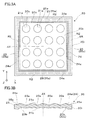
図3A及び3Bは、第2レンズアレイ20の平面図及び側方断面図である。第2レンズアレイ20の表面側において、縁部20rのうち支持部20b側の境界部24は、四角帯状に延在しており、テーパー面24aを有している。テーパー面24aは、主面に垂直なZ軸に対して傾斜しており、表側又は物体側で中心軸AXに近づくような状態となっている。組立後において、第2レンズアレイ20のテーパー面24aは、第1レンズアレイ10のテーパー面14aに対向して略平行に延びる。テーパー面24aは、縁部20rに沿って矩形又は四角に配置されている。テーパー面24a及びその周辺は、XY面に平行な面内で考えて、一群のレンズ要素20aを外側から囲む包囲領域SRとなっている。この包囲領域SR内には、複数箇所の線状位置決め領域R2が存在し、各線状位置決め領域R2が位置決め部として機能する。具体的には、包囲領域SRは、四角枠状の帯域であり、4つの辺部分の各々において中央寄りに線状位置決め領域R2が配置されている。各線状位置決め領域R2は、包囲領域SRの辺部分に沿って細長く延び、包囲領域SRの辺部分の例えば半分程度以下の長さを有する。つまり、4つの線状位置決め領域R2は、支持部20b又はマトリクス状に配列された一群のレンズ要素20aを囲むように複数箇所に分布して配置されている。
第2レンズアレイ20の縁部20rには、境界部24の外側において、四角枠状の平坦部25が設けられている。平坦部25の第1レンズアレイ10側の表面である平坦面25aは、積層型レンズアレイユニット100の中心軸AXに垂直な平面に沿って延びている。
図4Aは、第1レンズアレイ10の線状位置決め領域R1の形状等を説明する部分拡大斜視図であり、図4Bは、第2レンズアレイ20の線状位置決め領域R2の形状等を説明する部分拡大斜視図である。図4Aに示す第1レンズアレイ10の線状位置決め領域R1には、第1当接部として境界部14が存在する。境界部14の表面には、上述のように平坦で一様なテーパー面14aが設けられている。一方、図4Bに示す第2レンズアレイ20の線状位置決め領域R2には、第2当接部として平坦なテーパー面24aから突出するように低い畝部24bが形成されている。畝部24bの表面は、円筒面に近似する凸状面24cとなっており、その母線Lは、テーパー面24aと同様に包囲領域SR(図2C参照)の辺部分に沿って延びている。図4Cに示すように、図2Aの第1レンズアレイ10と図3Aの第2レンズアレイ20とを重ね合わせて密着させた状態では、第1レンズアレイ10の位置決め領域(第1位置決め部)R1側に設けた境界部(第1当接部)14のテーパー面14aと、第2レンズアレイ20の位置決め領域(第2位置決め部)R2側に設けた畝部(第2当接部)24bの凸状面24cとが近接又は当接する。つまり、第1レンズアレイ10の境界部14に設けたテーパー面14aは外側にあり、第2レンズアレイ20の畝部24bに設けた凸状面24cは内側にある。中心軸AXの方向から見た場合、第2レンズアレイ20の凸状面24cを囲む外側に第1レンズアレイ10のテーパー面14aが配置される。この際、凸状面24cは、母線Lの位置でテーパー面14aに近接又は接触する線当たり状態となる。これ以降において、近接するが完全に接触しない場合も含めて、線状の領域で近接又は接触する場合は線当たり状態と呼ぶものとする。さらに、第2レンズアレイ20に設けられた平坦部25の中心軸AXに垂直な平坦面25aは、第1レンズアレイ10に設けられた平坦部15の中心軸AXに垂直な平坦面15aに対向して当接した状態で延びている。このように第1及び第2レンズアレイ10,20の平坦部15,25の平坦面15a,25aが当接して対向配置されることで、第1及び第2レンズアレイ10,20のZ軸方向の間隔が調整され、Z軸に対する傾きが調整される。つまり、Z軸方向の並進(シフト)と、XY軸のまわりの回転θx,θyとに関して両レンズアレイ10,20の相対的な位置決めがなされる。また、第1レンズアレイ10の4つの線状位置決め領域R1に設けられているテーパー面14aと、第2レンズアレイ20の4つの線状位置決め領域R2に設けられている凸状面24cとが近接又は当接することで、第1及び第2レンズアレイ10,20の中心軸AX相互の横方向の位置ずれが防止され、中心軸AXのまわりの相対的回転姿勢が調整される。つまり、XY軸方向の並進(シフト)と、Z軸のまわりの回転θzとに関して両レンズアレイ10,20の相対的な位置決めがなされる。
ここで、第1及び第2レンズアレイ10,20の積み重ねに際して、まず、第1及び第2レンズアレイ10,20の平坦部15,25の平坦面15a,25aを平行にし、より好ましくは当接又は密着させてから、第1レンズアレイ10のテーパー面14aと第2レンズアレイ20の畝部24bの凸状面24cとを当接又は近接させるようにすることが好ましい。このようにすると、第1及び第2レンズアレイ10,20を積み重ねた場合、まずXY軸のまわりの回転(より好ましくはZ軸方向の並進も含めたもの)に関して先行して位置決めが行われ、次いでXY軸方向の並進とZ軸のまわりの回転とに関して位置決めが行われる。また、このような積み重ねの結果、両レンズアレイ10,20の平坦部15,25の平坦面15a,25aは原則的に密着するが、テーパー面14aと凸状面24cとは、密着して配置される場合に限らず近接して配置される場合がある。この際のテーパー面14aと凸状面24cとのX軸方向又はY軸方向の間隔は、設計上、例えば1μm以上10μm以下とする。例えば超解像処理によって800万画素以上の画像を得るためには、両レンズアレイ10,20間の位置決めについて10μm以下の精度が求められるため、位置決め領域(第1位置決め部)R1に設けたテーパー面14aと、位置決め領域(第2位置決め部)R2に設けた凸状面24cとの間隔の設定値も10μm以下とすることが望ましい。また、線状位置決め領域R1に設けたテーパー面14aと、線状位置決め領域R2に設けた凸状面24cとのX軸方向又はY軸方向の間隔の設定値を1μm以上確保することで、設計誤差等の許容範囲が確保され、これらテーパー面14a及び凸状面24cよりも平坦部15,25の平坦面15a,25aが当接することを優先する組立が比較的容易になる。
以上では、第1及び第2レンズアレイ10,20間の位置決めについて説明したが、第2及び第3レンズアレイ20,30間の位置決めも同様の手法によって行われる。すなわち、詳細な図示を省略するが、第2及び第3レンズアレイ20,30にも、図4A~4Cに示したものと同様に、位置決め部に相当する位置決め領域がそれぞれ設けられ、第2レンズアレイ20の位置決め領域に設けたテーパー面(第1当接部)と、第3レンズアレイ30の位置決め領域に設けた畝部(第2当接部)とが近接又は当接する構造となっている。つまり、第2及び第3レンズアレイ20,30を積み重ねることにより、自身の構造によって互いに位置決めが達成される。
以下、第1レンズアレイ10等の製造方法について説明する。第1レンズアレイ10は、射出成形によって形成される。
図5Aは、第1レンズアレイ10を成形するための金型を説明する図である。金型装置70は、第1金型71と第2金型72とを備える。第1金型71と第2金型72とは、型合わせ面PLで型合わせされ、金型71,72間にキャビティ70aを形成する。キャビティ70aに臨むように、第1金型71には、第1レンズアレイ10の第1主面10p側の形状を転写するための転写面71cが形成されている。第2金型72には、第1レンズアレイ10の第2主面10q側の形状を転写するための転写面72cが形成されている。転写面71c,72cは、レンズ要素10aの光学面11a,11bを転写するため、その一部に2次元的に配列された複数の光学転写部71g,72gを有する。また、転写面71c,72cは、縁部10rのテーパー面14aや平坦面15aを転写するため、転写部72r等を有する。第1金型71において、転写面71cを形成する金型部分71iは、一体的に形成されており、第2金型72において、転写面72cを形成する金型部分72iは、一体的に形成されている。金型装置70には、キャビティ70aに連通するゲートGAが形成されている。この場合、ゲートGAは、転写面71c,72cの中央ではなく側方に配置されており、サイドゲート方式で射出成形が行われる。
図5Bは、金型装置70の全体構造を説明する断面図である。図5Aのキャビティ70aには、ゲートGAを介してランナーRAが連結されている。ランナーRAは、樹脂供給側のスプルーSPに繋がっている。結果的に、熱可塑性樹脂を溶融させることによって得たスプルーSPからの溶融樹脂Jは、ランナーRAを充填し、ゲートGAを介してキャビティ70aを充填する。溶融樹脂Jの冷却後に第1金型71と第2金型72とを離間させることで、スプルーSPに対応するスプルー部81と、ランナーRAに対応するランナー部82と、ゲートGAに対応するゲート部83と、キャビティ70aに対応するレンズアレイ本体84とを備える成形品80が形成される。ここで、ゲート部83に対しては、ゲートカット処理が施され、ゲート部83の先のレンズアレイ本体84とによって、第1レンズアレイ10が得られる。この第1レンズアレイ10は、一体的な金型部分71i,72iによって形成され、第1主面10p側にも第2主面10qにもバリを有しない。つまり、レンズ要素10aの光学面11bと、縁部10rのテーパー面14aや平坦面15aとを比較的精密に配置することが容易になる。以上において、第1レンズアレイ10の製造に際して、レンズ要素10aの光学面11bと位置決め部のテーパー面14a等とを転写する転写面を有する金型72が、加工機によって同時加工できるため、レンズ要素10a及び位置決め領域(位置決め部)R1間の寸法精度を高めることができる。
なお、第2及び第3レンズアレイ20,30も第1レンズアレイ10と同様の手法によって成形される。つまり、第2及び第3レンズアレイ20,30も、熱可塑性樹脂をサイドゲート方式で射出成形することによって製造される。第2及び第3レンズアレイ20,30も、第1レンズアレイ10と同様に、レンズ要素20a,30a及び位置決め部(例えば位置決め領域R2,…)間の寸法精度を高めることができるので、高精度な積層型レンズアレイユニット100を実現できる。
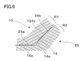
図6は、位置決め部の変形例を説明する図である。この場合、第2レンズアレイ20に設けた畝部24bの凸状面124cが平坦なテーパー面となっている。この際、第2レンズアレイ20の凸状面124cは、第1レンズアレイ10のテーパー面14aに近接又は接触する際に、面当たり状態となる。
上記第1実施形態の積層型レンズアレイユニット100によれば、第1レンズアレイ10側のテーパー面(第1当接部)14aと、第2レンズアレイ20側の凸状面(第2当接部)24cとの少なくとも一方が、他方に対して当接又は近接するテーパー状面を有するので、テーパー面14a等のテーパー状面での当接又は近接によって特定方向への相対的な移動を簡易に規制することができる。さらに、上記積層型レンズアレイユニット100では、位置決め領域(位置決め部)R1,R2が第1レンズアレイ10の縁部10rと第2レンズアレイ20の縁部20rとに沿って分布する複数箇所を含む包囲領域SRに設けられるので、上記テーパー面14aと凸状面24cとを利用した相対的な移動の規制によって、第1レンズアレイ10と第2レンズアレイ20とをこれらの縁に沿ったXY面内の並進や回転に関して省スペースで精密に位置決めすることができる。
上記のような積層型レンズアレイユニット100の場合、位置決め領域(位置決め部)R1,R2をレンズ要素10a間に設ける必要がない。仮に、位置決め領域(位置決め部)R1,R2をレンズ要素10a間、つまり周囲部分10c,20c,30cに設けると、位置決め用の凸側が厚肉になり、位置決め用の凹側が薄肉になる。このため、射出成形によって成形する際に薄肉部分に樹脂が流れにくくなり、成形樹脂圧がレンズ要素10aの部分にかかりにくくなって転写不良が生じたり、樹脂の流れが乱されてウェルドが生じたりする。一方、位置決め部をレンズ要素10aの外側、つまり縁部10r,20r,30rに設けると、薄肉になるのは外側の部分だけなので、転写不良やウェルドの問題が生じにくい。
なお、上記実施形態では、中心軸AXに対して傾斜したテーパー面14a、凸状面24c等を利用するので、第2レンズアレイ20上に第1レンズアレイ10をラフなアライメントで載置した場合にも、第1レンズアレイ10と第2レンズアレイ20とのスムーズな組み合わせと精密な位置決めとが可能になる。また、テーパー面14a、凸状面24c等からなる位置決め部が、第1及び第2レンズアレイ10,20の縁側又は外周側に配置されるので、レンズ要素10a,20a,30aの光学面の機能が損なわれることを防止でき、撮像装置1000のセンサーアレイ60の略全面を像面として活用するような設計も可能になり、高画質を達成することが容易になる。
また、上記実施形態では、クロストークの対策としてレンズ要素10a間の位置に絞り板41~43を設けているが、位置決め領域(位置決め部)R1,R2をレンズ要素10a又は支持部10bの外側に設けているので、これらが干渉することを回避しやすい。すなわち、位置決め領域(位置決め部)R1,R2をレンズ要素10a間に設けると、これらが絞り板41~43等と干渉しやすくなり、絞り板41~43を配置しにくくなってクロストークが増加する可能性がある。
なお、第1及び第2レンズアレイ10,20間の位置決め構造は上下入れ替えることができる。つまり、第1レンズアレイ10の位置決め領域(第1位置決め部)R1側に設けた境界部(第1当接部)14のテーパー面14aに図4Bに示す畝部24bの凸状面24cと同様のものを設け、第1レンズアレイ10側の凸状面と、第2レンズアレイ20のテーパー面24aとを近接又は当接させることでアライメント又は位置決めを行うことができる。
また、第1レンズアレイ10の平坦部15に設けた平坦面15aや第2レンズアレイ20の平坦部25に設けた平坦面25aは、必ずしも平坦部15,25全体に亘って延在する必要はなく、積み重ねに際して位置決めを可能にする複数箇所のみにおいて互いに当接可能に延在すれば足る。
〔第2実施形態〕
以下、第2実施形態に係る積層型レンズアレイユニット等について説明する。なお、第2実施形態の積層型レンズアレイユニット等は、第1実施形態の積層型レンズアレイユニット等を変形したものであり、特に説明しない事項は第1実施形態と同様である。
以下、第2実施形態に係る積層型レンズアレイユニット等について説明する。なお、第2実施形態の積層型レンズアレイユニット等は、第1実施形態の積層型レンズアレイユニット等を変形したものであり、特に説明しない事項は第1実施形態と同様である。
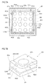
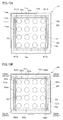
図7Aに示すように、第2レンズアレイ20の包囲領域SR内には、複数箇所の点状位置決め領域R22が存在し、各点状位置決め領域R22が位置決め部として機能する。具体的には、包囲領域SRを構成する4つの辺部分の各々において2箇所に点状位置決め領域R22が配置されている。つまり、包囲領域SRに沿って分布するように離間した状態で8つの点状位置決め領域R22が配置されている。
図7Bに示すように、点状位置決め領域R22には、第2当接部として平坦なテーパー面24aから突出するように低く短い突起部124bが形成されている。突起部124bは、俵又はラグビーボールを半分にしたような円筒に近いドーム状の外形を有し、突起部124bの表面は、半球又は円筒状に近い凸状面124cとなっている。この凸状面124cは、第1レンズアレイ10のテーパー面14aに近接又は接触する際に、厳密には線当たりであるが、位置決め上の実効性からは実質的に点当たり状態となる。なお、これ以降において、近接するが完全に接触しない場合も含めて、点線状又は短い線状の領域で近接又は接触する場合は点当たり状態と呼ぶものとする。
本実施形態の場合、第1及び第2レンズアレイ10,20の積み重ねに際して、第1レンズアレイ10側のテーパー面(第1当接部)14aと第2レンズアレイ20側の凸状面(第2当接部)124cとが近接又は接触することで自動的な位置決めが行われる。すなわち、境界部(第1当接部)14のテーパー面14aと、突起部(第2当接部)124bの凸状面(第2当接部)124cとによって、両レンズアレイ10,20をこれらの縁に沿ったXY面内の並進や回転に関して省スペースで精密に位置決めすることができる。
なお、点状位置決め領域R22については、必要最小限に間引くことができる。具体的には、図8に示すように、第2レンズアレイ20の境界部24に沿って延びる包囲領域SRを構成する4つの辺部分のうち、1つの辺部分SR1において、2箇所に点状位置決め領域R22が配置され、残りの3つの辺部分SR2において、1箇所に点状位置決め領域R22が配置されている。この場合、全辺部分SR1,SR2によってXY面内の並進が規制され、辺部分SR1単独でXY面内の回転が規制される。
〔第3実施形態〕
以下、第3実施形態に係る積層型レンズアレイユニット等について説明する。なお、第3実施形態の積層型レンズアレイユニット等は、第1及び第2実施形態の積層型レンズアレイユニットを折衷した変形例であり、特に説明しない事項は第1実施形態等と同様である。
以下、第3実施形態に係る積層型レンズアレイユニット等について説明する。なお、第3実施形態の積層型レンズアレイユニット等は、第1及び第2実施形態の積層型レンズアレイユニットを折衷した変形例であり、特に説明しない事項は第1実施形態等と同様である。
図9に示すように、包囲領域SRを構成する4つの辺部分のうち、1つの辺部分SR1において、1箇所に線状位置決め領域R2が配置され、残りの3つの辺部分SR2において、1箇所に点状位置決め領域R22が配置されている。この場合、全辺部分SR1,SR2によってXY面内の並進が規制され、辺部分SR1単独でXY面内の回転が規制される。
〔第4実施形態〕
以下、第4実施形態に係る積層型レンズアレイユニット等について説明する。なお、第4実施形態の積層型レンズアレイユニット等は、第1実施形態の積層型レンズアレイユニット等を変形したものであり、特に説明しない事項は第1実施形態と同様である。
以下、第4実施形態に係る積層型レンズアレイユニット等について説明する。なお、第4実施形態の積層型レンズアレイユニット等は、第1実施形態の積層型レンズアレイユニット等を変形したものであり、特に説明しない事項は第1実施形態と同様である。
図10Aに示すように、第1レンズアレイ10の包囲領域SR内には、複数箇所の線状位置決め領域R13が存在し、各線状位置決め領域R13が位置決め部として機能する。具体的には、包囲領域SRを構成する4つの角部分の各々において線状位置決め領域R13が配置されている。各線状位置決め領域R13には、第1当接部として境界部14、平坦の表面としてテーパー面14aが形成されている。
図10Bに示すように、第2レンズアレイ20の包囲領域SR内には、複数箇所の線状位置決め領域R23が存在し、各線状位置決め領域R23が位置決め部として機能する。具体的には、包囲領域SRを構成する4つの角部分の各々において線状位置決め領域R23が配置されている。各線状位置決め領域R23には、第2当接部として平坦なテーパー面24aから突出するように低く細長い突起部224bが形成されている。
本実施形態の場合、第1及び第2レンズアレイ10,20の積み重ねに際して、第1レンズアレイ10側の境界部(第1当接部)14のテーパー面14aと第2レンズアレイ20側の突起部(第2当接部)224bの凸状面224cとが近接又は接触することで、線当たりによる自動的な位置決めが行われる。すなわち、テーパー面(第1当接部)14aと凸状面(第2当接部)224cとによって、両レンズアレイ10,20をこれらの縁に沿ったXY面内の並進や回転に関して省スペースで精密に位置決めすることができる。
〔第5実施形態〕
以下、第5実施形態に係る積層型レンズアレイユニット等について説明する。なお、第5実施形態の積層型レンズアレイユニット等は、第1実施形態の積層型レンズアレイユニット等を変形したものであり、特に説明しない事項は第1実施形態と同様である。
以下、第5実施形態に係る積層型レンズアレイユニット等について説明する。なお、第5実施形態の積層型レンズアレイユニット等は、第1実施形態の積層型レンズアレイユニット等を変形したものであり、特に説明しない事項は第1実施形態と同様である。
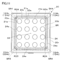
図11に示すように、第1レンズアレイ10の包囲領域SR内には、一箇所に線状位置決め領域R23が存在し、複数箇所に点状位置決め領域R24が存在し、それぞれが位置決め部として機能する。具体的には、包囲領域SRを構成する4つの角部分のうち、1つの角部分SR3において、線状位置決め領域R23が配置され、残りの3つの角部分SR4において、点状位置決め領域R24が配置されている。線状位置決め領域R23には、第4実施形態の場合と同様に、第2当接部として平坦なテーパー面24aから突出するように低く細長い突起部224bが形成されている。一方、点状位置決め領域R24には、第1実施形態の場合と同様に、第2当接部として平坦なテーパー面24aから突出するように低く短い突起部124bが形成されている。この場合、テーパー面(第1当接部)14aと凸状面(第2当接部)224cとによって線当たりによる自動的な位置決めが行われ、テーパー面(第1当接部)14aと凸状面(第2当接部)124cとによって点当たりによる自動的な位置決めが行われる。
なお、以上では、包囲領域SRを構成する4つの角部分のうち1つに長い突起部224bを設けたが、4つの角部分のうち2箇所又は3箇所に長い突起部224bを設けることもできる。
図12は、図11に示す第1レンズアレイ10の一部を変更した一例である。この場合、1つの角部分SR3又はその近傍において、1つの線状位置決め領域R23に代えて2つ一組の点状位置決め領域R25が配置されている。これら2つの点状位置決め領域R25によって、両レンズアレイ10,20をこれらの縁に沿ったXY面内の回転等に関して位置決めすることができる。
図13は、図11に示す第1レンズアレイ10の一部を変更した別の例である。この場合、2つの隣り合う角部分SR4のみが活用され、この2つの角部分SR4を構成する3つの辺部分SR1(第1~第3の辺部分)とは異なる1つの辺部分SR1(第4の辺部分SR1r)において、1つの線状位置決め領域R2が配置されている。この場合、2つの点状位置決め領域R24と1つの線状位置決め領域R2とによって、両レンズアレイ10,20をこれらの縁に沿ったXY面内の並進及び回転等に関して位置決めすることができる。2つの隣り合う角部分SR4を線当たり又は複数の点当たりとし、1つの辺部分SR1(第4の辺部分SR1r)を点当たりとすることもできる。
図14は、図11に示す第1レンズアレイ10の一部を変更した別の例である。この場合、2つの角部分SR4において2つの点状位置決め領域R24が配置され、2つの角部分SR3又はその近傍において、一対の点状位置決め領域R25からなる位置決め部がそれぞれ配置されている。XY面内の回転等に関する位置決めは、これら一対の点状位置決め領域R25によって主に達成される。
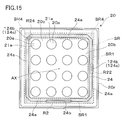
図15は、図11に示す第1レンズアレイ10の一部を変更した別の例である。この場合、1つの角部分SR4において1つの点状位置決め領域R24が配置され、角部分SR4と隣接する2つの辺部分SR1(第1及び第2の辺部分)とは異なる2つの辺部分SR1(第3及び第4の辺部分)のうち、一方において1つの線状位置決め領域R2が配置され、他方において1つの点状位置決め領域R22が配置されている。この場合、1つの線状位置決め領域R2と1つの点状位置決め領域R24とによって、両レンズアレイ10,20をこれらの縁に沿ったXY面内の並進及び回転等に関して位置決めすることができる。第3及び第4の辺部分のそれぞれに点状位置決め領域R22を設けてもよい。
〔第6実施形態〕
以下、第6実施形態に係る積層型レンズアレイユニット等について説明する。なお、第6実施形態の積層型レンズアレイユニット等は、第1実施形態の積層型レンズアレイユニット等を変形したものであり、特に説明しない事項は第1実施形態と同様である。
以下、第6実施形態に係る積層型レンズアレイユニット等について説明する。なお、第6実施形態の積層型レンズアレイユニット等は、第1実施形態の積層型レンズアレイユニット等を変形したものであり、特に説明しない事項は第1実施形態と同様である。
図16A及び16Bに示すように、第2レンズアレイ20の四角形の包囲領域SR内には、境界部24に対応する全周に亘って線状位置決め領域R26が存在し、これが位置決め部として機能する。つまり、境界部24のテーパー面24aがそのまま第2当接部として機能する。
本実施形態の場合、第1及び第2レンズアレイ10,20の積み重ねに際して、図4C等に示すような第1レンズアレイ10側の境界部(第1当接部)14のテーパー面14aと、図16A等に示すような第2レンズアレイ20側の境界部(第2当接部)24のテーパー面24aとが近接又は接触することで、自動的な位置決めが行われる。すなわち、両テーパー面14a,24aによって、両レンズアレイ10,20をこれらの縁に沿ったXY面内の並進や回転に関して省スペースで精密に位置決めすることができる。
なお、上記実施形態において、テーパー面14a,24aは、連続して延びるものである必要はなく、テーパー面14a,24aの適所に浅い窪み等を設けてテーパー面14a,24aが断続的に当接又は近接するようにできる。
〔第7実施形態〕
以下、第7実施形態に係る積層型レンズアレイユニット等について説明する。なお、第7実施形態の積層型レンズアレイユニット等は、第2実施形態の積層型レンズアレイユニット等を変形したものであり、特に説明しない事項は第2実施形態と同様である。
以下、第7実施形態に係る積層型レンズアレイユニット等について説明する。なお、第7実施形態の積層型レンズアレイユニット等は、第2実施形態の積層型レンズアレイユニット等を変形したものであり、特に説明しない事項は第2実施形態と同様である。
図17A及び17Bに示すように、縁部20rには、像側になる主面に向かって狭くなるようにややきつくテーパー面を有するテーパー部20tが設けてある。そして、このテーパー部20tの一部に、中心軸AXに平行な像側を底とする半円状の垂直基準面26aを有する突部26が設けられている。垂直基準面26aは、中心軸AXと平行となるように正確に金型に形成された成形面によって、レンズアレイ20の成形と同時に形成される。縁部20rにテーパー部20tを設けることにより、レンズアレイ20を成形型から容易に離型することができる。その一方、垂直基準面26aを設けておくことにより、例えば、レンズアレイ20の光学性能を検査機によって測定する際に、垂直基準面26aに検査機の治具等を突き当てる等して、垂直基準面26aをレンズアレイ20の検査機に対する位置決めに利用することができ、測定をスムーズに行うことができる。図示を省略しているが、垂直基準面26aは縁部20rの各辺に複数個ずつ設けられている。また、レンズアレイ10についても、その縁部10rに同様の基準面を設けることができる。縁部10r,20rに設ける垂直基準面の形状は、半円状に限らず、楕円状でもよいし、台形状や三角形状等の多角形状であってもよい。ただし、成形型からの離型を容易にするために、本実施形態と同様に、テーパーの窄み又は傾斜角に合わせて径が小さくなる形状とすることが好ましい。また、テーパー部20tの傾斜は、像側で狭くなるものに限らず、物体側で狭くなるものとできる。
なお、第2実施形態に限らず、他の実施形態においても、上述したのと同様に、縁部にテーパーを設け、さらに垂直基準面を設けるようにしてもよい。
以上、実施形態に係る積層型レンズアレイユニット等について説明したが、本発明に係る積層型レンズアレイユニット等は、上記例示のものには限られない。例えば、各レンズアレイ10,20,30を構成するレンズ要素10a,20a,30aの配列やその光学面11a,11b,…の形状等は、積層型レンズアレイユニット100又は撮像装置1000の用途又は仕様に応じて適宜変更することができる。例えばレンズ要素10a,20a,30aは、4×4の格子点に配列するものに限らず、例えば3×3、5×5等の格子点に配列することができる。なお、積層型レンズアレイユニット100を構成するレンズアレイは、上記例示の3層(レンズアレイ10,20,30)に限らず、2層(レンズアレイ10,20のみ)又は4層以上とすることができる。
上記実施形態において、テーパー面14a,24aは、完全に平坦である必要はなく、多少の凹又は凸の湾曲を有するテーパー状面とすることができる。
積層型レンズアレイユニット100又はレンズアレイ10,20,30の輪郭形状や包囲領域の形状は、一般的に矩形又は正方形、つまり四角形となるが、多少の変形が可能である。例えば角を落とした4角形に近い8角形等の輪郭(これも実質的に四角形の輪郭に含まれるものとする)を有するレンズアレイも、本発明に係る積層型レンズアレイユニットを構成する要素とできる。
以上で説明した畝部24b、突起部124b,224bの個数は、余った空間において追加することもできるが、畝部24b、突起部124b,224bの個数を少なくする方が、加工精度が要求される部分が少なくなり、部品コストを低減する観点で有利である。
Claims (13)
- それぞれ、光軸方向から見て四角形の輪郭を有し、2次元的に配列された複数のレンズ要素を有する第1レンズアレイ及び第2レンズアレイと、
前記第1レンズアレイの縁部と前記第2レンズアレイの縁部とに沿って前記複数のレンズ要素を囲む包囲領域に設けられた位置決め部とを備え、
前記位置決め部は、前記第1レンズアレイ側に配置される第1当接部と、前記第2レンズアレイ側に配置され前記第1当接部に対向する第2当接部とを有しており、前記第1及び第2レンズアレイの縁部に対応する四角形枠に平行な平面に沿った位置と当該平面に垂直な軸のまわりの回転とに関して、前記第1及び第2レンズアレイの相対的移動を規制し、
前記包囲領域より内側では、前記第1レンズアレイと前記第2レンズアレイとは互いに離れており、
前記第1及び第2当接部の少なくとも一方は、他方に対して当接又は近接するテーパー状面を有する複眼光学系用の積層型レンズアレイユニット。 - 前記位置決め部は、前記四角形枠の4つの辺部分を構成する各辺部分において少なくとも1箇所以上に設けられている、請求項1に記載の積層型レンズアレイユニット。
- 前記位置決め部は、前記各辺部分において、1箇所以上の線当たり又は複数箇所の点当たり状態となることによって位置決めを行う、請求項2に記載の積層型レンズアレイユニット。
- 前記位置決め部は、前記四角形枠の4つの角部分を構成する各角部分に設けられている、請求項1に記載の積層型レンズアレイユニット。
- 前記位置決め部は、少なくとも1つの角部分について、線当たり又は複数箇所の点当たり状態で位置決めを行う、請求項4に記載の積層型レンズアレイユニット。
- 前記位置決め部は、前記四角形枠の4つの角部分のうち隣り合う2つの角部分と、当該2つの角部分を構成する前記四角形枠の第1、第2及び第3の辺部分とは異なる第4の辺部分とに設けられており、前記2つの角部分及び前記第4の辺部分の位置決め部のうち少なくとも1つが、線当たり又は複数箇所の点当たり状態で位置決めを行う、請求項1に記載の積層型レンズアレイユニット。
- 前記位置決め部は、前記四角形枠の4つの角部分のうち1つの角部分と、当該角部分を構成する前記四角形枠の第1及び第2の辺部分とは異なる第3及び第4の辺部分のそれぞれとに設けられており、前記1つの角部分、前記第3の辺部分、及び前記第4の辺部分のうち少なくとも1つが、線当たり又は複数箇所の点当たり状態で位置決めを行う、請求項1に記載の積層型レンズアレイユニット。
- 前記第1及び第2レンズアレイは、光学材料で形成された一体物からなる、請求項1に記載の積層型レンズアレイユニット。
- 前記第1当接部と第2当接部との隙間は、10μm以下である、請求項1に記載の積層型レンズアレイユニット。
- 前記第1当接部と第2当接部とは、互いに対向する一対の平坦なテーパー面をそれぞれ有する、請求項1に記載の積層型レンズアレイユニット。
- 前記第1当接部と第2当接部とは、互いに対向する平坦なテーパー面と凸状面とをそれぞれ有する、請求項1に記載の積層型レンズアレイユニット。
- 前記第1及び第2レンズアレイの少なくとも一方は、光軸方向対して垂直な平坦面を有する平坦部を有し、前記第1及び第2レンズアレイは、前記平坦部において当接している、請求項1に記載の積層型レンズアレイユニット。
- 請求項1に記載の積層型レンズアレイユニットと、
前記積層型レンズアレイユニットを構成する複数のレンズアレイに対応して設けられたセンサーアレイと、
センサーアレイによって検出された画像信号に対して処理を行う画像処理部と、を備える撮像装置。
Priority Applications (1)
| Application Number | Priority Date | Filing Date | Title |
|---|---|---|---|
| JP2015519970A JP6380391B2 (ja) | 2013-05-31 | 2014-05-30 | 積層型レンズアレイユニット及び撮像装置 |
Applications Claiming Priority (2)
| Application Number | Priority Date | Filing Date | Title |
|---|---|---|---|
| JP2013116515 | 2013-05-31 | ||
| JP2013-116515 | 2013-05-31 |
Publications (1)
| Publication Number | Publication Date |
|---|---|
| WO2014192933A1 true WO2014192933A1 (ja) | 2014-12-04 |
Family
ID=51988951
Family Applications (1)
| Application Number | Title | Priority Date | Filing Date |
|---|---|---|---|
| PCT/JP2014/064487 Ceased WO2014192933A1 (ja) | 2013-05-31 | 2014-05-30 | 積層型レンズアレイユニット及び撮像装置 |
Country Status (2)
| Country | Link |
|---|---|
| JP (1) | JP6380391B2 (ja) |
| WO (1) | WO2014192933A1 (ja) |
Cited By (3)
| Publication number | Priority date | Publication date | Assignee | Title |
|---|---|---|---|---|
| JP2018010270A (ja) * | 2016-07-15 | 2018-01-18 | エーエーシー テクノロジーズ ピーティーイー リミテッドAac Technologies Pte.Ltd. | レンズモジュール |
| US20190259741A1 (en) * | 2015-04-20 | 2019-08-22 | Advanced Semiconductor Engineering, Inc. | Optical sensor module and method for manufacturing the same |
| KR20250073491A (ko) | 2022-10-31 | 2025-05-27 | 니혼 이타가라스 가부시키가이샤 | 렌즈 어레이 |
Families Citing this family (1)
| Publication number | Priority date | Publication date | Assignee | Title |
|---|---|---|---|---|
| KR102742270B1 (ko) * | 2019-11-11 | 2024-12-13 | 에스케이하이닉스 주식회사 | 이미지 센서 |
Citations (7)
| Publication number | Priority date | Publication date | Assignee | Title |
|---|---|---|---|---|
| JP2003329808A (ja) * | 2002-05-16 | 2003-11-19 | Olympus Optical Co Ltd | 接合レンズアレイ |
| JP2007329714A (ja) * | 2006-06-08 | 2007-12-20 | Funai Electric Co Ltd | 複眼撮像装置 |
| WO2009119192A1 (ja) * | 2008-03-26 | 2009-10-01 | コニカミノルタオプト株式会社 | 接合レンズアレイ、接合レンズ及び接合レンズアレイの製造方法 |
| JP3160406U (ja) * | 2009-04-15 | 2010-06-24 | 一品光学工業股▲ふん▼有限公司 | 方形積層ガラスレンズモジュール(Rectangularstackedglasslensmodule) |
| JP2011013577A (ja) * | 2009-07-03 | 2011-01-20 | Sharp Corp | 多層レンズ、積層型ウェハレンズおよびその製造方法 |
| WO2012165281A1 (ja) * | 2011-06-01 | 2012-12-06 | コニカミノルタアドバンストレイヤー株式会社 | 複眼ユニット |
| WO2013065455A1 (ja) * | 2011-10-31 | 2013-05-10 | コニカミノルタ株式会社 | レンズユニットの製造方法、レンズアレイ及びレンズユニット |
Family Cites Families (4)
| Publication number | Priority date | Publication date | Assignee | Title |
|---|---|---|---|---|
| JPH10170703A (ja) * | 1996-12-12 | 1998-06-26 | Ricoh Co Ltd | アレイ状レンズ及びその製造方法 |
| JP2000352606A (ja) * | 1999-06-11 | 2000-12-19 | Rohm Co Ltd | レンズアレイアッセンブリおよびこれを用いた画像表示装置 |
| JP2003095708A (ja) * | 2001-09-25 | 2003-04-03 | Olympus Optical Co Ltd | 接合レンズアレイの製造方法及び接合レンズの製造方法並びにレンズアレイ |
| DE102009055083B4 (de) * | 2009-12-21 | 2013-12-05 | Fraunhofer-Gesellschaft zur Förderung der angewandten Forschung e.V. | Optischer Schichtstapel und Verfahren zu dessen Herstellung |
-
2014
- 2014-05-30 WO PCT/JP2014/064487 patent/WO2014192933A1/ja not_active Ceased
- 2014-05-30 JP JP2015519970A patent/JP6380391B2/ja not_active Expired - Fee Related
Patent Citations (7)
| Publication number | Priority date | Publication date | Assignee | Title |
|---|---|---|---|---|
| JP2003329808A (ja) * | 2002-05-16 | 2003-11-19 | Olympus Optical Co Ltd | 接合レンズアレイ |
| JP2007329714A (ja) * | 2006-06-08 | 2007-12-20 | Funai Electric Co Ltd | 複眼撮像装置 |
| WO2009119192A1 (ja) * | 2008-03-26 | 2009-10-01 | コニカミノルタオプト株式会社 | 接合レンズアレイ、接合レンズ及び接合レンズアレイの製造方法 |
| JP3160406U (ja) * | 2009-04-15 | 2010-06-24 | 一品光学工業股▲ふん▼有限公司 | 方形積層ガラスレンズモジュール(Rectangularstackedglasslensmodule) |
| JP2011013577A (ja) * | 2009-07-03 | 2011-01-20 | Sharp Corp | 多層レンズ、積層型ウェハレンズおよびその製造方法 |
| WO2012165281A1 (ja) * | 2011-06-01 | 2012-12-06 | コニカミノルタアドバンストレイヤー株式会社 | 複眼ユニット |
| WO2013065455A1 (ja) * | 2011-10-31 | 2013-05-10 | コニカミノルタ株式会社 | レンズユニットの製造方法、レンズアレイ及びレンズユニット |
Cited By (4)
| Publication number | Priority date | Publication date | Assignee | Title |
|---|---|---|---|---|
| US20190259741A1 (en) * | 2015-04-20 | 2019-08-22 | Advanced Semiconductor Engineering, Inc. | Optical sensor module and method for manufacturing the same |
| US11257799B2 (en) * | 2015-04-20 | 2022-02-22 | Advanced Semiconductor Engineering, Inc. | Optical sensor module and method for manufacturing the same |
| JP2018010270A (ja) * | 2016-07-15 | 2018-01-18 | エーエーシー テクノロジーズ ピーティーイー リミテッドAac Technologies Pte.Ltd. | レンズモジュール |
| KR20250073491A (ko) | 2022-10-31 | 2025-05-27 | 니혼 이타가라스 가부시키가이샤 | 렌즈 어레이 |
Also Published As
| Publication number | Publication date |
|---|---|
| JPWO2014192933A1 (ja) | 2017-02-23 |
| JP6380391B2 (ja) | 2018-08-29 |
Similar Documents
| Publication | Publication Date | Title |
|---|---|---|
| JP6380391B2 (ja) | 積層型レンズアレイユニット及び撮像装置 | |
| JP5812521B2 (ja) | 複眼ユニット | |
| TWI544248B (zh) | 攝像透鏡單元之製造方法、以及攝像透鏡單元 | |
| WO2018023887A1 (zh) | 摄像模组及其模塑电路板组件和模塑感光组件和制造方法 | |
| TW201806087A (zh) | 攝像模組及其模塑電路板元件與製造方法 | |
| CN107077062A (zh) | 表皮用支承框及制造方法 | |
| WO2012043191A1 (ja) | ガラスレンズ | |
| TWM557833U (zh) | 攝像模組、模塑感光元件、成型模具及其電子設備 | |
| WO2009119192A1 (ja) | 接合レンズアレイ、接合レンズ及び接合レンズアレイの製造方法 | |
| WO2011093502A1 (ja) | レンズユニットの製造方法、撮像装置、金型の製造方法、成形金型及びガラスレンズアレイの成形方法 | |
| JP2013174784A (ja) | カメラモジュール、カメラモジュールの組み付け方法、レンズアレイの製造方法及び金型 | |
| TWI432815B (zh) | 鏡頭模組 | |
| JP2012154825A (ja) | 撮像モジュール | |
| JP6536955B2 (ja) | レンズアレイ、レンズアレイ積層体、及び、これらの製造方法 | |
| JP5345455B2 (ja) | 多層レンズ、積層型ウェハレンズおよびその製造方法 | |
| WO2014119751A1 (ja) | レンズアレイ、複眼光学系、及びレンズアレイの製造方法 | |
| JP2010147917A (ja) | 撮像素子ユニット及び撮像装置 | |
| JP2014235307A (ja) | レンズアレイユニット及び撮像装置 | |
| JP6439604B2 (ja) | 光学素子及び光学素子の製造方法 | |
| WO2014119737A1 (ja) | 複眼光学系、撮像装置、及び複眼光学系の製造方法 | |
| JP2006235262A (ja) | 光コリメータアレイ | |
| JP7665414B2 (ja) | プラスチックレンズおよび機器 | |
| JP5254139B2 (ja) | 多層レンズ、積層型ウェハレンズおよびその製造方法 | |
| JPWO2014119738A1 (ja) | 複眼光学系、撮像装置、及び複眼光学系の製造方法 | |
| JP2006100312A (ja) | 光半導体装置および測距モジュール |
Legal Events
| Date | Code | Title | Description |
|---|---|---|---|
| 121 | Ep: the epo has been informed by wipo that ep was designated in this application |
Ref document number: 14803453 Country of ref document: EP Kind code of ref document: A1 |
|
| ENP | Entry into the national phase |
Ref document number: 2015519970 Country of ref document: JP Kind code of ref document: A |
|
| NENP | Non-entry into the national phase |
Ref country code: DE |
|
| 122 | Ep: pct application non-entry in european phase |
Ref document number: 14803453 Country of ref document: EP Kind code of ref document: A1 |