WO2014192872A1 - 極端紫外光生成システム - Google Patents
極端紫外光生成システム Download PDFInfo
- Publication number
- WO2014192872A1 WO2014192872A1 PCT/JP2014/064265 JP2014064265W WO2014192872A1 WO 2014192872 A1 WO2014192872 A1 WO 2014192872A1 JP 2014064265 W JP2014064265 W JP 2014064265W WO 2014192872 A1 WO2014192872 A1 WO 2014192872A1
- Authority
- WO
- WIPO (PCT)
- Prior art keywords
- laser beam
- pulse laser
- target
- light
- prepulse
- Prior art date
- Legal status (The legal status is an assumption and is not a legal conclusion. Google has not performed a legal analysis and makes no representation as to the accuracy of the status listed.)
- Ceased
Links
Images

















Classifications
-
- H—ELECTRICITY
- H05—ELECTRIC TECHNIQUES NOT OTHERWISE PROVIDED FOR
- H05G—X-RAY TECHNIQUE
- H05G2/00—Apparatus or processes specially adapted for producing X-rays, not involving X-ray tubes, e.g. involving generation of a plasma
- H05G2/001—Production of X-ray radiation generated from plasma
- H05G2/008—Production of X-ray radiation generated from plasma involving an energy-carrying beam in the process of plasma generation
- H05G2/0082—Production of X-ray radiation generated from plasma involving an energy-carrying beam in the process of plasma generation the energy-carrying beam being a laser beam
- H05G2/0088—Production of X-ray radiation generated from plasma involving an energy-carrying beam in the process of plasma generation the energy-carrying beam being a laser beam for preconditioning the plasma generating material
-
- G—PHYSICS
- G03—PHOTOGRAPHY; CINEMATOGRAPHY; ANALOGOUS TECHNIQUES USING WAVES OTHER THAN OPTICAL WAVES; ELECTROGRAPHY; HOLOGRAPHY
- G03F—PHOTOMECHANICAL PRODUCTION OF TEXTURED OR PATTERNED SURFACES, e.g. FOR PRINTING, FOR PROCESSING OF SEMICONDUCTOR DEVICES; MATERIALS THEREFOR; ORIGINALS THEREFOR; APPARATUS SPECIALLY ADAPTED THEREFOR
- G03F7/00—Photomechanical, e.g. photolithographic, production of textured or patterned surfaces, e.g. printing surfaces; Materials therefor, e.g. comprising photoresists; Apparatus specially adapted therefor
- G03F7/70—Microphotolithographic exposure; Apparatus therefor
- G03F7/70008—Production of exposure light, i.e. light sources
- G03F7/70033—Production of exposure light, i.e. light sources by plasma extreme ultraviolet [EUV] sources
-
- G—PHYSICS
- G03—PHOTOGRAPHY; CINEMATOGRAPHY; ANALOGOUS TECHNIQUES USING WAVES OTHER THAN OPTICAL WAVES; ELECTROGRAPHY; HOLOGRAPHY
- G03F—PHOTOMECHANICAL PRODUCTION OF TEXTURED OR PATTERNED SURFACES, e.g. FOR PRINTING, FOR PROCESSING OF SEMICONDUCTOR DEVICES; MATERIALS THEREFOR; ORIGINALS THEREFOR; APPARATUS SPECIALLY ADAPTED THEREFOR
- G03F7/00—Photomechanical, e.g. photolithographic, production of textured or patterned surfaces, e.g. printing surfaces; Materials therefor, e.g. comprising photoresists; Apparatus specially adapted therefor
- G03F7/70—Microphotolithographic exposure; Apparatus therefor
- G03F7/708—Construction of apparatus, e.g. environment aspects, hygiene aspects or materials
- G03F7/70991—Connection with other apparatus, e.g. multiple exposure stations, particular arrangement of exposure apparatus and pre-exposure and/or post-exposure apparatus; Shared apparatus, e.g. having shared radiation source, shared mask or workpiece stage, shared base-plate; Utilities, e.g. cable, pipe or wireless arrangements for data, power, fluids or vacuum
-
- H—ELECTRICITY
- H01—ELECTRIC ELEMENTS
- H01S—DEVICES USING THE PROCESS OF LIGHT AMPLIFICATION BY STIMULATED EMISSION OF RADIATION [LASER] TO AMPLIFY OR GENERATE LIGHT; DEVICES USING STIMULATED EMISSION OF ELECTROMAGNETIC RADIATION IN WAVE RANGES OTHER THAN OPTICAL
- H01S3/00—Lasers, i.e. devices using stimulated emission of electromagnetic radiation in the infrared, visible or ultraviolet wave range
- H01S3/05—Construction or shape of optical resonators; Accommodation of active medium therein; Shape of active medium
- H01S3/06—Construction or shape of active medium
- H01S3/0602—Crystal lasers or glass lasers
-
- H—ELECTRICITY
- H01—ELECTRIC ELEMENTS
- H01S—DEVICES USING THE PROCESS OF LIGHT AMPLIFICATION BY STIMULATED EMISSION OF RADIATION [LASER] TO AMPLIFY OR GENERATE LIGHT; DEVICES USING STIMULATED EMISSION OF ELECTROMAGNETIC RADIATION IN WAVE RANGES OTHER THAN OPTICAL
- H01S3/00—Lasers, i.e. devices using stimulated emission of electromagnetic radiation in the infrared, visible or ultraviolet wave range
- H01S3/05—Construction or shape of optical resonators; Accommodation of active medium therein; Shape of active medium
- H01S3/08—Construction or shape of optical resonators or components thereof
- H01S3/08054—Passive cavity elements acting on the polarization, e.g. a polarizer for branching or walk-off compensation
-
- H—ELECTRICITY
- H01—ELECTRIC ELEMENTS
- H01S—DEVICES USING THE PROCESS OF LIGHT AMPLIFICATION BY STIMULATED EMISSION OF RADIATION [LASER] TO AMPLIFY OR GENERATE LIGHT; DEVICES USING STIMULATED EMISSION OF ELECTROMAGNETIC RADIATION IN WAVE RANGES OTHER THAN OPTICAL
- H01S3/00—Lasers, i.e. devices using stimulated emission of electromagnetic radiation in the infrared, visible or ultraviolet wave range
- H01S3/10—Controlling the intensity, frequency, phase, polarisation or direction of the emitted radiation, e.g. switching, gating, modulating or demodulating
- H01S3/106—Controlling the intensity, frequency, phase, polarisation or direction of the emitted radiation, e.g. switching, gating, modulating or demodulating by controlling devices placed within the cavity
- H01S3/107—Controlling the intensity, frequency, phase, polarisation or direction of the emitted radiation, e.g. switching, gating, modulating or demodulating by controlling devices placed within the cavity using electro-optic devices, e.g. exhibiting Pockels or Kerr effect
-
- H—ELECTRICITY
- H01—ELECTRIC ELEMENTS
- H01S—DEVICES USING THE PROCESS OF LIGHT AMPLIFICATION BY STIMULATED EMISSION OF RADIATION [LASER] TO AMPLIFY OR GENERATE LIGHT; DEVICES USING STIMULATED EMISSION OF ELECTROMAGNETIC RADIATION IN WAVE RANGES OTHER THAN OPTICAL
- H01S3/00—Lasers, i.e. devices using stimulated emission of electromagnetic radiation in the infrared, visible or ultraviolet wave range
- H01S3/10—Controlling the intensity, frequency, phase, polarisation or direction of the emitted radiation, e.g. switching, gating, modulating or demodulating
- H01S3/11—Mode locking; Q-switching; Other giant-pulse techniques, e.g. cavity dumping
- H01S3/1106—Mode locking
- H01S3/1112—Passive mode locking
- H01S3/1115—Passive mode locking using intracavity saturable absorbers
-
- H—ELECTRICITY
- H01—ELECTRIC ELEMENTS
- H01S—DEVICES USING THE PROCESS OF LIGHT AMPLIFICATION BY STIMULATED EMISSION OF RADIATION [LASER] TO AMPLIFY OR GENERATE LIGHT; DEVICES USING STIMULATED EMISSION OF ELECTROMAGNETIC RADIATION IN WAVE RANGES OTHER THAN OPTICAL
- H01S3/00—Lasers, i.e. devices using stimulated emission of electromagnetic radiation in the infrared, visible or ultraviolet wave range
- H01S3/14—Lasers, i.e. devices using stimulated emission of electromagnetic radiation in the infrared, visible or ultraviolet wave range characterised by the material used as the active medium
- H01S3/22—Gases
- H01S3/223—Gases the active gas being polyatomic, i.e. containing two or more atoms
- H01S3/2232—Carbon dioxide (CO2) or monoxide [CO]
-
- H—ELECTRICITY
- H01—ELECTRIC ELEMENTS
- H01S—DEVICES USING THE PROCESS OF LIGHT AMPLIFICATION BY STIMULATED EMISSION OF RADIATION [LASER] TO AMPLIFY OR GENERATE LIGHT; DEVICES USING STIMULATED EMISSION OF ELECTROMAGNETIC RADIATION IN WAVE RANGES OTHER THAN OPTICAL
- H01S3/00—Lasers, i.e. devices using stimulated emission of electromagnetic radiation in the infrared, visible or ultraviolet wave range
- H01S3/23—Arrangements of two or more lasers not provided for in groups H01S3/02 - H01S3/22, e.g. tandem arrangements of separate active media
- H01S3/2308—Amplifier arrangements, e.g. MOPA
-
- H—ELECTRICITY
- H05—ELECTRIC TECHNIQUES NOT OTHERWISE PROVIDED FOR
- H05G—X-RAY TECHNIQUE
- H05G2/00—Apparatus or processes specially adapted for producing X-rays, not involving X-ray tubes, e.g. involving generation of a plasma
- H05G2/001—Production of X-ray radiation generated from plasma
- H05G2/008—Production of X-ray radiation generated from plasma involving an energy-carrying beam in the process of plasma generation
- H05G2/0082—Production of X-ray radiation generated from plasma involving an energy-carrying beam in the process of plasma generation the energy-carrying beam being a laser beam
- H05G2/0084—Control of the laser beam
-
- H—ELECTRICITY
- H01—ELECTRIC ELEMENTS
- H01S—DEVICES USING THE PROCESS OF LIGHT AMPLIFICATION BY STIMULATED EMISSION OF RADIATION [LASER] TO AMPLIFY OR GENERATE LIGHT; DEVICES USING STIMULATED EMISSION OF ELECTROMAGNETIC RADIATION IN WAVE RANGES OTHER THAN OPTICAL
- H01S3/00—Lasers, i.e. devices using stimulated emission of electromagnetic radiation in the infrared, visible or ultraviolet wave range
- H01S3/005—Optical devices external to the laser cavity, specially adapted for lasers, e.g. for homogenisation of the beam or for manipulating laser pulses, e.g. pulse shaping
-
- H—ELECTRICITY
- H01—ELECTRIC ELEMENTS
- H01S—DEVICES USING THE PROCESS OF LIGHT AMPLIFICATION BY STIMULATED EMISSION OF RADIATION [LASER] TO AMPLIFY OR GENERATE LIGHT; DEVICES USING STIMULATED EMISSION OF ELECTROMAGNETIC RADIATION IN WAVE RANGES OTHER THAN OPTICAL
- H01S3/00—Lasers, i.e. devices using stimulated emission of electromagnetic radiation in the infrared, visible or ultraviolet wave range
- H01S3/005—Optical devices external to the laser cavity, specially adapted for lasers, e.g. for homogenisation of the beam or for manipulating laser pulses, e.g. pulse shaping
- H01S3/0085—Modulating the output, i.e. the laser beam is modulated outside the laser cavity
-
- H—ELECTRICITY
- H01—ELECTRIC ELEMENTS
- H01S—DEVICES USING THE PROCESS OF LIGHT AMPLIFICATION BY STIMULATED EMISSION OF RADIATION [LASER] TO AMPLIFY OR GENERATE LIGHT; DEVICES USING STIMULATED EMISSION OF ELECTROMAGNETIC RADIATION IN WAVE RANGES OTHER THAN OPTICAL
- H01S3/00—Lasers, i.e. devices using stimulated emission of electromagnetic radiation in the infrared, visible or ultraviolet wave range
- H01S3/10—Controlling the intensity, frequency, phase, polarisation or direction of the emitted radiation, e.g. switching, gating, modulating or demodulating
- H01S3/102—Controlling the intensity, frequency, phase, polarisation or direction of the emitted radiation, e.g. switching, gating, modulating or demodulating by controlling the active medium, e.g. by controlling the processes or apparatus for excitation
-
- H—ELECTRICITY
- H01—ELECTRIC ELEMENTS
- H01S—DEVICES USING THE PROCESS OF LIGHT AMPLIFICATION BY STIMULATED EMISSION OF RADIATION [LASER] TO AMPLIFY OR GENERATE LIGHT; DEVICES USING STIMULATED EMISSION OF ELECTROMAGNETIC RADIATION IN WAVE RANGES OTHER THAN OPTICAL
- H01S3/00—Lasers, i.e. devices using stimulated emission of electromagnetic radiation in the infrared, visible or ultraviolet wave range
- H01S3/14—Lasers, i.e. devices using stimulated emission of electromagnetic radiation in the infrared, visible or ultraviolet wave range characterised by the material used as the active medium
- H01S3/16—Solid materials
- H01S3/1601—Solid materials characterised by an active (lasing) ion
- H01S3/1603—Solid materials characterised by an active (lasing) ion rare earth
- H01S3/1611—Solid materials characterised by an active (lasing) ion rare earth neodymium
-
- H—ELECTRICITY
- H01—ELECTRIC ELEMENTS
- H01S—DEVICES USING THE PROCESS OF LIGHT AMPLIFICATION BY STIMULATED EMISSION OF RADIATION [LASER] TO AMPLIFY OR GENERATE LIGHT; DEVICES USING STIMULATED EMISSION OF ELECTROMAGNETIC RADIATION IN WAVE RANGES OTHER THAN OPTICAL
- H01S3/00—Lasers, i.e. devices using stimulated emission of electromagnetic radiation in the infrared, visible or ultraviolet wave range
- H01S3/14—Lasers, i.e. devices using stimulated emission of electromagnetic radiation in the infrared, visible or ultraviolet wave range characterised by the material used as the active medium
- H01S3/16—Solid materials
- H01S3/163—Solid materials characterised by a crystal matrix
- H01S3/164—Solid materials characterised by a crystal matrix garnet
- H01S3/1643—YAG
-
- H—ELECTRICITY
- H01—ELECTRIC ELEMENTS
- H01S—DEVICES USING THE PROCESS OF LIGHT AMPLIFICATION BY STIMULATED EMISSION OF RADIATION [LASER] TO AMPLIFY OR GENERATE LIGHT; DEVICES USING STIMULATED EMISSION OF ELECTROMAGNETIC RADIATION IN WAVE RANGES OTHER THAN OPTICAL
- H01S3/00—Lasers, i.e. devices using stimulated emission of electromagnetic radiation in the infrared, visible or ultraviolet wave range
- H01S3/14—Lasers, i.e. devices using stimulated emission of electromagnetic radiation in the infrared, visible or ultraviolet wave range characterised by the material used as the active medium
- H01S3/16—Solid materials
- H01S3/163—Solid materials characterised by a crystal matrix
- H01S3/1671—Solid materials characterised by a crystal matrix vanadate, niobate, tantalate
- H01S3/1673—YVO4 [YVO]
-
- H—ELECTRICITY
- H01—ELECTRIC ELEMENTS
- H01S—DEVICES USING THE PROCESS OF LIGHT AMPLIFICATION BY STIMULATED EMISSION OF RADIATION [LASER] TO AMPLIFY OR GENERATE LIGHT; DEVICES USING STIMULATED EMISSION OF ELECTROMAGNETIC RADIATION IN WAVE RANGES OTHER THAN OPTICAL
- H01S3/00—Lasers, i.e. devices using stimulated emission of electromagnetic radiation in the infrared, visible or ultraviolet wave range
- H01S3/23—Arrangements of two or more lasers not provided for in groups H01S3/02 - H01S3/22, e.g. tandem arrangements of separate active media
- H01S3/2308—Amplifier arrangements, e.g. MOPA
- H01S3/2316—Cascaded amplifiers
-
- H—ELECTRICITY
- H01—ELECTRIC ELEMENTS
- H01S—DEVICES USING THE PROCESS OF LIGHT AMPLIFICATION BY STIMULATED EMISSION OF RADIATION [LASER] TO AMPLIFY OR GENERATE LIGHT; DEVICES USING STIMULATED EMISSION OF ELECTROMAGNETIC RADIATION IN WAVE RANGES OTHER THAN OPTICAL
- H01S3/00—Lasers, i.e. devices using stimulated emission of electromagnetic radiation in the infrared, visible or ultraviolet wave range
- H01S3/23—Arrangements of two or more lasers not provided for in groups H01S3/02 - H01S3/22, e.g. tandem arrangements of separate active media
- H01S3/2308—Amplifier arrangements, e.g. MOPA
- H01S3/2325—Multi-pass amplifiers, e.g. regenerative amplifiers
- H01S3/235—Regenerative amplifiers
Definitions
- the present disclosure relates to an extreme ultraviolet light generation system.
- an LPP Laser Produced Plasma
- a DPP Downlink Physical Transport Stream
- SR Synchrotron Radiation
- an extreme ultraviolet light generation system includes: a chamber; a target generation unit configured to output a target toward a plasma generation region in the chamber; A laser system that generates a first prepulse laser beam, a second prepulse laser beam, and a main pulse laser beam so that the second prepulse laser beam and the main pulse laser beam are irradiated in this order, and a fluence of the second prepulse laser beam And a controller configured to control the laser system such that the laser beam intensity is 1 J / cm 2 or more and less than the fluence of the main pulse laser beam.
- an extreme ultraviolet light generation system includes: a chamber; a target generation unit configured to output a target toward a plasma generation region in the chamber;
- the laser system that generates the pre-pulse laser beam and the main pulse laser beam so that the main pulse laser beam is irradiated in this order, and the pulse waveform of the main pulse laser beam have light intensities at an increase rate less than the first increase rate Includes a first step in which the light intensity increases, a second step in which the light intensity increases at an increase rate equal to or greater than a second increase rate greater than the first increase rate, and a third step in which the light intensity decreases.
- the fluence of the main pulse laser light in the first stage is 2 J / cm 2 or more, and the fluence of the main pulse laser light in the second and third stages.
- an extreme ultraviolet light generation system includes: a chamber; a target generation unit configured to output a target toward a plasma generation region in the chamber; The first pre-pulse laser beam is irradiated so that the main pulse laser beam having a wavelength larger than the light, the second pre-pulse laser beam, and the wavelength of the first pre-pulse laser beam and the wavelength of the second pre-pulse laser beam is irradiated in this order.
- a laser system configured to generate a second pre-pulse laser beam and a main pulse laser beam
- a laser focusing device configured to focus the first pre-pulse laser beam, the second pre-pulse laser beam and the main pulse laser beam on a plasma generation region
- the beam diameter of the second pre-pulse laser beam incident on the optical system and the laser focusing optical system is the laser focused beam.
- the first pre-pulse laser beam, the second pre-pulse laser beam, and the main pulse laser beam are smaller than the beam diameter of the first pre-pulse laser beam incident on the system and the beam diameter of the main pulse laser beam incident on the laser focusing optical system
- a controller configured to control at least one beam diameter of
- an extreme ultraviolet light generation system includes: a chamber; a target generation unit configured to output a target toward a plasma generation region in the chamber; A laser system for generating a first prepulse laser beam, a second prepulse laser beam and a main pulse laser beam so that light, second prepulse laser beam and main pulse laser beam are irradiated in this order, and first prepulse for the target At least one laser optical axis of the first pre-pulse laser beam and the main pulse laser beam is controlled such that the irradiation position of the laser beam is closer to the target generation unit than the irradiation position of the main pulse laser beam on the target And a controller.
- an extreme ultraviolet light generation system includes: a chamber; a target generation unit configured to output a target toward a plasma generation region in the chamber; A laser system generating a first prepulse laser beam, a second prepulse laser beam, and a main pulse laser beam such that the light, the second prepulse laser beam, and the main pulse laser beam are irradiated in this order; The difference between the wavelength of the second prepulse laser beam and the wavelength of the main pulse laser beam may be smaller than the difference between the wavelength of the prepulse laser beam and the wavelength of the second prepulse laser beam.
- an extreme ultraviolet light generation system includes: a chamber; a target generation unit configured to output a target toward a plasma generation region in the chamber; A laser system for generating a first prepulse laser beam, a second prepulse laser beam and a main pulse laser beam so that light, second prepulse laser beam and main pulse laser beam are irradiated in this order, and first prepulse for the target
- the time from the irradiation timing of the laser light to the irradiation timing of the second pre-pulse laser light to the target is shorter than the time from the irradiation timing of the second pre-pulse laser light to the target to the irradiation timing of the main pulse laser light to the target
- a control unit may include a.
- FIG. 1 schematically shows the configuration of an exemplary LPP-type EUV light generation system.
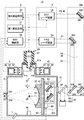
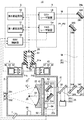
- FIG. 2 is a partial cross-sectional view showing the configuration of the EUV light generation system according to the first embodiment.
- FIG. 3 is a waveform diagram showing an example of a laser reception signal in the first embodiment.
- FIG. 4 schematically shows a first configuration example of a laser light traveling direction control unit and its periphery in the EUV light generation system shown in FIG.
- FIG. 5 schematically shows a second configuration example of the laser light traveling direction control unit and its periphery in the EUV light generation system shown in FIG.
- FIG. 1 schematically shows the configuration of an exemplary LPP-type EUV light generation system.
- FIG. 2 is a partial cross-sectional view showing the configuration of the EUV light generation system according to the first embodiment.
- FIG. 3 is a waveform diagram showing an example of a laser reception signal in the first embodiment.
- FIG. 4 schematically shows a first configuration example of a laser light traveling direction control
- FIG. 6 schematically illustrates a third configuration example of the laser light traveling direction control unit in the EUV light generation system shown in FIG. 2 and the periphery thereof.
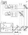
- FIG. 7 is a partial cross-sectional view showing the configuration of the EUV light generation system according to the second embodiment.
- FIG. 8 is a waveform diagram showing an example of a laser reception signal in the second embodiment.
- FIG. 9 schematically shows a configuration example of a laser light traveling direction control unit and its periphery in the EUV light generation system shown in FIG.
- FIG. 10 is a waveform diagram showing another example of the laser reception signal in the second embodiment.
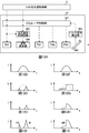
- FIG. 11A schematically shows a first configuration example of the CO 2 laser device in the second embodiment.
- FIG. 11A schematically shows a first configuration example of the CO 2 laser device in the second embodiment.
- FIG. 11B is a graph showing a first example of the pulse waveform of the first seed laser light output from the first master oscillator.
- FIG. 11C is a graph showing a first example of the pulse waveform of the second seed laser light output from the second master oscillator.
- FIG. 11D is a graph showing a first example of a pulse waveform of pulsed laser light output from a beam combiner.
- FIG. 11E is a graph showing a first example of a pulse waveform of pulsed laser light output from a CO 2 laser device.
- FIG. 11F is a graph showing a second example of the pulse waveform of the first seed laser light output from the first master oscillator.
- FIG. 11G is a graph showing a second example of the pulse waveform of the second seed laser light output from the second master oscillator.
- FIG. 11H is a graph showing a second example of the pulse waveform of pulsed laser light output from the beam combiner.
- FIG. 11I is a graph showing a second example of a pulse waveform of pulsed laser light output from a CO 2 laser device.
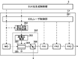
- FIG. 12A schematically shows a second configuration example of the CO 2 laser device in the second embodiment.
- FIG. 12B is a graph showing a first example of a pulse waveform of pulse laser light output from the master oscillator.
- FIG. 12C is a graph showing a first example of the voltage waveform output from the voltage waveform control circuit.
- FIG. 12A schematically shows a second configuration example of the CO 2 laser device in the second embodiment.
- FIG. 12B is a graph showing a first example of a pulse waveform of pulse laser light output from the master oscillator.
- FIG. 12C is a
- FIG. 12D is a graph showing a first example of a pulse waveform of pulsed laser light output from a waveform controller.
- FIG. 12E is a graph showing a first example of the pulse waveform of pulsed laser light output from the third amplifier.
- FIG. 12F is a graph showing a second example of the pulse waveform of pulse laser light output from the master oscillator.
- FIG. 12G is a graph showing a second example of the voltage waveform output from the voltage waveform control circuit.
- FIG. 12H is a graph showing a second example of the pulse waveform of the pulsed laser light output from the waveform controller.
- FIG. 12I is a graph showing a second example of the pulse waveform of pulsed laser light output from the third amplifier.
- FIG. 13 schematically shows an example of the configuration of the CO 2 laser device shown in FIG. 12A.
- FIG. 14 schematically illustrates a third configuration example of the CO 2 laser device in the second embodiment.
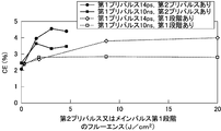
- FIG. 15 is a graph showing measurement results of CE in the EUV light generation system according to the first and second embodiments.
- FIG. 16 is a graph showing measurement results of CE in the EUV light generation system according to the first and second embodiments.
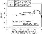
- FIG. 17 is another graph showing the measurement results of CE in the EUV light generation system according to the first embodiment.
- FIG. 18 is another graph showing the measurement results of CE in the EUV light generation system according to the first embodiment.
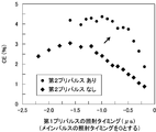
- FIG. 19 is still another graph showing the measurement results of CE in the EUV light generation system according to the first and second embodiments.
- FIG. 20 is still another graph showing the measurement results of CE in the EUV light generation system according to the first and second embodiments.
- FIG. 21 is still another graph showing the measurement results of CE in the EUV light generation system according to the first embodiment.
- FIG. 22 is still another graph showing the measurement results of CE in the EUV light generation system according to the first embodiment.
- FIG. 23 is still another graph showing the measurement results of CE in the EUV light generation system according to the first embodiment.
- FIG. 24 is still another graph showing the measurement results of CE in the EUV light generation system according to the first embodiment.
- FIG. 25 is still another graph showing the measurement results of CE in the EUV light generation system according to the first embodiment.
- FIG. 26A schematically shows the appearance of a target when irradiated with a first pre-pulse laser beam having a pulse width on the order of picoseconds in the first and second embodiments.
- FIG. 26B schematically shows the appearance of the target when it is irradiated with the second pre-pulse laser beam.
- FIG. 26C schematically shows the state of the target when the main pulse laser beam is irradiated.
- FIG. 26D schematically shows the state of the target after being irradiated with the main pulse laser beam.
- FIG. 27A schematically shows the appearance of the target when irradiated with the first pre-pulse laser beam having a pulse width on the nanosecond order in the first and second embodiments.
- FIG. 27B schematically shows the appearance of the target when it is irradiated with the second pre-pulse laser beam.
- FIG. 27C schematically shows the state of the target when the main pulse laser beam is irradiated.
- FIG. 27D schematically illustrates the target after being irradiated with the main pulse laser beam.
- FIG. 28 is a partial cross-sectional view showing the configuration of the EUV light generation system according to the third embodiment.
- FIG. 29 is a waveform diagram showing an example of a laser reception signal in the third embodiment.
- FIG. 30 schematically shows a configuration example of a laser beam traveling direction control unit and its periphery in the EUV light generation system shown in FIG. FIG.
- FIG. 31 is a partial cross-sectional view showing a modification of the EUV light generation system according to the third embodiment.
- FIG. 32 is a waveform diagram showing an example of a laser reception signal in the modification of the third embodiment.
- FIG. 33 is a graph showing the measurement results of CE in the EUV light generation system according to the third embodiment.
- FIG. 34 schematically illustrates the target after being irradiated with the first prepulse laser beam and the second prepulse laser beam in the third embodiment.
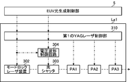
- FIG. 35 schematically shows a first example of a first YAG laser apparatus that can be used in the EUV light generation system according to each of the above-described embodiments.
- FIG. 36 schematically illustrates a second example of the first YAG laser device that can be used in the EUV light generation system according to each of the embodiments described above.
- FIG. 37 schematically shows an optical path when a voltage is applied to the Pockels cell in the regenerative amplifier shown in FIG.
- FIG. 38 is a block diagram showing a schematic configuration of a control unit.
- EUV light generation system in which a YAG laser device outputs a plurality of pulses 8.1 Configuration 8.2 Operation 8.3 Example of laser optical system 8.4 Modification using fourth trigger signal 8.5 Improvement of CE 8 .6 Change in target irradiated with pulsed laser light Other (YAG laser device) 9.1 First example 9.2 Second example 9.2.1 When no voltage is applied to Pockels cell 9.2.2 When voltage is applied to Pockels cell 10. Configuration of control unit
- a target generation unit may output a droplet-like target to reach a plasma generation region in a chamber.
- the laser system irradiates the target with pulsed laser light, whereby the target becomes plasma and EUV light can be emitted from this plasma.
- the emitted EUV light may be collected by an EUV collector mirror disposed in the chamber and output to an exposure apparatus or the like.
- an EUV light generation system may be configured.
- the droplet-like target with the first pre-pulse laser beam the droplet-like target may be broken into fine particles and expand.
- the target By irradiating the target with the second pre-pulse laser beam, the target can be vapor or pre-plasma.
- the main pulse laser beam By irradiating the main pulse laser beam to the vapor or the pre-plasma, it can be efficiently converted to plasma.
- the “orbit” of the target may be an ideal path of the target output from the target generation unit or a path of the target according to the design of the target generation unit.
- the “locus” of the target may be the actual path of the target output from the target generator.
- “Plasma generation region” may mean a region where generation of plasma for generating EUV light is started.
- the “optical path axis” of the pulsed laser light may mean the central axis of the optical path of the pulsed laser light.
- FIG. 1 schematically shows the configuration of an exemplary LPP-type EUV light generation system.
- the EUV light generation device 1 may be used with at least one laser system 3.
- a system including the EUV light generation apparatus 1 and the laser system 3 is referred to as an EUV light generation system 11.
- the EUV light generation system 1 may include a chamber 2 and a target generation unit 26. Chamber 2 may be sealable.
- the target generation unit 26 may be attached, for example, to penetrate the wall of the chamber 2.
- the material of the target material output from the target generation unit 26 may include, but is not limited to, tin, terbium, gadolinium, lithium, xenon, or any combination of two or more thereof.
- the wall of the chamber 2 may be provided with at least one through hole.
- a window 21 may be provided in the through hole, and pulsed laser light 32 output from the laser system 3 may be transmitted through the window 21.
- an EUV collector mirror 23 having a spheroidal reflecting surface may be disposed inside the chamber 2, for example.
- the EUV collector mirror 23 may have first and second focal points.
- a multilayer reflective film in which molybdenum and silicon are alternately stacked may be formed on the surface of the EUV collector mirror 23.
- the EUV collector mirror 23 is preferably arranged, for example, such that its first focal point is located at the plasma generation region 25 and its second focal point is located at the intermediate focusing point (IF) 292.
- a through hole 24 may be provided in the central portion of the EUV collector mirror 23, and the pulse laser beam 33 may pass through the through hole 24.
- the EUV light generation apparatus 1 may include an EUV light generation controller 5, a target sensor 4 and the like.
- the target sensor 4 may have an imaging function, and may be configured to detect the presence, trajectory, position, velocity and the like of the target 27.
- the EUV light generation apparatus 1 may include a connection part 29 that brings the inside of the chamber 2 into communication with the inside of the exposure apparatus 6. Inside the connection portion 29, a wall 291 in which an aperture is formed may be provided. The wall 291 may be arranged such that its aperture is at a second focal position of the EUV collector mirror 23.
- the EUV light generation apparatus 1 may include a laser beam traveling direction control unit 34, a laser beam focusing mirror 22, a target recovery unit 28 for recovering the target 27, and the like.
- the laser light traveling direction control unit 34 may include an optical element for defining the traveling direction of the laser light, and an actuator for adjusting the position, attitude, and the like of the optical element.
- the pulsed laser beam 31 output from the laser system 3 passes through the laser beam traveling direction control unit 34, passes through the window 21 as the pulsed laser beam 32, and enters the chamber 2 May be
- the pulsed laser beam 32 may travel along the at least one laser beam path in the chamber 2, be reflected by the laser beam focusing mirror 22, and be irradiated to the at least one target 27 as the pulsed laser beam 33.
- the target generation unit 26 may be configured to output the target 27 toward the plasma generation region 25 inside the chamber 2.
- the target 27 may be irradiated with at least one pulse included in the pulsed laser light 33.
- the target 27 irradiated with the pulsed laser light may be plasmatized, and radiation 251 may be emitted from the plasma.
- the EUV collector mirror 23 may reflect the EUV light contained in the radiation 251 at a higher reflectance than light in other wavelength ranges.
- the reflected light 252 including the EUV light reflected by the EUV collector mirror 23 may be collected at the intermediate focus point 292 and output to the exposure apparatus 6. Note that a plurality of pulses included in the pulsed laser light 33 may be irradiated to one target 27.
- the EUV light generation controller 5 may be configured to control the entire EUV light generation system 11.
- the EUV light generation controller 5 may be configured to process image data or the like of the target 27 captured by the target sensor 4. Furthermore, the EUV light generation controller 5 may be configured to control, for example, the timing at which the target 27 is output, the output direction of the target 27, and the like. Furthermore, the EUV light generation controller 5 may be configured to control, for example, the oscillation timing of the laser system 3, the traveling direction of the pulse laser beam 32, the focusing position of the pulse laser beam 33, and the like.
- the various controls described above are merely exemplary, and other controls may be added as needed.
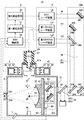
- FIG. 2 is a partial sectional view showing the configuration of the EUV light generation system 11 according to the first embodiment.
- a condensing optical system 22 a, an EUV condensing mirror 23, a target recovery unit 28, an EUV condensing mirror holder 81, and plates 82 and 83 are provided inside the chamber 2. It may be done.
- the target generation unit 26, the target sensor 4, the light emitting unit 45, and the EUV light sensor 7 may be attached to the chamber 2.
- the laser system 3, the laser light traveling direction control unit 34 a, the photodetector 35, and the EUV light generation control unit 5 may be provided outside the chamber 2.
- the EUV light generation controller 5 may include an EUV controller 50, a first delay circuit 51, and a second delay circuit 52.
- the target generation unit 26 may have a reservoir 61.
- the reservoir 61 may store the material of the melted target inside.
- the material of the target may be maintained at a temperature above its melting point by a heater (not shown) provided in the reservoir 61.
- a part of the reservoir 61 may pass through the through hole 2 a formed in the wall surface of the chamber 2, and the tip of the reservoir 61 may be located inside the chamber 2.
- An opening 62 may be formed at the tip of the reservoir 61.
- the flange portion 61a of the reservoir 61 may be fixed in close contact with the wall surface of the chamber 2 around the through hole 2a.
- the target sensor 4 and the light emitting unit 45 may be disposed on opposite sides of the trajectory of the target 27.
- Windows 21 a and 21 b may be attached to the chamber 2.
- the window 21 a may be located between the light emitting unit 45 and the trajectory of the target 27.
- the window 21 b may be located between the trajectory of the target 27 and the target sensor 4.
- the target sensor 4 may include an optical sensor 41, a focusing optical system 42, and a container 43.
- the container 43 may be fixed to the outside of the chamber 2, and the light sensor 41 and the condensing optical system 42 may be fixed in the container 43.
- the light emitting unit 45 may include a light source 46, a focusing optical system 47, and a container 48.
- the container 48 is fixed to the outside of the chamber 2, and the light source 46 and the focusing optical system 47 may be fixed in the container 48.
- the output light of the light source 46 can be condensed by the condensing optical system 47 at a position substantially on the trajectory of the target 27 between the target generation unit 26 and the plasma generation region 25.
- the target sensor 4 detects a change in light intensity of light passing through the trajectory of the target 27 and the periphery thereof, and outputs a target detection signal. Good.
- the laser system 3 may include a first YAG laser device La1, a second YAG laser device La2, and a CO 2 laser device Lb.
- a YAG laser device and a CO 2 laser device are illustrated, another laser device, for example, a laser device using Nd: YVO 4 may be used.
- the YAG laser apparatus may include a laser oscillator and, if necessary, a laser amplifier, and may use a YAG crystal as a laser medium for either or both of the laser oscillator and the laser amplifier.
- the CO 2 laser apparatus may include a laser oscillator and, if necessary, a laser amplifier, and may use CO 2 gas as a laser medium for either or both of the laser oscillator and the laser amplifier.
- the first YAG laser device La1 may output a first pre-pulse laser beam P1.
- the second YAG laser device La2 may output a second pre-pulse laser beam P2.
- the CO 2 laser device Lb may output the main pulse laser beam M.
- the laser beam direction control unit 34a may include high reflection mirrors 340, 341 and 342, and beam combiners 343 and 344.
- the high reflection mirror 340 may be supported by the holder 345.
- the high reflection mirror 341 may be supported by the holder 346.
- the high reflection mirror 342 may be supported by the holder 347.
- Beam combiner 343 may be supported by holder 348.
- the beam combiner 343 transmits the linearly polarized light whose polarization direction is parallel to the paper with high transmittance, and reflects the linearly polarized light whose polarization direction is perpendicular to the paper with high reflectance, so that the optical paths of the two lights are almost It may also include polarizers to match.
- Beam combiner 344 may be supported by holder 349.
- the beam combiner 344 transmits the light containing the first wavelength component with high transmittance, and reflects the light containing the second wavelength component with high reflectance to substantially match the optical paths of the two light It may include a dichroic mirror.
- the beam combiner 343 may also be a dichroic mirror.
- the light detector 35 may be disposed in the optical path of the pulsed laser light 32 between the laser light traveling direction control unit 34 a and the focusing optical system 22 a.
- the photodetector 35 may include a beam splitter 351 and an optical sensor 352.
- the plate 82 may be fixed to the chamber 2.
- the plate 83 may be supported by the plate 82.
- the focusing optics 22 a may include an off-axis parabolic mirror 221 and a flat mirror 222.
- the off-axis paraboloidal mirror 221 may be supported by the holder 223.
- the flat mirror 222 may be supported by the holder 224.
- the holders 223 and 224 may be fixed to the plate 83.
- the position adjustment mechanism 84 may be able to adjust the position of the plate 83 relative to the plate 82 by a control signal output from the EUV control unit 50. By adjusting the position of the plate 83, the positions of the off-axis paraboloidal mirror 221 and the plane mirror 222 may be adjusted. The positions of the off-axis paraboloidal mirror 221 and the flat mirror 222 may be adjusted such that the pulsed laser light 33 reflected by these mirrors is condensed at the plasma generation region 25.
- the EUV collector mirror 23 may be fixed to the plate 82 via the EUV collector mirror holder 81.
- the EUV light sensor 7 may receive part of the EUV light generated in the plasma generation region 25 and detect the energy of the EUV light or the light intensity of the EUV light.
- the EUV light sensor 7 may output the detection result to the EUV control unit 50.
- the EUV control unit 50 included in the EUV light generation controller 5 outputs a control signal to the target generation unit 26 so that the target generation unit 26 outputs the target 27.
- the target generation unit 26 may sequentially output a plurality of droplet-shaped targets 27 via the opening 62.
- the plurality of droplet targets 27 may reach the plasma generation region 25 according to the order of their outputs.
- the target recovery unit 28 may be disposed on an extension of the trajectory of the target 27 and may recover the target 27 that has passed through the plasma generation region 25.
- the EUV control unit 50 may receive a target detection signal output from the target sensor 4.
- the EUV control unit 50 controls the laser system 3 so that the pulsed laser light 33 is focused on the target 27 at the timing when the target 27 reaches the plasma generation region 25 or its vicinity. May be controlled.
- the EUV control unit 50 may output the first trigger signal to the first YAG laser La1 and the first delay circuit 51 based on the target detection signal.
- the first YAG laser device La1 may output the first pre-pulse laser beam P1 in accordance with the first trigger signal.
- the first delay circuit 51 may receive a first trigger signal.
- the first delay circuit 51 sends a second trigger signal indicating that the first delay time has elapsed with respect to the reception timing of the first trigger signal to the second YAG laser device La2 and the second delay circuit 52. You may output it.
- the second YAG laser device La2 may output the second pre-pulse laser beam P2 in accordance with the second trigger signal.
- the second delay circuit 52 may receive a second trigger signal.
- the second delay circuit 52 may output, to the CO 2 laser device Lb, a third trigger signal indicating that the second delay time has elapsed with respect to the reception timing of the second trigger signal.
- the EUV control unit 50 may also output the first trigger signal to the second delay circuit 52.
- the second delay circuit 52 which receives the first trigger signal, a third trigger signal indicating that the first and second delay time to the reception timing of the first trigger signal has passed, CO 2 laser It may be output to the device Lb.
- the CO 2 laser device Lb may output the main pulse laser beam M according to the third trigger signal.
- the laser system 3 may output the first prepulse laser beam P1, the second prepulse laser beam P2, and the main pulse laser beam M in this order.
- the high reflection mirror 340 included in the laser light traveling direction control unit 34a is disposed in the optical path of the first pre-pulsed laser light P1 output by the first YAG laser device La1. Good.
- the high reflection mirror 340 may reflect the first pre-pulse laser beam P1 with a high reflectance.
- the beam combiner 343 is disposed at a position where the optical path of the first pre-pulse laser beam P1 reflected by the high reflection mirror 340 intersects the optical path of the second pre-pulse laser beam P2 output by the second YAG laser device La2. May be
- the first pre-pulse laser beam P1 may be linearly polarized light whose polarization direction is parallel to the paper surface.
- the second pre-pulse laser beam P2 may be linearly polarized light whose polarization direction is perpendicular to the paper surface.
- the first pre-pulse laser beam P1 may be incident on the beam combiner 343 from the upper side in the drawing.
- the second pre-pulse laser beam P2 may be incident on the beam combiner 343 from the left side in the drawing.
- the beam combiner 343 may transmit the first pre-pulse laser beam P1 at high transmittance, reflect the second pre-pulse laser beam P2 at high reflectance, and guide the light to the beam combiner 344.
- the high reflection mirrors 341 and 342 may be disposed in the optical path of the main pulse laser beam M output by the CO 2 laser device Lb.
- the high reflection mirrors 341 and 342 may sequentially reflect the main pulse laser beam M at a high reflectance.
- the beam combiner 344 may be disposed at a position where the optical paths of the first pre-pulse laser beam P1 and the second pre-pulse laser beam P2 cross the optical path of the main pulse laser beam M reflected by the high reflection mirror 342.
- the main pulse laser beam M may include wavelength components different from the wavelength components contained in the first prepulse laser beam P1 and the second prepulse laser beam P2.
- the first pre-pulse laser beam P1 and the second pre-pulse laser beam P2 may be incident on the beam combiner 344 from the upper side in the drawing.
- the main pulse laser beam M may be incident on the beam combiner 344 from the right side in the drawing.
- the beam combiner 344 reflects the first pre-pulse laser beam P1 and the second pre-pulse laser beam P2 with a high reflectance, transmits the main pulse laser beam M with a high transmittance, and collects these lights as a pulse laser beam 32. It may be led to the optical system 22a.
- the beam splitter 351 included in the light detector 35 transmits the pulsed laser light 32 toward the focusing optical system 22a with high transmittance and a part of the pulsed laser light 32. May be reflected toward the light sensor 352.
- the optical sensor 352 may receive part of the pulsed laser light 32 reflected by the beam splitter 351 and output a laser light reception signal indicating the light reception timing and other parameters thereof to the EUV control unit 50.
- the timing at which the pulse laser light 32 is received by the light sensor 352 may be substantially the same as the timing at which the pulse laser light 33 is irradiated to the target 27.
- FIG. 3 is a waveform diagram showing an example of a laser reception signal in the first embodiment.
- the horizontal axis may indicate time t
- the vertical axis may indicate light intensity I.
- the pulse laser beam 32 received by the optical sensor 352 may include the first prepulse laser beam P1, the second prepulse laser beam P2, and the main pulse laser beam M.
- the first prepulse laser beam P1, the second prepulse laser beam P2, and the main pulse laser beam M may be incident on the light sensor 352 in this order.
- the pulse energy of the main pulse laser beam M may be larger than the pulse energy of the first prepulse laser beam P1 and the second prepulse laser beam P2.
- the pulse energy can be estimated by integrating the light intensity I.
- the off-axis paraboloidal mirror 221 included in the focusing optical system 22 a may be disposed in the optical path of the pulsed laser beam 32.
- the off-axis paraboloidal mirror 221 may reflect the pulsed laser light 32 toward the plane mirror 222.
- the flat mirror 222 may reflect the pulse laser beam 32 reflected by the off-axis paraboloidal mirror 221 as the pulse laser beam 33 toward the plasma generation region 25 or in the vicinity thereof.
- the pulsed laser light 33 may be condensed at or near the plasma generation region 25 in accordance with the shape of the reflection surface of the off-axis paraboloidal mirror 221.
- the first pre-pulse laser beam P1, the second pre-pulse laser beam P2, and the main pulse laser beam M may be applied to one target 27 in this order in the plasma generation region 25 or in the vicinity thereof.
- the droplet-like target 27 is irradiated with the first pre-pulse laser beam P1
- the droplet-like target 27 is broken into a plurality of fine particles and diffused, whereby a secondary target can be generated.
- the second target may be irradiated with the second pre-pulsed laser beam P2 to generate a third target including at least vapor or pre-plasma.
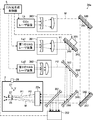
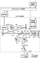
- FIG. 4 schematically illustrates a first configuration example of the laser light traveling direction control unit 34 a and the periphery thereof in the EUV light generation system 11 illustrated in FIG. 2.
- the components such as the EUV collector mirror 23 and the target sensor 4 incidental to the chamber 2 are not shown.
- the specific configuration of the focusing optical system 22a and the target generation unit 26 is also omitted.
- the target 27 can move in the arrow Y direction from the irradiation timing of the first pre-pulse laser light P1 to the target 27 to the irradiation timing of the second pre-pulse laser light P2. .
- the moving distance may be long.
- the optical path axis of the first pre-pulse laser beam P1 may substantially intersect the trajectory of the target 27 upstream of the plasma generation region 25 in the moving direction of the target 27.
- the optical path axis of the second pre-pulse laser beam P2 and the optical path axis of the main pulse laser beam M may pass through the plasma generation region 25.
- the velocity of the target 27 when the target 27 reaches the vicinity of the plasma generation region 25 may be, for example, 100 m / s.
- the delay time from the irradiation timing of the first pre-pulse laser beam P1 to the target 27 to the irradiation timing of the second pre-pulse laser beam P2 may be, for example, 2.0 ⁇ s.
- the optical path axis of the first pre-pulse laser beam P1 may intersect the trajectory of the target 27 at a position shifted 200 ⁇ m upstream of the plasma generation region 25 in the moving direction of the target 27.
- the high reflection mirror 340 is disposed at a position different from the optical path of the second pre-pulse laser beam P2 and the optical path of the main pulse laser beam M in the optical path of the first pre-pulse laser beam P1.
- An actuator 365 may be attached to the holder 345 of the high reflection mirror 340, and the EUV light generation controller 5 may control the actuator 365 to adjust the attitude of the high reflection mirror 340.
- the traveling direction of the first pre-pulse laser beam P1 may be controlled such that the first pre-pulse laser beam P1 intersects the trajectory of the target at a desired position near the plasma generation region 25.
- the attitude of the high reflection mirror 340 is It may be further adjusted.
- FIG. 4 describes the case where the actuator is attached to the high reflection mirror 340, the present disclosure is not limited thereto.
- An actuator may be attached to a high reflection mirror (not shown) disposed in the optical path of the high reflection mirror 341 or the second pre-pulse laser beam P2.
- the focusing diameter of the first pre-pulse laser beam P1 may be substantially equal to the diameter of the target 27 or slightly larger than the diameter of the target 27.
- the condensed diameter of the second pre-pulse laser beam P2 is substantially equal to or slightly larger than the dispersion diameter of the target 27 diffused by the irradiation of the first pre-pulse laser beam P1. It is also good.
- the focusing diameter of the main pulse laser beam M may be substantially equal to the focusing diameter of the second pre-pulse laser beam P2. Therefore, preferably, the focusing diameter of the first pre-pulse laser beam P1 may be smaller than the focusing diameter of the second pre-pulse laser beam P2 and the focusing diameter of the main pulse laser beam M.
- the pulse laser beam is a plane wave and the pulse laser beam is focused on the target at the beam waist position of the pulse laser beam focused by the focusing optical system 22a.
- the condensed diameter D of the beam waist can be expressed by the following approximate expression.
- F may be the focal length of the focusing optical system
- ⁇ may be the wavelength of the laser light.
- M 2 is a value indicating how close the beam is to the single mode transverse mode beam, and may be a value indicating how small the beam waist can be focused.
- B may be the beam diameter of the laser beam incident on the focusing optical system.
- the focused diameter D of the laser light may be proportional to the wavelength ⁇ of the laser light and inversely proportional to the beam diameter B of the laser light.
- the first pre-pulse laser beam P1 may have a wavelength shorter than the wavelength of the main pulse laser beam M.
- the focusing diameter of the first pre-pulse laser beam P1 is the same as the main pulse laser beam M. It can be smaller than the focusing diameter of The first pre-pulse laser beam P1 may have a beam diameter larger than the beam diameter of the second pre-pulse laser beam P2.
- the focusing diameter of the first pre-pulse laser beam P1 is the second pre-pulse laser beam P2. It can be smaller than the focusing diameter of
- a pulsed laser beam with a wavelength of 1.06 ⁇ m output from the first YAG laser device La1 may be used as the first pre-pulse laser beam P1.
- a pulsed laser beam having a wavelength of 1.06 ⁇ m, which is output from the second YAG laser device La2 may be used.
- the main pulse laser light M pulsed laser light having a wavelength of 10.6 ⁇ m, which is output from the CO 2 laser device Lb, may be used.
- the first beam expander 361 is an optical path of the first pre-pulse laser beam P1, which is different from the optical path of the second pre-pulse laser beam P2 and the optical path of the main pulse laser beam M. It may be arranged at a position.
- the second beam expander 362 may be disposed at a position different from the optical path of the first pre-pulse laser beam P1 and the optical path of the main pulse laser beam M in the optical path of the second pre-pulse laser beam P2.
- the third beam expander 363 may be disposed at a position different from the optical path of the first pre-pulse laser beam P1 and the optical path of the second pre-pulse laser beam P2 in the optical path of the main pulse laser beam M.
- the first beam expander 361, the second beam expander 362, and the third beam expander 363 may each include a spherical concave lens and a spherical convex lens.
- the third beam expander 363 may include a spherical concave mirror and a spherical convex mirror to withstand high thermal loads.
- the first to third beam expanders 361 to 363 are configured such that the beam diameter of the first pre-pulse laser beam P1 and the beam diameter of the main pulse laser beam M are larger than the beam diameter of the second pre-pulse laser beam P2. In each case, the beam diameter may be controlled.
- the focusing diameter of the first pre-pulse laser beam P1 can be made smaller than the focusing diameter of the second pre-pulse laser beam P2 and the focusing diameter of the main pulse laser beam M.
- the focal length F of the focusing optical system 22a is 200 mm.
- the value of M 2 for each of the first pre-pulse laser beam P 1, the second pre-pulse laser beam P 2, and the main pulse laser beam M is assumed to be 1.
- the beam diameter B for obtaining the desired focused diameter D can be calculated as follows using the above-mentioned approximate expression.
- the beam diameter B of the first pre-pulse laser beam P1 incident on the focusing optical system 22a is approximately 3 in order to set the focusing diameter D to 70 ⁇ m. It can be calculated as .9 mm.
- the beam diameter B of the second pre-pulse laser beam P2 incident on the focusing optical system 22a is about 0 to set the focusing diameter D to 300 ⁇ m. It can be calculated as .9 mm.
- the beam diameter B of the main pulse laser beam M incident on the focusing optical system 22 a is about 9.0 mm in order to set the focusing diameter D to 300 ⁇ m. It can be calculated as
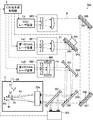
- FIG. 5 schematically shows a second configuration example of the laser light traveling direction control unit 34 a and its periphery in the EUV light generation system 11 shown in FIG. 2.
- the components such as the EUV collector mirror 23 and the target sensor 4 incidental to the chamber 2 are not shown.
- the specific configuration of the focusing optical system 22a and the target generation unit 26 is also omitted.
- the configuration example shown in FIG. 5 is the configuration example shown in FIG. 4 in that the second beam expander 362 is provided with an actuator 366 in order to adjust the wavefront and beam diameter of the second pre-pulse laser beam P2. It is different from The other points are the same as those of the configuration example shown in FIG.
- the actuator 366 shown in FIG. 5 may be attached to a spherical convex lens included in the second beam expander 362.
- the distance between the spherical convex lens and the spherical concave lens included in the second beam expander 362 may be increased or decreased by controlling the actuator 366 by the EUV light generation controller 5.
- the wavefront of the second pre-pulse laser beam P2 can be made a wavefront having a curvature other than a plane wave, and the distance from the focusing optical system 22a to the beam waist position of the second pre-pulse laser beam P2 can be changed.
- FIG. 5 shows an example in which the second pre-pulse laser beam P2 output from the second beam expander 362 is a wave having a wave front whose front side in the traveling direction is convex, that is, a convex wave. .
- the distance from the focusing optical system 22a to the beam waist position of the second pre-pulse laser beam P2 may be longer than the focal length of the focusing optical system 22a.
- the beam diameter of the second pre-pulse laser beam P2 at the position where it is incident on the condensing optical system 22a is larger than the beam diameter of the second pre-pulse laser beam P2 in FIG.
- the beam diameter of the second pre-pulse laser beam P2 in the plasma generation region 25 can be adjusted by adjusting the wavefront and the beam diameter of the second pre-pulse laser beam P2.
- FIG. 5 describes the case where the actuator is attached to the second beam expander 362, the present disclosure is not limited thereto.
- An actuator may be attached to the first beam expander 361 or the third beam expander 363.
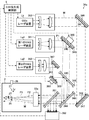
- FIG. 6 schematically shows a third example of the configuration of the laser light traveling direction control unit 34a and its periphery in the EUV light generation system 11 shown in FIG.
- the components such as the EUV collector mirror 23 and the target sensor 4 incidental to the chamber 2 are not shown.
- the specific configuration of the focusing optical system 22a and the target generation unit 26 is also omitted.
- the configuration example shown in FIG. 6 is an example configuration shown in FIG. 4 in that an optical path adjustment unit including high reflection mirrors 367 and 368 and an actuator 369 attached to a holder of high reflection mirror 368 is provided. It is different from The other points are the same as those of the configuration example shown in FIG.
- the optical path adjustment unit may be provided at a position different from the optical path of the first prepulse laser beam P1 and the optical path of the main pulse laser beam M in the optical path of the second prepulse laser beam P2.
- the high reflection mirror 367 may be disposed in the optical path of the second pre-pulse laser beam P2 between the second beam expander 362 and the beam combiner 343.
- the high reflection mirror 367 may reflect the second pre-pulse laser beam P2 at a high reflectance.
- the high reflection mirror 368 may be disposed in the optical path of the second pre-pulse laser beam P2 between the high reflection mirror 367 and the beam combiner 343.
- the high reflection mirror 368 may reflect the second prepulse laser beam P2 toward the beam combiner 343 with a high reflectance.
- the posture of the high reflection mirror 368 may be adjusted by the EUV light generation controller 5 controlling the actuator 369. Thereby, the traveling direction of the second pre-pulse laser beam P2 may be controlled.
- the optical path axis of the second pre-pulse laser beam P2 intersects the path of the target 27 at a position between the position where the optical path axis of the first pre-pulse laser beam P1 intersects with the path of the target 27 and the plasma generation region 25 It is also good.
- FIG. 7 is a partial cross-sectional view showing a configuration of an EUV light generation system 11 according to a second embodiment.
- the second embodiment shown in FIG. 7 differs from the first embodiment shown in FIG. 2 in that the laser system 3 comprises one YAG laser device La and one CO 2 laser device Lb. .
- the second trigger signal from the first delay circuit 51 and the third trigger signal from the second delay circuit 52 are input to the CO 2 laser device Lb. It differs from the first embodiment.
- the beam combiner 343 in the first embodiment may not be present.
- the EUV control unit 50 may output the first trigger signal to the YAG laser device La and the first delay circuit 51 based on the target detection signal.
- the YAG laser device La may output the first pre-pulse laser beam P1 in accordance with the first trigger signal.
- the first delay circuit 51 may receive a first trigger signal.
- the first delay circuit 51 outputs a second trigger signal indicating that the first delay time has elapsed with respect to the reception timing of the first trigger signal to the CO 2 laser device Lb and the second delay circuit 52. May be
- the CO 2 laser apparatus Lb may output the second pre-pulse laser beam P2 in accordance with the second trigger signal.
- the second delay circuit 52 may receive a second trigger signal.
- the second delay circuit 52 may output, to the CO 2 laser device Lb, a third trigger signal indicating that the second delay time has elapsed with respect to the reception timing of the second trigger signal.
- the EUV control unit 50 may also output the first trigger signal to the second delay circuit 52.
- the second delay circuit 52 which receives the first trigger signal, a third trigger signal indicating that the first and second delay time to the reception timing of the first trigger signal has passed, CO 2 laser It may be output to the device Lb.
- the CO 2 laser device Lb may output the main pulse laser beam M according to the third trigger signal.
- the laser system 3 may output the first prepulse laser beam P1, the second prepulse laser beam P2, and the main pulse laser beam M in this order.
- FIG. 8 is a waveform diagram showing an example of a laser reception signal in the second embodiment.
- the horizontal axis may indicate time t, and the vertical axis may indicate light intensity I.
- the pulse laser beam 32 received by the optical sensor 352 may include the first prepulse laser beam P1, the second prepulse laser beam P2, and the main pulse laser beam M.
- the first prepulse laser beam P1, the second prepulse laser beam P2, and the main pulse laser beam M may be incident on the light sensor 352 in this order.
- the pulse energy of the main pulse laser beam M may be larger than the pulse energy of the first prepulse laser beam P1 and the second prepulse laser beam P2.
- FIG. 9 schematically illustrates an example of the configuration of the laser light traveling direction control unit 34 a and the periphery thereof in the EUV light generation system 11 illustrated in FIG. 7.
- the components such as the EUV collector mirror 23 and the target sensor 4 incidental to the chamber 2 are not shown.
- the specific configuration of the focusing optical system 22a and the target generation unit 26 is also omitted.
- the first pre-pulse laser beam P1 output from the YAG laser device La may be reflected by the high reflection mirror 340 and the beam combiner 344 to be incident on the focusing optical system 22a.
- the second pre-pulse laser beam P2 and the main pulse laser beam M output from the CO 2 laser device Lb may be reflected by the high reflection mirrors 341 and 342 and may be incident on the focusing optical system 22a.
- the main pulse laser is from the irradiation timing of the second pre-pulse laser beam P2.
- the time to the irradiation timing of the light M may be short. Therefore, the change in the movement distance of the target and the diffusion diameter of the target from the irradiation timing of the second pre-pulse laser beam P2 to the target 27 to the irradiation timing of the main pulse laser beam M may be small.
- the second pre-pulse laser beam P2 and the main pulse laser beam M may have approximately the same wavelength and approximately the same beam diameter.
- the second pre-pulse laser beam P2 and the main pulse laser beam M can be focused to substantially the same focusing diameter by the focusing optical system 22a.
- the optical path axis of the second pre-pulse laser beam P2 and the optical path axis of the main pulse laser beam M from the focusing optical system 22a to the plasma generation region 25 may be substantially the same.
- the other points may be the same as in the first embodiment.
- FIG. 10 is a waveform diagram showing another example of the laser light reception signal in the second embodiment.
- the horizontal axis may indicate time t, and the vertical axis may indicate light intensity I.
- the pulsed laser light 32 received by the light sensor 352 may include the pre-pulsed laser light P and the main pulsed laser light MP.
- the pre-pulse laser beam P and the main pulse laser beam MP may be incident on the optical sensor 352 in this order.
- the pulse energy of the main pulse laser beam MP may be larger than the pulse energy of the pre-pulse laser beam P.
- the pre-pulse laser beam P may be output from the YAG laser device La, like the first pre-pulse laser beam P1 shown in FIG.
- the main pulse laser beam MP may be output from the CO 2 laser device Lb.
- the second pre-pulse laser beam P2 shown in FIG. 8 may not be output.
- the pulse waveform of the main pulse laser beam MP shown in FIG. 10 has a low light intensity and gradually increases a first step M1 and a second step M2 in which the light intensity sharply increases after the first step M1; After the second step M2, a third step M3 in which the light intensity decreases may be included. That is, the increase rate of the light intensity in the second stage M2 may be larger than the increase rate of the light intensity in the first stage M1.
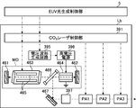
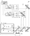
- FIG. 11A schematically shows a first configuration example of the CO 2 laser device Lb in the second embodiment.
- the CO 2 laser apparatus Lb according to the second embodiment includes first and second master oscillators MO1 and MO2, a CO 2 laser control unit 391, a beam combiner 399, and first to third amplifiers PA1 to PA3. May be included.
- the first master oscillator MO1 may output the first seed laser light according to the second trigger signal output from the CO 2 laser control unit 391.
- the second master oscillator MO2 may output the second seed laser light according to the third trigger signal output from the CO 2 laser control unit 391.
- the beam combiner 399 may combine the optical paths of the seed laser beams output from the first and second master oscillators MO1 and MO2, respectively, and may output them toward the first amplifier PA1.
- the beam combiner 399 may be configured by a half mirror or a grating.
- a beam splitter not shown may be disposed in the optical path between the amplifiers (between PA1 and PA2 or PA2 and PA3). In that case, the beam splitter combines the pulsed laser light output from the first master oscillator MO1 and the pulsed laser light output from the second master oscillator MO2 and having passed at least the first amplifier PA1. May be
- FIG. 11B is a graph showing a first example of the pulse waveform of the first seed laser beam output from the first master oscillator MO1.
- FIG. 11C is a graph showing a first example of the pulse waveform of the second seed laser beam output from the second master oscillator MO2.
- the first seed laser beam output from the first master oscillator MO1 may have a smaller peak intensity than the second seed laser beam output from the second master oscillator MO2.
- the second seed laser beam output from the second master oscillator MO2 may have a constant delay time with respect to the first seed laser beam output from the first master oscillator MO1.
- FIG. 11D is a graph showing a first example of a pulse waveform of pulsed laser light output from the beam combiner 399.
- FIG. 11E is a graph showing a first example of a pulse waveform of pulse laser light output from the CO 2 laser device Lb.
- FIG. 11F is a graph showing a second example of the pulse waveform of the first seed laser beam output from the first master oscillator MO1.
- FIG. 11G is a graph showing a second example of the pulse waveform of the second seed laser beam output from the second master oscillator MO2.
- the pulse waveforms shown in FIGS. 11F and 11G may be similar to the pulse waveforms shown in FIGS. 11B and 11C, respectively.
- the time difference between the second seed laser beam output from the second master oscillator MO2 and the first seed laser beam output from the first master oscillator MO1 is the same as FIG. 11B. And may be smaller than the time difference in FIG. 11C.
- the first seed laser light output from the first master oscillator MO1 shown in FIG. 11F has a pulse waveform having a pulse width longer than that of the first seed laser light shown in FIG. 11B. It is also good.
- FIG. 11H is a graph showing a second example of the pulse waveform of pulse laser light output from the beam combiner 399.
- FIG. 11I is a graph showing a second example of the pulse waveform of pulse laser light output from the CO 2 laser device Lb.
- FIG. 12A schematically shows a second configuration example of the CO 2 laser device Lb in the second embodiment.
- the CO 2 laser apparatus Lb in the second configuration example may include a waveform adjuster 392, a beam splitter 394, a pulse waveform detector 393, and a voltage waveform control circuit 382.
- the waveform adjuster 392 may be disposed in the optical path of the pulsed laser light between the master oscillator MO and the amplifier PA1.
- the beam splitter 394 may be disposed in the optical path of the pulsed laser light output from the amplifier PA3.
- the pulse waveform detector 393 may be disposed in one of two light paths branched by the beam splitter 394.
- the pulse waveform detector 393 may detect the waveform of the pulse laser beam output from the third amplifier PA3 and output the detection result to the CO 2 laser control unit 391 for feedback control.
- FIG. 12B is a graph showing a first example of a pulse waveform of pulsed laser light output from the master oscillator MO.
- FIG. 12C is a graph showing a first example of the voltage waveform output from the voltage waveform control circuit 382.
- FIG. 12D is a graph showing a first example of the pulse waveform of the pulsed laser light output from the waveform adjuster 392.
- FIG. 12E is a graph showing a first example of a pulse waveform of pulsed laser light output from the third amplifier PA3.
- the master oscillator MO may output pulsed laser light in accordance with the second trigger signal output from the CO 2 laser control unit 391.
- the pulse waveform of the pulse laser beam output from the master oscillator MO is the time from the start of the pulse waveform of the second pre-pulse laser beam P2 to the end of the pulse waveform of the main pulse laser beam M. It may be a pulse waveform of a length including.
- the voltage waveform control circuit 382 may generate a voltage waveform as shown in FIG. 12C according to the second and third trigger signals output from the CO 2 laser control unit 391.
- the voltage waveform shown in FIG. 12C may have first and second peaks corresponding to the timings of the second and third trigger signals, respectively.
- the waveform adjuster 392 may adjust the pulse waveform of the pulsed laser light output from the master oscillator MO.
- the waveform controller 392 outputs pulse laser light having a pulse waveform shown in FIG. 12D when pulse laser light having a pulse waveform shown in FIG. 12B and a voltage waveform shown in FIG. 12C are input. It is also good.
- the second pre-pulse laser beam P2 output first and the main pulse laser beam M output after the second pre-pulse laser beam P2 are output from the CO 2 laser device Lb. It is also good.
- FIG. 12F is a graph showing a second example of the pulse waveform of pulse laser light output from the master oscillator MO.
- FIG. 12G is a graph showing a second example of the voltage waveform output from the voltage waveform control circuit 382.
- FIG. 12H is a graph showing a second example of the pulse waveform of the pulsed laser light output from the waveform adjuster 392.
- FIG. 12I is a graph showing a second example of the pulse waveform of pulsed laser light output from the third amplifier PA3.
- the pulse waveform of the pulse laser light output from the master oscillator MO has a length including the time from the start of the first step to the end of the third step of the main pulse laser light MP. It may be a pulse waveform.
- the voltage waveform shown in FIG. 12G may be a waveform having a relatively low voltage value in the first half and a relatively high voltage value in the second half.
- the timing to shift from the first half to the second half of the voltage waveform may be adjusted to the timing when the third trigger signal is input to the voltage waveform control circuit 382.
- the waveform adjuster 392 may adjust the pulse waveform of the pulsed laser light output from the master oscillator MO.
- the waveform controller 392 outputs pulse laser light having a pulse waveform shown in FIG. 12H when pulse laser light having a pulse waveform shown in FIG. 12F and a voltage waveform shown in FIG. 12G are input. It is also good.
- the main pulse laser beam MP including the third step in which the light intensity decreases may be output from the CO 2 laser device Lb.
- FIG. 13 schematically shows a configuration example of the CO 2 laser device Lb shown in FIG. 12A.
- the beam splitter 394 and the pulse waveform detector 393 are not shown.
- the waveform adjuster 392 shown in FIG. 12A may include a high voltage power supply 383, a Pockels cell 384, and a polarizer 386.
- the Pockels cell 384 may include a pair of electrodes 385 provided opposite to each other across the electro-optic crystal.
- the pulsed laser light output from the master oscillator MO may be linearly polarized in the direction perpendicular to the paper surface.
- the pulsed laser light output from the master oscillator MO may pass through the electro-optic crystal between the pair of electrodes 385.
- the Pockels cell 384 can rotate the polarization plane of the pulse laser light by 90 degrees and transmit it.
- no voltage is applied between the pair of electrodes 385, the Pockels cell 384 can transmit the pulsed laser light without rotating the polarization plane.
- the polarizer 386 may transmit pulse laser light linearly polarized in a direction parallel to the drawing sheet toward the amplifier PA1 with high transmittance.
- the polarizer 386 may reflect pulse laser light linearly polarized in the direction perpendicular to the paper surface toward the laser damper (not shown) with high reflectance.
- the CO 2 laser control unit 391 may output a second trigger signal to the master oscillator MO and may output a third trigger signal to the voltage waveform control circuit 382.
- the master oscillator MO may output pulsed laser light in response to the second trigger signal output from the CO 2 laser control unit 391.
- the voltage waveform control circuit 382 may generate a voltage waveform according to the third trigger signal output from the CO 2 laser control unit 391 and supply the voltage waveform to the high voltage power supply 383. This voltage waveform may be as shown in FIG. 12C or FIG. 12G.
- the high voltage power supply 383 may generate a pulsed voltage based on this voltage waveform and apply this voltage between the pair of electrodes 385 of the Pockels cell 384.
- the polarization component of the pulsed laser light transmitted through the Pockels cell 384 may change according to the voltage.
- the waveform of the pulsed laser light output from the waveform adjuster 392 can be adjusted by the voltage waveform generated by the voltage waveform control circuit 382.
- FIG. 14 schematically shows a third configuration example of the CO 2 laser device Lb in the second embodiment.
- the CO 2 laser device Lb in the third configuration example may include a high reflection mirror 467 and a saturable absorber cell 397 between the master oscillator MO and the amplifier PA1.
- the CO 2 laser device Lb may include a voltage waveform generation circuit 395 and a high voltage power supply 396.
- the laser chamber 463, the polarizer 466, and the Pockels cell 464 are arranged in this order from the high reflection mirror 461 side between the high reflection mirrors 461 and 462
- An optical resonator may be included.
- a pair of electrodes 465 may be disposed in the laser chamber 463 and a CO 2 gas may be accommodated as a laser medium.
- the master oscillator MO excites the laser medium in the laser chamber 463 by a discharge generated between the pair of electrodes 465, and amplifies the laser light by reciprocating the laser light between the high reflection mirrors 461 and 462 It is also good.
- the laser beam reciprocating between the high reflection mirrors 461 and 462 may be linearly polarized in the direction parallel to the paper surface.
- the polarizer 466 may transmit laser light linearly polarized in a direction parallel to the paper surface with high transmittance.
- the Pockels cell 464 may include an electro-optic crystal (not shown) and a pair of electrodes (not shown).
- the high voltage power supply 396 may output a pulsed voltage based on the voltage waveform generated by the voltage waveform generation circuit 395.
- the pulse-like voltage output from the high voltage power supply 396 may be applied to the pair of electrodes of the Pockels cell 464.
- the Pockels cell 464 may shift the phase of the orthogonal polarization component of the incident laser light by 1 ⁇ 4 wavelength and transmit it.
- the laser light transmitted through the Pockels cell 464 from the left to the right in the drawing and reflected by the high reflection mirror 462 and transmitted through the Pockels cell 464 from the right to the left in the drawing has a total of 1/0 the phases of the orthogonal polarization components. It may be shifted by two wavelengths. Then, this laser beam may be incident on the polarizer 466 as a laser beam linearly polarized in a direction perpendicular to the paper surface. The polarizer 466 may output this laser beam from the master oscillator MO by reflecting the linearly polarized laser beam in the direction perpendicular to the paper surface.
- the waveform of the pulsed voltage applied to the Pockels cell 464 by the high voltage power supply 396 may be similar to the waveform of the voltage shown in FIG. 12G.
- the pulse waveform of the pulse laser light reflected by the polarizer 466 has a low light intensity, and the light intensity steeply increases after the first step when the rate of increase of the light intensity gradually increases is small. It may include a second stage of increasing to reach a peak value and a third stage of decreasing light intensity after the second stage.
- the high reflection mirror 467 may be disposed in the optical path of the pulsed laser light reflected by the polarizer 466 and may reflect the pulsed laser light toward the saturable absorber cell 397 with a high reflectance.
- the saturable absorber cell 397 may contain, for example, a gaseous saturable absorber therein.
- the saturable absorber cell 397 absorbs much of the incident light for incident light having a light intensity less than a predetermined value, and transmits most of the incident light for incident light having a light intensity greater than or equal to the predetermined value.
- the saturable absorber cell used for CO 2 laser light may be a gas cell containing SF 6 gas.
- the other points may be the same as the second configuration example described using FIG. 12A.
- FIGS. 15 and 16 show the first and second embodiments. It is a graph which shows the measurement result of CE in EUV light generation system 11 concerning a.
- the horizontal axis may indicate the fluence of the second pre-pulse laser beam P2 or the fluence at the first stage of the main pulse laser beam MP, and the vertical axis may indicate CE.
- the horizontal axis may indicate the light intensity per unit area of the second pre-pulse laser beam P2 or the light intensity per unit area in the first step of the main pulse laser beam MP, and the vertical axis may indicate CE.
- the measurement of CE was performed under the following conditions.
- the diameter of the target 27 was in the range of 21 ⁇ m to 22 ⁇ m.
- the following two types of light were used as the first pre-pulse laser beam P1.
- a pulsed laser beam with a wavelength of 1.06 ⁇ m by a Nd: YAG (neodymium-doped yttrium aluminum garnet) laser device was used as the first pre-pulse laser beam P1.
- the pulse width according to the full width at half maximum of this pulse laser light was 10 ns, and the pulse energy was in the range of 0 mJ to 2.7 mJ.
- Nd a mode-locked laser device using a YVO 4 as a master oscillator
- Nd Wavelength 1 which is amplified by the reproduction amplifier using YAG.
- a 06 ⁇ m pulse laser beam was used.
- the pulse width according to the full width at half maximum of this pulse laser light was 14 ps, and the pulse energy was in the range of 0 mJ to 2.0 mJ.
- the focusing diameter of the first pre-pulse laser beam P1 is 70 ⁇ m when represented by the diameter of a portion having a light intensity of 1 / e 2 or more of the peak intensity at the focusing position.
- the target 27 was irradiated with the second prepulse laser beam P2 and the main pulse laser beam M next to the first prepulse laser beam P1.
- the set value of the energy of the second prepulse laser beam P2 was changed between 0 mJ and 2.4 mJ.
- the CE was measured while changing the irradiation timing of the second pre-pulse laser beam P2, and the highest CE is shown in FIGS. 15 and 16 for each set value of the energy of the second pre-pulse laser beam P2.
- the target 27 is irradiated with the main pulse laser beam MP having the first to third steps.
- the time width of the first step of the main pulse laser beam MP was about 50 ns, and the energy in the first step was changed between 0 mJ and 80 mJ to measure CE.
- the second pre-pulse laser beam P2 a pulsed laser beam with a wavelength of 1.06 ⁇ m by a Nd: YAG laser device was used.
- the pulse width by the full width at half maximum of this pulse laser light was 5 ns.
- the focusing diameter of the second pre-pulse laser beam P2 is 400 ⁇ m when represented by the diameter of a portion having a light intensity of 1 / e 2 or more of the peak intensity at the irradiation position on the target.
- the main pulse laser beam M or the main pulse laser beam MP a pulse laser beam with a wavelength of 10.6 ⁇ m by a CO 2 laser device was used.
- the pulse width based on the full width at half maximum of this pulse laser light was 15 ns, and the pulse energy was in the range of 20 mJ to 170 mJ.
- the focusing diameter of the main pulse laser beam M is 300 ⁇ m when represented by the diameter of a portion having a light intensity of 1 / e 2 or more of the peak intensity at the irradiation position on the target.
- the pulse width at full width at half maximum of pulse laser light Td
- the CE is better than when the fluence of the second pre-pulse laser beam P2 is 0 J / cm 2 was high.
- the main pulse laser beam MP does not include the first step, that is, when the main pulse laser beam MP includes the first step than when the fluence in the first step is 0 J / cm 2 , CE was high.
- Fluence of the second pre-pulse laser beam P2 is, 1.0 J / cm 2 or more, preferably may be 1.5 J / cm 2 or more, may be less fluence of the main pulse laser beam M.
- the CE improves.
- the fluence in the first stage of the main pulse laser beam MP may be 2 J / cm 2 or more, preferably 5 J / cm 2 or more, or may be less than or equal to the sum of the fluences in the second and third stages of the main pulse laser beam MP. .
- the light intensity per unit area of the second pre-pulse laser beam P2 may be 0.4 ⁇ 10 8 W / cm 2 or more, preferably 3.0 ⁇ 10 8 W / cm 2 or more, and the unit of the main pulse laser beam M It may be less than the light intensity per area.
- the light intensity per unit area in the first step of the main pulse laser beam MP may be 0.4 ⁇ 10 8 W / cm 2 or more, preferably 1.7 ⁇ 10 8 W / cm 2 or more, and the main pulse It may be less than the light intensity per unit area in the second and third stages of the laser beam MP.
- FIGS. 17 and 18 are other graphs showing the measurement results of CE in the EUV light generation system 11 according to the first embodiment.
- the horizontal axis may indicate the irradiation timing of the second pre-pulse laser beam P2
- the vertical axis may indicate CE.
- the irradiation timing of the main pulse laser beam M is 0, the irradiation timing of the second pre-pulse laser beam P2 may be a time traced back from the irradiation timing of the main pulse laser beam M.
- the target 27, the irradiation condition of the second pre-pulse laser beam P2 and the irradiation condition of the main pulse laser beam M were the same as those described with reference to FIGS. Then, CE was measured while changing the irradiation timing of the second pre-pulse laser beam P2 in the range of ⁇ 0.6 ⁇ s to 0 ⁇ s for each setting value of the energy of the second pre-pulse laser beam P2.
- the result of using the first pre-pulse laser beam P1 having a pulse width on the picosecond order under the measurement conditions described with reference to FIG. 15 and FIG. 16 is shown in FIG.
- the fluence of the first pre-pulse laser beam P1 was 5.2 J / cm 2 .
- the irradiation timing of the first pre-pulse laser beam P1 is set to a timing of -1.1 ⁇ s going back from the irradiation timing of the main pulse laser beam M when the irradiation timing of the main pulse laser beam M is 0.
- the result of using the first pre-pulse laser beam P1 having a nanosecond pulse width under the measurement conditions described with reference to FIGS. 15 and 16 is shown in FIG.
- the fluence of the first pre-pulse laser beam P1 was 7.0 J / cm 2 .
- the irradiation timing of the first pre-pulse laser beam P1 is set to a timing of -2.7 ⁇ s going back from the irradiation timing of the main pulse laser beam M when the irradiation timing of the main pulse laser beam M is 0.
- the irradiation timing of the second pre-pulse laser beam P2 is preferably -0.37 ⁇ s, where the irradiation timing of the main pulse laser beam M is 0. It may be in the range of ⁇ 0.03 ⁇ s. More preferably, it may be in the range of ⁇ 0.22 ⁇ s to ⁇ 0.07 ⁇ s.
- the irradiation timing of the second pre-pulse laser beam P2 is preferably -0.57 ⁇ s, where the irradiation timing of the main pulse laser beam M is 0. It may be in the range of ⁇ 0.03 ⁇ s.
- FIGS. 19 and 20 are still another graphs showing the measurement results of CE in the EUV light generation system 11 according to the first and second embodiments.
- the horizontal axis may indicate the fluence of the main pulse laser beam M or MP
- the vertical axis may indicate CE.
- the target 27, irradiation conditions of the second pre-pulse laser beam P2, irradiation conditions of the main pulse laser beam M, and irradiation conditions of the main pulse laser beam MP having the first to third steps are described with reference to FIGS. It was the same as However, the fluence of the second pre-pulse laser beam P2 and 1.6 J / cm 2, the set value of the fluence of the main pulse laser beam M, was measured CE while changing between 20J / cm 2 ⁇ 200J / cm 2 .
- the fluence of the first stage of the main pulse laser beam MP and 34 J / cm 2 the total value of the fluence in the second stage and third stage of the main pulse laser beam MP, of 20J / cm 2 ⁇ 200J / cm 2 CE was measured while changing between.
- the result of using the first pre-pulse laser beam P1 having a pulse width on the order of picoseconds under the measurement conditions described with reference to FIGS. 15 and 16 is shown in FIG.
- the fluence of the first pre-pulse laser beam P1 was 5.2 J / cm 2 .
- the irradiation timing of the first pre-pulse laser beam P1 is set to a timing of -1.1 ⁇ s going back from the irradiation timing of the main pulse laser beam M when the irradiation timing of the main pulse laser beam M is 0.
- the result of using the first pre-pulse laser beam P1 having a pulse width on the nanosecond order under the measurement conditions described with reference to FIGS. 15 and 16 is shown in FIG.
- the fluence of the first pre-pulse laser beam P1 was 7.0 J / cm 2 .
- the irradiation timing of the first pre-pulse laser beam P1 is set to a timing of -2.7 ⁇ s going back from the irradiation timing of the main pulse laser beam M when the irradiation timing of the main pulse laser beam M is 0.
- the following can be understood.
- the measurement is constant over the entire fluence measurement range of the main pulse laser beam M.
- the CE of was obtained.
- the main pulse laser beam MP is irradiated when the first pre-pulse laser beam P1 has a pulse width on the order of nanoseconds, the fluence measurement range in the second and third stages of the main pulse laser beam MP can be obtained. A constant CE was obtained.
- FIG. 21 is yet another graph showing the measurement results of CE in the EUV light generation system 11 according to the first embodiment.
- the horizontal axis indicates the irradiation timing time difference between the first pre-pulse laser beam P1 and the main pulse laser beam
- the vertical axis indicates CE.
- the irradiation timing of the main pulse laser beam M is 0, the irradiation timing of the first pre-pulse laser beam P1 may be a time traced back from the irradiation timing of the main pulse laser beam M.
- the target 27, the irradiation condition of the second pre-pulse laser beam P2 and the irradiation condition of the main pulse laser beam M were the same as those described with reference to FIGS. However, the fluence of the second pre-pulse laser beam P2 was set to two values of 1.6 J / cm 2 and 0 J / cm 2 .
- the irradiation timing of the second pre-pulse laser beam P2 is set to a timing of -0.1 ⁇ s going back from the irradiation timing of the main pulse laser beam M, where the irradiation timing of the main pulse laser beam M is 0.
- the first pre-pulse laser beam P1 As the first pre-pulse laser beam P1, the first pre-pulse laser beam P1 having a pulse width on the order of picoseconds under the measurement conditions described with reference to FIGS. 15 and 16 was used. However, the fluence of the first pre-pulse laser beam P1 was 5.2 J / cm 2 .
- the time difference between the irradiation timings of the first pre-pulse laser beam P1 and the main pulse laser beam M may be preferably 0.5 ⁇ s to 1.6 ⁇ s. More preferably, it may be 0.8 ⁇ s or more and 1.3 ⁇ s or less.
- FIG. 22 is still another graph showing the measurement results of CE in the EUV light generation system 11 according to the first embodiment.
- the horizontal axis shows the irradiation timing of the main pulse laser beam M
- the vertical axis shows CE.
- the irradiation timing of the first pre-pulse laser light P1 is 0, the irradiation timing of the main pulse laser light M elapses from the irradiation timing of the first pre-pulse laser light P1 to the irradiation of the main pulse laser light M It may be the time you
- the measurement of CE was performed under the following conditions.
- the diameter of the target 27 was about 23 ⁇ m.
- the first pre-pulse laser beam P1 a mode-locked laser device using Nd: YVO 4 was used as a master oscillator, and a pulsed laser beam with a wavelength of 1.06 ⁇ m amplified by a regenerative amplifier using Nd: YAG was used.
- the pulse width according to the full width at half maximum of the first pre-pulse laser beam P1 was 14 ps, the pulse energy was 2 mJ, the focusing diameter was 90 ⁇ m, and the fluence was 31 J / cm 2 .
- the focusing diameter of the first pre-pulse laser beam P1 may be the diameter of a portion having a light intensity of 1 / e 2 or more of the peak intensity at the focusing position of the first pre-pulse laser beam P1.
- the target 27 was irradiated with a second prepulse laser beam P2 and a main pulse laser beam M.
- a pulsed laser beam with a wavelength of 1.06 ⁇ m by a Nd: YAG laser device was used as the second pre-pulse laser beam P2.
- the pulse width according to the full width at half maximum of the second prepulse laser beam P2 was 6 ns, the pulse energy was 2 mJ, the focusing diameter was 400 ⁇ m, and the fluence was 1.6 J / cm 2 .
- the focusing diameter of the second pre-pulse laser beam P2 may be the diameter of a portion having a light intensity of 1 / e 2 or more of the peak intensity at the focusing position of the second pre-pulse laser beam P2.
- the irradiation timing of the second pre-pulse laser beam P2 is 0.5 ⁇ s, 0.7 ⁇ s, 0.9 ⁇ s, and 1.1 ⁇ s, respectively. It is shown.
- the irradiation timing of the second pre-pulse laser beam P2 is from the irradiation timing of the first pre-pulse laser beam P1 to the irradiation of the second pre-pulse laser beam P2 when the irradiation timing of the first pre-pulse laser beam P1 is 0. It may be time that has passed.
- the main pulse laser beam M a pulse laser beam with a wavelength of 10.6 ⁇ m by a CO 2 laser device was used.
- the pulse width by the full width at half maximum of the main pulse laser light M was 15 ns, and the pulse energy was 100 mJ.
- the focusing diameter of the main pulse laser beam M was 300 ⁇ m when represented by the diameter of a portion having a light intensity of 1 / e 2 or more of the peak intensity at the irradiation position on the target.
- the fluence of the main pulse laser beam M was 142 J / cm 2 .
- FIG. 23 is still another graph showing the measurement results of CE in the EUV light generation system 11 according to the first embodiment.
- a mode-locked laser device using Nd: YVO 4 as a second pre-pulse laser beam P2 is used as a master oscillator, and a pulsed laser beam with a wavelength of 1.06 ⁇ m amplified by a regenerative amplifier using Nd: YAG is used. It was done.
- the pulse width by the full width at half maximum of the second pre-pulse laser beam P2 was 14 ps, the pulse energy was 1.6 mJ, the focusing diameter was 400 ⁇ m, and the fluence was 1.3 J / cm 2 .
- the irradiation timing of the second pre-pulse laser beam P2 is 0.1 ⁇ s, 0.4 ⁇ s, 0.9 ⁇ s, and 1.4 ⁇ s, respectively. It is shown.
- the other conditions are the same as the measurement conditions in FIG.
- the pulse width of the first pre-pulse laser beam P1 is in the picosecond order
- the pulse width of the second pre-pulse laser beam P2 is in the nanosecond order, as shown in FIG.
- the maximum CE was slightly lower when the pulse widths were all in the picosecond order.
- FIG. 24 is still another graph showing the measurement results of CE in the EUV light generation system 11 according to the first embodiment.
- the horizontal axis represents the fluence of the second pre-pulse laser beam P2.
- the target 27 is irradiated with the first prepulse laser beam P1, the second prepulse laser beam P2 and the main pulse laser beam M in this order.
- four values were set as the fluence of the second pre-pulse laser beam P2, and CE was measured while changing the irradiation timing of the main pulse laser beam M, respectively.
- the irradiation timing Tm of the main pulse laser beam M at which the highest CE was obtained, and the CE at that time are shown in FIG.
- the irradiation timing of the second pre-pulse laser beam P2 is 0, the irradiation timing of the main pulse laser beam M elapses from the irradiation timing of the second pre-pulse laser beam P2 to the irradiation of the main pulse laser beam M. It may be the time you
- liquid tin was used as the target 27 as the target 27.
- the diameter of the target 27 was about 23 ⁇ m.
- the first pre-pulse laser beam P1 a mode-locked laser device using Nd: YVO 4 was used as a master oscillator, and a pulsed laser beam with a wavelength of 1.06 ⁇ m amplified by a regenerative amplifier using Nd: YAG was used.
- the pulse width according to the full width at half maximum of the first pre-pulse laser beam P1 was 14 ps, the pulse energy was 2 mJ, the focusing diameter was 90 ⁇ m, and the fluence was 31 J / cm 2 .
- the focusing diameter of the first pre-pulse laser beam P1 may be the diameter of a portion having a light intensity of 1 / e 2 or more of the peak intensity at the focusing position of the first pre-pulse laser beam P1.
- the target 27 was irradiated with a second prepulse laser beam P2 and a main pulse laser beam M.
- a pulsed laser beam with a wavelength of 1.06 ⁇ m by a Nd: YAG laser device was used as the second pre-pulse laser beam P2.
- the pulse width by the full width at half maximum of the second prepulse laser beam P2 was 6 ns, and the focused diameter was 400 ⁇ m.
- the focusing diameter of the second pre-pulse laser beam P2 may be the diameter of a portion having a light intensity of 1 / e 2 or more of the peak intensity at the focusing position of the second pre-pulse laser beam P2.
- the main pulse laser beam M a pulse laser beam with a wavelength of 10.6 ⁇ m by a CO 2 laser device was used.
- the pulse width by the full width at half maximum of the main pulse laser light M was 15 ns, and the pulse energy was 100 mJ.
- the focusing diameter of the main pulse laser beam M was 300 ⁇ m when represented by the diameter of a portion having a light intensity of 1 / e 2 or more of the peak intensity at the irradiation position on the target.
- the fluence of the main pulse laser beam M was 142 J / cm 2 .
- FIG. 25 is still another graph showing the measurement results of CE in the EUV light generation system 11 according to the first embodiment.
- a mode-locked laser device using Nd: YVO 4 as a second pre-pulse laser beam P2 is used as a master oscillator, and a pulsed laser beam with a wavelength of 1.06 ⁇ m amplified by a regenerative amplifier using Nd: YAG is used. It was done.
- the pulse width by the full width at half maximum of the second pre-pulse laser beam P2 was 14 ps, and the focused diameter was 400 ⁇ m.
- FIG. 25 three values were set as the fluence of the second pre-pulse laser beam P2, and CE was measured while changing the irradiation timing of the main pulse laser beam M, respectively. Then, for each setting value of the fluence of the second pre-pulse laser beam P2, the irradiation timing Tm of the main pulse laser beam M at which the highest CE was obtained, and the CE at that time are shown in FIG.
- the other conditions are the same as the measurement conditions in FIG.
- the pulse width of the first pre-pulse laser beam P1 is in the picosecond order
- the pulse width of the second pre-pulse laser beam P2 is in the nanosecond order, as shown in FIG.
- the maximum CE was lower when all of these pulse widths were in the picosecond order.
- FIG. 26A shows a case where the pulse width of picosecond order is the first and second embodiment.
- the state of the target 27 when 1 pre-pulse laser beam P1 is irradiated is shown roughly.
- the broken line 270 shows the trajectory of the target 27 and its extension.
- the first pre-pulse laser beam P1 may have a condensed diameter that is approximately the same as the diameter of the target 27 or slightly larger than the diameter of the target 27.
- FIG. 26B schematically shows the appearance of the target when the second pre-pulse laser beam P2 is irradiated.
- the droplet-like target 27 is irradiated with the first pre-pulse laser beam P1
- the droplet-like target 27 is broken into a plurality of fine particles and diffused, whereby a secondary target 272 can be generated.
- the density of dots in FIG. 26B may correspond to the distribution density of the target material.
- the secondary target 272 generated by being irradiated with the first pre-pulse laser beam P1 having a pulse width on the picosecond order may have a disk portion 27a and a dome portion 27b.
- the disc portion 27a may be diffused to the downstream side of the optical path of the first pre-pulse laser beam P1, and the density of the target material may be relatively high.
- the dome portion 27b may be diffused to the upstream side of the optical path of the first pre-pulse laser beam P1, and the density of the target material may be relatively low.
- a portion 27c having a lower density of the target material may be generated inside the dome portion 27b.
- this diffused secondary target 272 may be irradiated with the second pre-pulse laser beam P2.
- the second pre-pulse laser beam P2 may have a condensing diameter substantially equal to or slightly larger than the diameter of the diffused secondary target 272.
- FIG. 26C schematically shows the state of the target when the main pulse laser beam M is irradiated.
- a tertiary target 273 including at least vapor or pre-plasma 27p can be generated.
- the present disclosure is not limited thereto. Even when the secondary target 272 is irradiated with a portion corresponding to the first step of the main pulse laser beam MP, a tertiary target 273 including at least vapor or pre-plasma can be generated as well.
- the main pulse laser beam M or the main pulse laser beam MP may have a focusing diameter substantially the same as or slightly larger than the dispersion diameter of the tertiary target 273.
- FIG. 26D schematically shows the state of the target after being irradiated with the main pulse laser beam M or the main pulse laser beam MP.
- the tertiary target 273 shown in FIG. 26C is irradiated with the main pulse laser beam M or the main pulse laser beam MP, the tertiary target is turned into plasma, and EUV light can be emitted from this plasma.
- FIG. 27A shows the case where the first pre-pulse laser beam P1 having a pulse width of nanosecond order is irradiated in the first and second embodiments
- the first pre-pulse laser beam P1 may have a condensed diameter that is approximately the same as the diameter of the target 27 or slightly larger than the diameter of the target 27.
- FIG. 27B schematically shows the state of the target when it is irradiated with the second pre-pulse laser beam P2.
- the droplet-like target 27 is irradiated with the first pre-pulse laser beam P1
- the droplet-like target 27 is broken into a plurality of fine particles and diffused, whereby a secondary target 272 can be generated.
- the secondary target 272 generated by being irradiated with the first pre-pulse laser beam P1 having a pulse width on the nanosecond order may have a disk-like distribution.
- the secondary target 272 having a disk-like distribution may diffuse to the downstream side of the optical path of the first pre-pulse laser beam P1.
- this diffused secondary target 272 may be irradiated with the second pre-pulse laser beam P2.
- the second pre-pulse laser beam P2 may have a condensing diameter substantially equal to or slightly larger than the diameter of the diffused secondary target 272.
- FIG. 27C schematically shows the state of the target when the main pulse laser beam M is irradiated.
- a tertiary target 273 including fine particles and vapor or pre-plasma 27p can be generated.
- the present disclosure is not limited thereto. Even when the secondary target 272 is irradiated with a portion corresponding to the first step of the main pulse laser beam MP, a tertiary target 273 including fine particles and vapor or pre-plasma can be generated as well.
- portions corresponding to the second and third steps of the main pulse laser beam M or the main pulse laser beam MP are irradiated to the tertiary target 273 containing the fine particles and the vapor or the pre-plasma 27p.
- the main pulse laser beam M or the main pulse laser beam MP may have a focusing diameter substantially the same as or slightly larger than the dispersion diameter of the tertiary target 273.
- FIG. 27D schematically shows the state of the target after being irradiated with the main pulse laser beam M or the main pulse laser beam MP.
- the tertiary target 273 shown in FIG. 27C is irradiated with the main pulse laser beam M or the main pulse laser beam MP, the tertiary target becomes plasma, and EUV light can be emitted from this plasma.
- the target is stepwise destroyed by the first and second pre-pulse laser beams, and is converted to plasma after being vaporized or pre-plasmaized, the efficiency of the target is increased. It is considered to be well plasmified.
- the first pre-pulse laser beam has a pulse width on the order of picoseconds
- the secondary target diffuses into a plurality of finer particles, so that plasma is efficiently generated by the second pre-pulse laser beam and the main pulse laser beam. It is considered to be a thing.
- FIG. 28 is a partial cross-sectional view showing a configuration of an EUV light generation system 11 according to a third embodiment.
- the third embodiment shown in FIG. 28 differs from the first embodiment shown in FIG. 2 in that the laser system 3 includes one YAG laser device La and one CO 2 laser device Lb. .
- the third embodiment is characterized in that the first trigger signal from the EUV control unit 50 and the second trigger signal from the first delay circuit 51 are input to the YAG laser device La. It differs from the embodiment.
- the beam combiner 343 in the first embodiment may not be present.
- the EUV control unit 50 may output the first trigger signal to the YAG laser apparatus La and the first delay circuit 51 based on the target detection signal.
- the YAG laser device La may output the first pre-pulse laser beam P1 in accordance with the first trigger signal.
- the first delay circuit 51 may receive a first trigger signal.
- the first delay circuit 51 outputs a second trigger signal indicating that the first delay time has elapsed with respect to the reception timing of the first trigger signal to the YAG laser La and the second delay circuit 52. It is also good.
- the YAG laser device La may output the second pre-pulse laser beam P2 in accordance with the second trigger signal.
- the second delay circuit 52 may receive a second trigger signal.
- the second delay circuit 52 may output, to the CO 2 laser device Lb, a third trigger signal indicating that the second delay time has elapsed with respect to the reception timing of the second trigger signal.
- the EUV control unit 50 may also output the first trigger signal to the second delay circuit 52.
- the second delay circuit 52 which receives the first trigger signal, a third trigger signal indicating that the first and second delay time to the reception timing of the first trigger signal has passed, CO 2 laser It may be output to the device Lb.
- the CO 2 laser device Lb may output the main pulse laser beam M according to the third trigger signal.
- the laser system 3 may output the first prepulse laser beam P1, the second prepulse laser beam P2, and the main pulse laser beam M in this order.
- FIG. 29 is a waveform diagram showing an example of a laser reception signal in the third embodiment.
- the horizontal axis may indicate time t, and the vertical axis may indicate light intensity I.
- the pulse laser beam 32 received by the optical sensor 352 may include the first prepulse laser beam P1, the second prepulse laser beam P2, and the main pulse laser beam M.
- the first prepulse laser beam P1, the second prepulse laser beam P2, and the main pulse laser beam M may be incident on the light sensor 352 in this order.
- the fluence of the second pre-pulse laser beam P2 may be larger than the fluence of the first pre-pulse laser beam P1.
- the fluence of the main pulse laser beam M may be larger than the fluence of the second pre-pulse laser beam P2.
- FIG. 30 schematically illustrates an example of the configuration of the laser light traveling direction control unit 34 a and the periphery thereof in the EUV light generation system 11 illustrated in FIG. 28.
- the components such as the EUV collector mirror 23 and the target sensor 4 incidental to the chamber 2 are not shown.
- the specific configuration of the focusing optical system 22a and the target generation unit 26 is also omitted.
- the first pre-pulse laser beam P1 and the second pre-pulse laser beam P2 output from the YAG laser device La are reflected by the high reflection mirror 340 and the beam combiner 344 to be incident on the focusing optical system 22a.
- the main pulse laser beam M output from the CO 2 laser device Lb may be reflected by the high reflection mirrors 341 and 342 and may be incident on the focusing optical system 22a.
- the time from the irradiation timing of the first pre-pulse laser beam P1 to the target 27 to the irradiation timing of the second pre-pulse laser beam P2 is from the irradiation timing of the second pre-pulse laser beam P2 to the main pulse laser light M. It may be shorter than the time to the irradiation timing of. Therefore, the change in the movement distance of the target and the diffusion diameter of the target from the irradiation timing of the first pre-pulse laser beam P1 to the target 27 to the irradiation timing of the second pre-pulse laser beam P2 may be small.
- the first pre-pulse laser beam P1 and the second pre-pulse laser beam P2 may have approximately the same wavelength and approximately the same beam diameter. Thereby, the first pre-pulse laser beam P1 and the second pre-pulse laser beam P2 can be focused to substantially the same focusing diameter.
- the optical paths of the first pre-pulse laser beam P1 and the second pre-pulse laser beam P2 may be substantially the same. The other points may be the same as in the first embodiment.
- FIG. 31 is a partial cross-sectional view showing a modification of the EUV light generation system 11 according to the third embodiment.
- the laser system 3 may include a first YAG laser device La1, a second YAG laser device La2, and a CO 2 laser device Lb.
- the EUV light generation controller 5 may include the third delay circuit 53 as well as the EUV control unit 50, the first delay circuit 51, and the second delay circuit 52.
- the other points may be substantially the same as those shown in FIG. In the following, parts that may differ from those shown in FIG. 28 will be described.
- the EUV control unit 50 may output the first trigger signal to the first YAG laser La1 and the first delay circuit 51 based on the target detection signal.
- the first YAG laser device La1 may output the first pre-pulse laser beam P1 in accordance with the first trigger signal.
- the first delay circuit 51 may receive a first trigger signal.
- the first delay circuit 51 sends, to the first YAG laser device La1 and the second delay circuit 52, a second trigger signal indicating that the first delay time has elapsed with respect to the reception timing of the first trigger signal. You may output it.
- the first YAG laser device La1 may output the second pre-pulse laser beam P2 in accordance with the second trigger signal.
- the second delay circuit 52 may receive a second trigger signal.
- the second delay circuit 52 sends a third trigger signal indicating that the second delay time has elapsed with respect to the reception timing of the second trigger signal to the second YAG laser device La2 and the third delay circuit 53. You may output it.
- the EUV control unit 50 may also output the first trigger signal to the second delay circuit 52.
- the second delay circuit 52 receiving the first trigger signal generates a second trigger signal indicating that the first and second delay times have elapsed with respect to the reception timing of the first trigger signal.
- You may output to YAG laser apparatus La2.
- the second YAG laser apparatus La2 may output the third pre-pulse laser beam P3 in accordance with the third trigger signal.
- the third delay circuit 53 may receive a third trigger signal.
- the third delay circuit 53 may output, to the CO 2 laser device Lb, a fourth trigger signal indicating that the third delay time has elapsed with respect to the reception timing of the third trigger signal.
- the EUV control unit 50 may also output the first trigger signal to the third delay circuit 53.
- the third delay circuit 53 receiving the first trigger signal indicates a fourth trigger signal indicating that the first, second and third delay times have elapsed with respect to the reception timing of the first trigger signal. It may be output to the CO 2 laser device Lb.
- the CO 2 laser apparatus Lb may output the main pulse laser beam M according to the fourth trigger signal.
- the laser system 3 may output the first prepulse laser beam P1, the second prepulse laser beam P2, the third prepulse laser beam P3, and the main pulse laser beam M in this order.
- the laser light traveling direction control unit 34a may include high reflection mirrors 340, 341 and 342, and beam combiners 343 and 344 as in the first embodiment shown in FIG.
- the function of the beam combiner 343 may be substantially the same as that shown in FIG. 2 in addition to substantially matching the optical paths of the first to third prepulse laser beams P1 to P3.
- FIG. 32 is a waveform diagram showing an example of a laser reception signal in the modification of the third embodiment.
- the horizontal axis may indicate time t
- the vertical axis may indicate light intensity I.
- the pulse laser beam 32 received by the optical sensor 352 may include the first prepulse laser beam P1, the second prepulse laser beam P2, the third prepulse laser beam P3, and the main pulse laser beam M.
- the first prepulse laser beam P1, the second prepulse laser beam P2, the third prepulse laser beam P3, and the main pulse laser beam M may be incident on the optical sensor 352 in this order.
- the fluence of the second pre-pulse laser beam P2 may be larger than the fluence of the first pre-pulse laser beam P1.
- the fluence of the main pulse laser beam M may be larger than the fluence of the second prepulse laser beam P2 and the third prepulse laser beam P3.
- the second delay circuit 52 outputs the third delay signal to the second YAG laser La2 and the second YAG laser La2 outputs the third pre-pulse laser beam P3.
- the present disclosure is not limited thereto.
- the second YAG laser device La2 may not be necessary. That is, the third delay signal and the fourth delayed signal received by the CO 2 laser device Lb, CO 2 laser device Lb may output a third pre-pulse laser beam P3 and the main pulse laser beam M. Further, a third delay signal and the fourth delayed signal received by the CO 2 laser device Lb, CO 2 laser device Lb are output the main pulse laser beam MP having a pulse waveform including a first to third stage It is also good.
- the function of such a CO 2 laser apparatus Lb may be similar to that shown in FIG. 7 except that third and fourth delay signals are used instead of the second and third delay signals.
- FIG. 33 is a graph showing the measurement results of CE in the EUV light generation system 11 according to the third embodiment.
- the horizontal axis may indicate the time difference between the irradiation timings of the first pre-pulse laser beam P1 and the main pulse laser beam M
- the vertical axis may indicate CE.
- the irradiation timing of the main pulse laser beam M is 0, the irradiation timing of the first pre-pulse laser beam P1 may be a time traced back from the irradiation timing of the main pulse laser beam M.
- the irradiation conditions of the target 27 and the main pulse laser beam M were the same as those described with reference to FIGS. 15 and 16.
- first prepulse laser beam P1 and the second prepulse laser beam P2 pulse laser beams output by the mode-locked laser device and the regenerative amplifier under the measurement conditions described with reference to FIGS. 15 and 16 were used.
- Each of the first pre-pulse laser beam P1 and the second pre-pulse laser beam P2 has a pulse width on the order of picoseconds, and the interval between the pulses is 12 ns.
- the first pre-pulse laser beam P1 is assumed to have a small light intensity than the second pre-pulse laser beam P2, and the fluence combined with the first pre-pulse laser beam P1 and the second pre-pulse laser beam P2 and 5.2 J / cm 2.
- the irradiation conditions of the third pre-pulse laser beam P3 were the same as the irradiation conditions of the second pre-pulse laser beam P2 described with reference to FIGS. However, the fluence of the third pre-pulse laser beam P3 was set to two values of 1.6 J / cm 2 and 0 J / cm 2 .
- the irradiation timing of the third pre-pulse laser beam P3 is set to a timing of -0.1 ⁇ s going back from the irradiation timing of the main pulse laser beam M when the irradiation timing of the main pulse laser beam M is 0.
- FIG. 33 also shows the result in the case where the second pre-pulse laser beam P2 is not irradiated in the third embodiment.
- the emission of the second pre-pulse laser beam P2 improves the CE as compared with the case where the second pre-pulse laser beam P2 is not emitted.
- the irradiation of the second pre-pulse laser beam P2 makes the optimum irradiation timing of the first pre-pulse laser beam P1 earlier than in the case where the second pre-pulse laser beam P2 is not irradiated. .
- the time difference between the irradiation timing of the first pre-pulse laser beam P1 and the irradiation timing of the main pulse laser beam M is longer than in the case of FIG.
- the time difference between the first pre-pulse laser beam P1 and the main pulse laser beam M may be preferably 1.3 ⁇ s or more and 3.2 ⁇ s or less. More preferably, it may be 2.0 ⁇ s or more and 3.0 ⁇ s or less.
- the time difference between the first pre-pulse laser beam P1 and the main pulse laser beam M may be preferably 2.0 ⁇ s to 3.5 ⁇ s. More preferably, it may be 2.3 ⁇ s or more and 3.2 ⁇ s or less.
- FIG. 34 schematically shows the state of the target 27 after the first pre-pulsed laser light P1 and the second pre-pulsed laser light P2 are irradiated in the third embodiment. Show.
- the droplet-like target 27 is irradiated with the first pre-pulse laser beam P1 and the second pre-pulse laser beam P2
- the droplet-like target 27 is broken into a plurality of fine particles and diffused, thereby a secondary target 272 Can be generated.
- the density of dots in FIG. 34 may correspond to the distribution density of the target material. As shown in FIG.
- the secondary target 272 destroyed by being irradiated with the first prepulse laser beam P1 and the second prepulse laser beam P2 may have a truncated cone portion 27d and a dome portion 27e.
- the tapered cylindrical portion 27d of the secondary target shown in FIG. 34 may have a lower density of the target material than the disk portion 27a of the secondary target shown in FIG. 26B.
- the plasma is efficiently generated by the third pre-pulse laser beam P3 and the main pulse laser beam M. Is considered to be
- FIG. 35 schematically illustrates a first example of the first YAG laser device La1 that can be used in the EUV light generation system according to each of the embodiments described above.
- the first YAG laser La1 shown in FIG. 35 can output pre-pulse laser light whose pulse width is on the picosecond order.
- the first YAG laser device La1 may include a mode lock laser device 302, an optical shutter 303, a voltage waveform control circuit 304, amplifiers PA1 to PA3, and a first YAG laser control unit 310.
- the mode-locked laser device 302 may output, for example, pulsed laser light having a pulse width on the order of picoseconds and a repetition frequency of about 100 MHz.
- the mode-locked laser device 302 may include an optical resonator (not shown), an Nd: YVO 4 crystal to be a laser medium, and a saturable absorption mirror.
- the optical resonator of the mode-locked laser device 302 can oscillate laser light in a plurality of longitudinal modes whose phases are relatively fixed. Then, by combining these longitudinal mode lights, pulsed laser light with a short pulse width can be output from the optical resonator.
- the repetition frequency of this pulsed laser light may correspond to the reciprocal of the time for the light to make one round trip in the optical resonator.
- the first YAG laser control unit 310 may output control signals to the mode-locked laser device 302, the voltage waveform control circuit 304, and the amplifiers PA1 to PA3.
- the first YAG laser control unit 310 receives the first trigger signal and the second trigger signal from the EUV light generation control unit 5, and controls the voltage waveform control circuit of the first trigger signal and the second trigger signal. You may output to 304.
- the voltage waveform control circuit 304 may transmit the first voltage signal to the light shutter 303 so that the light shutter 303 passes one pulse included in the pulse laser light in accordance with the first trigger signal.
- the voltage waveform control circuit 304 may transmit the second voltage signal to the light shutter 303 so that the light shutter 303 passes another one of the pulses included in the pulsed laser light according to the second trigger signal. .
- the optical shutter 303 may include an EO Pockels cell and a polarizer, and may be disposed in the optical path of pulse laser light output from the mode-locked laser device 302.
- the light shutter 303 may block the pulsed laser light output from the mode lock laser device 302.
- the light shutter 303 may pass one pulse included in the pulse laser light.
- the light shutter 303 may pass one pulse included in the pulse laser light.
- the light intensity of the first pre-pulse laser beam P1 may be smaller than the light intensity of the second pre-pulse laser beam P2.
- the light intensity of the first pre-pulse laser beam P1 and the light intensity of the second pre-pulse laser beam P2 can be controlled by adjusting the voltage values of the first voltage signal and the second voltage signal.
- the amplifiers PA1 to PA3 may be disposed in the optical path of the pulsed laser light that has passed through the optical shutter 303.
- the pulsed laser light having passed through the light shutter 303 may be amplified by the amplifiers PA1 to PA3 and output to the laser light traveling direction control unit 34a shown in FIG.
- the amplifier PA1 may be, for example, a multipulse amplifier including a slab-shaped optical crystal (for example, Nd: YAG) and two mirrors.
- the first YAG laser device La1 that outputs the first prepulse laser beam P1 and the second prepulse laser beam P2 exemplified in the third embodiment can be realized.
- the first YAG laser device La1 receives only the first trigger signal from the EUV light generation controller 5
- only the first pre-pulse laser beam P1 exemplified in the first and second embodiments is used.
- the first YAG laser device La1 that outputs can be realized.
- FIG. 36 schematically illustrates a second example of the first YAG laser device La1 that can be used in the EUV light generation system according to each of the embodiments described above.
- the first YAG laser La1 shown in FIG. 36 can output pre-pulse laser light whose pulse width is on the picosecond order.
- the first YAG laser device La1 may include a mode lock laser device 302, a regenerative amplifier 305, an excitation power source 306, and a first YAG laser control unit 310.
- the regenerative amplifier 305 may include an optical resonator composed of a plane mirror 334 and a concave mirror 335.
- a laser crystal 336, a concave mirror 337, a plane mirror 338, a polarization beam splitter 339, a Pockels cell 320, and a ⁇ / 4 wavelength plate 321 are arranged in this order from the plane mirror 334 side. It may be done.
- the regenerative amplifier 305 may include an excitation light source 322 that outputs excitation light E2 to the laser crystal 336 from the outside of the optical resonator.
- the excitation light source 322 may include a laser diode that generates excitation light E2.
- the reproduction amplifier 305 may also include a polarization beam splitter 330, a Faraday optical isolator 331, a plane mirror 332, and a plane mirror 333.
- the Faraday optical isolator 331 may include a Faraday rotator (not shown) and a ⁇ / 2 wave plate (not shown).
- the flat mirror 334 may be a mirror that transmits the wavelength component contained in the excitation light E2 from the excitation light source 322 with high transmittance, and reflects the wavelength component contained in the emitted light from the laser crystal 336 with high reflectance.
- the laser crystal 336 is a laser medium which is excited by receiving the excitation light E2, and may be, for example, a crystal of Nd: YAG. When the seed light output from the mode-locked laser device 302 is incident on the laser crystal 336 excited upon receiving the excitation light E2, the seed light can be amplified by stimulated emission.
- the polarization beam splitter 330 may be disposed in the optical path of the pulsed laser light B1 output from the mode-locked laser device 302.
- the polarization beam splitter 330 may be disposed with its plane of incidence perpendicular to the paper surface.
- the polarization beam splitter 330 can transmit the pulse laser beam B1 linearly polarized in the direction parallel to the paper surface with high transmittance.
- the polarization beam splitter 330 can reflect the pulse laser beam B29 linearly polarized in the direction perpendicular to the paper surface with high reflectance as described later.
- the Faraday optical isolator 331 may be disposed in the optical path of the pulse laser beam B2 transmitted through the polarization beam splitter 330 from the lower side in the drawing.
- the Faraday optical isolator 331 may rotate the polarization plane of the linearly polarized pulse laser beam B2 incident from the lower side in the drawing by 90 degrees and transmit it as a pulse laser beam B3. Further, as described later, the Faraday optical isolator 331 may allow the polarization plane of the pulse laser beam B28 incident from the opposite direction corresponding to the upper side in the drawing to be transmitted toward the polarization beam splitter 330 without rotating.
- the flat mirror 332 may be disposed in the optical path of the pulse laser beam B3 transmitted through the Faraday optical isolator 331.
- the flat mirror 332 may reflect the pulse laser beam B3 at a high reflectance.
- the flat mirror 333 may reflect the pulsed laser light B4 reflected by the flat mirror 332 with high reflectance.
- the polarization beam splitter 339 disposed in the optical resonator may be located on the optical path of the pulse laser beam B5 reflected by the plane mirror 333.
- the polarization beam splitter 339 may be disposed such that the incident surface is perpendicular to the paper surface, and the pulse laser beam B5 may be incident on the surface on the right side of the polarization beam splitter 339 in the drawing.
- the polarization beam splitter 339 may reflect the pulse laser beam B5 linearly polarized in the direction perpendicular to the paper surface with high reflectance, and guide the pulse laser beam B5 into the optical resonator as the pulse laser beam B6.
- the polarization beam splitter 339 may transmit pulse laser light B11 linearly polarized in a direction parallel to the paper surface with high transmittance.
- the Pockels cell 320, the ⁇ / 4 wavelength plate 321, and the concave mirror 335 may be disposed in the optical path on the right side in the drawing as viewed from the polarization beam splitter 339.
- the plane mirror 334, the laser crystal 336, the concave mirror 337, and the plane mirror 338 may be disposed in the optical path on the left side in the drawing as viewed from the polarization beam splitter 339.
- a voltage can be applied to the Pockels cell 320 by the high voltage power supply 323.
- the Pockels cell 320 may transmit the pulse laser beam B6 reflected by the polarization beam splitter 339 as the pulse laser beam B7 without rotating it, in the state where no voltage is applied by the high voltage power supply 323. .
- a state in which the high voltage power supply 323 does not apply a voltage to the Pockels cell 320 is referred to as “voltage OFF”, and a state in which the high voltage power supply 323 applies a voltage is referred to as “voltage ON”.
- the ⁇ / 4 wavelength plate 321 may be disposed so that the angle at which the pulse laser beam B7 is incident is approximately 0 degrees. Furthermore, ⁇ / 4 so that the optical axis of the crystal of ⁇ / 4 wavelength plate 321 is inclined 45 degrees with respect to the paper surface in a plane perpendicular to the optical path axis of incident light to ⁇ / 4 wavelength plate 321 A wave plate 321 may be disposed.
- the pulsed laser light B7 incident on the ⁇ / 4 wavelength plate 321 has a first polarization component parallel to the optical axis of the crystal, and a first polarization component perpendicular to both the optical axis of the crystal and the traveling direction of the pulsed laser light B7. And two polarization components.
- the direction of the combined vector of the first polarization component and the second polarization component may coincide with the direction along the polarization plane of the pulse laser beam B7, and the direction may be perpendicular to the paper surface.
- the ⁇ / 4 wavelength plate 321 may have a birefringence function of transmitting the first polarization component and the second polarization component with different refractive indexes.
- the ⁇ / 4 wavelength plate 321 transmits the pulse laser beam B7 transmitted through the Pockels cell 320 with the phase of the second polarization component being shifted by 1/4 wavelength with respect to the phase of the first polarization component.
- the concave mirror 335 may reflect the pulse laser beam B8 transmitted through the ⁇ / 4 wavelength plate 321 with a high reflectance.
- the phase of the second polarization component is further shifted by an additional 1/4 wavelength with respect to the phase of the first polarization component. It may be done. That is, by transmitting the pulse laser beam B7 twice through the ⁇ / 4 wavelength plate 321, the phase of the second polarization component is shifted by 1 ⁇ 2 wavelength in total with respect to the phase of the first polarization component. It is also good. As a result, the pulse laser beam B7 linearly polarized in the direction perpendicular to the paper can be rotated by 90 degrees and enter the Pockels cell 320 as the pulse laser beam B10 linearly polarized in the direction parallel to the paper.
- the Pockels cell 320 can transmit the incident light without changing the polarization plane in the state where the voltage from the high voltage power supply 323 is not applied. Therefore, the pulsed laser light B11 transmitted through the Pockels cell 320 can be incident on the polarization beam splitter 339 in a state of being linearly polarized in the direction parallel to the paper surface.
- the polarization beam splitter 339 may transmit the pulse laser beam B11 linearly polarized in the direction parallel to the paper surface with high transmittance.
- the flat mirror 338 may reflect the pulsed laser light B12 transmitted through the polarization beam splitter 339 with high reflectance.
- the concave mirror 337 may reflect the pulsed laser light B13 reflected by the plane mirror 338 with high reflectance.
- the laser crystal 336 may amplify and transmit the pulse laser beam B14 as seed light reflected by the concave mirror 337.
- the flat mirror 334 may reflect the pulsed laser light B15 amplified by the laser crystal 336 and transmitted through the laser crystal 336 at a high reflectance and may be incident on the laser crystal 336 as pulsed laser light B16.
- the pulsed laser light B17 amplified again by the laser crystal 336 passes through the concave mirror 337, the plane mirror 338, the polarization beam splitter 339, and the Pockels cell 320, and is transmitted to the ⁇ / 4 wavelength plate 321 as the pulsed laser light B21. It may be incident.
- the pulse laser beam B21 transmits through the ⁇ / 4 wavelength plate 321, is reflected by the concave mirror 335, and transmits again through the ⁇ / 4 wavelength plate 321, so that the polarization plane is rotated by 90 degrees, in the direction perpendicular to the paper surface. It can be linearly polarized pulsed laser light B24. After passing through the Pockels cell 320, the pulse laser beam B24 may be reflected by the polarization beam splitter 339 with high reflectance and may be output to the outside of the optical resonator as the pulse laser beam B26.
- the pulse laser beam B26 may be incident on the Faraday optical isolator 331 from the upper side in the drawing as the pulse laser beam B28 through the plane mirror 333 and the plane mirror 332.
- the Faraday optical isolator 331 may transmit linearly polarized pulse laser beam B28 incident from the upper side in the drawing as pulse laser beam B29 without rotating its polarization plane.
- the polarization beam splitter 330 may reflect the pulse laser light B29 linearly polarized in the direction perpendicular to the paper surface with high reflectance.
- the pulsed laser light B30 reflected by the polarization beam splitter 330 may be guided to the plasma generation region 25 via the focusing optical system 22a shown in FIG.
- this pulsed laser light B30 which is output only by making one reciprocation in the optical resonator of the regenerative amplifier 305, is weak enough not to destroy the target and not plasmify the target even if the target is irradiated. It may have light intensity.
- the high voltage power supply 323 is until one pulse of the pulse laser beam B11 that has passed through the Pockels cell 320 enters the Pockels cell 320 as the pulse laser beam B20 next.
- the voltage applied to the Pockels cell 320 may be switched from OFF to ON at the timing between the above.
- the Pockels cell 320 like the ⁇ / 4 wavelength plate 321, reduces the incident light to the second polarization component with respect to the phase of the first polarization component.
- the phase may be shifted by 1 ⁇ 4 wavelength for transmission.
- FIG. 37 schematically shows an optical path when a voltage is applied to the Pockels cell 320 in the regenerative amplifier 305 shown in FIG.
- the pulse laser beam B20 may pass through the Pockels cell 320 and the ⁇ / 4 wavelength plate 321 twice (pulse laser beams Ba1, Ba2, Ba3, Ba4) and return as the pulse laser beam B11.
- Pulsed laser light whose polarization plane is rotated 90 degrees by being transmitted twice through the ⁇ / 4 wavelength plate 321, and is further rotated 90 degrees by being transmitted twice through the Pockels cell 320 to which a voltage is applied.
- the orientation of the polarization plane of B11 may be the same as that of the pulsed laser light B20.
- the pulsed laser light B11 can be transmitted again by the polarizing beam splitter 339 and amplified by the laser crystal 336. While the voltage from the high voltage power supply 323 is applied to the Pockels cell 320, this amplification operation may be repeated.
- the high voltage power supply 323 is a Pockels cell 320 at a timing between the pulse laser light B11 that has been transmitted through the Pockels cell 320 and subsequently entering the Pockels cell 320 as the pulse laser light B20.
- the voltage applied to the circuit may be switched from ON to OFF.
- the Pockels cell 320 does not have to rotate the polarization plane of incident light when no voltage is applied from the high voltage power supply 323 as shown in FIG. Therefore, at this time, the pulse laser beam B20 incident on the Pockels cell 320 from the left side in the drawing is transmitted twice through the ⁇ / 4 wavelength plate 321 as the pulse laser beams B21, B22, B23 and B24 of FIG.
- the plane of polarization can be rotated by 90 degrees. Therefore, the pulsed laser light after the amplification operation is repeated enters the polarization beam splitter 339 as the pulsed laser light B25 from the right side in the figure as linearly polarized light in the direction perpendicular to the paper and to the outside of the optical resonator. It can be output.
- the high-voltage power supply 323 generates Pockels at a timing before the pulsed laser light B11 that has been transmitted through the Pockels cell 320 first enters the Pockels cell 320 as the pulsed laser light B20.
- a fall from ON to OFF of the voltage applied to the cell 320 may be initiated. Even if the start timing of the voltage fall and the required time from the start of the voltage fall to the completion of the voltage fall are set so that the pulse laser light B20 passes through the Pockels cell 320 during the fall of the voltage. Good.
- part of the pulsed laser light B20 that is, the pulsed laser light B20 that has passed through the Pockels cell 320 when the voltage is off can be reflected by the polarization beam splitter 339 and output to the outside of the optical resonator.
- the remaining part of the pulsed laser light B20 that is, the pulsed laser light B20 that has passed through the Pockels cell 320 when the voltage is turned on is transmitted again through the polarizing beam splitter 339 and reciprocates in the optical resonator before the outside of the optical resonator Can be output to As a result, the pulse laser beam extracted from the regenerative amplifier 305 can be double-pulsed, and the first and second pre-pulse laser beams in the third embodiment can be irradiated to one target 27.
- the target By setting the pulse width of the pre-pulse laser light to a picosecond order, the target can be broken into fine particles and diffused. Thus, when the diffused target is irradiated with the main pulse laser beam, the target can be efficiently plasmatized.
- the following laser device may be used.
- a solid-state laser Nd system, Yb system, Ti: sapphire, etc.
- a fiber laser or the like may be used as the mode-locked laser device.
- pulsed laser light having a pulse width in the range of 10 fs to 100 ps can be generated.
- a microchip laser such as Nd: YVO 4 may be used. In this case, pulsed laser light having a pulse width in the range of 50 ps to 500 ps can be generated.
- Pulsed laser light having a pulse width on the order of picoseconds may be output by modulating the supply current in the semiconductor laser at high speed. In this case, pulsed laser light having a pulse width in the range of 50 ps to less than 1 ns can be generated.
- a CW oscillation semiconductor laser and a high-speed optical switch may be combined to generate pulsed laser light having a pulse width on the picosecond order and amplified by a plurality of amplifiers. In this case, pulsed laser light having a pulse width in the range of 100 ps to less than 1 ns can be generated.
- FIG. 38 is a block diagram showing a schematic configuration of the control unit.
- the control unit such as the EUV control unit 50 in the embodiment described above may be configured by a general-purpose control device such as a computer or a programmable controller. For example, it may be configured as follows.
- the control unit is connected to the processing unit 1000 and the processing unit 1000.
- the storage memory 1005, the user interface 1010, the parallel I / O controller 1020, the serial I / O controller 1030, A / D, D / A It may be configured by converter 1040.
- the processing unit 1000 may also be configured of a CPU 1001 and a memory 1002, a timer 1003, and a GPU 1004 connected to the CPU 1001.
- the processing unit 1000 may read the program stored in the storage memory 1005.
- the processing unit 1000 may execute the read program, read data from the storage memory 1005 according to the execution of the program, or store data in the storage memory 1005.
- the parallel I / O controller 1020 may be connected to communicable devices 1021 to 102x through parallel I / O ports.
- the parallel I / O controller 1020 may control communication with digital signals through the parallel I / O port, which is performed by the processing unit 1000 in the process of executing a program.
- the serial I / O controller 1030 may be connected to communicable devices 1031 to 103x via a serial I / O port.
- the serial I / O controller 1030 may control communication with digital signals through the serial I / O port, which is performed by the processing unit 1000 in the process of executing a program.
- the A / D and D / A converters 1040 may be connected to communicatable devices 1041 to 104x via analog ports.
- the A / D and D / A converter 1040 may control communication by an analog signal through an analog port performed by the processing unit 1000 in the process of executing a program.
- the user interface 1010 may be configured to allow the operator to display an execution process of a program by the processing unit 1000 or to cause the processing unit 1000 to stop execution of the program execution by the operator or interrupt processing.
- the CPU 1001 of the processing unit 1000 may perform arithmetic processing of a program.
- the memory 1002 may perform temporary storage of a program or temporary storage of data in an operation process while the CPU 1001 executes the program.
- the timer 1003 may measure time or elapsed time, and may output the time or elapsed time to the CPU 1001 according to execution of a program.
- the GPU 1004 may process the image data according to the execution of the program and output the result to the CPU 1001.
- the devices 1021 to 102x which can be communicated via the parallel I / O port and connected to the parallel I / O controller 1020 may be the laser system 3, the exposure device 6, another control unit or the like.
- the devices 1031 to 103x that can be communicated via the serial I / O port connected to the serial I / O controller 1030 may be the target sensor 4, the photodetector 35, position adjustment and the like.
- the devices 1041 to 104x which can be communicated via the analog port and connected to the A / D and D / A converter 1040 may be various sensors such as the EUV light sensor 7. By being configured as described above, the control unit may be able to realize the operation shown in each embodiment.
Landscapes
- Physics & Mathematics (AREA)
- Electromagnetism (AREA)
- Optics & Photonics (AREA)
- Engineering & Computer Science (AREA)
- Plasma & Fusion (AREA)
- Chemical & Material Sciences (AREA)
- Chemical Kinetics & Catalysis (AREA)
- General Physics & Mathematics (AREA)
- Crystallography & Structural Chemistry (AREA)
- Public Health (AREA)
- Epidemiology (AREA)
- Environmental & Geological Engineering (AREA)
- Health & Medical Sciences (AREA)
- Computer Networks & Wireless Communication (AREA)
- Exposure And Positioning Against Photoresist Photosensitive Materials (AREA)
- X-Ray Techniques (AREA)
Abstract
この極端紫外光生成システムは、チャンバと、チャンバ内のプラズマ生成領域に向けてターゲットを出力するように構成されたターゲット生成部と、ターゲットに、第1プリパルスレーザ光、第2プリパルスレーザ光及びメインパルスレーザ光がこの順で照射されるように、第1プリパルスレーザ光、第2プリパルスレーザ光及びメインパルスレーザ光を生成するレーザシステムと、第2プリパルスレーザ光のフルーエンスが、1J/cm2以上、且つ、メインパルスレーザ光のフルーエンス以下となるように、レーザシステムを制御する制御部と、を含んでもよい。
Description
本開示は、極端紫外光生成システムに関する。
近年、半導体プロセスの微細化に伴って、半導体プロセスの光リソグラフィにおける転写パターンの微細化が急速に進展している。次世代においては、70nm~45nmの微細加工、さらには32nm以下の微細加工が要求されるようになる。このため、例えば32nm以下の微細加工の要求に応えるべく、波長13nm程度の極端紫外(EUV:Extreme Ultra Violet)光を生成するための極端紫外光生成装置と縮小投影反射光学系(reduced projection reflective optics)とを組み合わせた露光装置の開発が期待されている。
極端紫外光生成装置としては、ターゲット物質にレーザ光を照射することによって生成されるプラズマが用いられるLPP(Laser Produced Plasma:レーザ励起プラズマ)式の装置と、放電によって生成されるプラズマが用いられるDPP(Discharge Produced Plasma)式の装置と、軌道放射光が用いられるSR(Synchrotron Radiation)式の装置との3種類の装置が提案されている。
本開示の1つの観点に係る極端紫外光生成システムは、チャンバと、チャンバ内のプラズマ生成領域に向けてターゲットを出力するように構成されたターゲット生成部と、ターゲットに、第1プリパルスレーザ光、第2プリパルスレーザ光及びメインパルスレーザ光がこの順で照射されるように、第1プリパルスレーザ光、第2プリパルスレーザ光及びメインパルスレーザ光を生成するレーザシステムと、第2プリパルスレーザ光のフルーエンスが、1J/cm2以上、且つ、メインパルスレーザ光のフルーエンス以下となるように、レーザシステムを制御する制御部と、を含んでもよい。
本開示の他の1つの観点に係る極端紫外光生成システムは、チャンバと、チャンバ内のプラズマ生成領域に向けてターゲットを出力するように構成されたターゲット生成部と、ターゲットに、プリパルスレーザ光及びメインパルスレーザ光がこの順で照射されるように、プリパルスレーザ光及びメインパルスレーザ光を生成するレーザシステムと、メインパルスレーザ光のパルス波形が、第1の増加率以下の増加率で光強度が増加する第1段階と、第1の増加率より大きい第2の増加率以上の増加率で光強度が増加する第2段階と、光強度が減少する第3段階と、を含み、且つ、第1段階における当該メインパルスレーザ光のフルーエンスが、2J/cm2以上、且つ、第2段階及び第3段階における当該メインパルスレーザ光のフルーエンス以下となるように、パルス波形を制御する制御部と、を含んでもよい。
本開示の他の1つの観点に係る極端紫外光生成システムは、チャンバと、チャンバ内のプラズマ生成領域に向けてターゲットを出力するように構成されたターゲット生成部と、ターゲットに、第1プリパルスレーザ光、第2プリパルスレーザ光、及び、第1プリパルスレーザ光の波長及び第2プリパルスレーザ光の波長より大きい波長を有するメインパルスレーザ光が、この順で照射されるように、第1プリパルスレーザ光、第2プリパルスレーザ光及びメインパルスレーザ光を生成するレーザシステムと、第1プリパルスレーザ光、第2プリパルスレーザ光及びメインパルスレーザ光をプラズマ生成領域に集光するように構成されたレーザ集光光学系と、レーザ集光光学系に入射する第2プリパルスレーザ光のビーム径が、レーザ集光光学系に入射する第1プリパルスレーザ光のビーム径及びレーザ集光光学系に入射するメインパルスレーザ光のビーム径より小さくなるように、第1プリパルスレーザ光、第2プリパルスレーザ光及びメインパルスレーザ光の少なくとも1つのビーム径を制御する制御部と、を含んでもよい。
本開示の他の1つの観点に係る極端紫外光生成システムは、チャンバと、チャンバ内のプラズマ生成領域に向けてターゲットを出力するように構成されたターゲット生成部と、ターゲットに、第1プリパルスレーザ光、第2プリパルスレーザ光及びメインパルスレーザ光がこの順で照射されるように、第1プリパルスレーザ光、第2プリパルスレーザ光及びメインパルスレーザ光を生成するレーザシステムと、ターゲットに対する第1プリパルスレーザ光の照射位置が、ターゲットに対するメインパルスレーザ光の照射位置よりも、ターゲット生成部に近い位置となるように、第1プリパルスレーザ光及びメインパルスレーザ光の少なくとも1つのレーザ光路軸を制御する制御部と、を含んでもよい。
本開示の他の1つの観点に係る極端紫外光生成システムは、チャンバと、チャンバ内のプラズマ生成領域に向けてターゲットを出力するように構成されたターゲット生成部と、ターゲットに、第1プリパルスレーザ光、第2プリパルスレーザ光及びメインパルスレーザ光がこの順で照射されるように、第1プリパルスレーザ光、第2プリパルスレーザ光及びメインパルスレーザ光を生成するレーザシステムと、を含み、第1プリパルスレーザ光の波長と第2プリパルスレーザ光の波長との差より、第2プリパルスレーザ光の波長とメインパルスレーザ光の波長との差が小さくてもよい。
本開示の他の1つの観点に係る極端紫外光生成システムは、チャンバと、チャンバ内のプラズマ生成領域に向けてターゲットを出力するように構成されたターゲット生成部と、ターゲットに、第1プリパルスレーザ光、第2プリパルスレーザ光及びメインパルスレーザ光がこの順で照射されるように、第1プリパルスレーザ光、第2プリパルスレーザ光及びメインパルスレーザ光を生成するレーザシステムと、ターゲットに対する第1プリパルスレーザ光の照射タイミングからターゲットに対する第2プリパルスレーザ光の照射タイミングまでの時間が、ターゲットに対する第2プリパルスレーザ光の照射タイミングからターゲットに対するメインパルスレーザ光の照射タイミングまでの時間より短くなるように、レーザシステムを制御する制御部と、を含んでもよい。
本開示のいくつかの実施形態を、単なる例として、添付の図面を参照して以下に説明する。
図1は、例示的なLPP式のEUV光生成システムの構成を概略的に示す。
図2は、第1の実施形態に係るEUV光生成システムの構成を示す一部断面図である。
図3は、第1の実施形態におけるレーザ受光信号の一例を示す波形図である。
図4は、図2に示されるEUV光生成システムにおけるレーザ光進行方向制御部及びその周辺の第1の構成例を概略的に示す。
図5は、図2に示されるEUV光生成システムにおけるレーザ光進行方向制御部及びその周辺の第2の構成例を概略的に示す。
図6は、図2に示されるEUV光生成システムにおけるレーザ光進行方向制御部及びその周辺の第3の構成例を概略的に示す。
図7は、第2の実施形態に係るEUV光生成システムの構成を示す一部断面図である。
図8は、第2の実施形態におけるレーザ受光信号の一例を示す波形図である。
図9は、図7に示されるEUV光生成システムにおけるレーザ光進行方向制御部及びその周辺の構成例を概略的に示す。
図10は、第2の実施形態におけるレーザ受光信号の別の例を示す波形図である。
図11Aは、第2の実施形態におけるCO2レーザ装置の第1の構成例を概略的に示す。図11Bは、第1のマスターオシレータから出力される第1のシードレーザ光のパルス波形の第1の例を示すグラフである。図11Cは、第2のマスターオシレータから出力される第2のシードレーザ光のパルス波形の第1の例を示すグラフである。図11Dは、ビームコンバイナから出力されるパルスレーザ光のパルス波形の第1の例を示すグラフである。図11Eは、CO2レーザ装置から出力されるパルスレーザ光のパルス波形の第1の例を示すグラフである。図11Fは、第1のマスターオシレータから出力される第1のシードレーザ光のパルス波形の第2の例を示すグラフである。図11Gは、第2のマスターオシレータから出力される第2のシードレーザ光のパルス波形の第2の例を示すグラフである。図11Hは、ビームコンバイナから出力されるパルスレーザ光のパルス波形の第2の例を示すグラフである。図11Iは、CO2レーザ装置から出力されるパルスレーザ光のパルス波形の第2の例を示すグラフである。
図12Aは、第2の実施形態におけるCO2レーザ装置の第2の構成例を概略的に示す。図12Bは、マスターオシレータから出力されるパルスレーザ光のパルス波形の第1の例を示すグラフである。図12Cは電圧波形制御回路から出力される電圧波形の第1の例を示すグラフである。図12Dは、波形調節器から出力されるパルスレーザ光のパルス波形の第1の例を示すグラフである。図12Eは、第3の増幅器から出力されるパルスレーザ光のパルス波形の第1の例を示すグラフである。図12Fは、マスターオシレータから出力されるパルスレーザ光のパルス波形の第2の例を示すグラフである。図12Gは電圧波形制御回路から出力される電圧波形の第2の例を示すグラフである。図12Hは、波形調節器から出力されるパルスレーザ光のパルス波形の第2の例を示すグラフである。図12Iは、第3の増幅器から出力されるパルスレーザ光のパルス波形の第2の例を示すグラフである。
図13は、図12Aに示されるCO2レーザ装置の構成例を概略的に示す。
図14は、第2の実施形態におけるCO2レーザ装置の第3の構成例を概略的に示す。
図15は、第1及び第2の実施形態に係るEUV光生成システムにおけるCEの測定結果を示すグラフである。
図16は、第1及び第2の実施形態に係るEUV光生成システムにおけるCEの測定結果を示すグラフである。
図17は、第1の実施形態に係るEUV光生成システムにおけるCEの測定結果を示す別のグラフである。
図18は、第1の実施形態に係るEUV光生成システムにおけるCEの測定結果を示す別のグラフである。
図19は、第1及び第2の実施形態に係るEUV光生成システムにおけるCEの測定結果を示すさらに別のグラフである。
図20は、第1及び第2の実施形態に係るEUV光生成システムにおけるCEの測定結果を示すさらに別のグラフである。
図21は、第1の実施形態に係るEUV光生成システムにおけるCEの測定結果を示すさらに別のグラフである。
図22は、第1の実施形態に係るEUV光生成システムにおけるCEの測定結果を示すさらに別のグラフである。
図23は、第1の実施形態に係るEUV光生成システムにおけるCEの測定結果を示すさらに別のグラフである。
図24は、第1の実施形態に係るEUV光生成システムにおけるCEの測定結果を示すさらに別のグラフである。
図25は、第1の実施形態に係るEUV光生成システムにおけるCEの測定結果を示すさらに別のグラフである。
図26Aは、第1及び第2の実施形態においてピコ秒オーダーのパルス幅を有する第1プリパルスレーザ光が照射されるときのターゲットの様子を概略的に示す。図26Bは、第2プリパルスレーザ光が照射されるときのターゲットの様子を概略的に示す。図26Cは、メインパルスレーザ光が照射されるときのターゲットの様子を概略的に示す。図26Dは、メインパルスレーザ光が照射された後のターゲットの様子を概略的に示す。
図27Aは、第1及び第2の実施形態においてナノ秒オーダーのパルス幅を有する第1プリパルスレーザ光が照射されるときのターゲットの様子を概略的に示す。図27Bは、第2プリパルスレーザ光が照射されるときのターゲットの様子を概略的に示す。図27Cは、メインパルスレーザ光が照射されるときのターゲットの様子を概略的に示す。図27Dは、メインパルスレーザ光が照射された後のターゲットの様子を概略的に示す。
図28は、第3の実施形態に係るEUV光生成システムの構成を示す一部断面図である。
図29は、第3の実施形態におけるレーザ受光信号の一例を示す波形図である。
図30は、図28に示されるEUV光生成システムにおけるレーザ光進行方向制御部及びその周辺の構成例を概略的に示す。
図31は、第3の実施形態に係るEUV光生成システムの変形例を示す一部断面図である。
図32は、第3の実施形態の変形例におけるレーザ受光信号の一例を示す波形図である。
図33は、第3の実施形態に係るEUV光生成システムにおけるCEの測定結果を示すグラフである。
図34は、第3の実施形態において第1プリパルスレーザ光及び第2プリパルスレーザ光が照射された後のターゲットの様子を概略的に示す。
図35は、上述の各実施形態に係るEUV光生成システムにおいて用いることができる第1のYAGレーザ装置の第1の例を概略的に示す。
図36は、上述の各実施形態に係るEUV光生成システムにおいて用いることができる第1のYAGレーザ装置の第2の例を概略的に示す。
図37は、図36に示す再生増幅器においてポッケルスセルに電圧が印加されている場合の光路を概略的に示す。
図38は、制御部の概略構成を示すブロック図である。
<内容>
1.概要
2.用語の説明
3.EUV光生成システムの全体説明
3.1 構成
3.2 動作
4.第1及び第2プリパルスレーザ光をターゲットに照射するEUV光生成システム
4.1 構成
4.1.1 ターゲット生成部
4.1.2 ターゲットセンサ及び発光部
4.1.3 レーザシステム
4.1.4 レーザ光進行方向制御部
4.1.5 光検出器
4.1.6 集光光学系
4.1.7 EUV集光ミラー及びEUV光センサ
4.2 動作
4.2.1 ターゲットの出力
4.2.2 パルスレーザ光の出力
4.2.3 パルスレーザ光の伝送
4.2.4 パルスレーザ光の検出
4.2.5 パルスレーザ光の集光
4.3 レーザ光学系の第1の例
4.3.1 パルスレーザ光の照射位置の調整
4.3.2 パルスレーザ光の集光径
4.4 レーザ光学系の第2の例
4.5 レーザ光学系の第3の例
5.CO2レーザ装置に2つのトリガ信号が入力されるEUV光生成システム
5.1 構成
5.2 動作
5.3 レーザ光学系の例
5.4 CO2レーザ装置によるパルスレーザ光のパルス波形の変形例
5.5 2つのトリガ信号が入力されるCO2レーザ装置の第1の構成例
5.6 2つのトリガ信号が入力されるCO2レーザ装置の第2の構成例
5.7 2つのトリガ信号が入力されるCO2レーザ装置の第3の構成例
6.パルスレーザ光のパラメータとCEの関係
6.1 第2プリパルスレーザ光P2又はメインパルスレーザ光MPの第1段階におけるフルーエンス及びそれらの光強度
6.2 第2プリパルスレーザ光P2の照射タイミング
6.3 メインパルスレーザ光M又はMPのフルーエンス
6.4 第1プリパルスレーザ光P1の照射タイミング
6.5 第1及び第2プリパルスレーザ光の照射タイミング
7.パルスレーザ光を照射されたターゲットの変化
7.1 第1プリパルスレーザ光がピコ秒オーダーのパルス幅を有する場合
7.2 第1プリパルスレーザ光がナノ秒オーダーのパルス幅を有する場合
8.YAGレーザ装置が複数のパルスを出力するEUV光生成システム
8.1 構成
8.2 動作
8.3 レーザ光学系の例
8.4 第4のトリガ信号を用いた変形例
8.5 CEの向上
8.6 パルスレーザ光を照射されたターゲットの変化
9.その他(YAGレーザ装置)
9.1 第1の例
9.2 第2の例
9.2.1 ポッケルスセルに電圧を印加しない場合
9.2.2 ポッケルスセルに電圧を印加する場合
10.制御部の構成
1.概要
2.用語の説明
3.EUV光生成システムの全体説明
3.1 構成
3.2 動作
4.第1及び第2プリパルスレーザ光をターゲットに照射するEUV光生成システム
4.1 構成
4.1.1 ターゲット生成部
4.1.2 ターゲットセンサ及び発光部
4.1.3 レーザシステム
4.1.4 レーザ光進行方向制御部
4.1.5 光検出器
4.1.6 集光光学系
4.1.7 EUV集光ミラー及びEUV光センサ
4.2 動作
4.2.1 ターゲットの出力
4.2.2 パルスレーザ光の出力
4.2.3 パルスレーザ光の伝送
4.2.4 パルスレーザ光の検出
4.2.5 パルスレーザ光の集光
4.3 レーザ光学系の第1の例
4.3.1 パルスレーザ光の照射位置の調整
4.3.2 パルスレーザ光の集光径
4.4 レーザ光学系の第2の例
4.5 レーザ光学系の第3の例
5.CO2レーザ装置に2つのトリガ信号が入力されるEUV光生成システム
5.1 構成
5.2 動作
5.3 レーザ光学系の例
5.4 CO2レーザ装置によるパルスレーザ光のパルス波形の変形例
5.5 2つのトリガ信号が入力されるCO2レーザ装置の第1の構成例
5.6 2つのトリガ信号が入力されるCO2レーザ装置の第2の構成例
5.7 2つのトリガ信号が入力されるCO2レーザ装置の第3の構成例
6.パルスレーザ光のパラメータとCEの関係
6.1 第2プリパルスレーザ光P2又はメインパルスレーザ光MPの第1段階におけるフルーエンス及びそれらの光強度
6.2 第2プリパルスレーザ光P2の照射タイミング
6.3 メインパルスレーザ光M又はMPのフルーエンス
6.4 第1プリパルスレーザ光P1の照射タイミング
6.5 第1及び第2プリパルスレーザ光の照射タイミング
7.パルスレーザ光を照射されたターゲットの変化
7.1 第1プリパルスレーザ光がピコ秒オーダーのパルス幅を有する場合
7.2 第1プリパルスレーザ光がナノ秒オーダーのパルス幅を有する場合
8.YAGレーザ装置が複数のパルスを出力するEUV光生成システム
8.1 構成
8.2 動作
8.3 レーザ光学系の例
8.4 第4のトリガ信号を用いた変形例
8.5 CEの向上
8.6 パルスレーザ光を照射されたターゲットの変化
9.その他(YAGレーザ装置)
9.1 第1の例
9.2 第2の例
9.2.1 ポッケルスセルに電圧を印加しない場合
9.2.2 ポッケルスセルに電圧を印加する場合
10.制御部の構成
以下、本開示の実施形態について、図面を参照しながら詳しく説明する。以下に説明される実施形態は、本開示のいくつかの例を示すものであって、本開示の内容を限定するものではない。また、各実施形態で説明される構成及び動作のすべてが本開示の構成及び動作として必須であるとは限らない。なお、同一の構成要素には同一の参照符号を付して、重複する説明を省略する。
1.概要
LPP式のEUV光生成システムにおいては、ターゲット生成部が液滴状のターゲットを出力し、チャンバ内のプラズマ生成領域に到達させてもよい。ターゲットがプラズマ生成領域に到達する時点で、レーザシステムがターゲットにパルスレーザ光を照射することにより、ターゲットがプラズマ化し、このプラズマからEUV光が放射され得る。放射されたEUV光は、チャンバ内に配置されたEUV集光ミラーによって集光され、露光装置等に出力されてもよい。
LPP式のEUV光生成システムにおいては、ターゲット生成部が液滴状のターゲットを出力し、チャンバ内のプラズマ生成領域に到達させてもよい。ターゲットがプラズマ生成領域に到達する時点で、レーザシステムがターゲットにパルスレーザ光を照射することにより、ターゲットがプラズマ化し、このプラズマからEUV光が放射され得る。放射されたEUV光は、チャンバ内に配置されたEUV集光ミラーによって集光され、露光装置等に出力されてもよい。
このEUV光生成システムにおいては、パルスレーザ光のエネルギーからEUV光のエネルギーへの変換効率(CE)の向上が求められている。
本開示の1つの観点によれば、液滴状のターゲットに第1プリパルスレーザ光を照射した後に、このターゲットに第2プリパルスレーザ光を照射し、その後、このターゲットにメインパルスレーザ光を照射するように、EUV光生成システムが構成されてもよい。液滴状のターゲットに第1プリパルスレーザ光が照射されることにより、液滴状のターゲットが微粒子状に破壊されて膨張してもよい。このターゲットに第2プリパルスレーザ光が照射されることにより、ターゲットが蒸気又はプリプラズマとなり得る。この蒸気又はプリプラズマにメインパルスレーザ光が照射されることにより、効率よくプラズマ化し得る。
2.用語の説明
本願において使用される幾つかの用語を以下に説明する。
ターゲットの「軌道」は、ターゲット生成部から出力されるターゲットの理想的な経路、あるいは、ターゲット生成部の設計に従ったターゲットの経路であってもよい。
ターゲットの「軌跡」は、ターゲット生成部から出力されたターゲットの実際の経路であってもよい。
「プラズマ生成領域」は、EUV光を生成するためのプラズマの生成が開始される領域を意味し得る。
パルスレーザ光の「光路軸」は、パルスレーザ光の光路の中心軸を意味し得る。
本願において使用される幾つかの用語を以下に説明する。
ターゲットの「軌道」は、ターゲット生成部から出力されるターゲットの理想的な経路、あるいは、ターゲット生成部の設計に従ったターゲットの経路であってもよい。
ターゲットの「軌跡」は、ターゲット生成部から出力されたターゲットの実際の経路であってもよい。
「プラズマ生成領域」は、EUV光を生成するためのプラズマの生成が開始される領域を意味し得る。
パルスレーザ光の「光路軸」は、パルスレーザ光の光路の中心軸を意味し得る。
3.EUV光生成システムの全体説明
3.1 構成
図1に、例示的なLPP式のEUV光生成システムの構成を概略的に示す。EUV光生成装置1は、少なくとも1つのレーザシステム3と共に用いられてもよい。本願においては、EUV光生成装置1及びレーザシステム3を含むシステムを、EUV光生成システム11と称する。図1に示し、かつ、以下に詳細に説明するように、EUV光生成装置1は、チャンバ2、ターゲット生成部26を含んでもよい。チャンバ2は、密閉可能であってもよい。ターゲット生成部26は、例えば、チャンバ2の壁を貫通するように取り付けられてもよい。ターゲット生成部26から出力されるターゲット物質の材料は、スズ、テルビウム、ガドリニウム、リチウム、キセノン、又は、それらの内のいずれか2つ以上の組合せを含んでもよいが、これらに限定されない。
3.1 構成
図1に、例示的なLPP式のEUV光生成システムの構成を概略的に示す。EUV光生成装置1は、少なくとも1つのレーザシステム3と共に用いられてもよい。本願においては、EUV光生成装置1及びレーザシステム3を含むシステムを、EUV光生成システム11と称する。図1に示し、かつ、以下に詳細に説明するように、EUV光生成装置1は、チャンバ2、ターゲット生成部26を含んでもよい。チャンバ2は、密閉可能であってもよい。ターゲット生成部26は、例えば、チャンバ2の壁を貫通するように取り付けられてもよい。ターゲット生成部26から出力されるターゲット物質の材料は、スズ、テルビウム、ガドリニウム、リチウム、キセノン、又は、それらの内のいずれか2つ以上の組合せを含んでもよいが、これらに限定されない。
チャンバ2の壁には、少なくとも1つの貫通孔が設けられていてもよい。その貫通孔には、ウインドウ21が設けられてもよく、ウインドウ21をレーザシステム3から出力されるパルスレーザ光32が透過してもよい。チャンバ2の内部には、例えば、回転楕円面形状の反射面を有するEUV集光ミラー23が配置されてもよい。EUV集光ミラー23は、第1及び第2の焦点を有し得る。EUV集光ミラー23の表面には、例えば、モリブデンとシリコンとが交互に積層された多層反射膜が形成されていてもよい。EUV集光ミラー23は、例えば、その第1の焦点がプラズマ生成領域25に位置し、その第2の焦点が中間集光点(IF)292に位置するように配置されるのが好ましい。EUV集光ミラー23の中央部には貫通孔24が設けられていてもよく、貫通孔24をパルスレーザ光33が通過してもよい。
EUV光生成装置1は、EUV光生成制御部5、ターゲットセンサ4等を含んでもよい。ターゲットセンサ4は、撮像機能を有してもよく、ターゲット27の存在、軌跡、位置、速度等を検出するよう構成されてもよい。
また、EUV光生成装置1は、チャンバ2の内部と露光装置6の内部とを連通させる接続部29を含んでもよい。接続部29内部には、アパーチャが形成された壁291が設けられてもよい。壁291は、そのアパーチャがEUV集光ミラー23の第2の焦点位置に位置するように配置されてもよい。
さらに、EUV光生成装置1は、レーザ光進行方向制御部34、レーザ光集光ミラー22、ターゲット27を回収するためのターゲット回収部28等を含んでもよい。レーザ光進行方向制御部34は、レーザ光の進行方向を規定するための光学素子と、この光学素子の位置、姿勢等を調整するためのアクチュエータとを備えてもよい。
3.2 動作
図1を参照に、レーザシステム3から出力されたパルスレーザ光31は、レーザ光進行方向制御部34を経て、パルスレーザ光32としてウインドウ21を透過してチャンバ2内に入射してもよい。パルスレーザ光32は、少なくとも1つのレーザ光経路に沿ってチャンバ2内を進み、レーザ光集光ミラー22で反射されて、パルスレーザ光33として少なくとも1つのターゲット27に照射されてもよい。
図1を参照に、レーザシステム3から出力されたパルスレーザ光31は、レーザ光進行方向制御部34を経て、パルスレーザ光32としてウインドウ21を透過してチャンバ2内に入射してもよい。パルスレーザ光32は、少なくとも1つのレーザ光経路に沿ってチャンバ2内を進み、レーザ光集光ミラー22で反射されて、パルスレーザ光33として少なくとも1つのターゲット27に照射されてもよい。
ターゲット生成部26は、ターゲット27をチャンバ2内部のプラズマ生成領域25に向けて出力するよう構成されてもよい。ターゲット27には、パルスレーザ光33に含まれる少なくとも1つのパルスが照射されてもよい。パルスレーザ光が照射されたターゲット27はプラズマ化し、そのプラズマから放射光251が放射され得る。EUV集光ミラー23は、放射光251に含まれるEUV光を、他の波長域の光に比べて高い反射率で反射してもよい。EUV集光ミラー23によって反射されたEUV光を含む反射光252は、中間集光点292で集光され、露光装置6に出力されてもよい。なお、1つのターゲット27に、パルスレーザ光33に含まれる複数のパルスが照射されてもよい。
EUV光生成制御部5は、EUV光生成システム11全体の制御を統括するよう構成されてもよい。EUV光生成制御部5は、ターゲットセンサ4によって撮像されたターゲット27のイメージデータ等を処理するよう構成されてもよい。また、EUV光生成制御部5は、例えば、ターゲット27が出力されるタイミング、ターゲット27の出力方向等を制御するよう構成されてもよい。さらに、EUV光生成制御部5は、例えば、レーザシステム3の発振タイミング、パルスレーザ光32の進行方向、パルスレーザ光33の集光位置等を制御するよう構成されてもよい。上述の様々な制御は単なる例示に過ぎず、必要に応じて他の制御が追加されてもよい。
4.第1及び第2プリパルスレーザ光をターゲットに照射するEUV光生成システム
4.1 構成
図2は、第1の実施形態に係るEUV光生成システム11の構成を示す一部断面図である。図2に示されるように、チャンバ2の内部には、集光光学系22aと、EUV集光ミラー23と、ターゲット回収部28と、EUV集光ミラーホルダ81と、プレート82及び83とが設けられてもよい。チャンバ2には、ターゲット生成部26と、ターゲットセンサ4と、発光部45と、EUV光センサ7とが取り付けられてもよい。
4.1 構成
図2は、第1の実施形態に係るEUV光生成システム11の構成を示す一部断面図である。図2に示されるように、チャンバ2の内部には、集光光学系22aと、EUV集光ミラー23と、ターゲット回収部28と、EUV集光ミラーホルダ81と、プレート82及び83とが設けられてもよい。チャンバ2には、ターゲット生成部26と、ターゲットセンサ4と、発光部45と、EUV光センサ7とが取り付けられてもよい。
チャンバ2の外部には、レーザシステム3と、レーザ光進行方向制御部34aと、光検出器35と、EUV光生成制御部5とが設けられてもよい。EUV光生成制御部5は、EUV制御部50と、第1遅延回路51と、第2遅延回路52とを含んでいても良い。
4.1.1 ターゲット生成部
ターゲット生成部26は、リザーバ61を有していても良い。リザーバ61は、溶融されたターゲットの材料を、内部に貯蔵してもよい。リザーバ61に備えられた図示しないヒータによって、ターゲットの材料がその融点以上の温度に維持されてもよい。リザーバ61の一部が、チャンバ2の壁面に形成された貫通孔2aを貫通しており、リザーバ61の先端がチャンバ2の内部に位置していてもよい。リザーバ61の上記先端には、開口62が形成されていてもよい。貫通孔2aの周囲のチャンバ2の壁面には、リザーバ61のフランジ部61aが密着して固定されてもよい。
ターゲット生成部26は、リザーバ61を有していても良い。リザーバ61は、溶融されたターゲットの材料を、内部に貯蔵してもよい。リザーバ61に備えられた図示しないヒータによって、ターゲットの材料がその融点以上の温度に維持されてもよい。リザーバ61の一部が、チャンバ2の壁面に形成された貫通孔2aを貫通しており、リザーバ61の先端がチャンバ2の内部に位置していてもよい。リザーバ61の上記先端には、開口62が形成されていてもよい。貫通孔2aの周囲のチャンバ2の壁面には、リザーバ61のフランジ部61aが密着して固定されてもよい。
4.1.2 ターゲットセンサ及び発光部
ターゲットセンサ4と発光部45とは、ターゲット27の軌道を挟んで互いに反対側に配置されていてもよい。チャンバ2にはウインドウ21a及び21bが取り付けられていてもよい。ウインドウ21aは、発光部45とターゲット27の軌道との間に位置していてもよい。ウインドウ21bは、ターゲット27の軌道とターゲットセンサ4との間に位置していてもよい。
ターゲットセンサ4と発光部45とは、ターゲット27の軌道を挟んで互いに反対側に配置されていてもよい。チャンバ2にはウインドウ21a及び21bが取り付けられていてもよい。ウインドウ21aは、発光部45とターゲット27の軌道との間に位置していてもよい。ウインドウ21bは、ターゲット27の軌道とターゲットセンサ4との間に位置していてもよい。
ターゲットセンサ4は、光センサ41と、集光光学系42と、容器43とを含んでもよい。容器43はチャンバ2の外部に固定され、この容器43内に、光センサ41及び集光光学系42が固定されてもよい。発光部45は、光源46と、集光光学系47と、容器48とを含んでもよい。容器48はチャンバ2の外部に固定され、この容器48内に、光源46及び集光光学系47が固定されてもよい。
光源46の出力光は、集光光学系47によって、ターゲット生成部26とプラズマ生成領域25との間のターゲット27のほぼ軌道上の位置に、集光され得る。ターゲット27が発光部45による光の集光位置を通過するときに、ターゲットセンサ4は、ターゲット27の軌道及びその周囲を通る光の光強度の変化を検出し、ターゲット検出信号を出力してもよい。
4.1.3 レーザシステム
レーザシステム3は、第1のYAGレーザ装置La1と、第2のYAGレーザ装置La2と、CO2レーザ装置Lbとを含んでいてもよい。ここではYAGレーザ装置及びCO2レーザ装置について例示するが、他のレーザ装置、例えばNd:YVO4を用いたレーザ装置であってもよい。なお、YAGレーザ装置とは、レーザ発振器及び必要に応じてレーザ増幅器を含み、レーザ発振器及びレーザ増幅器のいずれか又は両方に、レーザ媒質としてYAG結晶を用いるものでもよい。CO2レーザ装置とは、レーザ発振器及び必要に応じてレーザ増幅器を含み、レーザ発振器及びレーザ増幅器のいずれか又は両方に、レーザ媒質としてCO2ガスを用いるものでもよい。
レーザシステム3は、第1のYAGレーザ装置La1と、第2のYAGレーザ装置La2と、CO2レーザ装置Lbとを含んでいてもよい。ここではYAGレーザ装置及びCO2レーザ装置について例示するが、他のレーザ装置、例えばNd:YVO4を用いたレーザ装置であってもよい。なお、YAGレーザ装置とは、レーザ発振器及び必要に応じてレーザ増幅器を含み、レーザ発振器及びレーザ増幅器のいずれか又は両方に、レーザ媒質としてYAG結晶を用いるものでもよい。CO2レーザ装置とは、レーザ発振器及び必要に応じてレーザ増幅器を含み、レーザ発振器及びレーザ増幅器のいずれか又は両方に、レーザ媒質としてCO2ガスを用いるものでもよい。
第1のYAGレーザ装置La1は、第1プリパルスレーザ光P1を出力してもよい。第2のYAGレーザ装置La2は、第2プリパルスレーザ光P2を出力してもよい。CO2レーザ装置Lbは、メインパルスレーザ光Mを出力してもよい。
4.1.4 レーザ光進行方向制御部
レーザ光進行方向制御部34aは、高反射ミラー340、341及び342と、ビームコンバイナ343及び344と、を含んでもよい。高反射ミラー340は、ホルダ345によって支持されていてもよい。高反射ミラー341は、ホルダ346によって支持されていてもよい。高反射ミラー342は、ホルダ347によって支持されていてもよい。
レーザ光進行方向制御部34aは、高反射ミラー340、341及び342と、ビームコンバイナ343及び344と、を含んでもよい。高反射ミラー340は、ホルダ345によって支持されていてもよい。高反射ミラー341は、ホルダ346によって支持されていてもよい。高反射ミラー342は、ホルダ347によって支持されていてもよい。
ビームコンバイナ343は、ホルダ348によって支持されていてもよい。ビームコンバイナ343は、偏光方向が紙面に平行な直線偏光を、高い透過率で透過させ、偏光方向が紙面に垂直な直線偏光を、高い反射率で反射することにより、2つの光の光路をほぼ一致させる偏光子を含んでもよい。
ビームコンバイナ344は、ホルダ349によって支持されていてもよい。ビームコンバイナ344は、第1の波長成分が含まれる光を高い透過率で透過させ、第2の波長成分が含まれる光を高い反射率で反射することにより、2つの光の光路をほぼ一致させるダイクロイックミラーを含んでもよい。
なお、第1プリパルスレーザ光P1と第2プリパルスレーザ光P2とが異なる波長成分を有する場合には、ビームコンバイナ343も、ダイクロイックミラーであってよい。
なお、第1プリパルスレーザ光P1と第2プリパルスレーザ光P2とが異なる波長成分を有する場合には、ビームコンバイナ343も、ダイクロイックミラーであってよい。
4.1.5 光検出器
光検出器35は、レーザ光進行方向制御部34aと集光光学系22aとの間のパルスレーザ光32の光路に配置されてもよい。光検出器35は、ビームスプリッタ351と光センサ352とを含んでもよい。
光検出器35は、レーザ光進行方向制御部34aと集光光学系22aとの間のパルスレーザ光32の光路に配置されてもよい。光検出器35は、ビームスプリッタ351と光センサ352とを含んでもよい。
4.1.6 集光光学系
プレート82は、チャンバ2に固定されてもよい。プレート82には、プレート83が支持されてもよい。集光光学系22aは、軸外放物面ミラー221及び平面ミラー222を含んでもよい。軸外放物面ミラー221は、ホルダ223によって支持されてもよい。平面ミラー222は、ホルダ224によって支持されてもよい。ホルダ223及び224は、プレート83に固定されてもよい。
プレート82は、チャンバ2に固定されてもよい。プレート82には、プレート83が支持されてもよい。集光光学系22aは、軸外放物面ミラー221及び平面ミラー222を含んでもよい。軸外放物面ミラー221は、ホルダ223によって支持されてもよい。平面ミラー222は、ホルダ224によって支持されてもよい。ホルダ223及び224は、プレート83に固定されてもよい。
位置調整機構84は、EUV制御部50から出力される制御信号により、プレート82に対するプレート83の位置を調整可能であってもよい。プレート83の位置が調整されることにより、軸外放物面ミラー221及び平面ミラー222の位置が調整されてもよい。軸外放物面ミラー221及び平面ミラー222の位置は、これらのミラーによって反射されたパルスレーザ光33がプラズマ生成領域25で集光するように調整されてもよい。
4.1.7 EUV集光ミラー及びEUV光センサ
EUV集光ミラー23は、EUV集光ミラーホルダ81を介してプレート82に固定されていてもよい。EUV光センサ7は、プラズマ生成領域25において発生したEUV光の一部を受光し、EUV光のエネルギー又はEUV光の光強度を検出してもよい。EUV光センサ7は、検出結果をEUV制御部50へ出力してもよい。
EUV集光ミラー23は、EUV集光ミラーホルダ81を介してプレート82に固定されていてもよい。EUV光センサ7は、プラズマ生成領域25において発生したEUV光の一部を受光し、EUV光のエネルギー又はEUV光の光強度を検出してもよい。EUV光センサ7は、検出結果をEUV制御部50へ出力してもよい。
4.2 動作
4.2.1 ターゲットの出力
EUV光生成制御部5に含まれるEUV制御部50は、ターゲット生成部26がターゲット27を出力するように、ターゲット生成部26に制御信号を出力してもよい。
ターゲット生成部26は、開口62を介して、複数の液滴状のターゲット27を順次出力してもよい。複数の液滴状のターゲット27は、その出力順に従って、プラズマ生成領域25に到達してもよい。ターゲット回収部28は、ターゲット27の軌道の延長線上に配置され、プラズマ生成領域25を通過したターゲット27を回収してもよい。
EUV制御部50は、ターゲットセンサ4から出力されるターゲット検出信号を受信してもよい。
4.2.1 ターゲットの出力
EUV光生成制御部5に含まれるEUV制御部50は、ターゲット生成部26がターゲット27を出力するように、ターゲット生成部26に制御信号を出力してもよい。
ターゲット生成部26は、開口62を介して、複数の液滴状のターゲット27を順次出力してもよい。複数の液滴状のターゲット27は、その出力順に従って、プラズマ生成領域25に到達してもよい。ターゲット回収部28は、ターゲット27の軌道の延長線上に配置され、プラズマ生成領域25を通過したターゲット27を回収してもよい。
EUV制御部50は、ターゲットセンサ4から出力されるターゲット検出信号を受信してもよい。
4.2.2 パルスレーザ光の出力
EUV制御部50は、ターゲット27がプラズマ生成領域25又はその近傍に到達するタイミングでパルスレーザ光33が当該ターゲット27に集光されるように、レーザシステム3を制御してもよい。
EUV制御部50は、ターゲット27がプラズマ生成領域25又はその近傍に到達するタイミングでパルスレーザ光33が当該ターゲット27に集光されるように、レーザシステム3を制御してもよい。
EUV制御部50は、ターゲット検出信号に基づいて、第1のトリガ信号を、第1のYAGレーザ装置La1及び第1遅延回路51に出力してもよい。第1のYAGレーザ装置La1は、第1のトリガ信号に従って、第1プリパルスレーザ光P1を出力してもよい。
第1遅延回路51は、第1のトリガ信号を受信してもよい。第1遅延回路51は、第1のトリガ信号の受信タイミングに対して第1の遅延時間が経過したことを示す第2のトリガ信号を、第2のYAGレーザ装置La2及び第2遅延回路52に出力してもよい。第2のYAGレーザ装置La2は、第2のトリガ信号に従って、第2プリパルスレーザ光P2を出力してもよい。
第2遅延回路52は、第2のトリガ信号を受信してもよい。第2遅延回路52は、第2のトリガ信号の受信タイミングに対して第2の遅延時間が経過したことを示す第3のトリガ信号を、CO2レーザ装置Lbに出力してもよい。
あるいは、EUV制御部50が、第1のトリガ信号を第2遅延回路52にも出力してもよい。第1のトリガ信号を受信した第2遅延回路52が、第1のトリガ信号の受信タイミングに対して第1及び第2の遅延時間が経過したことを示す第3のトリガ信号を、CO2レーザ装置Lbに出力してもよい。
CO2レーザ装置Lbは、第3のトリガ信号に従って、メインパルスレーザ光Mを出力してもよい。
あるいは、EUV制御部50が、第1のトリガ信号を第2遅延回路52にも出力してもよい。第1のトリガ信号を受信した第2遅延回路52が、第1のトリガ信号の受信タイミングに対して第1及び第2の遅延時間が経過したことを示す第3のトリガ信号を、CO2レーザ装置Lbに出力してもよい。
CO2レーザ装置Lbは、第3のトリガ信号に従って、メインパルスレーザ光Mを出力してもよい。
このように、レーザシステム3は、第1プリパルスレーザ光P1、第2プリパルスレーザ光P2、メインパルスレーザ光Mを、この順で出力してもよい。
4.2.3 パルスレーザ光の伝送
レーザ光進行方向制御部34aに含まれる高反射ミラー340は、第1のYAGレーザ装置La1によって出力された第1プリパルスレーザ光P1の光路に配置されてもよい。高反射ミラー340は、第1プリパルスレーザ光P1を高い反射率で反射してもよい。
レーザ光進行方向制御部34aに含まれる高反射ミラー340は、第1のYAGレーザ装置La1によって出力された第1プリパルスレーザ光P1の光路に配置されてもよい。高反射ミラー340は、第1プリパルスレーザ光P1を高い反射率で反射してもよい。
ビームコンバイナ343は、高反射ミラー340によって反射された第1プリパルスレーザ光P1の光路と、第2のYAGレーザ装置La2によって出力された第2プリパルスレーザ光P2の光路とが交差する位置に配置されてもよい。第1プリパルスレーザ光P1は、偏光方向が紙面に平行な直線偏光であってもよい。第2プリパルスレーザ光P2は、偏光方向が紙面に垂直な直線偏光であってもよい。
第1プリパルスレーザ光P1は、ビームコンバイナ343に図中上側から入射してもよい。第2プリパルスレーザ光P2は、ビームコンバイナ343に図中左側から入射してもよい。ビームコンバイナ343は、第1プリパルスレーザ光P1を高い透過率で透過させ、第2プリパルスレーザ光P2を高い反射率で反射し、これらの光をビームコンバイナ344に導いてもよい。
高反射ミラー341及び342は、CO2レーザ装置Lbによって出力されたメインパルスレーザ光Mの光路に配置されてもよい。高反射ミラー341及び342は、メインパルスレーザ光Mを高い反射率で順次反射してもよい。
ビームコンバイナ344は、第1プリパルスレーザ光P1及び第2プリパルスレーザ光P2の光路と、高反射ミラー342によって反射されたメインパルスレーザ光Mの光路とが交差する位置に配置されてもよい。メインパルスレーザ光Mは、第1プリパルスレーザ光P1及び第2プリパルスレーザ光P2に含まれる波長成分と異なる波長成分を含んでもよい。
第1プリパルスレーザ光P1及び第2プリパルスレーザ光P2は、ビームコンバイナ344に図中上側から入射してもよい。メインパルスレーザ光Mは、ビームコンバイナ344に図中右側から入射してもよい。ビームコンバイナ344は、第1プリパルスレーザ光P1及び第2プリパルスレーザ光P2を高い反射率で反射し、メインパルスレーザ光Mを高い透過率で透過させ、これらの光をパルスレーザ光32として集光光学系22aに導いてもよい。
4.2.4 パルスレーザ光の検出
光検出器35に含まれるビームスプリッタ351は、パルスレーザ光32を集光光学系22aに向けて高い透過率で透過させるとともに、パルスレーザ光32の一部を光センサ352に向けて反射してもよい。光センサ352は、ビームスプリッタ351によって反射されたパルスレーザ光32の一部を受光して、それらの受光タイミングやその他のパラメータを示すレーザ受光信号を、EUV制御部50に出力してもよい。パルスレーザ光32が光センサ352によって受光されるタイミングは、パルスレーザ光33がターゲット27に照射されるタイミングにほぼ一致していてもよい。
光検出器35に含まれるビームスプリッタ351は、パルスレーザ光32を集光光学系22aに向けて高い透過率で透過させるとともに、パルスレーザ光32の一部を光センサ352に向けて反射してもよい。光センサ352は、ビームスプリッタ351によって反射されたパルスレーザ光32の一部を受光して、それらの受光タイミングやその他のパラメータを示すレーザ受光信号を、EUV制御部50に出力してもよい。パルスレーザ光32が光センサ352によって受光されるタイミングは、パルスレーザ光33がターゲット27に照射されるタイミングにほぼ一致していてもよい。
図3は、第1の実施形態におけるレーザ受光信号の一例を示す波形図である。図3において、横軸は時間tを示し、縦軸は光強度Iを示してもよい。光センサ352が受光するパルスレーザ光32は、第1プリパルスレーザ光P1と、第2プリパルスレーザ光P2と、メインパルスレーザ光Mと、を含んでもよい。第1プリパルスレーザ光P1と、第2プリパルスレーザ光P2と、メインパルスレーザ光Mとは、この順で光センサ352に入射してもよい。第1プリパルスレーザ光P1及び第2プリパルスレーザ光P2のパルスエネルギよりも、メインパルスレーザ光Mのパルスエネルギが大きくてもよい。ここで、パルスエネルギは光強度Iを積分することで見積もることができる。
4.2.5 パルスレーザ光の集光
図2を再び参照し、集光光学系22aに含まれる軸外放物面ミラー221は、パルスレーザ光32の光路に配置されてもよい。軸外放物面ミラー221は、パルスレーザ光32を平面ミラー222に向けて反射してもよい。平面ミラー222は、軸外放物面ミラー221によって反射されたパルスレーザ光32を、パルスレーザ光33としてプラズマ生成領域25又はその近傍に向けて反射してもよい。パルスレーザ光33は、軸外放物面ミラー221の反射面形状に従い、プラズマ生成領域25又はその近傍において集光されてもよい。
図2を再び参照し、集光光学系22aに含まれる軸外放物面ミラー221は、パルスレーザ光32の光路に配置されてもよい。軸外放物面ミラー221は、パルスレーザ光32を平面ミラー222に向けて反射してもよい。平面ミラー222は、軸外放物面ミラー221によって反射されたパルスレーザ光32を、パルスレーザ光33としてプラズマ生成領域25又はその近傍に向けて反射してもよい。パルスレーザ光33は、軸外放物面ミラー221の反射面形状に従い、プラズマ生成領域25又はその近傍において集光されてもよい。
プラズマ生成領域25又はその近傍において、1つのターゲット27に、第1プリパルスレーザ光P1と、第2プリパルスレーザ光P2と、メインパルスレーザ光Mとが、この順で照射されてもよい。液滴状のターゲット27に第1プリパルスレーザ光P1が照射されると、液滴状のターゲット27が複数の微粒子状に破壊されて拡散することにより、2次ターゲットが生成され得る。この2次ターゲットに第2プリパルスレーザ光P2が照射されることにより、蒸気又はプリプラズマを少なくとも含む3次ターゲットが生成され得る。この3次ターゲットにメインパルスレーザ光Mが照射されることにより、ターゲットが効率よくプラズマ化し、EUV光が生成され得る。
4.3 レーザ光学系の第1の例
図4は、図2に示されるEUV光生成システム11におけるレーザ光進行方向制御部34a及びその周辺の第1の構成例を概略的に示す。チャンバ2に付帯するEUV集光ミラー23やターゲットセンサ4などの構成については、図示が省略されている。集光光学系22aやターゲット生成部26についても、その具体的な構成の図示は省略されている。
図4は、図2に示されるEUV光生成システム11におけるレーザ光進行方向制御部34a及びその周辺の第1の構成例を概略的に示す。チャンバ2に付帯するEUV集光ミラー23やターゲットセンサ4などの構成については、図示が省略されている。集光光学系22aやターゲット生成部26についても、その具体的な構成の図示は省略されている。
4.3.1 パルスレーザ光の照射位置の調整
ターゲット27に対する第1プリパルスレーザ光P1の照射タイミングから第2プリパルスレーザ光P2の照射タイミングまでの間に、ターゲット27は矢印Y方向に移動し得る。図3に示されるように、ターゲット27に対する第1プリパルスレーザ光P1の照射タイミングから第2プリパルスレーザ光P2の照射タイミングまでの時間が比較的長い場合には、その移動距離も長くなり得る。
ターゲット27に対する第1プリパルスレーザ光P1の照射タイミングから第2プリパルスレーザ光P2の照射タイミングまでの間に、ターゲット27は矢印Y方向に移動し得る。図3に示されるように、ターゲット27に対する第1プリパルスレーザ光P1の照射タイミングから第2プリパルスレーザ光P2の照射タイミングまでの時間が比較的長い場合には、その移動距離も長くなり得る。
そこで、好ましくは、第1プリパルスレーザ光P1の光路軸が、プラズマ生成領域25よりもターゲット27の移動方向の上流側で、ターゲット27の軌道とほぼ交差してもよい。また、好ましくは、第2プリパルスレーザ光P2の光路軸と、メインパルスレーザ光Mの光路軸とは、プラズマ生成領域25を通ってもよい。
ターゲット27がプラズマ生成領域25近傍に到達するときのターゲット27の速度は、例えば100m/sであり得る。ターゲット27に対する第1プリパルスレーザ光P1の照射タイミングから第2プリパルスレーザ光P2の照射タイミングまでの遅延時間は、例えば2.0μsであり得る。この場合、第1プリパルスレーザ光P1の光路軸は、プラズマ生成領域25からターゲット27の移動方向の上流側に200μmずれた位置で、ターゲット27の軌道と交差してもよい。
図4に示されるように、高反射ミラー340は、第1プリパルスレーザ光P1の光路であって、第2プリパルスレーザ光P2の光路及びメインパルスレーザ光Mの光路とは異なる位置に配置されている。この高反射ミラー340のホルダ345に、アクチュエータ365が取り付けられ、EUV光生成制御部5がアクチュエータ365を制御することにより、高反射ミラー340の姿勢が調整できるようになっていてもよい。これにより、第1プリパルスレーザ光P1がプラズマ生成領域25近傍の所望の位置でターゲットの軌道と交差するように、第1プリパルスレーザ光P1の進行方向が制御されてもよい。
ターゲット27に対する第1プリパルスレーザ光P1の照射タイミングから第2プリパルスレーザ光P2の照射タイミングまでの遅延時間を変更する場合や、ターゲット27の速度が変化した場合には、高反射ミラー340の姿勢がさらに調整されてもよい。
図4においては、高反射ミラー340にアクチュエータが取り付けられる場合について説明したが、本開示はこれに限定されない。高反射ミラー341又は第2プリパルスレーザ光P2の光路に配置される図示しない高反射ミラーに、アクチュエータが取り付けられてもよい。
4.3.2 パルスレーザ光の集光径
ターゲット27に対する第1プリパルスレーザ光P1の照射タイミングから第2プリパルスレーザ光P2の照射タイミングまでの間に、破壊されたターゲット27は拡散し、2次ターゲットが生成され得る。図3に示されるように、ターゲット27に対する第1プリパルスレーザ光P1の照射タイミングから第2プリパルスレーザ光P2の照射タイミングまでの時間が比較的長い場合には、その2次ターゲットの分散径も大きくなり得る。
ターゲット27に対する第1プリパルスレーザ光P1の照射タイミングから第2プリパルスレーザ光P2の照射タイミングまでの間に、破壊されたターゲット27は拡散し、2次ターゲットが生成され得る。図3に示されるように、ターゲット27に対する第1プリパルスレーザ光P1の照射タイミングから第2プリパルスレーザ光P2の照射タイミングまでの時間が比較的長い場合には、その2次ターゲットの分散径も大きくなり得る。
好ましくは、第1プリパルスレーザ光P1の集光径は、ターゲット27の径とほぼ同等、あるいは、ターゲット27の径より若干大きくてもよい。また、好ましくは、第2プリパルスレーザ光P2の集光径は、第1プリパルスレーザ光P1の照射によって拡散したターゲット27の分散径とほぼ同等、あるいは、拡散したターゲット27の分散径より若干大きくてもよい。メインパルスレーザ光Mの集光径は、第2プリパルスレーザ光P2の集光径とほぼ同等でもよい。そこで、好ましくは、第1プリパルスレーザ光P1の集光径は、第2プリパルスレーザ光P2の集光径及びメインパルスレーザ光Mの集光径より小さくてもよい。
ここで、パルスレーザ光が平面波であって、集光光学系22aによって集光されたパルスレーザ光のビームウエスト位置で、パルスレーザ光がターゲットに集光する場合を想定する。
平面波のレーザ光を集光光学系に入射させることによりレーザ光を集光したとき、そのビームウエストの集光径Dは、次の近似式で表され得る。
D≒4F・λ・M2/(π・B)
ここで、Fは、集光光学系の焦点距離であり、λは、レーザ光の波長であってもよい。M2は、ビームがシングルモード横モードビームにどのくらい近いかを示す値であり、どのくらい小さなビームウエストに集光できるかを示す値であってもよい。Bは、集光光学系に入射するレーザ光のビーム径であってもよい。
この近似式で示されるように、レーザ光の集光径Dは、レーザ光の波長λに比例し、レーザ光のビーム径Bに反比例し得る。
平面波のレーザ光を集光光学系に入射させることによりレーザ光を集光したとき、そのビームウエストの集光径Dは、次の近似式で表され得る。
D≒4F・λ・M2/(π・B)
ここで、Fは、集光光学系の焦点距離であり、λは、レーザ光の波長であってもよい。M2は、ビームがシングルモード横モードビームにどのくらい近いかを示す値であり、どのくらい小さなビームウエストに集光できるかを示す値であってもよい。Bは、集光光学系に入射するレーザ光のビーム径であってもよい。
この近似式で示されるように、レーザ光の集光径Dは、レーザ光の波長λに比例し、レーザ光のビーム径Bに反比例し得る。
そこで、第1プリパルスレーザ光P1は、メインパルスレーザ光Mの波長より短い波長を有してもよい。この場合、例えば、第1プリパルスレーザ光P1のビーム径とメインパルスレーザ光Mのビーム径とがほぼ同じであるとすれば、第1プリパルスレーザ光P1の集光径が、メインパルスレーザ光Mの集光径より小さくなり得る。
また、第1プリパルスレーザ光P1は、第2プリパルスレーザ光P2のビーム径より大きいビーム径を有してもよい。この場合、例えば、第1プリパルスレーザ光P1の波長と第2プリパルスレーザ光P2の波長とがほぼ同じであるとすれば、第1プリパルスレーザ光P1の集光径が、第2プリパルスレーザ光P2の集光径より小さくなり得る。
また、第1プリパルスレーザ光P1は、第2プリパルスレーザ光P2のビーム径より大きいビーム径を有してもよい。この場合、例えば、第1プリパルスレーザ光P1の波長と第2プリパルスレーザ光P2の波長とがほぼ同じであるとすれば、第1プリパルスレーザ光P1の集光径が、第2プリパルスレーザ光P2の集光径より小さくなり得る。
第1の実施形態においては、第1プリパルスレーザ光P1として、第1のYAGレーザ装置La1から出力された波長1.06μmのパルスレーザ光が用いられてもよい。同様に、第2プリパルスレーザ光P2として、第2のYAGレーザ装置La2から出力された波長1.06μmのパルスレーザ光が用いられてもよい。さらに、メインパルスレーザ光Mとして、CO2レーザ装置Lbから出力された波長10.6μmのパルスレーザ光が用いられてもよい。
また、図4に示されるように、第1のビームエキスパンダ361が、第1プリパルスレーザ光P1の光路であって、第2プリパルスレーザ光P2の光路及びメインパルスレーザ光Mの光路とは異なる位置に配置されてもよい。第2のビームエキスパンダ362が、第2プリパルスレーザ光P2の光路であって、第1プリパルスレーザ光P1の光路及びメインパルスレーザ光Mの光路とは異なる位置に配置されてもよい。第3のビームエキスパンダ363が、メインパルスレーザ光Mの光路であって、第1プリパルスレーザ光P1の光路及び第2プリパルスレーザ光P2の光路とは異なる位置に配置されてもよい。
第1のビームエキスパンダ361、第2のビームエキスパンダ362及び第3のビームエキスパンダ363は、それぞれ、球面凹レンズと球面凸レンズとを含んでもよい。あるいは、第3のビームエキスパンダ363は、大きな熱負荷に耐えるために、球面凹面ミラーと球面凸面ミラーとを含んでもよい。
そして、第1~第3のビームエキスパンダ361~363は、第1プリパルスレーザ光P1のビーム径及びメインパルスレーザ光Mのビーム径が、第2のプリパルスレーザ光P2のビーム径より大きくなるように、それぞれ、ビーム径を制御してもよい。
以上により、第1プリパルスレーザ光P1の集光径を、第2プリパルスレーザ光P2の集光径及びメインパルスレーザ光Mの集光径より小さくし得る。
以上により、第1プリパルスレーザ光P1の集光径を、第2プリパルスレーザ光P2の集光径及びメインパルスレーザ光Mの集光径より小さくし得る。
例えば、集光光学系22aの焦点距離Fを200mmとする。また、第1プリパルスレーザ光P1、第2プリパルスレーザ光P2及びメインパルスレーザ光Mについての、M2の値をいずれも1とする。上述の近似式を用いれば、望ましい集光径Dを得るためのビーム径Bが以下のように算出され得る。
第1プリパルスレーザ光P1の波長λを1.06μmとしたとき、集光径Dを70μmとするには、集光光学系22aに入射する第1プリパルスレーザ光P1のビーム径Bは、約3.9mmと算出できる。
第2プリパルスレーザ光P2の波長λを1.06μmとしたとき、集光径Dを300μmとするには、集光光学系22aに入射する第2プリパルスレーザ光P2のビーム径Bは、約0.9mmと算出できる。
メインパルスレーザ光Mの波長λを10.6μmとしたとき、集光径Dを300μmとするには、集光光学系22aに入射するメインパルスレーザ光Mのビーム径Bは、約9.0mmと算出できる。
第2プリパルスレーザ光P2の波長λを1.06μmとしたとき、集光径Dを300μmとするには、集光光学系22aに入射する第2プリパルスレーザ光P2のビーム径Bは、約0.9mmと算出できる。
メインパルスレーザ光Mの波長λを10.6μmとしたとき、集光径Dを300μmとするには、集光光学系22aに入射するメインパルスレーザ光Mのビーム径Bは、約9.0mmと算出できる。
4.4 レーザ光学系の第2の例
図5は、図2に示されるEUV光生成システム11におけるレーザ光進行方向制御部34a及びその周辺の第2の構成例を概略的に示す。チャンバ2に付帯するEUV集光ミラー23やターゲットセンサ4などの構成については、図示が省略されている。集光光学系22aやターゲット生成部26についても、その具体的な構成の図示は省略されている。
図5は、図2に示されるEUV光生成システム11におけるレーザ光進行方向制御部34a及びその周辺の第2の構成例を概略的に示す。チャンバ2に付帯するEUV集光ミラー23やターゲットセンサ4などの構成については、図示が省略されている。集光光学系22aやターゲット生成部26についても、その具体的な構成の図示は省略されている。
図5に示される構成例は、第2プリパルスレーザ光P2の波面及びビーム径を調整するために、第2のビームエキスパンダ362にアクチュエータ366が設けられた点で、図4に示される構成例と異なる。他の点については、図4に示される構成例と同様であるので詳細な説明を省略する。
図5に示されるアクチュエータ366は、第2のビームエキスパンダ362に含まれる球面凸レンズに取り付けられていてもよい。EUV光生成制御部5がアクチュエータ366を制御することにより、第2のビームエキスパンダ362に含まれる球面凸レンズと球面凹レンズとの距離が増減できるようになっていてもよい。これにより、第2プリパルスレーザ光P2の波面を、平面波以外の曲率を有する波面とし、集光光学系22aから第2プリパルスレーザ光P2のビームウエスト位置までの距離を変更し得る。
図5においては、第2のビームエキスパンダ362から出力される第2プリパルスレーザ光P2を、その進行方向の前面側が凸状となる波面を有する波、すなわち凸面波とした例が示されている。この場合、集光光学系22aから第2プリパルスレーザ光P2のビームウエスト位置までの距離は、集光光学系22aの焦点距離よりも長くなり得る。さらに、図5においては、集光光学系22aに入射する位置における第2プリパルスレーザ光P2のビーム径が、図4における第2プリパルスレーザ光P2のビーム径よりも大きくなっている。このように、第2プリパルスレーザ光P2の波面及びビーム径を調整することにより、プラズマ生成領域25における第2プリパルスレーザ光P2のビーム径を調整し得る。
図5においては、第2のビームエキスパンダ362にアクチュエータが取り付けられる場合について説明したが、本開示はこれに限定されない。第1のビームエキスパンダ361又は第3のビームエキスパンダ363にアクチュエータが取り付けられてもよい。
4.5 レーザ光学系の第3の例
図6は、図2に示されるEUV光生成システム11におけるレーザ光進行方向制御部34a及びその周辺の第3の構成例を概略的に示す。チャンバ2に付帯するEUV集光ミラー23やターゲットセンサ4などの構成については、図示が省略されている。集光光学系22aやターゲット生成部26についても、その具体的な構成の図示は省略されている。
図6は、図2に示されるEUV光生成システム11におけるレーザ光進行方向制御部34a及びその周辺の第3の構成例を概略的に示す。チャンバ2に付帯するEUV集光ミラー23やターゲットセンサ4などの構成については、図示が省略されている。集光光学系22aやターゲット生成部26についても、その具体的な構成の図示は省略されている。
図6に示される構成例は、高反射ミラー367及び368と、高反射ミラー368のホルダに取り付けられたアクチュエータ369と、を含む光路調整部が設けられた点で、図4に示される構成例と異なる。他の点については、図4に示される構成例と同様であるので詳細な説明を省略する。光路調整部は、第2プリパルスレーザ光P2の光路であって、第1プリパルスレーザ光P1の光路及びメインパルスレーザ光Mの光路とは異なる位置に設けられてもよい。
図6に示されるように、高反射ミラー367は、第2のビームエキスパンダ362とビームコンバイナ343との間の第2プリパルスレーザ光P2の光路に配置されてもよい。高反射ミラー367は、第2プリパルスレーザ光P2を高い反射率で反射してもよい。高反射ミラー368は、高反射ミラー367とビームコンバイナ343との間の第2プリパルスレーザ光P2の光路に配置されてもよい。高反射ミラー368は、第2プリパルスレーザ光P2を高い反射率でビームコンバイナ343に向けて反射してもよい。
EUV光生成制御部5がアクチュエータ369を制御することにより、高反射ミラー368の姿勢が調整できるようになっていてもよい。これにより、第2プリパルスレーザ光P2の進行方向が制御されてもよい。第1プリパルスレーザ光P1の光路軸とターゲット27の軌道とが交差する位置と、プラズマ生成領域25との間の位置で、第2プリパルスレーザ光P2の光路軸がターゲット27の軌道と交差してもよい。
5.CO2レーザ装置に2つのトリガ信号が入力されるEUV光生成システム
5.1 構成
図7は、第2の実施形態に係るEUV光生成システム11の構成を示す一部断面図である。図7に示される第2の実施形態は、レーザシステム3が1つのYAGレーザ装置Laと1つのCO2レーザ装置Lbとを含んでいる点で、図2に示される第1の実施形態と異なる。さらに、第2の実施形態は、CO2レーザ装置Lbに、第1遅延回路51からの第2のトリガ信号と第2遅延回路52からの第3のトリガ信号とが入力される点で、第1の実施形態と異なる。第1の実施形態におけるビームコンバイナ343は、なくてもよい。
5.1 構成
図7は、第2の実施形態に係るEUV光生成システム11の構成を示す一部断面図である。図7に示される第2の実施形態は、レーザシステム3が1つのYAGレーザ装置Laと1つのCO2レーザ装置Lbとを含んでいる点で、図2に示される第1の実施形態と異なる。さらに、第2の実施形態は、CO2レーザ装置Lbに、第1遅延回路51からの第2のトリガ信号と第2遅延回路52からの第3のトリガ信号とが入力される点で、第1の実施形態と異なる。第1の実施形態におけるビームコンバイナ343は、なくてもよい。
5.2 動作
EUV制御部50は、ターゲット検出信号に基づいて、第1のトリガ信号を、YAGレーザ装置La及び第1遅延回路51に出力してもよい。YAGレーザ装置Laは、第1のトリガ信号に従って、第1プリパルスレーザ光P1を出力してもよい。
EUV制御部50は、ターゲット検出信号に基づいて、第1のトリガ信号を、YAGレーザ装置La及び第1遅延回路51に出力してもよい。YAGレーザ装置Laは、第1のトリガ信号に従って、第1プリパルスレーザ光P1を出力してもよい。
第1遅延回路51は、第1のトリガ信号を受信してもよい。第1遅延回路51は、第1のトリガ信号の受信タイミングに対して第1の遅延時間が経過したことを示す第2のトリガ信号を、CO2レーザ装置Lb及び第2遅延回路52に出力してもよい。CO2レーザ装置Lbは、第2のトリガ信号に従って、第2プリパルスレーザ光P2を出力してもよい。
第2遅延回路52は、第2のトリガ信号を受信してもよい。第2遅延回路52は、第2のトリガ信号の受信タイミングに対して第2の遅延時間が経過したことを示す第3のトリガ信号を、CO2レーザ装置Lbに出力してもよい。
あるいは、EUV制御部50が、第1のトリガ信号を第2遅延回路52にも出力してもよい。第1のトリガ信号を受信した第2遅延回路52が、第1のトリガ信号の受信タイミングに対して第1及び第2の遅延時間が経過したことを示す第3のトリガ信号を、CO2レーザ装置Lbに出力してもよい。
CO2レーザ装置Lbは、第3のトリガ信号に従って、メインパルスレーザ光Mを出力してもよい。
あるいは、EUV制御部50が、第1のトリガ信号を第2遅延回路52にも出力してもよい。第1のトリガ信号を受信した第2遅延回路52が、第1のトリガ信号の受信タイミングに対して第1及び第2の遅延時間が経過したことを示す第3のトリガ信号を、CO2レーザ装置Lbに出力してもよい。
CO2レーザ装置Lbは、第3のトリガ信号に従って、メインパルスレーザ光Mを出力してもよい。
このように、レーザシステム3は、第1プリパルスレーザ光P1、第2プリパルスレーザ光P2、メインパルスレーザ光Mを、この順で出力してもよい。
図8は、第2の実施形態におけるレーザ受光信号の一例を示す波形図である。図8において、横軸は時間tを示し、縦軸は光強度Iを示してもよい。光センサ352が受光するパルスレーザ光32は、第1プリパルスレーザ光P1と、第2プリパルスレーザ光P2と、メインパルスレーザ光Mと、を含んでもよい。第1プリパルスレーザ光P1と、第2プリパルスレーザ光P2と、メインパルスレーザ光Mとは、この順で光センサ352に入射してもよい。第1プリパルスレーザ光P1及び第2プリパルスレーザ光P2のパルスエネルギよりも、メインパルスレーザ光Mのパルスエネルギが大きくてもよい。
5.3 レーザ光学系の例
図9は、図7に示されるEUV光生成システム11におけるレーザ光進行方向制御部34a及びその周辺の構成例を概略的に示す。チャンバ2に付帯するEUV集光ミラー23やターゲットセンサ4などの構成については、図示が省略されている。集光光学系22aやターゲット生成部26についても、その具体的な構成の図示は省略されている。
図9は、図7に示されるEUV光生成システム11におけるレーザ光進行方向制御部34a及びその周辺の構成例を概略的に示す。チャンバ2に付帯するEUV集光ミラー23やターゲットセンサ4などの構成については、図示が省略されている。集光光学系22aやターゲット生成部26についても、その具体的な構成の図示は省略されている。
図9に示されるように、YAGレーザ装置Laから出力された第1プリパルスレーザ光P1は、高反射ミラー340及びビームコンバイナ344によって反射されて集光光学系22aに入射してもよい。CO2レーザ装置Lbから出力された第2プリパルスレーザ光P2及びメインパルスレーザ光Mは、高反射ミラー341及び342によって反射されて集光光学系22aに入射してもよい。
図8に示されるように、ターゲット27に対する第1プリパルスレーザ光P1の照射タイミングから第2プリパルスレーザ光P2の照射タイミングまでの時間に比べて、第2プリパルスレーザ光P2の照射タイミングからメインパルスレーザ光Mの照射タイミングまでの時間は短くてもよい。このため、ターゲット27に対する第2プリパルスレーザ光P2の照射タイミングからメインパルスレーザ光Mの照射タイミングまでの、ターゲットの移動距離及びターゲットの拡散径の変化は、小さくてもよい。
従って、第2プリパルスレーザ光P2及びメインパルスレーザ光Mは、ほぼ同じ波長、且つほぼ同じビーム径を有していてもよい。これにより、第2プリパルスレーザ光P2及びメインパルスレーザ光Mは、集光光学系22aによって、ほぼ同じ集光径に集光され得る。また、集光光学系22aからプラズマ生成領域25までの、第2プリパルスレーザ光P2の光路軸及びメインパルスレーザ光Mの光路軸は、ほぼ同じであってもよい。
他の点については、第1の実施形態と同様でよい。
他の点については、第1の実施形態と同様でよい。
5.4 CO2レーザ装置によるパルスレーザ光のパルス波形の変形例
図10は、第2の実施形態におけるレーザ受光信号の別の例を示す波形図である。図10において、横軸は時間tを示し、縦軸は光強度Iを示してもよい。光センサ352が受光するパルスレーザ光32は、プリパルスレーザ光Pと、メインパルスレーザ光MPと、を含んでもよい。プリパルスレーザ光Pと、メインパルスレーザ光MPとは、この順で光センサ352に入射してもよい。プリパルスレーザ光Pのパルスエネルギよりも、メインパルスレーザ光MPのパルスエネルギが大きくてもよい。
図10は、第2の実施形態におけるレーザ受光信号の別の例を示す波形図である。図10において、横軸は時間tを示し、縦軸は光強度Iを示してもよい。光センサ352が受光するパルスレーザ光32は、プリパルスレーザ光Pと、メインパルスレーザ光MPと、を含んでもよい。プリパルスレーザ光Pと、メインパルスレーザ光MPとは、この順で光センサ352に入射してもよい。プリパルスレーザ光Pのパルスエネルギよりも、メインパルスレーザ光MPのパルスエネルギが大きくてもよい。
プリパルスレーザ光Pは、図8に示される第1プリパルスレーザ光P1と同じく、YAGレーザ装置Laから出力されてもよい。
メインパルスレーザ光MPは、CO2レーザ装置Lbから出力されてもよい。図8に示される第2プリパルスレーザ光P2は、出力されなくてもよい。図10に示されるメインパルスレーザ光MPのパルス波形は、光強度が低く、緩やかに増加する第1段階M1と、第1段階M1の後、光強度が急峻に増加する第2段階M2と、第2段階M2の後、光強度が減少する第3段階M3と、を含んでもよい。すなわち、第2段階M2における光強度の増加率は、第1段階M1における光強度の増加率よりも大きくてよい。
メインパルスレーザ光MPは、CO2レーザ装置Lbから出力されてもよい。図8に示される第2プリパルスレーザ光P2は、出力されなくてもよい。図10に示されるメインパルスレーザ光MPのパルス波形は、光強度が低く、緩やかに増加する第1段階M1と、第1段階M1の後、光強度が急峻に増加する第2段階M2と、第2段階M2の後、光強度が減少する第3段階M3と、を含んでもよい。すなわち、第2段階M2における光強度の増加率は、第1段階M1における光強度の増加率よりも大きくてよい。
5.5 2つのトリガ信号が入力されるCO2レーザ装置の第1の構成例
図11Aは、第2の実施形態におけるCO2レーザ装置Lbの第1の構成例を概略的に示す。第2の実施形態におけるCO2レーザ装置Lbは、第1及び第2のマスターオシレータMO1及びMO2と、CO2レーザ制御部391と、ビームコンバイナ399と、第1~第3の増幅器PA1~PA3とを含んでもよい。
図11Aは、第2の実施形態におけるCO2レーザ装置Lbの第1の構成例を概略的に示す。第2の実施形態におけるCO2レーザ装置Lbは、第1及び第2のマスターオシレータMO1及びMO2と、CO2レーザ制御部391と、ビームコンバイナ399と、第1~第3の増幅器PA1~PA3とを含んでもよい。
第1のマスターオシレータMO1は、CO2レーザ制御部391から出力された第2のトリガ信号に従って、第1のシードレーザ光を出力してもよい。第2のマスターオシレータMO2は、CO2レーザ制御部391から出力された第3のトリガ信号に従って、第2のシードレーザ光を出力してもよい。ビームコンバイナ399は、第1及び第2のマスターオシレータMO1及びMO2からそれぞれ出力されたシードレーザ光の光路を合わせて、第1の増幅器PA1に向けて出力してもよい。ビームコンバイナ399は、ハーフミラー又はグレーティングによって構成されてもよい。
本開示は図示されたものに限定されず、ビームコンバイナ399の代わりに、図示しないビームスプリッタを増幅器間(PA1とPA2間、又はPA2とPA3間)の光路に配置してもよい。その場合のビームスプリッタは、第1のマスターオシレータMO1から出力されたパルスレーザ光と、第2のマスターオシレータMO2から出力されて少なくとも第1の増幅器PA1を通過したパルスレーザ光とを、合波させてもよい。
本開示は図示されたものに限定されず、ビームコンバイナ399の代わりに、図示しないビームスプリッタを増幅器間(PA1とPA2間、又はPA2とPA3間)の光路に配置してもよい。その場合のビームスプリッタは、第1のマスターオシレータMO1から出力されたパルスレーザ光と、第2のマスターオシレータMO2から出力されて少なくとも第1の増幅器PA1を通過したパルスレーザ光とを、合波させてもよい。
図11Bは、第1のマスターオシレータMO1から出力される第1のシードレーザ光のパルス波形の第1の例を示すグラフである。図11Cは、第2のマスターオシレータMO2から出力される第2のシードレーザ光のパルス波形の第1の例を示すグラフである。第1のマスターオシレータMO1から出力される第1のシードレーザ光は、第2のマスターオシレータMO2から出力される第2のシードレーザ光よりも小さいピーク強度を有していてもよい。第2のマスターオシレータMO2から出力される第2のシードレーザ光は、第1のマスターオシレータMO1から出力される第1のシードレーザ光に対して一定の遅延時間を有していてもよい。
図11Dは、ビームコンバイナ399から出力されるパルスレーザ光のパルス波形の第1の例を示すグラフである。図11Eは、CO2レーザ装置Lbから出力されるパルスレーザ光のパルス波形の第1の例を示すグラフである。第1及び第2のマスターオシレータMO1及びMO2からそれぞれ出力されたシードレーザ光の光路を合わせることにより、図11Dに示されるようなパルス波形を有するパルスレーザ光がビームコンバイナ399から出力され得る。このパルスレーザ光を増幅することにより、先に出力される第2プリパルスレーザ光P2と、第2プリパルスレーザ光P2より後に出力されるメインパルスレーザ光MとがCO2レーザ装置Lbから出力されてもよい。
図11Fは、第1のマスターオシレータMO1から出力される第1のシードレーザ光のパルス波形の第2の例を示すグラフである。図11Gは、第2のマスターオシレータMO2から出力される第2のシードレーザ光のパルス波形の第2の例を示すグラフである。図11F及び図11Gに示されるパルス波形は、それぞれ、図11B及び図11Cに示されるパルス波形と同様でよい。但し、図11F及び図11Gにおいて、第2のマスターオシレータMO2から出力される第2のシードレーザ光と、第1のマスターオシレータMO1から出力される第1のシードレーザ光との時間差は、図11B及び図11Cにおける時間差より小さくてもよい。また、図11Fに示される第1のマスターオシレータMO1から出力される第1のシードレーザ光は、図11Bに示される第1のシードレーザ光よりも長いパルス幅を有するパルス波形を有していてもよい。
図11Hは、ビームコンバイナ399から出力されるパルスレーザ光のパルス波形の第2の例を示すグラフである。図11Iは、CO2レーザ装置Lbから出力されるパルスレーザ光のパルス波形の第2の例を示すグラフである。第1及び第2のマスターオシレータMO1及びMO2からそれぞれ出力されたシードレーザ光の光路を合わせることにより、図11Hに示されるようなパルス波形を有するパルスレーザ光がビームコンバイナ399から出力され得る。このパルスレーザ光を増幅することにより、光強度が低く、緩やかに増加する第1段階と、第1段階の後、急峻に光強度が増加してピーク値に達する第2段階と、第2段階の後、光強度が減少する第3段階とを含むメインパルスレーザ光MPとなってもよい。
5.6 2つのトリガ信号が入力されるCO2レーザ装置の第2の構成例
図12Aは、第2の実施形態におけるCO2レーザ装置Lbの第2の構成例を概略的に示す。第2の構成例におけるCO2レーザ装置Lbは、波形調節器392と、ビームスプリッタ394と、パルス波形検出器393と、電圧波形制御回路382とを含んでもよい。
図12Aは、第2の実施形態におけるCO2レーザ装置Lbの第2の構成例を概略的に示す。第2の構成例におけるCO2レーザ装置Lbは、波形調節器392と、ビームスプリッタ394と、パルス波形検出器393と、電圧波形制御回路382とを含んでもよい。
波形調節器392は、マスターオシレータMOと増幅器PA1との間のパルスレーザ光の光路に配置されてもよい。ビームスプリッタ394は、増幅器PA3から出力されるパルスレーザ光の光路に配置されてもよい。パルス波形検出器393は、ビームスプリッタ394によって分岐された2つの光路のうちの、一方の光路に配置されてもよい。パルス波形検出器393は、第3の増幅器PA3から出力されるパルスレーザ光の波形を検出し、フィードバック制御のために検出結果をCO2レーザ制御部391に出力してもよい。
図12Bは、マスターオシレータMOから出力されるパルスレーザ光のパルス波形の第1の例を示すグラフである。図12Cは電圧波形制御回路382から出力される電圧波形の第1の例を示すグラフである。図12Dは、波形調節器392から出力されるパルスレーザ光のパルス波形の第1の例を示すグラフである。図12Eは、第3の増幅器PA3から出力されるパルスレーザ光のパルス波形の第1の例を示すグラフである。マスターオシレータMOは、CO2レーザ制御部391から出力された第2のトリガ信号に従って、パルスレーザ光を出力してもよい。
図12Bに示されるように、マスターオシレータMOから出力されるパルスレーザ光のパルス波形は、第2プリパルスレーザ光P2のパルス波形の開始時からメインパルスレーザ光Mのパルス波形の終了時までの時間を含む長さのパルス波形であってもよい。
電圧波形制御回路382は、CO2レーザ制御部391から出力された第2及び第3のトリガ信号に従って、図12Cに示されるような電圧波形を生成してもよい。図12Cに示される電圧波形は、第2及び第3のトリガ信号のタイミングにそれぞれ対応する第1及び第2のピークを有していてもよい。
波形調節器392は、マスターオシレータMOから出力されたパルスレーザ光のパルス波形を調節してもよい。例えば、波形調節器392は、図12Bに示されるパルス波形のパルスレーザ光と、図12Cに示される電圧波形とが入力されると、図12Dに示されるパルス波形のパルスレーザ光を出力してもよい。このパルスレーザ光を増幅することにより、先に出力される第2プリパルスレーザ光P2と、第2プリパルスレーザ光P2より後に出力されるメインパルスレーザ光MとがCO2レーザ装置Lbから出力されてもよい。
図12Fは、マスターオシレータMOから出力されるパルスレーザ光のパルス波形の第2の例を示すグラフである。図12Gは電圧波形制御回路382から出力される電圧波形の第2の例を示すグラフである。図12Hは、波形調節器392から出力されるパルスレーザ光のパルス波形の第2の例を示すグラフである。図12Iは、第3の増幅器PA3から出力されるパルスレーザ光のパルス波形の第2の例を示すグラフである。
図12Fに示されるように、マスターオシレータMOから出力されるパルスレーザ光のパルス波形は、メインパルスレーザ光MPの第1段階の開始時から第3段階の終了時までの時間を含む長さのパルス波形であってもよい。
図12Gに示される電圧波形は、その前半部において比較的低い電圧値を有し、後半部において比較的高い電圧値を有する波形であってもよい。この電圧波形の前半部から後半部に移行するタイミングは、電圧波形制御回路382に第3のトリガ信号が入力されたタイミングに合わせられてもよい。
波形調節器392は、マスターオシレータMOから出力されたパルスレーザ光のパルス波形を調節してもよい。例えば、波形調節器392は、図12Fに示されるパルス波形のパルスレーザ光と、図12Gに示される電圧波形とが入力されると、図12Hに示されるパルス波形のパルスレーザ光を出力してもよい。このパルスレーザ光を増幅することにより、光強度が低く、緩やかに増加する第1段階と、第1段階の後、急峻に光強度が増加してピーク値に達する第2段階と、第2段階の後、光強度が減少する第3段階とを含むメインパルスレーザ光MPがCO2レーザ装置Lbから出力されてもよい。
図13は、図12Aに示されるCO2レーザ装置Lbの構成例を概略的に示す。図13において、ビームスプリッタ394及びパルス波形検出器393の図示は省略されている。図12Aに示される波形調節器392は、高電圧電源383と、ポッケルスセル384と、偏光子386とを含んでいてもよい。
ポッケルスセル384は、電気光学結晶を挟んで対向する位置に設けられた一対の電極385を含んでもよい。マスターオシレータMOから出力されるパルスレーザ光は、紙面に対して垂直な方向に直線偏光していてもよい。マスターオシレータMOから出力されたパルスレーザ光は、一対の電極385の間の電気光学結晶を透過してもよい。ポッケルスセル384は、一対の電極385間に所定の電圧が印加されたときに、パルスレーザ光の偏光面を90度回転させて透過させ得る。ポッケルスセル384は、一対の電極385間に電圧が印加されていないときに、パルスレーザ光の偏光面を回転させずに透過させ得る。
偏光子386は、紙面に平行な方向に直線偏光したパルスレーザ光を、増幅器PA1に向けて高い透過率で透過させてもよい。偏光子386は、紙面に垂直な方向に直線偏光したパルスレーザ光を、図示しないレーザダンパに向けて高い反射率で反射してもよい。
CO2レーザ制御部391は、マスターオシレータMOに第2のトリガ信号を出力し、電圧波形制御回路382に第3のトリガ信号を出力してもよい。マスターオシレータMOは、CO2レーザ制御部391から出力される第2のトリガ信号に応じて、パルスレーザ光を出力してもよい。電圧波形制御回路382は、CO2レーザ制御部391から出力される第3のトリガ信号に応じて電圧波形を生成し、この電圧波形を高電圧電源383に供給してもよい。この電圧波形は、図12C又は図12Gに示されるものでもよい。高電圧電源383は、この電圧波形に基づいたパルス状の電圧を生成し、この電圧をポッケルスセル384の一対の電極385間に印加してもよい。
上述の図12Cあるいは図12Gに示される電圧波形を有する電圧がポッケルスセル384に印加されると、その電圧に応じて、ポッケルスセル384を透過するパルスレーザ光の偏光成分が変化し得る。このように、波形調節器392から出力されるパルスレーザ光の波形は、電圧波形制御回路382が生成する電圧波形によって調整され得る。
5.7 2つのトリガ信号が入力されるCO2レーザ装置の第3の構成例
図14は、第2の実施形態におけるCO2レーザ装置Lbの第3の構成例を概略的に示す。第3の構成例におけるCO2レーザ装置Lbは、マスターオシレータMOと増幅器PA1との間に、高反射ミラー467と、可飽和吸収体セル397とを含んでもよい。また、CO2レーザ装置Lbは、電圧波形生成回路395と、高電圧電源396とを含んでもよい。
図14は、第2の実施形態におけるCO2レーザ装置Lbの第3の構成例を概略的に示す。第3の構成例におけるCO2レーザ装置Lbは、マスターオシレータMOと増幅器PA1との間に、高反射ミラー467と、可飽和吸収体セル397とを含んでもよい。また、CO2レーザ装置Lbは、電圧波形生成回路395と、高電圧電源396とを含んでもよい。
CO2レーザ装置Lbに含まれるマスターオシレータMOは、高反射ミラー461及び462の間に、レーザチャンバ463と、偏光子466と、ポッケルスセル464とが、この順に高反射ミラー461側から配置された光共振器を含んでもよい。レーザチャンバ463内には、一対の電極465が配置されるとともに、CO2ガスがレーザ媒質として収容されてもよい。
マスターオシレータMOは、一対の電極465間に発生させる放電によってレーザチャンバ463内のレーザ媒質を励起し、高反射ミラー461及び462の間でレーザ光を往復させることによって、そのレーザ光を増幅してもよい。高反射ミラー461及び462の間で往復するレーザ光は、紙面に平行な方向に直線偏光していてもよい。偏光子466は、紙面に平行な方向に直線偏光したレーザ光を高い透過率で透過させてもよい。
ポッケルスセル464は、図示しない電気光学結晶と、図示しない一対の電極とを含んでもよい。高電圧電源396は、電圧波形生成回路395によって生成された電圧波形に基づいて、パルス状の電圧を出力してもよい。ポッケルスセル464の一対の電極には、高電圧電源396によって出力されたパルス状の電圧が印加されてもよい。ポッケルスセル464は、一対の電極に電圧が印加されると、入射したレーザ光の直交する偏光成分の位相を1/4波長分ずらして透過させてもよい。ポッケルスセル464を図中左側から右側に透過し、高反射ミラー462によって反射されて、ポッケルスセル464を図中右側から左側に透過したレーザ光は、その直交する偏光成分の位相が合計で1/2波長分ずらされてもよい。そして、このレーザ光は、紙面に垂直な方向に直線偏光したレーザ光として偏光子466に入射してもよい。偏光子466は、紙面に垂直な方向に直線偏光したレーザ光を反射することにより、このレーザ光をマスターオシレータMOから出力してもよい。
ここで、高電圧電源396によってポッケルスセル464に印加されるパルス状の電圧の波形は、図12Gに示される電圧の波形と同様でもよい。これにより、偏光子466によって反射されるパルスレーザ光のパルス波形は、光強度が低く、緩やかに増加する光強度の増加率が小さい第1段階と、第1段階の後、急峻に光強度が増加してピーク値に達する第2段階と、第2段階の後、光強度が減少する第3段階とを含み得る。
高反射ミラー467は、偏光子466によって反射されたパルスレーザ光の光路に配置され、パルスレーザ光を可飽和吸収体セル397に向けて高い反射率で反射してもよい。可飽和吸収体セル397は、例えばガス状の可飽和吸収体を内部に収容していてもよい。可飽和吸収体セル397は、所定値未満の光強度を有する入射光に対しては入射光の多くを吸収し、所定値以上の光強度を有する入射光に対しては入射光の多くを透過させてもよい。たとえば、CO2レーザ光に使用する可飽和吸収体セルは、SF6ガスを含むガスセルであってもよい。
その他の点は図12Aを用いて説明した第2の構成例と同様でもよい。
その他の点は図12Aを用いて説明した第2の構成例と同様でもよい。
6.パルスレーザ光のパラメータとCEの関係
6.1 第2プリパルスレーザ光P2又はメインパルスレーザ光MPの第1段階におけるフルーエンス及びそれらの光強度
図15及び図16は、第1及び第2の実施形態に係るEUV光生成システム11におけるCEの測定結果を示すグラフである。図15において、横軸は第2プリパルスレーザ光P2のフルーエンス又はメインパルスレーザ光MPの第1段階におけるフルーエンスを示し、縦軸はCEを示してもよい。図16において、横軸は第2プリパルスレーザ光P2の単位面積当たりの光強度又はメインパルスレーザ光MPの第1段階における単位面積当たりの光強度を示し、縦軸はCEを示してもよい。
6.1 第2プリパルスレーザ光P2又はメインパルスレーザ光MPの第1段階におけるフルーエンス及びそれらの光強度
図15及び図16は、第1及び第2の実施形態に係るEUV光生成システム11におけるCEの測定結果を示すグラフである。図15において、横軸は第2プリパルスレーザ光P2のフルーエンス又はメインパルスレーザ光MPの第1段階におけるフルーエンスを示し、縦軸はCEを示してもよい。図16において、横軸は第2プリパルスレーザ光P2の単位面積当たりの光強度又はメインパルスレーザ光MPの第1段階における単位面積当たりの光強度を示し、縦軸はCEを示してもよい。
CEの測定は、以下の条件で行われた。
ターゲット27としては、液体のスズが用いられた。ターゲット27の直径は、21μm~22μmの範囲であった。
ターゲット27としては、液体のスズが用いられた。ターゲット27の直径は、21μm~22μmの範囲であった。
第1プリパルスレーザ光P1としては、次の2通りのものが用いられた。
(1)ナノ秒オーダーのパルス幅を有する第1プリパルスレーザ光P1として、Nd:YAG(neodymium-doped yttrium aluminum garnet)レーザ装置による波長1.06μmのパルスレーザ光が用いられた。このパルスレーザ光の半値全幅によるパルス幅は10nsであり、パルスエネルギは0mJ~2.7mJの範囲であった。
(2)ピコ秒オーダーのパルス幅を有する第1プリパルスレーザ光P1として、Nd:YVO4を用いたモードロックレーザ装置をマスターオシレータとし、Nd:YAGを用いた再生増幅器により増幅された波長1.06μmのパルスレーザ光が用いられた。このパルスレーザ光の半値全幅によるパルス幅は14psであり、パルスエネルギは0mJ~2.0mJの範囲であった。
これらの第1プリパルスレーザ光P1の集光径は、集光位置におけるピーク強度の1/e2以上の光強度を有する部分の直径で表した場合に、70μmとした。
(1)ナノ秒オーダーのパルス幅を有する第1プリパルスレーザ光P1として、Nd:YAG(neodymium-doped yttrium aluminum garnet)レーザ装置による波長1.06μmのパルスレーザ光が用いられた。このパルスレーザ光の半値全幅によるパルス幅は10nsであり、パルスエネルギは0mJ~2.7mJの範囲であった。
(2)ピコ秒オーダーのパルス幅を有する第1プリパルスレーザ光P1として、Nd:YVO4を用いたモードロックレーザ装置をマスターオシレータとし、Nd:YAGを用いた再生増幅器により増幅された波長1.06μmのパルスレーザ光が用いられた。このパルスレーザ光の半値全幅によるパルス幅は14psであり、パルスエネルギは0mJ~2.0mJの範囲であった。
これらの第1プリパルスレーザ光P1の集光径は、集光位置におけるピーク強度の1/e2以上の光強度を有する部分の直径で表した場合に、70μmとした。
さらに、次の2通りの条件で測定が行われた。
(1)第1プリパルスレーザ光P1の次に、第2プリパルスレーザ光P2及びメインパルスレーザ光Mをターゲット27に照射した。当該第2プリパルスレーザ光P2のエネルギーの設定値を、0mJ~2.4mJの間で変化させた。そして、第2プリパルスレーザ光P2の照射タイミングを変化させながらCEを測定し、第2プリパルスレーザ光P2のエネルギーの設定値ごとに、最も高いCEを図15及び図16に表した。
(2)第1プリパルスレーザ光P1の次に、第1~第3段階を有するメインパルスレーザ光MPをターゲット27に照射した。メインパルスレーザ光MPの第1段階の時間幅は約50nsとし、当該第1段階におけるエネルギーを0mJ~80mJの間で変化させてCEを測定した。
(1)第1プリパルスレーザ光P1の次に、第2プリパルスレーザ光P2及びメインパルスレーザ光Mをターゲット27に照射した。当該第2プリパルスレーザ光P2のエネルギーの設定値を、0mJ~2.4mJの間で変化させた。そして、第2プリパルスレーザ光P2の照射タイミングを変化させながらCEを測定し、第2プリパルスレーザ光P2のエネルギーの設定値ごとに、最も高いCEを図15及び図16に表した。
(2)第1プリパルスレーザ光P1の次に、第1~第3段階を有するメインパルスレーザ光MPをターゲット27に照射した。メインパルスレーザ光MPの第1段階の時間幅は約50nsとし、当該第1段階におけるエネルギーを0mJ~80mJの間で変化させてCEを測定した。
上記第2プリパルスレーザ光P2としては、Nd:YAGレーザ装置による波長1.06μmのパルスレーザ光が用いられた。このパルスレーザ光の半値全幅によるパルス幅は5nsであった。この第2プリパルスレーザ光P2の集光径は、ターゲットへの照射位置におけるピーク強度の1/e2以上の光強度を有する部分の直径で表した場合に、400μmとした。
上記メインパルスレーザ光M又はメインパルスレーザ光MPとしては、CO2レーザ装置による波長10.6μmのパルスレーザ光が用いられた。このパルスレーザ光の半値全幅によるパルス幅は15nsであり、パルスエネルギは20mJ~170mJの範囲であった。このメインパルスレーザ光Mの集光径は、ターゲットへの照射位置におけるピーク強度の1/e2以上の光強度を有する部分の直径で表した場合に、300μmとした。
ターゲットへの照射位置における集光径をDとし、パルスレーザ光のパルスエネルギをPとすると、フルーエンスFは、F=4・P/(πD2)となる。
また、パルスレーザ光の半値全幅でのパルス幅をTdとすると、単位面積当たりの光強度Iは、I=F/Tdとなる。なお、メインパルスレーザ光MPの第1段階の時間幅を、上述の条件設定の通り50nsとした場合には、第1段階の単位面積当たりの光強度Iを算出するためのTdの値は、50nsでよい。
また、パルスレーザ光の半値全幅でのパルス幅をTdとすると、単位面積当たりの光強度Iは、I=F/Tdとなる。なお、メインパルスレーザ光MPの第1段階の時間幅を、上述の条件設定の通り50nsとした場合には、第1段階の単位面積当たりの光強度Iを算出するためのTdの値は、50nsでよい。
図15に示される結果から、以下のことが理解され得る。
(1)第2プリパルスレーザ光P2を照射しない場合、すなわち、第2プリパルスレーザ光P2のフルーエンスを0J/cm2とした場合よりも、第2プリパルスレーザ光P2を照射した場合の方が、CEが高かった。また、メインパルスレーザ光MPが第1段階を含まない場合、すなわち、第1段階におけるフルーエンスを0J/cm2とした場合よりも、メインパルスレーザ光MPが第1段階を含む場合の方が、CEが高かった。
(1)第2プリパルスレーザ光P2を照射しない場合、すなわち、第2プリパルスレーザ光P2のフルーエンスを0J/cm2とした場合よりも、第2プリパルスレーザ光P2を照射した場合の方が、CEが高かった。また、メインパルスレーザ光MPが第1段階を含まない場合、すなわち、第1段階におけるフルーエンスを0J/cm2とした場合よりも、メインパルスレーザ光MPが第1段階を含む場合の方が、CEが高かった。
(2)第2プリパルスレーザ光P2のフルーエンスが高くなるにつれて、CEが向上した。第2プリパルスレーザ光P2のフルーエンスは、1.0J/cm2以上、好ましくは1.5J/cm2以上でもよく、メインパルスレーザ光Mのフルーエンス以下でもよい。また、メインパルスレーザ光MPの第1段階におけるフルーエンスが高くなるにつれて、CEが向上した。メインパルスレーザ光MPの第1段階におけるフルーエンスは、2J/cm2以上、好ましくは5J/cm2以上でもよく、メインパルスレーザ光MPの第2段階及び第3段階におけるフルーエンスの合計値以下でもよい。
(3)第2プリパルスレーザ光P2及びメインパルスレーザ光Mを用いた場合の方が、第1~第3段階を有するメインパルスレーザ光MPを用いた場合よりも、小さいフルーエンスで、高いCEが得られた。
(4)第1プリパルスレーザ光P1がナノ秒オーダーのパルス幅を有する場合よりも、ピコ秒オーダーのパルス幅を有する場合の方が、高いCEが得られた。
図16に示される結果から、以下のことが理解され得る。
第2プリパルスレーザ光P2の単位面積当たりの光強度は、0.4×10⁸W/cm2以上、好ましくは3.0×108W/cm2以上でもよく、メインパルスレーザ光Mの単位面積当たりの光強度以下でもよい。また、メインパルスレーザ光MPの第1段階における単位面積当たりの光強度は、0.4×108W/cm2以上、好ましくは1.7×108W/cm2以上でもよく、メインパルスレーザ光MPの第2段階及び第3段階における単位面積当たりの光強度以下でもよい。
第2プリパルスレーザ光P2の単位面積当たりの光強度は、0.4×10⁸W/cm2以上、好ましくは3.0×108W/cm2以上でもよく、メインパルスレーザ光Mの単位面積当たりの光強度以下でもよい。また、メインパルスレーザ光MPの第1段階における単位面積当たりの光強度は、0.4×108W/cm2以上、好ましくは1.7×108W/cm2以上でもよく、メインパルスレーザ光MPの第2段階及び第3段階における単位面積当たりの光強度以下でもよい。
6.2 第2プリパルスレーザ光P2の照射タイミング
図17及び図18は、第1の実施形態に係るEUV光生成システム11におけるCEの測定結果を示す別のグラフである。図17及び図18において、横軸は第2プリパルスレーザ光P2の照射タイミングを示し、縦軸はCEを示してもよい。ここで、第2プリパルスレーザ光P2の照射タイミングは、メインパルスレーザ光Mの照射タイミングを0としたとき、メインパルスレーザ光Mの照射タイミングから遡った時間でもよい。
図17及び図18は、第1の実施形態に係るEUV光生成システム11におけるCEの測定結果を示す別のグラフである。図17及び図18において、横軸は第2プリパルスレーザ光P2の照射タイミングを示し、縦軸はCEを示してもよい。ここで、第2プリパルスレーザ光P2の照射タイミングは、メインパルスレーザ光Mの照射タイミングを0としたとき、メインパルスレーザ光Mの照射タイミングから遡った時間でもよい。
ターゲット27、第2プリパルスレーザ光P2の照射条件及びメインパルスレーザ光Mの照射条件は、図15及び図16を参照しながら説明したものと同様とした。そして、第2プリパルスレーザ光P2のエネルギーの設定値ごとに、第2プリパルスレーザ光P2の照射タイミングを-0.6μs~0μsの範囲で変化させながらCEを測定した。
図15及び図16を参照しながら説明した測定条件におけるピコ秒オーダーのパルス幅を有する第1プリパルスレーザ光P1を用いた結果を、図17に示した。但し、第1プリパルスレーザ光P1のフルーエンスは、5.2J/cm2とした。第1プリパルスレーザ光P1の照射タイミングは、メインパルスレーザ光Mの照射タイミングを0としたとき、メインパルスレーザ光Mの照射タイミングから遡って-1.1μsのタイミングとした。
図15及び図16を参照しながら説明した測定条件におけるナノ秒オーダーのパルス幅を有する第1プリパルスレーザ光P1を用いた結果を、図18に示した。但し、第1プリパルスレーザ光P1のフルーエンスは、7.0J/cm2とした。第1プリパルスレーザ光P1の照射タイミングは、メインパルスレーザ光Mの照射タイミングを0としたとき、メインパルスレーザ光Mの照射タイミングから遡って-2.7μsのタイミングとした。
図17に示される結果から、以下のことが理解され得る。
第1プリパルスレーザ光P1がピコ秒オーダーのパルス幅を有する場合に、第2プリパルスレーザ光P2の照射タイミングは、メインパルスレーザ光Mの照射タイミングを0としたとき、好ましくは、-0.37μs~-0.03μsの範囲でもよい。さらに好ましくは、-0.22μs~-0.07μsの範囲でもよい。
第1プリパルスレーザ光P1がピコ秒オーダーのパルス幅を有する場合に、第2プリパルスレーザ光P2の照射タイミングは、メインパルスレーザ光Mの照射タイミングを0としたとき、好ましくは、-0.37μs~-0.03μsの範囲でもよい。さらに好ましくは、-0.22μs~-0.07μsの範囲でもよい。
図18に示される結果から、以下のことが理解され得る。
第1プリパルスレーザ光P1がナノ秒オーダーのパルス幅を有する場合に、第2プリパルスレーザ光P2の照射タイミングは、メインパルスレーザ光Mの照射タイミングを0としたとき、好ましくは、-0.57μs~-0.03μsの範囲でもよい。
第1プリパルスレーザ光P1がナノ秒オーダーのパルス幅を有する場合に、第2プリパルスレーザ光P2の照射タイミングは、メインパルスレーザ光Mの照射タイミングを0としたとき、好ましくは、-0.57μs~-0.03μsの範囲でもよい。
6.3 メインパルスレーザ光M又はMPのフルーエンス
図19及び図20は、第1及び第2の実施形態に係るEUV光生成システム11におけるCEの測定結果を示すさらに別のグラフである。図19及び図20において、横軸はメインパルスレーザ光M又はMPのフルーエンスを示し、縦軸はCEを示してもよい。
図19及び図20は、第1及び第2の実施形態に係るEUV光生成システム11におけるCEの測定結果を示すさらに別のグラフである。図19及び図20において、横軸はメインパルスレーザ光M又はMPのフルーエンスを示し、縦軸はCEを示してもよい。
ターゲット27、第2プリパルスレーザ光P2の照射条件、メインパルスレーザ光Mの照射条件、第1~第3段階を有するメインパルスレーザ光MPの照射条件は、図15及び図16を参照しながら説明したものと同様とした。但し、第2プリパルスレーザ光P2のフルーエンスを1.6J/cm2とし、メインパルスレーザ光Mのフルーエンスの設定値を、20J/cm2~200J/cm2の間で変化させながらCEを測定した。また、メインパルスレーザ光MPの第1段階のフルーエンスを34J/cm2とし、メインパルスレーザ光MPの第2段階及び第3段階におけるフルーエンスの合計値を、20J/cm2~200J/cm2の間で変化させながらCEを測定した。
図15及び図16を参照しながら説明した測定条件におけるピコ秒オーダーのパルス幅を有する第1プリパルスレーザ光P1を用いた結果を、図19に示した。但し、第1プリパルスレーザ光P1のフルーエンスは、5.2J/cm2とした。第1プリパルスレーザ光P1の照射タイミングは、メインパルスレーザ光Mの照射タイミングを0としたとき、メインパルスレーザ光Mの照射タイミングから遡って-1.1μsのタイミングとした。
図15及び図16を参照しながら説明した測定条件におけるナノ秒オーダーのパルス幅を有する第1プリパルスレーザ光P1を用いた結果を、図20に示した。但し、第1プリパルスレーザ光P1のフルーエンスは、7.0J/cm2とした。第1プリパルスレーザ光P1の照射タイミングは、メインパルスレーザ光Mの照射タイミングを0としたとき、メインパルスレーザ光Mの照射タイミングから遡って-2.7μsのタイミングとした。
図19に示される結果から、以下のことが理解され得る。
第1プリパルスレーザ光P1がピコ秒オーダーのパルス幅を有する場合に、第2プリパルスレーザ光P2及びメインパルスレーザ光Mを照射した場合には、メインパルスレーザ光Mのフルーエンスの計測範囲全体で高いCEが得られた。
第1プリパルスレーザ光P1がピコ秒オーダーのパルス幅を有する場合に、メインパルスレーザ光MPを照射した場合には、メインパルスレーザ光MPの第2段階及び第3段階のフルーエンスが100J/cm2~200J/cm2の範囲では高いCEが得られた。
第1プリパルスレーザ光P1がピコ秒オーダーのパルス幅を有する場合に、第2プリパルスレーザ光P2及びメインパルスレーザ光Mを照射した場合には、メインパルスレーザ光Mのフルーエンスの計測範囲全体で高いCEが得られた。
第1プリパルスレーザ光P1がピコ秒オーダーのパルス幅を有する場合に、メインパルスレーザ光MPを照射した場合には、メインパルスレーザ光MPの第2段階及び第3段階のフルーエンスが100J/cm2~200J/cm2の範囲では高いCEが得られた。
図20に示される結果から、以下のことが理解され得る。
第1プリパルスレーザ光P1がナノ秒オーダーのパルス幅を有する場合に、第2プリパルスレーザ光P2及びメインパルスレーザ光Mを照射した場合には、メインパルスレーザ光Mのフルーエンスの計測範囲全体で一定のCEが得られた。
第1プリパルスレーザ光P1がナノ秒オーダーのパルス幅を有する場合に、メインパルスレーザ光MPを照射した場合には、メインパルスレーザ光MPの第2段階及び第3段階におけるフルーエンスの計測範囲全体で一定のCEが得られた。
第1プリパルスレーザ光P1がナノ秒オーダーのパルス幅を有する場合に、第2プリパルスレーザ光P2及びメインパルスレーザ光Mを照射した場合には、メインパルスレーザ光Mのフルーエンスの計測範囲全体で一定のCEが得られた。
第1プリパルスレーザ光P1がナノ秒オーダーのパルス幅を有する場合に、メインパルスレーザ光MPを照射した場合には、メインパルスレーザ光MPの第2段階及び第3段階におけるフルーエンスの計測範囲全体で一定のCEが得られた。
6.4 第1プリパルスレーザ光P1の照射タイミング
図21は、第1の実施形態に係るEUV光生成システム11におけるCEの測定結果を示すさらに別のグラフである。図21において、横軸は第1プリパルスレーザ光P1とメインパルスレーザ光の照射タイミング時間差を示し、縦軸はCEを示す。ここで、第1プリパルスレーザ光P1の照射タイミングは、メインパルスレーザ光Mの照射タイミングを0としたとき、メインパルスレーザ光Mの照射タイミングから遡った時間でもよい。
図21は、第1の実施形態に係るEUV光生成システム11におけるCEの測定結果を示すさらに別のグラフである。図21において、横軸は第1プリパルスレーザ光P1とメインパルスレーザ光の照射タイミング時間差を示し、縦軸はCEを示す。ここで、第1プリパルスレーザ光P1の照射タイミングは、メインパルスレーザ光Mの照射タイミングを0としたとき、メインパルスレーザ光Mの照射タイミングから遡った時間でもよい。
ターゲット27、第2プリパルスレーザ光P2の照射条件及びメインパルスレーザ光Mの照射条件は、図15及び図16を参照しながら説明したものと同様とした。但し、第2プリパルスレーザ光P2のフルーエンスは、1.6J/cm2及び0J/cm2の2通りとした。第2プリパルスレーザ光P2の照射タイミングは、メインパルスレーザ光Mの照射タイミングを0としたとき、メインパルスレーザ光Mの照射タイミングから遡って-0.1μsのタイミングとした。
第1プリパルスレーザ光P1としては、図15及び図16を参照しながら説明した測定条件におけるピコ秒オーダーのパルス幅を有する第1プリパルスレーザ光P1を用いた。但し、第1プリパルスレーザ光P1のフルーエンスは、5.2J/cm2とした。
図21に示される結果から、以下のことが理解され得る。
第2プリパルスレーザ光P2のフルーエンスを1.6J/cm2とした場合には、第2プリパルスレーザ光P2を照射しない場合、すなわちフルーエンスを0J/cm2とした場合に比べて、高いCEが得られた。また、第2プリパルスレーザ光P2のフルーエンスを1.6J/cm2とした場合には、0J/cm2とした場合に比べて、高いCEを得るための第1プリパルスレーザ光P1とメインパルスレーザ光Mとの時間差が短かった。
第2プリパルスレーザ光P2を照射する場合には、第1プリパルスレーザ光P1とメインパルスレーザ光Mとの照射タイミングの時間差は、好ましくは0.5μs以上、1.6μs以下でもよい。さらに好ましくは、0.8μs以上、1.3μs以下でもよい。
第2プリパルスレーザ光P2のフルーエンスを1.6J/cm2とした場合には、第2プリパルスレーザ光P2を照射しない場合、すなわちフルーエンスを0J/cm2とした場合に比べて、高いCEが得られた。また、第2プリパルスレーザ光P2のフルーエンスを1.6J/cm2とした場合には、0J/cm2とした場合に比べて、高いCEを得るための第1プリパルスレーザ光P1とメインパルスレーザ光Mとの時間差が短かった。
第2プリパルスレーザ光P2を照射する場合には、第1プリパルスレーザ光P1とメインパルスレーザ光Mとの照射タイミングの時間差は、好ましくは0.5μs以上、1.6μs以下でもよい。さらに好ましくは、0.8μs以上、1.3μs以下でもよい。
6.5 第1及び第2プリパルスレーザ光の照射タイミング
図22は、第1の実施形態に係るEUV光生成システム11におけるCEの測定結果を示すさらに別のグラフである。図22において、横軸はメインパルスレーザ光Mの照射タイミングを示し、縦軸はCEを示す。ここで、メインパルスレーザ光Mの照射タイミングは、第1プリパルスレーザ光P1の照射タイミングを0としたとき、第1プリパルスレーザ光P1の照射タイミングからメインパルスレーザ光Mの照射までの間に経過した時間でもよい。
図22は、第1の実施形態に係るEUV光生成システム11におけるCEの測定結果を示すさらに別のグラフである。図22において、横軸はメインパルスレーザ光Mの照射タイミングを示し、縦軸はCEを示す。ここで、メインパルスレーザ光Mの照射タイミングは、第1プリパルスレーザ光P1の照射タイミングを0としたとき、第1プリパルスレーザ光P1の照射タイミングからメインパルスレーザ光Mの照射までの間に経過した時間でもよい。
CEの測定は、以下の条件で行われた。
ターゲット27としては、液体のスズが用いられた。ターゲット27の直径は、約23μmであった。
ターゲット27としては、液体のスズが用いられた。ターゲット27の直径は、約23μmであった。
第1プリパルスレーザ光P1として、Nd:YVO4を用いたモードロックレーザ装置をマスターオシレータとし、Nd:YAGを用いた再生増幅器により増幅された波長1.06μmのパルスレーザ光が用いられた。第1プリパルスレーザ光P1の半値全幅によるパルス幅は14psであり、パルスエネルギは2mJ、集光径は90μm、フルーエンスは31J/cm2であった。なお、第1プリパルスレーザ光P1の集光径は、第1プリパルスレーザ光P1の集光位置におけるピーク強度の1/e2以上の光強度を有する部分の直径としてもよい。
第1プリパルスレーザ光P1の次に、第2プリパルスレーザ光P2及びメインパルスレーザ光Mをターゲット27に照射した。第2プリパルスレーザ光P2として、Nd:YAGレーザ装置による波長1.06μmのパルスレーザ光が用いられた。第2プリパルスレーザ光P2の半値全幅によるパルス幅は6nsであり、パルスエネルギは2mJ、集光径は400μm、フルーエンスは1.6J/cm2であった。なお、第2プリパルスレーザ光P2の集光径は、第2プリパルスレーザ光P2の集光位置におけるピーク強度の1/e2以上の光強度を有する部分の直径としてもよい。
図22においては、第2プリパルスレーザ光P2の照射タイミングを、0.5μsとした場合と、0.7μsとした場合と、0.9μsとした場合と、1.1μsとした場合とが、それぞれ示されている。ここで、第2プリパルスレーザ光P2の照射タイミングは、第1プリパルスレーザ光P1の照射タイミングを0としたとき、第1プリパルスレーザ光P1の照射タイミングから第2プリパルスレーザ光P2の照射までの間に経過した時間でもよい。
上記メインパルスレーザ光Mとしては、CO2レーザ装置による波長10.6μmのパルスレーザ光が用いられた。メインパルスレーザ光Mの半値全幅によるパルス幅は15nsであり、パルスエネルギは100mJであった。メインパルスレーザ光Mの集光径は、ターゲットへの照射位置におけるピーク強度の1/e2以上の光強度を有する部分の直径で表した場合に、300μmとした。メインパルスレーザ光Mのフルーエンスは、142J/cm2であった。
図23は、第1の実施形態に係るEUV光生成システム11におけるCEの測定結果を示すさらに別のグラフである。
図23において、第2プリパルスレーザ光P2として、Nd:YVO4を用いたモードロックレーザ装置をマスターオシレータとし、Nd:YAGを用いた再生増幅器により増幅された波長1.06μmのパルスレーザ光が用いられた。第2プリパルスレーザ光P2の半値全幅によるパルス幅は14psであり、パルスエネルギは1.6mJ、集光径は400μm、フルーエンスは1.3J/cm2であった。
図23において、第2プリパルスレーザ光P2として、Nd:YVO4を用いたモードロックレーザ装置をマスターオシレータとし、Nd:YAGを用いた再生増幅器により増幅された波長1.06μmのパルスレーザ光が用いられた。第2プリパルスレーザ光P2の半値全幅によるパルス幅は14psであり、パルスエネルギは1.6mJ、集光径は400μm、フルーエンスは1.3J/cm2であった。
図23においては、第2プリパルスレーザ光P2の照射タイミングを、0.1μsとした場合と、0.4μsとした場合と、0.9μsとした場合と、1.4μsとした場合とが、それぞれ示されている。
他の点については、図22における測定条件と同一の条件とした。
他の点については、図22における測定条件と同一の条件とした。
図22及び図23に示される結果から、以下のことが理解され得る。
(1)図22に示されるように、第1プリパルスレーザ光P1のパルス幅をピコ秒オーダーとし、第2プリパルスレーザ光P2のパルス幅をナノ秒オーダーとした場合よりも、図23に示されるように、それらのパルス幅をいずれもピコ秒オーダーとした場合の方が、最大のCEは若干低かった。
(1)図22に示されるように、第1プリパルスレーザ光P1のパルス幅をピコ秒オーダーとし、第2プリパルスレーザ光P2のパルス幅をナノ秒オーダーとした場合よりも、図23に示されるように、それらのパルス幅をいずれもピコ秒オーダーとした場合の方が、最大のCEは若干低かった。
(2)図22よりも、図23の方が、グラフの傾きが緩やかであった。従って、第1プリパルスレーザ光P1及び第2プリパルスレーザ光P2のパルス幅をいずれもピコ秒オーダーとした場合には、メインパルスレーザ光Mの照射タイミングに多少のばらつきがあっても、安定したCEを得られることが期待できる。
図24は、第1の実施形態に係るEUV光生成システム11におけるCEの測定結果を示すさらに別のグラフである。図24において、横軸は第2プリパルスレーザ光P2のフルーエンスを示す。図24においては、第1プリパルスレーザ光P1、第2プリパルスレーザ光P2及びメインパルスレーザ光Mをこの順でターゲット27に照射した。また、第2プリパルスレーザ光P2のフルーエンスとして4通りの値を設定して、それぞれ、メインパルスレーザ光Mの照射タイミングを変化させながらCEを測定した。そして、第2プリパルスレーザ光P2のフルーエンスの設定値ごとに、最も高いCEが得られたメインパルスレーザ光Mの照射タイミングTmと、そのときのCEとを図24に表した。ここで、メインパルスレーザ光Mの照射タイミングは、第2プリパルスレーザ光P2の照射タイミングを0としたとき、第2プリパルスレーザ光P2の照射タイミングからメインパルスレーザ光Mの照射までの間に経過した時間でもよい。
ターゲット27としては、液体のスズが用いられた。ターゲット27の直径は、約23μmであった。
第1プリパルスレーザ光P1として、Nd:YVO4を用いたモードロックレーザ装置をマスターオシレータとし、Nd:YAGを用いた再生増幅器により増幅された波長1.06μmのパルスレーザ光が用いられた。第1プリパルスレーザ光P1の半値全幅によるパルス幅は14psであり、パルスエネルギは2mJ、集光径は90μm、フルーエンスは31J/cm2であった。なお、第1プリパルスレーザ光P1の集光径は、第1プリパルスレーザ光P1の集光位置におけるピーク強度の1/e2以上の光強度を有する部分の直径としてもよい。
第1プリパルスレーザ光P1の次に、第2プリパルスレーザ光P2及びメインパルスレーザ光Mをターゲット27に照射した。第2プリパルスレーザ光P2として、Nd:YAGレーザ装置による波長1.06μmのパルスレーザ光が用いられた。第2プリパルスレーザ光P2の半値全幅によるパルス幅は6nsであり、集光径は400μmであった。なお、第2プリパルスレーザ光P2の集光径は、第2プリパルスレーザ光P2の集光位置におけるピーク強度の1/e2以上の光強度を有する部分の直径としてもよい。
上記メインパルスレーザ光Mとしては、CO2レーザ装置による波長10.6μmのパルスレーザ光が用いられた。メインパルスレーザ光Mの半値全幅によるパルス幅は15nsであり、パルスエネルギは100mJであった。メインパルスレーザ光Mの集光径は、ターゲットへの照射位置におけるピーク強度の1/e2以上の光強度を有する部分の直径で表した場合に、300μmとした。メインパルスレーザ光Mのフルーエンスは、142J/cm2であった。
図25は、第1の実施形態に係るEUV光生成システム11におけるCEの測定結果を示すさらに別のグラフである。
図25において、第2プリパルスレーザ光P2として、Nd:YVO4を用いたモードロックレーザ装置をマスターオシレータとし、Nd:YAGを用いた再生増幅器により増幅された波長1.06μmのパルスレーザ光が用いられた。第2プリパルスレーザ光P2の半値全幅によるパルス幅は14psであり、集光径は400μmであった。
図25において、第2プリパルスレーザ光P2として、Nd:YVO4を用いたモードロックレーザ装置をマスターオシレータとし、Nd:YAGを用いた再生増幅器により増幅された波長1.06μmのパルスレーザ光が用いられた。第2プリパルスレーザ光P2の半値全幅によるパルス幅は14psであり、集光径は400μmであった。
図25においては、第2プリパルスレーザ光P2のフルーエンスとして3通りの値を設定して、それぞれ、メインパルスレーザ光Mの照射タイミングを変化させながらCEを測定した。そして、第2プリパルスレーザ光P2のフルーエンスの設定値ごとに、最も高いCEが得られたメインパルスレーザ光Mの照射タイミングTmと、そのときのCEとを図25に表した。
他の点については、図24における測定条件と同一の条件とした。
他の点については、図24における測定条件と同一の条件とした。
図24及び図25に示される結果から、以下のことが理解され得る。
(1)図24に示されるように、第1プリパルスレーザ光P1のパルス幅をピコ秒オーダーとし、第2プリパルスレーザ光P2のパルス幅をナノ秒オーダーとした場合よりも、図25に示されるように、それらのパルス幅をいずれもピコ秒オーダーとした場合の方が、最大のCEは低かった。
(1)図24に示されるように、第1プリパルスレーザ光P1のパルス幅をピコ秒オーダーとし、第2プリパルスレーザ光P2のパルス幅をナノ秒オーダーとした場合よりも、図25に示されるように、それらのパルス幅をいずれもピコ秒オーダーとした場合の方が、最大のCEは低かった。
(2)図24よりも、図25の方が、CEのグラフの傾きが緩やかであった。従って、第1プリパルスレーザ光P1及び第2プリパルスレーザ光P2のパルス幅をいずれもピコ秒オーダーとした場合には、第2プリパルスレーザ光P2のフルーエンスに多少のばらつきがあっても、安定したCEを得られることが期待できる。
(3)図24及び図25に示されるように、第2プリパルスレーザ光P2のフルーエンスを高くすると、メインパルスレーザ光Mの最適な照射タイミングTmは早くなる傾向がある。特に、図25に示されるように、第1プリパルスレーザ光P1及び第2プリパルスレーザ光P2のパルス幅をいずれもピコ秒オーダーとした場合には、その傾向が強くなる。
7.パルスレーザ光を照射されたターゲットの変化
7.1 第1プリパルスレーザ光がピコ秒オーダーのパルス幅を有する場合
図26Aは、第1及び第2の実施形態においてピコ秒オーダーのパルス幅を有する第1プリパルスレーザ光P1が照射されるときのターゲット27の様子を概略的に示す。破線270は、ターゲット27の軌道及びその延長線を示す。第1プリパルスレーザ光P1は、ターゲット27の径とほぼ同じか、ターゲット27の径より少し大きい集光径を有していてもよい。
7.1 第1プリパルスレーザ光がピコ秒オーダーのパルス幅を有する場合
図26Aは、第1及び第2の実施形態においてピコ秒オーダーのパルス幅を有する第1プリパルスレーザ光P1が照射されるときのターゲット27の様子を概略的に示す。破線270は、ターゲット27の軌道及びその延長線を示す。第1プリパルスレーザ光P1は、ターゲット27の径とほぼ同じか、ターゲット27の径より少し大きい集光径を有していてもよい。
図26Bは、第2プリパルスレーザ光P2が照射されるときのターゲットの様子を概略的に示す。液滴状のターゲット27に第1プリパルスレーザ光P1が照射されると、液滴状のターゲット27が複数の微粒子状に破壊されて拡散することにより、2次ターゲット272が生成され得る。図26Bにおけるドットの粗密は、ターゲット物質の分布密度に対応し得る。図26Bに示されるように、ピコ秒オーダーのパルス幅を有する第1プリパルスレーザ光P1が照射されて生成された2次ターゲット272は、円盤部27aと、ドーム部27bとを有し得る。円盤部27aは、第1プリパルスレーザ光P1の光路の下流側に拡散し、ターゲット物質の密度が比較的高くなり得る。ドーム部27bは、第1プリパルスレーザ光P1の光路の上流側に拡散し、ターゲット物質の密度が比較的低くなり得る。ドーム部27bの内側には、さらにターゲット物質の密度が低い部分27cが生成され得る。
図26Bに示されるように、この拡散した2次ターゲット272に、第2プリパルスレーザ光P2が照射されてもよい。第2プリパルスレーザ光P2は、拡散した2次ターゲット272の径とほぼ同じか、それより少し大きい集光径を有していてもよい。
図26Cは、メインパルスレーザ光Mが照射されるときのターゲットの様子を概略的に示す。図26Bに示される2次ターゲット272に第2プリパルスレーザ光P2が照射されると、蒸気又はプリプラズマ27pを少なくとも含む3次ターゲット273が生成され得る。
ここでは2次ターゲット272に第2プリパルスレーザ光P2が照射されて3次ターゲット273が生成される場合について説明したが、本開示はこれに限定されない。2次ターゲット272にメインパルスレーザ光MPの第1段階に相当する部分が照射された場合にも、同様に蒸気又はプリプラズマを少なくとも含む3次ターゲット273が生成され得る。
ここでは2次ターゲット272に第2プリパルスレーザ光P2が照射されて3次ターゲット273が生成される場合について説明したが、本開示はこれに限定されない。2次ターゲット272にメインパルスレーザ光MPの第1段階に相当する部分が照射された場合にも、同様に蒸気又はプリプラズマを少なくとも含む3次ターゲット273が生成され得る。
図26Cに示されるように、蒸気又はプリプラズマ27pを少なくとも含む3次ターゲット273に、メインパルスレーザ光M又はメインパルスレーザ光MPの第2段階及び第3段階に相当する部分が照射されてもよい。メインパルスレーザ光M又はメインパルスレーザ光MPは、3次ターゲット273の分散径とほぼ同じか、それより少し大きい集光径を有していてもよい。
図26Dは、メインパルスレーザ光M又はメインパルスレーザ光MPが照射された後のターゲットの様子を概略的に示す。図26Cに示される3次ターゲット273にメインパルスレーザ光M又はメインパルスレーザ光MPが照射されると、3次ターゲットはプラズマ化し、このプラズマから、EUV光が放射し得る。
7.2 第1プリパルスレーザ光がナノ秒オーダーのパルス幅を有する場合
図27Aは、第1及び第2の実施形態においてナノ秒オーダーのパルス幅を有する第1プリパルスレーザ光P1が照射されるときのターゲット27の様子を概略的に示す。第1プリパルスレーザ光P1は、ターゲット27の径とほぼ同じか、ターゲット27の径より少し大きい集光径を有していてもよい。
図27Aは、第1及び第2の実施形態においてナノ秒オーダーのパルス幅を有する第1プリパルスレーザ光P1が照射されるときのターゲット27の様子を概略的に示す。第1プリパルスレーザ光P1は、ターゲット27の径とほぼ同じか、ターゲット27の径より少し大きい集光径を有していてもよい。
図27Bは、第2プリパルスレーザ光P2が照射されるときのターゲットの様子を概略的に示す。液滴状のターゲット27に第1プリパルスレーザ光P1が照射されると、液滴状のターゲット27が複数の微粒子状に破壊されて拡散することにより、2次ターゲット272が生成され得る。図27Bに示されるように、ナノ秒オーダーのパルス幅を有する第1プリパルスレーザ光P1が照射されて生成された2次ターゲット272は、円盤状の分布を有し得る。円盤状の分布を有する2次ターゲット272は、第1プリパルスレーザ光P1の光路の下流側に拡散し得る。
図27Bに示されるように、この拡散した2次ターゲット272に、第2プリパルスレーザ光P2が照射されてもよい。第2プリパルスレーザ光P2は、拡散した2次ターゲット272の径とほぼ同じか、それより少し大きい集光径を有していてもよい。
図27Cは、メインパルスレーザ光Mが照射されるときのターゲットの様子を概略的に示す。図27Bに示される2次ターゲット272に第2プリパルスレーザ光P2が照射されると、微粒子と蒸気又はプリプラズマ27pとを含む3次ターゲット273が生成され得る。
ここでは2次ターゲット272に第2プリパルスレーザ光P2が照射されて3次ターゲット273が生成される場合について説明したが、本開示はこれに限定されない。2次ターゲット272にメインパルスレーザ光MPの第1段階に相当する部分が照射された場合にも、同様に微粒子と蒸気又はプリプラズマとを含む3次ターゲット273が生成され得る。
ここでは2次ターゲット272に第2プリパルスレーザ光P2が照射されて3次ターゲット273が生成される場合について説明したが、本開示はこれに限定されない。2次ターゲット272にメインパルスレーザ光MPの第1段階に相当する部分が照射された場合にも、同様に微粒子と蒸気又はプリプラズマとを含む3次ターゲット273が生成され得る。
図27Cに示されるように、微粒子と蒸気又はプリプラズマ27pとを含む3次ターゲット273に、メインパルスレーザ光M又はメインパルスレーザ光MPの第2段階及び第3段階に相当する部分が照射されてもよい。メインパルスレーザ光M又はメインパルスレーザ光MPは、3次ターゲット273の分散径とほぼ同じか、それより少し大きい集光径を有していてもよい。
図27Dは、メインパルスレーザ光M又はメインパルスレーザ光MPが照射された後のターゲットの様子を概略的に示す。図27Cに示される3次ターゲット273にメインパルスレーザ光M又はメインパルスレーザ光MPが照射されると、3次ターゲットはプラズマ化し、このプラズマから、EUV光が放射し得る。
このように、第1及び第2の実施形態においては、第1及び第2プリパルスレーザ光によってターゲットが段階的に破壊され、蒸気又はプリプラズマ化した後で、プラズマ化されるので、ターゲットが効率よくプラズマ化されるものと考えられる。
特に、第1プリパルスレーザ光がピコ秒オーダーのパルス幅を有する場合に、2次ターゲットがより細かい複数の微粒子状に拡散するので、第2プリパルスレーザ光及びメインパルスレーザ光によって効率よくプラズマ化するものと考えられる。
特に、第1プリパルスレーザ光がピコ秒オーダーのパルス幅を有する場合に、2次ターゲットがより細かい複数の微粒子状に拡散するので、第2プリパルスレーザ光及びメインパルスレーザ光によって効率よくプラズマ化するものと考えられる。
8.YAGレーザ装置が複数のパルスを出力するEUV光生成システム
8.1 構成
図28は、第3の実施形態に係るEUV光生成システム11の構成を示す一部断面図である。図28に示される第3の実施形態は、レーザシステム3が1つのYAGレーザ装置Laと1つのCO2レーザ装置Lbとを含んでいる点で、図2に示される第1の実施形態と異なる。さらに、第3の実施形態は、YAGレーザ装置Laに、EUV制御部50からの第1のトリガ信号と第1遅延回路51からの第2のトリガ信号とが入力される点で、第1の実施形態と異なる。第1の実施形態におけるビームコンバイナ343は、なくてもよい。
8.1 構成
図28は、第3の実施形態に係るEUV光生成システム11の構成を示す一部断面図である。図28に示される第3の実施形態は、レーザシステム3が1つのYAGレーザ装置Laと1つのCO2レーザ装置Lbとを含んでいる点で、図2に示される第1の実施形態と異なる。さらに、第3の実施形態は、YAGレーザ装置Laに、EUV制御部50からの第1のトリガ信号と第1遅延回路51からの第2のトリガ信号とが入力される点で、第1の実施形態と異なる。第1の実施形態におけるビームコンバイナ343は、なくてもよい。
8.2 動作
EUV制御部50は、ターゲット検出信号に基づいて、第1のトリガ信号を、YAGレーザ装置La及び第1遅延回路51に出力してもよい。YAGレーザ装置Laは、第1のトリガ信号に従って、第1プリパルスレーザ光P1を出力してもよい。
EUV制御部50は、ターゲット検出信号に基づいて、第1のトリガ信号を、YAGレーザ装置La及び第1遅延回路51に出力してもよい。YAGレーザ装置Laは、第1のトリガ信号に従って、第1プリパルスレーザ光P1を出力してもよい。
第1遅延回路51は、第1のトリガ信号を受信してもよい。第1遅延回路51は、第1のトリガ信号の受信タイミングに対して第1の遅延時間が経過したことを示す第2のトリガ信号を、YAGレーザ装置La及び第2遅延回路52に出力してもよい。YAGレーザ装置Laは、第2のトリガ信号に従って、第2プリパルスレーザ光P2を出力してもよい。
第2遅延回路52は、第2のトリガ信号を受信してもよい。第2遅延回路52は、第2のトリガ信号の受信タイミングに対して第2の遅延時間が経過したことを示す第3のトリガ信号を、CO2レーザ装置Lbに出力してもよい。
あるいは、EUV制御部50が、第1のトリガ信号を第2遅延回路52にも出力してもよい。第1のトリガ信号を受信した第2遅延回路52が、第1のトリガ信号の受信タイミングに対して第1及び第2の遅延時間が経過したことを示す第3のトリガ信号を、CO2レーザ装置Lbに出力してもよい。
CO2レーザ装置Lbは、第3のトリガ信号に従って、メインパルスレーザ光Mを出力してもよい。
あるいは、EUV制御部50が、第1のトリガ信号を第2遅延回路52にも出力してもよい。第1のトリガ信号を受信した第2遅延回路52が、第1のトリガ信号の受信タイミングに対して第1及び第2の遅延時間が経過したことを示す第3のトリガ信号を、CO2レーザ装置Lbに出力してもよい。
CO2レーザ装置Lbは、第3のトリガ信号に従って、メインパルスレーザ光Mを出力してもよい。
このように、レーザシステム3は、第1プリパルスレーザ光P1、第2プリパルスレーザ光P2、メインパルスレーザ光Mを、この順で出力してもよい。
図29は、第3の実施形態におけるレーザ受光信号の一例を示す波形図である。図29において、横軸は時間tを示し、縦軸は光強度Iを示してもよい。光センサ352が受光するパルスレーザ光32は、第1プリパルスレーザ光P1と、第2プリパルスレーザ光P2と、メインパルスレーザ光Mと、を含んでもよい。第1プリパルスレーザ光P1と、第2プリパルスレーザ光P2と、メインパルスレーザ光Mとは、この順で光センサ352に入射してもよい。第1プリパルスレーザ光P1のフルーエンスよりも、第2プリパルスレーザ光P2のフルーエンスが大きくてもよい。第2プリパルスレーザ光P2のフルーエンスよりも、メインパルスレーザ光Mのフルーエンスが大きくてもよい。
8.3 レーザ光学系の例
図30は、図28に示されるEUV光生成システム11におけるレーザ光進行方向制御部34a及びその周辺の構成例を概略的に示す。チャンバ2に付帯するEUV集光ミラー23やターゲットセンサ4などの構成については、図示が省略されている。集光光学系22aやターゲット生成部26についても、その具体的な構成の図示は省略されている。
図30は、図28に示されるEUV光生成システム11におけるレーザ光進行方向制御部34a及びその周辺の構成例を概略的に示す。チャンバ2に付帯するEUV集光ミラー23やターゲットセンサ4などの構成については、図示が省略されている。集光光学系22aやターゲット生成部26についても、その具体的な構成の図示は省略されている。
図30に示されるように、YAGレーザ装置Laから出力された第1プリパルスレーザ光P1及び第2プリパルスレーザ光P2は、高反射ミラー340及びビームコンバイナ344によって反射されて集光光学系22aに入射してもよい。CO2レーザ装置Lbから出力されたメインパルスレーザ光Mは、高反射ミラー341及び342によって反射されて集光光学系22aに入射してもよい。
図29に示されるように、ターゲット27に対する第1プリパルスレーザ光P1の照射タイミングから第2プリパルスレーザ光P2の照射タイミングまでの時間は、第2プリパルスレーザ光P2の照射タイミングからメインパルスレーザ光Mの照射タイミングまでの時間より、短くてもよい。このため、ターゲット27に対する第1プリパルスレーザ光P1の照射タイミングから第2プリパルスレーザ光P2の照射タイミングまでの、ターゲットの移動距離及びターゲットの拡散径の変化は、小さくてもよい。
従って、第1プリパルスレーザ光P1及び第2プリパルスレーザ光P2は、ほぼ同じ波長、且つほぼ同じビーム径を有していてもよい。これにより、第1プリパルスレーザ光P1及び第2プリパルスレーザ光P2は、ほぼ同じ集光径に集光され得る。また、第1プリパルスレーザ光P1及び第2プリパルスレーザ光P2の光路は、ほぼ同じであってもよい。
他の点については、第1の実施形態と同様でよい。
他の点については、第1の実施形態と同様でよい。
8.4 第4のトリガ信号を用いた変形例
図31は、第3の実施形態に係るEUV光生成システム11の変形例を示す一部断面図である。図31に示される変形例において、レーザシステム3は、第1のYAGレーザ装置La1と、第2のYAGレーザ装置La2と、CO2レーザ装置Lbとを含んでもよい。さらに、この変形例において、EUV光生成制御部5は、EUV制御部50、第1遅延回路51及び第2遅延回路52だけでなく、第3遅延回路53を含んでもよい。
他の点については、図28に示されるものとほぼ同様でよい。以下に、図28に示されるものと異なり得る部分について説明する。
図31は、第3の実施形態に係るEUV光生成システム11の変形例を示す一部断面図である。図31に示される変形例において、レーザシステム3は、第1のYAGレーザ装置La1と、第2のYAGレーザ装置La2と、CO2レーザ装置Lbとを含んでもよい。さらに、この変形例において、EUV光生成制御部5は、EUV制御部50、第1遅延回路51及び第2遅延回路52だけでなく、第3遅延回路53を含んでもよい。
他の点については、図28に示されるものとほぼ同様でよい。以下に、図28に示されるものと異なり得る部分について説明する。
EUV制御部50は、ターゲット検出信号に基づいて、第1のトリガ信号を、第1のYAGレーザ装置La1及び第1遅延回路51に出力してもよい。第1のYAGレーザ装置La1は、第1のトリガ信号に従って、第1プリパルスレーザ光P1を出力してもよい。
第1遅延回路51は、第1のトリガ信号を受信してもよい。第1遅延回路51は、第1のトリガ信号の受信タイミングに対して第1の遅延時間が経過したことを示す第2のトリガ信号を、第1のYAGレーザ装置La1及び第2遅延回路52に出力してもよい。第1のYAGレーザ装置La1は、第2のトリガ信号に従って、第2プリパルスレーザ光P2を出力してもよい。
第2遅延回路52は、第2のトリガ信号を受信してもよい。第2遅延回路52は、第2のトリガ信号の受信タイミングに対して第2の遅延時間が経過したことを示す第3のトリガ信号を、第2のYAGレーザ装置La2及び第3遅延回路53に出力してもよい。
あるいは、EUV制御部50が、第1のトリガ信号を第2遅延回路52にも出力してもよい。第1のトリガ信号を受信した第2遅延回路52が、第1のトリガ信号の受信タイミングに対して第1及び第2の遅延時間が経過したことを示す第3のトリガ信号を、第2のYAGレーザ装置La2に出力してもよい。
第2のYAGレーザ装置La2は、第3のトリガ信号に従って、第3プリパルスレーザ光P3を出力してもよい。
あるいは、EUV制御部50が、第1のトリガ信号を第2遅延回路52にも出力してもよい。第1のトリガ信号を受信した第2遅延回路52が、第1のトリガ信号の受信タイミングに対して第1及び第2の遅延時間が経過したことを示す第3のトリガ信号を、第2のYAGレーザ装置La2に出力してもよい。
第2のYAGレーザ装置La2は、第3のトリガ信号に従って、第3プリパルスレーザ光P3を出力してもよい。
第3遅延回路53は、第3のトリガ信号を受信してもよい。第3遅延回路53は、第3のトリガ信号の受信タイミングに対して第3の遅延時間が経過したことを示す第4のトリガ信号を、CO2レーザ装置Lbに出力してもよい。
あるいは、EUV制御部50が、第1のトリガ信号を第3遅延回路53にも出力してもよい。第1のトリガ信号を受信した第3遅延回路53が、第1のトリガ信号の受信タイミングに対して第1、第2及び第3の遅延時間が経過したことを示す第4のトリガ信号を、CO2レーザ装置Lbに出力してもよい。
CO2レーザ装置Lbは、第4のトリガ信号に従って、メインパルスレーザ光Mを出力してもよい。
あるいは、EUV制御部50が、第1のトリガ信号を第3遅延回路53にも出力してもよい。第1のトリガ信号を受信した第3遅延回路53が、第1のトリガ信号の受信タイミングに対して第1、第2及び第3の遅延時間が経過したことを示す第4のトリガ信号を、CO2レーザ装置Lbに出力してもよい。
CO2レーザ装置Lbは、第4のトリガ信号に従って、メインパルスレーザ光Mを出力してもよい。
このように、レーザシステム3は、第1プリパルスレーザ光P1、第2プリパルスレーザ光P2、第3プリパルスレーザ光P3、メインパルスレーザ光Mを、この順で出力してもよい。
レーザ光進行方向制御部34aは、図2に示される第1の実施形態と同様に、高反射ミラー340、341及び342と、ビームコンバイナ343及び344と、を含んでもよい。ビームコンバイナ343の機能は、第1~第3プリパルスレーザ光P1~P3の光路をほぼ一致させるものである他、図2に示されるものとほぼ同様でよい。
図32は、第3の実施形態の変形例におけるレーザ受光信号の一例を示す波形図である。図32において、横軸は時間tを示し、縦軸は光強度Iを示してもよい。光センサ352が受光するパルスレーザ光32は、第1プリパルスレーザ光P1と、第2プリパルスレーザ光P2と、第3プリパルスレーザ光P3と、メインパルスレーザ光Mと、を含んでもよい。第1プリパルスレーザ光P1と、第2プリパルスレーザ光P2と、第3プリパルスレーザ光P3と、メインパルスレーザ光Mとは、この順で光センサ352に入射してもよい。第1プリパルスレーザ光P1のフルーエンスよりも、第2プリパルスレーザ光P2のフルーエンスが大きくてもよい。第2プリパルスレーザ光P2及び第3プリパルスレーザ光P3のフルーエンスよりも、メインパルスレーザ光Mのフルーエンスが大きくてもよい。
図31においては、第2遅延回路52が第3の遅延信号を第2のYAGレーザ装置La2に出力し、第2のYAGレーザ装置La2が第3プリパルスレーザ光P3を出力する場合について説明したが、本開示はこれに限定されない。第2のYAGレーザ装置La2がなくてもよい。すなわち、第3の遅延信号及び第4の遅延信号をCO2レーザ装置Lbが受信し、CO2レーザ装置Lbが第3プリパルスレーザ光P3及びメインパルスレーザ光Mを出力してもよい。また、第3の遅延信号及び第4の遅延信号をCO2レーザ装置Lbが受信し、CO2レーザ装置Lbが第1~第3段階を含むパルス波形を有するメインパルスレーザ光MPを出力してもよい。このようなCO2レーザ装置Lbの機能については、第2及び第3の遅延信号の代わりに第3及び第4の遅延信号を用いる他、図7に示されるものと同様でよい。
8.5 CEの向上
図33は、第3の実施形態に係るEUV光生成システム11におけるCEの測定結果を示すグラフである。図33において、横軸は第1プリパルスレーザ光P1とメインパルスレーザ光Mの照射タイミングの時間差を示し、縦軸はCEを示してもよい。ここで、第1プリパルスレーザ光P1の照射タイミングは、メインパルスレーザ光Mの照射タイミングを0としたとき、メインパルスレーザ光Mの照射タイミングから遡った時間でもよい。
図33は、第3の実施形態に係るEUV光生成システム11におけるCEの測定結果を示すグラフである。図33において、横軸は第1プリパルスレーザ光P1とメインパルスレーザ光Mの照射タイミングの時間差を示し、縦軸はCEを示してもよい。ここで、第1プリパルスレーザ光P1の照射タイミングは、メインパルスレーザ光Mの照射タイミングを0としたとき、メインパルスレーザ光Mの照射タイミングから遡った時間でもよい。
ターゲット27及びメインパルスレーザ光Mの照射条件は、図15及び図16を参照しながら説明したものと同様とした。
第1プリパルスレーザ光P1及び第2プリパルスレーザ光P2としては、図15及び図16を参照しながら説明した測定条件におけるモードロックレーザ装置及び再生増幅器により出力されたパルスレーザ光が用いられた。第1プリパルスレーザ光P1及び第2プリパルスレーザ光P2は、それぞれピコ秒オーダーのパルス幅を有し、パルス間の間隔は12nsとした。第1プリパルスレーザ光P1は第2プリパルスレーザ光P2より小さな光強度を有するものとし、第1プリパルスレーザ光P1と第2プリパルスレーザ光P2とを合わせたフルーエンスを5.2J/cm2とした。
第3プリパルスレーザ光P3の照射条件は、図15及び図16を参照しながら説明した第2プリパルスレーザ光P2の照射条件と同様とした。但し、第3プリパルスレーザ光P3のフルーエンスは、1.6J/cm2及び0J/cm2の2通りとした。第3プリパルスレーザ光P3の照射タイミングは、メインパルスレーザ光Mの照射タイミングを0としたとき、メインパルスレーザ光Mの照射タイミングから遡って-0.1μsのタイミングとした。
図33には、第3の実施形態における第2プリパルスレーザ光P2を照射しない場合の結果を併せて示した。
図33に示される結果から、以下のことが理解され得る。
第3の実施形態においては第2プリパルスレーザ光P2の照射を加えたことにより、第2プリパルスレーザ光P2を照射しない場合に比べてCEが向上した。
第3の実施形態においては第2プリパルスレーザ光P2の照射を加えたことにより、第2プリパルスレーザ光P2を照射しない場合に比べて、第1プリパルスレーザ光P1の最適な照射タイミングが早くなった。すなわち、第3の実施形態においては、図21の場合と比べて、第1プリパルスレーザ光P1の照射タイミングからメインパルスレーザ光Mの照射タイミングまでのタイミングの時間差が長い方がCEが向上した。
第3プリパルスレーザ光P3を照射する場合には、第1プリパルスレーザ光P1とメインパルスレーザ光Mとの時間差は、好ましくは1.3μs以上、3.2μs以下でもよい。さらに好ましくは、2.0μs以上、3.0μs以下でもよい。
第3プリパルスレーザ光P3を照射しない場合には、第1プリパルスレーザ光P1とメインパルスレーザ光Mとの時間差は、好ましくは2.0μs以上、3.5μs以下でもよい。さらに好ましくは、2.3μs以上、3.2μs以下でもよい。
第3の実施形態においては第2プリパルスレーザ光P2の照射を加えたことにより、第2プリパルスレーザ光P2を照射しない場合に比べてCEが向上した。
第3の実施形態においては第2プリパルスレーザ光P2の照射を加えたことにより、第2プリパルスレーザ光P2を照射しない場合に比べて、第1プリパルスレーザ光P1の最適な照射タイミングが早くなった。すなわち、第3の実施形態においては、図21の場合と比べて、第1プリパルスレーザ光P1の照射タイミングからメインパルスレーザ光Mの照射タイミングまでのタイミングの時間差が長い方がCEが向上した。
第3プリパルスレーザ光P3を照射する場合には、第1プリパルスレーザ光P1とメインパルスレーザ光Mとの時間差は、好ましくは1.3μs以上、3.2μs以下でもよい。さらに好ましくは、2.0μs以上、3.0μs以下でもよい。
第3プリパルスレーザ光P3を照射しない場合には、第1プリパルスレーザ光P1とメインパルスレーザ光Mとの時間差は、好ましくは2.0μs以上、3.5μs以下でもよい。さらに好ましくは、2.3μs以上、3.2μs以下でもよい。
8.6 パルスレーザ光を照射されたターゲットの変化
図34は、第3の実施形態において第1プリパルスレーザ光P1及び第2プリパルスレーザ光P2が照射された後のターゲット27の様子を概略的に示す。液滴状のターゲット27に第1プリパルスレーザ光P1及び第2プリパルスレーザ光P2が照射されると、液滴状のターゲット27が複数の微粒子状に破壊されて拡散することにより、2次ターゲット272が生成され得る。図34におけるドットの粗密は、ターゲット物質の分布密度に対応し得る。図34に示されるように、第1プリパルスレーザ光P1及び第2プリパルスレーザ光P2が照射されて破壊された2次ターゲット272は、円錐台部27dと、ドーム部27eとを有し得る。図26Bに示される2次ターゲットの円盤部27aに比べて、図34に示される2次ターゲットのテーパ状の円筒部27dは、ターゲット物質の密度が低くなり得る。
図34は、第3の実施形態において第1プリパルスレーザ光P1及び第2プリパルスレーザ光P2が照射された後のターゲット27の様子を概略的に示す。液滴状のターゲット27に第1プリパルスレーザ光P1及び第2プリパルスレーザ光P2が照射されると、液滴状のターゲット27が複数の微粒子状に破壊されて拡散することにより、2次ターゲット272が生成され得る。図34におけるドットの粗密は、ターゲット物質の分布密度に対応し得る。図34に示されるように、第1プリパルスレーザ光P1及び第2プリパルスレーザ光P2が照射されて破壊された2次ターゲット272は、円錐台部27dと、ドーム部27eとを有し得る。図26Bに示される2次ターゲットの円盤部27aに比べて、図34に示される2次ターゲットのテーパ状の円筒部27dは、ターゲット物質の密度が低くなり得る。
このように、第3の実施形態においては、第1及び第2プリパルスレーザ光によってターゲットがより細かい複数の微粒子状に拡散するので、第3プリパルスレーザ光P3及びメインパルスレーザ光Mによって効率よくプラズマ化するものと考えられる。
9.その他(YAGレーザ装置)
9.1 第1の例
図35は、上述の各実施形態に係るEUV光生成システムにおいて用いることができる第1のYAGレーザ装置La1の第1の例を概略的に示す。図35に示される第1のYAGレーザ装置La1は、パルス幅がピコ秒オーダーであるプリパルスレーザ光を出力し得る。
9.1 第1の例
図35は、上述の各実施形態に係るEUV光生成システムにおいて用いることができる第1のYAGレーザ装置La1の第1の例を概略的に示す。図35に示される第1のYAGレーザ装置La1は、パルス幅がピコ秒オーダーであるプリパルスレーザ光を出力し得る。
第1のYAGレーザ装置La1は、モードロックレーザ装置302と、光シャッタ303と、電圧波形制御回路304と、増幅器PA1~PA3と、第1のYAGレーザ制御部310とを含んでもよい。
モードロックレーザ装置302は、例えばパルス幅がピコ秒オーダーであり、繰り返し周波数が100MHz程度であるパルスレーザ光を出力してもよい。モードロックレーザ装置302は、図示しない光共振器と、レーザ媒質となるNd:YVO4結晶と、可飽和吸収ミラーと、を含んでもよい。モードロックレーザ装置302の光共振器は、相対的に位相が固定された複数の縦モードでレーザ光を発振させ得る。そして、それらの縦モードの光が合波されることにより、光共振器からパルス幅の短いパルスレーザ光が出力され得る。このパルスレーザ光の繰り返し周波数は、光が光共振器内を一往復する時間の逆数に相当し得る。
第1のYAGレーザ制御部310は、モードロックレーザ装置302、電圧波形制御回路304、増幅器PA1~PA3に、それぞれ制御信号を出力してもよい。第1のYAGレーザ制御部310は、EUV光生成制御部5から第1のトリガ信号及び第2のトリガ信号を受信し、これらの第1のトリガ信号及び第2のトリガ信号を電圧波形制御回路304に出力してもよい。
電圧波形制御回路304は、第1のトリガ信号に従って、光シャッタ303がパルスレーザ光に含まれる1つのパルスを通過させるように、光シャッタ303に第1の電圧信号を送信してもよい。電圧波形制御回路304は、第2のトリガ信号に従って、光シャッタ303がパルスレーザ光に含まれる別の1つのパルスを通過させるように、光シャッタ303に第2の電圧信号を送信してもよい。
光シャッタ303は、EOポッケルスセルと偏光子とを含み、モードロックレーザ装置302から出力されるパルスレーザ光の光路に配置されていてもよい。光シャッタ303は、モードロックレーザ装置302から出力されるパルスレーザ光を遮断してもよい。光シャッタ303は、電圧波形制御回路304が出力した第1の電圧信号を受信したときに、パルスレーザ光に含まれる1つのパルスを通過させてもよい。光シャッタ303は、電圧波形制御回路304が出力した第2の電圧信号を受信したときに、パルスレーザ光に含まれる1つのパルスを通過させてもよい。ここで、好ましくは、第1のプリパルスレーザ光P1の光強度は、第2のプリパルスレーザ光P2の光強度よりも小さくてもよい。第1の電圧信号と第2の電圧信号の電圧値を調節することで、第1のプリパルスレーザ光P1の光強度及び第2のプリパルスレーザ光P2の光強度を制御し得る。
増幅器PA1~PA3は、光シャッタ303を通過したパルスレーザ光の光路に配置されてもよい。光シャッタ303を通過したパルスレーザ光は、増幅器PA1~PA3によって増幅され、図31などに示されるレーザ光進行方向制御部34aに出力されてもよい。増幅器PA1は、たとえば、スラブ形状の光学結晶(たとえば、Nd:YAG)と2枚のミラーとを含むマルチパルス増幅器であってもよい。
以上のようにして、第3の実施形態において例示された第1プリパルスレーザ光P1及び第2プリパルスレーザ光P2を出力する第1のYAGレーザ装置La1が実現され得る。但し、第1のYAGレーザ装置La1がEUV光生成制御部5から第1のトリガ信号のみを受信した場合には、第1及び第2の実施形態において例示された第1プリパルスレーザ光P1のみを出力する第1のYAGレーザ装置La1が実現され得る。
9.2 第2の例
図36は、上述の各実施形態に係るEUV光生成システムにおいて用いることができる第1のYAGレーザ装置La1の第2の例を概略的に示す。図36に示される第1のYAGレーザ装置La1は、パルス幅がピコ秒オーダーであるプリパルスレーザ光を出力し得る。
図36は、上述の各実施形態に係るEUV光生成システムにおいて用いることができる第1のYAGレーザ装置La1の第2の例を概略的に示す。図36に示される第1のYAGレーザ装置La1は、パルス幅がピコ秒オーダーであるプリパルスレーザ光を出力し得る。
第1のYAGレーザ装置La1は、モードロックレーザ装置302と、再生増幅器305と、励起用電源306と、第1のYAGレーザ制御部310とを含んでもよい。
再生増幅器305は、平面ミラー334と凹面ミラー335とで構成される光共振器を含んでもよい。この光共振器には、レーザ結晶336と、凹面ミラー337と、平面ミラー338と、偏光ビームスプリッタ339と、ポッケルスセル320と、λ/4波長板321とが、この順に平面ミラー334側から配置されてもよい。さらに、再生増幅器305は、光共振器の外部からレーザ結晶336に励起光E2を出力する励起光源322を含んでもよい。励起光源322は、励起光E2を発生するレーザダイオードを含んでもよい。また、再生増幅器305は、偏光ビームスプリッタ330と、ファラデー光アイソレータ331と、平面ミラー332と、平面ミラー333とを含んでもよい。ファラデー光アイソレータ331は、図示しないファラデーローテータと図示しないλ/2波長板を含んでいてもよい。
平面ミラー334は、励起光源322からの励起光E2に含まれる波長成分を高い透過率で透過させ、レーザ結晶336からの放出光に含まれる波長成分を高い反射率で反射するミラーでもよい。レーザ結晶336は、励起光E2を受けて励起されるレーザ媒質であり、例えば、Nd:YAGの結晶であってもよい。励起光E2を受けて励起されたレーザ結晶336に、モードロックレーザ装置302から出力された種光が入射すると、誘導放出によって種光が増幅され得る。
9.2.1 ポッケルスセルに電圧を印加しない場合
偏光ビームスプリッタ330は、モードロックレーザ装置302から出力されたパルスレーザ光B1の光路に配置されてもよい。偏光ビームスプリッタ330は、入射面が紙面に対して垂直に配置されてもよい。偏光ビームスプリッタ330は、紙面に平行な方向に直線偏光したパルスレーザ光B1を高い透過率で透過させ得る。偏光ビームスプリッタ330は、後述のように、紙面に垂直な方向に直線偏光したパルスレーザ光B29を高い反射率で反射し得る。
偏光ビームスプリッタ330は、モードロックレーザ装置302から出力されたパルスレーザ光B1の光路に配置されてもよい。偏光ビームスプリッタ330は、入射面が紙面に対して垂直に配置されてもよい。偏光ビームスプリッタ330は、紙面に平行な方向に直線偏光したパルスレーザ光B1を高い透過率で透過させ得る。偏光ビームスプリッタ330は、後述のように、紙面に垂直な方向に直線偏光したパルスレーザ光B29を高い反射率で反射し得る。
ファラデー光アイソレータ331は、図中下側から偏光ビームスプリッタ330を透過したパルスレーザ光B2の光路に配置されてもよい。ファラデー光アイソレータ331は、図中下側から入射した直線偏光のパルスレーザ光B2の偏光面を90度回転させてパルスレーザ光B3として透過させてもよい。また、ファラデー光アイソレータ331は、後述のように、図中上側に相当する逆方向から入射するパルスレーザ光B28の偏光面を回転させずに、偏光ビームスプリッタ330に向けて透過させてもよい。
平面ミラー332は、ファラデー光アイソレータ331を透過したパルスレーザ光B3の光路に配置されてもよい。平面ミラー332は、パルスレーザ光B3を高い反射率で反射してもよい。平面ミラー333は、平面ミラー332によって反射されたパルスレーザ光B4を高い反射率で反射してもよい。
光共振器内に配置された偏光ビームスプリッタ339は、平面ミラー333によって反射されたパルスレーザ光B5の光路上に位置していてもよい。偏光ビームスプリッタ339は、入射面が紙面に対して垂直に配置されてもよく、パルスレーザ光B5は、偏光ビームスプリッタ339の図中右側の面に入射してもよい。偏光ビームスプリッタ339は、紙面に垂直な方向に直線偏光したパルスレーザ光B5を高い反射率で反射し、パルスレーザ光B6として光共振器内に導いてもよい。偏光ビームスプリッタ339は、後述のように、紙面に平行な方向に直線偏光したパルスレーザ光B11等を高い透過率で透過させてもよい。
ポッケルスセル320と、λ/4波長板321と、凹面ミラー335とは、偏光ビームスプリッタ339からみて図中右側の光路に配置されていてもよい。平面ミラー334と、レーザ結晶336と、凹面ミラー337と、平面ミラー338とは、偏光ビームスプリッタ339からみて図中左側の光路に配置されていてもよい。
ポッケルスセル320には、高電圧電源323によって電圧を印加可能であってもよい。ポッケルスセル320は、高電圧電源323によって電圧が印加されていない状態においては、偏光ビームスプリッタ339によって反射されたパルスレーザ光B6の偏光面を回転させずにパルスレーザ光B7として透過させてもよい。なお、ポッケルスセル320に高電圧電源323が電圧を印加していない状態は「電圧がOFF」と称し、高電圧電源323が電圧を印加している状態は「電圧がON」と称する。
λ/4波長板321は、パルスレーザ光B7が入射する角度が略0度で配置されてもよい。更に、λ/4波長板321の結晶の光学軸が、λ/4波長板321に対する入射光の光路軸に垂直な面内において、紙面に対して45度傾いた状態となるよう、λ/4波長板321が配置されてもよい。λ/4波長板321に入射するパルスレーザ光B7は、上記結晶の光学軸に平行な第1の偏光成分と、上記結晶の光学軸とパルスレーザ光B7の進行方向との両方に垂直な第2の偏光成分とを有し得る。第1の偏光成分と第2の偏光成分との合成ベクトルの方向は、パルスレーザ光B7の偏光面に沿った方向と一致し、その方向は紙面に垂直な方向であり得る。
λ/4波長板321は、第1の偏光成分と第2の偏光成分とを互いに異なる屈折率で透過させる複屈折作用を有してもよい。その結果、λ/4波長板321は、ポッケルスセル320を透過したパルスレーザ光B7を、第1の偏光成分の位相に対して第2の偏光成分の位相を1/4波長分ずらして透過させ得る。凹面ミラー335は、λ/4波長板321を透過したパルスレーザ光B8を高い反射率で反射してもよい。凹面ミラー335によって反射されたパルスレーザ光B9は、λ/4波長板321を再び透過するので、第1の偏光成分の位相に対して第2の偏光成分の位相がさらに1/4波長分ずらされてもよい。つまり、パルスレーザ光B7は、λ/4波長板321を2回透過することにより、第1の偏光成分の位相に対して第2の偏光成分の位相が合計で1/2波長分ずらされてもよい。その結果、紙面に垂直な方向に直線偏光したパルスレーザ光B7は、その偏光面が90度回転し、紙面に平行な方向に直線偏光したパルスレーザ光B10としてポッケルスセル320に入射し得る。
ポッケルスセル320は、上述の通り、高電圧電源323による電圧が印加されていない状態においては、入射光の偏光面が変化することなく透過させ得る。従って、ポッケルスセル320を透過したパルスレーザ光B11は、紙面に平行な方向に直線偏光した状態で偏光ビームスプリッタ339に入射し得る。偏光ビームスプリッタ339は、紙面に平行な方向に直線偏光したパルスレーザ光B11を高い透過率で透過させてもよい。
平面ミラー338は、偏光ビームスプリッタ339を透過したパルスレーザ光B12を高い反射率で反射してもよい。凹面ミラー337は、平面ミラー338によって反射されたパルスレーザ光B13を高い反射率で反射してもよい。レーザ結晶336は、凹面ミラー337によって反射された種光としてのパルスレーザ光B14を増幅して透過させてもよい。
平面ミラー334は、レーザ結晶336によって増幅されてレーザ結晶336を透過したパルスレーザ光B15を高い反射率で反射し、パルスレーザ光B16としてレーザ結晶336に入射させてもよい。レーザ結晶336によって再び増幅されたパルスレーザ光B17は、凹面ミラー337と、平面ミラー338と、偏光ビームスプリッタ339と、ポッケルスセル320とを介して、パルスレーザ光B21としてλ/4波長板321に入射してもよい。パルスレーザ光B21はλ/4波長板321を透過し、凹面ミラー335によって反射されて再びλ/4波長板321を透過することにより、その偏光面が90度回転し、紙面に垂直な方向に直線偏光したパルスレーザ光B24となり得る。パルスレーザ光B24は、ポッケルスセル320を透過した後、偏光ビームスプリッタ339によって高い反射率で反射され、パルスレーザ光B26として光共振器の外部に出力され得る。
パルスレーザ光B26は、平面ミラー333と平面ミラー332とを介して、パルスレーザ光B28としてファラデー光アイソレータ331に図中上側から入射してもよい。ファラデー光アイソレータ331は、図中上側から入射した直線偏光のパルスレーザ光B28を、その偏光面を回転させずに、パルスレーザ光B29として透過させてもよい。偏光ビームスプリッタ330は、紙面に垂直な方向に直線偏光したパルスレーザ光B29を高い反射率で反射してもよい。
偏光ビームスプリッタ330によって反射されたパルスレーザ光B30は、図2に示される集光光学系22aを介してプラズマ生成領域25に導かれてもよい。ただし、再生増幅器305の光共振器内を一往復しただけで出力された、このパルスレーザ光B30は、仮にターゲットに照射されても、ターゲットを破壊せず、ターゲットをプラズマ化もしない程度の弱い光強度を有していてもよい。
9.2.2 ポッケルスセルに電圧を印加する場合
高電圧電源323は、一度ポッケルスセル320を透過したパルスレーザ光B11の1つのパルスが、次にパルスレーザ光B20としてポッケルスセル320に入射するまでの間のタイミングで、ポッケルスセル320に印加する電圧をOFFからONにしてもよい。ポッケルスセル320は、高電圧電源323によって電圧が印加されている状態においては、λ/4波長板321と同様に、入射光を、第1の偏光成分の位相に対して第2の偏光成分の位相を1/4波長分ずらして透過させてもよい。
高電圧電源323は、一度ポッケルスセル320を透過したパルスレーザ光B11の1つのパルスが、次にパルスレーザ光B20としてポッケルスセル320に入射するまでの間のタイミングで、ポッケルスセル320に印加する電圧をOFFからONにしてもよい。ポッケルスセル320は、高電圧電源323によって電圧が印加されている状態においては、λ/4波長板321と同様に、入射光を、第1の偏光成分の位相に対して第2の偏光成分の位相を1/4波長分ずらして透過させてもよい。
図37は、図36に示す再生増幅器305においてポッケルスセル320に電圧が印加されている場合の光路を概略的に示す。このとき、パルスレーザ光B20は、ポッケルスセル320及びλ/4波長板321をそれぞれ2回透過して(パルスレーザ光Ba1、Ba2、Ba3、Ba4)、パルスレーザ光B11として戻ってきてもよい。λ/4波長板321を2回透過することで偏光面が90度回転し、且つ、電圧が印加されているポッケルスセル320を2回透過することでさらに偏光面が90度回転したパルスレーザ光B11は、その偏光面の向きがパルスレーザ光B20と同じであり得る。従って、パルスレーザ光B11は、偏光ビームスプリッタ339を再び透過して、レーザ結晶336によって増幅され得る。ポッケルスセル320に高電圧電源323による電圧が印加されている間、この増幅動作が繰り返され得る。
増幅動作が繰り返された後、高電圧電源323は、一度ポッケルスセル320を透過したパルスレーザ光B11が、次にパルスレーザ光B20としてポッケルスセル320に入射するまでの間のタイミングで、ポッケルスセル320に印加する電圧をONからOFFにしてもよい。ポッケルスセル320は、上述の通り、図5のように高電圧電源323による電圧が印加されていない状態においては、入射光の偏光面を回転させなくてもよい。従って、このときポッケルスセル320に図中左側から入射したパルスレーザ光B20は、図37のパルスレーザ光B21、B22、B23、B24として、λ/4波長板321を2回透過することによって、その偏光面が90度だけ回転し得る。よって、増幅動作が繰り返された後のパルスレーザ光は、紙面に垂直な方向に直線偏光した状態で、パルスレーザ光B25として偏光ビームスプリッタ339に図中右側から入射し、光共振器の外部に出力され得る。
あるいは、増幅動作が繰り返された後、高電圧電源323は、一度ポッケルスセル320を透過したパルスレーザ光B11が、次にパルスレーザ光B20としてポッケルスセル320に入射するまでの間のタイミングで、ポッケルスセル320に印加する電圧のONからOFFへの立ち下げを、開始してもよい。電圧の立下り中に、パルスレーザ光B20がポッケルスセル320を通過するように、電圧立ち下げの開始タイミングと、電圧立ち下げの開始から電圧立ち下げの完了までの所要時間とが設定されてもよい。これにより、パルスレーザ光B20の一部、すなわち電圧OFF時にポッケルスセル320を通過したパルスレーザ光B20は、偏光ビームスプリッタ339によって反射されて光共振器の外部に出力され得る。パルスレーザ光B20の残りの一部、すなわち電圧ON時にポッケルスセル320を通過したパルスレーザ光B20は、偏光ビームスプリッタ339を再度透過し、光共振器内を一往復してから光共振器の外部に出力され得る。
これにより、再生増幅器305から取り出されるパルスレーザ光をダブルパルス化し、第3の実施形態における第1及び第2のプリパルスレーザ光を1つのターゲット27に照射し得る。
これにより、再生増幅器305から取り出されるパルスレーザ光をダブルパルス化し、第3の実施形態における第1及び第2のプリパルスレーザ光を1つのターゲット27に照射し得る。
プリパルスレーザ光のパルス幅をピコ秒オーダーとすることにより、ターゲットを細かい粒子状に破壊して拡散させ得る。これにより、拡散したターゲットにメインパルスレーザ光を照射したときに、ターゲットが効率よくプラズマ化され得る。
その他、ピコ秒オーダーのパルス幅を有するパルスレーザ光を出力するレーザ装置としては、以下のようなレーザ装置が用いられてもよい。
(1)モードロックレーザ装置としては、固体レーザ(Nd系、Yb系、Ti:sapphire等)、ファイバレーザ等が用いられてもよい。この場合には10fs~100psの範囲のパルス幅を有するパルスレーザ光が生成され得る。
(2)Nd:YVO4等のマイクロチップレーザが用いられてもよい。この場合には50ps~500psの範囲のパルス幅を有するパルスレーザ光が生成され得る。
(3)半導体レーザにおける供給電流を高速変調することにより、ピコ秒オーダーのパルス幅を有するパルスレーザ光を出力してもよい。この場合には50ps以上1ns未満の範囲のパルス幅を有するパルスレーザ光が生成され得る。
(4)CW発振の半導体レーザと高速の光スイッチとを組み合わせて、ピコ秒オーダーのパルス幅を有するパルスレーザ光を生成し、複数の増幅器によって増幅してもよい。この場合には100ps以上1ns未満の範囲のパルス幅を有するパルスレーザ光が生成され得る。
(1)モードロックレーザ装置としては、固体レーザ(Nd系、Yb系、Ti:sapphire等)、ファイバレーザ等が用いられてもよい。この場合には10fs~100psの範囲のパルス幅を有するパルスレーザ光が生成され得る。
(2)Nd:YVO4等のマイクロチップレーザが用いられてもよい。この場合には50ps~500psの範囲のパルス幅を有するパルスレーザ光が生成され得る。
(3)半導体レーザにおける供給電流を高速変調することにより、ピコ秒オーダーのパルス幅を有するパルスレーザ光を出力してもよい。この場合には50ps以上1ns未満の範囲のパルス幅を有するパルスレーザ光が生成され得る。
(4)CW発振の半導体レーザと高速の光スイッチとを組み合わせて、ピコ秒オーダーのパルス幅を有するパルスレーザ光を生成し、複数の増幅器によって増幅してもよい。この場合には100ps以上1ns未満の範囲のパルス幅を有するパルスレーザ光が生成され得る。
10.制御部の構成
図38は、制御部の概略構成を示すブロック図である。
上述した実施の形態におけるEUV制御部50等の制御部は、コンピュータやプログラマブルコントローラ等汎用の制御機器によって構成されてもよい。例えば、以下のように構成されてもよい。
図38は、制御部の概略構成を示すブロック図である。
上述した実施の形態におけるEUV制御部50等の制御部は、コンピュータやプログラマブルコントローラ等汎用の制御機器によって構成されてもよい。例えば、以下のように構成されてもよい。
(構成)
制御部は、処理部1000と、処理部1000に接続される、ストレージメモリ1005と、ユーザインターフェイス1010と、パラレルI/Oコントローラ1020と、シリアルI/Oコントローラ1030と、A/D、D/Aコンバータ1040とによって構成されてもよい。また、処理部1000は、CPU1001と、CPU1001に接続された、メモリ1002と、タイマー1003と、GPU1004とから構成されてもよい。
制御部は、処理部1000と、処理部1000に接続される、ストレージメモリ1005と、ユーザインターフェイス1010と、パラレルI/Oコントローラ1020と、シリアルI/Oコントローラ1030と、A/D、D/Aコンバータ1040とによって構成されてもよい。また、処理部1000は、CPU1001と、CPU1001に接続された、メモリ1002と、タイマー1003と、GPU1004とから構成されてもよい。
(動作)
処理部1000は、ストレージメモリ1005に記憶されたプログラムを読み出してもよい。また、処理部1000は、読み出したプログラムを実行したり、プログラムの実行に従ってストレージメモリ1005からデータを読み出したり、ストレージメモリ1005にデータを記憶させたりしてもよい。
処理部1000は、ストレージメモリ1005に記憶されたプログラムを読み出してもよい。また、処理部1000は、読み出したプログラムを実行したり、プログラムの実行に従ってストレージメモリ1005からデータを読み出したり、ストレージメモリ1005にデータを記憶させたりしてもよい。
パラレルI/Oコントローラ1020は、パラレルI/Oポートを介して通信可能な機器1021~102xに接続されてもよい。パラレルI/Oコントローラ1020は、処理部1000がプログラムを実行する過程で行うパラレルI/Oポートを介した、デジタル信号による通信を制御してもよい。
シリアルI/Oコントローラ1030は、シリアルI/Oポートを介して通信可能な機器1031~103xに接続されてもよい。シリアルI/Oコントローラ1030は、処理部1000がプログラムを実行する過程で行うシリアルI/Oポートを介した、デジタル信号による通信を制御してもよい。
A/D、D/Aコンバータ1040は、アナログポートを介して通信可能な機器1041~104xに接続されてもよい。A/D、D/Aコンバータ1040は、処理部1000がプログラムを実行する過程で行うアナログポートを介した、アナログ信号による通信を制御してもよい。
ユーザインターフェイス1010は、オペレータが処理部1000によるプログラムの実行過程を表示したり、オペレータによるプログラム実行の中止や割り込み処理を処理部1000に行わせたりするよう構成されてもよい。
処理部1000のCPU1001はプログラムの演算処理を行ってもよい。メモリ1002は、CPU1001がプログラムを実行する過程で、プログラムの一時記憶や、演算過程でのデータの一時記憶を行ってもよい。タイマー1003は、時刻や経過時間を計測し、プログラムの実行に従ってCPU1001に時刻や経過時間を出力してもよい。GPU1004は、処理部1000に画像データが入力された際、プログラムの実行に従って画像データを処理し、その結果をCPU1001に出力してもよい。
パラレルI/Oコントローラ1020に接続される、パラレルI/Oポートを介して通信可能な機器1021~102xは、レーザシステム3、露光装置6、他の制御部等であってもよい。
シリアルI/Oコントローラ1030に接続される、シリアルI/Oポートを介して通信可能な機器1031~103xは、ターゲットセンサ4、光検出器35、位置調整等であってもよい。
A/D、D/Aコンバータ1040に接続される、アナログポートを介して通信可能な機器1041~104xは、EUV光センサ7等の各種センサであってもよい。
以上のように構成されることで、制御部は各実施形態に示された動作を実現可能であってよい。
シリアルI/Oコントローラ1030に接続される、シリアルI/Oポートを介して通信可能な機器1031~103xは、ターゲットセンサ4、光検出器35、位置調整等であってもよい。
A/D、D/Aコンバータ1040に接続される、アナログポートを介して通信可能な機器1041~104xは、EUV光センサ7等の各種センサであってもよい。
以上のように構成されることで、制御部は各実施形態に示された動作を実現可能であってよい。
上記の説明は、制限ではなく単なる例示を意図したものである。従って、添付の特許請求の範囲を逸脱することなく本開示の実施形態に変更を加えることができることは、当業者には明らかであろう。
本明細書及び添付の特許請求の範囲全体で使用される用語は、「限定的でない」用語と解釈されるべきである。例えば、「含む」又は「含まれる」という用語は、「含まれるものとして記載されたものに限定されない」と解釈されるべきである。「有する」という用語は、「有するものとして記載されたものに限定されない」と解釈されるべきである。また、本明細書及び添付の特許請求の範囲に記載される修飾句「1つの」は、「少なくとも1つ」又は「1又はそれ以上」を意味すると解釈されるべきである。
Claims (7)
- チャンバと、
前記チャンバ内のプラズマ生成領域に向けてターゲットを出力するように構成されたターゲット生成部と、
前記ターゲットに、第1プリパルスレーザ光、第2プリパルスレーザ光及びメインパルスレーザ光がこの順で照射されるように、前記第1プリパルスレーザ光、前記第2プリパルスレーザ光及び前記メインパルスレーザ光を生成するレーザシステムと、
前記第2プリパルスレーザ光のフルーエンスが、1J/cm2以上、且つ、前記メインパルスレーザ光のフルーエンス以下となるように、前記レーザシステムを制御する制御部と、
を含む極端紫外光生成システム。 - チャンバと、
前記チャンバ内のプラズマ生成領域に向けてターゲットを出力するように構成されたターゲット生成部と、
前記ターゲットに、プリパルスレーザ光及びメインパルスレーザ光がこの順で照射されるように、前記プリパルスレーザ光及び前記メインパルスレーザ光を生成するレーザシステムと、
前記メインパルスレーザ光のパルス波形が、第1の増加率以下の増加率で光強度が増加する第1段階と、第1の増加率より大きい第2の増加率以上の増加率で光強度が増加する第2段階と、光強度が減少する第3段階と、を含み、且つ、前記第1段階における当該メインパルスレーザ光のフルーエンスが、2J/cm2以上、且つ、前記第2段階及び前記第3段階における当該メインパルスレーザ光のフルーエンス以下となるように、前記パルス波形を制御する制御部と、
を含む極端紫外光生成システム。 - チャンバと、
前記チャンバ内のプラズマ生成領域に向けてターゲットを出力するように構成されたターゲット生成部と、
前記ターゲットに、第1プリパルスレーザ光、第2プリパルスレーザ光、及び、前記第1プリパルスレーザ光の波長及び前記第2プリパルスレーザ光の波長より大きい波長を有するメインパルスレーザ光が、この順で照射されるように、前記第1プリパルスレーザ光、前記第2プリパルスレーザ光及び前記メインパルスレーザ光を生成するレーザシステムと、
前記第1プリパルスレーザ光、前記第2プリパルスレーザ光及び前記メインパルスレーザ光を前記プラズマ生成領域に集光するように構成されたレーザ集光光学系と、
前記レーザ集光光学系に入射する前記第2プリパルスレーザ光のビーム径が、前記レーザ集光光学系に入射する前記第1プリパルスレーザ光のビーム径及び前記レーザ集光光学系に入射する前記メインパルスレーザ光のビーム径より小さくなるように、前記第1プリパルスレーザ光、前記第2プリパルスレーザ光及び前記メインパルスレーザ光の少なくとも1つのビーム径を制御する制御部と、
を含む極端紫外光生成システム。 - チャンバと、
前記チャンバ内のプラズマ生成領域に向けてターゲットを出力するように構成されたターゲット生成部と、
前記ターゲットに、第1プリパルスレーザ光、第2プリパルスレーザ光及びメインパルスレーザ光がこの順で照射されるように、前記第1プリパルスレーザ光、前記第2プリパルスレーザ光及び前記メインパルスレーザ光を生成するレーザシステムと、
前記ターゲットに対する前記第1プリパルスレーザ光の照射位置が、前記ターゲットに対する前記メインパルスレーザ光の照射位置よりも、前記ターゲット生成部に近い位置となるように、前記第1プリパルスレーザ光及び前記メインパルスレーザ光の少なくとも1つのレーザ光路軸を制御する制御部と、
を含む極端紫外光生成システム。 - チャンバと、
前記チャンバ内のプラズマ生成領域に向けてターゲットを出力するように構成されたターゲット生成部と、
前記ターゲットに、第1プリパルスレーザ光、第2プリパルスレーザ光及びメインパルスレーザ光がこの順で照射されるように、前記第1プリパルスレーザ光、前記第2プリパルスレーザ光及び前記メインパルスレーザ光を生成するレーザシステムと、
を含み、
前記第1プリパルスレーザ光の波長と前記第2プリパルスレーザ光の波長との差より、前記第2プリパルスレーザ光の波長と前記メインパルスレーザ光の波長との差が小さい、極端紫外光生成システム。 - チャンバと、
前記チャンバ内のプラズマ生成領域に向けてターゲットを出力するように構成されたターゲット生成部と、
前記ターゲットに、第1プリパルスレーザ光、第2プリパルスレーザ光及びメインパルスレーザ光がこの順で照射されるように、前記第1プリパルスレーザ光、前記第2プリパルスレーザ光及び前記メインパルスレーザ光を生成するレーザシステムと、
前記ターゲットに対する前記第1プリパルスレーザ光の照射タイミングから前記ターゲットに対する前記第2プリパルスレーザ光の照射タイミングまでの時間が、前記ターゲットに対する前記第2プリパルスレーザ光の照射タイミングから前記ターゲットに対する前記メインパルスレーザ光の照射タイミングまでの時間より短くなるように、前記レーザシステムを制御する制御部と、
を含む極端紫外光生成システム。 - 前記レーザシステムは、前記ターゲットに対する前記第2プリパルスレーザ光の照射タイミングと、前記ターゲットに対する前記メインパルスレーザ光の照射タイミングとの間に、前記ターゲットに第3プリパルスレーザ光が照射されるように、前記第3プリパルスレーザ光を生成する、
請求項6記載の極端紫外光生成システム。
Priority Applications (5)
| Application Number | Priority Date | Filing Date | Title |
|---|---|---|---|
| JP2015519937A JP6364002B2 (ja) | 2013-05-31 | 2014-05-29 | 極端紫外光生成システム |
| US14/945,096 US9497841B2 (en) | 2013-05-31 | 2015-11-18 | Extreme ultraviolet light generation system |
| US15/284,805 US9980360B2 (en) | 2013-05-31 | 2016-10-04 | Extreme ultraviolet light generation system |
| US15/956,983 US10555408B2 (en) | 2013-05-31 | 2018-04-19 | Extreme ultraviolet light generation system |
| US16/710,208 US10932350B2 (en) | 2013-05-31 | 2019-12-11 | Extreme ultraviolet light generation system |
Applications Claiming Priority (2)
| Application Number | Priority Date | Filing Date | Title |
|---|---|---|---|
| JP2013116242 | 2013-05-31 | ||
| JP2013-116242 | 2013-05-31 |
Related Child Applications (1)
| Application Number | Title | Priority Date | Filing Date |
|---|---|---|---|
| US14/945,096 Continuation US9497841B2 (en) | 2013-05-31 | 2015-11-18 | Extreme ultraviolet light generation system |
Publications (1)
| Publication Number | Publication Date |
|---|---|
| WO2014192872A1 true WO2014192872A1 (ja) | 2014-12-04 |
Family
ID=51988895
Family Applications (1)
| Application Number | Title | Priority Date | Filing Date |
|---|---|---|---|
| PCT/JP2014/064265 Ceased WO2014192872A1 (ja) | 2013-05-31 | 2014-05-29 | 極端紫外光生成システム |
Country Status (3)
| Country | Link |
|---|---|
| US (4) | US9497841B2 (ja) |
| JP (2) | JP6364002B2 (ja) |
| WO (1) | WO2014192872A1 (ja) |
Cited By (9)
| Publication number | Priority date | Publication date | Assignee | Title |
|---|---|---|---|---|
| JP2018533753A (ja) * | 2015-10-01 | 2018-11-15 | エーエスエムエル ネザーランズ ビー.ブイ. | 光学アイソレーションモジュール |
| JPWO2018083727A1 (ja) * | 2016-11-01 | 2019-09-19 | ギガフォトン株式会社 | 極端紫外光生成装置 |
| US10582601B2 (en) | 2015-12-15 | 2020-03-03 | Gigaphoton Inc. | Extreme ultraviolet light generating apparatus using differing laser beam diameters |
| JP2020201452A (ja) * | 2019-06-13 | 2020-12-17 | ギガフォトン株式会社 | 極端紫外光生成システム、レーザビームサイズ制御方法及び電子デバイスの製造方法 |
| JP2021018364A (ja) * | 2019-07-23 | 2021-02-15 | ギガフォトン株式会社 | 極端紫外光生成システム及び電子デバイスの製造方法 |
| JP2022503714A (ja) * | 2018-10-18 | 2022-01-12 | エーエスエムエル ネザーランズ ビー.ブイ. | 光学変調器の制御 |
| JP2022026279A (ja) * | 2020-07-30 | 2022-02-10 | ギガフォトン株式会社 | 極端紫外光生成システム、及び電子デバイスの製造方法 |
| JP2022183194A (ja) * | 2016-11-11 | 2022-12-08 | エーエスエムエル ネザーランズ ビー.ブイ. | 光学システムにおける物理的効果の補償 |
| TWI811209B (zh) * | 2017-03-24 | 2023-08-11 | 荷蘭商Asml荷蘭公司 | 形成用於一極紫外(euv)光源之光學脈衝的方法及系統、修改一電光調變器中之一聲學效應之方法、及相關之裝置及euv光源 |
Families Citing this family (21)
| Publication number | Priority date | Publication date | Assignee | Title |
|---|---|---|---|---|
| WO2014192872A1 (ja) * | 2013-05-31 | 2014-12-04 | ギガフォトン株式会社 | 極端紫外光生成システム |
| US9426872B1 (en) * | 2015-08-12 | 2016-08-23 | Asml Netherlands B.V. | System and method for controlling source laser firing in an LPP EUV light source |
| US9820368B2 (en) | 2015-08-12 | 2017-11-14 | Asml Netherlands B.V. | Target expansion rate control in an extreme ultraviolet light source |
| WO2017090167A1 (ja) * | 2015-11-26 | 2017-06-01 | ギガフォトン株式会社 | 極端紫外光生成装置 |
| US9778022B1 (en) | 2016-09-14 | 2017-10-03 | Asml Netherlands B.V. | Determining moving properties of a target in an extreme ultraviolet light source |
| US10149375B2 (en) * | 2016-09-14 | 2018-12-04 | Asml Netherlands B.V. | Target trajectory metrology in an extreme ultraviolet light source |
| EP4212121A1 (en) * | 2016-10-04 | 2023-07-19 | Boston Scientific Scimed, Inc. | Tailored laser pulses |
| US9755396B1 (en) * | 2016-11-29 | 2017-09-05 | Asml Netherlands B.V. | EUV LPP source with improved dose control by combining pulse modulation and pulse control mode |
| US10506698B2 (en) * | 2017-04-28 | 2019-12-10 | Taiwan Semiconductor Manufacturing Co., Ltd. | EUV source generation method and related system |
| JP6838155B2 (ja) * | 2017-07-06 | 2021-03-03 | ギガフォトン株式会社 | レーザシステム、極端紫外光生成装置、及び極端紫外光生成方法 |
| US10969690B2 (en) | 2017-09-29 | 2021-04-06 | Taiwan Semiconductor Manufacturing Co., Ltd. | Extreme ultraviolet control system for adjusting droplet illumination parameters |
| US10477664B1 (en) * | 2018-09-12 | 2019-11-12 | ETH Zürich | Method and device for generating electromagnetic radiation by means of a laser-produced plasma |
| US10743397B2 (en) * | 2018-09-12 | 2020-08-11 | ETH Zürich | Method and device for generating electromagnetic radiation by means of a laser-produced plasma |
| JP7608038B2 (ja) * | 2018-09-21 | 2025-01-06 | 浜松ホトニクス株式会社 | レーザ装置及びレーザ波形制御方法 |
| US11128097B2 (en) * | 2019-08-02 | 2021-09-21 | Samsung Electronics Co., Ltd. | Light source apparatus |
| US11340531B2 (en) | 2020-07-10 | 2022-05-24 | Taiwan Semiconductor Manufacturing Company, Ltd. | Target control in extreme ultraviolet lithography systems using aberration of reflection image |
| CN117280874A (zh) | 2021-04-26 | 2023-12-22 | 通快激光系统半导体制造有限公司 | 具有分离装置的euv光源 |
| US11906902B2 (en) * | 2021-08-06 | 2024-02-20 | Taiwan Semiconductor Manufacturing Company, Ltd. | Semiconductor processing tool and methods of operation |
| JP7780948B2 (ja) * | 2021-12-27 | 2025-12-05 | ギガフォトン株式会社 | 極端紫外光生成装置及び電子デバイスの製造方法 |
| DE102023107702A1 (de) * | 2023-03-27 | 2024-10-02 | Trumpf Laser Gmbh | Verfahren und Lasersystem zur Erzeugung von Sekundärstrahlung |
| DE102023110591A1 (de) | 2023-04-25 | 2024-10-31 | TRUMPF Lasersystems for Semiconductor Manufacturing SE | EUV-Lichtquelle mit einer Kombinationseinrichtung |
Citations (6)
| Publication number | Priority date | Publication date | Assignee | Title |
|---|---|---|---|---|
| JP2006303461A (ja) * | 2005-03-24 | 2006-11-02 | Xtreme Technologies Gmbh | レーザ生成プラズマに基づく短波長放射線の効率的な生成のための方法および装置 |
| JP2010003548A (ja) * | 2008-06-20 | 2010-01-07 | Komatsu Ltd | 極端紫外光源装置及び極端紫外光の生成方法 |
| JP2010226096A (ja) * | 2009-02-27 | 2010-10-07 | Komatsu Ltd | レーザ装置および極端紫外光源装置 |
| JP2012134433A (ja) * | 2010-02-19 | 2012-07-12 | Komatsu Ltd | 極端紫外光源装置及び極端紫外光の発生方法 |
| JP2013004258A (ja) * | 2011-06-15 | 2013-01-07 | Gigaphoton Inc | 極端紫外光生成装置及び極端紫外光の生成方法 |
| JP2013020926A (ja) * | 2011-06-15 | 2013-01-31 | Gigaphoton Inc | 極端紫外光生成装置 |
Family Cites Families (34)
| Publication number | Priority date | Publication date | Assignee | Title |
|---|---|---|---|---|
| US7518787B2 (en) * | 2006-06-14 | 2009-04-14 | Cymer, Inc. | Drive laser for EUV light source |
| US7928416B2 (en) | 2006-12-22 | 2011-04-19 | Cymer, Inc. | Laser produced plasma EUV light source |
| US7239686B2 (en) | 2002-05-13 | 2007-07-03 | Jettec Ab | Method and arrangement for producing radiation |
| JP4264505B2 (ja) * | 2003-03-24 | 2009-05-20 | 独立行政法人産業技術総合研究所 | レーザープラズマ発生方法及び装置 |
| US7087914B2 (en) * | 2004-03-17 | 2006-08-08 | Cymer, Inc | High repetition rate laser produced plasma EUV light source |
| US7432517B2 (en) * | 2004-11-19 | 2008-10-07 | Asml Netherlands B.V. | Pulse modifier, lithographic apparatus, and device manufacturing method |
| NL1036222A1 (nl) * | 2007-12-13 | 2009-06-16 | Asml Netherlands Bv | Pulse Modifier, Lithographic Apparatus and Device Manufacturing Method. |
| JP5454881B2 (ja) * | 2008-08-29 | 2014-03-26 | ギガフォトン株式会社 | 極端紫外光源装置及び極端紫外光の発生方法 |
| JP5576079B2 (ja) * | 2008-09-29 | 2014-08-20 | ギガフォトン株式会社 | 極端紫外光源装置 |
| US8445876B2 (en) * | 2008-10-24 | 2013-05-21 | Gigaphoton Inc. | Extreme ultraviolet light source apparatus |
| US8436328B2 (en) * | 2008-12-16 | 2013-05-07 | Gigaphoton Inc. | Extreme ultraviolet light source apparatus |
| US8138487B2 (en) * | 2009-04-09 | 2012-03-20 | Cymer, Inc. | System, method and apparatus for droplet catcher for prevention of backsplash in a EUV generation chamber |
| US9265136B2 (en) | 2010-02-19 | 2016-02-16 | Gigaphoton Inc. | System and method for generating extreme ultraviolet light |
| US9113540B2 (en) | 2010-02-19 | 2015-08-18 | Gigaphoton Inc. | System and method for generating extreme ultraviolet light |
| JP5765730B2 (ja) * | 2010-03-11 | 2015-08-19 | ギガフォトン株式会社 | 極端紫外光生成装置 |
| JP5802410B2 (ja) * | 2010-03-29 | 2015-10-28 | ギガフォトン株式会社 | 極端紫外光生成装置 |
| US9072152B2 (en) * | 2010-03-29 | 2015-06-30 | Gigaphoton Inc. | Extreme ultraviolet light generation system utilizing a variation value formula for the intensity |
| JP5765759B2 (ja) * | 2010-03-29 | 2015-08-19 | ギガフォトン株式会社 | 極端紫外光生成装置および方法 |
| US9072153B2 (en) * | 2010-03-29 | 2015-06-30 | Gigaphoton Inc. | Extreme ultraviolet light generation system utilizing a pre-pulse to create a diffused dome shaped target |
| JP2012212641A (ja) * | 2011-03-23 | 2012-11-01 | Gigaphoton Inc | 極端紫外光生成装置及び極端紫外光生成方法 |
| JP2012252733A (ja) | 2011-05-31 | 2012-12-20 | Elpida Memory Inc | 半導体装置 |
| JP5917877B2 (ja) * | 2011-10-11 | 2016-05-18 | ギガフォトン株式会社 | アライメントシステム |
| JP5932306B2 (ja) * | 2011-11-16 | 2016-06-08 | ギガフォトン株式会社 | 極端紫外光生成装置 |
| WO2013161760A1 (ja) * | 2012-04-27 | 2013-10-31 | ギガフォトン株式会社 | レーザシステム及び極端紫外光生成システム |
| WO2014147901A1 (ja) * | 2013-03-21 | 2014-09-25 | ギガフォトン株式会社 | 極端紫外光生成装置及び極端紫外光の生成方法、並びにパルスレーザ光の集光ビーム計測装置及び集光ビーム計測方法 |
| WO2014192872A1 (ja) * | 2013-05-31 | 2014-12-04 | ギガフォトン株式会社 | 極端紫外光生成システム |
| JP6195474B2 (ja) * | 2013-05-31 | 2017-09-13 | ギガフォトン株式会社 | 極端紫外光生成装置及び極端紫外光生成システムにおけるレーザシステムの制御方法 |
| JP6513025B2 (ja) * | 2013-09-17 | 2019-05-15 | ギガフォトン株式会社 | 極端紫外光生成装置 |
| US9232623B2 (en) * | 2014-01-22 | 2016-01-05 | Asml Netherlands B.V. | Extreme ultraviolet light source |
| US9239269B1 (en) * | 2014-07-14 | 2016-01-19 | Asml Netherlands B.V. | Calibration of photoelectromagnetic sensor in a laser source |
| WO2016038657A1 (ja) * | 2014-09-08 | 2016-03-17 | ギガフォトン株式会社 | パルスレーザ光を極端紫外光チャンバに伝送する伝送システム及びレーザシステム |
| WO2017077584A1 (ja) * | 2015-11-03 | 2017-05-11 | ギガフォトン株式会社 | 極端紫外光生成装置 |
| WO2017090167A1 (ja) * | 2015-11-26 | 2017-06-01 | ギガフォトン株式会社 | 極端紫外光生成装置 |
| WO2017175344A1 (ja) * | 2016-04-07 | 2017-10-12 | ギガフォトン株式会社 | 固体レーザ装置、固体レーザシステム、及び露光装置用レーザ装置 |
-
2014
- 2014-05-29 WO PCT/JP2014/064265 patent/WO2014192872A1/ja not_active Ceased
- 2014-05-29 JP JP2015519937A patent/JP6364002B2/ja active Active
-
2015
- 2015-11-18 US US14/945,096 patent/US9497841B2/en active Active
-
2016
- 2016-10-04 US US15/284,805 patent/US9980360B2/en active Active
-
2018
- 2018-04-19 US US15/956,983 patent/US10555408B2/en active Active
- 2018-06-29 JP JP2018124739A patent/JP6594490B2/ja active Active
-
2019
- 2019-12-11 US US16/710,208 patent/US10932350B2/en active Active
Patent Citations (6)
| Publication number | Priority date | Publication date | Assignee | Title |
|---|---|---|---|---|
| JP2006303461A (ja) * | 2005-03-24 | 2006-11-02 | Xtreme Technologies Gmbh | レーザ生成プラズマに基づく短波長放射線の効率的な生成のための方法および装置 |
| JP2010003548A (ja) * | 2008-06-20 | 2010-01-07 | Komatsu Ltd | 極端紫外光源装置及び極端紫外光の生成方法 |
| JP2010226096A (ja) * | 2009-02-27 | 2010-10-07 | Komatsu Ltd | レーザ装置および極端紫外光源装置 |
| JP2012134433A (ja) * | 2010-02-19 | 2012-07-12 | Komatsu Ltd | 極端紫外光源装置及び極端紫外光の発生方法 |
| JP2013004258A (ja) * | 2011-06-15 | 2013-01-07 | Gigaphoton Inc | 極端紫外光生成装置及び極端紫外光の生成方法 |
| JP2013020926A (ja) * | 2011-06-15 | 2013-01-31 | Gigaphoton Inc | 極端紫外光生成装置 |
Cited By (15)
| Publication number | Priority date | Publication date | Assignee | Title |
|---|---|---|---|---|
| US12245350B2 (en) | 2015-10-01 | 2025-03-04 | Asml Netherlands B.V. | Optical isolation module |
| US11553582B2 (en) | 2015-10-01 | 2023-01-10 | Asml Netherlands, B.V. | Optical isolation module |
| JP2018533753A (ja) * | 2015-10-01 | 2018-11-15 | エーエスエムエル ネザーランズ ビー.ブイ. | 光学アイソレーションモジュール |
| US10582601B2 (en) | 2015-12-15 | 2020-03-03 | Gigaphoton Inc. | Extreme ultraviolet light generating apparatus using differing laser beam diameters |
| JPWO2018083727A1 (ja) * | 2016-11-01 | 2019-09-19 | ギガフォトン株式会社 | 極端紫外光生成装置 |
| JP2022183194A (ja) * | 2016-11-11 | 2022-12-08 | エーエスエムエル ネザーランズ ビー.ブイ. | 光学システムにおける物理的効果の補償 |
| TWI811209B (zh) * | 2017-03-24 | 2023-08-11 | 荷蘭商Asml荷蘭公司 | 形成用於一極紫外(euv)光源之光學脈衝的方法及系統、修改一電光調變器中之一聲學效應之方法、及相關之裝置及euv光源 |
| JP2022503714A (ja) * | 2018-10-18 | 2022-01-12 | エーエスエムエル ネザーランズ ビー.ブイ. | 光学変調器の制御 |
| JP7545386B2 (ja) | 2018-10-18 | 2024-09-04 | エーエスエムエル ネザーランズ ビー.ブイ. | 光学変調器の制御 |
| JP2020201452A (ja) * | 2019-06-13 | 2020-12-17 | ギガフォトン株式会社 | 極端紫外光生成システム、レーザビームサイズ制御方法及び電子デバイスの製造方法 |
| JP7306888B2 (ja) | 2019-06-13 | 2023-07-11 | ギガフォトン株式会社 | 極端紫外光生成システム、レーザビームサイズ制御方法及び電子デバイスの製造方法 |
| JP7261683B2 (ja) | 2019-07-23 | 2023-04-20 | ギガフォトン株式会社 | 極端紫外光生成システム及び電子デバイスの製造方法 |
| JP2021018364A (ja) * | 2019-07-23 | 2021-02-15 | ギガフォトン株式会社 | 極端紫外光生成システム及び電子デバイスの製造方法 |
| JP7434096B2 (ja) | 2020-07-30 | 2024-02-20 | ギガフォトン株式会社 | 極端紫外光生成システム、及び電子デバイスの製造方法 |
| JP2022026279A (ja) * | 2020-07-30 | 2022-02-10 | ギガフォトン株式会社 | 極端紫外光生成システム、及び電子デバイスの製造方法 |
Also Published As
| Publication number | Publication date |
|---|---|
| US9497841B2 (en) | 2016-11-15 |
| US20160073487A1 (en) | 2016-03-10 |
| JPWO2014192872A1 (ja) | 2017-02-23 |
| US20200150543A1 (en) | 2020-05-14 |
| JP6364002B2 (ja) | 2018-07-25 |
| JP6594490B2 (ja) | 2019-10-23 |
| US9980360B2 (en) | 2018-05-22 |
| JP2018189970A (ja) | 2018-11-29 |
| US20170027047A1 (en) | 2017-01-26 |
| US20180242441A1 (en) | 2018-08-23 |
| US10932350B2 (en) | 2021-02-23 |
| US10555408B2 (en) | 2020-02-04 |
Similar Documents
| Publication | Publication Date | Title |
|---|---|---|
| JP6594490B2 (ja) | 極端紫外光生成システム | |
| JP6134313B2 (ja) | レーザシステム及び極端紫外光生成システム | |
| JP6121414B2 (ja) | 極端紫外光生成システム | |
| US10306743B1 (en) | System and method for generating extreme ultraviolet light | |
| JP5722061B2 (ja) | 極端紫外光源装置及び極端紫外光の発生方法 | |
| US20130094529A1 (en) | Laser apparatus, method for generating laser beam, and extreme ultraviolet light generation system | |
| JP2012147022A (ja) | 極端紫外光源装置 | |
| JP2007529903A (ja) | Lppのeuv光源 | |
| JP6038849B2 (ja) | 極端紫外光源装置及び極端紫外光の発生方法 | |
| JP6434404B2 (ja) | 極端紫外光生成システム | |
| JP7261683B2 (ja) | 極端紫外光生成システム及び電子デバイスの製造方法 | |
| JP6748730B2 (ja) | 極端紫外光生成装置 |
Legal Events
| Date | Code | Title | Description |
|---|---|---|---|
| 121 | Ep: the epo has been informed by wipo that ep was designated in this application |
Ref document number: 14803749 Country of ref document: EP Kind code of ref document: A1 |
|
| DPE1 | Request for preliminary examination filed after expiration of 19th month from priority date (pct application filed from 20040101) | ||
| ENP | Entry into the national phase |
Ref document number: 2015519937 Country of ref document: JP Kind code of ref document: A |
|
| NENP | Non-entry into the national phase |
Ref country code: DE |
|
| 122 | Ep: pct application non-entry in european phase |
Ref document number: 14803749 Country of ref document: EP Kind code of ref document: A1 |