WO2014192704A1 - レーザ装置及びアクチュエータを制御する方法 - Google Patents
レーザ装置及びアクチュエータを制御する方法 Download PDFInfo
- Publication number
- WO2014192704A1 WO2014192704A1 PCT/JP2014/063881 JP2014063881W WO2014192704A1 WO 2014192704 A1 WO2014192704 A1 WO 2014192704A1 JP 2014063881 W JP2014063881 W JP 2014063881W WO 2014192704 A1 WO2014192704 A1 WO 2014192704A1
- Authority
- WO
- WIPO (PCT)
- Prior art keywords
- laser
- wavelength
- pulse
- control unit
- actuator
- Prior art date
- Legal status (The legal status is an assumption and is not a legal conclusion. Google has not performed a legal analysis and makes no representation as to the accuracy of the status listed.)
- Ceased
Links
Images







Classifications
-
- H—ELECTRICITY
- H01—ELECTRIC ELEMENTS
- H01S—DEVICES USING THE PROCESS OF LIGHT AMPLIFICATION BY STIMULATED EMISSION OF RADIATION [LASER] TO AMPLIFY OR GENERATE LIGHT; DEVICES USING STIMULATED EMISSION OF ELECTROMAGNETIC RADIATION IN WAVE RANGES OTHER THAN OPTICAL
- H01S3/00—Lasers, i.e. devices using stimulated emission of electromagnetic radiation in the infrared, visible or ultraviolet wave range
- H01S3/10—Controlling the intensity, frequency, phase, polarisation or direction of the emitted radiation, e.g. switching, gating, modulating or demodulating
- H01S3/13—Stabilisation of laser output parameters, e.g. frequency or amplitude
- H01S3/136—Stabilisation of laser output parameters, e.g. frequency or amplitude by controlling devices placed within the cavity
- H01S3/137—Stabilisation of laser output parameters, e.g. frequency or amplitude by controlling devices placed within the cavity for stabilising of frequency
-
- H—ELECTRICITY
- H01—ELECTRIC ELEMENTS
- H01S—DEVICES USING THE PROCESS OF LIGHT AMPLIFICATION BY STIMULATED EMISSION OF RADIATION [LASER] TO AMPLIFY OR GENERATE LIGHT; DEVICES USING STIMULATED EMISSION OF ELECTROMAGNETIC RADIATION IN WAVE RANGES OTHER THAN OPTICAL
- H01S3/00—Lasers, i.e. devices using stimulated emission of electromagnetic radiation in the infrared, visible or ultraviolet wave range
- H01S3/10—Controlling the intensity, frequency, phase, polarisation or direction of the emitted radiation, e.g. switching, gating, modulating or demodulating
- H01S3/102—Controlling the intensity, frequency, phase, polarisation or direction of the emitted radiation, e.g. switching, gating, modulating or demodulating by controlling the active medium, e.g. by controlling the processes or apparatus for excitation
- H01S3/104—Controlling the intensity, frequency, phase, polarisation or direction of the emitted radiation, e.g. switching, gating, modulating or demodulating by controlling the active medium, e.g. by controlling the processes or apparatus for excitation in gas lasers
-
- H—ELECTRICITY
- H01—ELECTRIC ELEMENTS
- H01S—DEVICES USING THE PROCESS OF LIGHT AMPLIFICATION BY STIMULATED EMISSION OF RADIATION [LASER] TO AMPLIFY OR GENERATE LIGHT; DEVICES USING STIMULATED EMISSION OF ELECTROMAGNETIC RADIATION IN WAVE RANGES OTHER THAN OPTICAL
- H01S3/00—Lasers, i.e. devices using stimulated emission of electromagnetic radiation in the infrared, visible or ultraviolet wave range
- H01S3/10—Controlling the intensity, frequency, phase, polarisation or direction of the emitted radiation, e.g. switching, gating, modulating or demodulating
- H01S3/105—Controlling the intensity, frequency, phase, polarisation or direction of the emitted radiation, e.g. switching, gating, modulating or demodulating by controlling the mutual position or the reflecting properties of the reflectors of the cavity, e.g. by controlling the cavity length
- H01S3/1055—Controlling the intensity, frequency, phase, polarisation or direction of the emitted radiation, e.g. switching, gating, modulating or demodulating by controlling the mutual position or the reflecting properties of the reflectors of the cavity, e.g. by controlling the cavity length one of the reflectors being constituted by a diffraction grating
-
- H—ELECTRICITY
- H01—ELECTRIC ELEMENTS
- H01S—DEVICES USING THE PROCESS OF LIGHT AMPLIFICATION BY STIMULATED EMISSION OF RADIATION [LASER] TO AMPLIFY OR GENERATE LIGHT; DEVICES USING STIMULATED EMISSION OF ELECTROMAGNETIC RADIATION IN WAVE RANGES OTHER THAN OPTICAL
- H01S3/00—Lasers, i.e. devices using stimulated emission of electromagnetic radiation in the infrared, visible or ultraviolet wave range
- H01S3/10—Controlling the intensity, frequency, phase, polarisation or direction of the emitted radiation, e.g. switching, gating, modulating or demodulating
- H01S3/13—Stabilisation of laser output parameters, e.g. frequency or amplitude
- H01S3/1305—Feedback control systems
-
- H—ELECTRICITY
- H01—ELECTRIC ELEMENTS
- H01S—DEVICES USING THE PROCESS OF LIGHT AMPLIFICATION BY STIMULATED EMISSION OF RADIATION [LASER] TO AMPLIFY OR GENERATE LIGHT; DEVICES USING STIMULATED EMISSION OF ELECTROMAGNETIC RADIATION IN WAVE RANGES OTHER THAN OPTICAL
- H01S3/00—Lasers, i.e. devices using stimulated emission of electromagnetic radiation in the infrared, visible or ultraviolet wave range
- H01S3/10—Controlling the intensity, frequency, phase, polarisation or direction of the emitted radiation, e.g. switching, gating, modulating or demodulating
- H01S3/13—Stabilisation of laser output parameters, e.g. frequency or amplitude
- H01S3/139—Stabilisation of laser output parameters, e.g. frequency or amplitude by controlling the mutual position or the reflecting properties of the reflectors of the cavity, e.g. by controlling the cavity length
-
- H—ELECTRICITY
- H01—ELECTRIC ELEMENTS
- H01S—DEVICES USING THE PROCESS OF LIGHT AMPLIFICATION BY STIMULATED EMISSION OF RADIATION [LASER] TO AMPLIFY OR GENERATE LIGHT; DEVICES USING STIMULATED EMISSION OF ELECTROMAGNETIC RADIATION IN WAVE RANGES OTHER THAN OPTICAL
- H01S3/00—Lasers, i.e. devices using stimulated emission of electromagnetic radiation in the infrared, visible or ultraviolet wave range
- H01S3/14—Lasers, i.e. devices using stimulated emission of electromagnetic radiation in the infrared, visible or ultraviolet wave range characterised by the material used as the active medium
- H01S3/22—Gases
- H01S3/223—Gases the active gas being polyatomic, i.e. containing two or more atoms
- H01S3/225—Gases the active gas being polyatomic, i.e. containing two or more atoms comprising an excimer or exciplex
-
- H—ELECTRICITY
- H01—ELECTRIC ELEMENTS
- H01S—DEVICES USING THE PROCESS OF LIGHT AMPLIFICATION BY STIMULATED EMISSION OF RADIATION [LASER] TO AMPLIFY OR GENERATE LIGHT; DEVICES USING STIMULATED EMISSION OF ELECTROMAGNETIC RADIATION IN WAVE RANGES OTHER THAN OPTICAL
- H01S3/00—Lasers, i.e. devices using stimulated emission of electromagnetic radiation in the infrared, visible or ultraviolet wave range
- H01S3/14—Lasers, i.e. devices using stimulated emission of electromagnetic radiation in the infrared, visible or ultraviolet wave range characterised by the material used as the active medium
- H01S3/22—Gases
- H01S3/223—Gases the active gas being polyatomic, i.e. containing two or more atoms
- H01S3/225—Gases the active gas being polyatomic, i.e. containing two or more atoms comprising an excimer or exciplex
- H01S3/2251—ArF, i.e. argon fluoride is comprised for lasing around 193 nm
-
- H—ELECTRICITY
- H01—ELECTRIC ELEMENTS
- H01S—DEVICES USING THE PROCESS OF LIGHT AMPLIFICATION BY STIMULATED EMISSION OF RADIATION [LASER] TO AMPLIFY OR GENERATE LIGHT; DEVICES USING STIMULATED EMISSION OF ELECTROMAGNETIC RADIATION IN WAVE RANGES OTHER THAN OPTICAL
- H01S3/00—Lasers, i.e. devices using stimulated emission of electromagnetic radiation in the infrared, visible or ultraviolet wave range
- H01S3/14—Lasers, i.e. devices using stimulated emission of electromagnetic radiation in the infrared, visible or ultraviolet wave range characterised by the material used as the active medium
- H01S3/22—Gases
- H01S3/223—Gases the active gas being polyatomic, i.e. containing two or more atoms
- H01S3/225—Gases the active gas being polyatomic, i.e. containing two or more atoms comprising an excimer or exciplex
- H01S3/2256—KrF, i.e. krypton fluoride is comprised for lasing around 248 nm
Definitions
- the present disclosure relates to a method for controlling a laser device and an actuator.
- the semiconductor exposure apparatus As semiconductor integrated circuits are miniaturized and highly integrated, improvement in resolving power is demanded in semiconductor exposure apparatuses.
- the semiconductor exposure apparatus is simply referred to as “exposure apparatus”. For this reason, the wavelength of light output from the light source for exposure is being shortened.
- a gas laser device As a light source for exposure, a gas laser device is used instead of a conventional mercury lamp.
- a gas laser apparatus for exposure a KrF excimer laser apparatus that outputs ultraviolet light with a wavelength of 248 nm and an ArF excimer laser apparatus that outputs ultraviolet light with a wavelength of 193 nm are used.
- the spectral line width in natural oscillation of KrF and ArF excimer laser devices is as wide as about 350 to 400 pm, the chromatic aberration of laser light (ultraviolet light) projected on the wafer by the projection lens on the exposure device side is generated, resulting in high resolution. descend. Therefore, it is necessary to narrow the spectral line width of the laser light output from the gas laser device until the chromatic aberration becomes negligible.
- the spectral line width is also called the spectral width.
- a narrow band module having a narrow band element Line Narrow Module
- the band narrowing element may be an etalon, a grating, or the like.
- Such a laser device having a narrowed spectral width is called a narrow-band laser device.
- the laser device (100) includes a laser resonator (20, 30) configured to output pulsed laser light (L) and an actuator (35, 36) configured to change the wavelength of the pulsed laser light. 37), and receiving the target wavelength data for the plurality of pulses of the pulse laser light before outputting the pulse laser light, and based on the target wavelength data for the plurality of pulses, the pulse laser light And a control unit (110) configured to control the actuator such that the wavelength of the actuator approaches the data of the target wavelength.
- the method for controlling the actuator (35, 36, 37) configured to change the wavelength of the pulsed laser beam (L) changes the target wavelength of the pulsed laser beam depending on the response time of the actuator. It may include changing the wavelength of the pulse laser beam at least the response time ahead of the time.
- FIG. 1 is a diagram illustrating a schematic configuration of a laser device according to an embodiment of the present disclosure.
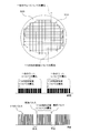
- FIG. 2 is a diagram illustrating an outline of the operation of the laser apparatus according to the embodiment of the present disclosure.
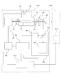
- FIG. 3 is a diagram illustrating a configuration of a laser apparatus according to an embodiment of the present disclosure.
- FIG. 4 is a diagram illustrating a configuration of the narrowband module in the laser apparatus according to the embodiment of the present disclosure.
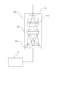
- FIG. 5 is a diagram illustrating a configuration of a spectrometer in the laser apparatus according to the embodiment of the present disclosure.
- FIG. 1 is a diagram illustrating a schematic configuration of a laser device according to an embodiment of the present disclosure.
- FIG. 2 is a diagram illustrating an outline of the operation of the laser apparatus according to the embodiment of the present disclosure.
- FIG. 3 is a diagram illustrating a configuration of a laser apparatus according to an embodiment of the present disclosure.
- FIG. 4 is a diagram illustrating a configuration of the narrowband
- FIG. 6 is a diagram illustrating a configuration of a control unit in the laser apparatus according to the embodiment of the present disclosure.
- FIG. 7 is a diagram illustrating a problem of related technology related to the laser apparatus according to the embodiment of the present disclosure.
- FIG. 8 is a diagram illustrating an outline of a method for controlling the wavelength of the laser according to the first embodiment of the present disclosure.
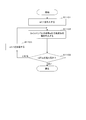
- FIG. 9 is a diagram illustrating a flowchart of a method for controlling the wavelength of a laser according to the first embodiment of the present disclosure.
- FIG. 10 is a diagram illustrating target wavelength data of pulsed laser light in the method for controlling the laser wavelength according to the first embodiment of the present disclosure.
- FIG. 11 is a diagram illustrating a subroutine for writing target wavelength data in the storage unit in the method for controlling the wavelength of the laser according to the first embodiment of the present disclosure.
- FIG. 12 is a diagram illustrating a first example of a wavelength control subroutine in the method for controlling the wavelength of a laser according to the first embodiment of the present disclosure.
- FIG. 13 is a diagram illustrating a second example of a wavelength control subroutine in the method for controlling the wavelength of a laser according to the first embodiment of the present disclosure.
- FIG. 14 is a diagram illustrating an outline of a method for controlling the wavelength of a laser according to the second embodiment of the present disclosure.
- FIG. 15 is a diagram illustrating a flowchart of a method for controlling the wavelength of a laser according to the second embodiment of the present disclosure.
- FIG. 16 is a diagram illustrating a subroutine for calculating the number of delayed pulses and writing to the storage unit in the method for controlling the wavelength of the laser according to the second embodiment of the present disclosure.
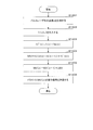
- FIG. 17 is a diagram illustrating a flowchart for the exposure apparatus control unit in the method for controlling the wavelength of the laser according to the third embodiment of the present disclosure.
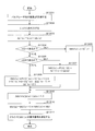
- FIG. 18 is a diagram illustrating a flowchart for the wavelength control unit in the method of controlling the wavelength of the laser according to the third embodiment of the present disclosure.
- Laser apparatus according to an embodiment of the present disclosure 1.1 Outline of a laser apparatus according to an embodiment of the present disclosure 1.2 Configuration example of a laser apparatus according to an embodiment of the present disclosure 1.3 Laser apparatus according to an embodiment of the present disclosure 1. Example of operation 2. Problems of related technology related to the laser device according to the embodiment of the present disclosure; 3. Method for Controlling Laser Wavelength According to Embodiment of Present Disclosure 3.1 Method for Controlling Laser Wavelength According to First Embodiment of Present Disclosure 3.2 Wavelength of Laser According to Second Embodiment of Present Disclosure 3.3 Method for Controlling Laser Wavelength According to Third Embodiment of the Present Disclosure
- FIG. 1 is a diagram illustrating an outline of a configuration of a laser device according to an embodiment of the present disclosure.
- Laser device 100 may be configured to emit pulsed laser light L.
- the laser device 100 may include a laser control unit 110.
- the laser apparatus 100 may be an exposure apparatus laser apparatus that is used together with the exposure apparatus 200.
- the exposure apparatus 200 may be a semiconductor exposure apparatus.
- the exposure apparatus 200 may be configured to expose a wafer provided in the exposure apparatus 200 with the pulsed laser light L emitted from the laser apparatus 100.
- the exposure apparatus 200 may include an exposure apparatus control unit 210.
- the laser control unit 110 may be connected to the exposure apparatus control unit 210 via a line.
- the exposure apparatus control unit 210 may include an arithmetic processing device that performs arithmetic processing, a storage device that stores data, and a timer that measures time.
- the laser control unit 110 may receive the light emission trigger signal Str and the target wavelength ⁇ tx from the exposure apparatus control unit 210.
- the laser control unit 110 may control the laser device 100 so that the wavelength of the pulsed laser light L emitted from the laser device 100 becomes the target wavelength ⁇ tx.
- the laser control unit 110 may control the laser device 100 so that the laser device 100 emits pulsed laser light L having a wavelength that is the same as or close to the target wavelength ⁇ tx in synchronization with the light emission trigger signal Str.
- FIG. 2 is a diagram illustrating an outline of the operation of the laser device according to the embodiment of the present disclosure.
- the laser apparatus 100 illustrated in FIG. 1 may expose the wafer 300 provided in the exposure apparatus 200 with pulsed laser light via the exposure apparatus 200 illustrated in FIG. 1.
- the laser apparatus 100 may expose the wafer 300 with pulsed laser light for each of the plurality of rectangular regions 310 set on the wafer 300.
- the laser apparatus 100 may sequentially scan a plurality of rectangular regions 310 on the wafer 300 with pulsed laser light, for example, as indicated by a line with an arrow in FIG.
- the laser apparatus 100 may expose the next wafer 300 with laser light after exposing one wafer 300 with laser light.
- each pulse laser light with a predetermined repetition frequency (for example, 6 kHz) and a predetermined number (for example, several hundreds) of pulses is used.
- the rectangular area 310 may be exposed.
- the exposure with the pulse laser beam is paused at a predetermined time interval (for example, 0.1 seconds to 0.2 seconds or more). May be. Stopping exposure with pulsed laser light at a predetermined time interval and executing exposure with pulsed laser light with a predetermined repetition frequency and a predetermined number of pulses may be called burst mode operation.
- the laser apparatus 100 operates in the burst mode, as illustrated in FIG. 2, exposure with pulsed laser light from the first pulse to the last pulse may be called a burst.
- the exposure apparatus control unit 210 included in the exposure apparatus 200 may transmit the light emission trigger signal Str to the laser control unit 110 included in the laser apparatus 100 so that the laser apparatus 100 performs the burst mode operation. Thereby, the laser apparatus 100 can perform the burst mode operation.
- FIG. 3 is a diagram illustrating a configuration example of a laser device according to an embodiment of the present disclosure.
- the straight line without the arrow in FIG. 3 represents the electrical connection of the elements.
- a straight line with an arrow in FIG. 3 represents the traveling direction of the laser light.
- the laser device illustrated in FIG. 3 may be a narrow-band laser device 100 that can control the wavelength of laser light.
- the narrow-band laser device 100 may be a laser device used with an external device.
- the external apparatus may be the exposure apparatus 200.
- the exposure apparatus 200 may include an exposure apparatus control unit 210.
- the narrow-band laser device 100 may be an excimer laser device.
- the excimer laser device may be an argon fluoride (ArF) excimer laser device or a krypton fluoride (KrF) excimer laser device.
- the narrow-band laser device 100 may be an ultraviolet solid laser device having a variable wavelength.
- the tunable ultraviolet solid state laser device may be, for example, a solid state laser device combining a titanium-sapphire laser and a nonlinear crystal.
- the narrow-band laser device 100 may be a single-stage narrow-band ultraviolet laser.
- the narrow-band laser device 100 may be mounted on a double stage laser system.
- the narrow-band laser apparatus 100 may be mounted on a power amplifier (Power Amplifier (PA)) that amplifies laser light as a master oscillator (Master Oscillator (MO)).
- PA Power Amplifier
- MO Master Oscillator
- the narrow-band laser device 100 may be mounted on a power oscillator (Power Oscillator (PO)) as a master oscillator (Master Oscillator (MO)).
- the narrow-band laser device 100 may include a laser control unit 110.
- the narrow-band laser device 100 may include a laser chamber 10, an output coupling mirror 20, a narrow-band module (LNN) 30, a wavelength controller 40, and a driver 50.
- the narrow-band laser device 100 may include a first beam splitter 60 and a wavelength measurement unit 120.
- the output coupling mirror 20 and the narrowband module 30 may constitute a laser resonator of the narrowband laser device 100 configured to output laser light.
- the laser chamber 10 may be provided on the optical path of the laser resonator.
- the laser chamber 10 may include a first window 11, a second window 12, a pair of electrodes 13, and a power source 14.
- the laser chamber 10 may include a laser medium.
- the laser medium may be a mixed gas containing argon (Ar) gas, fluorine (F 2 ) gas, and neon (Ne) gas. Good.
- the narrow-band laser device 100 is a KrF excimer laser device
- the laser medium may be a mixed gas containing krypton (Kr) gas, fluorine (F 2 ) gas, and neon (Ne) gas. Good.
- the first window 11 and the second window 12 may be provided so as to allow laser light to pass therethrough.
- the pair of electrodes 13 may be provided in the laser chamber 10 so as to face each other in a direction perpendicular to the paper surface of FIG.
- the pair of electrodes 13 may be provided such that the longitudinal direction of the electrodes 13 coincides with the direction of the optical path of the laser resonator.
- the power source 14 may be connected to a pair of electrodes 13.
- the power source 14 may include a power switch 15.
- the power switch 15 may be configured to turn on or off the power supply 14 according to the output of the laser control unit 110.
- the power source 14 may be configured to apply a voltage to the pair of electrodes 13 when the power switch 15 is turned on.
- the output coupling mirror 20 may be coated with a film that reflects part of the laser light and transmits another part of the laser light.
- the narrowband module 30 may be configured to narrow the wavelength width (spectral width) of the laser light.
- the first beam splitter 60 may be provided on the optical path of the laser beam output from the output coupling mirror 20.
- the first beam splitter 60 may be provided so as to transmit a part of the laser light output from the output coupling mirror 20 to the exposure apparatus 200.
- the first beam splitter 60 may be provided so as to reflect another part of the laser light toward the wavelength measuring unit 120.
- the wavelength measuring unit 120 may be configured to measure the wavelength of the pulsed laser light.
- the wavelength measurement unit 120 may include a second beam splitter 70, an optical sensor 80, and a spectrometer 90.
- the second beam splitter 70 may be provided on the optical path of the laser light reflected by the first beam splitter 60.
- the second beam splitter 70 may be provided so as to transmit part of the laser light reflected by the first beam splitter 60 to the spectrometer 90.
- the second beam splitter 70 may be provided to reflect another part of the laser light reflected by the first beam splitter 60 toward the optical sensor 80.
- the optical sensor 80 may be provided so as to detect the laser beam reflected from the second beam splitter 70.
- the output of the optical sensor 80 may be transmitted to the wavelength controller 40.
- the optical sensor 80 may be connected to the wavelength control unit 40.
- the spectroscope 90 may be provided so as to receive the laser light transmitted through the second beam splitter 70.
- the spectroscope 90 may be configured to measure the wavelength of the laser light.
- the spectroscope 90 may be capable of measuring the wavelength of laser light for each laser pulse.
- the output of the spectroscope 90 may be transmitted to the wavelength controller 40.
- the spectroscope 90 may be connected to the wavelength controller 40.
- the wavelength controller 40 may be configured to receive the output of the optical sensor 80 included in the wavelength measuring unit 120.
- the wavelength control unit 40 may be connected to the optical sensor 80 included in the wavelength measurement unit 120.
- the wavelength control unit 40 may be configured to receive the output of the spectrometer 90 included in the wavelength measurement unit 120.
- the wavelength control unit 40 may be connected to the spectroscope 90 included in the wavelength measurement unit 120.
- the wavelength control unit 40 may be configured to receive the output of the laser control unit 110 and transmit the output of the wavelength control unit 40 to the laser control unit 110.
- the wavelength control unit 40 may be connected to the laser control unit 110.
- the wavelength control unit 40 may be configured to transmit the output of the wavelength control unit 40 to the driver 50.
- the wavelength control unit 40 may be connected to the driver 50.
- the wavelength control unit 40 may include an arithmetic processing unit that performs arithmetic processing.
- the wavelength control unit 40 may include a storage unit that stores the result of the arithmetic processing executed by the arithmetic processing unit.
- the wavelength controller 40 may include a timer that measures time.
- the laser control unit 110 may be configured to receive the output of the exposure apparatus control unit 210 included in the exposure apparatus 200.
- the laser control unit 110 may be connected to an exposure apparatus control unit 210 included in the exposure apparatus 200.
- the laser control unit 110 may be configured to receive the output of the wavelength control unit 40 and transmit the output of the laser control unit 110 to the wavelength control unit 40.
- the laser control unit 110 may be configured to transmit the output of the laser control unit 110 to the power supply 14.
- the laser control unit 110 may be connected to the power source 14.
- the driver 50 may be configured to control the band narrowing module 30.
- the driver 50 may be configured to receive the output of the wavelength controller 40 and transmit the output of the driver 50 to the narrowband module 30.
- the driver 50 may be connected to the band narrowing module 30 and the wavelength control unit 40.
- At least two of the laser control unit 110, the wavelength control unit 40, and the driver 50 in the narrow-band laser device 100 illustrated in FIG. 3 may be integrated.
- FIG. 4 is a diagram illustrating a configuration of the narrowband module in the laser apparatus according to the embodiment of the present disclosure.
- the band narrowing module 30 may include a plurality of prisms (for example, two prisms including a first prism 31 and a second prism 32), a grating 33, and a rotating stage 34.
- the driver 50 may be provided so as to control the rotation of the rotary stage 34 included in the narrowband module 30 in accordance with the output from the wavelength controller 40.
- the first prism 31 and the second prism 32 may be provided so as to function as a beam expander.
- the second prism 32 may be provided on the rotary stage 34.
- the grating 33 may be provided so that the diffraction angle of the laser beam completely or substantially coincides with the incident angle of the laser beam, that is, in a Littrow arrangement.
- the rotation stage 34 may be configured to rotate the second prism 32.
- the rotation stage 34 may be provided so that the incident angle of laser light having a certain wavelength to the grating 33 is changed by rotating the second prism 32.
- the rotation stage 34 may be configured to rotate the first prism 31 or the grating 33 instead of the second prism 32.
- the first prism 31 or the grating 33 may be provided on the rotary stage 34.
- the band narrowing module 30 may include a micrometer 35 with a pulse motor (stepping motor), a piezo element 36, and a reaction force spring member 37.
- the micrometer 35 with a pulse motor (stepping motor), the piezo element 36, and the reaction force spring member 37 may constitute an actuator that drives the rotary stage 34 included in the band narrowing module 30.
- the actuator may be configured to change the wavelength of the pulsed laser light.
- the micrometer 35 may be configured to receive a signal from the driver 50 and apply a weight to the piezo element 36.
- the micrometer 35 may be connected to the driver 50.
- the driver 50 may include a power source for driving a pulse motor (stepping motor) of the micrometer 35 according to the output from the wavelength control unit 40.
- the piezo element 36 may be provided at the tip of a micrometer head 38 of the micrometer 35.
- the piezo element 36 may be configured to rotate the rotary stage 34 according to the load applied from the micrometer 35.
- the piezo element 36 may be connected to the driver 50.
- the driver 50 may include a power source for applying a voltage to the piezo element 36 and deforming the piezo element 36 in accordance with the output from the wavelength control unit 40.
- the piezo element 36 may be configured to be deformed in accordance with the applied voltage and to rotate the rotary stage 34.
- the reaction force spring member 37 may be configured to apply a reaction force to the piezo element 36 so that the piezo element 36 is stationary with respect to a load applied from the micrometer 35 to the piezo element 36.
- FIG. 5 is a diagram illustrating a configuration of a spectrometer in the laser device according to the embodiment of the present disclosure.
- the spectroscope 90 may be an etalon spectroscope.
- the spectroscope 90 may include a diffusing element 91, a monitor etalon 92, a condenser lens 93, and an image sensor 94.
- the diffusion element 91, the monitor etalon 92, the condenser lens 93, and the image sensor 94 may be provided in this order.
- the diffusing element 91 may be provided so as to diffuse the laser light transmitted through the second beam splitter 70.
- the monitor etalon 92 may be an air gap etalon, for example.
- the monitor etalon 92 may be provided so as to receive the laser light diffused by the diffusing element 91 and to interfere with the laser light diffused by the diffusing element 91.
- the condensing lens 93 may be configured to condense the laser light transmitted through the monitor etalon 92 onto the image sensor 94.
- the image sensor 94 may be, for example, a line sensor such as a one-dimensional CCD or a photodiode array.
- the image sensor 94 may be provided on the focal plane of the condenser lens 93. On the focal plane of the condenser lens 93, interference fringes of the laser light that has passed through the monitor etalon 92 may occur.
- the image sensor 94 may detect interference fringes of laser light that has passed through the monitor etalon 92.
- the square of the radius of the interference fringes generated on the focal plane of the condenser lens 93 may be proportional to the wavelength of the laser light.
- ⁇ c is a wavelength at which the light intensity of the interference fringes of the detected laser light is maximized.
- ⁇ is a proportionality constant.
- the spectral profile of the laser beam may be detected from the interference pattern of the laser beam detected by the image sensor 94.
- the center wavelength of the spectral line of the laser light and the width of the spectral line may be detected from the interference fringes of the laser light detected by the image sensor 94.
- the center wavelength of the spectral line of the laser light and the width of the spectral line may be detected by an information processing device not illustrated in the figure, or may be calculated by the wavelength control unit 40.
- Spectrometer 90 may include a plurality of etalon spectrometers having different free spectral ranges.
- the spectroscope 90 may be a spectroscope including a grating and an image sensor.
- the grating may be provided so as to diffract the light transmitted through the second beam splitter 70.
- the spectral profile of the laser light diffracted by the grating may be detected by an image sensor.
- the center wavelength of the spectral line of the laser light and the width of the spectral line may be detected by the image sensor.
- the center wavelength of the spectral line of the laser light and the width of the spectral line may be detected by an information processing device not illustrated in the figure, or may be calculated by the wavelength control unit 40.
- the wavelength controller 40 may be configured to control an actuator included in the narrowband module 30 based on the wavelength of the laser light measured by the wavelength measuring unit 120.
- FIG. 6 is a diagram illustrating a configuration of a control unit in the laser apparatus according to the embodiment of the present disclosure.
- Each control unit (controller) in the above-described embodiment may be configured by a general-purpose control device such as a computer or a programmable controller.
- a general-purpose control device such as a computer or a programmable controller.
- it may be configured as follows.
- the control unit includes a processing unit 1000, a storage memory 1005, a user interface 1010, a parallel I / O controller 1020, a serial I / O controller 1030, A / D, and D / A connected to the processing unit 1000. And a converter 1040. Further, the processing unit 1000 may include a CPU 1001, a memory 1002, a timer 1003, and a GPU 1004 connected to the CPU 1001.
- the processing unit 1000 may read a program stored in the storage memory 1005.
- the processing unit 1000 may execute the read program, read data from the storage memory 1005 in accordance with execution of the program, or store data in the storage memory 1005.
- the parallel I / O controller 1020 may be connected to a communicable device via a parallel I / O port.
- the parallel I / O controller 1020 may control communication using a digital signal via a parallel I / O port that is performed in the process in which the processing unit 1000 executes a program.
- the serial I / O controller 1030 may be connected to a communicable device via a serial I / O port.
- the serial I / O controller 1030 may control communication using a digital signal via a serial I / O port that is performed in a process in which the processing unit 1000 executes a program.
- the A / D and D / A converter 1040 may be connected to a communicable device via an analog port.
- the A / D and D / A converter 1040 may control communication using an analog signal via an analog port that is performed in the process in which the processing unit 1000 executes a program.
- the user interface 1010 may be configured such that the operator displays a program execution process by the processing unit 1000, or causes the processing unit 1000 to stop program execution or interrupt processing by the operator.
- the CPU 1001 of the processing unit 1000 may perform arithmetic processing of a program.
- the memory 1002 may temporarily store a program during the course of execution of the program by the CPU 1001 or temporarily store data during a calculation process.
- the timer 1003 may measure time and elapsed time and output the time and elapsed time to the CPU 1001 according to execution of the program.
- the GPU 1004 may process the image data according to the execution of the program and output the result to the CPU 1001.
- the device connected to the parallel I / O controller 1020 and capable of communicating via the parallel I / O port may be the optical sensor 80, the image sensor 94, another control unit, or the like.
- the device connected to the serial I / O controller 1030 and capable of communicating via the serial I / O port may be another control unit or the like.
- the device connected to the A / D and D / A converter 1040 and capable of communicating via an analog port may be an optical sensor 80, an image sensor 94, or the like.
- the exposure apparatus controller 210 included in the exposure apparatus 200 may transmit data of the target wavelength ⁇ tx of the laser light and the light emission trigger signal Str to the laser controller 110 included in the laser apparatus 100.
- the laser control unit 110 may transmit the light emission trigger signal Str received from the exposure apparatus control unit 210 to the power supply 14.
- the laser control unit 110 may transmit the data of the target wavelength ⁇ tx received from the exposure apparatus control unit 210 to the wavelength control unit 40.
- the power supply 14 may turn on or off the power switch 15 included in the power supply 14 in synchronization with the light emission trigger signal Str received from the laser control unit 110.
- a voltage may be applied between the pair of electrodes 13 included in the laser chamber 10.
- the laser medium included in the laser chamber 10 may be discharged, and pulsed laser light may be generated from the laser medium by stimulated emission.
- the pulsed laser beam generated from the laser medium is reciprocated through the first window 11 and the second window 12 and amplified between the output coupling mirror 20 and the narrowband module 30 constituting the laser resonator. Good.
- a part of the amplified pulsed laser light may pass through the output coupling mirror 20.
- a part of the pulse laser beam transmitted through the output coupling mirror 20 may be incident on the first beam splitter 60.
- a part of the light incident on the first beam splitter 60 may be transmitted to the first beam splitter 60 and input to the exposure apparatus 200 (laser oscillation).
- the narrowband module 30 may receive pulsed laser light generated from the laser medium through the second window 12.
- the narrowband module 30 is configured to split the received pulsed laser beam with respect to the wavelength of the pulsed laser beam by the first prism 31, the second prism 32, and the grating 33, thereby narrowing the pulsed laser beam. May be generated.
- the band narrowing module 30 may rotate the second prism 32 by rotating the rotary stage 34 according to the output of the driver 50.
- the band narrowing module 30 may change the incident angle of the pulsed laser light incident on the grating 33 by rotating the second prism 32.
- the wavelength of the pulsed laser light that is diffracted by the grating 33 and reflected toward the laser chamber 10 may be selected (the pulsed laser light is narrowed). Bandwidth may be used).
- the wavelength of the pulse laser beam may be selected according to the incident angle of the pulse laser beam with respect to the grating 33 and the diffraction angle of the pulse laser beam with respect to the grating 33.
- the rotation stage 34 included in the narrowband module 30 may be driven by a micrometer 35 controlled according to the output of the driver 50.
- the rotary stage 34 included in the narrowband module 30 may be driven by a piezo element 36 controlled according to the output of the driver 50.
- the rotation stage 34 is driven by the piezo element 36 in addition to the micrometer 35, so that the response time of the rotation stage 34 to the output of the driver 50 can be improved.
- a part of the pulse laser beam reflected by the first beam splitter 60 may be input to the wavelength measuring unit 120.
- the pulse laser beam input to the wavelength measuring unit 120 may be incident on the second beam splitter 70.
- a part of the pulsed laser light incident on the second beam splitter 70 may be reflected to the optical sensor 80.
- the optical sensor 80 may receive the pulse laser beam reflected by the optical sensor 80 and transmit a detection signal of the pulse laser beam to the wavelength control unit 40.
- a part of the pulsed laser light incident on the second beam splitter 70 may pass through the second beam splitter 70 and enter the spectroscope 90.
- the pulsed laser light incident on the spectroscope 90 may pass through the diffusion element 91 and be diffused.
- the pulsed laser light that passes through the diffusion element 91 and is diffused by the diffusion element 91 may enter the monitor etalon 92.
- the monitor etalon 92 may cause the pulsed laser light incident on the monitor etalon 92 to interfere.
- the pulsed laser light interfered by the monitor etalon 92 may be incident on the condenser lens 93.
- the pulsed laser light incident on the condenser lens 93 may pass through the condenser lens 93 and generate a circular interference fringe on the focal plane of the condenser lens 93.
- the pulsed laser light transmitted through the condenser lens 93 may be condensed on the image sensor 94.
- the image sensor 94 may be arranged on the focal plane of the condenser lens 93 and detect a circular interference fringe generated on the focal plane of the condenser lens 93.
- a signal corresponding to the interference fringe detected by the image sensor 94 may be transmitted to the wavelength controller 40.
- the wavelength controller 40 may receive data of the target wavelength ⁇ tx of the pulse laser beam from the laser controller 110.
- the wavelength control unit 40 may transmit a signal for controlling the rotation stage 34 included in the narrowband module 30 to the driver 50 based on the data of the target wavelength ⁇ tx of the pulsed laser light.
- the wavelength of the pulse laser beam may be selected by controlling the rotary stage 34 included in the narrowband module 30 via the driver 50.
- the wavelength controller 40 may receive a signal transmitted from the optical sensor 80 and a signal corresponding to the interference fringe transmitted from the image sensor 94 of the spectrometer 90 included in the wavelength measuring unit 120.
- the wavelength controller 40 may calculate (measure) the wavelength of the pulsed laser light from the data of the signal corresponding to the interference fringes.
- FIG. 7 is a diagram illustrating a problem of related technology related to a laser device according to an embodiment of the present disclosure.
- the focus of the pulsed laser beam is varied according to the variation in the height of the wafer surface with respect to the wafer position.
- the position of can be changed.
- the wavelength of the pulsed laser beam emitted from the laser device can be changed for each laser pulse.
- the inclined surface on the surface of the wafer can be exposed and scanned with pulsed laser light.
- the data of the target wavelength ⁇ tx for each laser pulse transmitted from the exposure device control unit of the exposure device to the laser control unit of the laser device is obtained on the surface of the wafer. It can vary depending on the height of the slope.
- the wavelength of the pulsed laser light operated by the actuator included in the laser device can vary depending on the height of the slope on the surface of the wafer in accordance with the data of the target wavelength ⁇ tx that varies depending on the height of the slope on the surface of the wafer.
- the wavelength of the pulsed laser light operated by the actuator included in the laser device can be, for example, the wavelength of the pulsed laser light to be achieved by the rotation of the rotary stage included in the narrowband module.
- the actual pulse laser beam May not match the target wavelength ⁇ tx.
- the response time of the actuator included in the laser apparatus is longer than a predetermined repetition period (for example, 1/6000 second (repetition frequency 6 kHz)) in the burst mode operation of the laser apparatus, the actual pulse laser beam The wavelength may not match the target wavelength ⁇ tx.
- the actuator included in the laser device is operated for each laser pulse according to the data of the target wavelength ⁇ tx, the actual wavelength of the pulsed laser light may not match the target wavelength ⁇ tx.
- the wavelength of the actual pulsed laser light emitted from the laser device matches the target wavelength ⁇ tx.
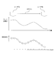
- FIG. 8 is a diagram of a laser according to the first embodiment of the present disclosure. It is a figure which illustrates the outline of the method of controlling a wavelength.
- the pulse laser beam is changed according to the variation of the height of the wafer surface with respect to the wafer position.
- the focus position may be changed.
- the wavelength of the pulse laser beam emitted from the laser device 100 may be changed for each laser pulse.
- the inclined surface on the surface of the wafer 300 may be exposed and scanned with pulsed laser light.
- the data of the target wavelength ⁇ tx for each laser pulse transmitted from the exposure apparatus control unit 210 to the laser control unit 110 is the data on the slope on the surface of the wafer 300.
- the wavelength control unit 40 included in the laser apparatus 100 receives data of the target wavelength ⁇ tx of the pulsed laser light for the plurality of laser pulses from the exposure apparatus control unit 210 before outputting the pulsed laser light from the laser apparatus 100. May be configured.
- the wavelength control unit 40 may be configured to receive data of the target wavelength ⁇ tx of the pulse laser light for a plurality of laser pulses before outputting one burst of the pulse laser light.
- the data of the target wavelength ⁇ tx of the pulse laser beam for a plurality of laser pulses may include data of the target wavelength ⁇ tx for a plurality of pulses included in one burst of the pulse laser beam.
- the wavelength control unit 40 determines the wavelength of the pulsed laser light operated by the actuator depending on the data of the target wavelength ⁇ tx that varies depending on the height of the slope on the surface of the wafer 300 and the response time of the actuator included in the laser device 100. It may be changed.
- the wavelength of the pulsed laser light operated by the actuator included in the laser apparatus 100 may be, for example, the wavelength of the pulsed laser light to be achieved by the rotation of the rotary stage 34 included in the narrowband module 30.
- the wavelength controller 40 may control the actuator included in the laser device 100 based on the change in the height of the slope on the surface of the wafer 300 and the response time of the actuator.
- the wavelength control unit 40 is configured to change the wavelength of the pulsed laser light operated by the actuator included in the laser device 100 at least the response time of the actuator before the time when the target wavelength ⁇ tx of the pulsed laser light is changed. May be.
- the wavelength control unit 40 may be configured to control the actuator based on the data of the target wavelength ⁇ tx of the pulsed laser light for the plurality of laser pulses and the response time of the actuator included in the laser device 100. For example, depending on the response time of the actuator included in the laser apparatus 100, the wavelength control unit 40 may read out the target wavelength ⁇ tx of the pulse laser light ahead by the amount of the plurality of laser pulses corresponding to the response time of the actuator. Good. The wavelength control unit 40 sets the wavelength of the pulsed laser light operated by the actuator included in the laser device 100 according to the target wavelength ⁇ tx of the pulsed laser light ahead by a plurality of laser pulses corresponding to the response time of the actuator. It may be changed. For example, as illustrated in FIG. 8, the target wavelength ⁇ tx of the pulse laser beam ahead by two pulses is read and the actuator is controlled according to the target wavelength ⁇ tx of the pulse laser light ahead by two pulses. Also good.
- the wavelength control unit 40 may be configured to control the actuator so that the wavelength of the actual pulsed laser light emitted from the laser device 100 approaches the data of the target wavelength ⁇ tx.
- the wavelength control unit 40 controls the actuator according to the target wavelength ⁇ tx of the pulse laser beam ahead by a plurality of laser pulses corresponding to the response time of the actuator, thereby setting the wavelength of the actual pulsed laser beam to the target wavelength ⁇ tx. Can be close to the data. For example, as illustrated in FIG. 8, by controlling the actuator in accordance with the target wavelength ⁇ tx of the previous pulsed laser beam by two pulses, the actual wavelength of the pulsed laser beam is brought closer to the data of the target wavelength ⁇ tx. be able to.
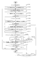
- FIG. 9 is a diagram illustrating a flowchart of the method for controlling the wavelength of the laser according to the first embodiment of the present disclosure.
- the wavelength control unit 40 included in the laser apparatus 100 that operates in the burst mode operates from the exposure apparatus control unit 210 via the laser control unit 110 to obtain the target wavelength ⁇ tx of the pulse laser light for each laser pulse for one burst. May be received.
- the data of the target wavelength ⁇ tx of the pulsed laser light for each laser pulse for one burst is data ⁇ tx (1) of a plurality of target wavelengths ⁇ tx for one burst including ne laser pulses from the first pulse to the last pulse.
- ... ⁇ tx (n) may mean the target wavelength ⁇ tx of the pulse laser beam for the nth laser pulse from the first pulse to the last pulse.
- step S902 the wavelength controller 40 receives data ⁇ tx (1),..., ⁇ tx (n),... ⁇ tx (ne) of a plurality of target wavelengths ⁇ tx for one burst including ne laser pulses. You may write in the memory
- the wavelength controller 40 may read the target wavelength ⁇ tx (1) of the first pulse of one burst.
- the wavelength controller 40 may substitute the target wavelength ⁇ tx (1) of the leading pulse for the initial wavelength ⁇ t (0) of the pulsed laser light operated by the actuator.
- the wavelength controller 40 may calculate the initial value MV (0) of the actuator operation amount corresponding to the initial wavelength ⁇ t (0) of the pulsed laser light operated by the actuator.
- the wavelength control unit 40 may transmit the initial value MV (0) of the actuator operation amount to the driver 50 that controls the actuator so that the wavelength of the pulse laser beam becomes the target wavelength ⁇ tx (1) of the head pulse.
- the laser apparatus 100 transmits the initial value MV (0) of the actuator operation amount to the driver 50 in advance during the pause period in the burst mode operation, so that the wavelength of the first pulse in the burst is changed to the target wavelength ⁇ tx (1 ).
- the wavelength controller 40 may reset the time T measured by the timer included in the wavelength controller 40 and start measuring the time T by the timer.
- the timer may monitor the pause time in the burst mode operation of the laser apparatus 100 by measuring the time T.
- the wavelength control unit 40 may send a light emission trigger acceptance signal to the exposure apparatus control unit 210 to prepare for receiving the light emission trigger signal from the exposure apparatus control unit 210.
- the wavelength control unit 40 may determine whether or not the laser control unit 110 has received a light emission trigger signal from the exposure apparatus control unit 210.
- step S909 may be executed. If the laser control unit 110 has not received a light emission trigger signal from the exposure apparatus control unit 210, step S908 may be repeated until the laser control unit 110 receives a light emission trigger signal from the exposure apparatus control unit 210.
- the wavelength control unit 40 may determine whether or not the time T measured by the timer is equal to or longer than the predetermined time K. It may be determined whether or not the pause time in the burst mode operation of the laser apparatus 100 is equal to or longer than a predetermined time K. When the pause time in the burst mode operation of the laser device 100 is equal to or longer than the predetermined time K, the pulse of the pulsed laser light emitted from the laser device 100 may be determined as the first pulse of the burst. When the pause time in the burst mode operation of the laser apparatus 100 is equal to or longer than the predetermined time K, step S910 may be executed.
- step S911 may be executed.
- the wavelength controller 40 may substitute 1 for the laser pulse number n.
- the wavelength control unit 40 may add 1 to the laser pulse number n.
- the wavelength control unit 40 may reset the time T measured by the timer included in the wavelength control unit 40 and start measuring the time T by the timer.
- the timer may monitor the time in the burst in the burst mode operation of the laser apparatus 100 by measuring the time T.
- the wavelength controller 40 may acquire the number of delayed pulses nf depending on the response time of the actuator included in the laser device 100.
- the number of delayed pulses nf may be 2, for example.
- step S ⁇ b> 914 the wavelength control unit 40 may read out the target wavelength ⁇ tx (n + nf) of the pulse laser beam corresponding to the laser pulse preceding the laser pulse number n by the delay pulse number nf from the storage unit. Good.
- the wavelength control unit 40 may determine whether there is data of the target wavelength ⁇ tx (n + nf) of the pulse laser beam.
- the wavelength control unit 40 determines whether or not the laser pulse number n + nf is equal to or smaller than the laser pulse number ne which is the last pulse in the burst (whether or not the laser pulse number n is equal to or smaller than ne ⁇ nf). May be.
- the wavelength control unit 40 may execute step S916. If there is no data of the target wavelength ⁇ tx (n + nf) of the pulse laser beam (the laser pulse number n exceeds ne ⁇ nf), the wavelength controller 40 may execute step S917.
- step S916 the target wavelength ⁇ tx (n + nf) of the pulse laser beam corresponding to the laser pulse of the laser pulse number n + nf is substituted for the wavelength ⁇ t (n) of the pulse laser beam operated by the actuator for the laser pulse of the laser pulse number n. May be.
- step S917 the target wavelength ⁇ tx (ne) of the pulse laser beam corresponding to the laser pulse of the laser pulse number ne is substituted for the wavelength ⁇ t (n) of the pulse laser beam operated by the actuator for the laser pulse of the laser pulse number n.
- the target wavelength ⁇ tx () of the pulse laser beam corresponding to the last pulse in the burst is added to the wavelength ⁇ t (n) of the pulse laser beam operated by the actuator.
- ne) may be substituted.
- the wavelength control unit 40 may execute a wavelength control subroutine to be described later.
- the wavelength control unit 40 may calculate an actuator operation amount value MV (n) corresponding to the wavelength ⁇ t (n) of the pulsed laser light operated by the actuator by executing a wavelength control subroutine.
- the wavelength control unit 40 executes the wavelength control subroutine, and sends the actuator operation amount value MV to the driver 50 that controls the actuator so that the wavelength of the pulsed laser light becomes the target wavelength ⁇ tx (n) of the pulsed laser light. (N) may be transmitted.
- the laser device 100 transmits the actuator operation amount value MV (n) to the driver 50 in advance, whereby the wavelength of the pulse laser beam can be brought close to the target wavelength ⁇ tx (n) of the pulse laser beam. .
- the wavelength control unit 40 may determine whether or not the laser apparatus 100 has finished the burst in the burst mode operation.
- the wavelength controller 40 may determine whether the laser pulse number n exceeds the laser pulse number ne, which is the last pulse in the burst.
- step S920 may be executed. If the laser device 100 has not finished the burst in the burst mode operation (the laser pulse number n is equal to or less than the laser pulse number ne which is the last pulse in the burst), the steps S908 to 919 are repeatedly executed. May be.
- step S920 it may be determined whether or not to end the control of the wavelength of the pulse laser beam. If the control of the wavelength of the pulse laser beam is not terminated, Steps S901 to S920 may be repeated.
- FIG. 10 is a diagram illustrating target wavelength data of pulsed laser light in the method for controlling the wavelength of the laser according to the first embodiment of the present disclosure.
- the data of the target wavelength ⁇ tx of the pulse laser beam transmitted from the exposure apparatus controller 210 to the laser controller 110 is the pulse laser beam corresponding to the pulse number #n and the pulse number #n. It may be composed of ne sets of target wavelengths ⁇ tx (n).
- the set of the target wavelength ⁇ tx (1) of the pulse laser beam corresponding to the pulse number # 1 and the pulse number # 1 is the number of the laser pulse of the first pulse in one burst and the target of the pulse laser beam of the first pulse in one burst, respectively.
- the wavelength ⁇ tx (1) may be used.
- the sets of the target wavelength ⁇ tx (ne) of the pulse laser beam corresponding to the pulse number #ne and the pulse number #ne are respectively the laser pulse number of the last pulse in one burst and the target of the pulse laser beam of the last pulse in one burst.
- the wavelength may be ⁇ tx (ne).
- the data of the target wavelength ⁇ tx of the pulse laser beam transmitted from the exposure apparatus controller 210 to the laser controller 110 is data on laser pulses included in a plurality of bursts in the exposure of one wafer 300 with the pulse laser beam. May be.
- FIG. 11 is a diagram illustrating a subroutine for writing target wavelength data in the storage unit in the method for controlling the wavelength of the laser according to the first embodiment of the present disclosure.
- the wavelength controller 40 may substitute 1 for the laser pulse number n.
- the wavelength control unit 40 may substitute the value of the target wavelength of the pulsed laser beam corresponding to the laser pulse number n transmitted from the exposure apparatus control unit 210 into the variable ⁇ tx (n).
- the wavelength controller 40 may determine whether or not the laser pulse number n exceeds the number ne of laser pulses (the last pulse number ne in one burst). When the number n of laser pulses exceeds the number ne of laser pulses, the subroutine for writing the target wavelength data in the storage unit may be terminated and the process may return to the main routine. If the number n of laser pulses is equal to or less than the number ne of laser pulses, step S1104 may be executed.
- step S1104 the wavelength controller 40 may add 1 to the laser pulse number n and return to step S1102.
- the wavelength controller 40 can write ne sets of the target wavelength ⁇ tx (n) of the pulse laser beam corresponding to the pulse number #n and the pulse number #n in the storage unit.
- FIG. 12 is a diagram illustrating a first example of a wavelength control subroutine in the method for controlling the wavelength of a laser according to the first embodiment of the present disclosure.
- the first example of the wavelength control subroutine in the method for controlling the wavelength of the laser according to the first embodiment of the present disclosure illustrated in FIG. 12 may not include PID control.
- the wavelength measuring unit 120 may measure the actual wavelength ⁇ of the pulsed laser light and transmit the measured wavelength ⁇ to the wavelength control unit 40.
- the wavelength control unit 40 may substitute the measured wavelength ⁇ for the actual wavelength ⁇ (n) of the pulse laser beam for the laser pulse number n.
- the wavelength control unit 40 may calculate a variation value ⁇ SV of the actuator operation amount.
- the fluctuation value ⁇ SV of the actuator operation amount is the difference between the wavelengths ⁇ t (n ⁇ 1) and ⁇ t (n) of the pulse laser light operated by the actuator for the laser pulses of numbers n ⁇ 1 and n and ⁇ ′ (n ).
- the wavelength controller 40 may calculate the actuator operation amount MV (n) for the laser pulse number n.
- the actuator operation amount MV (n) for the laser pulse number n is calculated based on the actuator operation amount MV (n-1) for the laser pulse number n-1 and the fluctuation value ⁇ SV of the actuator operation amount. May be.
- step S ⁇ b> 1206 the wavelength control unit 40 may transmit the actuator operation amount MV (n) signal for the laser pulse number n to the driver 50.
- the driver 50 may control the actuator based on the actuator operation amount MV (n) for the laser pulse number n.
- the wavelength control unit 40 may control the actuator based on the difference between the target wavelength data of the pulse laser beam and the wavelength of the pulse laser beam measured by the wavelength measurement unit.
- FIG. 13 is a diagram illustrating a second example of the wavelength control subroutine in the method for controlling the wavelength of the laser according to the first embodiment of the present disclosure.
- the second example of the wavelength control subroutine in the method for controlling the wavelength of the laser according to the first embodiment of the present disclosure illustrated in FIG. 13 may include PID control.
- Step S1301 may be the same as step S1201 illustrated in FIG.
- Step S1302 may be the same as step S1202 illustrated in FIG.
- Step S1303 may be the same as step S1203 illustrated in FIG.
- step S1304 the wavelength controller 40 may determine whether the laser pulse number n is 1. When the laser pulse number n is 1, the wavelength controller 40 may execute step S1305. If the laser pulse number n is not 1, the wavelength controller 40 may execute step S1306.
- the wavelength control unit 40 may calculate the PID control value ⁇ MV (n) for the actuator operation amount MV (n) for the laser pulse number n.
- I may be a proportionality constant in PID control.
- I may include a coefficient for converting the wavelength of the pulsed laser light into an actuator operation amount. I may be obtained in advance by, for example, changing the target wavelength of the pulsed laser light in a stepwise manner and measuring the change in the wavelength of the pulsed laser light.
- step S1306 the wavelength controller 40 may determine whether the laser pulse number n is 2. When the laser pulse number n is 2, the wavelength controller 40 may execute step S1307. If the laser pulse number n is not 2, the wavelength controller 40 may execute step S1308.
- the wavelength control unit 40 may calculate the PID control value ⁇ MV (n) for the actuator operation amount MV (n) for the laser pulse number n.
- P and I may be proportional constants in PID control.
- P and I may include a coefficient for converting the wavelength of the pulsed laser light into an actuator operation amount.
- P and I may be obtained in advance by, for example, changing the target wavelength of the pulsed laser light in a stepwise manner and measuring the change in the wavelength of the pulsed laser light.
- the wavelength controller 40 may calculate the PID control value ⁇ MV (n) for the actuator operation amount MV (n) for the laser pulse number n.
- P, I, and D may be proportional constants in PID control.
- P, I, and D may include a coefficient for converting the wavelength of the pulsed laser light into an actuator operation amount.
- P, I, and D may be obtained in advance by, for example, changing the target wavelength of the pulsed laser light in a stepwise manner and measuring the change in the wavelength of the pulsed laser light.
- the wavelength controller 40 may calculate the fluctuation value ⁇ SV of the actuator operation amount other than the PID control.
- the fluctuation value ⁇ SV of the actuator operation amount other than the PID control is the difference between the wavelengths ⁇ t (n ⁇ 1) and ⁇ t (n) of the pulse laser light operated by the actuator for the laser pulses of numbers n ⁇ 1 and n. It may be calculated based on.
- the wavelength control unit 40 may calculate the actuator operation amount MV (n) for the laser pulse number n.
- the actuator operation amount MV (n) for the laser pulse number n is the actuator operation amount MV (n-1), the PID control value ⁇ MV (n), and the actuator operation amount for the laser pulse number n ⁇ 1. It may be calculated based on the fluctuation value ⁇ SV.
- Step S1311 may be the same as step S1206 illustrated in FIG.
- the wavelength control unit 40 may control the actuator by PID control based on the difference between the target wavelength data of the pulsed laser light and the wavelength of the pulsed laser light measured by the wavelength measuring unit.
- the PID control based on the difference between the target wavelength data of the pulsed laser beam and the wavelength of the pulsed laser beam measured by the wavelength measuring unit enables the control of the wavelength of the pulsed laser beam with respect to the change in the target wavelength of the pulsed laser beam. Stability can be improved.
- PID control may be control related to at least one of P, I, and D.
- Control other than PID control (feedback control) based on the difference ⁇ ′ (n) between the actual wavelength ⁇ (n) of the pulse laser beam for the laser pulse number n and the target wavelength ⁇ tx (n) for the laser pulse number n May be performed.
- FIG. 14 is a diagram illustrating an outline of a method for controlling the wavelength of a laser according to the second embodiment of the present disclosure.
- unevenness may exist on the surface of the wafer 300 provided in the exposure apparatus 200 in the scanning direction of the pulse laser beam.
- the unevenness of the surface of the wafer 300 existing in the direction of scanning the pulsed laser light may mean that the height of the surface of the wafer 300 in the direction of scanning the pulsed laser light has at least one of maximum and minimum.
- the pulsed laser beam is changed according to the unevenness of the surface of the wafer 300 with respect to the position of the wafer 300.
- the focus position may be changed.
- the wavelength of the pulse laser beam emitted from the laser device 100 may be changed for each laser pulse.
- the unevenness on the surface of the wafer 300 is exposed with the pulsed laser light. You may scan.
- the data of the target wavelength ⁇ tx for each laser pulse transmitted from the exposure apparatus controller 210 to the laser controller 110 is determined by the unevenness on the surface of the wafer 300. Can vary.
- the wavelength control unit 40 included in the laser apparatus 100 receives data of the target wavelength ⁇ tx of the pulsed laser light for the plurality of laser pulses from the exposure apparatus control unit 210 before outputting the pulsed laser light from the laser apparatus 100. May be configured.
- the wavelength controller 40 may calculate the response time of the actuator included in the laser device 100 from the data of the target wavelength ⁇ tx that varies depending on the unevenness on the surface of the wafer 300.
- the response time of the actuator included in the laser apparatus 100 may be calculated from, for example, a curve relationship of the target wavelength ⁇ tx that varies depending on the unevenness of the surface of the wafer 300 with respect to the position of the wafer 300 in the scanning direction of the pulsed laser light.
- the number of delayed pulses for each laser pulse may be calculated.
- the response time of the actuator included in the laser apparatus 100 may vary due to unevenness on the surface of the wafer 300.
- the wavelength of the pulsed laser light operated by the actuator may be changed based on the response time of the actuator that varies depending on the unevenness on the surface of the wafer 300.
- the wavelength control unit 40 may control the actuator included in the laser device 100 based on the response time of the actuator that varies due to unevenness on the surface of the wafer 300.
- the wavelength control unit 40 is configured to change the wavelength of the pulsed laser light operated by the actuator included in the laser device 100 at least the response time of the actuator before the time when the target wavelength ⁇ tx of the pulsed laser light is changed. May be.
- the wavelength control unit 40 may be configured to control the actuator based on the response time of the actuator that varies due to unevenness on the surface of the wafer 300.
- the wavelength control unit 40 may be configured to control the actuator so that the wavelength of the actual pulsed laser light emitted from the laser device 100 approaches the data of the target wavelength ⁇ tx.
- FIG. 15 is a diagram illustrating a flowchart of a method for controlling the wavelength of a laser according to the second embodiment of the present disclosure.
- Step S1501 may be the same as step S901 illustrated in FIG.
- Step S1502 may be the same as step S902 illustrated in FIG.
- the wavelength control unit 40 may calculate the number of delayed pulses nf for each laser pulse based on data of the target wavelength ⁇ tx that varies depending on the unevenness of the surface of the wafer in the scanning direction of the pulsed laser light.
- the wavelength controller 40 may write the number of delayed pulses nf calculated for each laser pulse in a storage unit included in the wavelength controller 40.
- Step S1504 may be the same as step S903 illustrated in FIG.
- Step S1505 may be the same as step S904 illustrated in FIG.
- Step S1506 may be the same as step S905 illustrated in FIG.
- Step S1507 may be the same as step S906 illustrated in FIG.
- Step S1508 may be the same as step S907 illustrated in FIG.
- Step S1509 may be the same as step S908 illustrated in FIG.
- Step S1510 may be the same as step S909 illustrated in FIG.
- Step S1511 may be the same as step S910 illustrated in FIG.
- Step S1512 may be the same as step S911 illustrated in FIG.
- Step S1513 may be the same as step S912 illustrated in FIG.
- the wavelength control unit 40 may read the delay pulse number nf (n) for the laser pulse number n of the laser pulse from the storage unit included in the wavelength control unit 40.
- the wavelength controller 40 may substitute the delayed pulse number nf (n) for the laser pulse number n of the laser pulse into the delayed pulse number nf.
- Step S1516 may be the same as step S914 illustrated in FIG.
- Step S1517 may be the same as step S915 illustrated in FIG.
- Step S1518 may be the same as step S916 illustrated in FIG.
- Step S1519 may be the same as step S917 illustrated in FIG.
- Step S1520 may be the same as step S918 illustrated in FIG.
- Step S1521 may be the same as step S919 illustrated in FIG.
- Step S1522 may be the same as step S920 illustrated in FIG.
- FIG. 16 is a diagram illustrating a subroutine for calculating the number of delayed pulses and writing to the storage unit in the method for controlling the wavelength of the laser according to the second embodiment of the present disclosure.
- the wavelength control unit 40 may read data of the target wavelength ⁇ tx of the pulsed laser light for each laser pulse from the exposure apparatus control unit 210 via the laser control unit 110.
- Data of the target wavelength ⁇ tx of the pulse laser beam for each laser pulse is data ⁇ tx (1),..., ⁇ tx (n),. ne).
- ⁇ tx (n) may mean the target wavelength ⁇ tx of the pulse laser beam for the nth laser pulse among the ne pulses.
- the wavelength control unit 40 determines from the change in the data ⁇ tx (1),..., ⁇ tx (n),... ⁇ tx (ne) of the target wavelength ⁇ tx of the pulse laser beam for the laser pulse number n.
- the number of delayed pulses nf (1),..., nf (n),..., nf (ne) for the ne laser pulses may be calculated.
- the data ⁇ tx (1),..., ⁇ tx (n),... ⁇ tx (ne) of the target wavelength ⁇ tx of the pulse laser beam for the laser pulse number n is proportional to the differential coefficient of the approximate curve.
- the number of delayed pulses nf (1),..., nf (n),..., nf (ne) for the ne laser pulses may be calculated.
- step S1603 the wavelength control unit 40 transmits the data of the delayed pulse numbers nf (1),..., Nf (n),..., Nf (ne) calculated for the ne laser pulses to the wavelength control unit. You may write in the memory
- An exposure apparatus control unit 210 included in the exposure apparatus 200 is included in the laser apparatus in advance from the laser control unit 110 included in the laser apparatus 100. You may receive the delay pulse number of the laser pulse according to the response time of an actuator. For each laser pulse, the laser controller 110 outputs a pulse laser target wavelength ⁇ tx (n) for the laser pulse number n, the laser pulse number n from the exposure apparatus controller 210, and a wavelength for operating the actuator. ⁇ t (n) may be received. Even in this case, the actual wavelength of the pulsed laser light emitted from the laser device 100 can be controlled similarly.
- FIG. 17 is a diagram illustrating a flowchart for the exposure apparatus control unit in the method of controlling the wavelength of the laser according to the third embodiment of the present disclosure.
- the exposure apparatus control unit 210 may measure irregularities on the surface of the wafer 300 provided in the exposure apparatus 200.
- step S ⁇ b> 1702 the exposure apparatus control unit 210 calculates the wavelength of the pulsed laser light to be emitted from the laser apparatus 100 performing the burst mode operation for each laser pulse based on the measurement values of the unevenness on the surface of the wafer 300. Also good.
- step S1703 the exposure apparatus control unit 210 uses the exposure apparatus control section to store the data ⁇ tx (1),..., ⁇ tx (n) of the target wavelength ⁇ tx of the pulse laser beam for n laser pulses included in one burst. You may write in the memory
- the exposure apparatus control unit 210 may receive the delay pulse number nf for the laser pulse of the pulsed laser light from the laser control unit 110 included in the laser apparatus 100.
- the delay pulse number nf for the laser pulse of the pulsed laser light may depend on the response time of the actuator included in the laser apparatus 100.
- step S1705 the exposure apparatus controller 210 substitutes 0 for the laser pulse number n of the pulse laser beam.
- step S1706 the exposure apparatus controller 210 sets the target wavelength ⁇ tx (1) of the pulse laser beam for the first laser pulse (first pulse) to the initial wavelength ⁇ t (0) of the pulse laser beam operated by the actuator. You may substitute.
- the exposure apparatus control unit 210 may wait for a predetermined time (for example, a burst pause time in the burst mode operation of the laser apparatus 100).
- step S1709 the exposure apparatus control unit 210 transmits a light emission trigger signal Str to the laser control unit 110 included in the laser apparatus 100.
- the exposure apparatus control unit 210 may reset the time T measured by the timer included in the exposure apparatus control unit 210 and start measuring the time T by the timer.
- the timer may monitor the time interval of the laser pulse included in the burst in the burst mode operation of the laser apparatus 100 by measuring the time T.
- step S1711 the exposure apparatus controller 210 may add 1 to the laser pulse number n of the pulse laser beam.
- the exposure apparatus control unit 210 may determine whether there is data of the target wavelength ⁇ tx (n + nf) of the pulse laser beam.
- the exposure apparatus controller 210 determines whether or not the laser pulse number n + nf is equal to or smaller than the laser pulse number ne (the laser pulse number n is equal to or smaller than ne ⁇ nf). You may do. If there is data of the target wavelength ⁇ tx (n + nf) of the pulse laser beam (the laser pulse number n is equal to or smaller than ne ⁇ nf), the exposure apparatus control unit 210 may execute step S1713. If there is no data of the target wavelength ⁇ tx (n + nf) of the pulse laser beam (the number n of the laser pulses exceeds ne ⁇ nf), the exposure apparatus control unit 210 may execute step S1714.
- step S1713 the target wavelength ⁇ tx (n + nf) of the pulse laser beam corresponding to the laser pulse of the laser pulse number n + nf is substituted for the wavelength ⁇ t (n) of the pulse laser beam operated by the actuator for the laser pulse of the laser pulse number n. May be.
- step S1714 the target wavelength ⁇ tx (ne) of the pulse laser beam corresponding to the laser pulse of the laser pulse number ne is substituted for the wavelength ⁇ t (n) of the pulse laser beam operated by the actuator for the laser pulse of the laser pulse number n. May be.
- step S1715 the exposure apparatus control unit 210 sends to the laser control unit 110, for each laser pulse, a pulse laser target wavelength ⁇ tx (n) for the laser pulse number n and the laser pulse number n and the actuator pulse.
- a wavelength ⁇ t (n) for operation may be transmitted.
- the exposure apparatus control unit 210 may determine whether or not the laser apparatus 100 has finished the burst in the burst mode operation.
- the exposure apparatus controller 210 may determine whether the laser pulse number n is the laser pulse number ne, which is the last pulse in the burst.
- step S1717 may be executed. If the laser device 100 has not finished the burst in the burst mode operation (the laser pulse number n is not the laser pulse number ne which is the last pulse in the burst), step S1718 may be executed.
- step S1717 it may be determined whether or not to end the control of the wavelength of the pulsed laser beam. If the control of the wavelength of the pulse laser beam is not terminated, Steps S1703 to S1718 may be repeated.
- the exposure apparatus controller 210 may determine whether or not the time T measured by the timer is equal to or longer than the repetition period 1 / f of the laser pulse included in the burst.
- f may be a repetition frequency of a laser pulse included in a burst in the burst mode operation of the laser apparatus 100.
- the exposure apparatus control unit 210 may repeatedly execute steps S1709 to S1718.
- Step S1718 may be repeated.
- FIG. 18 is a diagram illustrating a flowchart for the wavelength control unit in the method for controlling the wavelength of the laser according to the third embodiment of the present disclosure.
- step S1801 the wavelength control unit 40 included in the laser apparatus 100 sends the delay pulse number nf for the laser pulse of the pulse laser light to the exposure apparatus control unit 210 included in the exposure apparatus 200 via the laser control unit 110. You may send it.
- the delay pulse number nf for the laser pulse of the pulsed laser light may depend on the response time of the actuator included in the laser apparatus 100.
- step S1802 for each laser pulse, the wavelength control unit 40, via the laser control unit 110, outputs the target wavelength of the pulse laser for the laser pulse number n and the laser pulse number n from the exposure apparatus control unit 210.
- ⁇ tx (n) and a wavelength ⁇ t (n) for operating the actuator may be received.
- step S1803 the wavelength controller 40 may determine whether the laser pulse number n is not 0. If the laser pulse number n is not 0, the wavelength controller 40 may execute step S1804. When the laser pulse number n is 0, the wavelength controller 40 may execute Steps S1809 and S1810.
- Step S1804 may be the same as step S1201 illustrated in FIG.
- Step S1805 may be the same as step S1202 illustrated in FIG.
- Step S1806 may be the same as step S1203 illustrated in FIG.
- Step S1807 may be the same as step S1204 illustrated in FIG.
- Step S1808 may be the same as step S1205 illustrated in FIG.
- the wavelength controller 40 may calculate the initial value MV (0) of the actuator operation amount corresponding to the initial wavelength ⁇ t (0) of the pulsed laser light operated by the actuator.
- h may be a coefficient for converting the wavelength of the pulsed laser light into an actuator operation amount.
- the wavelength control unit 40 may substitute the initial value MV (0) of the actuator operation amount for the actuator operation amount MV (n) for the laser pulse number n.
- Step S1811 may be the same as step S1206 illustrated in FIG.
- step S1812 it may be determined whether or not to end the control of the wavelength of the pulse laser beam. If the control of the wavelength of the pulse laser beam is not completed, Steps S1802 to 1812 may be repeated.
Landscapes
- Physics & Mathematics (AREA)
- Electromagnetism (AREA)
- Engineering & Computer Science (AREA)
- Plasma & Fusion (AREA)
- Optics & Photonics (AREA)
- Lasers (AREA)
Abstract
レーザ装置(100)は、パルスレーザ光(L)を出力するように構成されたレーザ共振器(20,30)と、前記パルスレーザ光の波長を変化させるように構成されたアクチュエータ(35,36,37)と、前記パルスレーザ光を出力する前に前記パルスレーザ光の複数のパルスについての目標波長のデータを受信すると共に前記複数のパルスについての前記目標波長のデータに基づいて前記パルスレーザ光の波長が前記目標波長のデータに近づくように前記アクチュエータを制御するように構成された制御部(110)とを含むものであってもよい。
Description
本開示は、レーザ装置及びアクチュエータを制御する方法に関する。
半導体集積回路の微細化、高集積化につれて、半導体露光装置においては解像力の向上が要請されている。半導体露光装置を以下、単に「露光装置」という。このため露光用光源から出力される光の短波長化が進められている。露光用光源には、従来の水銀ランプに代わってガスレーザ装置が用いられている。現在、露光用のガスレーザ装置としては、波長248nmの紫外線を出力するKrFエキシマレーザ装置ならびに、波長193nmの紫外線を出力するArFエキシマレーザ装置が用いられている。
現在の露光技術としては、露光装置側の投影レンズとウエハ間の間隙を液体で満たして、当該間隙の屈折率を変えることによって、露光用光源の見かけの波長を短波長化する液浸露光が実用化されている。ArFエキシマレーザ装置を露光用光源として用いて液浸露光が行われた場合は、ウエハには水中における波長134nmの紫外光が照射される。この技術をArF液浸露光という。ArF液浸露光はArF液浸リソグラフィーとも呼ばれる。
KrF、ArFエキシマレーザ装置の自然発振におけるスペクトル線幅は約350~400pmと広いため、露光装置側の投影レンズによってウエハ上に縮小投影されるレーザ光(紫外線光)の色収差が発生して解像力が低下する。そこで色収差が無視できる程度となるまでガスレーザ装置から出力されるレーザ光のスペクトル線幅を狭帯域化する必要がある。スペクトル線幅はスペクトル幅とも呼ばれる。このためガスレーザ装置のレーザ共振器内には狭帯域化素子を有する狭帯域化モジュール(Line Narrow Module)が設けられ、この狭帯域化モジュールによりスペクトル幅の狭帯域化が実現されている。なお、狭帯域化素子はエタロンやグレーティング等であってもよい。このようにスペクトル幅が狭帯域化されたレーザ装置を狭帯域化レーザ装置という。
レーザ装置(100)は、パルスレーザ光(L)を出力するように構成されたレーザ共振器(20,30)と、前記パルスレーザ光の波長を変化させるように構成されたアクチュエータ(35,36,37)と、前記パルスレーザ光を出力する前に前記パルスレーザ光の複数のパルスについての目標波長のデータを受信すると共に前記複数のパルスについての前記目標波長のデータに基づいて前記パルスレーザ光の波長が前記目標波長のデータに近づくように前記アクチュエータを制御するように構成された制御部(110)とを含むものであってもよい。
パルスレーザ光(L)の波長を変化させるように構成されたアクチュエータ(35,36,37)を制御する方法は、前記アクチュエータの応答時間に依存して、前記パルスレーザ光の目標波長を変化させる時刻よりも少なくとも前記応答時間分先に、前記パルスレーザ光の波長を変化させることを含むものであってもよい。
本開示のいくつかの実施形態を、単なる例として、添付の図面を参照して以下に説明する。
図1は、本開示の実施形態に係るレーザ装置の構成の概略を例示する図である。
図2は、本開示の実施形態に係るレーザ装置の動作の概略を例示する図である。
図3は、本開示の実施形態に係るレーザ装置の構成を例示する図である。
図4は、本開示の実施形態に係るレーザ装置における狭帯域化モジュールの構成を例示する図である。
図5は、本開示の実施形態に係るレーザ装置における分光器の構成を例示する図である。
図6は、本開示の実施形態に係るレーザ装置における制御部の構成を例示する図である。
図7は、本開示の実施形態に係るレーザ装置に関する関連技術の課題を例示する図である。
図8は、本開示の第一の実施形態に係るレーザの波長を制御する方法の概略を例示する図である。
図9は、本開示の第一の実施形態に係るレーザの波長を制御する方法のフローチャートを例示する図である。
図10は、本開示の第一の実施形態に係るレーザの波長を制御する方法におけるパルスレーザ光の目標波長のデータを例示する図である。
図11は、本開示の第一の実施形態に係るレーザの波長を制御する方法における目標波長のデータを記憶部に書き込むサブルーチンを例示する図である。
図12は、本開示の第一の実施形態に係るレーザの波長を制御する方法における波長制御サブルーチンの第一の例を例示する図である。
図13は、本開示の第一の実施形態に係るレーザの波長を制御する方法における波長制御サブルーチンの第二の例を例示する図である。
図14は、本開示の第二の実施形態に係るレーザの波長を制御する方法の概略を例示する図である。
図15は、本開示の第二の実施形態に係るレーザの波長を制御する方法のフローチャートを例示する図である。
図16は、本開示の第二の実施形態に係るレーザの波長を制御する方法における遅れパルス数を計算すると共に記憶部に書き込むサブルーチンを例示する図である。
図17は、本開示の第三の実施形態に係るレーザの波長を制御する方法における露光装置制御部用のフローチャートを例示する図である。
図18は、本開示の第三の実施形態に係るレーザの波長を制御する方法における波長制御部用のフローチャートを例示する図である。
内容
1.本開示の実施形態に係るレーザ装置
1.1 本開示の実施形態に係るレーザ装置の概略
1.2 本開示の実施形態に係るレーザ装置の構成例
1.3 本開示の実施形態に係るレーザ装置の動作例
2.本開示の実施形態に係るレーザ装置に関する関連技術の課題
3.本開示の実施形態に係るレーザの波長を制御する方法
3.1 本開示の第一の実施形態に係るレーザの波長を制御する方法
3.2 本開示の第二の実施形態に係るレーザの波長を制御する方法
3.3 本開示の第三の実施形態に係るレーザの波長を制御する方法
1.本開示の実施形態に係るレーザ装置
1.1 本開示の実施形態に係るレーザ装置の概略
1.2 本開示の実施形態に係るレーザ装置の構成例
1.3 本開示の実施形態に係るレーザ装置の動作例
2.本開示の実施形態に係るレーザ装置に関する関連技術の課題
3.本開示の実施形態に係るレーザの波長を制御する方法
3.1 本開示の第一の実施形態に係るレーザの波長を制御する方法
3.2 本開示の第二の実施形態に係るレーザの波長を制御する方法
3.3 本開示の第三の実施形態に係るレーザの波長を制御する方法
以下、本開示の実施形態について、図面を参照しながら詳しく説明する、以下に説明される実施形態は、本開示のいくつかの例を示すものであって、本開示の内容を限定するものではない。また、各実施形態で説明される構成及び動作の全てが本開示の構成及び動作として必須であるとは限らない。なお、同一の構成要素には同一の参照符号を付して、重複する説明を省略する。
1.本開示の実施形態に係るレーザ装置
1.1 本開示の実施形態に係るレーザ装置の概略
図1は、本開示の実施形態に係るレーザ装置の構成の概略を例示する図である。
1.1 本開示の実施形態に係るレーザ装置の概略
図1は、本開示の実施形態に係るレーザ装置の構成の概略を例示する図である。
レーザ装置100は、パルスレーザ光Lを放出するように構成されてもよい。レーザ装置100は、レーザ制御部110を含んでもよい。レーザ装置100は、露光装置200と共に使用される露光装置用レーザ装置であってもよい。
露光装置200は、半導体露光装置であってもよい。露光装置200は、レーザ装置100から放出されるパルスレーザ光Lで露光装置200に設けられたウェハを露光するように構成されてもよい。露光装置200は、露光装置制御部210を含んでもよい。レーザ制御部110は、ラインを介して露光装置制御部210と接続されてもよい。露光装置制御部210は、演算処理を行う演算処理装置、データを記憶する記憶装置、時間を計測するタイマを含んでもよい。
レーザ制御部110は、露光装置制御部210から発光トリガ信号Strと目標波長λtxを受信してもよい。
レーザ制御部110は、レーザ装置100から放出されるパルスレーザ光Lの波長が目標波長λtxとなるように、レーザ装置100を制御してもよい。
レーザ制御部110は、レーザ装置100が発光トリガ信号Strに同期して目標波長λtxと同一の又はそれに近い波長のパルスレーザ光Lを放出するように、レーザ装置100を制御してもよい。
図2は、本開示の実施形態に係るレーザ装置の動作の概略を例示する図である。
図2に例示するように、図1に例示するレーザ装置100は、図1に例示する露光装置200を介して、露光装置200に設けられたウェハ300をパルスレーザ光で露光してもよい。レーザ装置100は、例えば、ウェハ300に設定された複数の矩形領域310毎にウェハ300をパルスレーザ光で露光してもよい。レーザ装置100は、例えば、図2の矢印付きの線で示すように、ウェハ300における複数の矩形領域310をパルスレーザ光で順次スキャンしてもよい。レーザ装置100は、一枚のウェハ300をレーザ光で露光した後、次のウェハ300をレーザ光で露光してもよい。
図2に例示するように、一枚のウェハ300をレーザ光で露光するとき、所定の繰り返し周波数(例えば、6kHz)と所定の数(例えば、数百個)のパルスのパルスレーザ光で各々の矩形領域310を露光してもよい。一つの矩形領域310についての露光と次の矩形領域310についての露光との間に、所定の時間間隔(例えば、0.1秒~0.2秒以上)でパルスレーザ光での露光を休止してもよい。所定の時間間隔でパルスレーザ光での露光を休止すると共に所定の繰り返し周波数と所定の数のパルスでパルスレーザ光での露光を実行することをバーストモード運転と呼んでもよい。レーザ装置100がバーストモード運転するとき、図2に例示されるように、先頭パルスから最終パルスまでのパルスレーザ光での露光をバーストと呼んでもよい。
露光装置200に含まれる露光装置制御部210は、レーザ装置100がバーストモード運転を実行するように、発光トリガ信号Strをレーザ装置100に含まれるレーザ制御部110へ送信してもよい。それによって、レーザ装置100は、バーストモード運転を実行することができる。
1.2 本開示の実施形態に係るレーザ装置の構成例
図3は、本開示の実施形態に係るレーザ装置の構成例を例示する図である。図3における矢印無しの直線は、要素の電気的な接続を表す。図3における矢印付きの直線は、レーザ光の進行方向を表す。
図3は、本開示の実施形態に係るレーザ装置の構成例を例示する図である。図3における矢印無しの直線は、要素の電気的な接続を表す。図3における矢印付きの直線は、レーザ光の進行方向を表す。
図3に例示されたレーザ装置は、レーザ光の波長を制御することが可能な狭帯域化レーザ装置100であってもよい。狭帯域化レーザ装置100は、外部装置と共に使用されるレーザ装置であってもよい。外部装置は、露光装置200であってもよい。露光装置200は、露光装置制御部210を含んでもよい。
狭帯域化レーザ装置100は、エキシマレーザ装置であってもよい。エキシマレーザ装置は、フッ化アルゴン(ArF)エキシマレーザ装置又はフッ化クリプトン(KrF)エキシマレーザ装置であってもよい。狭帯域化レーザ装置100は、波長可変な紫外線固体レーザ装置であってもよい。波長可変な紫外線固体レーザ装置は、例えば、チタン-サファイアレーザと非線形結晶を組合せた固体レーザ装置であってもよい。
狭帯域化レーザ装置100は、シングルステージの狭帯域紫外線レーザであってもよい。狭帯域化レーザ装置100は、ダブルステージレーザシステムに搭載されてもよい。例えば、狭帯域化レーザ装置100をマスターオシレータ(Master Ocillator(MO))としてレーザ光を増幅するパワー増幅器(Power Amplifier(PA))に搭載してもよい。例えば、狭帯域化レーザ装置100をマスターオシレータ(Master Ocillator(MO))としてパワーオシレータ(Power Oscillater(PO))に搭載してもよい。
狭帯域化レーザ装置100は、レーザ制御部110を含むものであってもよい。狭帯域化レーザ装置100は、レーザチャンバ10と、出力結合ミラー20と、狭帯域化モジュール(Line Narrowing Module(LNM))30と、波長制御部40と、ドライバ50を含んでもよい。狭帯域化レーザ装置100は、第一のビームスプリッタ60と、波長計測部120を含んでもよい。出力結合ミラー20と狭帯域化モジュール30は、レーザ光を出力するように構成された、狭帯域化レーザ装置100のレーザ共振器を構成してもよい。
レーザチャンバ10は、レーザ共振器の光路上に設けられてもよい。レーザチャンバ10は、第一のウィンドウ11と、第二のウィンドウ12と、一対の電極13と、電源14とを含んでもよい。
レーザチャンバ10は、レーザ媒質を含んでもよい。狭帯域化レーザ装置100が、ArFエキシマレーザ装置である場合には、レーザ媒質は、アルゴン(Ar)ガスと、フッ素(F2)ガスと、ネオン(Ne)ガスを含む混合ガスであってもよい。狭帯域化レーザ装置100が、KrFエキシマレーザ装置である場合には、レーザ媒質は、クリプトン(Kr)ガスと、フッ素(F2)ガスと、ネオン(Ne)ガスを含む混合ガスであってもよい。
第一のウィンドウ11と第二のウィンドウ12は、レーザ光を通過させるように設けられてもよい。
一対の電極13は、レーザチャンバ10内において図3の紙面に対して垂直な方向に対向するように設けられてもよい。一対の電極13は、電極13の長手方向がレーザ共振器の光路の方向と一致するように設けられていてもよい。
電源14は、一対の電極13と接続されていてもよい。電源14は、電源スイッチ15を含んでもよい。電源スイッチ15は、レーザ制御部110の出力に応じて、電源14をオンする又はオフするように構成されてもよい。電源14は、電源スイッチ15がオンになるとき、一対の電極13に電圧を印加するように構成されてもよい。
出力結合ミラー20は、レーザ光の一部を反射させると共にレーザ光の別の一部を透過させる膜がコートされていてもよい。
狭帯域化モジュール30は、レーザ光の波長の幅(スペクトル幅)を狭帯域化するように構成されてもよい。
第一のビームスプリッタ60は、出力結合ミラー20から出力されるレーザ光の光路上に設けられてもよい。第一のビームスプリッタ60は、出力結合ミラー20から出力されたレーザ光の一部を露光装置200へ透過させるように設けられてもよい。第一のビームスプリッタ60は、レーザ光の別の一部を波長計測部120に向かって反射させるように、設けられてもよい。
波長計測部120は、パルスレーザ光の波長を計測するように構成されてもよい。波長計測部120は、第二のビームスプリッタ70、光センサ80と、分光器90を含んでもよい。
第二のビームスプリッタ70は、第一のビームスプリッタ60によって反射されたレーザ光の光路上に設けられてもよい。第二のビームスプリッタ70は、第一のビームスプリッタ60によって反射されたレーザ光の一部を分光器90へ透過させるように設けられてもよい。第二のビームスプリッタ70は、第一のビームスプリッタ60によって反射されたレーザ光の別の一部を光センサ80に向かって反射させるように、設けられてもよい。
光センサ80は、第二のビームスプリッタ70から反射されたレーザ光を検出するように設けられてもよい。光センサ80の出力は、波長制御部40へ送信されてもよい。光センサ80は、波長制御部40に接続されてもよい。
分光器90は、第二のビームスプリッタ70を透過したレーザ光を受光するように設けられてもよい。分光器90は、レーザ光の波長を計測するように構成されてもよい。分光器90は、レーザパルス毎にレーザ光の波長を計測することが可能なものであってもよい。分光器90の出力は、波長制御部40へ送信されてもよい。分光器90は、波長制御部40に接続されてもよい。
波長制御部40は、波長計測部120に含まれる光センサ80の出力を受信するように構成されてもよい。波長制御部40は、波長計測部120に含まれる光センサ80と接続されてもよい。波長制御部40は、波長計測部120に含まれる分光器90の出力を受信するように構成されてもよい。波長制御部40は、波長計測部120に含まれる分光器90と接続されてもよい。波長制御部40は、レーザ制御部110の出力を受信すると共に波長制御部40の出力をレーザ制御部110へ送信するように構成されてもよい。波長制御部40は、レーザ制御部110と接続されてもよい。波長制御部40は、波長制御部40の出力をドライバ50へ送信するように構成されてもよい。波長制御部40は、ドライバ50と接続されてもよい。波長制御部40は、演算処理を実行する演算処理部を含んでもよい。波長制御部40は、演算処理部によって実行された演算処理の結果を記憶する記憶部を含んでもよい。波長制御部40は、時間を計測するタイマを含んでもよい。
レーザ制御部110は、露光装置200に含まれる露光装置制御部210の出力を受信するように構成されてもよい。レーザ制御部110は、露光装置200に含まれる露光装置制御部210に接続されてもよい。レーザ制御部110は、波長制御部40の出力を受信すると共にレーザ制御部110の出力を波長制御部40へ送信するように構成されてもよい。レーザ制御部110は、電源14へレーザ制御部110の出力を送信するように構成されてもよい。レーザ制御部110は、電源14に接続されてもよい。
ドライバ50は、狭帯域化モジュール30を制御するように構成されてもよい。ドライバ50は、波長制御部40の出力を受信すると共にドライバ50の出力を狭帯域化モジュール30に送信するように構成されてもよい。ドライバ50は、狭帯域化モジュール30と波長制御部40に接続されてもよい。
図3に例示した狭帯域化レーザ装置100におけるレーザ制御部110と、波長制御部40と、ドライバ50の少なくとも二つが、一体化されていてもよい。
図4は、本開示の実施形態に係るレーザ装置における狭帯域化モジュールの構成を例示する図である。
狭帯域化モジュール30は、複数のプリズム(例えば、第一のプリズム31と第二のプリズム32からなる二個のプリズム)と、グレーティング33と、回転ステージ34を含んでもよい。ドライバ50は、波長制御部40からの出力に応じて、狭帯域化モジュール30に含まれる回転ステージ34の回転を制御するように設けられてもよい。
第一のプリズム31と第二のプリズム32は、ビームエキスパンダとして機能するように設けられてもよい。第二のプリズム32は、回転ステージ34に設けられてもよい。
グレーティング33は、レーザ光の回折角がレーザ光の入射角と完全に又は実質的に一致するように、すなわち、リトロー配置に、設けられてもよい。
回転ステージ34は、第二のプリズム32を回転させるように構成されてもよい。回転ステージ34は、第二のプリズム32を回転させることによって、グレーティング33へのある波長のレーザ光の入射角が変化するように設けられてもよい。回転ステージ34は、第二のプリズム32に代えて、第一のプリズム31又はグレーティング33を回転させるように構成されてもよい。第二のプリズム32に代えて、第一のプリズム31又はグレーティング33が回転ステージ34に設けてられもよい。
狭帯域化モジュール30は、パルスモータ(ステッピングモータ)付きマイクロメータ35と、ピエゾ素子36と、反力バネ部材37を含んでもよい。パルスモータ(ステッピングモータ)付けマイクロメータ35と、ピエゾ素子36と、反力バネ部材37は、狭帯域化モジュール30に含まれる回転ステージ34を駆動するアクチュエータを構成してもよい。アクチュエータは、パルスレーザ光の波長を変化させるように構成されてもよい。
マイクロメータ35は、ドライバ50からの信号を受信すると共にピエゾ素子36に加重を与えるように構成されてもよい。マイクロメータ35は、ドライバ50に接続されてもよい。ドライバ50は、波長制御部40からの出力に応じて、マイクロメータ35のパルスモータ(ステッピングモータ)を駆動させるための電源を含んでもよい。
ピエゾ素子36は、マイクロメータ35のマイクロメータヘッド38の先端に設けられてもよい。ピエゾ素子36は、マイクロメータ35から与えられた荷重に応じて回転ステージ34を回転させるように構成されてもよい。ピエゾ素子36は、ドライバ50に接続されてもよい。ドライバ50は、波長制御部40からの出力に応じて、ピエゾ素子36に電圧を印加すると共にピエゾ素子36を変形させるための電源を含んでもよい。ピエゾ素子36は、印加された電圧に応じて変形すると共に回転ステージ34を回転させるように構成されてもよい。
反力バネ部材37は、マイクロメータ35からピエゾ素子36に与えられた荷重に対してピエゾ素子36を静止させるように、ピエゾ素子36に反力を与えるように構成されてもよい。
図5は、本開示の実施形態に係るレーザ装置における分光器の構成を例示する図である。
分光器90は、エタロン分光器であってもよい。分光器90は、拡散素子91と、モニタエタロン92と、集光レンズ93と、イメージセンサ94を含んでもよい。分光器90において、拡散素子91、モニタエタロン92と、集光レンズ93、イメージセンサ94の順に設けられてもよい。
拡散素子91は、第二のビームスプリッタ70を透過したレーザ光を拡散するように設けられてもよい。
モニタエタロン92は、例えば、エアギャップエタロンであってもよい。モニタエタロン92は、拡散素子91によって拡散されたレーザ光を受光すると共に拡散素子91によって拡散されたレーザ光を干渉させるように設けられてもよい。
集光レンズ93は、モニタエタロン92を透過したレーザ光をイメージセンサ94上に集光するように構成されてもよい。
イメージセンサ94は、例えば、1次元のCCD等のラインセンサ、又はフォトダイオードアレイであってもよい。イメージセンサ94は、集光レンズ93の焦点面に設けられてもよい。集光レンズ93の焦点面には、モニタエタロン92を透過したレーザ光の干渉縞が生じてもよい。イメージセンサ94は、モニタエタロン92を透過したレーザ光の干渉縞を検出してもよい。
集光レンズ93の焦点面に生じる干渉縞の半径の二乗は、レーザ光の波長に比例してもよい。レーザ光の波長λは、
λ=λc+αr2
によって表されてもよい。rは、検出されたレーザ光の干渉縞の半径である。λcは、検出されたレーザ光の干渉縞の光強度が最大となる波長である。αは、比例定数である。
λ=λc+αr2
によって表されてもよい。rは、検出されたレーザ光の干渉縞の半径である。λcは、検出されたレーザ光の干渉縞の光強度が最大となる波長である。αは、比例定数である。
イメージセンサ94によって検出されたレーザ光の干渉縞からレーザ光のスペクトルプロファイルが検出されてもよい。イメージセンサ94によって検出されたレーザ光の干渉縞からレーザ光のスペクトル線の中心波長とスペクトル線の幅が検出されてもよい。レーザ光のスペクトル線の中心波長とスペクトル線の幅は、図に例示されない情報処理装置によって検出されてもよく、波長制御部40によって計算されてもよい。
分光器90は、フリースペクトラルレンジの異なる複数のエタロン分光器を含んでいてもよい。
分光器90は、グレーティングと、イメージセンサを含む分光器であってもよい。グレーティングは、第二のビームスプリッタ70を透過した光を回折するように設けられてもよい。グレーティングによって回折されたレーザ光のスペクトルプロファイルが、イメージセンサによって検出されてもよい。レーザ光のスペクトル線の中心波長とスペクトル線の幅が、イメージセンサによって検出されてもよい。レーザ光のスペクトル線の中心波長とスペクトル線の幅は、図に例示されない情報処理装置によって検出されてもよく、波長制御部40によって計算されてもよい。
波長制御部40は、波長計測部120によって計測されたレーザ光の波長に基づいて狭帯域化モジュール30に含まれるアクチュエータを制御するように構成されてもよい。
図6は、本開示の実施形態に係るレーザ装置における制御部の構成を例示する図である。
上述した実施の形態における各制御部(controller)は、コンピュータやプログラマブルコントローラ等汎用の制御機器によって構成されてもよい。たとえば、以下のように構成されてもよい。
制御部は、処理部1000と、処理部1000に接続される、ストレージメモリ1005と、ユーザインターフェイス1010と、パラレルI/Oコントローラ1020と、シリアルI/Oコントローラ1030と、A/D、D/Aコンバータ1040とによって構成されてもよい。また、処理部1000は、CPU1001と、CPU1001に接続された、メモリ1002、タイマ1003、GPU1004とから構成されてもよい。
処理部1000は、ストレージメモリ1005に記憶されたプログラムを読み出してもよい。また、処理部1000は、読み出したプログラムを実行したり、プログラムの実行に従ってストレージメモリ1005からデータを読み出したり、ストレージメモリ1005にデータを記憶させたりしてもよい。
パラレルI/Oコントローラ1020は、パラレルI/Oポートを介して通信可能な機器に接続されてもよい。パラレルI/Oコントローラ1020は、処理部1000がプログラムを実行する過程で行うパラレルI/Oポートを介した、デジタル信号による通信を制御してもよい。
シリアルI/Oコントローラ1030は、シリアルI/Oポートを介して通信可能な機器に接続されてもよい。シリアルI/Oコントローラ1030は、処理部1000がプログラムを実行する過程で行うシリアルI/Oポートを介した、デジタル信号による通信を制御してもよい。
A/D、D/Aコンバータ1040は、アナログポートを介して通信可能な機器に接続されてもよい。A/D、D/Aコンバータ1040は、処理部1000がプログラムを実行する過程で行うアナログポートを介した、アナログ信号による通信を制御してもよい。
ユーザインターフェイス1010は、オペレータが処理部1000によるプログラムの実行過程を表示したり、オペレータによるプログラム実行の中止や割り込み処理を処理部1000に行わせるよう構成されてもよい。
処理部1000のCPU1001はプログラムの演算処理を行ってもよい。メモリ1002は、CPU1001がプログラムを実行する過程で、プログラムの一時記憶や、演算過程でのデータの一時記憶を行ってもよい。タイマ1003は、時刻や経過時間を計測し、プログラムの実行に従ってCPU1001に時刻や経過時間を出力してもよい。GPU1004は、処理部1000に画像データが入力された際、プログラムの実行に従って画像データを処理し、その結果をCPU1001に出力してもよい。
パラレルI/Oコントローラ1020に接続される、パラレルI/Oポートを介して通信可能な機器は、光センサ80、イメージセンサ94、他の制御部等であってもよい。
シリアルI/Oコントローラ1030に接続される、シリアルI/Oポートを介して通信可能な機器は、他の制御部等であってもよい。
A/D、D/Aコンバータ1040に接続される、アナログポートを介して通信可能な機器は、光センサ80、イメージセンサ94等であってもよい。
1.3 本開示の実施形態に係るレーザ装置の動作例
図1、図3、図4、及び図5に基づいて本開示の実施形態に係るレーザ装置の動作例を説明する。
図1、図3、図4、及び図5に基づいて本開示の実施形態に係るレーザ装置の動作例を説明する。
露光装置200に含まれる露光装置制御部210は、レーザ装置100に含まれるレーザ制御部110にレーザ光の目標波長λtxのデータと発光トリガ信号Strを送信してもよい。
レーザ制御部110は、露光装置制御部210から受信した発光トリガ信号Strを電源14へ送信してもよい。レーザ制御部110は、露光装置制御部210から受信した目標波長λtxのデータを波長制御部40へ送信してもよい。
電源14は、レーザ制御部110から受信した発光トリガ信号Strに同期して、電源14に含まれる電源スイッチ15をオン又はオフしてもよい。電源スイッチ15がオンするとき、レーザチャンバ10に含まれる一対の電極13の間に電圧が印加されてもよい。一対の電極13の間に電圧が印加されると、レーザチャンバ10に含まれるレーザ媒質の放電が生じると共に誘導放出によってレーザ媒質からパルスレーザ光が発生してもよい。レーザ媒質から発生したパルスレーザ光は、レーザ共振器を構成する出力結合ミラー20と狭帯域化モジュール30との間で、第一のウィンドウ11と第二のウィンドウ12を通じて往復すると共に増幅されてもよい。増幅されたパルスレーザ光の一部は、出力結合ミラー20を透過してもよい。出力結合ミラー20を透過したパルスレーザ光の一部が、第一のビームスプリッタ60に入射してもよい。第一のビームスプリッタ60に入射した光の一部は、第一のビームスプリッタ60を透過すると共に露光装置200へ入力されてもよい(レーザ発振)。
狭帯域化モジュール30は、第二のウィンドウ12を通じてレーザ媒質から発生したパルスレーザ光を受光してもよい。狭帯域化モジュール30は、第一のプリズム31と第二のプリズム32とグレーティング33によって、受光したパルスレーザ光をパルスレーザ光の波長に対して分光することによって、狭帯域化されたパルスレーザ光を生成させてもよい。狭帯域化モジュール30は、ドライバ50の出力に応じて、回転ステージ34を回転させることによって、第二のプリズム32を回転させてもよい。狭帯域化モジュール30は、第二のプリズム32を回転させることによって、グレーティング33に入射するパルスレーザ光の入射角を変化させてもよい。グレーティング33に入射するパルスレーザ光の入射角を変化させることによって、グレーティング33によって回折されると共にレーザチャンバ10に向かって反射されるパルスレーザ光の波長を選択してもよい(パルスレーザ光を狭帯域化してもよい)。パルスレーザ光の波長は、グレーティング33に対するパルスレーザ光の入射角とグレーティング33に対するパルスレーザ光の回折角に応じて選択されてもよい。
狭帯域化モジュール30に含まれる回転ステージ34は、ドライバ50の出力に応じて制御されたマイクロメータ35によって駆動されてもよい。狭帯域化モジュール30に含まれる回転ステージ34は、ドライバ50の出力に応じて制御されたピエゾ素子36によって駆動されてもよい。回転ステージ34は、マイクロメータ35に加えてピエゾ素子36によって駆動されることによって、ドライバ50の出力に対する回転ステージ34の応答時間を改善することができる。
第一のビームスプリッタ60によって反射されたパルスレーザ光の一部は、波長計測部120に入力されてもよい。
波長計測部120に入力されたパルスレーザ光は、第二のビームスプリッタ70に入射してもよい。
第二のビームスプリッタ70に入射したパルスレーザ光の一部は、光センサ80へ反射されてもよい。光センサ80は、光センサ80へ反射されたパルスレーザ光を受光すると共にパルスレーザ光の検出信号を波長制御部40へ送信してもよい。
第二のビームスプリッタ70に入射したパルスレーザ光の一部は、第二のビームスプリッタ70を透過すると共に分光器90に入射してもよい。
分光器90に入射したパルスレーザ光は、拡散素子91を透過すると共に拡散されてもよい。拡散素子91を透過すると共に拡散素子91によって拡散されたパルスレーザ光は、モニタエタロン92に入射してもよい。モニタエタロン92は、モニタエタロン92に入射したパルスレーザ光を干渉させてもよい。
モニタエタロン92によって干渉させられたパルスレーザ光は、集光レンズ93に入射してもよい。集光レンズ93に入射したパルスレーザ光は、集光レンズ93を透過すると共に集光レンズ93の焦点面に円形の干渉縞を生成してもよい。
集光レンズ93を透過したパルスレーザ光は、イメージセンサ94に集光してもよい。イメージセンサ94は、集光レンズ93の焦点面に配置されると共に集光レンズ93の焦点面に生成する円形の干渉縞を検出してもよい。イメージセンサ94によって検出された干渉縞に対応する信号は、波長制御部40に送信されてもよい。
波長制御部40は、レーザ制御部110からパルスレーザ光の目標波長λtxのデータを受信してもよい。波長制御部40は、パルスレーザ光の目標波長λtxのデータに基づいて、狭帯域化モジュール30に含まれる回転ステージ34を制御するための信号をドライバ50に送信してもよい。パルスレーザ光の波長は、ドライバ50を介して、狭帯域化モジュール30に含まれる回転ステージ34を制御することによって、選択されてもよい。波長制御部40は、光センサ80から送信された信号を受信すると共に、波長計測部120に含まれる分光器90のイメージセンサ94から送信された干渉縞に対応する信号を受信してもよい。波長制御部40は、干渉縞に対応する信号のデータからパルスレーザ光の波長を計算(計測)してもよい。
2.本開示の実施形態に係るレーザ装置に関する関連技術の課題
図7は、本開示の実施形態に係るレーザ装置に関する関連技術の課題を例示する図である。
図7は、本開示の実施形態に係るレーザ装置に関する関連技術の課題を例示する図である。
図7に例示するように、露光装置に設けられたウェハの表面をパルスレーザ光で露光すると共にスキャンするとき、ウェハの位置に対するウェハの表面の高さの変動に応じて、パルスレーザ光のフォーカスの位置は、変化させられ得る。パルスレーザ光のフォーカスの位置を変化させるために、レーザ装置から放出されるパルスレーザ光の波長がレーザパルス毎に変化させられ得る。
例えば、図7に例示されるように、露光装置に設けられたウェハの表面が斜面を有するとき、ウェハの表面における斜面をパルスレーザ光で露光すると共にスキャンし得る。ウェハの表面における斜面をパルスレーザ光で露光すると共にスキャンするとき、露光装置の露光装置制御部からレーザ装置のレーザ制御部へ送信されるレーザパルス毎の目標波長λtxのデータは、ウェハの表面における斜面の高さによって変動し得る。
ウェハの表面における斜面の高さによって変動する目標波長λtxのデータに応じて、レーザ装置に含まれるアクチュエータによって操作されるパルスレーザ光の波長は、ウェハの表面における斜面の高さによって変動し得る。レーザ装置に含まれるアクチュエータによって操作されるパルスレーザ光の波長は、例えば、狭帯域化モジュールに含まれる回転ステージの回転によって達成されるべきパルスレーザ光の波長であり得る。
しかしながら、レーザ装置に含まれるアクチュエータの応答時間が目標波長λtxのデータの変動時間よりも(例えば、図7に例示されるように、2パルスに相当する時間だけ)長いとき、実際のパルスレーザ光の波長は、目標波長λtxと一致しなくなり得る。例えば、レーザ装置に含まれるアクチュエータの応答時間が、レーザ装置のバーストモード運転における所定の繰り返し周期(例えば、1/6000秒(繰り返し周波数6kHz))よりも長い場合には、実際のパルスレーザ光の波長は、目標波長λtxと一致しなくなり得る。目標波長λtxのデータに応じてレーザパルス毎にレーザ装置に含まれるアクチュエータを操作したとしても、実際のパルスレーザ光の波長は、目標波長λtxと一致しなくなり得る。
このように、ウェハの表面の高さの変動に応じてレーザパルス毎の目標波長λtxのデータを変化させるとき、レーザ装置から放出される実際のパルスレーザ光の波長が目標波長λtxと一致するように、レーザ装置を制御することが困難であり得る。
3.本開示の実施形態に係るレーザの波長を制御する方法
3.1 本開示の第一の実施形態に係るレーザの波長を制御する方法
図8は、本開示の第一の実施形態に係るレーザの波長を制御する方法の概略を例示する図である。
3.1 本開示の第一の実施形態に係るレーザの波長を制御する方法
図8は、本開示の第一の実施形態に係るレーザの波長を制御する方法の概略を例示する図である。
図8に例示するように、露光装置200に設けられたウェハの表面をパルスレーザ光で露光すると共にスキャンするとき、ウェハの位置に対するウェハの表面の高さの変動に応じて、パルスレーザ光のフォーカスの位置を変化させてもよい。パルスレーザ光のフォーカスの位置を変化させるために、レーザ装置100から放出されるパルスレーザ光の波長をレーザパルス毎に変化させてもよい。
例えば、図8に例示されるように、露光装置200に設けられたウェハ300の表面が斜面を有するとき、ウェハ300の表面における斜面をパルスレーザ光で露光すると共にスキャンしてもよい。ウェハ300の表面における斜面をパルスレーザ光で露光すると共にスキャンするとき、露光装置制御部210からレーザ制御部110へ送信されるレーザパルス毎の目標波長λtxのデータは、ウェハ300の表面における斜面の高さによって変動し得る。
レーザ装置100に含まれる波長制御部40は、レーザ装置100からパルスレーザ光を出力する前に、複数のレーザパルスについてのパルスレーザ光の目標波長λtxのデータを露光装置制御部210から受信するように構成されてもよい。例えば、波長制御部40は、パルスレーザ光の一つのバーストを出力する前に、複数のレーザパルスについてのパルスレーザ光の目標波長λtxのデータを受信するように構成されてもよい。例えば、複数のレーザパルスについての、パルスレーザ光の目標波長λtxのデータは、パルスレーザ光の一つのバーストに含まれる複数のパルスについての目標波長λtxのデータを含んでもよい。
波長制御部40は、ウェハ300の表面における斜面の高さによって変動する目標波長λtxのデータとレーザ装置100に含まれるアクチュエータの応答時間に依存して、アクチュエータによって操作されるパルスレーザ光の波長を変化させてもよい。レーザ装置100に含まれるアクチュエータによって操作されるパルスレーザ光の波長は、例えば、狭帯域化モジュール30に含まれる回転ステージ34の回転によって達成されるべきパルスレーザ光の波長であってもよい。波長制御部40は、ウェハ300の表面における斜面の高さの変動とアクチュエータの応答時間に基づいて、レーザ装置100に含まれるアクチュエータを制御してもよい。
波長制御部40は、パルスレーザ光の目標波長λtxを変化させる時刻よりも少なくともアクチュエータの応答時間分先に、レーザ装置100に含まれるアクチュエータによって操作されるパルスレーザ光の波長を変化させるように構成されてもよい。
波長制御部40は、複数のレーザパルスについてのパルスレーザ光の目標波長λtxのデータとレーザ装置100に含まれるアクチュエータの応答時間に基づいて、アクチュエータを制御するように構成されてもよい。例えば、波長制御部40は、レーザ装置100に含まれるアクチュエータの応答時間に依存して、アクチュエータの応答時間に対応する複数のレーザパルスの分だけ先のパルスレーザ光の目標波長λtxを読み出してもよい。波長制御部40は、アクチュエータの応答時間に対応する複数のレーザパルスの分だけ先のパルスレーザ光の目標波長λtxに応じて、レーザ装置100に含まれるアクチュエータによって操作されるパルスレーザ光の波長を変化させてもよい。例えば、図8に例示されるように、2パルスの分だけ先のパルスレーザ光の目標波長λtxを読み出すと共に2パルスの分だけ先のパルスレーザ光の目標波長λtxに応じてアクチュエータを制御してもよい。
波長制御部40は、レーザ装置100から放出される実際のパルスレーザ光の波長が目標波長λtxのデータに近づくように、アクチュエータを制御するように構成されてもよい。波長制御部40は、アクチュエータの応答時間に対応する複数のレーザパルスの分だけ先のパルスレーザ光の目標波長λtxに応じてアクチュエータを制御することによって、実際のパルスレーザ光の波長を目標波長λtxのデータに近づけることができる。例えば、図8に例示されるように、2パルスの分だけ先のパルスレーザ光の目標波長λtxに応じてアクチュエータを制御することによって、実際のパルスレーザ光の波長を目標波長λtxのデータに近づけることができる。
図9は、本開示の第一の実施形態に係るレーザの波長を制御する方法のフローチャートを例示する図である。
ステップS901において、バーストモード運転をするレーザ装置100に含まれる波長制御部40は、レーザ制御部110を介して、露光装置制御部210から1バースト分のレーザパルス毎のパルスレーザ光の目標波長λtxのデータを受信してもよい。1バースト分のレーザパルス毎のパルスレーザ光の目標波長λtxのデータは、先頭パルスから最終パルスまでのne個のレーザパルスを含む1バースト分の複数の目標波長λtxのデータλtx(1)、・・・、λtx(n)、・・・λtx(ne)であってもよい。λtx(n)は、先頭パルスから最終パルスまでのうち、n番目のレーザパルスについてのパルスレーザ光の目標波長λtxを意味するものであってもよい。
ステップS902において、波長制御部40は、ne個のレーザパルスを含む1バースト分の複数の目標波長λtxのデータλtx(1)、・・・、λtx(n)、・・・λtx(ne)を波長制御部40に含まれる記憶部に書き込んでもよい。
ステップS903において、波長制御部40は、1バーストの先頭パルスの目標波長λtx(1)を読み出してもよい。
ステップS904において、波長制御部40は、アクチュエータによって操作されるパルスレーザ光の初期の波長λt(0)に先頭パルスの目標波長λtx(1)を代入してもよい。
ステップS905において、波長制御部40は、アクチュエータによって操作されるパルスレーザ光の初期の波長λt(0)に対応するアクチュエータ操作量の初期値MV(0)を計算してもよい。波長制御部40は、パルスレーザ光の波長が先頭パルスの目標波長λtx(1)となるように、アクチュエータを制御するドライバ50へ、アクチュエータ操作量の初期値MV(0)を送信してもよい。レーザ装置100が、バーストモード運転における休止の期間に、アクチュエータ操作量の初期値MV(0)を予めドライバ50へ送信することによって、バーストにおける先頭パルスの波長を、先頭パルスの目標波長λtx(1)に近づけることができる。
ステップS906において、波長制御部40は、波長制御部40に含まれるタイマによって計測される時間Tをリセットすると共にタイマによる時間Tの計測をスタートしてもよい。タイマは、時間Tの計測によって、レーザ装置100のバーストモード運転における休止の時間をモニタしてもよい。
ステップS907において、波長制御部40は、露光装置制御部210へ発光トリガ受付信号を送信して、露光装置制御部210から発光トリガ信号を受信するための準備をしてもよい。
ステップS908において、波長制御部40は、レーザ制御部110が露光装置制御部210から発光トリガ信号を受信したか否かについての判断を実行してもよい。レーザ制御部110が露光装置制御部210から発光トリガ信号を受信した場合には、ステップS909を実行してもよい。レーザ制御部110が露光装置制御部210から発光トリガ信号を受信していない場合には、レーザ制御部110が露光装置制御部210から発光トリガ信号を受信するまで、ステップS908を繰り返してもよい。
ステップS909において、波長制御部40は、タイマによって計測された時間Tが所定の時間K以上であるか否かについての判断を実行してもよい。レーザ装置100のバーストモード運転における休止の時間が所定の時間K以上であるか否かについての判断を実行してもよい。レーザ装置100のバーストモード運転における休止の時間が所定の時間K以上である場合には、レーザ装置100から放出されるパルスレーザ光のパルスは、バーストの先頭パルスであると判断してもよい。レーザ装置100のバーストモード運転における休止の時間が所定の時間K以上である場合には、ステップS910を実行してもよい。レーザ装置100のバーストモード運転における休止の時間が所定の時間K未満である場合には、レーザ装置100から放出されるパルスレーザ光のパルスは、バーストの先頭パルスより後のパルスであると判断してもよい。レーザ装置100のバーストモード運転における休止の時間が所定の時間K未満である場合には、ステップS911を実行してもよい。
ステップS910において、波長制御部40は、レーザパルスの番号nに1を代入してもよい。
ステップS911において、波長制御部40は、レーザパルスの番号nに1を加算してもよい。
ステップS912において、波長制御部40は、波長制御部40に含まれるタイマによって計測される時間Tをリセットすると共にタイマによる時間Tの計測をスタートしてもよい。タイマは、時間Tの計測によって、レーザ装置100のバーストモード運転におけるバースト内の時間をモニタしてもよい。
ステップS913において、波長制御部40は、レーザ装置100に含まれるアクチュエータの応答時間に依存する遅れパルス数nfを取得してもよい。遅れパルス数nfは、例えば、2であってもよい。
ステップS914において、波長制御部40は、レーザパルスの番号nのレーザパルスに対して遅れパルス数nfだけ先のレーザパルスに対応するパルスレーザ光の目標波長λtx(n+nf)を記憶部から読み出してもよい。
ステップS915において、波長制御部40は、パルスレーザ光の目標波長λtx(n+nf)のデータが存在するか否かについて判断をしてもよい。波長制御部40は、レーザパルスの番号n+nfがバースト内の最終パルスであるレーザパルスの番号ne以下であるか否か(レーザパルスの番号nがne-nf以下であるか否か)について判断をしてもよい。パルスレーザ光の目標波長λtx(n+nf)のデータが存在する(レーザパルスの番号nがne-nf以下である)場合には、波長制御部40は、ステップS916を実行してもよい。パルスレーザ光の目標波長λtx(n+nf)のデータが存在しない(レーザパルスの番号nがne-nfを超える)場合には、波長制御部40は、ステップS917を実行してもよい。
ステップS916において、レーザパルス番号nのレーザパルスについてアクチュエータによって操作されるパルスレーザ光の波長λt(n)にレーザパルス番号n+nfのレーザパルスに対応するパルスレーザ光の目標波長λtx(n+nf)を代入してもよい。
ステップS917において、レーザパルス番号nのレーザパルスについてアクチュエータによって操作されるパルスレーザ光の波長λt(n)にレーザパルス番号neのレーザパルスに対応するパルスレーザ光の目標波長λtx(ne)を代入してもよい。レーザパルス番号n+nfがバースト内の最終パルスの番号neを超える場合には、アクチュエータによって操作されるパルスレーザ光の波長λt(n)にバースト内の最終パルスに対応するパルスレーザ光の目標波長λtx(ne)を代入してもよい。
ステップS918において、波長制御部40は、後述する波長制御サブルーチンを実行してもよい。波長制御部40は、波長制御サブルーチンを実行することによって、アクチュエータによって操作されるパルスレーザ光の波長λt(n)に対応するアクチュエータ操作量の値MV(n)を計算してもよい。波長制御部40は、波長制御サブルーチンを実行することによって、パルスレーザ光の波長がパルスレーザ光の目標波長λtx(n)となるように、アクチュエータを制御するドライバ50へ、アクチュエータ操作量の値MV(n)を送信してもよい。レーザ装置100が、バーストモード運転において、アクチュエータ操作量の値MV(n)を予めドライバ50へ送信することによって、パルスレーザ光の波長をパルスレーザ光の目標波長λtx(n)に近づけることができる。
ステップ919において、波長制御部40は、レーザ装置100がバーストモード運転におけるバーストを終了したか否かについての判断をしてもよい。波長制御部40は、レーザパルスの番号nがバースト内の最終パルスであるレーザパルスの番号neを超えるか否かについて判断をしてもよい。レーザ装置100がバーストモード運転におけるバーストを終了した(レーザパルスの番号nがバースト内の最終パルスであるレーザパルスの番号neを超える)場合には、ステップS920を実行してもよい。レーザ装置100がバーストモード運転におけるバーストを終了していない(レーザパルスの番号nがバースト内の最終パルスであるレーザパルスの番号ne以下である)場合には、ステップS908からステップ919を繰り返して実行してもよい。
ステップS920において、パルスレーザ光の波長の制御を終了するか否かについての判断をしてもよい。パルスレーザ光の波長の制御を終了しない場合には、ステップS901からステップ920を繰り返して実行してもよい。
図10は、本開示の第一の実施形態に係るレーザの波長を制御する方法におけるパルスレーザ光の目標波長のデータを例示する図である。
図10に例示されるように、露光装置制御部210からレーザ制御部110へ送信されるパルスレーザ光の目標波長λtxのデータは、パルス番号#nとパルス番号#nに対応するパルスレーザ光の目標波長λtx(n)のne個のセットで構成されてもよい。パルス番号#1とパルス番号#1に対応するパルスレーザ光の目標波長λtx(1)のセットは、それぞれ、1バーストにおける先頭パルスのレーザパルスの番号と1バーストにおける先頭パルスのパルスレーザ光の目標波長λtx(1)であってもよい。パルス番号#neとパルス番号#neに対応するパルスレーザ光の目標波長λtx(ne)のセットは、それぞれ、1バーストにおける最終パルスのレーザパルスの番号と1バーストにおける最終パルスのパルスレーザ光の目標波長λtx(ne)であってもよい。
露光装置制御部210からレーザ制御部110へ送信されるパルスレーザ光の目標波長λtxのデータは、パルスレーザ光での一つのウェハ300の露光における複数のバーストに含まれるレーザパルスについてのデータであってもよい。
図11は、本開示の第一の実施形態に係るレーザの波長を制御する方法における目標波長のデータを記憶部に書き込むサブルーチンを例示する図である。
ステップS1101において、波長制御部40は、レーザパルスの番号nに1を代入してもよい。
ステップS1102において、波長制御部40は、露光装置制御部210から送信されたレーザパルスの番号nに対応するパルスレーザ光の目標波長の値を変数λtx(n)に代入してもよい。
ステップS1103において、波長制御部40は、レーザパルスの番号nが、レーザパルスの個数ne(1バーストにおける最終パルスの番号ne)を超えるか否かについての判断をしてもよい。レーザパルスの番号nが、レーザパルスの個数neを超える場合には、目標波長のデータを記憶部に書き込むサブルーチンを終了してメインルーチンへ戻ってもよい。レーザパルスの番号nが、レーザパルスの個数ne以下である場合には、ステップS1104を実行してもよい。
ステップS1104において、波長制御部40は、レーザパルスの番号nに1を加算してステップS1102に戻ってもよい。
このように、波長制御部40は、パルス番号#nとパルス番号#nに対応するパルスレーザ光の目標波長λtx(n)のne個のセットを記憶部に書き込むことができる。
図12は、本開示の第一の実施形態に係るレーザの波長を制御する方法における波長制御サブルーチンの第一の例を例示する図である。
図12に例示する本開示の第一の実施形態に係るレーザの波長を制御する方法における波長制御サブルーチンの第一の例は、PID制御を含まなくてもよい。
ステップS1201において、波長計測部120は、パルスレーザ光の実際の波長λを計測すると共に波長制御部40へ計測された波長λを送信してもよい。
ステップS1202において、波長制御部40は、レーザパルスの番号nについてのパルスレーザ光の実際の波長λ(n)に計測された波長λを代入してもよい。
ステップS1203において、波長制御部40は、レーザパルスの番号nについてのパルスレーザ光の実際の波長λ(n)とレーザパルスの番号nについての目標波長λtx(n)の差Δλ’(n)を計算してもよい(Δλ’(n)=λ(n)-λtx(n))。
ステップS1204において、波長制御部40は、アクチュエータ操作量の変動値ΔSVを計算してもよい。アクチュエータ操作量の変動値ΔSVは、番号n-1とnのレーザパルスについてのアクチュエータによって操作されるパルスレーザ光の波長λt(n-1)とλt(n)の間の差とΔλ’(n)とに基づいて計算されてもよい。アクチュエータ操作量の変動値ΔSVは、ΔSV=h{(λt(n)-λt(n-1))-Δ’λ(n)}の式によって計算されてもよい。hは、パルスレーザ光の波長をアクチュエータ操作量に変換するための係数であってもよい。
ステップS1204において、波長制御部40は、レーザパルスの番号nについてのアクチュエータ操作量MV(n)を計算してもよい。レーザパルスの番号nについてのアクチュエータ操作量MV(n)は、レーザパルスの番号n-1のレーザパルスについてのアクチュエータ操作量MV(n-1)とアクチュエータ操作量の変動値ΔSVに基づいて計算されてもよい。
ステップS1206において、波長制御部40は、レーザパルスの番号nについてのアクチュエータ操作量MV(n)の信号をドライバ50に送信してもよい。ドライバ50は、レーザパルスの番号nについてのアクチュエータ操作量MV(n)に基づいて、アクチュエータを制御してもよい。
このように、波長制御部40は、パルスレーザ光の目標波長のデータと波長計測部によって計測されたパルスレーザ光の波長との間の差に基づいてアクチュエータを制御してもよい。
図13は、本開示の第一の実施形態に係るレーザの波長を制御する方法における波長制御サブルーチンの第二の例を例示する図である。
図13に例示する本開示の第一の実施形態に係るレーザの波長を制御する方法における波長制御サブルーチンの第二の例は、PID制御を含んでもよい。
ステップS1301は、図12に例示されるステップS1201と同様なものであってもよい。
ステップS1302は、図12に例示されるステップS1202と同様なものであってもよい。
ステップS1303は、図12に例示されるステップS1203と同様なものであってもよい。
ステップS1304において、波長制御部40は、レーザパルスの番号nが1であるか否かについて判断をしてもよい。レーザパルスの番号nが1である場合には、波長制御部40は、ステップS1305を実行してもよい。レーザパルスの番号nが1ではない場合には、波長制御部40は、ステップS1306を実行してもよい。
ステップS1305において、波長制御部40は、レーザパルスの番号nについてのアクチュエータ操作量MV(n)についてのPID制御値ΔMV(n)を計算してもよい。レーザパルスの番号nについてのアクチュエータ操作量MV(n)についてのPID制御値ΔMV(n)は、ΔMV(n)=I・Δλ’(1)の式によって計算されてもよい。Iは、PID制御における比例定数であってもよい。Iは、パルスレーザ光の波長をアクチュエータ操作量に変換するための係数を含んでもよい。Iは、例えば、パルスレーザ光の目標波長をステップ状に変化させると共にパルスレーザ光の波長の変化を計測することによって、予め得られてもよい。
ステップS1306において、波長制御部40は、レーザパルスの番号nが2であるか否かについて判断をしてもよい。レーザパルスの番号nが2である場合には、波長制御部40は、ステップS1307を実行してもよい。レーザパルスの番号nが2ではない場合には、波長制御部40は、ステップS1308を実行してもよい。
ステップS1307において、波長制御部40は、レーザパルスの番号nについてのアクチュエータ操作量MV(n)についてのPID制御値ΔMV(n)を計算してもよい。レーザパルスの番号nについてのアクチュエータ操作量MV(n)についてのPID制御値ΔMV(n)は、ΔMV(n)=P・{Δλ’(2)-Δλ’(1)}+I・Δλ’(2)の式によって計算されてもよい。PとIは、PID制御における比例定数であってもよい。PとIは、パルスレーザ光の波長をアクチュエータ操作量に変換するための係数を含んでもよい。PとIは、例えば、パルスレーザ光の目標波長をステップ状に変化させると共にパルスレーザ光の波長の変化を計測することによって、予め得られてもよい。
ステップS1308において、波長制御部40は、レーザパルスの番号nについてのアクチュエータ操作量MV(n)についてのPID制御値ΔMV(n)を計算してもよい。レーザパルスの番号nについてのアクチュエータ操作量MV(n)についてのPID制御値ΔMV(n)は、ΔMV(n)=P・{Δλ’(n)-Δλ’(n-1)}+I・Δλ’(n)+D{Δλ’(n)-2Δλ’(n―1)+Δλ’(n-2)}の式によって計算されてもよい。PとIとDは、PID制御における比例定数であってもよい。PとIとDは、パルスレーザ光の波長をアクチュエータ操作量に変換するための係数を含んでもよい。PとIとDは、例えば、パルスレーザ光の目標波長をステップ状に変化させると共にパルスレーザ光の波長の変化を計測することによって、予め得られてもよい。
ステップS1309において、波長制御部40は、PID制御以外のアクチュエータ操作量の変動値ΔSVを計算してもよい。PID制御以外のアクチュエータ操作量の変動値ΔSVは、番号n-1とnのレーザパルスについてのアクチュエータによって操作されるパルスレーザ光の波長λt(n-1)とλt(n)の間の差に基づいて計算されてもよい。アクチュエータ操作量の変動値ΔSVは、ΔSV=h{λt(n)-λt(n-1)}の式によって計算されてもよい。hは、パルスレーザ光の波長をアクチュエータ操作量に変換するための係数であってもよい。
ステップS1310において、波長制御部40は、レーザパルスの番号nについてのアクチュエータ操作量MV(n)を計算してもよい。レーザパルスの番号nについてのアクチュエータ操作量MV(n)は、レーザパルスの番号n-1のレーザパルスについてのアクチュエータ操作量MV(n-1)とPID制御値ΔMV(n)とアクチュエータ操作量の変動値ΔSVに基づいて計算されてもよい。
ステップS1311は、図12に例示されるステップS1206と同様なものであってもよい。
このように、波長制御部40は、パルスレーザ光の目標波長のデータと波長計測部によって計測されたパルスレーザ光の波長との間の差に基づいたPID制御によってアクチュエータを制御してもよい。パルスレーザ光の目標波長のデータと波長計測部によって計測されたパルスレーザ光の波長との間の差に基づいたPID制御によって、パルスレーザ光の目標波長の変化に対するパルスレーザ光の波長の制御の安定性が改善され得る。
PID制御は、PとIとDのうち少なくとも一つに関係する制御であってもよい。
レーザパルスの番号nについてのパルスレーザ光の実際の波長λ(n)とレーザパルスの番号nについての目標波長λtx(n)の差Δλ’(n)に基づくPID制御以外の制御(フィードバック制御)を行ってもよい。
3.2 本開示の第二の実施形態に係るレーザの波長を制御する方法
図14は、本開示の第二の実施形態に係るレーザの波長を制御する方法の概略を例示する図である。
図14は、本開示の第二の実施形態に係るレーザの波長を制御する方法の概略を例示する図である。
図14に例示されるように、パルスレーザ光をスキャンする方向において露光装置200に設けられたウェハ300の表面には凹凸が存在してもよい。パルスレーザ光をスキャンする方向に存在するウェハ300の表面の凹凸は、パルスレーザ光をスキャンする方向におけるウェハ300の表面の高さに極大及び極小の少なくとも一方を有することを意味してもよい。
図14に例示するように、露光装置200に設けられたウェハ300の表面をパルスレーザ光で露光すると共にスキャンするとき、ウェハ300の位置に対するウェハ300の表面の凹凸に応じて、パルスレーザ光のフォーカスの位置を変化させてもよい。パルスレーザ光のフォーカスの位置を変化させるために、レーザ装置100から放出されるパルスレーザ光の波長をレーザパルス毎に変化させてもよい。
例えば、図14に例示されるように、パルスレーザ光をスキャンする方向において露光装置200に設けられたウェハの表面に凹凸が存在するとき、ウェハ300の表面における凹凸をパルスレーザ光で露光すると共にスキャンしてもよい。ウェハ300の表面における凹凸をパルスレーザ光で露光すると共にスキャンするとき、露光装置制御部210からレーザ制御部110へ送信されるレーザパルス毎の目標波長λtxのデータは、ウェハ300の表面における凹凸によって変動し得る。
レーザ装置100に含まれる波長制御部40は、レーザ装置100からパルスレーザ光を出力する前に、複数のレーザパルスについてのパルスレーザ光の目標波長λtxのデータを露光装置制御部210から受信するように構成されてもよい。
波長制御部40は、ウェハ300の表面における凹凸によって変動する目標波長λtxのデータからレーザ装置100に含まれるアクチュエータの応答時間を計算してもよい。レーザ装置100に含まれるアクチュエータの応答時間は、例えば、パルスレーザ光のスキャンの方向におけるウェハ300の位置に対するウェハ300の表面の凹凸によって変動する目標波長λtxの曲線関係から計算されてもよい。レーザ装置100に含まれるアクチュエータの応答時間については、各々のレーザパルスに対する遅れパルス数を計算してもよい。レーザ装置100に含まれるアクチュエータの応答時間は、ウェハ300の表面における凹凸によって変動してもよい。ウェハ300の表面における凹凸によって変動するアクチュエータの応答時間に基づいて、アクチュエータによって操作されるパルスレーザ光の波長を変化させてもよい。波長制御部40は、ウェハ300の表面における凹凸によって変動するアクチュエータの応答時間に基づいて、レーザ装置100に含まれるアクチュエータを制御してもよい。
波長制御部40は、パルスレーザ光の目標波長λtxを変化させる時刻よりも少なくともアクチュエータの応答時間分先に、レーザ装置100に含まれるアクチュエータによって操作されるパルスレーザ光の波長を変化させるように構成されてもよい。
波長制御部40は、ウェハ300の表面における凹凸によって変動するアクチュエータの応答時間に基づいて、アクチュエータを制御するように構成されてもよい。
波長制御部40は、レーザ装置100から放出される実際のパルスレーザ光の波長が目標波長λtxのデータに近づくように、アクチュエータを制御するように構成されてもよい。
図15は、本開示の第二の実施形態に係るレーザの波長を制御する方法のフローチャートを例示する図である。
ステップS1501は、図9に例示されるステップS901と同様なものであってもよい。
ステップS1502は、図9に例示されるステップS902と同様なものであってもよい。
ステップS1503において、波長制御部40は、パルスレーザ光のスキャンの方向におけるウェハの表面の凹凸によって変動する目標波長λtxのデータに基づいてレーザパルスの毎に遅れパルス数nfを計算してもよい。波長制御部40は、レーザパルス毎に計算された遅れパルス数nfを波長制御部40に含まれる記憶部に書き込んでもよい。
ステップS1504は、図9に例示されるステップS903と同様なものであってもよい。
ステップS1505は、図9に例示されるステップS904と同様なものであってもよい。
ステップS1506は、図9に例示されるステップS905と同様なものであってもよい。
ステップS1507は、図9に例示されるステップS906と同様なものであってもよい。
ステップS1508は、図9に例示されるステップS907と同様なものであってもよい。
ステップS1509は、図9に例示されるステップS908と同様なものであってもよい。
ステップS1510は、図9に例示されるステップS909と同様なものであってもよい。
ステップS1511は、図9に例示されるステップS910と同様なものであってもよい。
ステップS1512は、図9に例示されるステップS911と同様なものであってもよい。
ステップS1513は、図9に例示されるステップS912と同様なものであってもよい。
ステップS1514において、波長制御部40は、波長制御部40に含まれる記憶部からレーザパルスの番号nのレーザパルスについての遅れパルス数nf(n)を読み出してもよい。
ステップS1515において、波長制御部40は、遅れパルス数nfにレーザパルスの番号nのレーザパルスについての遅れパルス数nf(n)を代入してもよい。
ステップS1516は、図9に例示されるステップS914と同様なものであってもよい。
ステップS1517は、図9に例示されるステップS915と同様なものであってもよい。
ステップS1518は、図9に例示されるステップS916と同様なものであってもよい。
ステップS1519は、図9に例示されるステップS917と同様なものであってもよい。
ステップS1520は、図9に例示されるステップS918と同様なものであってもよい。
ステップS1521は、図9に例示されるステップS919と同様なものであってもよい。
ステップS1522は、図9に例示されるステップS920と同様なものであってもよい。
図16は、本開示の第二の実施形態に係るレーザの波長を制御する方法における遅れパルス数を計算すると共に記憶部に書き込むサブルーチンを例示する図である。
ステップS1601において、波長制御部40は、レーザ制御部110を介して、露光装置制御部210からレーザパルス毎のパルスレーザ光の目標波長λtxのデータを読み出してもよい。レーザパルス毎のパルスレーザ光の目標波長λtxのデータは、ne個のレーザパルスについてのパルスレーザ光の目標波長λtxのデータλtx(1)、・・・、λtx(n)、・・・λtx(ne)であってもよい。λtx(n)は、ne個のパルスのうち、n番目のレーザパルスについてのパルスレーザ光の目標波長λtxを意味するものであってもよい。
ステップS1602において、波長制御部40は、レーザパルスの番号nに対するパルスレーザ光の目標波長λtxのデータλtx(1)、・・・、λtx(n)、・・・λtx(ne)の変化から、ne個のレーザパルスについての遅れパルス数nf(1)、・・・、nf(n)、・・・、nf(ne)を計算してもよい。例えば、レーザパルスの番号nに対するパルスレーザ光の目標波長λtxのデータλtx(1)、・・・、λtx(n)、・・・λtx(ne)の近似曲線の微分係数に比例するように、ne個のレーザパルスについての遅れパルス数nf(1)、・・・、nf(n)、・・・、nf(ne)を計算してもよい。
ステップS1603において、波長制御部40は、ne個のレーザパルスについて計算された遅れパルス数nf(1)、・・・、nf(n)、・・・、nf(ne)のデータを波長制御部40に含まれる記憶部に書き込んでもよい。
3.3 本開示の第三の実施形態に係るレーザの波長を制御する方法
露光装置200に含まれる露光装置制御部210が、レーザ装置100に含まれるレーザ制御部110から予めレーザ装置に含まれるアクチュエータの応答時間に応じたレーザパルスの遅れパルス数を受信してもよい。レーザ制御部110は、レーザパルス毎に、露光装置制御部210からレーザパルスの番号nとレーザパルスの番号nのレーザパルスについてのパルスレーザの目標波長λtx(n)とアクチュエータの操作のための波長λt(n)を受信してもよい。このようにしても、レーザ装置100から放出されるパルスレーザ光の実際の波長を同様に制御することができる。
露光装置200に含まれる露光装置制御部210が、レーザ装置100に含まれるレーザ制御部110から予めレーザ装置に含まれるアクチュエータの応答時間に応じたレーザパルスの遅れパルス数を受信してもよい。レーザ制御部110は、レーザパルス毎に、露光装置制御部210からレーザパルスの番号nとレーザパルスの番号nのレーザパルスについてのパルスレーザの目標波長λtx(n)とアクチュエータの操作のための波長λt(n)を受信してもよい。このようにしても、レーザ装置100から放出されるパルスレーザ光の実際の波長を同様に制御することができる。
図17は、本開示の第三の実施形態に係るレーザの波長を制御する方法における露光装置制御部用のフローチャートを例示する図である。
ステップS1701において、露光装置制御部210は、露光装置200に設けられたウェハ300の表面における凹凸を計測してもよい。
ステップS1702において、露光装置制御部210は、ウェハ300の表面における凹凸の計測値に基づいて、バーストモード運転を行うレーザ装置100から放出されるべきパルスレーザ光の波長をレーザパルス毎に計算してもよい。
ステップS1703において、露光装置制御部210は、1バーストに含まれるn個のレーザパルスについてのパルスレーザ光の目標波長λtxのデータλtx(1),・・・,λtx(n)を露光装置制御部210に含まれる記憶装置に書き込んでもよい。
ステップS1704において、露光装置制御部210は、レーザ装置100に含まれるレーザ制御部110からパルスレーザ光のレーザパルスについての遅れパルス数nfを受信してもよい。パルスレーザ光のレーザパルスについての遅れパルス数nfは、レーザ装置100に含まれるアクチュエータの応答時間に依存してもよい。
ステップS1705において、露光装置制御部210は、パルスレーザ光のレーザパルスの番号nに0を代入する。
ステップS1706において、露光装置制御部210は、アクチュエータによって操作されるパルスレーザ光の初期の波長λt(0)に1番目のレーザパルス(先頭パルス)についてのパルスレーザ光の目標波長λtx(1)を代入してもよい。
ステップS1707において、露光装置制御部210は、パルスレーザ光のレーザパルスの番号n(=0)とアクチュエータによって操作されるパルスレーザ光の初期の波長λt(0)をレーザ装置100に含まれるレーザ制御部110へ送信してもよい。
ステップS1708において、露光装置制御部210は、所定の時間(たとえば、レーザ装置100のバーストモード運転におけるバーストの休止の時間)だけ待機してもよい。
ステップS1709において、露光装置制御部210は、レーザ装置100に含まれるレーザ制御部110へ発光トリガ信号Strを送信する。
ステップS1710において、露光装置制御部210は、露光装置制御部210に含まれるタイマによって計測される時間Tをリセットすると共にタイマによる時間Tの計測をスタートしてもよい。タイマは、時間Tの計測によって、レーザ装置100のバーストモード運転におけるバーストに含まれるレーザパルスの時間間隔をモニタしてもよい。
ステップS1711において、露光装置制御部210は、パルスレーザ光のレーザパルスの番号nに1を加算してもよい。
ステップS1712において、露光装置制御部210は、パルスレーザ光の目標波長λtx(n+nf)のデータが存在するか否かについて判断をしてもよい。露光装置制御部210は、レーザパルスの番号n+nfがバースト内の最終パルスであるレーザパルスの番号ne以下であるか否か(レーザパルスの番号nがne-nf以下であるか否か)について判断をしてもよい。パルスレーザ光の目標波長λtx(n+nf)のデータが存在する(レーザパルスの番号nがne-nf以下である)場合には、露光装置制御部210は、ステップS1713を実行してもよい。パルスレーザ光の目標波長λtx(n+nf)のデータが存在しない(レーザパルスの番号nがne-nfを超える)場合には、露光装置制御部210は、ステップS1714を実行してもよい。
ステップS1713において、レーザパルス番号nのレーザパルスについてアクチュエータによって操作されるパルスレーザ光の波長λt(n)にレーザパルス番号n+nfのレーザパルスに対応するパルスレーザ光の目標波長λtx(n+nf)を代入してもよい。
ステップS1714において、レーザパルス番号nのレーザパルスについてアクチュエータによって操作されるパルスレーザ光の波長λt(n)にレーザパルス番号neのレーザパルスに対応するパルスレーザ光の目標波長λtx(ne)を代入してもよい。
ステップS1715において、露光装置制御部210は、レーザ制御部110へ、レーザパルス毎に、レーザパルスの番号nとレーザパルスの番号nのレーザパルスについてのパルスレーザの目標波長λtx(n)とアクチュエータの操作のための波長λt(n)を送信してもよい。
ステップS1716において、露光装置制御部210は、レーザ装置100がバーストモード運転におけるバーストを終了したか否かについての判断をしてもよい。露光装置制御部210は、レーザパルスの番号nがバースト内の最終パルスであるレーザパルスの番号neであるか否かについて判断をしてもよい。レーザ装置100がバーストモード運転におけるバーストを終了した(レーザパルスの番号nがバースト内の最終パルスであるレーザパルスの番号neである)場合には、ステップS1717を実行してもよい。レーザ装置100がバーストモード運転におけるバーストを終了していない(レーザパルスの番号nがバースト内の最終パルスであるレーザパルスの番号neではない)場合には、ステップS1718を実行してもよい。
ステップS1717において、パルスレーザ光の波長の制御を終了するか否かについての判断をしてもよい。パルスレーザ光の波長の制御を終了しない場合には、ステップS1703からステップS1718までを繰り返して実行してもよい。
ステップS1718において、露光装置制御部210は、タイマによって計測された時間Tが、バーストに含まれるレーザパルスの繰り返し周期1/f以上であるか否かについて判断をしてもよい。fは、レーザ装置100のバーストモード運転におけるバーストに含まれるレーザパルスの繰り返し周波数であってもよい。タイマによって計測された時間Tが、バーストに含まれるレーザパルスの繰り返し周期1/f以上である場合には、露光装置制御部210は、ステップS1709からステップS1718までを繰り返して実行してもよい。タイマによって計測された時間Tがバーストに含まれるレーザパルスの繰り返し周期1/f未満である場合には、タイマによって計測された時間Tがバーストに含まれるレーザパルスの繰り返し周期1/fになるまで、ステップS1718を繰り返してもよい。
図18は、本開示の第三の実施形態に係るレーザの波長を制御する方法における波長制御部用のフローチャートを例示する図である。
ステップS1801において、レーザ装置100に含まれる波長制御部40は、レーザ制御部110を介して、露光装置200に含まれる露光装置制御部210へ、パルスレーザ光のレーザパルスについての遅れパルス数nfを送信してもよい。パルスレーザ光のレーザパルスについての遅れパルス数nfは、レーザ装置100に含まれるアクチュエータの応答時間に依存してもよい。
ステップS1802において、波長制御部40は、レーザパルス毎に、レーザ制御部110を介して、露光装置制御部210からレーザパルスの番号nとレーザパルスの番号nのレーザパルスについてのパルスレーザの目標波長λtx(n)とアクチュエータの操作のための波長λt(n)を受信してもよい。
ステップS1803において、波長制御部40は、レーザパルスの番号nが0でないか否かについて判断をしてもよい。レーザパルスの番号nが0でない場合には、波長制御部40は、ステップS1804を実行してもよい。レーザパルスの番号nが0である場合には、波長制御部40は、ステップS1809及びステップS1810を実行してもよい。
ステップS1804は、図12に例示されるステップS1201と同様なものであってもよい。
ステップS1805は、図12に例示されるステップS1202と同様なものであってもよい。
ステップS1806は、図12に例示されるステップS1203と同様なものであってもよい。
ステップS1807は、図12に例示されるステップS1204と同様なものであってもよい。
ステップS1808は、図12に例示されるステップS1205と同様なものであってもよい。
ステップS1809において、波長制御部40は、アクチュエータによって操作されるパルスレーザ光の初期の波長λt(0)に対応するアクチュエータ操作量の初期値MV(0)を計算してもよい。アクチュエータ操作量の初期値MV(0)は、MV(0)=h・λt(0)によって計算されてもよい。hは、パルスレーザ光の波長をアクチュエータ操作量に変換するための係数であってもよい。
ステップS1810において、波長制御部40は、レーザパルスの番号nについてのアクチュエータ操作量MV(n)にアクチュエータ操作量の初期値MV(0)を代入してもよい。
ステップS1811は、図12に例示されるステップS1206と同様なものであってもよい。
ステップS1812において、パルスレーザ光の波長の制御を終了するか否かについての判断をしてもよい。パルスレーザ光の波長の制御を終了しない場合には、ステップS1802からステップ1812を繰り返して実行してもよい。
上記の説明は、制限ではなく単なる例示を意図したものである。従って、添付の特許請求の範囲を逸脱することなく本開示の実施形態に変更を加えることができることは、当業者には明らかであろう。
本明細書及び添付の特許請求の範囲全体で使用される用語は、「限定的でない」用語と解釈されるべきである。例えば、「含む」又は「含まれる」という用語は、「含まれるものとして記載されたものに限定されない」と解釈されるべきである。「有する」という用語は、「有するものとして記載されたものに限定されない」と解釈されるべきである。また、本明細書、及び添付の特許請求の範囲に記載される不定冠詞「1つの」は、「少なくとも一つ」又は「1又はそれ以上」を意味すると解釈されるべきである。
10 レーザチャンバ
11 第一のウィンドウ
12 第二のウィンドウ
13 電極
14 電源
15 電源スイッチ
20 出力結合ミラー
30 狭帯域化モジュール
31 第一のプリズム
32 第二のプリズム
33 グレーティング
34 回転ステージ
35 マイクロメータ
36 ピエゾ素子
37 反力バネ部材
38 マイクロメータヘッド
40 波長制御部
50 ドライバ
60 第一のビームスプリッタ
70 第二のビームスプリッタ
80 光センサ
90 分光器
91 拡散素子
92 モニタエタロン
93 集光レンズ
94 イメージセンサ
100 レーザ装置(狭帯域化レーザ装置)
110 レーザ制御部
120 波長計測部
200 露光装置
210 露光装置制御部
300 ウェハ
310 矩形領域
11 第一のウィンドウ
12 第二のウィンドウ
13 電極
14 電源
15 電源スイッチ
20 出力結合ミラー
30 狭帯域化モジュール
31 第一のプリズム
32 第二のプリズム
33 グレーティング
34 回転ステージ
35 マイクロメータ
36 ピエゾ素子
37 反力バネ部材
38 マイクロメータヘッド
40 波長制御部
50 ドライバ
60 第一のビームスプリッタ
70 第二のビームスプリッタ
80 光センサ
90 分光器
91 拡散素子
92 モニタエタロン
93 集光レンズ
94 イメージセンサ
100 レーザ装置(狭帯域化レーザ装置)
110 レーザ制御部
120 波長計測部
200 露光装置
210 露光装置制御部
300 ウェハ
310 矩形領域
Claims (6)
- パルスレーザ光(L)を出力するように構成されたレーザ共振器(20,30)と、
前記パルスレーザ光の波長を変化させるように構成されたアクチュエータ(35,36,37)と、
前記パルスレーザ光を出力する前に前記パルスレーザ光の複数のパルスについての目標波長のデータを受信すると共に前記複数のパルスについての前記目標波長のデータに基づいて前記パルスレーザ光の波長が前記目標波長のデータに近づくように前記アクチュエータを制御するように構成された制御部(110)と
を含む、レーザ装置(100)。 - 前記制御部は、前記パルスレーザ光の一つのバーストを出力する前に前記パルスレーザ光の複数のパルスについての目標波長のデータを受信するように構成されたものである、請求項1に記載のレーザ装置。
- 前記パルスレーザ光の複数のパルスについての目標波長のデータは、前記パルスレーザ光の一つのバーストに含まれる複数のパルスについての目標波長のデータを含む、請求項2に記載のレーザ装置。
- 前記パルスレーザ光の波長を計測するように構成された波長計測部(120)をさらに含むと共に、
前記制御部は、前記波長計測部によって計測された波長に基づいて前記アクチュエータを制御するように構成されたものである、請求項1に記載のレーザ装置。 - 前記制御部は、前記目標波長のデータと前記波長計測部によって計測された波長との間の差に基づいて前記アクチュエータを制御するように構成されたものである、請求項4に記載のレーザ装置。
- パルスレーザ光(L)の波長を変化させるように構成されたアクチュエータ(35,36,37)を制御する方法であって、
前記アクチュエータの応答時間に依存して、前記パルスレーザ光の目標波長を変化させる時刻よりも少なくとも前記応答時間分先に、前記パルスレーザ光の波長を変化させること
を含む、アクチュエータを制御する方法。
Priority Applications (2)
| Application Number | Priority Date | Filing Date | Title |
|---|---|---|---|
| JP2015519855A JPWO2014192704A1 (ja) | 2013-05-27 | 2014-05-26 | レーザ装置及びアクチュエータを制御する方法 |
| US14/852,120 US20150380893A1 (en) | 2013-05-27 | 2015-09-11 | Laser device, and method of controlling actuator |
Applications Claiming Priority (2)
| Application Number | Priority Date | Filing Date | Title |
|---|---|---|---|
| JP2013-111186 | 2013-05-27 | ||
| JP2013111186 | 2013-05-27 |
Related Child Applications (1)
| Application Number | Title | Priority Date | Filing Date |
|---|---|---|---|
| US14/852,120 Continuation US20150380893A1 (en) | 2013-05-27 | 2015-09-11 | Laser device, and method of controlling actuator |
Publications (1)
| Publication Number | Publication Date |
|---|---|
| WO2014192704A1 true WO2014192704A1 (ja) | 2014-12-04 |
Family
ID=51988733
Family Applications (1)
| Application Number | Title | Priority Date | Filing Date |
|---|---|---|---|
| PCT/JP2014/063881 Ceased WO2014192704A1 (ja) | 2013-05-27 | 2014-05-26 | レーザ装置及びアクチュエータを制御する方法 |
Country Status (3)
| Country | Link |
|---|---|
| US (1) | US20150380893A1 (ja) |
| JP (1) | JPWO2014192704A1 (ja) |
| WO (1) | WO2014192704A1 (ja) |
Cited By (7)
| Publication number | Priority date | Publication date | Assignee | Title |
|---|---|---|---|---|
| CN108352673A (zh) * | 2015-12-10 | 2018-07-31 | 极光先进雷射株式会社 | 窄带化激光装置和谱线宽度计测装置 |
| JP2020501347A (ja) * | 2016-12-07 | 2020-01-16 | サイマー リミテッド ライアビリティ カンパニー | Duv光源におけるパルス毎の波長目標追跡用の波長制御システム |
| WO2020157839A1 (ja) * | 2019-01-29 | 2020-08-06 | ギガフォトン株式会社 | レーザ装置の波長制御方法及び電子デバイスの製造方法 |
| WO2023276103A1 (ja) * | 2021-07-01 | 2023-01-05 | ギガフォトン株式会社 | 波長制御方法、レーザ装置、及び電子デバイスの製造方法 |
| JPWO2023181159A1 (ja) * | 2022-03-23 | 2023-09-28 | ||
| JP2025013848A (ja) * | 2016-10-17 | 2025-01-28 | サイマー リミテッド ライアビリティ カンパニー | スペクトルフィーチャ制御装置 |
| TWI886171B (zh) * | 2019-12-03 | 2025-06-11 | 荷蘭商Asml荷蘭公司 | 用於雷射之功率放大器及用於最佳化及/或計算於其中之流動氣體混合物以輸出雷射光束之方法 |
Families Citing this family (9)
| Publication number | Priority date | Publication date | Assignee | Title |
|---|---|---|---|---|
| US9989866B2 (en) | 2016-10-17 | 2018-06-05 | Cymer, Llc | Wafer-based light source parameter control |
| KR102428750B1 (ko) | 2017-10-19 | 2022-08-02 | 사이머 엘엘씨 | 단일의 리소그래피 노광 패스로 복수의 에어리얼 이미지를 형성하는 방법 |
| CN113383469B (zh) * | 2019-03-13 | 2023-07-11 | 极光先进雷射株式会社 | 激光装置和电子器件的制造方法 |
| TWI749546B (zh) | 2019-05-14 | 2021-12-11 | 美商希瑪有限責任公司 | 用於調變光源波長的裝置及方法 |
| WO2020236648A1 (en) | 2019-05-22 | 2020-11-26 | Cymer, Llc | Control system for a plurality of deep ultraviolet optical oscillators |
| US12586978B2 (en) | 2019-05-22 | 2026-03-24 | Cymer, Llc | Apparatus for and method of generating multiple laser beams |
| WO2021091675A1 (en) * | 2019-11-07 | 2021-05-14 | Cymer, Llc | Controlling a spectral property of an output light beam produced by an optical source |
| CN115485625B (zh) * | 2020-05-20 | 2025-12-16 | 极光先进雷射株式会社 | 窄带化气体激光装置、波长控制方法和电子器件的制造方法 |
| JP7553130B2 (ja) * | 2020-10-21 | 2024-09-18 | ギガフォトン株式会社 | レーザ装置及び電子デバイスの製造方法 |
Citations (2)
| Publication number | Priority date | Publication date | Assignee | Title |
|---|---|---|---|---|
| JP2003051633A (ja) * | 2001-08-06 | 2003-02-21 | Gigaphoton Inc | レーザ装置用波長制御装置及び制御方法 |
| JP2007012805A (ja) * | 2005-06-29 | 2007-01-18 | Komatsu Ltd | 狭帯域化レーザ装置 |
Family Cites Families (3)
| Publication number | Priority date | Publication date | Assignee | Title |
|---|---|---|---|---|
| US6532247B2 (en) * | 2000-02-09 | 2003-03-11 | Cymer, Inc. | Laser wavelength control unit with piezoelectric driver |
| US6807205B1 (en) * | 2000-07-14 | 2004-10-19 | Lambda Physik Ag | Precise monitor etalon calibration technique |
| US6735225B2 (en) * | 2001-06-07 | 2004-05-11 | Lambda Physik Ag | Chirp compensation method and apparatus |
-
2014
- 2014-05-26 JP JP2015519855A patent/JPWO2014192704A1/ja active Pending
- 2014-05-26 WO PCT/JP2014/063881 patent/WO2014192704A1/ja not_active Ceased
-
2015
- 2015-09-11 US US14/852,120 patent/US20150380893A1/en not_active Abandoned
Patent Citations (2)
| Publication number | Priority date | Publication date | Assignee | Title |
|---|---|---|---|---|
| JP2003051633A (ja) * | 2001-08-06 | 2003-02-21 | Gigaphoton Inc | レーザ装置用波長制御装置及び制御方法 |
| JP2007012805A (ja) * | 2005-06-29 | 2007-01-18 | Komatsu Ltd | 狭帯域化レーザ装置 |
Cited By (12)
| Publication number | Priority date | Publication date | Assignee | Title |
|---|---|---|---|---|
| CN108352673A (zh) * | 2015-12-10 | 2018-07-31 | 极光先进雷射株式会社 | 窄带化激光装置和谱线宽度计测装置 |
| US10741991B2 (en) | 2015-12-10 | 2020-08-11 | Gigaphoton Inc. | Narrowband laser apparatus and spectral linewidth measuring apparatus |
| JP2025013848A (ja) * | 2016-10-17 | 2025-01-28 | サイマー リミテッド ライアビリティ カンパニー | スペクトルフィーチャ制御装置 |
| JP2020501347A (ja) * | 2016-12-07 | 2020-01-16 | サイマー リミテッド ライアビリティ カンパニー | Duv光源におけるパルス毎の波長目標追跡用の波長制御システム |
| WO2020157839A1 (ja) * | 2019-01-29 | 2020-08-06 | ギガフォトン株式会社 | レーザ装置の波長制御方法及び電子デバイスの製造方法 |
| JPWO2020157839A1 (ja) * | 2019-01-29 | 2021-11-25 | ギガフォトン株式会社 | レーザ装置の波長制御方法及び電子デバイスの製造方法 |
| US11467502B2 (en) | 2019-01-29 | 2022-10-11 | Gigaphoton Inc. | Wavelength control method of laser apparatus and electronic device manufacturing method |
| JP7325452B2 (ja) | 2019-01-29 | 2023-08-14 | ギガフォトン株式会社 | レーザ装置の波長制御方法及び電子デバイスの製造方法 |
| TWI886171B (zh) * | 2019-12-03 | 2025-06-11 | 荷蘭商Asml荷蘭公司 | 用於雷射之功率放大器及用於最佳化及/或計算於其中之流動氣體混合物以輸出雷射光束之方法 |
| WO2023276103A1 (ja) * | 2021-07-01 | 2023-01-05 | ギガフォトン株式会社 | 波長制御方法、レーザ装置、及び電子デバイスの製造方法 |
| JPWO2023181159A1 (ja) * | 2022-03-23 | 2023-09-28 | ||
| JP7801426B2 (ja) | 2022-03-23 | 2026-01-16 | ギガフォトン株式会社 | 狭帯域化レーザ装置、及び電子デバイスの製造方法 |
Also Published As
| Publication number | Publication date |
|---|---|
| JPWO2014192704A1 (ja) | 2017-02-23 |
| US20150380893A1 (en) | 2015-12-31 |
Similar Documents
| Publication | Publication Date | Title |
|---|---|---|
| WO2014192704A1 (ja) | レーザ装置及びアクチュエータを制御する方法 | |
| US10741991B2 (en) | Narrowband laser apparatus and spectral linewidth measuring apparatus | |
| CN107112712B (zh) | 窄带化激光装置 | |
| KR100330671B1 (ko) | 엑시머레이저의파장검출장치 | |
| US10283927B2 (en) | Line narrowed laser apparatus | |
| US10615565B2 (en) | Line narrowed laser apparatus | |
| JP6378180B2 (ja) | 露光装置 | |
| JP6412494B2 (ja) | レーザ光の波長を制御する方法およびレーザ装置 | |
| WO1989003132A1 (fr) | Dispositif laser | |
| JPH10132660A (ja) | 光スペクトル測定装置 | |
| US10502623B2 (en) | Line-narrowed KrF excimer laser apparatus | |
| US9601893B2 (en) | Laser apparatus | |
| JP2006216791A (ja) | レーザ装置、レーザ装置の制御装置、レーザ装置の制御方法、レーザ装置の波長切換方法およびレーザ装置の制御データ | |
| JP5557601B2 (ja) | レーザ光源の調整システム | |
| JP2009218478A (ja) | 発振モード検出装置、発振モード制御装置、レーザシステム、発振モード検出方法、および、発振モード制御方法 | |
| JP3887992B2 (ja) | 波長特性測定装置 | |
| JP2631482B2 (ja) | エキシマレーザの波長制御装置 | |
| JP3779030B2 (ja) | ガスレーザ装置 | |
| JP4380634B2 (ja) | 波長特性測定装置 | |
| JP2002122483A (ja) | 波長検出装置 | |
| JP3600806B2 (ja) | 波長検出装置 | |
| JP2002122481A (ja) | 波長検出装置 | |
| JP2002122482A (ja) | 波長検出装置 | |
| JP2006279000A (ja) | レーザモジュール、レーザモジュールの制御装置、光通信装置、レーザモジュールの制御方法、レーザモジュールの制御データおよびレーザモジュールの制御装置のプログラム | |
| JPH0528332B2 (ja) |
Legal Events
| Date | Code | Title | Description |
|---|---|---|---|
| 121 | Ep: the epo has been informed by wipo that ep was designated in this application |
Ref document number: 14804172 Country of ref document: EP Kind code of ref document: A1 |
|
| ENP | Entry into the national phase |
Ref document number: 2015519855 Country of ref document: JP Kind code of ref document: A |
|
| NENP | Non-entry into the national phase |
Ref country code: DE |
|
| 122 | Ep: pct application non-entry in european phase |
Ref document number: 14804172 Country of ref document: EP Kind code of ref document: A1 |