WO2014192332A1 - 自走式電子機器 - Google Patents
自走式電子機器 Download PDFInfo
- Publication number
- WO2014192332A1 WO2014192332A1 PCT/JP2014/053645 JP2014053645W WO2014192332A1 WO 2014192332 A1 WO2014192332 A1 WO 2014192332A1 JP 2014053645 W JP2014053645 W JP 2014053645W WO 2014192332 A1 WO2014192332 A1 WO 2014192332A1
- Authority
- WO
- WIPO (PCT)
- Prior art keywords
- drive wheel
- axis
- self
- electronic device
- housing
- Prior art date
- Legal status (The legal status is an assumption and is not a legal conclusion. Google has not performed a legal analysis and makes no representation as to the accuracy of the status listed.)
- Ceased
Links
Images



Classifications
-
- A—HUMAN NECESSITIES
- A47—FURNITURE; DOMESTIC ARTICLES OR APPLIANCES; COFFEE MILLS; SPICE MILLS; SUCTION CLEANERS IN GENERAL
- A47L—DOMESTIC WASHING OR CLEANING; SUCTION CLEANERS IN GENERAL
- A47L9/00—Details or accessories of suction cleaners, e.g. mechanical means for controlling the suction or for effecting pulsating action; Storing devices specially adapted to suction cleaners or parts thereof; Carrying-vehicles specially adapted for suction cleaners
- A47L9/009—Carrying-vehicles; Arrangements of trollies or wheels; Means for avoiding mechanical obstacles
-
- B—PERFORMING OPERATIONS; TRANSPORTING
- B60—VEHICLES IN GENERAL
- B60G—VEHICLE SUSPENSION ARRANGEMENTS
- B60G11/00—Resilient suspensions characterised by arrangement, location or kind of springs
- B60G11/14—Resilient suspensions characterised by arrangement, location or kind of springs having helical, spiral or coil springs only
-
- H—ELECTRICITY
- H01—ELECTRIC ELEMENTS
- H01T—SPARK GAPS; OVERVOLTAGE ARRESTERS USING SPARK GAPS; SPARKING PLUGS; CORONA DEVICES; GENERATING IONS TO BE INTRODUCED INTO NON-ENCLOSED GASES
- H01T23/00—Apparatus for generating ions to be introduced into non-enclosed gases, e.g. into the atmosphere
-
- A—HUMAN NECESSITIES
- A47—FURNITURE; DOMESTIC ARTICLES OR APPLIANCES; COFFEE MILLS; SPICE MILLS; SUCTION CLEANERS IN GENERAL
- A47L—DOMESTIC WASHING OR CLEANING; SUCTION CLEANERS IN GENERAL
- A47L2201/00—Robotic cleaning machines, i.e. with automatic control of the travelling movement or the cleaning operation
-
- B—PERFORMING OPERATIONS; TRANSPORTING
- B60—VEHICLES IN GENERAL
- B60G—VEHICLE SUSPENSION ARRANGEMENTS
- B60G2202/00—Indexing codes relating to the type of spring, damper or actuator
- B60G2202/10—Type of spring
- B60G2202/12—Wound spring
-
- Y—GENERAL TAGGING OF NEW TECHNOLOGICAL DEVELOPMENTS; GENERAL TAGGING OF CROSS-SECTIONAL TECHNOLOGIES SPANNING OVER SEVERAL SECTIONS OF THE IPC; TECHNICAL SUBJECTS COVERED BY FORMER USPC CROSS-REFERENCE ART COLLECTIONS [XRACs] AND DIGESTS
- Y10—TECHNICAL SUBJECTS COVERED BY FORMER USPC
- Y10S—TECHNICAL SUBJECTS COVERED BY FORMER USPC CROSS-REFERENCE ART COLLECTIONS [XRACs] AND DIGESTS
- Y10S901/00—Robots
- Y10S901/01—Mobile robot
Definitions
- the present invention relates to a self-propelled electronic device, and more particularly to a self-propelled electronic device capable of traveling on a floor surface having a step.
- Patent Document 1 discloses a housing having a suction port on a lower surface, a pair of left and right drive wheels that support and travel the housing, and a main brush provided rotatably at the suction port.
- a self-propelled cleaner provided with a side brush (auxiliary brush) provided to be rotatable forward of the main brush on the lower surface of the housing.
- Such a self-propelled cleaner performs cleaning while traveling on the floor surface of the room, but when there is a stepped portion on the floor surface, it becomes difficult to get on when the stepped portion becomes higher than a certain height. For example, there is a step between the floor and the carpet laid on the floor, a step with a sill that divides the room, a step with a floor partially laid on the tatami, etc.
- the self-propelled cleaner may avoid the stepped portion, and the indoor area over the stepped portion may not be cleaned.
- the present invention has been made in consideration of the above-described circumstances, and provides a self-propelled electronic device with improved riding performance on a stepped portion on a floor surface.
- a housing having a bottom plate, a pair of left and right drive wheel units that support the housing, and a bullet that urges and urges the drive wheel unit in a direction that projects downward from the bottom plate.
- the drive wheel unit includes a drive wheel and a drive wheel holder that holds the drive wheel rotatably around the first axis,
- the drive wheel holder is disposed behind the first axis, and is attached to the housing so as to be rotatable around a second axis parallel to the first axis.
- the pressing force that is perpendicular to the straight line connecting the first axis and the second axis and that extends from the first axis toward the outer periphery of the drive wheel is directed forward in the traveling direction rather than the gravitational direction of the casing.
- a self-propelled electronic device configured to apply a biasing force of the elastic member to the drive wheel unit is provided.
- the pressing force that is perpendicular to the straight line connecting the first axis and the second axis and that extends from the first axis toward the outer periphery of the drive wheel is The urging force of the elastic member is applied to the drive wheel unit so as to be directed forward in the traveling direction rather than the gravity direction.
- FIG. 3 is a perspective view of a drive wheel unit in the first embodiment. It is a figure explaining the level
- FIG. 1 It is a side view which compares the outer peripheral shape of the tire part of each drive wheel in Embodiment 1 and 2.
- FIG. It is a figure explaining the step overcoming performance by the trapezoid convex part with a large inclination-angle of the tire part in Embodiment 2.
- FIG. It is a figure explaining the step climbing performance by the trapezoid convex part with a small inclination
- FIG. 1 is a perspective view of a self-propelled electronic device according to Embodiment 1 of the present invention
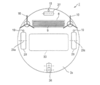
- FIG. 2 is a bottom view of the self-propelled electronic device shown in FIG. 1
- FIG. FIG. 4 is a perspective view of the drive wheel unit according to the first embodiment.
- the self-propelled electronic device 1 according to the present invention sucks air containing dust on the floor surface and exhausts the air from which dust is removed while self-propelled on the floor surface where it is installed.
- the case of the self-propelled cleaner which cleans the floor surface by doing is illustrated.
- the self-propelled electronic device 1 includes a disk-shaped housing 2, and a rotating brush 9, an auxiliary brush 10, a dust collection box 30, an electric blower (not shown), and a pair of left and right are provided inside and outside the housing 2. Components such as a control unit including drive wheels 29, rear wheels 26 and front wheels 27, and floor surface detection sensors 13 and 19 are provided.
- the self-propelled electronic device 1 is characterized by the structure of the drive wheel unit U1 including the drive wheels 29. This feature will be described in detail after the entire configuration of the self-propelled electronic device 1 is described. To do.
- the part where the front wheel 27 is arranged is the front part
- the part where the rear wheel 26 is arranged is the rear part
- the part where the dust collection box 30 is arranged is the intermediate part
- the housing 2 is supported by three wheels, that is, a pair of left and right drive wheels 29 and a rear wheel 26. That is, the front is the forward direction of the self-propelled cleaner 1, and the rear is the backward direction.
- the housing 2 opens and closes when the dust collection box 30 is taken in and out of the housing 2 and the bottom plate 2a having a suction port 6 formed at a position near the boundary with the intermediate portion in the front portion.
- a top plate 2b having a lid portion 3 at an intermediate portion, and a bottom plate 2a and a side plate 2c having an annular shape in plan view provided along the outer periphery of the top plate 2b are provided.
- the bottom plate 2a is formed with a plurality of holes for projecting the lower portions of the front wheel 27, the pair of left and right drive wheels 29 and the rear wheel 26 from the inside of the housing 2 to the outside of the top plate 2b.
- An exhaust port 7 is formed in the vicinity of the boundary.
- the side plate 2c is divided into two in the front and rear directions, and the front side portion of the side plate functions as a bumper.
- the front portion has a front storage chamber for storing a motor unit, an electric blower, an ion generator, etc. (not shown), and the intermediate portion has an intermediate storage chamber for storing the dust collection box 30.
- the rear portion has a rear storage chamber for storing a control board, a battery, a charging terminal, and the like (not shown), and has a suction passage and an exhaust passage in the vicinity of the boundary between the front portion and the intermediate portion.
- the suction port 6 is an open surface of a recess formed on the bottom surface of the housing 2 (the lower surface of the bottom plate 2a) so as to face the floor surface.
- a rotating brush 9 that rotates about a rotation axis parallel to the bottom surface of the housing 2 is provided in the recess, and the left and right sides of the recess rotate about a rotation axis that is perpendicular to the bottom surface of the housing 2.
- An auxiliary brush 10 is provided.
- the rotating brush 9 is formed by implanting a brush spirally on the outer peripheral surface of a roller that is a rotating shaft.
- the auxiliary brush 10 is formed by radially providing a bristle bundle at the lower end of the rotating shaft.
- the rotating shaft of the rotating brush 9 and the rotating shaft of the pair of auxiliary brushes 10 are pivotally attached to a part of the bottom plate 2a of the housing 2, and include a motor unit, a pulley, a belt, and the like provided in the vicinity thereof. It is independently connected through a mechanism.
- the self-propelled electronic device 1 turns when the left and right drive wheels 29 rotate forward in the same direction, move forward, move backward in the same direction, move backward, and rotate in opposite directions. For example, when the self-propelled electronic device 1 reaches the periphery of the cleaning area or collides with an obstacle on the course, the driving wheel 29 stops and the left and right driving wheels 29 rotate in opposite directions to each other. change. Thereby, the self-propelled electronic device 1 can be self-propelled while avoiding obstacles in the entire installation place or the entire desired range.
- the driving wheel unit U1 includes said drive wheels 29, and a drive wheel holder 41 for rotatably holding the drive wheel 29 to the first axis P 1 around.
- the drive wheel 29 has a wheel part (not shown) centered on the first axis P 1 and a tire part 29a attached to the outer periphery of the wheel part.
- the tire portion 29a has a plurality of rectangular convex portions 29a 1 and a plurality of concave portions 29a 2 on the outer periphery, and is circular when viewed from the direction of the first axis P 1 . That is, two tires in which the rectangular convex portions 29a 1 and the concave portions 29a 2 are alternately arranged in the circumferential direction are prepared, and the concave portion 29a 2 of the other tire is positioned beside the rectangular convex portion 29a 1 of one tire.
- a tire 29a is formed by bonding.
- the drive wheel holder 41 is attached to the housing 2 so as to be rotatable around a second axis P 2 parallel to the first axis P 1 . More specifically, the drive wheel holder 41 is a substantially shoe-sole-shaped gear case having a gear inside, and includes a front portion where the first axis P 1 is arranged and a second axis P 2. that which has a rear, and its rear portion has a rear projecting piece 41a and the second center axis P 2 become pivot shaft 41b.
- the drive wheel holder 41 is provided with a motor M capable of rotating in the forward and reverse directions on the inner surface of the rear portion thereof, and the rotational force of the motor M is transmitted via a gear and a drive shaft (not shown) on the first axis P 1. It is configured to transmit to the drive wheel 29.
- a wheel cover portion 41 d that covers the wheel portion of the drive wheel 29 is provided on the inner side surface of the front portion of the drive wheel holder 41.
- first axis P 1 is arranged substantially intermediate position in the longitudinal direction of the length of the housing 2, and the second axis P 2 is arranged behind the first axis P 1, pivot The support shaft 41b is pivotally attached to a rib in the housing 2.
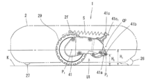
- the height H 2 of the second axis P 2 from the floor K is set lower than the height H 1 of the first axis P 1 in a state where the drive wheel 29 is in contact with the floor K.
- reference sign CP is a comparative example that is set at a position higher than the height H 1 of the first axis P 1 from the floor surface K in a state where the drive wheels 29 are in contact with the floor surface K.
- 3 shows the third horizontal axis.
- the drive wheel holder 41 is located at a position higher than the height H 2 of the second axis P 2 from the floor surface K in a state where the drive wheel 29 is in contact with the floor surface K and of the second axis P 2 .
- the elastic member S e.g., a tension spring
- the protrusion 41c has a hook 41c 1 at the upper end.
- a spring is used tensile as elastic member S, the rear end of the elastic member S is hooked on the hook portion 41c 1, the rear end of the elastic member S is provided in the housing 2 It is hooked on the hook portion 2f of the drive wheel cover 2e.
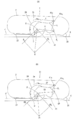
- FIGS. 5A and 5B are diagrams for explaining the step-over performance of the self-propelled electronic device, in which FIG. 5A shows the first embodiment and FIG. 5B shows a comparative example.
- the self-propelled electronic device 1 of the first embodiment configured as described above, as shown in FIG. 3 and FIG. 5 (A), between the floor surface K and the rug J laid on the floor surface K.
- the front wheel 27 rides on the stepped portion D first.
- the housing 2 is supported by the front wheel 27 and the rear wheel 26.
- a protrusion having a slope surface that slides over the corner of the stepped portion D over the bottom surface of the housing 2 may be provided, or the corner of the stepped portion D may be slidably contacted with the bottom surface. (Not shown).
- the housing 2 is supported by the protruding portion or the bottom surface of the housing and the rear wheel 26.
- the driving wheel 29 of the driving wheel unit U1 is not pressed against the floor surface K by the weight of the housing 2, but is pressed by the urging force of the elastic member S.
- the drive wheel unit U1 is pressed towards the floor surface K of the second axis P 2 as a fulcrum.
- the driving wheel 29 is pressed against the floor surface K with a pressing force R in a direction perpendicular to the line A connecting the second axis P 2 and the first axis P 1 .
- This pressing force R is expressed as a resultant force of the first component force R 1 that gets over the step portion D and the first component force R 1 and the second component force R 2 in the direction perpendicular to the first component force R 1 .
- the first component force R 1 is represented as a component force on a line connecting the contact point between the drive wheel 29 and the corner of the step portion D and the second axis P 1 .
- the height of the second axis CP is set higher than the height H 1 of the first axis P 1 (see FIG. 3).
- Other configurations in the comparative example are the same as the self-propelled electronic device 1 of the present invention.
- the drive wheel 29 is pressed against the floor surface K with a pressing force CR perpendicular to the line CA connecting the second axis CP and the first axis P 1 .
- This pressing force CR is equivalent to the pressing force R in the first embodiment shown in FIG. 5A, and includes a first component force CR 1 overcoming the step portion D and a second component in a direction perpendicular to the first component force CR 1.
- the first component force CR 1 is expressed as a component force on a line connecting the contact point between the drive wheel 29 and the corner of the step portion D and the second axis CP.
- the pressing forces R and CR are the maximum values Rmax and CRmax of the pressing forces R and CR at which the self-propelled electronic device 1 does not lift up with the self-propelled electronic device 1 installed on the floor K as shown in FIG. It is determined as appropriate in consideration of variations in the urging force F of the elastic member S.
- Embodiment 1 (FIG. 5A) is compared with the comparative example (FIG. 5B), it can be seen that there is the following difference.
- the direction of the pressing force R is slightly ahead of the direction perpendicular to the floor surface K. Leaning on.
- the direction of the pressing force CR is more than the direction perpendicular to the floor surface K. Slightly inclined backwards.
- ⁇ and C ⁇ shown in FIGS.
- the first force component R 1 of a pressing force to the corner of the step portion D of the drive wheel 29 the first embodiment it can be seen that is larger than the first force component CR 1 Comparative Example .
- the dynamic friction coefficient between the drive wheel 29 and the corner of the stepped portion D is ⁇
- the dynamic friction force is F f and CF f
- F f > CF f holds. That is, when comparing the frictional force with respect to the corner of the stepped portion D, the first embodiment is larger than the comparative example, and therefore, it can be said that the first embodiment has better step over performance than the comparative example.
- the first component force R 1 that is the pressing force to the corner of the stepped portion D of the drive wheel 29 is increased to overcome the stepped performance. so they improved, height H 2 of the second axis P 2 is set lower than the height H 1 of the first axis P 1, and the upper position of the second center axis P 2 of the drive wheels unit U1 The urging force F of the elastic member S is applied to.
- the action line L connecting the second axis P 2 and the hook portion 41c 1 in the first embodiment is longer than the line of action CL connecting the second axis CP and the hook portion 41c 1 in the comparative example, the same
- the biasing force F of the elastic member S tensile spring
- the step overcoming performance of the drive wheel 29 can be improved. Therefore, the degree of freedom of layout inside the housing 2 is improved. However, even when the center of gravity of the self-propelled electronic device 1 is in front of the first axis P 1 of the drive wheel 29, the step climbing performance is similarly improved according to this embodiment.
- FIGS. 6A and 6B show the drive wheel unit U2 in the second embodiment, where FIG. 6A is a side view and FIG. 6B is a perspective view.
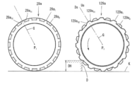
- FIG. 7 is a side view comparing the outer peripheral shape of the tire portion of each drive wheel in the first and second embodiments.
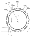
- FIG. 8 is a diagram for explaining step climbing performance due to a trapezoidal convex portion with a large inclination angle of the tire portion in the second embodiment
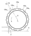
- FIG. 9 is a diagram for explaining step climbing performance due to a trapezoid convex portion with a small inclination angle of the tire portion. is there.
- FIGS. 6A and 6B the same reference numerals are given to the same elements as those in FIGS.
- the difference between the second embodiment and the first embodiment is only the drive wheel 129 of the drive wheel unit U2, and the other configurations in the second embodiment are the same as those in the first embodiment.
- the drive wheel 129 has a wheel part (not shown) and a tire part 129a attached to the outer periphery of the wheel part.
- the tire portion 129a has a plurality of the trapezoid projection portion 129a 1 and a plurality of recesses 129a 2 on the outer periphery, an uneven outer circumferential shape when viewed from the first axis P 1 direction.
- the trapezoidal convex portion 129a 1 of the tire portion 129a is inclined upstream to the upstream Us when the tire portion 129a rotates in the forward direction (arrow direction) across the radiation G from the first axis P 1. It has a surface portion 129a 11 and a downstream inclined surface portion 129a 12 on the downstream side Ds.
- the downstream inclined surface portion 129a 12 is set to have a larger inclination angle with respect to the radiation G than the upstream inclined surface portion 129a 11 .
- the upstream inclined surface portion 129a 11 is set to be parallel to the radiation G closer to the downstream inclined surface portion 129a 12 .
- the rectangular convex portion 29a 1 of the tire portion 29a of the first embodiment has vertical surface portions 29a 11 and 29a 12 substantially parallel to the radiation G on both sides of the radiation G from the first axis P 1. is doing.
- the tire portion 129a is an uneven outer circumferential shape when viewed from the first axis P 1 direction, predispose a perimeter unevenness of the tire portion 129a is to the step portion D
- the rotational force of the tire portion 129a can be effectively used for the force in the direction of riding on the step portion D.
- the downstream inclined surface portion 129a 12 of the trapezoidal convex portion 129a 1 of the tire portion 129a is set to have a large inclination angle ⁇ with respect to the radiation G, and therefore the rotational force of the tire portion 129a. Can be effectively used for the force in the direction of riding on the stepped portion D.
- the groove cutting angle is adjusted so that the tire portion 129a hits the upper surface of the stepped portion D with a flat surface (downstream inclined surface portion 129a 12 ). Further, since the inclination angle ⁇ is set large, the distance W 1 capable trapezoidal protrusion 129a1 is caught by the stepped portion D is long, trapezoidal protrusions 129a 1 is easily caught deep into the stepped portion D. Thereby, for example, it becomes effective when a self-propelled electronic device gets over a threshold with a rounded corner.
- the self-propelled cleaner according to the second embodiment further improves the step-over performance.
- the height DH gets over the stepped portion D having a height of 15 to 20 mm.
- the self-propelled electronic device 1 is a self-propelled cleaner having a cleaning function is illustrated, but the self-propelled electronic device of the present invention has a self-propelled ion having a function of generating ions. It may be a generator.
- a self-propelled electronic device includes a housing having a bottom plate, a pair of left and right drive wheel units that support the housing, and elastically biases the drive wheel unit in a direction in which the drive wheel unit protrudes downward from the bottom plate.
- a resilient member The drive wheel unit includes a drive wheel and a drive wheel holder that holds the drive wheel rotatably around the first axis, The drive wheel holder is disposed behind the first axis, and is attached to the housing so as to be rotatable around a second axis parallel to the first axis.
- the pressing force that is perpendicular to the straight line connecting the first axis and the second axis and that extends from the first axis toward the outer periphery of the drive wheel is directed forward in the traveling direction rather than the gravitational direction of the casing. As described above, the urging force of the elastic member is applied to the drive wheel unit.
- the self-propelled electronic device of the present invention may be configured as follows, or may be appropriately combined. (1) In a state where the drive wheel is in contact with the floor surface, the height of the second axis from the floor may be set lower than the height of the first axis. In this configuration, the height of the second axial center from the floor surface is set higher than the height of the first axial center, and the resilient member is positioned above the second axial center in the drive wheel unit. Compared with the case where an urging force is applied, the force with which the driving wheel presses the corner of the stepped portion while moving forward increases, so that the step-over performance of the self-propelled electronic device is improved. This effect of the present invention is particularly effective when the center of gravity of the self-propelled electronic device is at the rear.
- the drive wheel holder may have a protrusion at a position above the second axis that is attached to the elastic member and pulled toward the first axis. This is advantageous because the elastic member can be arranged in the space for arranging the drive wheel unit in the housing.
- the drive wheel may have an uneven outer peripheral shape viewed from the direction of the first axis. In this way, the unevenness on the outer periphery of the drive wheel is easily caught by the step, so the frictional resistance between the drive wheel and the step portion increases, and the step over performance of the self-propelled electronic device is further improved.
- the self-propelled electronic device may be a self-propelled electronic device having a cleaning function or a self-propelled ion generator having an ion generating function. In this way, a self-propelled electronic device or a self-propelled ion generator with improved step-over performance can be obtained.
Landscapes
- Engineering & Computer Science (AREA)
- Mechanical Engineering (AREA)
- Electric Suction Cleaners (AREA)
- Electric Vacuum Cleaner (AREA)
Abstract
Description
前記駆動輪ユニットは、駆動輪と、この駆動輪を第1軸心廻りに回転可能に保持する駆動輪ホルダとを有し、
前記駆動輪ホルダは、前記第1軸心よりも後方に配置され、前記第1軸心と平行な第2軸心廻りに回動可能として前記筐体に取り付けられており、
前記第1軸心と前記第2軸心とを結んだ直線に垂直かつ前記第1軸心から前記駆動輪の外周方向に向かう押圧力が、前記筐体の重力方向よりも進行方向前方に向くように、前記駆動輪ユニットに対して前記弾発部材の付勢力を加えるように構成された自走式電子機器が提供される。
この構成により、自走式電子機器の段差乗り越え性能が向上する。
図1は本発明の実施形態1に係る自走式電子機器の斜視図であり、図2は図1に示される自走式電子機器の底面図であり、図3は実施形態1の自走式電子機器における駆動輪ユニットの配置を説明する図であり、図4は実施形態1における駆動輪ユニットの斜視図である。
なお、実施形態1では、本発明に係る自走式電子機器1が、設置された場所の床面を自走しながら、床面上の塵埃を含む空気を吸い込み、塵埃を除去した空気を排気することにより床面上を掃除する自走式掃除機の場合を例示している。
前記駆動輪ユニットU1は、前記駆動輪29と、この駆動輪29を第1軸心P1廻りに回転可能に保持する駆動輪ホルダ41とを有する。
詳しく説明すると、駆動輪ホルダ41は、内部にギアを有する側面視略靴底形のギアケースであり、第1軸心P1が配置される前部と、第2軸心P2が配置される後部を有すると共に、その後部には後方突出片41aおよび第2軸心P2となる枢支軸41bを有している。さらに、駆動輪ホルダ41は、その後部の内側面に正逆回転可能なモータMが取り付けられており、モータMの回転力をギアおよび第1軸心P1上の図示しない駆動軸を介して駆動輪29に伝達するように構成されている。また、駆動輪ホルダ41の前部の内側面には、駆動輪29のホイール部を覆うホイールカバー部41dが設けられている。
なお、図3において、符号CPは、駆動輪29が床面Kに接地した状態において、床面Kからの第1軸心P1の高さH1よりも高い位置に設定される比較例としての第3水平軸心を示している。
実施形態1の場合、弾発部材Sとして引っ張りバネが用いられ、弾発部材Sの後端は前記フック部41c1に引っ掛けられ、弾発部材Sの後端は筐体2内に設けられた駆動輪カバー2eのフック部2fに引っ掛けられている。
このように構成された実施形態1の自走式電子機器1によれば、図3および図5(A)に示すように、床面Kと床面K上に敷かれた敷物Jとの間の段差部Dを駆動輪29が乗り越えようとする際、先に前輪27が段差部D上に乗り上げる。これにより、筐体2は前輪27と後輪26によって支持される。なお、前輪27の代わりに、筐体2の底面に段差部Dのコーナーに摺接して乗り越えるスロープ面を有する突出部を設けてもよいし、底面に段差部Dのコーナーを摺接してもよい(図示省略)。この場合、自走式電子機器1が段差部Dを乗り越える際、筐体2は、前記突出部乃至筐体底面と後輪26によって支持される。
この押圧力Rは、段差部Dを乗り越える第1分力R1と、第1分力R1と直角方向の第2分力R2との合力として表される。また、第1分力R1は、駆動輪29と段差部Dのコーナーとの接点と、第2軸心P1とを結ぶ線上の分力として表される。
比較例の場合、第2軸心CPと第1軸心P1とを結ぶ線CAに対して直角方向の押圧力CRで駆動輪29が床面Kに押し付けられる。この押圧力CRは、図5(A)の実施形態1における押圧力Rと同等であり、段差部Dを乗り越える第1分力CR1と、第1分力CR1と直角方向の第2分力CR2との合力として表される。また、第1分力CR1は、駆動輪29と段差部Dのコーナーとの接点と、第2軸心CPとを結ぶ線上の分力として表される。
この押圧力RおよびCRは、図3のように自走式電子機器1を床面Kに設置した状態で、自走式電子機器1が浮き上がらない押圧力RおよびCRの最大値RmaxおよびCRmaxと、弾発部材Sの付勢力Fのばらつきを考慮して適宜決められる。
実施形態1の場合、第2軸心P2から第1軸心P1に向かって線Aがやや上昇しているため、押圧力Rの方向は床面Kに対して垂直方向よりもやや前方に傾いている。これに対し、比較例の場合、第2軸心CPから第1軸心P1に向かって線CAがやや下降しているため、押圧力CRの方向は床面Kに対して垂直方向よりもやや後方に傾いている。
ここで、図5(A)および(B)に示されるθとCθは、
θ<Cθ
となる。前述したように、RとCRは自走式電子機器1の重量と、弾発部材Sの付勢力Fのばらつきが同程度の場合、
R=CR
とするように付勢力Fと付勢力CFを調整する。したがって、
R1=Rcos(θ)>CRcos(Cθ)=CR1
となり、R1>CR1が成り立つ。
駆動輪29と段差部Dのコーナーとの間の動摩擦係数をμ、動摩擦力をそれぞれFf、CFfとすれば、
Ff=μR1>μCR1=CFf
となり、Ff>CFfが成り立つ。つまり、段差部Dのコーナーに対する摩擦力について比較した場合、実施形態1の方が比較例よりも大きくなるので、実施形態1は比較例よりも段差乗り越え性能が優れていると言える。
このように、図5(A)に示す本発明の自走式電子機器1では、駆動輪29の段差部Dのコーナーへの押圧力である第1分力R1を大きくして段差乗り越え性能が向上するように、第2軸心P2の高さH2が第1軸心P1の高さH1よりも低く設定され、かつ駆動輪ユニットU1における第2軸心P2の上方位置に弾発部材Sの付勢力Fが加えられるように構成されている。
A×R=L×FR
CA×CR=CL×CFR
また、A=CA、R=CRであるので、
L×FR=CL×CFR
となり、L>CLであれば、FR<CFRが成り立つ。ここで、弾発部材S(引っ張りバネ)の付勢力Fが、第2軸心P2を中心とする円の正接方向に近い時、F=FR、CF=CFRと近似できる。したがって、
F<CF
となる。このように、弾発部材S(引っ張りバネ)の付勢力Fを小さくすることができるため、バネの小型化や、取り付け時の作業性を向上させることができる。
また、本実施形態によれば、自走式電子機器1の重心が駆動輪29の第1軸心P1よりも後方にある場合でも、駆動輪29の段差乗越え性能を向上させることができる。すなわち、自走式掃除機1の重心が駆動輪29の第1軸心P1よりも後方にある場合、駆動輪29が段差部Dのコーナーに到り、筐体2の駆動輪29よりも前方側が段差部Dを乗り超えたときでも、依然として重心がある筐体2の後方側が段差部Dを乗り越えていないので、駆動輪29による段差乗越え性能を向上させる必要性が強い。以上のように、本実施形態によれば、自走式電子機器1の重心が駆動輪29の第1軸心P1よりも後方にある場合でも、駆動輪29の段差乗越え性能を向上させることができるので、筐体2内部のレイアウトの自由度が向上する。但し、自走式電子機器1の重心が駆動輪29の第1軸心P1よりも前方にある場合にも、本実施形態によれば、同様に段差乗越え性能が向上するものである。
図6は実施形態2における駆動輪ユニットU2を示し、(A)は側面図であり、(B)は斜視図である。図7は実施形態1および2における各駆動輪のタイヤ部の外周形状を比較する側面図である。図8は実施形態2におけるタイヤ部の傾斜角度が大きい台形凸部による段差乗り越え性能を説明する図であり、図9はタイヤ部の傾斜角度が小さい台形凸部による段差乗り越え性能を説明する図である。なお、図6(A)および(B)において、図3および4中の要素と同様の要素には同一の符号を付している。
詳しく説明すると、駆動輪129は、図示しないホイール部と、ホイール部の外周に取り付けられたタイヤ部129aとを有する。また、タイヤ部129aは、外周に複数の台形凸部129a1と複数の凹部129a2とを有し、第1軸心P1方向から視て凹凸外周形状である。
下流側傾斜面部129a12は上流側傾斜面部129a11よりも放射線Gに対して傾斜角度が大きく設定されている。換言すると、上流側傾斜面部129a11は下流側傾斜面部129a12よりも放射線Gに対して平行に近くなるように設定されている。
これに対し、実施形態1のタイヤ部29aの矩形凸部29a1は、第1軸心P1からの放射線Gを挟んだ両側に、放射線Gと概ね平行な垂直面部29a11、29a12を有している。
これに加え、図8に示すように、タイヤ部129aの台形凸部129a1の下流側傾斜面部129a12は放射線Gに対して傾斜角度αが大きく設定されているため、タイヤ部129aの回転力を段差部Dに乗り上げる方向の力に有効に使用することができる。つまり、段差部Dの上面に、タイヤ部129aが平面(下流側傾斜面部129a12)で当たるように溝の切り込み角度を調整している。また、傾斜角度αが大きく設定されることにより、台形凸部129a1が段差部Dに引っ掛かることができる距離W1が長くなるため、台形凸部129a1が段差部Dの奥まで引っ掛かり易くなる。これにより、例えば、角部が丸くすり減った敷居を自走式電子機器が乗り越える際に有効となる。
実施形態1および2では、自走式電子機器1が、掃除機能を備える自走式掃除機の場合を例示したが、本発明の自走式電子機器はイオン発生機能を備えた自走式イオン発生装置であってもよい。
本発明の自走式電子機器は、底板を有する筐体と、前記筐体を支持する左右一対の駆動輪ユニットと、この駆動輪ユニットを前記底板から下方へ突出させる方向に弾発付勢する弾発部材とを備え、
前記駆動輪ユニットは、駆動輪と、この駆動輪を第1軸心廻りに回転可能に保持する駆動輪ホルダとを有し、
前記駆動輪ホルダは、前記第1軸心よりも後方に配置され、前記第1軸心と平行な第2軸心廻りに回動可能として前記筐体に取り付けられており、
前記第1軸心と前記第2軸心とを結んだ直線に垂直かつ前記第1軸心から前記駆動輪の外周方向に向かう押圧力が、前記筐体の重力方向よりも進行方向前方に向くように、前記駆動輪ユニットに対して前記弾発部材の付勢力を加えるように構成されている。
(1)前記駆動輪が床面に接地した状態において、床面からの前記第2軸心の高さが前記第1軸心の高さよりも低く設定されてもよい。
この構成は、床面からの前記第2軸心の高さが前記第1軸心の高さよりも高く設定され、かつ前記駆動輪ユニットにおける前記第2軸心の上方位置に前記弾発部材の付勢力が加えられる場合と比べて、前進しながら段差部のコーナーを駆動輪が押さえ付ける力が増加するため、自走式電子機器の段差乗り越え性能が向上する。本発明のこの効果は、自走式電子機器の重心が後部にある場合に特に有効である。
このようにすれば、筐体内における駆動輪ユニットを配置するスペースに弾発部材を配置することができるため、好都合となる。
このようにすれば、駆動輪外周の凹凸が段差に引っ掛かり易くなるため、駆動輪と段差部との摩擦抵抗が増加し、自走式電子機器の段差乗り越え性能がより向上する。
このようにすれば、段差乗り越え性能が向上した自走式電子機器、または自走式イオン発生装置が得られる。
2 筐体
2a 底板
29、129 駆動輪
41 駆動輪ホルダ
41c 突起部
H1、H2 高さ
K 床面
P1 第1軸心
P2 第2軸心
S 弾発部材
U 駆動輪ユニット
Claims (5)
- 底板を有する筐体と、前記筐体を支持する左右一対の駆動輪ユニットと、この駆動輪ユニットを前記底板から下方へ突出させる方向に弾発付勢する弾発部材とを備え、
前記駆動輪ユニットは、駆動輪と、この駆動輪を第1軸心廻りに回転可能に保持する駆動輪ホルダとを有し、
前記駆動輪ホルダは、前記第1軸心よりも後方に配置され、前記第1軸心と平行な第2軸心廻りに回動可能として前記筐体に取り付けられており、
前記第1軸心と前記第2軸心とを結んだ直線に垂直かつ前記第1軸心から前記駆動輪の外周方向に向かう押圧力が、前記筐体の重力方向よりも進行方向前方に向くように、前記駆動輪ユニットに対して前記弾発部材の付勢力を加えるように構成されたことを特徴とする自走式電子機器。 - 前記駆動輪が床面に接地した状態において、床面からの前記第2軸心の高さが前記第1軸心の高さよりも低く設定されている請求項1に記載の自走式電子機器。
- 前記駆動輪ホルダは、前記第2軸心の上方位置に、前記弾発部材が取り付けられて前記第1軸心側へ引き寄せられる突起部を有している請求項1または2に記載の自走式電子機器。
- 前記駆動輪は、前記第1軸心の方向から視た凹凸外周形状を有している請求項1~3のいずれか1つに記載の自走式電子機器。
- 前記自走式電子機器は、掃除機能を備える自走式掃除機、またはイオン発生機能を備えた自走式イオン発生装置である請求項1~4のいずれかに記載の自走式電子機器。
Priority Applications (2)
| Application Number | Priority Date | Filing Date | Title |
|---|---|---|---|
| US14/771,226 US9936844B2 (en) | 2013-05-30 | 2014-02-17 | Self-propelled electronic device |
| CN201490000415.2U CN204971112U (zh) | 2013-05-30 | 2014-02-17 | 自走式电子设备 |
Applications Claiming Priority (2)
| Application Number | Priority Date | Filing Date | Title |
|---|---|---|---|
| JP2013114178A JP2014230714A (ja) | 2013-05-30 | 2013-05-30 | 自走式電子機器 |
| JP2013-114178 | 2013-05-30 |
Publications (1)
| Publication Number | Publication Date |
|---|---|
| WO2014192332A1 true WO2014192332A1 (ja) | 2014-12-04 |
Family
ID=51988377
Family Applications (1)
| Application Number | Title | Priority Date | Filing Date |
|---|---|---|---|
| PCT/JP2014/053645 Ceased WO2014192332A1 (ja) | 2013-05-30 | 2014-02-17 | 自走式電子機器 |
Country Status (4)
| Country | Link |
|---|---|
| US (1) | US9936844B2 (ja) |
| JP (1) | JP2014230714A (ja) |
| CN (1) | CN204971112U (ja) |
| WO (1) | WO2014192332A1 (ja) |
Cited By (2)
| Publication number | Priority date | Publication date | Assignee | Title |
|---|---|---|---|---|
| WO2016096027A1 (en) * | 2014-12-18 | 2016-06-23 | Aktiebolaget Electrolux | Autonomous cleaning apparatus |
| CN108289579A (zh) * | 2015-11-20 | 2018-07-17 | 三星电子株式会社 | 轮组件和具有该轮组件的机器人清洁器 |
Families Citing this family (24)
| Publication number | Priority date | Publication date | Assignee | Title |
|---|---|---|---|---|
| JP6670544B2 (ja) * | 2015-01-08 | 2020-03-25 | シャープ株式会社 | 自走式電子機器 |
| JP6609410B2 (ja) * | 2015-01-08 | 2019-11-20 | シャープ株式会社 | 自走式電子機器 |
| KR102320199B1 (ko) * | 2015-04-13 | 2021-11-02 | 삼성전자주식회사 | 구동유닛 및 이를 구비하는 로봇청소기 |
| DE202017000833U1 (de) * | 2016-02-22 | 2017-03-08 | Lg Electronics Inc. | Beweglicher Roboter |
| CN109068908B (zh) * | 2016-05-11 | 2021-05-11 | 伊莱克斯公司 | 机器人清洁设备 |
| JP6656094B2 (ja) * | 2016-06-17 | 2020-03-04 | シャープ株式会社 | 自走式電子機器 |
| US10407931B2 (en) | 2016-09-02 | 2019-09-10 | Aqua Products, Inc. | Modular swimming pool cleaner |
| US10301837B2 (en) | 2016-11-04 | 2019-05-28 | Aqua Products, Inc. | Drive module for submersible autonomous vehicle |
| US9902477B1 (en) | 2016-11-04 | 2018-02-27 | Aqua Products, Inc. | Drive module for submersible autonomous vehicle |
| US10239370B2 (en) * | 2017-08-02 | 2019-03-26 | AI Incorporated | Wheel suspension system |
| CN107440614B (zh) * | 2017-08-07 | 2019-12-20 | 江苏美的清洁电器股份有限公司 | 吸尘器 |
| CN107361693A (zh) * | 2017-08-28 | 2017-11-21 | 合肥立腾信息科技有限责任公司 | 一种智能扫地机 |
| JP6928514B2 (ja) * | 2017-08-31 | 2021-09-01 | 株式会社マキタ | ロボット集塵機及び自走式機器 |
| CN107595213B (zh) * | 2017-10-25 | 2024-10-22 | 美智纵横科技有限责任公司 | 驱动轮结构及清洁装置 |
| JP6689810B2 (ja) * | 2017-10-26 | 2020-04-28 | 日立グローバルライフソリューションズ株式会社 | 自律走行型掃除機 |
| CN110115549B (zh) * | 2018-02-05 | 2025-02-21 | 科沃斯机器人股份有限公司 | 自移动机器人及其行走方法 |
| CN109131620B (zh) * | 2018-08-31 | 2024-06-18 | 深圳银星智能集团股份有限公司 | 移动装置 |
| KR102662323B1 (ko) * | 2019-10-02 | 2024-04-30 | 엘지전자 주식회사 | 로봇 청소기 |
| CN110623607A (zh) * | 2019-10-18 | 2019-12-31 | 微思机器人(深圳)有限公司 | 滚轮装置及扫地机 |
| CN111973083B (zh) * | 2020-08-27 | 2025-11-18 | 苏州三六零机器人科技有限公司 | 扫地机 |
| TWD219796S (zh) * | 2020-10-15 | 2022-07-11 | 大陸商北京石頭世紀科技股份有限公司 | 清潔機器人 |
| CN217072349U (zh) * | 2021-04-09 | 2022-07-29 | 美智纵横科技有限责任公司 | 一种自移动机器人 |
| CN114098565B (zh) * | 2021-04-14 | 2023-05-16 | 曲阜信多达智能科技有限公司 | 清洁机的控制方法 |
| US20250089958A1 (en) * | 2023-09-18 | 2025-03-20 | Irobot Corporation | Mobile cleaning robot suspension |
Citations (4)
| Publication number | Priority date | Publication date | Assignee | Title |
|---|---|---|---|---|
| JP2003033310A (ja) * | 2001-07-19 | 2003-02-04 | Toshiba Tec Corp | 走行車 |
| JP2008220882A (ja) * | 2007-03-16 | 2008-09-25 | Sanyo Electric Co Ltd | 自走車 |
| JP2013045463A (ja) * | 2011-08-22 | 2013-03-04 | Samsung Electronics Co Ltd | ロボット掃除機及びその制御方法 |
| JP2013059624A (ja) * | 2011-09-09 | 2013-04-04 | Dyson Technology Ltd | 自律表面処理電気器具 |
Family Cites Families (7)
| Publication number | Priority date | Publication date | Assignee | Title |
|---|---|---|---|---|
| KR101812021B1 (ko) * | 2011-09-30 | 2017-12-27 | 삼성전자주식회사 | 로봇청소기 |
| JP4838978B2 (ja) | 2002-12-16 | 2011-12-14 | アイロボット コーポレイション | 自律的床清掃ロボット |
| JP4277214B2 (ja) * | 2004-11-30 | 2009-06-10 | 日立アプライアンス株式会社 | 自走式掃除機 |
| KR100761997B1 (ko) * | 2005-12-29 | 2007-09-28 | 에이스로봇 주식회사 | 청소로봇용 휠 어셈블리 |
| KR101523980B1 (ko) * | 2011-01-18 | 2015-06-01 | 삼성전자 주식회사 | 로봇 청소기 |
| KR101311295B1 (ko) * | 2011-07-13 | 2013-09-25 | 주식회사 유진로봇 | 이동 로봇의 휠 조립체 |
| GB2494443B (en) * | 2011-09-09 | 2013-08-07 | Dyson Technology Ltd | Autonomous surface treating appliance |
-
2013
- 2013-05-30 JP JP2013114178A patent/JP2014230714A/ja active Pending
-
2014
- 2014-02-17 US US14/771,226 patent/US9936844B2/en not_active Expired - Fee Related
- 2014-02-17 CN CN201490000415.2U patent/CN204971112U/zh not_active Expired - Fee Related
- 2014-02-17 WO PCT/JP2014/053645 patent/WO2014192332A1/ja not_active Ceased
Patent Citations (4)
| Publication number | Priority date | Publication date | Assignee | Title |
|---|---|---|---|---|
| JP2003033310A (ja) * | 2001-07-19 | 2003-02-04 | Toshiba Tec Corp | 走行車 |
| JP2008220882A (ja) * | 2007-03-16 | 2008-09-25 | Sanyo Electric Co Ltd | 自走車 |
| JP2013045463A (ja) * | 2011-08-22 | 2013-03-04 | Samsung Electronics Co Ltd | ロボット掃除機及びその制御方法 |
| JP2013059624A (ja) * | 2011-09-09 | 2013-04-04 | Dyson Technology Ltd | 自律表面処理電気器具 |
Cited By (7)
| Publication number | Priority date | Publication date | Assignee | Title |
|---|---|---|---|---|
| WO2016096027A1 (en) * | 2014-12-18 | 2016-06-23 | Aktiebolaget Electrolux | Autonomous cleaning apparatus |
| CN108289579A (zh) * | 2015-11-20 | 2018-07-17 | 三星电子株式会社 | 轮组件和具有该轮组件的机器人清洁器 |
| EP3342322A4 (en) * | 2015-11-20 | 2018-11-14 | Samsung Electronics Co., Ltd. | Wheel assembly and robot cleaner having same |
| US20190090703A1 (en) * | 2015-11-20 | 2019-03-28 | Samsung Electronics Co., Ltd. | Wheel assembly and robot cleaner having same |
| US11083353B2 (en) | 2015-11-20 | 2021-08-10 | Samsung Electronics Co., Ltd. | Wheel assembly and robot cleaner having same |
| AU2016356448B2 (en) * | 2015-11-20 | 2022-03-10 | Samsung Electronics Co., Ltd. | Wheel assembly and robot cleaner having same |
| US11627850B2 (en) | 2015-11-20 | 2023-04-18 | Samsung Electronics Co., Ltd. | Wheel assembly and robot cleaner having same |
Also Published As
| Publication number | Publication date |
|---|---|
| CN204971112U (zh) | 2016-01-20 |
| US9936844B2 (en) | 2018-04-10 |
| JP2014230714A (ja) | 2014-12-11 |
| US20160015232A1 (en) | 2016-01-21 |
Similar Documents
| Publication | Publication Date | Title |
|---|---|---|
| WO2014192332A1 (ja) | 自走式電子機器 | |
| JP7743636B2 (ja) | 自動清掃装置およびシステム | |
| JP5937877B2 (ja) | 自走式掃除機 | |
| CN102525351B (zh) | 自主式清洁装置 | |
| US7827654B2 (en) | Self-traveling cleaner | |
| JP6774736B2 (ja) | 自走式電子機器 | |
| CN110881903A (zh) | 自主行走式电动吸尘器 | |
| KR20130037448A (ko) | 로봇청소기 | |
| JP6928514B2 (ja) | ロボット集塵機及び自走式機器 | |
| CN112230229A (zh) | 光学传感器及机器人集尘机 | |
| KR20130109068A (ko) | 전기 청소기 | |
| JP2015134297A (ja) | 自走式電子機器 | |
| CN113576312B (zh) | 一种自主清洁设备及其降噪风道装置 | |
| JP6140523B2 (ja) | 補助ブラシの取付構造およびそれを備えた自走式掃除機 | |
| JPWO2019097735A1 (ja) | 自走式電子機器の車輪支持構造 | |
| CN107928542A (zh) | 自行式电动吸尘器以及自行式电动吸尘器套件 | |
| JP2017140475A (ja) | 自走式電子機器 | |
| KR102373832B1 (ko) | 로봇 청소기 | |
| CN106604670B (zh) | 自走式电子设备 | |
| JP6140335B2 (ja) | 自走式掃除機 | |
| JP7145040B2 (ja) | ロボット集塵機 | |
| JP6349009B2 (ja) | 自走式掃除機 | |
| KR20250068298A (ko) | 로봇 청소기 | |
| KR20120057123A (ko) | 로봇 청소기 |
Legal Events
| Date | Code | Title | Description |
|---|---|---|---|
| WWE | Wipo information: entry into national phase |
Ref document number: 201490000415.2 Country of ref document: CN |
|
| 121 | Ep: the epo has been informed by wipo that ep was designated in this application |
Ref document number: 14805013 Country of ref document: EP Kind code of ref document: A1 |
|
| WWE | Wipo information: entry into national phase |
Ref document number: 14771226 Country of ref document: US |
|
| NENP | Non-entry into the national phase |
Ref country code: DE |
|
| 122 | Ep: pct application non-entry in european phase |
Ref document number: 14805013 Country of ref document: EP Kind code of ref document: A1 |