WO2014192172A1 - 作業車両 - Google Patents
作業車両 Download PDFInfo
- Publication number
- WO2014192172A1 WO2014192172A1 PCT/JP2013/075360 JP2013075360W WO2014192172A1 WO 2014192172 A1 WO2014192172 A1 WO 2014192172A1 JP 2013075360 W JP2013075360 W JP 2013075360W WO 2014192172 A1 WO2014192172 A1 WO 2014192172A1
- Authority
- WO
- WIPO (PCT)
- Prior art keywords
- fan
- engine
- idling stop
- hydraulic
- work vehicle
- Prior art date
- Legal status (The legal status is an assumption and is not a legal conclusion. Google has not performed a legal analysis and makes no representation as to the accuracy of the status listed.)
- Ceased
Links
Images





Classifications
-
- E—FIXED CONSTRUCTIONS
- E02—HYDRAULIC ENGINEERING; FOUNDATIONS; SOIL SHIFTING
- E02F—DREDGING; SOIL-SHIFTING
- E02F9/00—Component parts of dredgers or soil-shifting machines, not restricted to one of the kinds covered by groups E02F3/00 - E02F7/00
- E02F9/20—Drives; Control devices
- E02F9/22—Hydraulic or pneumatic drives
- E02F9/226—Safety arrangements, e.g. hydraulic driven fans, preventing cavitation, leakage, overheating
-
- E—FIXED CONSTRUCTIONS
- E02—HYDRAULIC ENGINEERING; FOUNDATIONS; SOIL SHIFTING
- E02F—DREDGING; SOIL-SHIFTING
- E02F9/00—Component parts of dredgers or soil-shifting machines, not restricted to one of the kinds covered by groups E02F3/00 - E02F7/00
- E02F9/08—Superstructures; Supports for superstructures
- E02F9/0858—Arrangement of component parts installed on superstructures not otherwise provided for, e.g. electric components, fenders, air-conditioning units
- E02F9/0891—Lids or bonnets or doors or details thereof
-
- E—FIXED CONSTRUCTIONS
- E02—HYDRAULIC ENGINEERING; FOUNDATIONS; SOIL SHIFTING
- E02F—DREDGING; SOIL-SHIFTING
- E02F9/00—Component parts of dredgers or soil-shifting machines, not restricted to one of the kinds covered by groups E02F3/00 - E02F7/00
- E02F9/20—Drives; Control devices
- E02F9/2058—Electric or electro-mechanical or mechanical control devices of vehicle sub-units
- E02F9/2062—Control of propulsion units
- E02F9/2066—Control of propulsion units of the type combustion engines
-
- E—FIXED CONSTRUCTIONS
- E02—HYDRAULIC ENGINEERING; FOUNDATIONS; SOIL SHIFTING
- E02F—DREDGING; SOIL-SHIFTING
- E02F9/00—Component parts of dredgers or soil-shifting machines, not restricted to one of the kinds covered by groups E02F3/00 - E02F7/00
- E02F9/20—Drives; Control devices
- E02F9/22—Hydraulic or pneumatic drives
- E02F9/2246—Control of prime movers, e.g. depending on the hydraulic load of work tools
-
- E—FIXED CONSTRUCTIONS
- E02—HYDRAULIC ENGINEERING; FOUNDATIONS; SOIL SHIFTING
- E02F—DREDGING; SOIL-SHIFTING
- E02F9/00—Component parts of dredgers or soil-shifting machines, not restricted to one of the kinds covered by groups E02F3/00 - E02F7/00
- E02F9/20—Drives; Control devices
- E02F9/22—Hydraulic or pneumatic drives
- E02F9/2278—Hydraulic circuits
- E02F9/2292—Systems with two or more pumps
-
- E—FIXED CONSTRUCTIONS
- E02—HYDRAULIC ENGINEERING; FOUNDATIONS; SOIL SHIFTING
- E02F—DREDGING; SOIL-SHIFTING
- E02F9/00—Component parts of dredgers or soil-shifting machines, not restricted to one of the kinds covered by groups E02F3/00 - E02F7/00
- E02F9/20—Drives; Control devices
- E02F9/22—Hydraulic or pneumatic drives
- E02F9/2278—Hydraulic circuits
- E02F9/2296—Systems with a variable displacement pump
-
- F—MECHANICAL ENGINEERING; LIGHTING; HEATING; WEAPONS; BLASTING
- F01—MACHINES OR ENGINES IN GENERAL; ENGINE PLANTS IN GENERAL; STEAM ENGINES
- F01P—COOLING OF MACHINES OR ENGINES IN GENERAL; COOLING OF INTERNAL-COMBUSTION ENGINES
- F01P1/00—Air cooling
- F01P1/06—Arrangements for cooling other engine or machine parts
-
- F—MECHANICAL ENGINEERING; LIGHTING; HEATING; WEAPONS; BLASTING
- F01—MACHINES OR ENGINES IN GENERAL; ENGINE PLANTS IN GENERAL; STEAM ENGINES
- F01P—COOLING OF MACHINES OR ENGINES IN GENERAL; COOLING OF INTERNAL-COMBUSTION ENGINES
- F01P5/00—Pumping cooling-air or liquid coolants
- F01P5/02—Pumping cooling-air; Arrangements of cooling-air pumps, e.g. fans or blowers
- F01P5/04—Pump-driving arrangements
-
- F—MECHANICAL ENGINEERING; LIGHTING; HEATING; WEAPONS; BLASTING
- F01—MACHINES OR ENGINES IN GENERAL; ENGINE PLANTS IN GENERAL; STEAM ENGINES
- F01P—COOLING OF MACHINES OR ENGINES IN GENERAL; COOLING OF INTERNAL-COMBUSTION ENGINES
- F01P5/00—Pumping cooling-air or liquid coolants
- F01P5/02—Pumping cooling-air; Arrangements of cooling-air pumps, e.g. fans or blowers
- F01P5/04—Pump-driving arrangements
- F01P5/043—Pump reversing arrangements
-
- F—MECHANICAL ENGINEERING; LIGHTING; HEATING; WEAPONS; BLASTING
- F02—COMBUSTION ENGINES; HOT-GAS OR COMBUSTION-PRODUCT ENGINE PLANTS
- F02D—CONTROLLING COMBUSTION ENGINES
- F02D29/00—Controlling engines, such controlling being peculiar to the devices driven thereby, the devices being other than parts or accessories essential to engine operation, e.g. controlling of engines by signals external thereto
- F02D29/02—Controlling engines, such controlling being peculiar to the devices driven thereby, the devices being other than parts or accessories essential to engine operation, e.g. controlling of engines by signals external thereto peculiar to engines driving vehicles; peculiar to engines driving variable pitch propellers
-
- F—MECHANICAL ENGINEERING; LIGHTING; HEATING; WEAPONS; BLASTING
- F15—FLUID-PRESSURE ACTUATORS; HYDRAULICS OR PNEUMATICS IN GENERAL
- F15B—SYSTEMS ACTING BY MEANS OF FLUIDS IN GENERAL; FLUID-PRESSURE ACTUATORS, e.g. SERVOMOTORS; DETAILS OF FLUID-PRESSURE SYSTEMS, NOT OTHERWISE PROVIDED FOR
- F15B11/00—Servomotor systems without provision for follow-up action; Circuits therefor
- F15B11/08—Servomotor systems without provision for follow-up action; Circuits therefor with only one servomotor
-
- E—FIXED CONSTRUCTIONS
- E02—HYDRAULIC ENGINEERING; FOUNDATIONS; SOIL SHIFTING
- E02F—DREDGING; SOIL-SHIFTING
- E02F3/00—Dredgers; Soil-shifting machines
- E02F3/04—Dredgers; Soil-shifting machines mechanically-driven
- E02F3/76—Graders, bulldozers, or the like with scraper plates or ploughshare-like elements; Levelling scarifying devices
- E02F3/7604—Combinations of scraper blades with soil loosening tools working independently of scraper blades
-
- E—FIXED CONSTRUCTIONS
- E02—HYDRAULIC ENGINEERING; FOUNDATIONS; SOIL SHIFTING
- E02F—DREDGING; SOIL-SHIFTING
- E02F3/00—Dredgers; Soil-shifting machines
- E02F3/04—Dredgers; Soil-shifting machines mechanically-driven
- E02F3/76—Graders, bulldozers, or the like with scraper plates or ploughshare-like elements; Levelling scarifying devices
- E02F3/7609—Scraper blade mounted forwardly of the tractor on a pair of pivoting arms which are linked to the sides of the tractor, e.g. bulldozers
-
- E—FIXED CONSTRUCTIONS
- E02—HYDRAULIC ENGINEERING; FOUNDATIONS; SOIL SHIFTING
- E02F—DREDGING; SOIL-SHIFTING
- E02F9/00—Component parts of dredgers or soil-shifting machines, not restricted to one of the kinds covered by groups E02F3/00 - E02F7/00
- E02F9/08—Superstructures; Supports for superstructures
- E02F9/0858—Arrangement of component parts installed on superstructures not otherwise provided for, e.g. electric components, fenders, air-conditioning units
- E02F9/0866—Engine compartment, e.g. heat exchangers, exhaust filters, cooling devices, silencers, mufflers, position of hydraulic pumps in the engine compartment
-
- F—MECHANICAL ENGINEERING; LIGHTING; HEATING; WEAPONS; BLASTING
- F01—MACHINES OR ENGINES IN GENERAL; ENGINE PLANTS IN GENERAL; STEAM ENGINES
- F01P—COOLING OF MACHINES OR ENGINES IN GENERAL; COOLING OF INTERNAL-COMBUSTION ENGINES
- F01P11/00—Component parts, details, or accessories not provided for in, or of interest apart from, groups F01P1/00 - F01P9/00
- F01P11/06—Cleaning; Combating corrosion
- F01P2011/063—Cleaning
-
- F—MECHANICAL ENGINEERING; LIGHTING; HEATING; WEAPONS; BLASTING
- F02—COMBUSTION ENGINES; HOT-GAS OR COMBUSTION-PRODUCT ENGINE PLANTS
- F02D—CONTROLLING COMBUSTION ENGINES
- F02D29/00—Controlling engines, such controlling being peculiar to the devices driven thereby, the devices being other than parts or accessories essential to engine operation, e.g. controlling of engines by signals external thereto
- F02D29/04—Controlling engines, such controlling being peculiar to the devices driven thereby, the devices being other than parts or accessories essential to engine operation, e.g. controlling of engines by signals external thereto peculiar to engines driving pumps
-
- F—MECHANICAL ENGINEERING; LIGHTING; HEATING; WEAPONS; BLASTING
- F02—COMBUSTION ENGINES; HOT-GAS OR COMBUSTION-PRODUCT ENGINE PLANTS
- F02N—STARTING OF COMBUSTION ENGINES; STARTING AIDS FOR SUCH ENGINES, NOT OTHERWISE PROVIDED FOR
- F02N11/00—Starting of engines by means of electric motors
- F02N11/08—Circuits specially adapted for starting of engines
- F02N11/0814—Circuits specially adapted for starting of engines comprising means for controlling automatic idle-start-stop
- F02N11/0818—Conditions for starting or stopping the engine or for deactivating the idle-start-stop mode
-
- F—MECHANICAL ENGINEERING; LIGHTING; HEATING; WEAPONS; BLASTING
- F15—FLUID-PRESSURE ACTUATORS; HYDRAULICS OR PNEUMATICS IN GENERAL
- F15B—SYSTEMS ACTING BY MEANS OF FLUIDS IN GENERAL; FLUID-PRESSURE ACTUATORS, e.g. SERVOMOTORS; DETAILS OF FLUID-PRESSURE SYSTEMS, NOT OTHERWISE PROVIDED FOR
- F15B2211/00—Circuits for servomotor systems
- F15B2211/60—Circuit components or control therefor
- F15B2211/66—Temperature control methods
Definitions
- the present invention relates to a work vehicle, and more particularly to a work vehicle having a cooling core.
- a working vehicle such as a bulldozer
- a working machine such as a blade
- a hydraulic pump driven by an engine a fan driven by hydraulic oil discharged from the hydraulic pump
- cooling that flows to the engine by the flow of air generated by the fan
- the cooling core include a radiator or an oil cooler.
- the idling stop function is a function that automatically stops the engine when the idling state of the work vehicle continues for a predetermined time.
- the idling state means a state where the work vehicle stands by while the engine is operating.
- Japanese Patent Laid-Open No. 2003-65097 proposes a configuration in which an idling engine is stopped when a non-operating state of a work vehicle continues for a predetermined time.
- the above publication shows that the engine in the idling state is stopped when the non-operating state of the work vehicle continues for a predetermined time, but during the cleaning operation of the cooling core that rotates the fan in the reverse direction.
- the fan driven by the engine is also stopped, so that the cooling core cleaning operation is forcibly interrupted.
- This invention was made in order to solve the above problems, and it aims at providing the work vehicle which can perform the cleaning operation
- a work vehicle includes an engine, a cooling core, a fan, a hydraulic drive unit, and an idling stop execution unit.
- the cooling core is mounted on the work vehicle.
- the fan blows air to the cooling core and can rotate forward and backward.
- the hydraulic drive unit drives the fan by driving the engine.
- the idling stop execution unit stops the engine based on the rotational state and idling state of the fan by the hydraulic drive unit.
- the idling stop execution unit stops the engine when the rotation of the fan is normal rotation and the idling state continues for a predetermined time, and does not stop the engine when the rotation of the fan is reverse rotation.
- the engine is stopped when the rotation of the fan is normal and the idling state continues for a predetermined time, and the engine is not stopped when the rotation of the fan is reverse.
- the engine does not stop when the fan rotates in the reverse direction, so the engine is prohibited from being stopped during cleaning of the cooling core that removes clogs that are clogged by airflow in the reverse direction to the cooling core.
- the cooling core can be effectively cleaned.
- the work vehicle further includes a driver's cab and an operation panel.
- the operation panel is provided in the driver's cab and accepts an instruction for reverse rotation of the fan by the operator.
- the hydraulic drive unit reversely drives the fan when receiving an instruction for reverse rotation of the fan to the operation panel.
- the operation panel is provided in the driver's cab, and an instruction for reverse rotation of the fan by the operator is received via the operation panel. Therefore, the operator can easily and easily instruct execution of the cleaning function in which the rotation of the fan is the reverse rotation.
- the hydraulic drive unit includes a hydraulic motor, a hydraulic pump, a switching valve, and an adjustment unit.
- the hydraulic motor drives the fan.
- the hydraulic pump supplies hydraulic oil to the hydraulic motor by driving the engine.
- the switching valve switches a path through which hydraulic oil flows to the hydraulic motor.
- the adjustment unit adjusts the amount of hydraulic oil supplied from the hydraulic pump to the hydraulic motor.
- the rotational speed of the forward / reverse rotation of the fan can be varied according to the amount of hydraulic oil supplied from the hydraulic pump to the hydraulic motor.
- the adjustment unit adjusts the amount of hydraulic oil supplied from the hydraulic pump to the hydraulic motor so that the rotational speed of the fan becomes the maximum rotational speed when the fan rotates in the reverse direction.
- the supply amount of the hydraulic oil is adjusted so that the rotation speed of the fan becomes the maximum rotation speed when the fan rotates in the reverse direction.
- the work vehicle further includes a detection unit.
- the detection unit detects an operation state of the work vehicle.
- the idling stop execution unit stops the engine when the detection unit detects that the operation state of the work vehicle is a non-operation state, and the fan rotation is normal rotation and the idling state continues for a predetermined time. When the fan rotates in the reverse direction, the engine is not stopped.
- the fan rotation is normal rotation, and the idling state continues for a predetermined time, the engine is stopped and the fan rotation is reverse rotation. In that case, do not stop the engine. As a result, the engine does not stop in the operation state in which the work vehicle is operated, so that the work vehicle can be operated smoothly.
- the work vehicle further includes a sensor for detecting the temperature of engine coolant or hydraulic oil.
- the idling stop execution unit stops the engine when the temperature of the engine coolant or hydraulic oil detected by the sensor is within a predetermined range, the fan is rotating in the normal direction, and the idling state continues for a predetermined time. Stop and do not stop the engine if the fan is rotating in reverse.
- the engine is stopped when the temperature of the engine coolant or hydraulic oil detected by the sensor is within a predetermined range, the fan is rotating forward, and the idling state continues for a predetermined time. If the fan rotates in the reverse direction, the engine is not stopped. As a result, the engine does not stop when the temperature of the cooling water or hydraulic oil of the engine of the work vehicle is outside the predetermined range, so that the engine is not stopped when it is not desirable to stop the engine whose temperature is outside the predetermined range. It is possible to operate the work vehicle smoothly.
- the work vehicle further includes a cover body provided to cover the engine, the cooling core, and the fan.
- the cover body includes a side cover that can be opened when the fan rotates in the reverse direction with respect to the engine, the cooling core, and at least one side of the fan.
- the cover body includes the engine, the cooling core, and the side cover that can be opened when the fan is reversely rotated with respect to at least one side of the fan.
- the work vehicle of the present invention can effectively perform the cleaning operation of the cooling core.
- FIG. 1 is a side view of a bulldozer 1.
- 2 is a perspective view showing an internal configuration of a cab 6;
- FIG. 1 is a circuit diagram of a hydraulic drive system of a bulldozer 1.
- FIG. It is a figure explaining arrangement
- FIG. 7 is a flowchart of an idling stop control process of an idling stop control unit 51. It is a figure explaining the form of the side cover provided in the bulldozer.
- a bulldozer will be mainly described as an example of a work vehicle.
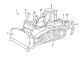
- FIG. 1 is a side view of the bulldozer 1.
- the bulldozer 1 includes a traveling body 2, a vehicle body 3, a blade 7, a ripper 8, and a cab 6.
- the vehicle body 3 is provided on the upper part of the traveling body 2.
- the traveling body 2 is provided in a lower part of the vehicle body 3 so as to be able to travel, and can travel on rough terrain by rotating a pair of endless crawler belts.
- the vehicle body 3 is equipped with an engine 4 and a cooling core 10.
- the engine 4 is provided in an engine room provided in the front portion of the vehicle body 3.
- the engine 4 is a diesel engine as an example.
- the cooling core 10 includes at least one of a radiator used for cooling the cooling water of the engine 4 and an oil cooler for cooling the hydraulic oil.
- the vehicle body 3 includes a cover body 5, and the cover body 5 is provided so as to cover the engine 4, the cooling core 10, and a fan that blows air to the cooling core 10 described later. As will be described later, a part of the cover body 5 has a side cover that can be opened and closed.
- the cab 6 is provided near the center rear portion of the vehicle body 3.
- the blade 7 is mounted as a working machine in front of the vehicle body 3 and is a working machine for scraping the ground and carrying the earth and sand, and is driven by a hydraulic cylinder 7a according to an operation of a blade operating lever described later.
- the ripper 8 is mounted as a working machine behind the vehicle body 3 and pierces a rock or the like at the tip end protruding substantially vertically downward, and performs cutting and pulverization by the traction force of the traveling body 2. Similar to the blade 7, the ripper 8 is driven by a hydraulic cylinder 8a in accordance with an operation of a ripper operation lever described later. Generally, a lift cylinder that moves the ripper 8 up and down and a tilt cylinder that moves the tip of the ripper 8 back and forth are provided.
- the driver's cab 6 is equipped with an operator seat (driver's seat) for an operator (operator) to sit, a lever, a pedal, and instruments for various operations.
- FIG. 2 is a perspective view showing the internal configuration of the cab 6.
- the cab 6 includes an operator seat 19, a right operation device 24, a left operation device 27, an operation panel 100, a lock lever 29, and the like.
- the operator seat 19 is a seat on which an operator (operator) who gets in and out of the cab sits and performs a driving operation, and is installed so as to be slidable back and forth. Further, the operator seat 19 is installed in a rotatable state in order to improve operability when the operator operates the ripper 8 or the like while looking back.
- An operation panel 100 that can be operated while an operator (operator) is seated is installed in front of the operator seat 19. An operator can perform various settings of the bulldozer 1 by operating the operation panel 100.
- the operation panel 100 is provided so as to notify the operator of the engine state of the bulldozer and accept setting instructions regarding various operations.
- the engine state is, for example, engine cooling water temperature, hydraulic oil temperature, fuel remaining amount, and the like.
- the various operations include settings related to an idling stop function, instructions related to a cooling function for the cooling core, and the like.
- the right operation device 24 is arranged on the right side of the operator seat 19 when viewed from the operator seated on the operator seat 19. On the upper surface of the right operating device 24, a blade operating lever 25, a ripper operating lever 26, and the like are provided.
- the left operation device 27 is arranged on the left side of the operator seat 19 as viewed from the operator seated on the operator seat 19.
- a travel operation lever 28 and the like are provided on the upper surface of the left operation device 27.
- the travel operation lever 28 is swung in the front-rear direction and the left-right direction when the forward direction of the vehicle body is the front, and a steering operation is performed.
- the lock lever 29 is provided in the vicinity of the traveling operation lever 28 and the blade operation lever 25, respectively.
- lock levers 29 provided on the left and right are connected, and by moving one up and down, the other moves in the same manner.
- the lock lever 29 is for stopping functions such as operation of the work implement (blade 7 and ripper 8) and traveling of the traveling body 2. That is, the operation of the work implement or the like can be locked (restricted) by performing an operation (here, a pulling-down operation of the lock lever) to position the lock lever 29 in a lowered state. In a state where the movement of the work implement or the like is locked by the lock lever 29, even if the operator operates the blade operation lever 25 or the travel operation lever 28 or the like, the work implement or the like does not operate.
- FIG. 3 is a circuit diagram of the hydraulic drive system of the bulldozer 1.
- the drive system of the bulldozer 1 includes a blade 7, an engine 4, a water pump 4a, a water jacket 4c, a radiator 11, hydraulic pumps 14 and 43, an electromagnetic switching valve 15, an oil pressure switch, Motor 41, fan 13, oil cooler 12, pipelines 4b, 11a, 12a, 14a, 15a, 31a, 32a, 35a, check valve 18, hydraulic oil tank 17, hydraulic oil temperature sensor 22, Controller 20, servo valves 14b and 31b, electromagnetic proportional valve 14c, pressure reducing valve 48, control valve 47, hydraulic cylinder 7a, pilot pressure operating valve 49, blade operating lever 25, load sensing valve 31c, The cooling water temperature sensor 21, the engine rotation sensor 23, and the operation panel 100 are included.
- the engine 4 drives variable displacement hydraulic pumps 14 and 43.
- the hydraulic oil discharged from the hydraulic pump 14 flows into the input port of the electromagnetic switching valve 15 via the pipe line 14 a and is supplied to the fixed displacement hydraulic motor 41 by the electromagnetic switching valve 15.
- the fan 13 is rotatably attached to the output rotation shaft of the hydraulic motor 41.
- the return oil from the hydraulic motor 41 enters the oil cooler 12 via the electromagnetic switching valve 15, the pipe line 15a and the pipe line 32a, is cooled by the oil cooler 12, and returns to the hydraulic oil tank 17 through the pipe line 12a.
- a circulation circuit is formed.
- a check valve 18 for circulating oil of the hydraulic motor 41 that rotates by inertia when the hydraulic pump 14 and the hydraulic motor 41 are stopped is connected between the pipeline 14a and the pipeline 15a.
- the hydraulic oil tank 17 is provided with a hydraulic oil temperature sensor 22 that detects the temperature of the hydraulic oil.
- a detection signal of the hydraulic oil temperature sensor 22 is input to the controller 20.
- the hydraulic pump 14 changes the discharge amount by controlling the output capacity by the operation of the servo valve 14b.
- the rotation speed of the fan 13 is controlled by the change in the variable discharge amount, that is, the supply amount of hydraulic oil.
- the electromagnetic proportional valve 14c receives the control pressure P1 from the pressure reducing valve 48, and outputs a pilot pressure corresponding to the command current value I1 from the controller 20 to the servo valve 14b.
- the servo valve 14b is a hydraulic pump based on this pilot pressure. The tilt angle of the 14 swash plate is controlled.
- the electromagnetic switching valve 15 is a two-position valve, and is switched to the A position and the B position by a switching signal I2 from the controller 20 to control the direction of the output flow rate, so that the hydraulic motor 41, that is, the fan 13 can be rotated forward and backward. is doing.
- the fan 13 rotates forward when the electromagnetic switching valve 15 is at the A position, and the fan 13 rotates reversely when the electromagnetic switching valve 15 is at the B position.
- variable displacement hydraulic pump 43 is driven by the engine 4 for the working machine shown in FIG. 1 (here, the blade 7 is representative).
- the hydraulic oil discharged from the hydraulic pump 43 flows into the control valve 47 through the pipe line 31a and is supplied to the hydraulic cylinder 7a by the operation of the control valve 47.
- the vertical movement of the blade 7 is driven by the expansion and contraction of the hydraulic cylinder 7a.
- the return oil from the hydraulic cylinder 7a enters the oil cooler 12 through the control valve 47 and the pipe line 32a, is cooled by the oil cooler 12, and forms a circulation circuit that returns to the hydraulic oil tank 17 through the pipe line 12a. is doing.
- the pilot pressure operation valve 49 receives the control pressure P1 from the pressure reducing valve 48 that is branched from the pipe 31a, and outputs a pilot pressure P2 corresponding to the operation amount of the blade operation lever 25.
- the control valve 47 supplies the hydraulic oil 7a with an amount of discharge oil corresponding to the pilot pressure P2 from the pilot pressure operation valve 49.
- the discharge amount is controlled by the operation of the servo valve 31b, and the speed of the hydraulic cylinder 7a is controlled by the variable discharge amount.
- the load sensing valve (LS valve) 31c receives the load pressure P3 from the control valve 47 and the control pressure P1 from the pressure reducing valve 48 and outputs a pilot pressure to the servo valve 31b.
- the servo valve 31b is based on this pilot pressure.
- the tilt angle of the swash plate of the hydraulic pump 43 is controlled.
- the hydraulic cylinder 7a is expanded and contracted by the blade operating lever 25 and the blade 7 is driven.
- the hydraulic cylinder 8a is expanded and contracted by the ripper operating lever 26 according to a similar method. The ripper 8 is driven.
- the engine 4 is provided with an engine rotation sensor 23 for detecting the number of revolutions, and the pipe 4b provided at the inlet of the radiator 11 is provided with a cooling water temperature sensor 21 for detecting the temperature of the cooling water of the engine 4. Detection signals of the respective sensors are input to the controller 20.
- the controller 20 is a controller that controls the entire bulldozer 1 and includes a CPU (Central Processing Unit), a nonvolatile memory, a timer, and the like. Moreover, it has the memory
- CPU Central Processing Unit
- the controller 20 performs predetermined arithmetic processing as will be described later based on the respective detection signals detected by the cooling water temperature sensor 21, the hydraulic oil temperature sensor 22, and the engine rotation sensor 23, so that the rotational speed of the fan 13 is increased.
- the command current value I1 for commanding is obtained, and this command current value I1 is output to the electromagnetic proportional valve 14c.
- the controller 20 outputs a switching signal I2 for controlling forward / reverse rotation of the fan to the electromagnetic switching valve 15 in accordance with an instruction from the operation panel 100.
- FIG. 4 is a diagram illustrating the arrangement of the cooling core 10 in the vicinity of the fan.
- the cooling core 10 includes a radiator 11 and an oil cooler 12.
- the cooling core 10 and the fan 13 are disposed in front of the engine 4.
- the radiator 11 cools the cooling water of the engine 4.
- the oil cooler 12 cools the hydraulic oil of the hydraulic drive system described above.
- the fan 13 is driven by a hydraulic motor 13 driven by pressure oil discharged from a hydraulic pump 14 driven by the engine 4, and rotates forward and backward with respect to the cooling core 10 constituted by the radiator 11 and the oil cooler 12. Blow.
- the fan 13 can increase the cooling efficiency of cooling water and hydraulic oil by blowing air to the cooling core 10.
- fan 13 is provided so that reverse rotation is possible, and it becomes possible to reverse the direction of ventilation to cooling core 10 by reverse rotation of fan 13. While the engine 4 outputs power, the fan 13 is rotating forward or reverse and does not stop.
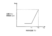
- FIG. 5 is a diagram for explaining the relationship between the coolant temperature Tw and the target fan rotational speed Nw.
- the target fan rotational speed Nw is adjusted according to the coolant temperature Tw.
- the target fan speed Nw is set to a constant value until the cooling water temperature Tw reaches T1, and the target fan speed Nw is increased linearly as the cooling water temperature Tw increases from T1 to T2. It is shown.
- the controller 20 calculates a target fan rotational speed Nw corresponding to the detection signal detected by the cooling water temperature sensor 21. As will be described later, the fan control unit 50 of the controller 20 executes this process. The same applies to the following fan control.
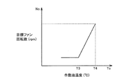
- FIG. 6 is a diagram illustrating the relationship between the hydraulic oil temperature To and the target fan rotational speed No.
- the target fan rotational speed No is adjusted according to the hydraulic oil temperature To.
- the target fan speed No is set to a constant value until the hydraulic oil temperature To reaches T3, and the target fan speed No is increased linearly as the hydraulic oil temperature To rises from T3 to T4. Has been.
- the controller 20 calculates a target fan rotational speed No corresponding to the detection signal detected by the hydraulic oil temperature sensor 22.
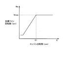
- FIG. 7 is a diagram for explaining the relationship between the engine speed E and the target fan speed Ne.
- the target fan speed Ne is adjusted according to the engine speed E.
- the target fan speed Ne is controlled to a constant value, and the target fan speed Ne is increased as the engine speed E increases. Yes.
- the case where the target fan rotational speed is maintained at the maximum rotational speed (Nmax) when the engine rotational speed E becomes equal to or higher than the predetermined rotational speed E1 is shown.
- the controller 20 calculates a target fan rotation speed Ne corresponding to the detection signal detected by the engine rotation sensor 23.
- the controller 20 calculates a command current value I1 for commanding the rotational speed of the fan 13 based on the calculated target fan rotational speed Nw, No, Ne. Specifically, the controller 20 calculates a command current value I1 to be commanded according to the rotation speed having the largest value among the calculated target fan rotation speeds Nw, No, Ne. Then, the calculated command current value I1 is output to the electromagnetic proportional valve 14c. Thereby, according to the detection result of each sensor, the ventilation volume with respect to the cooling core 10 from the fan 13 is adjusted. By adjusting the amount of air blown from the fan 13 to the cooling core 10, the cooling core 10 can be efficiently cooled.
- the method of adjusting the rotation speed of the fan 13 to the rotation speed having the largest value among the target fan rotation speeds Nw, No, Ne has been described as an example.
- the command current value I1 to be commanded may be calculated according to the rotation speed obtained by averaging the target fan rotation speeds Nw, No, Ne.
- the target fan speed may be selected according to a predetermined condition.
- a person skilled in the art can appropriately change the design to an appropriate method based on information on the characteristics of the bulldozer 1.
- control data for calculating the target fan speed as shown in FIGS. 5-7 and the like is stored in advance in the storage unit 20a.
- FIG. 8 is a diagram showing an example of a standard screen on which information related to the engine state is displayed on the display 115 of the operation panel 100.
- An icon is a symbol that displays things in a simple pattern.
- various data represented by numerical values are displayed on the display 115 together with a plurality of icons.
- the upper side or the upper side of the display 115 is a ceiling side of the cab 6 and is a side indicated by an arrow U, and the lower or lower side is a floor side of the cab 6 and a side indicated by an arrow B.
- a plurality (six in this example) of function switches 16a, 16b, 16c, 16d, 16e, and 16f are arranged.
- reference numeral 16 When these are not particularly distinguished, reference numeral 16 is used, and when they are distinguished, reference numerals 16a and 16b are used.
- Function guides 30a, 30b, 30c, 30d, and 30f as guide indices are displayed at positions corresponding to the respective function switches 16a, 16b, 16c, 16d, 16e, and 16f at the lower end of the screen of the display 115. ing.
- symbol 30 is used, and when distinguishing, the codes
- the plurality of function switches 16 are disposed below the display 115, but the plurality of function switches 16 may be disposed at other locations.
- the plurality of function switches 16 may be disposed on the side or above the display 115.
- a plurality of function guides 30 are displayed on the screen of the display 115 corresponding to the positions corresponding to the function switches 16.
- a plurality of function guides 30 are displayed corresponding to each function switch 16 at a side end portion in the screen of the display 115.
- Each function guide 30 is an index for guiding the function of the function switch 16, and is displayed on the display 115 in the form of an icon in this embodiment. That is, each function guide 30 displays the function of the corresponding function switch 16 in the form of an icon. Each function guide 30 is assigned a function to the screen on which these are displayed.
- the function guide 30 allows the operator to intuitively grasp the function of the function switch 16 and select the desired function switch 16. Further, the function guide 30 displays the function of the function switch 16, so that the visibility of the operator is improved.
- the display 115 displays five meter-type gauge icons. These are a multi-gauge 31, an engine water temperature gauge 32, a hydraulic oil temperature gauge 33, a fuel gauge 34, and a mission oil temperature gauge 35. These icons have a pointer and a memory on an arc, and display various gauge sizes by rotating the pointer.
- the display 115 includes an energy saving gauge 36 that indicates an index of energy saving operation based on the fuel consumption, a clock 37 that displays time, a status indicator 38 that indicates the current running state of the bulldozer 1, and the like.
- Function display icons 39a and 39b for displaying the function of the bulldozer 1 are displayed.
- the multi-gauge 31 is an indicator for switching and displaying information on a plurality of types of engine states with the function switch 16.
- the multigauge 31 can change information on the engine state displayed by the multigauge 31 by operating the function switch 16b.
- the example shown in FIG. 8 displays the rotational speed (the number of revolutions per unit time) of the engine 4 mounted on the bulldozer 1.
- the display of the multigauge 31 may be switched so as to display the traction force.
- Examples of other information displayed by the multigauge 31 include hydraulic oil pressure, engine oil pressure, battery voltage, traction force, vehicle speed, clock, and engine rotation speed. In the present embodiment, it is possible to switch the information displayed on the multigauge 31 one by one each time the function switch 16b is operated once.
- FIG. 9 is a diagram illustrating functional blocks of a control system including the controller 20 of the bulldozer 1.
- FIG. 9 the relationship between the controller 20 and other peripheral devices is shown.
- an operation panel 100 a lock lever 29, an engine 4, a governor motor 40, an engine controller 42, a fuel dial 44, a potentiometer 45, and a starter switch 46 are shown as peripheral devices.
- the governor motor 40 adjusts the fuel injection amount by the fuel injection device in the engine 4.
- the engine controller 42 controls the operation of the engine 4.
- the engine 4 is a diesel engine as an example.
- the engine speed of the engine 4 is set by the fuel dial 44 or the like.
- the fuel dial 44 is provided with a potentiometer 45.
- the amount of operation of the fuel dial 44 is detected by the potentiometer 45, and a dial command value (also referred to as a dial command value) relating to the rotational speed of the engine 4 is output to the engine controller 42.
- the target rotational speed of the engine 4 is adjusted according to the dial command value of the fuel dial 44.
- the engine controller 42 instructs the governor motor 40 on the basis of a dial command value relating to the rotational speed of the engine 4 according to the operation amount from the potentiometer 45 in accordance with an instruction from the controller 20, and controls the amount of fuel injected by the fuel injection device.
- the rotational speed of the engine 4 is adjusted.
- the starter switch 46 is connected to the engine controller 42. When the operator operates the starter switch 46 (set to start), a start signal is output to the engine controller 42 and the engine 4 is started.
- the dial command value from the fuel dial 44 and the start signal from the starter switch 46 may be input to the controller 20 via the engine controller 42.
- the controller 20 includes an idling stop control unit 51, a fan control unit 50, and an operation state detection unit 60.
- the idling stop control unit 51 controls an idling stop operation.
- the fan control unit 50 controls the rotation of the fan 13.
- the operation state detection unit 60 detects operation states of various operation levers.
- the idling stop control unit 51 includes an idling stop time setting unit 52, an idling stop timer 56, and an idling stop execution unit 57.
- the idling stop time setting unit 52 sets an idling stop time, which is an execution condition of the idling stop execution unit 57, according to an operation instruction using the function switch 16 of the operation panel 100.
- the idling stop execution unit 57 outputs an engine stop signal to the engine controller 42 so as to execute an idling stop operation for stopping the engine 4 when a predetermined condition is satisfied.
- the “idling stop operation” means an operation of stopping the engine 4 in an idling state of the work vehicle, that is, a state in which the work vehicle is on standby while the engine 4 is operating.
- This predetermined condition is an execution condition for executing the “idling stop operation”, and mainly means a condition relating to a predetermined time during which the idling state of the work vehicle continues.
- the “predetermined time” is also referred to as an idling stop time.
- the idling stop timer 56 is a timer that counts (clocks) time in accordance with an instruction from the operation state detection unit 60. Then, the count result is output to the idling stop execution unit 57.
- the idling stop execution unit 57 determines whether or not the idling stop time has elapsed based on the count result (timer value) counted by the idling stop timer 56. Output to the controller 42.
- the engine controller 42 receives the engine stop signal from the idling stop execution unit 57 and instructs the governor motor 40 to stop the engine 4.
- the fan control unit 50 calculates the target fan rotational speed based on the input of detection signals of various sensors as described above with reference to FIGS. 5 to 7, and outputs a command current value I1 corresponding thereto. In addition, the fan control unit 50 outputs a switching signal I2 that switches between forward and reverse rotation of the fan 13 in accordance with an instruction from the operation panel 100. The fan control unit 50 outputs a signal to the idling stop control unit 51 as necessary.
- the operation state detection unit 60 detects operation states of various operation levers.
- the operation state of the lock lever 29 is detected.
- the operations of the various operation levers are locked. Thereby, in a state where the movement of the work implement or the like is locked by the lock lever 29, even if the operator operates the blade operation lever 25 or the travel operation lever 28 or the like, the work implement or the like does not operate.
- the operation state detection unit 60 detects the operation when the lock lever 29 is operated to the lock side, and instructs the idling stop timer 56. Thereby, control of the idling stop operation is started.
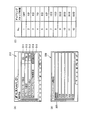
- FIG. 10 is a diagram for explaining the setting of the idling stop time.
- FIG. 10A shows an example of a user mode screen.
- the user mode screen is displayed by selecting the function switch 16 corresponding to the predetermined function guide 30 displayed on the display 115 on the standard screen described above.
- a user mode screen is displayed.
- the vehicle body setting screen 310 which can perform the setting regarding a vehicle body is displayed among the user mode screens.
- the operator operates the cursor 315 by selecting an instruction switch provided at a lower position on the screen, and the detailed setting related to the item corresponding to the position of the cursor 315 can be performed by selecting.
- an idling stop time setting screen 320 is shown.
- the idling stop time setting screen 320 is displayed when the cursor 315 is moved to the item “idling stop time setting” 314 displayed on the display 115 and the function switch for instructing the selection is pressed.
- idling stop time setting screen 320 a plurality of idling stop times can be set.
- a case where “OFF”, “5 minutes” to “9 minutes” can be set as an example of a setting range that can be selectively set is shown. It is possible to set a time longer than “9 minutes” by further moving the cursor 325 downward.
- the operator can set the desired idling stop time by operating the cursor 325 and selecting it. That is, information related to the set idling stop time is input from the operation panel 100 to the idling stop time setting unit 52 and set in the idling stop time setting unit 52.
- FIG. 10C here, a setting table for setting the idling stop time is shown.
- a setting table capable of setting 12 patterns is shown, and the case where “60 minutes” can be set as the longest idling stop time is shown.
- the idling stop time is selected and set from a plurality of items as the interface for setting the idling stop time in this example
- the maximum length of the idling stop time An interface may be provided in which a time bar that defines the time bar and a cursor that can be moved to an arbitrary position related to the time bar are displayed, and the idling stop time is set according to the position of the cursor with respect to the time bar.
- the idling stop time may be set by setting an arbitrary time by the operator inputting a numerical value.
- a cleaning function (cleaning mode) for cleaning the cooling core 10 is provided together with an idling stop function.
- the cleaning mode is a function for cleaning the cooling core when dirt or dust generated during the work rises and enters the cooling core or the like.
- the fan 13 is rotated reversely by driving the engine 4 in accordance with an instruction from the operator. Thereby, the blowing direction with respect to the cooling core 10 is reversed with respect to the direction at the time of forward rotation, and the foreign matter clogged in the cooling fin which comprises a cooling core is removed.
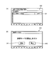
- FIG. 11 is a diagram for explaining the setting of the cleaning mode.
- FIG. 11A shows an example of setting the cleaning mode.
- the user mode screen is displayed by selecting the function switch 16 corresponding to the function guide 30 displayed on the display 115 on the standard screen described above. As an example, when the function switch 16f is operated, a user mode screen is displayed.
- the other setting screen 330 which can set about the cleaning mode among the user mode screens is displayed.
- the other setting screen 330 is provided with “ON” and “OFF” icons 331 indicating whether or not the cleaning mode has been started.
- icons 341 and 342 for selectively accepting “start” and “stop” of the cleaning mode are displayed together with a guidance display of “Do you want to start the cleaning mode”? Provided.
- the cleaning mode is set to “ON” by selecting the icon 341 with the cursor. Thereby, the cleaning mode is started. Specifically, an instruction to start the cleaning mode is input to the fan control unit 50 in accordance with an instruction from the operation panel 100.
- the fan control unit 50 outputs a switching signal I2 to the electromagnetic switching valve 15 in accordance with an instruction from the operation panel 100. Thereby, the electromagnetic switching valve 15 is switched to the B position in accordance with the switching signal I2, and the fan 13 rotates in the reverse direction.
- the fan control unit 50 outputs a command current value I1 for commanding the rotation speed of the fan 13 to the electromagnetic proportional valve 14c in accordance with an instruction from the operation panel 100.
- the command current value I1 is output so that the rotation speed of the fan becomes the maximum rotation.
- the fan control unit 50 notifies the idling stop execution unit 57 that the cleaning mode has been started. It is possible to prohibit the idling stop operation during the cleaning mode in accordance with the notification, as will be described later.
- the fan is rotated in the reverse rotation direction to blow off dust attached to the cooling core 10 such as a radiator or an oil cooler. That is, it is possible to remove the dust and the like that are clogged and to perform the cleaning process by blowing the fan 13 in the opposite direction to the cooling core.
- the cooling core 10 such as a radiator or an oil cooler.
- the operator can instruct the fan control unit 50 to stop the cleaning mode via the operation panel 100.
- the idling stop execution unit 57 stops the operation of the idling stop timer 56 when the cleaning mode is started. That is, the idling stop timer 56 stops counting the time during which the idling state continues. The idling stop execution unit 57 does not output the engine stop signal to the engine controller 42 because the idling stop timer 56 count value is stopped and the idling stop time does not elapse.
- the cleaning mode is set to “OFF” by selecting the function switch 16 and executing “stop” of the cleaning mode. Thereby, the cleaning mode ends.
- the fan control unit 50 outputs a switching signal I2 to the electromagnetic switching valve 15 in accordance with an instruction from the operation panel 100. Thereby, the electromagnetic switching valve 15 is switched to the A position in accordance with the switching signal I2, the reverse rotation of the fan 13 is stopped, and the fan 13 is rotated forward.
- the fan control unit 50 notifies the idling stop execution unit 57 that the cleaning mode has ended according to the cleaning mode stop instruction from the operation panel 100.
- the idling stop execution unit 57 resumes timing by the idling stop timer 56 according to the notification.
- the idling stop execution unit 57 stops the engine 4 when the idling stop time has reached the idling stop time according to the count value of the idling stop timer 56 and a predetermined condition for executing the idling stop operation is satisfied. Perform the action. That is, the idling stop execution unit 57 outputs an engine stop signal to the engine controller 42.
- the cleaning mode will be described in the case where the cleaning mode is terminated by selecting the function switch 16 and executing the “stop” of the cleaning mode after the cleaning mode is started.
- the predetermined time those skilled in the art can appropriately set an appropriate time, and the predetermined time may be changed according to the cleaning status of the cooling core 10. For example, the predetermined time may be changed based on the detection result of a sensor that detects dirt. Or you may make it continue cleaning mode until it becomes below a predetermined detection level based on the detection result of the said sensor.
- FIG. 12 is a flowchart of the idling stop control process of the idling stop control unit 51.
- the idling stop control unit 51 determines whether or not the lock lever 29 is locked (ON) (step S1). Specifically, the operation state detection unit 60 detects that the lock lever 29 is locked, and outputs it to the idling stop timer 56. The idling stop timer 56 determines that the lock lever 29 is locked (ON) based on the detection signal input from the operation state detection unit 60.
- step S1 determines that the lock lever 29 is locked (ON) in step S1 (YES in step S1), is the temperature of the cooling water or the hydraulic oil within a predetermined range? It is determined whether or not (step S2). Specifically, the idling stop execution unit 57 determines whether or not the temperature of the cooling water or hydraulic oil is within a predetermined range based on the input of detection signals from various sensors.
- step S2 When the idling stop control unit 51 determines in step S2 that the temperature of the cooling water or hydraulic oil is not within the predetermined range (NO in step S2), the idling stop timer is not started (started), and the process proceeds to step S1. Return. That is, the idling stop operation is not executed when the temperature of the cooling water or the hydraulic oil is not within the predetermined range.
- the temperature of the cooling water or hydraulic oil is not within the specified range, specifically, in cold districts, it is necessary to increase the temperature of the cooling water or hydraulic oil by warm-up operation. It is possible to achieve a stable state where smooth operation of the work vehicle is possible without performing the operation.
- the temperature of the cooling water or hydraulic oil when the temperature of the cooling water or hydraulic oil is high, the temperature of the cooling water or hydraulic oil is lowered by rotating the fan 13 or the like, and the work vehicle is stopped in a temperature state within a predetermined range. It is possible to protect the internal device of the vehicle. It should be noted that within the predetermined range, those skilled in the art can appropriately change the design to an appropriate range based on information regarding the characteristics of the bulldozer 1. Further, the predetermined range of the cooling water temperature and the predetermined range of the temperature of the hydraulic oil need not be the same range, and can be changed according to the respective characteristics. In this example, a case where it is determined whether or not the temperature of the cooling water or the hydraulic oil is within a predetermined range will be described, but either one may be determined, or both may be determined. .
- step S2 the idling stop control unit 51 starts (starts) the idling stop timer 56 (timer on) when it is determined that the temperature of the cooling water or hydraulic oil is within the predetermined range (YES in step S2). (Step S3). Specifically, the idling stop execution unit 57 instructs the idling stop timer 56 to count the time according to the input of the detection signal from the operation state detection unit 60. Then, the idling stop timer 56 outputs the counted timer value to the idling stop execution unit 57.
- the idling stop control unit 51 determines whether or not the lock lever 29 is turned off (step S4). Specifically, the operation state detection unit 60 detects that the lock lever 29 has been released (OFF), and outputs it to the idling stop timer 56. Then, the idling stop timer 56 determines that the lock lever 29 has been released based on the input of the detection signal from the operation state detection unit 60.
- step S4 when it is determined that the lock lever 29 has been released (YES in step S4), the idling stop control unit 51 resets the idling stop timer 56 (step S11). Specifically, the idling stop timer 56 stops counting the time based on the input of the detection signal and resets the counter value.
- step S1 the process returns to step S1, and the idling stop control unit 51 waits again until the lock lever 29 is locked (ON).
- step S4 determines in step S4 that the lock lever 29 is not released (NO in step S4), the process proceeds to the next step S5.
- the idling stop control unit 51 determines whether or not the fan is rotating forward (step S5). Specifically, the idling stop execution unit 57 determines whether or not a notification indicating that the cleaning mode has been started has been received from the fan control unit 50. The idling stop execution unit 57 determines that the fan is rotating forward when there is no notification from the fan control unit 50 that the cleaning mode has started, and the cleaning mode from the fan control unit 50 is started. If there is a notification to that effect, it is determined that the fan is rotating in the reverse direction.
- step S5 when it is determined that the fan is rotating forward (YES in step S5), the idling stop control unit 51 determines whether or not a predetermined time has elapsed (step S6). Specifically, the idling stop execution unit 57 sets the timer value to the idling stop based on the idling stop time that is the predetermined time set by the idling stop time setting unit 52 and the timer value input from the idling stop timer 56. Determine whether the time has been exceeded. Then, the idling stop execution unit 57 determines that the predetermined time has elapsed when the timer value exceeds the idling stop time.
- step S6 when it is determined that the predetermined time has elapsed (YES in step S6), the idling stop control unit 51 outputs an engine stop instruction (step S7). Specifically, the idling stop execution unit 57 outputs an engine stop signal to the engine controller 42. As a result, the engine controller 42 instructs the governor motor 40 to stop the engine 4.
- the idling stop control part 51 finishes a process (end).
- the idling state of the bulldozer 1 has continued for a predetermined time, it is possible to automatically stop the engine 4 of the bulldozer 1 to suppress energy consumption and noise.
- step S6 when it is determined in step S6 that the predetermined time has not elapsed (NO in step S6), the idling stop control unit 51 returns to step S4 and repeats the above processing until the predetermined time has elapsed.
- step S5 determines in step S5 that the fan is not rotating forward (NO in step S5)
- the idling stop timer 56 is stopped (stopped) (timer off) (step S8).
- the idling stop execution unit 57 determines that the fan is not rotating forward, that is, the fan is rotating backward, in other words, the cleaning mode from the fan control unit 50 is started.
- the idling stop timer 56 is instructed to stop the time counting in the idling stop timer 56.
- the idling stop control unit 51 determines whether or not the fan is rotating forward (step S9). Specifically, when it is determined that the fan is rotating forward, the idling stop execution unit 57 determines whether or not a notification indicating that the cleaning mode has ended is received from the fan control unit 50 in other words. When the idling stop execution unit 57 receives a notification from the fan control unit 50 that the cleaning mode has ended after the cleaning mode is started, the fan stops rotating in the reverse direction and is rotating forward. to decide. On the other hand, when there is no notification from the fan control unit 50 that the cleaning mode has been completed, the idling stop execution unit 57 determines that the fan has not stopped reverse rotation, that is, is rotating backward.
- step S9 when it is determined that the fan is not rotating forward (NO in step S9), the idling stop control unit 51 maintains the state.
- step S9 when the idling stop control unit 51 determines in step S9 that the fan is rotating forward (YES in step S9), the idling stop timer 56 is restarted (timer on) (step S10). Specifically, the idling stop execution unit 57 instructs the idling stop timer 56 to restart counting the time according to the input of the detection signal from the operation state detection unit 60. Then, the idling stop timer 56 outputs the counted timer value to the idling stop execution unit 57.
- step S4 the idling stop control part 51 returns to step S4, and repeats the said process until predetermined time passes.
- the idling stop timer 56 starts counting (timekeeping) in this process, when the cleaning mode is started, the idling stop timer 56 counts until the cleaning mode ends. Is stopped.
- the engine 4 of the bulldozer 1 is not stopped by the idling stop operation. That is, when the cleaning mode in which the fan rotates in reverse is being executed, control is performed so that the idling stop operation is not executed until the cleaning mode is completed. Thereby, when the cleaning mode is started, the engine 4 is not stopped by the idling stop operation, so that the cleaning mode can be continued. That is, the reverse rotation of the fan 13 is continued until the cleaning operation is completed. Therefore, it is possible to effectively perform the cleaning operation on the cooling core 10.
- the counting of the idling stop timer 56 is resumed, and when the idling state has elapsed for a predetermined time, the engine 4 of the bulldozer 1 is stopped by the idling stop operation. .
- the idling stop timer 56 is restarted to control the idling state so that it does not become unnecessarily long, and energy consumption and noise can be suppressed. is there.
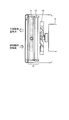
- FIG. 13 is a view for explaining the form of the side cover provided in the bulldozer 1.
- the cover body 5 is provided with a side cover 5a.
- the side cover 5 a, the cooling core 10, the fan 13, and the engine 4 are provided corresponding to at least one side portion.
- the one side cover 5a is provided in the one side of the bulldozer 1 is shown, you may make it provide the side cover 5a in both sides.
- the side cover 5a is a gull wing type in this example, and can open the inside of the cover body that can be opened and closed.
- the side cover 5a provided not only in a gull wing type but so that opening and closing is possible, what kind of format is also employable.
- the side cover 5a can be opened when the fan 13 is rotating in the reverse direction.
- the cooling core can be efficiently cleaned by executing the cleaning mode in this state.
- the configuration is not limited to manual operation.
- the side cover 5a is automatically set in the cleaning mode. It is also possible to control so that 5a shifts to the open state, and it is possible to avoid the trouble of the operator.
- a bulldozer has been described as an example of a work vehicle.
- the present invention can also be applied to a work vehicle such as a hydraulic excavator or a wheel loader, and is a working machine provided with an engine 4. It can be applied to anything.
- the idling state count (timekeeping) for control is interrupted, and the engine 4 automatically stops during the reverse rotation of the fan 13. It is preventing. That is, in the above description, the method for determining whether or not the fan 13 is rotating in reverse until the idling state continues for a predetermined time has been described. As another example, when the idling state continues for a predetermined time when the idling stop control is executed, it is determined whether or not the fan 13 is rotating in the reverse direction. If the fan 13 is in the reverse rotation state, the idling stop control is performed. The unit 51 may not output the engine stop signal to the engine controller 42.
- the idling state count (time keeping) in the idling stop timer 56 is not started, and the engine 4 is automatically stopped during the reverse rotation of the fan 13. It may be possible to avoid this.
Landscapes
- Engineering & Computer Science (AREA)
- General Engineering & Computer Science (AREA)
- Mining & Mineral Resources (AREA)
- Civil Engineering (AREA)
- Structural Engineering (AREA)
- Mechanical Engineering (AREA)
- Combustion & Propulsion (AREA)
- Chemical & Material Sciences (AREA)
- Physics & Mathematics (AREA)
- Fluid Mechanics (AREA)
- Component Parts Of Construction Machinery (AREA)
- Operation Control Of Excavators (AREA)
- Cooling, Air Intake And Gas Exhaust, And Fuel Tank Arrangements In Propulsion Units (AREA)
- Output Control And Ontrol Of Special Type Engine (AREA)
- Control Of Vehicle Engines Or Engines For Specific Uses (AREA)
Abstract
Description
図1は、ブルドーザ1の側面図である。
走行体2は、車体3の下部に走行自在に設けられ、一対の無端状の履帯を回転させることにより不整地における走行が可能となっている。
エンジン4は、車体3の前部に設けられたエンジンルームに設けられる。エンジン4は一例としてディーゼルエンジンである。
ブレード7は、車体3の前方の作業機として装着され、地面を削り取って土砂を押し運ぶための作業機であって、後述するブレード操作レバーの操作に応じて油圧シリンダ7aによって駆動される。
図2は、運転室6の内部構成を示す斜視図である。
次に、ブルドーザ1の油圧駆動システムについて説明する。
図3に示すように、ブルドーザ1の駆動システムは、ブレード7と、エンジン4と、水ポンプ4aと、ウォータジャケット4cと、ラジエータ11と、油圧ポンプ14,43と、電磁切換弁15と、油圧モータ41と、ファン13と、オイルクーラ12と、管路4b,11a,12a,14a,15a,31a,32a,35aと、チェック弁18と、作動油タンク17と、作動油温度センサ22と、コントローラ20と、サーボ弁14b,31bと、電磁比例弁14cと、減圧弁48と、コントロールバルブ47と、油圧シリンダ7aと、パイロット圧操作弁49と、ブレード操作レバー25と、ロードセンシング弁31cと、冷却水温度センサ21と、エンジン回転センサ23と、操作パネル100とを含む。
油圧ポンプ14から吐出された作動油は、管路14aを経由して電磁切換弁15の入力ポートに流入し、電磁切換弁15により固定容量型の油圧モータ41に供給される。
図4は、ファン近傍の冷却コア10の配置について説明する図である。
本例においては、ファン13を正回転する場合の制御について説明する。
図5に示されるように、冷却水温度Twに従って目標ファン回転数Nwを調整する。本例においては、冷却水温度TwがT1となるまで一定の目標ファン回転数Nwに設定され、そして、冷却水温度TwがT1からT2に上昇するに従って線形に目標ファン回転数Nwを上昇させる場合が示されている。
図6に示されるように、作動油温度Toに従って目標ファン回転数Noを調整する。本例においては、作動油温度ToがT3となるまで一定の目標ファン回転数Noに設定され、作動油温度ToがT3からT4に上昇するに従って線形に目標ファン回転数Noを上昇させる場合が示されている。
図7に示されるように、エンジン回転数Eに従って目標ファン回転数Neを調整する。本例においては、エンジン回転数Eが低い場合には目標ファン回転数Neは一定の値に制御され、そして、エンジン回転数Eが上昇するに従って目標ファン回転数Neを上昇させる場合が示されている。なお、本例においては、エンジン回転数Eが所定の回転数E1以上となった場合には目標ファン回転数を最大回転数(Nmax)に維持する場合が示されている。
次に、操作パネル100の構成を説明する。
図9は、ブルドーザ1のコントローラ20を含む制御システムの機能ブロックを説明する図である。
エンジンコントローラ42は、エンジン4の動作を制御する。エンジン4は、一例としてディーゼルエンジンである。エンジン4のエンジン回転数は、燃料ダイヤル44等によって設定される。
ファン制御部50は、ファン13の回転を制御する。
アイドリングストップ制御部51は、アイドリングストップ時間設定部52と、アイドリングストップタイマ56と、アイドリングストップ実行部57とを含む。
アイドリングストップタイマ56は、操作状態検出部60からの指示に従って時間をカウント(計時)するタイマである。そして、カウント結果をアイドリングストップ実行部57に出力する。アイドリングストップ実行部57は、アイドリングストップタイマ56でカウントされたカウント結果(タイマ値)に基づいて、アイドリングストップ時間が経過したか否かを判断し、経過したと判断した場合にエンジン停止信号をエンジンコントローラ42に出力する。エンジンコントローラ42は、アイドリングストップ実行部57からのエンジン停止信号を受けて、ガバナモータ40に指示してエンジン4を停止させる。
図10は、アイドリングストップ時間の設定について説明するための図である。
当該ユーザモード画面は、上記で説明した標準画面において、ディスプレイ115に表示される所定のファンクションガイド30に対応するファンクションスイッチ16を選択することにより表示される。一例として、ファンクションスイッチ16fを操作した場合に、ユーザモード画面が表示される。
本例における作業車両の機能としては、アイドリングストップ機能とともに、冷却コア10を清掃するための清掃機能(清掃モード)が設けられている。清掃モードとは、作業時に発生する土砂や塵埃が舞い上がって冷却コア等に侵入する場合に、当該冷却コアを清掃する機能である。具体的には、エンジン4を停止した状態で保守点検等を行うメンテナンス処理とは異なり、操作者からの指示に従ってエンジン4の駆動によりファン13を逆回転させる。これにより、冷却コア10に対する送風方向を正回転の際の方向に対して反転させて、冷却コアを構成する冷却フィンに目詰まりしている異物を除去する。
図11(A)では、清掃モードの設定の一例が示されている。
図12は、アイドリングストップ制御部51のアイドリングストップ制御処理のフローチャートである。
当該処理により、ブルドーザ1のアイドリング状態が所定時間継続している場合に、自動的にブルドーザ1のエンジン4を停止させて、エネルギーの消費および騒音を抑えることが可能である。
図13は、ブルドーザ1に設けられたサイドカバーの形態を説明する図である。
当該サイドカバー5a、冷却コア10、ファン13、エンジン4の少なくともいずれか1つの側部に対応して設けられる。なお、本例においては、1つのサイドカバー5aがブルドーザ1の片側に設けられている場合について示されているが、両側にサイドカバー5aが設けられるようにしても良い。
Claims (7)
- エンジンと、
作業車両に搭載された冷却コアと、
前記冷却コアに対して送風する正逆回転が可能なファンと、
前記エンジンの駆動により前記ファンを駆動する油圧駆動部と、
前記油圧駆動部による前記ファンの回転状態およびアイドリング状態に基づいて、前記エンジンを停止させるアイドリングストップ実行部とを備え、
前記アイドリングストップ実行部は、
前記ファンの回転が正回転であり、前記アイドリング状態が所定時間継続した場合に、前記エンジンを停止させ、
前記ファンの回転が逆回転の場合には、前記エンジンを停止させない、作業車両。 - 運転室と、
前記運転室内に設けられ、操作者による前記ファンの逆回転の指示を受け付ける操作パネルをさらに備え、
前記油圧駆動部は、前記操作パネルに対する前記ファンの逆回転の指示を受け付けた場合に前記ファンを逆回転駆動する、請求項1記載の作業車両。 - 前記油圧駆動部は、
前記ファンを駆動する油圧モータと、
前記エンジンの駆動により作動油を前記油圧モータへ供給する油圧ポンプと、
前記油圧モータへ前記作動油が流れる経路を切り替える切替弁と、
前記油圧ポンプから前記油圧モータへの作動油の供給量を調整する調整部とをさらに含む、請求項1または2に記載の作業車両。 - 前記ファンの正逆回転の回転数は、前記油圧ポンプから前記油圧モータへの前記作動油の供給量に従って可変可能に設けられ、
前記調整部は、前記ファンが逆回転の場合に前記ファンの回転数が最大回転数となるように前記油圧ポンプから前記油圧モータへの前記作動油の供給量を調整する、請求項3に記載の作業車両。 - 前記作業車両の操作状態を検出する検出部をさらに備え、
前記アイドリングストップ実行部は、
前記検出部が前記作業車両の操作状態が無操作状態であることを検出し、かつ、前記ファンの回転が正回転であり、前記アイドリング状態が所定時間継続した場合に、前記エンジンを停止させ、
前記ファンの回転が逆回転の場合には、前記エンジンを停止させない、請求項1~4のいずれか一項に記載の作業車両。 - 前記エンジンの冷却水あるいは作動油の温度を検出するセンサをさらに備え、
前記アイドリングストップ実行部は、
前記センサで検出された前記エンジンの冷却水あるいは作動油の温度が所定範囲内であり、かつ、前記ファンの回転が正回転であり、前記アイドリング状態が所定時間継続した場合に、前記エンジンを停止させ、
前記ファンの回転が逆回転の場合には、前記エンジンを停止させない、請求項1~4のいずれか一項に記載の作業車両。 - 前記エンジンと、前記冷却コアと、前記ファンとを覆うように設けられるカバー体をさらに備え、
前記カバー体は、前記エンジンと、前記冷却コアと、前記ファンの少なくとも1つの側部に対して、前記ファンが逆回転の場合に開状態とすることが可能なサイドカバーを含む、請求項1~6のいずれか一項に記載の作業車両。
Priority Applications (4)
| Application Number | Priority Date | Filing Date | Title |
|---|---|---|---|
| PCT/JP2013/075360 WO2014192172A1 (ja) | 2013-09-19 | 2013-09-19 | 作業車両 |
| CN201380003195.9A CN104024610B (zh) | 2013-09-19 | 2013-09-19 | 作业车辆 |
| JP2013546507A JP5450907B1 (ja) | 2013-09-19 | 2013-09-19 | 作業車両 |
| US14/345,993 US9580889B2 (en) | 2013-09-19 | 2013-09-19 | Work vehicle |
Applications Claiming Priority (1)
| Application Number | Priority Date | Filing Date | Title |
|---|---|---|---|
| PCT/JP2013/075360 WO2014192172A1 (ja) | 2013-09-19 | 2013-09-19 | 作業車両 |
Publications (1)
| Publication Number | Publication Date |
|---|---|
| WO2014192172A1 true WO2014192172A1 (ja) | 2014-12-04 |
Family
ID=50614499
Family Applications (1)
| Application Number | Title | Priority Date | Filing Date |
|---|---|---|---|
| PCT/JP2013/075360 Ceased WO2014192172A1 (ja) | 2013-09-19 | 2013-09-19 | 作業車両 |
Country Status (4)
| Country | Link |
|---|---|
| US (1) | US9580889B2 (ja) |
| JP (1) | JP5450907B1 (ja) |
| CN (1) | CN104024610B (ja) |
| WO (1) | WO2014192172A1 (ja) |
Cited By (3)
| Publication number | Priority date | Publication date | Assignee | Title |
|---|---|---|---|---|
| JP2018035558A (ja) * | 2016-08-31 | 2018-03-08 | 株式会社小松製作所 | ホイールローダ及びアダプタ |
| WO2018109854A1 (ja) * | 2016-12-14 | 2018-06-21 | 芝海株式会社 | 作業車両、および作業車両の冷却装置 |
| EP4502349A1 (de) * | 2023-08-04 | 2025-02-05 | Kässbohrer Geländefahrzeug AG | Ziviles kettenfahrzeug |
Families Citing this family (23)
| Publication number | Priority date | Publication date | Assignee | Title |
|---|---|---|---|---|
| KR101691317B1 (ko) * | 2013-11-19 | 2017-01-09 | 가부시키가이샤 고마쓰 세이사쿠쇼 | 작업 차량의 표시 장치 및 그 표시 방법 |
| CN104527403B (zh) * | 2015-01-05 | 2017-05-17 | 吉林大学 | 一种大型油电混合动力道路清扫车动力驱动系统及其控制策略 |
| JP2016160649A (ja) * | 2015-03-02 | 2016-09-05 | 株式会社小松製作所 | 作業車両及びリッパ装置 |
| WO2018185846A1 (ja) * | 2017-04-04 | 2018-10-11 | 株式会社小松製作所 | 作業車両 |
| ITUB20160476A1 (it) * | 2016-01-19 | 2017-07-19 | Comacchio S R L | Sistema di raffreddamento migliorato per motori endotermici di macchine operatrici e/o movimento terra |
| CN106050816B (zh) * | 2016-06-30 | 2018-06-26 | 中联重科股份有限公司渭南分公司 | 液压散热控制方法、装置和系统 |
| CN106347105A (zh) * | 2016-09-14 | 2017-01-25 | 浙江鼎力机械股份有限公司 | 可反向排污的动力系统及车体、高空作业平台 |
| EP3425211B1 (en) * | 2016-09-28 | 2021-05-05 | Hitachi Construction Machinery Co., Ltd. | Work vehicle with confluence control device |
| US10151543B2 (en) | 2016-12-15 | 2018-12-11 | Caterpillar Inc. | Modular hydraulics |
| CN106985658B (zh) * | 2017-04-24 | 2023-09-29 | 中国人民解放军陆军装甲兵学院士官学校 | 一种基于电子风扇的混合动力专用发动机散热装置的控制方法 |
| JP6749877B2 (ja) * | 2017-09-26 | 2020-09-02 | 日立建機株式会社 | 冷却ファン制御装置 |
| KR102652751B1 (ko) * | 2018-02-09 | 2024-04-01 | 가부시끼 가이샤 구보다 | 콤바인 |
| JP2019190107A (ja) * | 2018-04-24 | 2019-10-31 | ヤンマー株式会社 | 電動式作業機械 |
| JP7051631B2 (ja) * | 2018-07-20 | 2022-04-11 | 株式会社クボタ | 作業機 |
| JP7257132B2 (ja) * | 2018-11-15 | 2023-04-13 | 株式会社小松製作所 | 作業機械 |
| JP7160646B2 (ja) | 2018-11-22 | 2022-10-25 | キャタピラー エス エー アール エル | 建設機械 |
| JP6815442B2 (ja) * | 2019-06-26 | 2021-01-20 | 日本国土開発株式会社 | スクレーパ車両及びその制御方法並びに牽引車両 |
| JP7337632B2 (ja) * | 2019-09-30 | 2023-09-04 | 株式会社小松製作所 | バルブシステム、作業機械、バルブの制御方法、プログラム、および記録媒体 |
| US11668228B2 (en) * | 2020-05-28 | 2023-06-06 | Deere & Company | Variable pitch fan control system |
| JP7481985B2 (ja) * | 2020-09-30 | 2024-05-13 | 株式会社小松製作所 | 作業機械 |
| JP7848102B2 (ja) * | 2022-01-26 | 2026-04-20 | ヤンマーホールディングス株式会社 | 作業車両 |
| CN115211285B (zh) * | 2022-07-01 | 2023-05-23 | 中国铁建重工集团股份有限公司 | 一种采棉机绞龙液压控制系统和液压控制方法 |
| EP4513012A4 (en) * | 2022-08-29 | 2026-02-18 | Hitachi Construction Mach Co | TRANSPORT VEHICLE |
Citations (3)
| Publication number | Priority date | Publication date | Assignee | Title |
|---|---|---|---|---|
| JP2003065097A (ja) * | 2001-08-27 | 2003-03-05 | Shin Caterpillar Mitsubishi Ltd | 作業機械のエンジン制御装置 |
| JP2004197682A (ja) * | 2002-12-19 | 2004-07-15 | Komatsu Ltd | 建設機械 |
| JP2006057600A (ja) * | 2004-08-24 | 2006-03-02 | Sumitomo (Shi) Construction Machinery Manufacturing Co Ltd | 建設機械の冷却装置 |
Family Cites Families (4)
| Publication number | Priority date | Publication date | Assignee | Title |
|---|---|---|---|---|
| US6076488A (en) * | 1997-03-17 | 2000-06-20 | Shin Caterpillar Mitsubishi Ltd. | Cooling device for a construction machine |
| KR101527218B1 (ko) * | 2008-12-18 | 2015-06-10 | 두산인프라코어 주식회사 | 건설기계의 냉각장치 |
| US8370051B2 (en) * | 2009-01-05 | 2013-02-05 | Ford Global Technologies, Llc | Methods and systems for assisted direct start control |
| JP2013079040A (ja) | 2011-10-05 | 2013-05-02 | Kubota Corp | 乗用型作業車 |
-
2013
- 2013-09-19 CN CN201380003195.9A patent/CN104024610B/zh active Active
- 2013-09-19 US US14/345,993 patent/US9580889B2/en active Active
- 2013-09-19 WO PCT/JP2013/075360 patent/WO2014192172A1/ja not_active Ceased
- 2013-09-19 JP JP2013546507A patent/JP5450907B1/ja active Active
Patent Citations (3)
| Publication number | Priority date | Publication date | Assignee | Title |
|---|---|---|---|---|
| JP2003065097A (ja) * | 2001-08-27 | 2003-03-05 | Shin Caterpillar Mitsubishi Ltd | 作業機械のエンジン制御装置 |
| JP2004197682A (ja) * | 2002-12-19 | 2004-07-15 | Komatsu Ltd | 建設機械 |
| JP2006057600A (ja) * | 2004-08-24 | 2006-03-02 | Sumitomo (Shi) Construction Machinery Manufacturing Co Ltd | 建設機械の冷却装置 |
Cited By (4)
| Publication number | Priority date | Publication date | Assignee | Title |
|---|---|---|---|---|
| JP2018035558A (ja) * | 2016-08-31 | 2018-03-08 | 株式会社小松製作所 | ホイールローダ及びアダプタ |
| WO2018109854A1 (ja) * | 2016-12-14 | 2018-06-21 | 芝海株式会社 | 作業車両、および作業車両の冷却装置 |
| JPWO2018109854A1 (ja) * | 2016-12-14 | 2018-12-13 | 芝海株式会社 | 作業車両、および作業車両の冷却装置 |
| EP4502349A1 (de) * | 2023-08-04 | 2025-02-05 | Kässbohrer Geländefahrzeug AG | Ziviles kettenfahrzeug |
Also Published As
| Publication number | Publication date |
|---|---|
| CN104024610B (zh) | 2016-03-09 |
| CN104024610A (zh) | 2014-09-03 |
| US20160251832A1 (en) | 2016-09-01 |
| US9580889B2 (en) | 2017-02-28 |
| JP5450907B1 (ja) | 2014-03-26 |
| JPWO2014192172A1 (ja) | 2017-02-23 |
Similar Documents
| Publication | Publication Date | Title |
|---|---|---|
| JP5450907B1 (ja) | 作業車両 | |
| JP4285866B2 (ja) | 油圧駆動冷却ファン | |
| KR101005001B1 (ko) | 유압식 구동 팬을 위한 제어 장치 | |
| KR101698287B1 (ko) | 작업 차량 | |
| KR101614673B1 (ko) | 작업 차량 | |
| US8966918B2 (en) | Construction machine and control method for cooling fan | |
| RU2658403C2 (ru) | Улучшенное прогревание гидравлической жидкости с использованием реверсирования вентилятора с гидроприводом | |
| EP3438356B1 (en) | Shovel | |
| JP2005232792A (ja) | 建設機械の冷却装置 | |
| JP7328937B2 (ja) | 建設機械 | |
| WO2014185520A1 (ja) | 作業車両および作業車両の制御方法 | |
| WO2019188415A1 (ja) | 作業車両 | |
| JP6982592B2 (ja) | 建設機械 | |
| JP5816601B2 (ja) | 作業機械の冷却装置 | |
| JP2021050474A (ja) | 作業機械 | |
| US20250003182A1 (en) | Work machine and control method for work machine | |
| JP2008126843A (ja) | 作業機械の冷却装置 | |
| JP7399844B2 (ja) | 作業機 | |
| JP5762509B2 (ja) | 作業車両 | |
| KR20170028002A (ko) | 작업기계 | |
| JP2005290890A (ja) | 作業用機械におけるオーバーヒート防止システム | |
| JP2011021615A (ja) | 冷却用油圧駆動ファンの制御装置および制御方法 |
Legal Events
| Date | Code | Title | Description |
|---|---|---|---|
| WWE | Wipo information: entry into national phase |
Ref document number: 201380003195.9 Country of ref document: CN |
|
| ENP | Entry into the national phase |
Ref document number: 2013546507 Country of ref document: JP Kind code of ref document: A |
|
| WWE | Wipo information: entry into national phase |
Ref document number: 14345993 Country of ref document: US |
|
| 121 | Ep: the epo has been informed by wipo that ep was designated in this application |
Ref document number: 13886073 Country of ref document: EP Kind code of ref document: A1 |
|
| NENP | Non-entry into the national phase |
Ref country code: DE |
|
| 122 | Ep: pct application non-entry in european phase |
Ref document number: 13886073 Country of ref document: EP Kind code of ref document: A1 |