WO2014192065A1 - 車両用アブソーバシステム - Google Patents
車両用アブソーバシステム Download PDFInfo
- Publication number
- WO2014192065A1 WO2014192065A1 PCT/JP2013/064652 JP2013064652W WO2014192065A1 WO 2014192065 A1 WO2014192065 A1 WO 2014192065A1 JP 2013064652 W JP2013064652 W JP 2013064652W WO 2014192065 A1 WO2014192065 A1 WO 2014192065A1
- Authority
- WO
- WIPO (PCT)
- Prior art keywords
- sprung
- absorber
- unsprung
- force
- vehicle
- Prior art date
Links
Images


Classifications
-
- B—PERFORMING OPERATIONS; TRANSPORTING
- B60—VEHICLES IN GENERAL
- B60G—VEHICLE SUSPENSION ARRANGEMENTS
- B60G17/00—Resilient suspensions having means for adjusting the spring or vibration-damper characteristics, for regulating the distance between a supporting surface and a sprung part of vehicle or for locking suspension during use to meet varying vehicular or surface conditions, e.g. due to speed or load
- B60G17/06—Characteristics of dampers, e.g. mechanical dampers
- B60G17/08—Characteristics of fluid dampers
-
- B—PERFORMING OPERATIONS; TRANSPORTING
- B60—VEHICLES IN GENERAL
- B60G—VEHICLE SUSPENSION ARRANGEMENTS
- B60G17/00—Resilient suspensions having means for adjusting the spring or vibration-damper characteristics, for regulating the distance between a supporting surface and a sprung part of vehicle or for locking suspension during use to meet varying vehicular or surface conditions, e.g. due to speed or load
- B60G17/015—Resilient suspensions having means for adjusting the spring or vibration-damper characteristics, for regulating the distance between a supporting surface and a sprung part of vehicle or for locking suspension during use to meet varying vehicular or surface conditions, e.g. due to speed or load the regulating means comprising electric or electronic elements
- B60G17/018—Resilient suspensions having means for adjusting the spring or vibration-damper characteristics, for regulating the distance between a supporting surface and a sprung part of vehicle or for locking suspension during use to meet varying vehicular or surface conditions, e.g. due to speed or load the regulating means comprising electric or electronic elements characterised by the use of a specific signal treatment or control method
-
- B—PERFORMING OPERATIONS; TRANSPORTING
- B60—VEHICLES IN GENERAL
- B60G—VEHICLE SUSPENSION ARRANGEMENTS
- B60G2400/00—Indexing codes relating to detected, measured or calculated conditions or factors
- B60G2400/10—Acceleration; Deceleration
-
- B—PERFORMING OPERATIONS; TRANSPORTING
- B60—VEHICLES IN GENERAL
- B60G—VEHICLE SUSPENSION ARRANGEMENTS
- B60G2400/00—Indexing codes relating to detected, measured or calculated conditions or factors
- B60G2400/10—Acceleration; Deceleration
- B60G2400/102—Acceleration; Deceleration vertical
-
- B—PERFORMING OPERATIONS; TRANSPORTING
- B60—VEHICLES IN GENERAL
- B60G—VEHICLE SUSPENSION ARRANGEMENTS
- B60G2400/00—Indexing codes relating to detected, measured or calculated conditions or factors
- B60G2400/10—Acceleration; Deceleration
- B60G2400/104—Acceleration; Deceleration lateral or transversal with regard to vehicle
-
- B—PERFORMING OPERATIONS; TRANSPORTING
- B60—VEHICLES IN GENERAL
- B60G—VEHICLE SUSPENSION ARRANGEMENTS
- B60G2400/00—Indexing codes relating to detected, measured or calculated conditions or factors
- B60G2400/10—Acceleration; Deceleration
- B60G2400/106—Acceleration; Deceleration longitudinal with regard to vehicle, e.g. braking
-
- B—PERFORMING OPERATIONS; TRANSPORTING
- B60—VEHICLES IN GENERAL
- B60G—VEHICLE SUSPENSION ARRANGEMENTS
- B60G2400/00—Indexing codes relating to detected, measured or calculated conditions or factors
- B60G2400/20—Speed
- B60G2400/202—Piston speed; Relative velocity between vehicle body and wheel
-
- B—PERFORMING OPERATIONS; TRANSPORTING
- B60—VEHICLES IN GENERAL
- B60G—VEHICLE SUSPENSION ARRANGEMENTS
- B60G2400/00—Indexing codes relating to detected, measured or calculated conditions or factors
- B60G2400/60—Load
- B60G2400/63—Location of the center of gravity
-
- B—PERFORMING OPERATIONS; TRANSPORTING
- B60—VEHICLES IN GENERAL
- B60G—VEHICLE SUSPENSION ARRANGEMENTS
- B60G2500/00—Indexing codes relating to the regulated action or device
- B60G2500/10—Damping action or damper
Definitions
- the present invention relates to a vehicle absorber system mounted on a vehicle with a hydraulic shock absorber as a main component.
- the relative motion speed between the sprung portion and the unsprung portion (hereinafter sometimes referred to as “sprung unsprung relative velocity”).
- sprung unsprung relative velocity the relative motion speed between the sprung portion and the unsprung portion
- the unsprung unsprung relative speed is detected using a load sensor, and the detected unsprung unsprung relative speed is used to detect the relative relationship between the unsprung and unsprung parts.
- the direction of the operation (hereinafter sometimes referred to as “the unsprung and unsprung relative operation direction”) is grasped, and the damping force is switched based on the grasp.
- a vehicle absorber system includes a hydraulic shock absorber having a mechanism for changing an absorber force, and a controller that controls the shock absorber.
- a sprung unsprung relative motion direction is estimated based on the acceleration, and the absorber force is controlled based on the estimated direction.
- the controller estimates the sprung unsprung relative motion direction based on the sprung acceleration, and the absorber force is controlled based on the estimated sprung unsprung relative motion direction. It will be.
- a dedicated sensor for detecting the unsprung unsprung relative motion speed and sophisticated estimation means such as an observer are not required, thus realizing a simple vehicle absorber system. Will be.
- the vehicle absorber system of the present invention is highly practical.
- a hydraulic shock absorber having an absorber force changing mechanism for changing;
- a vehicle absorber system comprising a controller for controlling the hydraulic shock absorber, The controller is Based on the sprung acceleration, which is the vertical acceleration of the sprung part, the relative movement direction of the sprung part and the unsprung part is based on the direction in which the sprung part and the sprung part are separated from each other.
- a relative motion direction estimator that estimates whether the direction is a certain separation direction or a direction of approaching each other, and the absorber force changing mechanism is based on the estimated sprung unsprung relative motion direction.
- a vehicle absorber system configured to be controlled.
- the unsprung unsprung relative operation speed is detected in estimating the unsprung unsprung movement direction (which can also be considered as “the direction of relative movement between the top and bottom of the spring”).
- the unsprung unsprung movement direction (which can also be considered as “the direction of relative movement between the top and bottom of the spring”).
- a sensor eg, “stroke sensor” or the like is not required. That is, by estimating the unsprung unsprung direction based only on the unsprung acceleration, such an advantage can be fully enjoyed.
- the sprung acceleration can be easily obtained by providing a sprung acceleration sensor at the top of the spring, for example. Incidentally, the sprung acceleration sensor can be easily mounted on the vehicle as compared with the stroke sensor.
- the absorber force F A generated by the shock absorber depends on the unsprung relative speed v S / US .
- F A C ⁇ v S / US C: It can be expressed as an attenuation coefficient. Therefore, when comparing the absorber force, etc., it is assumed that the same unsprung relative speed is obtained.
- the magnitude of the absorber force in the present specification may mean a difference in the damping force characteristics, specifically, the magnitude of the damping coefficient, and the change in the absorber force may mean the damping force. It may mean a change in characteristics, specifically a change in attenuation coefficient.
- the relative motion direction estimation unit acquires a sprung jerk that is a sprung jerk based on the sprung acceleration, and based on the acquired sprung jerk, a sprung unsprung relative motion
- the vehicle absorber system according to item (1) configured to estimate whether the direction is a separation direction or an approaching direction.
- This mode is a mode in which a limitation is added to the method of estimating the unsprung and unsprung movement direction.
- “Jerk” can also be called “jerk”.
- the sprung jerk can be easily obtained by differentiating the sprung acceleration. Based on the sprung jerk, the unsprung unsprung relative motion direction can be accurately estimated to a sufficient extent in the abyssor force control.
- the sprung unsprung relative velocity can be easily derived according to a model related to the movement of the sprung and unsprung parts (which can also be considered as a “vibration model”).
- the relative unsprung unsprung motion direction can be estimated to some extent.
- this mode is a mode in which the method for deriving the unsprung unsprung relative speed is limited.
- the processing performed by the filter for example, a first-order low-pass filter
- the “damping force characteristics” referred to in this section can be considered to indicate the magnitude of the damping force, and for example, the “damping coefficient” of a shock absorber. It can be considered that the set standard characteristic index has a fixed value unique to the vehicle set based on the design concept of the vehicle. Since the absorber force generated by the shock absorber can be changed by the absorber force changing mechanism, the actual damping force characteristic changes. According to this aspect, in spite of such a change, the standard fixed value is adopted as the damping force characteristic, so that it is simple and accurate enough to satisfy the control requirements. Now, it becomes possible to estimate the unsprung unsprung relative motion direction.
- Each component is a component of sprung acceleration.
- a sprung acceleration correction unit that corrects the sprung acceleration so as to exclude at least one of the heave-caused components that are components resulting from the heave operation of
- the relative motion direction estimation unit is configured to estimate whether the sprung unsprung motion direction is the separation direction or the approach direction based on the corrected sprung acceleration, the items (1) to (4)
- the absorber system for vehicles as described in any one of term).
- the sprung acceleration detected by the sprung acceleration sensor provided on the sprung part includes components due to the pitch motion, roll motion, and heave motion of the vehicle body, and the relative motion direction of the sprung sprung is estimated. In this case, more accurate estimation is possible by excluding those components. In this aspect, from such a point of view, a limitation relating to correction of sprung acceleration is added. In this mode, the mode in which correction is performed to exclude all of the pitch-based component, the roll-based component, and the heave-based component, and any one or two of these components are also excluded. A mode of performing a simple correction is also included.
- the absorber force acting state in which the absorber force acts on the sprung portion is an absorber force.
- An absorber force action state determination unit that determines whether a resistance action state that acts in a direction that acts as a resistance to the action of the sprung or a thrust action state that acts in a direction that promotes the action of the sprung part,
- a target absorber force index determination unit for determining a target absorber force index for indexing the absorber force to be generated based on the determined absorber force acting state in order to attenuate the operation of the sprung portion;
- the vehicle absorber system according to any one of (1) to (5), further comprising: an absorber force change mechanism control unit that controls the absorber force change mechanism based on the determined target absorber force index. .
- the hydraulic shock absorber generates a damping force, that is, a resistance force against the unsprung relative motion, and is a motion of the sprung (which can also be considered as “movement of the sprung”),
- the absorber force is not necessarily the resistance force of the sprung motion depending on the sprung motion direction and the sprung unsprung motion direction.
- this mode is a mode in which a limitation relating to a specific configuration for performing control for damping the operation of the sprung, that is, sprung mass damping control.
- the absorber force acting state is determined based on the unsprung and unsprung operating directions and the absorber force is controlled based on the determination, the vibration of the sprung portion can be effectively reduced. It can be attenuated.
- the “target absorber force index” referred to in this section may be the absorber force itself to be generated, and is output to that mechanism in the control of the absorber force changing mechanism such as the damping coefficient and supply current that the shock absorber should have.
- Various target values such as target values of physical quantities (which can also be called physical parameters, control outputs, etc.) can be adopted as the target absorber force index.
- the target absorber force index determination unit minimizes the absorber force within a set range set as a normal absorber force range. Therefore, the vehicle absorber system according to the item (6), which is configured to determine a target absorber force index.
- the “setting range” can be considered as a range of the absorber force generated in the control, in other words, a range of the damping coefficient that the shock absorber can have in the control.
- the target absorber force index determining unit determines that the greater the sprung speed that is the speed of the operation of the sprung portion, the greater the absorber within the set range.
- the vehicle absorber system according to (6) or (7) configured to determine a target absorber force index in order to increase the force.
- the greater the sprung speed the more the absorber force is generated as the resistance force.
- the vibration of the sprung portion can be more effectively damped. It becomes.
- the vehicle absorber system of the embodiment includes four hydraulic shock absorbers provided corresponding to the front, rear, left and right wheels of the vehicle, and a controller for controlling them.
- a controller for controlling them.
- FIG. 1 [A] Configuration and Action of Hydraulic Shock Absorber i) Suspension Device Employing Hydraulic Shock Absorber As shown in FIG. It functions as a component of the device.
- the suspension apparatus shown in the figure can employ a hydraulic shock absorber (hereinafter, may be referred to as “hydraulic shock absorber of the embodiment” or “absorber of the embodiment”) that constitutes the vehicle absorber system of the embodiment.
- It is an example of a suspension device, and is a double wishbone type suspension device.
- This suspension device includes a carrier 12 that rotatably holds a wheel 10 and two suspension arms that respectively connect a side member 14 and a carrier 12 of a vehicle body to each of them in a rotatable state.
- the hydraulic shock absorber 20 is disposed so as to connect the mount portion 22 provided on the vehicle body and the lower arm 16 at the upper portion of the tire housing.
- a spring seat 24 is fixed to the absorber 20, and a suspension spring 26 is disposed as a component of the suspension device so as to be sandwiched between the mount portion 22 and the spring seat 24.
- the suspension device shown in the figure is a device for a wheel 10 that is not steered. In the case of a device for a steered wheel, a steering knuckle is employed instead of the carrier 12.
- the absorber 20 of the embodiment is disposed so as to connect the sprung portion and the unsprung portion of the vehicle, and the absorber force, which is the force generated by itself, is moved up and down with respect to the vehicle body of the wheel 10 (" It can also be considered as "up and down movement"), that is, it acts as a damping force for the relative movement of the sprung portion and the unsprung portion.
- the absorber 20 has an electromagnetic variable valve 28 (hereinafter sometimes simply referred to as “variable valve 28”) as an absorber force changing mechanism for changing the absorber force.
- the hydraulic shock absorber 20 includes a housing 30, a piston 32 movably arranged in the vertical direction inside the housing 30, and one end (lower end). ) Is connected to the piston 32, and the other end (upper end) includes a rod 34 extending upward from the housing 30.
- a connecting member 36 is attached to the lower end of the housing 30, and the housing 30 is connected to the lower arm 16 through the connecting member 36.
- the upper end portion of the rod 34 on which the male screw is formed is connected to the mount portion 22 using the male screw. That is, the absorber 20 is disposed so as to connect the sprung portion and the unsprung portion of the vehicle.
- the absorber 20 expands and contracts in accordance with the relative movement (relative operation) in the vertical direction between the sprung portion and the unsprung portion, that is, the separation and approach between the sprung portion and the unsprung portion. More specifically, when the spring upper part and the unsprung part move relative to each other (hereinafter sometimes referred to as “rebound operation” or “rebound operation”), the extension moves and moves relative to each other in the approaching direction. (Hereinafter, sometimes referred to as “bounding operation” or “bounding”).
- the piston 32 is movable in sliding contact with the inside of the housing 30, and two liquid chambers 40, 42 each filled with a working fluid are defined in the housing 30 by the piston 32. Yes. More specifically, a rod side chamber 40 that is positioned above the piston 32 and through which the rod 34 penetrates, and an anti-rod side chamber 42 that is positioned below the piston 32 are partitioned.
- the volume of the two liquid chambers 40 and 42 changes as the absorber 20 expands and contracts, that is, as the relative movement between the spring upper part and the spring lower part changes. Specifically, during the rebound operation, the volume of the rod side chamber 40 decreases and the volume of the non-rod side chamber 42 increases. On the other hand, during the bounding operation, the volume of the rod side chamber 40 increases and the volume of the non-rod side chamber 42 decreases.
- the housing 30 generally has a triple structure, the bottomed main tube 44 existing on the innermost peripheral side, the outer tube 46 attached to the outer peripheral portion of the main tube 44 and existing on the outermost peripheral side,
- the tube 44 has an inter-tube 48 attached between the main tube 46 and the outer tube 46 so as to surround the tube 44.
- the inner peripheral surface of the main tube 44 defines the periphery of the rod side chamber 40 and the anti-rod side chamber 42, and the outer peripheral surface of the main tube 44 and the outer peripheral surface of the intertube 48 and the inner peripheral surface of the outer tube 46 are separated. Accordingly, an annular buffer chamber 50 for accommodating the working fluid is defined.
- the buffer chamber 50 functions as a reservoir for storing hydraulic fluid outside the rod side chamber 40 and the anti-rod side chamber 42, and can also be called a reservoir chamber. Due to the presence of the rod 34, the total volume of the rod side chamber 40 and the anti-rod side chamber 42 increases when rebounding and decreases when bounding.
- the buffer chamber 50 is a liquid chamber provided to allow a change in the total volume in a state where the rod side chamber 40 and the anti-rod side chamber 42 are filled with the working fluid.
- a partition member 52 that partitions the bottom of the anti-rod side chamber 42 is provided at the inner bottom portion of the main tube 44, and a bottom liquid passage 54 is formed between the partition member 52 and the bottom wall of the main tube 44. ing. On the other hand, an annular liquid passage 56 is formed between the inner peripheral surface of the intertube 48 and the outer peripheral surface of the main tube 44.
- An upper flow hole 58 is provided in a portion near the upper end of the main tube 44 in order to ensure the flow of hydraulic fluid between the annular liquid passage 56 and the rod side chamber 40, and is close to the lower end of the main tube 44.
- the part is provided with a lower flow hole 60 in order to ensure the flow of the working fluid between the buffer chamber 50 and the bottom liquid passage 54.
- An outlet 62 that allows the hydraulic fluid to flow out of the annular fluid passage 56 is provided at the lower portion of the intertube 48, and the outer tube 46 is positioned coaxially with the outlet 62, so that the hydraulic fluid to the buffer chamber 50 is disposed.
- Inflow ports 64 that permit the inflow of each are provided.
- the piston 32 is provided with a liquid passage 66 that allows the rod side chamber 40 and the anti-rod side chamber 42 to communicate with each other, and a reverse valve 68 is provided in the liquid passage 66. Yes.
- the function of the check valve 68 allows the flow of hydraulic fluid from the anti-rod side chamber 42 to the rod-side chamber 40 with almost no resistance, and the flow of hydraulic fluid from the rod-side chamber 40 to the anti-rod side chamber 42. Is prohibited.
- the partition member 52 is formed with a liquid passage 70 that allows the anti-rod side chamber 42 and the bottom liquid passage 54 to communicate with each other. Is provided.
- variable valve 28 is disposed so as to cover the outlet 62 and the inlet 64, and allows the hydraulic fluid flowing into the buffer chamber 50 from the annular fluid passage 56 to pass therethrough. It has a function to give resistance to the flow of the water.
- the variable valve 28 is mainly composed of a poppet valve and a solenoid, and the differential pressure between the hydraulic fluid upstream and downstream of the flow path sandwiching the valve is changed to a solenoid coil.
- the valve opening pressure (valve closing pressure) is changed so as to be adjusted by the electromagnetic force generated.
- variable valve 28 is configured such that the valve opening pressure (valve closing pressure) increases as the current supplied to itself (hereinafter sometimes referred to as “supply current”) increases, and the supply current increases.
- supply current the current supplied to itself
- the resistance to the flow of hydraulic fluid flowing from the annular liquid passage 56 into the buffer chamber 50 increases.
- the supply current to the variable valve 28 is supplied from the battery 78.
- the variable valve 28 is connected to a battery 78 (indicated as [BAT] in FIG. 2) via a controller 80 (indicated as [CNT] in FIG. 2) as a control device.
- the controller 80 controls the current supplied to the valve 28. That is, the absorber 20 is controlled by the controller 80.
- the controller 80 is a main component of the computer 82 and includes a driver 84 that is a drive circuit of the variable valve 28.
- the hydraulic fluid corresponding to the flow rate flows into the anti-rod side chamber 42, and the hydraulic fluid corresponding to the volume reduction amount from the rod side chamber 40 through the annular liquid passage 56 as the volume of the rod side chamber 40 decreases.
- resistance is applied to the flow of the hydraulic fluid from the rod side chamber 40 to the buffer chamber 50 by the variable valve 28, and an absorber force based on the resistance is generated as a damping force for the rebound operation. become.
- the absorber 20 contracts, that is, the case where they move relative to each other in the “approach direction”, which is the direction in which the sprung portion and the unsprung portion approach each other.
- the direction of the unsprung unsprung relative operation is the approaching direction, that is, during the bounding operation, the flow of hydraulic fluid from the anti-rod side chamber 42 to the buffer chamber 50 via the bottom liquid passage 54 is prohibited, and the anti-rod Since the volume reduction amount of the side chamber 42 is larger than the volume increase amount of the rod side chamber 40, as shown in the figure, the hydraulic fluid corresponding to the volume reduction amount is exclusively applied to the anti-rod as the volume of the anti-rod side chamber 42 decreases.
- the hydraulic fluid flows out from the side chamber 42 to the rod side 40, and the hydraulic fluid corresponding to the amount obtained by subtracting the volume increase amount of the rod side chamber 40 from the volume decrease amount of the anti-rod side chamber 42 as the volume of the rod side chamber 40 increases It flows out from the side chamber 40 to the buffer chamber 50 through the annular liquid passage 56.
- resistance is given to the flow of the hydraulic fluid from the rod side chamber 40 to the buffer chamber 50 by the variable valve 28, and the absorber force based on the resistance is bound. It is generated as a damping force for the operation.
- the supply current to the variable valve 28 is controlled by the controller 80, and under the control of the controller 80, the absorber force is controlled.
- the damping force with respect to the unsprung relative movement is controlled.
- the damping force depends on the “sprung unsprung relative speed” that is the speed of relative movement between the sprung and the unsprung part. Therefore, strictly speaking, the damping force is controlled by the absorber. 20 damping force characteristics, that is, control of the “damping coefficient” as a reference of the damping force generated.
- sprung vibration suppression control which is mainly control for suppressing vibration of the sprung portion is executed.
- the sprung mass damping control is a control based on the principle that the absorber force acts as a resistance force against the “sprung motion” which is the motion of the sprung (which can be considered as movement of the sprung).
- the variable valve 12 is controlled so as to generate an absorber force corresponding to the "sprung speed” that is the speed of the operation of the sprung portion. More specifically, in principle, as the sprung speed increases, the current supplied to the variable valve 28 is controlled so that the damping coefficient of the absorber 20 is increased within the set range so that the absorber force increases. .
- the sprung speed v S and the sprung unsprung relative speed v S / US change as shown in FIG.
- the sprung and unsprung relative speed v S / US is greater than 0, indicating that the bound operation is being performed
- the sprung and unsprung relative speed v S / US is less than 0
- the sprung portion moves upward when the sprung speed v S is larger than 0
- the sprung portion moves downward when the sprung speed v S is smaller than 0.
- a “resistive force acting state” is realized in which the absorber force acts as a resistance force for the sprung motion.
- the “sprung motion direction” which is the direction of the sprung motion
- the “sprung relative motion direction” which is the relative motion direction of the sprung portion and the unsprung portion
- the separation direction if the sprung operating direction is downward, the sprung unsprung operating direction needs to be the approaching direction.
- the region indicated by “*” is the region where the sprung motion direction is upward and the relative motion of the sprung motion is the approaching direction, or the sprung motion direction is the downward direction and the sprung spring is unsprung. It is a region where the motion relative motion is in the separation direction, and in these regions, the resistance force acting state is not realized.
- the “force driving force acting state” which is a state in which the absorber force acts in the direction of propelling the motion of the sprung portion, is brought about.
- the state in which the absorber force acts on the sprung portion that is, the “absorber force acting state” is the propulsive force acting state.
- the supply current to the variable valve 28 is controlled so as to considerably reduce the absorber force. Specifically, the supply current is controlled so that the attenuation coefficient becomes the smallest within the set range.
- the damping coefficient increases as the sprung speed increases in detail, so that the absorber force has a magnitude corresponding to the sprung speed according to the above-described principle. As described above, the supply current to the variable valve 28 is controlled.
- the sprung mass damping control executed in the vehicle absorber system of the present embodiment it is determined whether the absorber force action state is the resistance force action state or the propulsion force action state, and the determined absorber force The damping coefficient is switched based on the action state.
- the damping coefficient is a kind of “absorber force index” for indexing the absorber force
- the “target damping coefficient” that is the damping coefficient that the absorber 20 should have under the control is the absorber force that the absorber 20 should generate under the control. It becomes a kind of "target absorber index” to index. Therefore, in the sprung mass damping control performed in the vehicle absorber system of the present embodiment, a target damping coefficient as a target absorber force index is determined based on the absorber force acting state, and based on the determined target damping coefficient. Thus, the variable valve 28 as the absorber force changing mechanism is controlled. More specifically, a “target supply current” that is a current to be supplied to the variable valve 28 is determined based on the target damping coefficient, and control is performed to supply the determined target supply current to the variable valve 28. It is done.
- a sprung acceleration sensor 86 for detecting “sprung acceleration”, which is the vertical acceleration of the sprung portion, corresponds to each wheel 10 as one component of the vehicle shock absorber system of the embodiment.
- the sprung movement direction is acquired based on the sprung acceleration detected by the sensor 86. Specifically, for example, by integrating the sprung acceleration that changes every moment, the sprung speed is acquired, and based on the acquired sprung speed, more specifically, the sign (positive or negative) of the sprung speed is obtained. Based on this, the sprung operating direction is determined.
- the suspension device is provided with an unsprung relative speed sensor for detecting the unsprung unsprung relative speed, an unsprung acceleration sensor for detecting "unsprung acceleration” that is the acceleration of the unsprung part, and the like.
- the unsprung unsprung relative motion direction corresponding to each wheel 10 is estimated based on the unsprung acceleration detected by the unsprung acceleration sensor 86.
- estimation of the relative direction of the unsprung unsprung movement will be described in detail.
- a model as shown in FIG. 4 can be considered as a vibration model of the sprung part in the vehicle, that is, as a vibration model corresponding to one wheel and one suspension device.
- M in the figure is the sprung weight (sprung mass) corresponding to one wheel
- x 1 ” and “x 2 ” are the amounts of displacement from the reference position of the sprung portion “spring”, respectively.
- Upper displacement “Unsprung displacement” which is the displacement from the reference position of the unsprung part.
- “k” is a spring constant of the suspension spring 26
- C N is a “set standard damping coefficient” set as a standard damping coefficient that the absorber 20 should have in the vehicle.
- the damping coefficient C of the absorber 20 is variable by the action of the variable valve 28.
- the setting standard is used in the estimation of the unsprung relative unsprung relative operation direction.
- a vibration model using an absorber having a fixed damping coefficient C N N is used.
- the force received by the spring top from the suspension spring 26 and the absorber 20, that is, the “force F against the spring” acting on the spring top of the spring 26 and the absorber 20 is the Laplace operator. It can represent with following formula (1) using s. Then, assuming that the sprung acceleration is “a” and no other external force is applied to the sprung portion, the following formula (2) is established. The sprung acceleration a assumes a positive value when the wheels are upward. From the above formula (1) and the above formula (2), the following formula (3) is obtained.
- a ′ is a so-called sprung jerk “sprung jerk”, which is obtained by differentiating the sprung acceleration a.
- the jerk can also be called “jerk”.
- (x 2 ⁇ x 1 ) s corresponds to the sprung unsprung relative speed v S / US . Therefore, the sprung jerk a ′ is acquired based on the detected sprung acceleration a, and the unsprung unsprung relative velocity v is obtained by following the above equation (3) based on the acquired sprung jerk a ′.
- S / US can be estimated, and as a result, the unsprung and unsprung relative motion direction can be estimated.
- the sprung unsprung relative speed v S / US is treated as a “sprung unsprung relative motion direction index” indicating the sprung unsprung relative motion direction, and the sprung unsprung relative motion direction based on the index. Is estimated.
- the relative direction of the unsprung unsprung motion is estimated as described above prior to the determination of the absorber force acting state.
- the unsprung relative movement direction is estimated based on the sprung acceleration a.
- the sprung acceleration a detected by the sprung acceleration sensor 86 includes components due to the pitch, roll, and heave of the vehicle body, these components are used for more appropriate estimation. It is desirable to exclude. Therefore, in the vehicle absorber system according to the embodiment, prior to the estimation of the relative direction of the unsprung and unsprung springs, those components, that is, the “pitch-derived component” are obtained from the sprung acceleration a detected by the sprung acceleration sensor 86. , “Roll-induced component” and “heave-derived component” are excluded to correct the sprung acceleration a based on the estimation of the unsprung unsprung relative motion direction.
- the identification of each of these components and the exclusion of the identified components will be described in order.
- the pitch moment M P of the vehicle body can be expressed by the following equation (6).
- m B is the vehicle body weight
- a X is the longitudinal acceleration acting on the vehicle body (vehicle longitudinal acceleration)
- h G is The height of the vehicle body center of gravity GC (vehicle body center of gravity height)
- l f is the distance in the front-rear direction between the vehicle body center of gravity GC and the front wheel shaft (distance between the center of gravity front wheel shaft)
- “l r ” is the rear of the vehicle body center of gravity GC.
- the sprung weight m and the sprung acceleration a are subscripted to indicate them corresponding to the front, rear, left and right wheels 10.
- the subscripts “ fL ”, “ fR ”, “ rL ”, and “ rR ” are used for the left front wheel, the right front wheel, the left rear wheel, and the right rear wheel, respectively.
- the first term on the right side of the above formula (6) generally represents a component due to acceleration / deceleration of the vehicle
- the second and third terms generally represent a component due to input from the road surface.
- a set standard pitch damping ratio ⁇ PN which is a kind of “set standard pitch related characteristic index”, set as an index of standard characteristics related to pitch motion that the vehicle should have, and suspension springs of each wheel
- the pitch motion of the vehicle body when the pitch moment M P acts on the vehicle body is expressed by the following equation (7). become.
- the damping coefficient C of the absorber 20 of the embodiment is variable, the correction is performed in the correction of the sprung acceleration a in the same manner as the set standard damping coefficient C N used in the estimation of the unsprung unsprung relative motion direction.
- a fixed damping ratio ⁇ called a set standard pitch damping ratio ⁇ PN is used.
- I P is the pitch inertia moment of the vehicle body
- ⁇ PN is the vehicle body pitch angle on the assumption that the vehicle has the set standard pitch damping ratio ⁇ PN .
- the pitch angular acceleration ( ⁇ PN s 2 ) of the vehicle body when the vehicle body performs a pitch operation in the vehicle having the set standard pitch attenuation ratio ⁇ PN is expressed by the following equation (8).
- the components of the sprung acceleration on the front wheel side and the rear wheel side resulting from the pitch operation That is, the front wheel side pitch- derived component a f_P and the rear wheel side pitch- derived component a r_P can be specified as in the following equations (9) and (10), respectively.
- the vector of the front wheel side pitch- derived component a f_P is shown downward for easy understanding.
- a vehicle on which the vehicle absorber system according to the embodiment is mounted is provided with a vehicle body longitudinal acceleration sensor 88 for detecting the vehicle body longitudinal acceleration a X in the vicinity of the position where the vehicle body center of gravity GC is established (FIG. 9).
- the longitudinal acceleration a X detected by the sensor 88 and the sprung acceleration detected by each of the four sprung acceleration sensors 86 provided corresponding to the four wheels 10 are referred to.
- a fL, a fR, a rL based on the a rR, pitch due ingredient a _P, details, front wheel pitch due ingredient a F_p, rear-wheel-side pitch due component a R_p is identified.
- the same subscripts as described above are given.
- the first term on the right side of the above formula (11) generally represents a component caused by turning of the vehicle, and the second and third terms generally represent a component caused by input from the road surface.
- the set standard roll damping ratio ⁇ RN which is a kind of “set standard roll related characteristic index”, set as an index of the standard characteristics related to the roll operation that the vehicle should have, and the suspension spring of each wheel Using the roll resonance frequency ⁇ R determined from the spring constant k of 26, the roll operation of the vehicle body when the roll moment M R acts on the vehicle body is expressed by the following equation (12). become.
- the damping coefficient C of the absorber 20 of the embodiment is variable, the correction is performed in the correction of the sprung acceleration a in the same manner as the set standard damping coefficient C N used in the estimation of the unsprung unsprung relative motion direction.
- a fixed damping ratio ⁇ called a set standard roll damping ratio ⁇ RN is used.
- I R is the roll inertia moment of the vehicle body
- ⁇ RN is the vehicle body roll angle when it is assumed that the vehicle has the set standard roll damping ratio ⁇ RN .
- the roll angular acceleration ( ⁇ RN s 2 ) of the vehicle body when the vehicle body rolls in the vehicle having the set standard roll damping ratio ⁇ RN is the following formula (13).
- the left wheel side pitch- derived component a L_R and the rear wheel side pitch- derived component a R_R can be specified as shown in the following equations (14) and (15), respectively.
- the vector of the right wheel side roll- derived component a R_R is shown downward.
- a vehicle on which the vehicle absorber system of the embodiment is mounted is provided with a vehicle body lateral acceleration sensor 90 for detecting the vehicle body lateral acceleration a Y in the vicinity of the position where the vehicle body center of gravity GC is obtained (FIG. 9).
- the vehicle body lateral acceleration a Y detected by the sensor 90 and the sprung acceleration detected by each of the four sprung acceleration sensors 86 provided corresponding to the four wheels 10 are referred to.
- a roll- derived component a _R Based on a fL , a fR , a rL , and a rR , a roll- derived component a _R , specifically, a left wheel-side roll- derived component a L_R and a right wheel-side roll- derived component a R_R are specified. Note that the actual vehicle is often a front wheel tread d f and a rear wheel side tread d r is different, in that case, by using a front wheel tread d f and a rear wheel side tread d r The left wheel side roll- derived component a L_R and the right wheel side roll- derived component a R_R may be specified.
- the vehicle body heave force F H that is the heave force acting on the vehicle body can be expressed by the following equation (16).
- m B is the vehicle body weight
- a Z is the vertical acceleration (vehicle vertical acceleration) acting on the vehicle body.
- the set standard heave damping ratio ⁇ HN which is a kind of “set standard heave-related characteristic index” set as an index for the standard characteristics related to the heave operation that the vehicle should have, and the suspension spring of each wheel Using the heave resonance frequency ⁇ H determined from the spring constant k of 26, the heave operation of the vehicle body when the vehicle body heave force F H is applied is expressed by the following equation (17). Become.
- the damping coefficient C of the absorber 20 of the embodiment is variable, the correction is performed in the correction of the sprung acceleration a in the same manner as the set standard damping coefficient C N used in the estimation of the unsprung unsprung relative motion direction.
- a fixed damping ratio ⁇ called set standard heave damping ratio ⁇ HN is used.
- X HN in the above equation (17) is the vehicle body heave amount on the assumption that the vehicle has the set standard heave damping ratio ⁇ HN .
- the heave acceleration (x HN s 2 ) of the vehicle body when the vehicle body performs a heave operation in a vehicle having the set standard heave damping ratio ⁇ HN is expressed by the following equation (18).
- the heave acceleration (x HN s 2) is the heave component due a _H is a component of the sprung acceleration a of the wheel due to heave operation by following formula (18), the heave component due a _H Can be identified.
- Achinamini the heave component due a _H also becomes equal to each other that corresponds to which the wheel 10.
- the vehicle body vertical acceleration a Z in the above equations (16) and (18) is the sprung acceleration a fL , a fR , a detected by each of the four sprung acceleration sensors 86 provided corresponding to the four wheels 10.
- rL and a rR can be obtained by averaging, and in the vehicle absorber system of the embodiment, the heave is based on the detected sprung accelerations a fL , a fR , a rL , and a rR of each wheel.
- the cause component a_H is specified.
- the front wheel side pitch- derived component a f_P the rear wheel side pitch- derived component a r_P , and the left wheel-side roll caused are identified as described above.
- the sprung accelerations a fL , a fR , a rL , and a rR are corrected.
- the sprung acceleration a fL corresponding to the left front wheel corresponds to the left rear wheel according to the following equation (19)
- the sprung acceleration a fR corresponding to the right front wheel according to the following equation (20)
- the sprung acceleration a rL to be corrected is corrected according to the following equation (21)
- the sprung acceleration a rR corresponding to the right rear wheel is corrected according to the following equation (22).
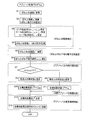
- Control program The control of the absorber 20 provided corresponding to each wheel 10 in the vehicle absorber system of the present embodiment is such that the computer 82 of the controller 80 executes the absorber control program whose flowchart is shown in FIG. Is done by. Incidentally, this program is repeatedly executed at a short time pitch (for example, several to several tens of milliseconds).
- a short time pitch for example, several to several tens of milliseconds.
- step 1 the sprung acceleration a (a fL , a fR , a rL , a corresponding to each wheel 10 is determined .
- rR the sprung speed v S corresponding to each wheel 10 is obtained by calculation based on the acquired sprung acceleration a.
- the sprung speed v S is obtained by performing an integration process on the acquired sprung acceleration a.
- the pitch component due a _P sprung acceleration a is heave due ingredient a _P is identified.
- the springs have been obtained previously acceleration a (a fL, a fR, a rL, a rR) and, the According to the equations (6) to (10), the front wheel side pitch- derived component a f_P and the rear wheel side pitch- derived component a r_P are specified, and the vehicle body lateral acceleration a Y detected by the vehicle body lateral acceleration sensor 90 acquired by being sprung acceleration a (a fL, a fR, a rL, a rR) based on the according to the above formula (11) to (15), the left wheel side roll due ingredient a L_R, the right wheel side roll due
- the component a r_P is specified, and further, based on the previously
- next S7 it is determined whether the product of the sprung speed v S and the sprung unsprung relative speed v S / US corresponding to each wheel 10 is positive or negative.
- the sprung motion direction is upward and the sprung unsprung relative motion direction is the approaching direction, or the sprung motion direction is the downward direction.
- the unsprung and unsprung relative movement direction is the separation direction, and in S8, the absorber force acting state is recognized as the propulsive force acting state.
- the product value is determined to be negative, that is, when it is determined not to be positive, the sprung operating direction is the downward direction and the unsprung relative movement direction is the approaching direction.
- the absorber force acting state is the resistance force acting state. Certified.
- the processing of S7 to S9 can be considered as processing for determining the absorber force acting state.
- the target damping coefficient C * of the absorber 20 corresponding to the wheel 10 is the minimum damping coefficient in the set range.
- the minimum attenuation coefficient C MIN that is C is determined.
- the target damping coefficient C * of the absorber 20 corresponding to the wheel 10 is The larger the sprung speed v S corresponding to the wheel 10 is, the larger the value is determined. That is, the processing of S10 and S11 can be considered as processing for determining the target damping coefficient C * as the target absorber force index. Although omitted in the flowchart, the processing of S7 to S11 is performed for each wheel 10.
- the target supply current I * which is the target of the supply current I to the absorber 20 arranged corresponding to each wheel 10, is determined for each wheel 10, and in S13, it is determined for each wheel 10.
- a signal regarding the target supply current I * is transmitted to the driver 84 corresponding to the variable valve 28 of each absorber 20. After the transmission of the signal, one execution of the program ends.
- Each driver 84 operates so that the current I supplied to the variable valve 28 functioning as the absorber force changing mechanism of each absorber 20 becomes the target supply current I *. Under the operation, each absorber 20 A suitable damping force is generated in the upper vibration suppression control. Therefore, the processes of S12 and S13 can be considered as processes for controlling the absorber force changing mechanism.
- the controller 80 includes the computer 82 and the four drivers 84 corresponding to the variable valves 28 of the respective absorbers 20.
- the computer 82 includes four drivers 84 corresponding to the respective wheels 10.
- the sprung acceleration sensor 86, the vehicle body longitudinal acceleration sensor 88, and the vehicle body lateral acceleration sensor 90 are connected to each other so as to be able to receive detection signals from them.
- Each driver 84 is connected to the battery 78 to receive a current therefrom, and is connected to the variable valve 28 of the corresponding absorber 20 to supply a current thereto.
- the computer 82 has several functional units that each function or are realized by execution of an absorber control program (hereinafter sometimes simply referred to as “control program”). Specifically, a sprung acceleration correction unit 100, a relative motion direction estimation unit 102, a sprung speed calculation unit 104, an absorber force action state determination unit 106, a target absorber force index determination unit 108, and a target supply current determination unit 110 are provided. is doing.
- control program an absorber control program
- the sprung acceleration correction unit 100 includes a pitch-derived component specifying unit 112, a roll-derived component specifying unit 114, a heave-derived component specifying unit 116, and a component exclusion processing unit 118, each of which is a subordinate functional unit. Yes.
- Pitch due component identifying section 112 the pitch component due a _P sprung acceleration a, particularly, the ability to identify the front-wheel-side pitch due ingredient a F_p and the rear wheel side pitch due ingredient a R_p, roll due component identifying section 114 a roll component due a _R sprung acceleration a, particularly, the function of identifying the left-wheel side roll due ingredient a L_R and the right-wheel-side pitch due ingredient a r_r, roll due component identifying section 116, the sprung acceleration a Have the function of specifying the heave-derived component a_H .
- These three specifying units 112, 114, and 116 are functional units realized by the process of S3 of the control program.
- the component exclusion processing unit 118 performs processing for excluding the three types of components specified by the three specifying units 112, 114, and 116 from the sprung acceleration a acquired based on the detection value of the sprung acceleration sensor 86.
- This is a functional unit that has a function to be performed and is realized by the process of S4 of the control program.
- the relative motion direction estimation unit 102 includes a sprung jerk calculating unit 120 and a sprung unsprung relative speed calculating unit 122, which are lower functional units.
- the sprung jerk calculating unit 120 has a function of performing a differentiation process on the corrected sprung acceleration a to obtain the sprung jerk a ′, and is a functional unit realized by the process of S5 of the control program.
- the sprung unsprung relative speed calculation unit 122 has a function of obtaining a sprung unsprung relative speed v S / US corresponding to each wheel 10 based on the acquired sprung jerk a ′. This is a functional unit realized by the process.
- the obtained sprung unsprung relative speed v S / US can be estimated based on whether the value of the sprung unsprung relative movement is the approaching direction or the separating direction. Obtaining v S / US can be considered as estimating the unsprung unsprung relative motion direction. For this reason, a functional unit including the sprung jerk calculating unit 120 and the unsprung unsprung relative speed calculating unit 122 is named a “relative motion direction estimating unit”. As described above, the calculation of the sprung unsprung relative speed v S / US based on the sprung jerk a ′ is equivalent to processing by a filter, specifically, processing by a primary low-pass filter. The unsprung unsprung relative speed calculation unit 122 can be considered as a part that functions as a filter.
- the sprung speed calculation unit 104 has a function of obtaining a sprung speed v S corresponding to each wheel 10 by integrating the sprung acceleration a acquired by the detection of the sprung acceleration sensor 86, and This is a functional unit realized by the processing of S2. Sprung velocity v S obtained, depending positive or negative it value, since the sprung operating direction can be estimated whether the downward direction or an upward direction, to obtain the sprung velocity v S is sprung operation direction Can be considered to be estimated.
- the absorber force acting state determination unit 106 includes a sprung unsprung motion direction estimated by the relative motion estimator 102 and a sprung motion direction estimated from the sprung motion speed v S calculated by the sprung speed calculator 104. Based on the above, it has a function of determining whether the absorber force acting state is the resistance force acting state or the propulsive force acting state. Specifically, the product of the sprung unsprung relative speed v S / US and the sprung speed sprung speed v S is expressed as “SIGN (v S / US ⁇ v S )” in the figure. Is output.
- the absorber force action state determination unit 106 is a functional unit realized by the processing of S7 to S9 of the control program.
- the target absorber force index determination unit 108 has a function of determining a target damping coefficient C * as a target absorber force index corresponding to each wheel 10 based on the sprung speed v S and the absorber force acting state. In short, the target absorber force index determination unit 108 determines the target damping coefficient C * to be the minimum damping coefficient C MIN when it is in the driving force acting state, and when it is in the resistive force acting state, the spring A value corresponding to the upper speed v S is determined.
- the target absorber force index determination unit 108 is a functional unit realized by the processing of S10 and S11 of the control program.
- the target supply current determination unit 110 determines the target supply current I * as a target value of the current supplied to the variable valve 28 of the absorber 20 corresponding to each wheel 10 based on the determined target damping coefficient C *.
- This is a functional unit that has a function and is realized by the processing of S12 of the control program.
- a signal about the target supply current I * is sent to each driver 84, and each driver 84 supplies a current of a magnitude corresponding to the signal to the variable valve 28 of the absorber 20 corresponding to itself. Therefore, it is considered that the absorber force change mechanism control unit 124 that includes the target supply current determination unit 110 and the driver 84 and controls the variable valve 28 that is the absorber force change mechanism based on the target damping coefficient C * is configured. be able to.
- the target absorber force index can also be considered as the target supply current I * .
- the target absorber force index determination unit 108 is configured including the target supply current determination unit 110, and the absorber force change mechanism control unit 124 includes only the driver 84. Will be configured.
- the hydraulic absorber 20 has been used in a double wishbone type suspension device.
- the vehicle absorber system according to the claimable invention can be applied to other types of suspension devices.
- the absorber may be employed in various types of suspension devices such as a strut mount type (MacPherson type), a multilink type, and a trailing arm type.
- the electromagnetic variable valve 28 is an example of an absorber force changing mechanism. As described above, the electromagnetic variable valve 28 includes a poppet valve as a main component. However, the absorber is another type of absorber force changing mechanism. For example, you may provide the absorber force change mechanism of a kind different from the variable valve 28 in the principle which changes damping force. For example, the absorber force changing mechanism may be configured to change the damping force by changing the resistance given to the flow of the working fluid by changing the cross-sectional area of the flow path through which the working fluid flows.
- the sprung acceleration a based upon sprung unsprung relative movement direction of the estimation is excluded pitch due ingredient a _P, roll due ingredient a _R, the three components of the heave component due a _H By doing so, correction is performed. So instead of excluding three components, the pitch due ingredient a _P, roll due ingredient a _R, by excluding only any one or any two of the heave component due a _H, The sprung acceleration a may be corrected.
- the vehicle absorber system according to the claimable invention does not exclude a system in which the sprung unsprung relative motion direction is estimated without correcting the sprung acceleration a.
- the controller 80 has a computer 82 as a main component and is configured to control the absorber 20 when the computer 82 executes a program.
- the controller in the vehicle absorber system according to the claimable invention is Alternatively, a dedicated logic circuit that performs analog or digital processing may be used as a main component, and the absorber 20 may be controlled without executing a program. Moreover, what is called a sequencer may be used.
Abstract
実用性の高い車両用アブソーバシステムを提供することを課題とする。 アブソーバ力を変更するための機構を有する液圧式ショックアブソーバ20と、そのショックアブソーバを制御するコントローラ80とを備えた車両用アブソーバシステムを、コントローラが、ばね上加速度aに基づいてばね上ばね下相対動作方向vS/USを推定し(102)、その推定された方向に基づいて、アブソーバ力を制御するように構成する(104,106,108,110)。 ばね上ばね下相対動作方向の推定にあたって、例えば、ばね上ばね下相対動作速度vS/USを検出するための専用のセンサや、オブザーバといった高度な推定手段を必要としないため、簡便な車両用アブソーバシステムが実現される。
Description
本発明は、液圧式ショックアブソーバを主要構成要素として車両に搭載される車両用アブソーバシステムに関する。
液圧式ショックアブソーバの制御に関して、例えば、下記特許文献に記載されているように、ばね上部とばね下部との相対動作の速度(以下、「ばね上ばね下相対速度」と言う場合がある)に基づいて、ショックアブソーバが発生させる減衰力を変更する技術が存在する。下記特許文献に記載されている技術では、ばね上ばね下相対速度を、荷重センサを利用して検出し、その検出したばね上ばね下相対速度を利用して、ばね上部とばね下部との相対動作の方向(以下、「ばね上ばね下相対動作方向」と言う場合がある)を把握し、その把握に基づいて減衰力の切換えを行っている。
液圧式ショックアブソーバが発生させる力(以下、「アブソーバ力」と言う場合がある)を、ばね上ばね下相対動作方向に基づいて制御することは、車両の乗り心地等の向上にとって有意義であり、その方向をある程度正確に把握することが望ましい。そのため、従来は、上記特許文献に記載の技術のようにばね上ばね下相対速度の検出のための専用のセンサを設けたり、いわゆるオブザーバと呼ばれる高度な推定手段を採用したりして、ばね上ばね下相対動作方向を把握していた。しかしながら、そのようなセンサ,オブザーバ等の採用は、ショックアブソーバとそれを制御するコントローラとを含んで構成される車両用アブソーバシステム全体のコストアップに繋がるといった問題を抱え、実用性という観点において必ずしも満足できるものとはなっていない。本発明は、そのような実情に鑑みてなされたものであり、実用性の高い車両用アブソーバシステムを提供することを課題とする。
上記課題を解決するために、本発明の車両用アブソーバシステムは、アブソーバ力を変更するための機構を有する液圧式ショックアブソーバと、そのショックアブソーバを制御するコントローラとを備え、そのコントローラが、ばね上加速度に基づいてばね上ばね下相対動作方向を推定し、その推定された方向に基づいて、アブソーバ力を制御するように構成されている。
本発明の車両用アブソーバシステムによれば、コントローラが、ばね上加速度に基づいてばね上ばね下相対動作方向を推定し、その推定されたばね上ばね下相対動作方向に基づいてアブソーバ力が制御されることになる。ばね上ばね下相対動作方向の推定にあたって、例えば、ばね上ばね下相対動作速度を検出するための専用のセンサや、オブザーバといった高度な推定手段を必要としないため、簡便な車両用アブソーバシステムが実現されることになる。その結果として、本発明の車両用アブソーバシステムは、実用性の高いものとなる。
以下に、本願において特許請求が可能と認識されている発明(以下、「請求可能発明」という場合がある)の態様をいくつか例示し、それらについて説明する。各態様は特許請求の範囲と同様に、項に区分し、各項に番号を付し、必要に応じて他の項の番号を引用する形式で記載する。これは、あくまでも請求可能発明の理解を容易にするためであり、それらの発明を構成する構成要素の組み合わせを、以下の各項に記載されたものに限定する趣旨ではない。つまり、請求可能発明は、以下の各項に付随する記載,実施形態の記載等を参酌して解釈されるべきであり、その解釈に従う限りにおいて、各項の態様にさらに他の構成要素を付加した態様も、また、各項の態様から何某かの構成要素を削除した態様も、請求可能発明の一態様となり得るのである。
なお、以下の各項において、(1)項~(8)項が、請求項1~請求項8に、それぞれ相当する。
(1)車両のばね上部とばね下部とを繋ぐように配設され、自身が発生させる力であるアブソーバ力をばね上部とばね下部との相対動作に対する減衰力として作用させるとともに、そのアブソーバ力を変更するためのアブソーバ力変更機構を有する液圧式ショックアブソーバと、
前記液圧式ショックアブソーバを制御するコントローラと
を備えた車両用アブソーバシステムであって、
前記コントローラが、
ばね上部の上下方向の加速度であるばね上加速度に基づいて、ばね上部とばね下部との相対動作の方向であるばね上ばね下相対動作方向が、ばね上部とばね下部とが互いに離間する方向である離間方向であるか、互いに接近する方向である接近方向であるかを推定する相対動作方向推定部を有し、前記推定されたばね上ばね下相対動作方向に基づいて、前記アブソーバ力変更機構を制御するように構成された車両用アブソーバシステム。
前記液圧式ショックアブソーバを制御するコントローラと
を備えた車両用アブソーバシステムであって、
前記コントローラが、
ばね上部の上下方向の加速度であるばね上加速度に基づいて、ばね上部とばね下部との相対動作の方向であるばね上ばね下相対動作方向が、ばね上部とばね下部とが互いに離間する方向である離間方向であるか、互いに接近する方向である接近方向であるかを推定する相対動作方向推定部を有し、前記推定されたばね上ばね下相対動作方向に基づいて、前記アブソーバ力変更機構を制御するように構成された車両用アブソーバシステム。
本態様によれば、ばね上ばね下動作方向(「ばね上部とばね下部との上下方向における相対移動の方向」と考えることもできる)の推定にあたって、例えば、ばね上ばね下相対動作速度を検出するための専用のセンサや、オブザーバといった高度な推定手段を必要としないため、簡便な車両用アブソーバシステムが実現されることになる。言い換えれば、ばね上加速度以外の情報を外部から取得することなしに、ばね上ばね下動作方向を推定することで、例えば、ばね上部とばね下部との上下方向における相対変位量を検出するためのセンサ(例えば、「ストロークセンサ」)等が必要とされないのである。つまり、ばね上加速度のみに基づいてばね上ばね下動作方向を推定することで、そのような利点を充分に享受することができるのである。なお、ばね上加速度は、例えば、ばね上部にばね上加速度センサを設けることによって、簡単に取得できる。ちなみに、ばね上加速度センサは、上記ストロークセンサに比較して、車両に簡単に搭載することが可能である。
なお、ショックアブソーバが発生させるアブソーバ力FAは、ばね上ばね下相対速度vS/USに依存しており、簡単には、
FA=C・vS/US C:減衰係数
と、表すことができる。したがって、アブソーバ力を比較する場合等においては、同じばね上ばね下相対速度であることが前提となる。そのことに鑑みて、本明細書におけるアブソーバ力の大小は、減衰力特性の相違、具体的には、減衰係数の大小を意味することがあることとし、また、アブソーバ力の変更は、減衰力特性の変更、具体的には、減衰係数の変更を意味することがあることとする。
FA=C・vS/US C:減衰係数
と、表すことができる。したがって、アブソーバ力を比較する場合等においては、同じばね上ばね下相対速度であることが前提となる。そのことに鑑みて、本明細書におけるアブソーバ力の大小は、減衰力特性の相違、具体的には、減衰係数の大小を意味することがあることとし、また、アブソーバ力の変更は、減衰力特性の変更、具体的には、減衰係数の変更を意味することがあることとする。
(2)前記相対動作方向推定部が、ばね上加速度に基づいて、ばね上部の加加速度であるばね上加加速度を取得し、その取得されたばね上加加速度に基づいて、ばね上ばね下相対動作方向が離間方向であるか接近方向であるかを推定するように構成された(1)項に記載の車両用アブソーバシステム。
本態様は、ばね上ばね下動作方向の推定の手法について限定を加えた態様である。「加加速度」は、「ジャーク」と呼ぶこともできる。ばね上加加速度は、ばね上加速度を微分処理等することによって簡単に取得することが可能である。ばね上加加速度に基づくことで、ばね上ばね下相対動作方向を、アビソーバ力制御において充分な程度正確に推定することが可能である。
(3)前記相対動作方向推定部が、ばね上加加速度が入力されることによってばね上部とばね下部との相対動作の速度であるばね上ばね下相対速度が出力されるフィルタとして機能する部分を有し、その出力されたばね上ばね下相対動作速度に基づいて、ばね上ばね下相対動作方向が離間方向であるか接近方向であるかを推定するように構成された(2)項に記載の車両用アブソーバシステム。
例えば、ばね上加加速度に基づくことにより、ばね上部とばね下部との動作に関するモデル(「振動モデル」と考えることもできる)に従って、ばね上ばね下相対速度を容易に導出することができ、そのように導出されたばね上ばね下相対速度を利用することで、ある程度正確なばね上ばね下相対動作方向の推定が可能となる。端的に言えば、いわゆるオブザーバのような高度,複雑なアルゴリズムに従った処理を行わずして、ばね上ばね下相対動作方向の推定が可能となるのである。本態様は、そのような観点から、上記ばね上ばね下相対速度の導出の手法に限定を加えた態様であり、本態様によれば、上記フィルタが行う処理(例えば、1次ローパスフィルタ」が行う処理)によって、容易に、ばね上加加速度に基づいてばね上ばね下相対速度を求めることが可能である。
(4)前記相対動作方向推定部が、前記液圧式ショックブソーバが発揮すべき標準的な減衰力特性を指標するものとして設定された設定標準特性指標を利用して、ばね上ばね下相対動作方向が離間方向であるか接近方向であるかを推定するように構成された(1)項ないし(3)項のいずれか1つに記載の車両用アブソーバシステム。
本項にいう「減衰力特性」は、減衰力の大きさを示すものと考えることができ、例えば、ショックアブソーバの「減衰係数」等が該当する。上記設定標準特性指標は、車両の設計思想等に基づいて設定されるその車両固有の固定的な値を持つものと考えることができる。ショックアブソーバの発生させるアブソーバ力は上記アブソーバ力変更機構によって変更可能とされているため、実際の減衰力特性は変化することになる。本態様によれば、そのような変化があるにも拘わらず、敢えて、減衰力特性として標準的な固定の値を採用することで、簡便に、かつ、制御における要求を充分に満たす程の正確さで、ばね上ばね下相対動作方向を推定することが可能となる。
(5)前記コントローラが、
それぞれがばね上加速度の一成分であるところの (a)車体のピッチ動作に起因する成分であるピッチ起因成分, (b)車体のロール動作に起因する成分であるロール起因成分, (c)車体のヒーブ動作に起因する成分であるヒーブ起因成分の少なくとも1つを除外するようにして、ばね上加速度を補正するばね上加速度補正部を有し、
前記相対動作方向推定部が、前記補正されたばね上加速度に基づいて、ばね上ばね下動作方向が離間方向であるか接近方向であるかを推定するように構成された(1)項ないし(4)項のいずれか1つに記載の車両用アブソーバシステム。
それぞれがばね上加速度の一成分であるところの (a)車体のピッチ動作に起因する成分であるピッチ起因成分, (b)車体のロール動作に起因する成分であるロール起因成分, (c)車体のヒーブ動作に起因する成分であるヒーブ起因成分の少なくとも1つを除外するようにして、ばね上加速度を補正するばね上加速度補正部を有し、
前記相対動作方向推定部が、前記補正されたばね上加速度に基づいて、ばね上ばね下動作方向が離間方向であるか接近方向であるかを推定するように構成された(1)項ないし(4)項のいずれか1つに記載の車両用アブソーバシステム。
例えば、ばね上部に設けられたばね上加速度センサによって検出されたばね上加速度には、車体のピッチ動作,ロール動作,ヒーブ動作に起因する成分が含まれており、ばね上ばね下相対動作方向を推定するにあたっては、それらの成分を除外することで、より正確な推定が可能となる。本態様では、そのような観点から、ばね上加速度を補正に関する限定が加えられている。なお、本態様には、ピッチ起因成分,ロール起因成分,ヒーブ起因成分のすべてを除外するような補正を行う態様も、また、それらの成分のうちの任意の1つまたは2つを除外するような補正を行う態様も含まれる。
(6)前記コントローラが、
前記推定されたばね上ばね下相対動作方向と、ばね上部の動作の方向であるばね上動作方向とに基づいて、ばね上部に対してアブソーバ力が作用する状態であるアブソーバ力作用状態が、アブソーバ力がばね上部の動作の抵抗となる方向に作用する抵抗力作用状態であるか、ばね上部の動作を推進する方向に作用する推進力作用状態であるかを判断するアブソーバ力作用状態判断部と、
ばね上部の動作を減衰させるべく、前記判断されたアブソーバ力作用状態に基づいて、発生させるべきアブソーバ力を指標する目標アブソーバ力指標を決定する目標アブソーバ力指標決定部と、
前記決定された目標アブソーバ力指標に基づいて、前記アブソーバ力変更機構を制御するアブソーバ力変更機構制御部と
を有する(1)項ないし(5)項のいずれか1つに記載の車両用アブソーバシステム。
後に詳しく説明するように、液圧式ショックアブソーバは、ばね上ばね下相対動作に対する減衰力すなわち抵抗力を発生するものであり、ばね上部の動作(「ばね上部の移動」と考えることもできる)、つまり、ばね上部の振動を減衰させようとする場合に、ばね上動作方向とばね上ばね下動作方向との如何によっては、必ずしも、アブソーバ力はばね上動作の抵抗力とはならない。そのような観点から、本態様は、ばね上部の動作を減衰させる制御、つまり、ばね上制振制御を行うための具体的な構成に関する限定を加えた態様である。本態様によれば、ばね上ばね下動作方向とばね上動作方向とに基づいてアブソーバ力作用状態が判断され、その判断に基づいてアブソーバ力が制御されるため、ばね上部の振動を効果的に減衰させることが可能となる。
なお、本項にいう「目標アブソーバ力指標」は、発生させるべきアブソーバ力そのものであってもよく、ショックアブソーバが有するべき減衰係数,供給電流等のアブソーバ力変更機構の制御においてその機構に出力される物理量(物理的パラメータ,制御出力等と呼ぶこともできる)の目標値等、種々のものを、目標アブソーバ力指標として、採用可能である。
(7)前記目標アブソーバ力指標決定部が、前記判断されたアブソーバ力作用状態が推進力作用状態である場合に、通常におけるアブソーバ力の範囲として設定された設定範囲内においてアブソーバ力を最も小さくすべく、目標アブソーバ力指標を決定するように構成された(6)項に記載の車両用アブソーバシステム。
本態様によれば、推進力作用状態においてアブソーバ力が可及的に小さくされるため、そのアブソーバ力がばね上部の振動の減衰を阻害することを可及的に抑制され、その結果、より効果的にばね上部の振動を減衰させることが可能となる。なお、「設定範囲」は、制御において発生させられるアブソーバ力の範囲、言い換えれば、制御においてショックアブソーバが持ち得る減衰係数の範囲と考えることができる。
(8)前記目標アブソーバ力指標決定部が、前記判断されたアブソーバ力作用状態が抵抗力作用状態である場合に、ばね上部の動作の速度であるばね上速度が大きい程前記設定範囲内においてアブソーバ力を大きくすべく、目標アブソーバ力指標を決定するように構成された(6)項または(7)項に記載の車両用アブソーバシステム。
本態様によれば、抵抗力作用状態において、ばね上速度が大きい程、より大きな抵抗力としてアブソーバ力が発生させられることとなり、その結果、より効果的にばね上部の振動を減衰させることが可能となる。
以下、請求可能発明の代表的な実施形態を、実施例として、図を参照しつつ詳しく説明する。なお、請求可能発明は、下記実施例の他、前記〔発明の態様〕の項に記載された態様を始めとして、当業者の知識に基づいて種々の変更、改良を施した種々の態様で実施することができる。また、〔発明の態様〕の各項の説明に記載されている技術的事項を利用して、下記の実施例の変形例を構成することも可能である。
実施例の車両用アブソーバシステムは、車両の前後左右の各輪に対応して設けられた4つの液圧式ショックアブソーバと、それらを制御するコントローラとを含んで構成されている。以下に、液圧式ショックアブソーバの構成および作用,コントローラによる液圧式ショックアブソーバの制御について、順次、説明する。
[A]液圧式ショックアブソーバの構成および作用
i)液圧式ショックアブソーバが採用されるサスペンション装置
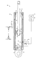
液圧式ショックアブソーバ(以下、単に「アブソーバ」と言う場合がある)は、図1に示すように、サスペンション装置の一構成要素として機能するものである。図に示すサスペンション装置は、実施例の車両用アブソーバシステムを構成する液圧式ショックアブソーバ(以下、「実施例の液圧式ショックアブソーバ」若しくは「実施例のアブソーバ」と言う場合がある)を採用可能なサスペンション装置の一例であり、ダブルウィッシュボーン型のサスペンション装置である。このサスペンション装置は、車輪10を回転可能に保持するキャリア12と、それぞれが車体のサイドメンバー14とキャリア12とをそれらの各々に対して回動可能な状態で連結する2つのサスペンションアーム、詳しくは、ロアアーム16およびアッパアーム18とを含んで構成されており、液圧式ショックアブソーバ20は、タイヤハウジングの上部において車体に設けられたマウント部22とロアアーム16とを連結するように配設されている。また、アブソーバ20にはスプリングシート24が固定されており、マウント部22とスプリングシート24との間に挟まれるようにして、サスペンション装置の一構成要素としてのサスペンションスプリング26が配設されている。なお、図に示すサスペンション装置は、転舵されない車輪10に対する装置であり、転舵輪に対する装置の場合は、キャリア12に代えて、ステアリングナックルが採用される。
i)液圧式ショックアブソーバが採用されるサスペンション装置
液圧式ショックアブソーバ(以下、単に「アブソーバ」と言う場合がある)は、図1に示すように、サスペンション装置の一構成要素として機能するものである。図に示すサスペンション装置は、実施例の車両用アブソーバシステムを構成する液圧式ショックアブソーバ(以下、「実施例の液圧式ショックアブソーバ」若しくは「実施例のアブソーバ」と言う場合がある)を採用可能なサスペンション装置の一例であり、ダブルウィッシュボーン型のサスペンション装置である。このサスペンション装置は、車輪10を回転可能に保持するキャリア12と、それぞれが車体のサイドメンバー14とキャリア12とをそれらの各々に対して回動可能な状態で連結する2つのサスペンションアーム、詳しくは、ロアアーム16およびアッパアーム18とを含んで構成されており、液圧式ショックアブソーバ20は、タイヤハウジングの上部において車体に設けられたマウント部22とロアアーム16とを連結するように配設されている。また、アブソーバ20にはスプリングシート24が固定されており、マウント部22とスプリングシート24との間に挟まれるようにして、サスペンション装置の一構成要素としてのサスペンションスプリング26が配設されている。なお、図に示すサスペンション装置は、転舵されない車輪10に対する装置であり、転舵輪に対する装置の場合は、キャリア12に代えて、ステアリングナックルが採用される。
上記のようなサスペンション装置の構造から、当該車両においては、マウント部22等を含んで当該車輪10に対応する「ばね上部」が構成され、車輪10,キャリア12等によって、「ばね下部」が構成されることとなる。したがって、実施例のアブソーバ20は、車両のばね上部とばね下部とを繋ぐように配設され、自身が発生させる力であるアブソーバ力を、車輪10の車体に対する上下動(「車体の車輪10に対する上下動」と考えることもできる)、つまり、ばね上部とばね下部との相対動作に対する減衰力として作用させるものとなっている。そして、後に詳しく説明するが、アブソーバ20は、アブソーバ力を変更するためのアブソーバ力変更機構としての電磁式可変弁28(以下、単に「可変弁28」という場合がある)を有している。
ii)液圧式ショックアブソーバの構造
液圧式ショックアブソーバ20は、図2に示すように、ハウジング30と、ハウジング30の内部において上下方向に移動可能に配設されたピストン32と、一端部(下端部)がピストン32に連結されて他端部(上端部)がハウジング30から上方に延び出すロッド34とを含んで構成されている。ハウジング30の下端には連結部材36が付設されており、ハウジング30は、その連結部材36を介して、ロアアーム16に連結されている。一方、雄ねじが形成されているロッド34の上端部は、その雄ねじを利用して、マウント部22に、連結されている。つまり、アブソーバ20は、車両のばね上部とばね下部とを繋ぐようにして配設されているのである。したがって、アブソーバ20は、ばね上部とばね下部の上下方向の相対移動(相対動作)、つまり、ばね上部とばね下部との離間,接近に伴って、伸縮する。詳しく言えば、ばね上部とばね下部とが離間する方向に相対移動する場合(以下、「リバウンド動作時」若しくは「リバウンド時」と言う場合がある)に伸長し、接近する方向に相対移動する場合(以下、「バウンド動作時」若しくは「バウンド時」と言う場合がある)に収縮する。
液圧式ショックアブソーバ20は、図2に示すように、ハウジング30と、ハウジング30の内部において上下方向に移動可能に配設されたピストン32と、一端部(下端部)がピストン32に連結されて他端部(上端部)がハウジング30から上方に延び出すロッド34とを含んで構成されている。ハウジング30の下端には連結部材36が付設されており、ハウジング30は、その連結部材36を介して、ロアアーム16に連結されている。一方、雄ねじが形成されているロッド34の上端部は、その雄ねじを利用して、マウント部22に、連結されている。つまり、アブソーバ20は、車両のばね上部とばね下部とを繋ぐようにして配設されているのである。したがって、アブソーバ20は、ばね上部とばね下部の上下方向の相対移動(相対動作)、つまり、ばね上部とばね下部との離間,接近に伴って、伸縮する。詳しく言えば、ばね上部とばね下部とが離間する方向に相対移動する場合(以下、「リバウンド動作時」若しくは「リバウンド時」と言う場合がある)に伸長し、接近する方向に相対移動する場合(以下、「バウンド動作時」若しくは「バウンド時」と言う場合がある)に収縮する。
ピストン32は、ハウジング30の内部を摺接して移動可能とされており、ハウジング30の内部には、ピストン32によって、それぞれが作動液で満たされた2つの液室40,42が区画形成されている。詳しく言えば、ピストン32の上方に位置してロッド34が貫通するロッド側室40と、ピストン32の下方に位置する反ロッド側室42とが、それぞれ区画形成されている。それら2つの液室40,42は、アブソーバ20の伸縮に伴って、つまり、ばね上部とばね下部との相対移動に伴って、容積が変化する。詳しく言えば、リバウンド動作時には、ロッド側室40の容積が減少し、反ロッド側室42の容積が増加する。一方、バウンド動作時には、ロッド側室40の容積が増加し、反ロッド側室42の容積が減少する。
ハウジング30は、概して3重構造をなしており、最も内周側に存在する有底のメインチューブ44と、メインチューブ44の外周部に付設されて最も外周側に存在するアウタチューブ46と、メインチューブ44にそれを取り巻くように付設されてそれらメインチューブ46とアウターチューブ46との間に存在するインタチューブ48とを有している。メインチューブ44の内周面によって、ロッド側室40および反ロッド側室42の周囲が区画されており、メインチューブ44の外周面およびインタチューブ48の外周面とアウタチューブ46の内周面との間には、それらによって、作動液を収容する環状のバッファ室50が区画形成されている。ちなみに、バッファ室50は、ロッド側室40および反ロッド側室42の外部において作動液を貯留するリザーバとして機能するものであり、リザーバ室と呼ぶこともできるものである。ロッド34の存在により、ロッド側室40と反ロッド側室42との合計容積は、リバウンド時には、増加し、バウンド時には、減少する。バッファ室50は、ロッド側室40と反ロッド側室42とに作動液を充満させた状態でのそれら合計容積の変化を許容するために設けられた液室である。
メインチューブ44の内底部には、反ロッド側室42の底を区画する仕切部材52が設けられており、仕切部材52とメインチューブ44の底壁との間には、底部液通路54が形成されている。一方、インタチューブ48の内周面とメインチューブ44の外周面との間には、環状をなす環状液通路56が区画形成されている。
メインチューブ44の上端に近い部分には、環状液通路56とロッド側室40との間の作動液の流通を担保するために、上部流通穴58が設けられており、メインチューブ44の下端に近い部分には、バッファ室50と底部液通路54との間の作動液の流通を担保するために、下部流通穴60が設けられている。インタチューブ48の下部には、環状液通路56からの作動液の流出を許容する流出口62が、アウタチューブ46には、流出口62と同軸的に位置して、バッファ室50への作動液の流入を許容する流入口64が、それぞれ設けられている。
また、図に模式的に示すように、ピストン32には、ロッド側室40と反ロッド側室42とを連通させる液通路66が形成されており、その液通路66に、逆子弁68が設けられている。この逆止弁68の機能により、反ロッド側室42からロッド側室40への作動液の流れが、殆ど抵抗を受けることなく許容されるとともに、ロッド側室40から反ロッド側室42への作動液の流れが禁止される。一方、図に模式的に示すように、仕切部材52には、反ロッド側室42と底部液通路54とを連通させる液通路70が形成されており、その液通路70にも、逆子弁72が設けられている。この逆止弁72の機能により、底部液通路54を介したバッファ室50から反ロッド側室42への作動液の流れが、殆ど抵抗を受けることなく許容されるとともに、底部液通路54を介した反ロッド側室42からバッファ側室50への作動液の流れが禁止される。
上述の可変弁28は、上記流出口62および上記流入口64を覆うようにして配設されており、環状液通路56からバッファ室50に流入する作動液の通過を許容するともに、その作動液の流れに対して抵抗を与える機能を有している。詳しい構造についての説明は省略するが、可変弁28は、ポペット弁とソレノイドとを主体として構成され、その弁を挟んだ流路の上流側と下流側の作動液の差圧を、ソレノイドのコイルが発生させる電磁力によって調整すべく、開弁圧(閉弁圧)を変更するように構成されている。可変弁28は、自身に供給される電流(以下、「供給電流」という場合がある)が大きくなる程、開弁圧(閉弁圧)が高くなるように構成されており、供給電流が大きい程、環状液通路56からバッファ室50に流入する作動液の流れに対する抵抗が大きくなる。
可変弁28への供給電流は、バッテリ78から供給される。可変弁28は、制御装置としてのコントローラ80(図2では〔CNT〕と表記されている)を介して、バッテリ78(図2では〔BAT〕と表記されている)に接続されており、可変弁28に供給される電流の制御は、そのコントローラ80によって行われる。つまり、アブソーバ20は、コントローラ80によって制御されるのである。ちなみに、コントローラ80は、コンピュータ82を主要構成要素をするものであり、可変弁28の駆動回路であるドライバ84を含んで構成されている。
iii)液圧式ショックアブソーバの作用
アブソーバ20が伸長する場合、つまり、ばね上部とばね下部とが互いに離間する方向である「離間方向」にそれらが相対動作する場合について考える。ばね上部とばね下部との相対動作を「ばね上ばね下相対動作」と呼べば、そのばね上ばね下相対動作の方向が離間方向であるとき、つまり、リバウンド動作時には、反ロッド側室42からロッド側室40への作動液の流れが禁止されるため、図に示すように、専ら、反ロッド側室42の容積の増加に伴い、バッファ室50から、底部液通路54を介して、その容積増加量に応じた作動液が、反ロッド側室42に流入し、ロッド側室40の容積減少に伴い、その容積減少量に応じた作動液が、ロッド側室40から、環状液通路56を介して、バッファ室50に流出する。リバウンド動作時には、そのロッド側室40からバッファ室50への作動液の流れに対して、可変弁28によって、抵抗が付与され、その抵抗に依拠したアブソーバ力が、リバウンド動作に対する減衰力として発生することになる。
アブソーバ20が伸長する場合、つまり、ばね上部とばね下部とが互いに離間する方向である「離間方向」にそれらが相対動作する場合について考える。ばね上部とばね下部との相対動作を「ばね上ばね下相対動作」と呼べば、そのばね上ばね下相対動作の方向が離間方向であるとき、つまり、リバウンド動作時には、反ロッド側室42からロッド側室40への作動液の流れが禁止されるため、図に示すように、専ら、反ロッド側室42の容積の増加に伴い、バッファ室50から、底部液通路54を介して、その容積増加量に応じた作動液が、反ロッド側室42に流入し、ロッド側室40の容積減少に伴い、その容積減少量に応じた作動液が、ロッド側室40から、環状液通路56を介して、バッファ室50に流出する。リバウンド動作時には、そのロッド側室40からバッファ室50への作動液の流れに対して、可変弁28によって、抵抗が付与され、その抵抗に依拠したアブソーバ力が、リバウンド動作に対する減衰力として発生することになる。
逆に、アブソーバ20が収縮する場合、つまり、ばね上部とばね下部とが互いに接近する方向である「接近方向」にそれらが相対動作する場合について考える。ばね上ばね下相対動作の方向が接近方向であるとき、つまり、バウンド動作時には、反ロッド側室42から底部液通路54を介したバッファ室50への作動液の流れが禁止され、かつ、反ロッド側室42の容積減少量がロッド側室40の容積増加量より大きいため、図に示すように、専ら、反ロッド側室42の容積の減少に伴い、その容積減少量に応じた作動液が、反ロッド側室42からロッド側40へ作動液が流出し、ロッド側室40の容積増加に伴い、反ロッド側室42の容積減少量からロッド側室40の容積増加量を減じた量に応じた作動液が、ロッド側室40から、環状液通路56を介して、バッファ室50に流出する。バウンド動作時においても、リバウンド動作時と同様、そのロッド側室40からバッファ室50への作動液の流れに対して、可変弁28によって、抵抗が付与され、その抵抗に依拠したアブソーバ力が、バウンド動作に対する減衰力として発生することになる。
上述したように、可変弁28への供給電流はコントローラ80によって制御されており、そのコントローラ80による制御の下、アブソーバ力が制御される。言い換えれば、ばね上ばね下相対動作に対する減衰力が制御されるのである。なお、先に説明したように、減衰力は、ばね上とばね下部との相対動作の速度である「ばね上ばね下相対速度」に依存するため、減衰力の制御は、厳密には、アブソーバ20の減衰力特性、つまり、発生させられる減衰力の基準としての「減衰係数」の制御を意味する。
[B]コントローラによる液圧式ショックアブソーバの制御
i)基本的な制御
本実施例の車両用アブソーバシステムでは、主にばね上部の振動を抑制する制御である「ばね上制振制御」が実行される。ばね上制振制御は、詳しく言えば、アブソーバ力を、ばね上部の動作(ばね上部の移動と考えることもできる)である「ばね上動作」に対する抵抗力として作用させることを原則とする制御であり、ばね上部の動作の速度である「ばね上速度」に応じたアブソーバ力を発生させるべく、可変弁12を制御する。さらに詳しく言えば、原則として、ばね上速度が大きくなる程、アブソーバ力を大きくすべく、設定範囲内において、当該アブソーバ20の減衰係数を大きくするように、可変弁28への供給電流を制御する。
i)基本的な制御
本実施例の車両用アブソーバシステムでは、主にばね上部の振動を抑制する制御である「ばね上制振制御」が実行される。ばね上制振制御は、詳しく言えば、アブソーバ力を、ばね上部の動作(ばね上部の移動と考えることもできる)である「ばね上動作」に対する抵抗力として作用させることを原則とする制御であり、ばね上部の動作の速度である「ばね上速度」に応じたアブソーバ力を発生させるべく、可変弁12を制御する。さらに詳しく言えば、原則として、ばね上速度が大きくなる程、アブソーバ力を大きくすべく、設定範囲内において、当該アブソーバ20の減衰係数を大きくするように、可変弁28への供給電流を制御する。
ここで、車両に振動が生じている場合、例えば、ばね上速度vS、および、ばね上ばね下相対速度vS/USは、図3に示すように変化する。図では、ばね上ばね下相対速度vS/USが0より大きくなっているときに、バウンド動作が行われていることを示しており、ばね上ばね下相対速度vS/USが0より小さくなっているときに、リバウンド動作が行われていることを示している。また、図では、ばね上速度vSが0より大きいときに、ばね上部が上方に移動していることを、ばね上速度vSが0より小さいときに、ばね上部が下方に移動していることを、それぞれ示している。
アブソーバ20は、ばね上ばね下相対動作に対する減衰力、つまり、抵抗力しか発生させることができないため、アブソーバ力がばね上動作に対する抵抗力として作用する状態である「抵抗力作用状態」が実現するには、ばね上動作の方向である「ばね上動作方向」が上方向である場合には、ばね上部とばね下部との相対動作の方向である「ばね上ばね下相対動作方向」が離間方向であること、若しくは、ばね上動作方向が下方向である場合には、ばね上ばね下動作方向が接近方向であることが必要とされる。したがって、図において“*”で示す領域は、ばね上動作方向が上方向でありばね上ばね下動作相対動作が接近方向である領域、若しくは、ばね上動作方向が下方向でありばね上ばね下動作相対動作が離間方向である領域であり、それらの領域では、抵抗力作用状態が実現しない。言い換えれば、それらの領域では、アブソーバ力がばね上部の動作を推進する方向に作用する状態である「推進力作用状態」となってしまうのである。
上記のことに鑑み、本車両用アブソーバシステムにおいて行われるばね上制振制御では、ばね上部に対してアブソーバ力が作用する状態、つまり、「アブソーバ力作用状態」が、推進力作用状態である場合には、ばね上速度の如何に拘わらず、アブソーバ力を相当に小さくなるように、可変弁28への供給電流が制御される。詳しく言えば、設定範囲内において減衰係数が最も小さくなるように供給電流が制御される。その一方で、抵抗力作用状態である場合には、上述の原則に従い、アブソーバ力がそれがばね上速度に応じた大きさとなるように、詳しくは、ばね上速度が大きいほど減衰係数が大きくなるように、可変弁28への供給電流が制御される。したがって、本実施例の車両用アブソーバシステムにおいて実行されるばね上制振制御では、アブソーバ力作用状態が抵抗力作用状態であるか推進力作用状態であるかが判断され、その判断されたアブソーバ力作用状態に基づいて、減衰係数の切換えが行われるのである。
減衰係数は、アブソーバ力を指標する「アブソーバ力指標」の一種であり、制御下においてアブソーバ20が有するべき減衰係数である「目標減衰係数」は、制御下においてアブソーバ20が発生させるべきアブソーバ力を指標する「目標アブソーバ指標」の一種となる。したがって、本実施例の車両用アブソーバシステムにおいて行われるばね上制振制御では、アブソーバ力作用状態に基づいて、目標アブソーバ力指標としての目標減衰係数を決定し、その決定された目標減衰係数に基づいて、アブソーバ力変更機構としての可変弁28が制御される。具体的に言えば、目標減衰係数に基づいて、可変弁28へ供給すべき電流である「目標供給電流」が決定され、その決定された目標供給電流を可変弁28に供給するような制御が行われるのである。
ii)ばね上ばね下相対動作方向の推定
アブソーバ力作用状態の判断にあたっては、ばね上動作方向と、ばね上ばね下相対動作方向とを正確に判断することが望まれる。サスペンション装置には、実施例の車両用ショックアブソーバシステムの一構成要素として、ばね上部の上下方向の加速度である「ばね上加速度」を検出するためのばね上加速度センサ86が、各車輪10に対応して設けられおり(図1,図9参照)、ばね上動作方向は、このセンサ86によって検出されたばね上加速度に基づいて、取得される。具体的には、例えば、刻々と変化するばね上加速度を積分することにより、ばね上速度を取得し、その取得されたばね上速度に基づいて、詳しくは、そのばね上速度の符合(正負)に基づいて、ばね上動作方向が判断される。
アブソーバ力作用状態の判断にあたっては、ばね上動作方向と、ばね上ばね下相対動作方向とを正確に判断することが望まれる。サスペンション装置には、実施例の車両用ショックアブソーバシステムの一構成要素として、ばね上部の上下方向の加速度である「ばね上加速度」を検出するためのばね上加速度センサ86が、各車輪10に対応して設けられおり(図1,図9参照)、ばね上動作方向は、このセンサ86によって検出されたばね上加速度に基づいて、取得される。具体的には、例えば、刻々と変化するばね上加速度を積分することにより、ばね上速度を取得し、その取得されたばね上速度に基づいて、詳しくは、そのばね上速度の符合(正負)に基づいて、ばね上動作方向が判断される。
一方で、サスペンション装置には、ばね上ばね下相対速度を検出するためのばね上ばね下相対速度センサ,ばね下部の加速度である「ばね下加速度」を検出するばね下加速度センサ等は設けられておらず、上記ばね上加速度センサ86によって検出されたばね上加速度に基づいて、各車輪10に対応するばね上ばね下相対動作方向が推定されるようになっている。以下に、そのばね上ばね下相対動作方向の推定について詳しく説明する。
当該車両におけるばね上部の振動モデルとして、つまり、1つの車輪,1つのサスペンション装置に対応した振動モデルとして、図4に示すようなモデルを考えることができる。図における“m”は、1つの車輪に対応したばね上重量(ばね上質量)であり、“x1”,“x2”は、それぞれ、ばね上部の基準位置からの変位量である「ばね上変位量」,ばね下部の基準位置からの変位量である「ばね下変位量」である。また、“k”は、サスペンションスプリング26のばね定数であり、“CN”は、当該車両においてアブソーバ20が有すべき標準的な減衰係数として設定された「設定標準減衰係数」であり、当該車両においてアブソーバ20が発揮すべき標準的な減衰力特性を指標するものとして設定された「設定標準特性指標」の一種である。アブソーバ20は、上述したように、可変弁28の作用により減衰係数Cが可変ではあるが、ばね上ばね下相対動作方向の推定では、その推定の処理を簡便かつ適切に行うために、設定標準減衰係数CNという固定的な減衰係数を有するアブソーバが採用された振動モデルを用いている。ちなみに、設定標準減衰係数CNは、当該車両においてサスペンション装置が有すべき特性として設定された「設定標準減衰比」から導きだされるものであり、その設定標準減衰比ζNは、例えば、柔らか目の乗り心地を目指した車両では、ζN=0.3、スポーティーな車両では、ζN=1.0、中庸な特性の車両では、ζN=0.7といった具合に設定された当該車両固有のものである。
図4のモデルに従えば、サスペンションスプリング26およびアブソーバ20からばね上部が受ける力、つまり、スプリング26およびアブソーバ20のばね上部への作用力である「対ばね上作用力F」は、ラプラス演算子sを用いて、下記式(1)で表すことができる。

そして、ばね上加速度を“a”とし、ばね上部に他の外力が加わらないとすれば、下記式(2)が成立する。なお、ばね上加速度aは、各輪ともに、上向きの場合に正の値をとるものとする。

上記式(1)および上記式(2)より、下記式(3)が得られる。

上記式(3)において、“a′”は、いわゆるばね上部の加加速度である「ばね上加加速度」であり、ばね上加速度aを微分処理して得られるものである。なお、加加速度は、「ジャーク」と呼ぶこともできる。また、(x2-x1)sは、ばね上ばね下相対速度vS/USに相当するものである。したがって、検出されたばね上加速度aに基づいてばね上加加速度a´を取得し、その取得されたばね上加加速度a′に基づいて、上記式(3)に従うことにより、ばね上ばね下相対速度vS/USを推定することができ、その結果として、ばね上ばね下相対動作方向が推定できるのである。つまり、ばね上ばね下相対速度vS/USを、ばね上ばね下相対動作方向を指標する「ばね上ばね下相対動作方向指標」として扱い、その指標に基づいて、ばね上ばね下相対動作方向が推定されるのである。本実施例の車両用アブソーバシステムにおいて行われるばね上制振制御では、アブソーバ力作用状態の判断に先立って、上述のようにしてばね上ばね下相対動作方向が推定される。
ここで、入力値VINとした場合において出力値VOUTが出力されるような伝達関数H(s)を考えれば、その伝達関数H(s)は、下記式(4)によって定義することができる。

また、伝達関数H(s)による上記式(4)の処理が、1次ローパスフィルタによる処理であると考えれば、上記式(4)は、ゲインG,時定数τを用いて、下記式(5)で表すことができる。

上記式(5)と上記式(3)とを比較すれば、上記式(3)に従う処理は、G=m/k,τ=CN/kとなる場合において、入力値VINとしてのばね上加加速度a′が入力された際に、出力値VOUTとしてのばね上ばね下相対速度vS/USが出力される1次ローパスフィルタによる処理と考えることができるのである。
iv)ばね上加速度の補正
上述のように、ばね上ばね下相対動作方向は、ばね上加速度aに基づいて推定される。しかしながら、ばね上加速度センサ86によって検出されるばね上加速度aには、車体のピッチ,ロール,ヒーブの各々に起因する成分が含まれているため、より適切な推定を行うには、それらの成分を除外することが望ましい。そこで、実施例の車両用アブソーバシステムでは、ばね上ばね下相対動作方向の推定に先立って、ばね上加速度センサ86によって検出されるばね上加速度aから、それらの成分、つまり、「ピッチ起因成分」,「ロール起因成分」,「ヒーブ起因成分」を除外することで、ばね上ばね下相対動作方向の推定において基づくばね上加速度aの補正を行っている。以下に、それら成分の各々の特定、それら特定された成分の除外について、順次説明する。
上述のように、ばね上ばね下相対動作方向は、ばね上加速度aに基づいて推定される。しかしながら、ばね上加速度センサ86によって検出されるばね上加速度aには、車体のピッチ,ロール,ヒーブの各々に起因する成分が含まれているため、より適切な推定を行うには、それらの成分を除外することが望ましい。そこで、実施例の車両用アブソーバシステムでは、ばね上ばね下相対動作方向の推定に先立って、ばね上加速度センサ86によって検出されるばね上加速度aから、それらの成分、つまり、「ピッチ起因成分」,「ロール起因成分」,「ヒーブ起因成分」を除外することで、ばね上ばね下相対動作方向の推定において基づくばね上加速度aの補正を行っている。以下に、それら成分の各々の特定、それら特定された成分の除外について、順次説明する。
iv-a)ピッチ起因成分の特定
車体がピッチ動作を行っている場合おいて、車体のピッチモーメントMPは、下記式(6)のように示すことができる。なお、図5(a)を参照して解るように、“mB”は、車体重量、“aX”は、車体に作用する前後方向の加速度(車体前後加速度)、“hG”は、車体重心GCの高さ(車体重心高さ)、“lf”は、車体重心GCと前輪軸との前後方向における距離(重心前輪軸間距離)、“lr”は、車体重心GCと後輪軸との前後方向における距離である(重心後輪軸間距離)である。また、ばね上重量m,ばね上加速度aには、それらを前後左右の各車輪10に対応して示すために、添え字を付している。ちなみに、添え字は、左前輪,右前輪,左後輪,右後輪に対して、それぞれ、“fL”,“fR”,“rL”,“rR”を用いている。

なお、上記式(6)の右辺の第1項は、概して車両の加減速に起因する成分を表し、第2項および第3項は、概して路面からの入力に起因する成分を表している。
車体がピッチ動作を行っている場合おいて、車体のピッチモーメントMPは、下記式(6)のように示すことができる。なお、図5(a)を参照して解るように、“mB”は、車体重量、“aX”は、車体に作用する前後方向の加速度(車体前後加速度)、“hG”は、車体重心GCの高さ(車体重心高さ)、“lf”は、車体重心GCと前輪軸との前後方向における距離(重心前輪軸間距離)、“lr”は、車体重心GCと後輪軸との前後方向における距離である(重心後輪軸間距離)である。また、ばね上重量m,ばね上加速度aには、それらを前後左右の各車輪10に対応して示すために、添え字を付している。ちなみに、添え字は、左前輪,右前輪,左後輪,右後輪に対して、それぞれ、“fL”,“fR”,“rL”,“rR”を用いている。
一方、当該車両が有すべきピッチ動作に関する標準的な特性を指標するものとして設定された「設定標準ピッチ関連特性指標」の一種である設定標準ピッチ減衰比ζPN、および、各輪のサスペンションスプリング26のばね定数kから決定されるピッチ共振周波数ωPを用いて、車体にピッチモーメントMPが作用した場合の車体のピッチ動作を式で表せば、その式は、下記式(7)のようになる。なお、実施例のアブソーバ20は減衰係数Cが可変ではあるが、ばね上ばね下相対動作方向の推定において用いた設定標準減衰係数CNと同様に、ばね上加速度aの補正において、その補正を簡便かつ適切に行うために、設定標準ピッチ減衰比ζPNという固定的な減衰比ζを用いている。

上記式(7)における“IP”は、車体のピッチ慣性モーメントであり、“θPN”は、車両が設定標準ピッチ減衰比ζPNを有することを前提とした場合の車体ピッチ角である。
上記式(6),(7)から、設定標準ピッチ減衰比ζPNを有する車両において車体がピッチ動作したときの車体のピッチ角加速度(θPNs2)は、下記式(8)となる。

そして、図5(b)に示すような幾何学的関係に従って、車体のピッチ角加速度(θPNs2)を基に、ピッチ動作に起因する前輪側,後輪側のばね上加速度の成分、つまり、前輪側ピッチ起因成分af_P,後輪側ピッチ起因成分ar_Pを、それぞれ、下記式(9),(10)のように特定することができる。なお、図では、理解の容易のために、前輪側ピッチ起因成分af_Pのベクトルを、下向きに表わしている。

実施例の車両用アブソーバシステムが搭載されている車両には、車体重心GCとなる位置の近傍に、上記車体前後加速度aXを検出するための車体前後加速度センサ88が設けられており(図9参照)、当該車両用アブソーバシステムでは、そのセンサ88によって検出された車体前後加速度aXと、4つの車輪10に対応して設けられた4つのばね上加速度センサ86の各々によって検出されたばね上加速度afL,afR,arL,arRとに基づいて、ピッチ起因成分a_P、詳しくは、前輪側ピッチ起因成分af_P,後輪側ピッチ起因成分ar_Pが特定される。
iv-b)ロール起因成分の特定
車体がピッチ動作を行っている場合と同様に、車体がロール動作を行っている場合おいて、車体のロールモーメントMRは、下記式(11)のように示すことができる。なお、図6(a)を参照して解るように、“mB”は、車体重量、“aY”は、車体に作用する左右方向の加速度(車体横加速度)、“hG”は、車体重心GCの高さ(車体重心高さ)、“d”は、左右の車輪10の間隔(トレッド)である。また、ばね上重量m,ばね上加速度aには、それらを前後左右の各車輪10に対応して示すために、先に説明と同様の添え字を付している。

なお、上記式(11)の右辺の第1項は、概して車両の旋回に起因する成分を表し、第2項および第3項は、概して路面からの入力に起因する成分を表している。
車体がピッチ動作を行っている場合と同様に、車体がロール動作を行っている場合おいて、車体のロールモーメントMRは、下記式(11)のように示すことができる。なお、図6(a)を参照して解るように、“mB”は、車体重量、“aY”は、車体に作用する左右方向の加速度(車体横加速度)、“hG”は、車体重心GCの高さ(車体重心高さ)、“d”は、左右の車輪10の間隔(トレッド)である。また、ばね上重量m,ばね上加速度aには、それらを前後左右の各車輪10に対応して示すために、先に説明と同様の添え字を付している。
一方、当該車両が有すべきロール動作に関する標準的な特性を指標するものとして設定された「設定標準ロール関連特性指標」の一種である設定標準ロール減衰比ζRN、および、各輪のサスペンションスプリング26のばね定数kから決定されるロール共振周波数ωRを用いて、車体にロールモーメントMRが作用した場合の車体のロール動作を式で表せば、その式は、下記式(12)のようになる。なお、実施例のアブソーバ20は減衰係数Cが可変ではあるが、ばね上ばね下相対動作方向の推定において用いた設定標準減衰係数CNと同様に、ばね上加速度aの補正において、その補正を簡便かつ適切に行うために、設定標準ロール減衰比ζRNという固定的な減衰比ζを用いている。

上記式(12)における“IR”は、車体のロール慣性モーメントであり、“θRN”は、車両が設定標準ロール減衰比ζRNを有することを前提とした場合の車体ロール角である。
上記式(11),(12)から、設定標準ロール減衰比ζRNを有する車両において車体がロール動作したときの車体のロール角加速度(θRNs2)は、下記式(13)となる。

そして、図6(b)に示すような幾何学的関係に従って、車体のロール角加速度(θRNs2)を基に、ロール動作に起因する左輪側,右輪側のばね上加速度の成分、つまり、左輪側ピッチ起因成分aL_R,後輪側ピッチ起因成分aR_Rを、それぞれ、下記式(14),(15)のように特定することができる。なお、図では、理解の容易のために、右輪側ロール起因成分aR_Rのベクトルを、下向きに表わしている。
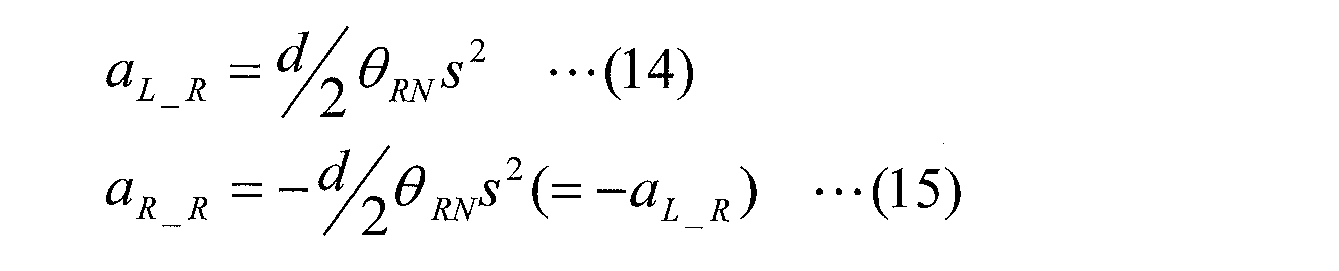
実施例の車両用アブソーバシステムが搭載されている車両には、車体重心GCとなる位置の近傍に、上記車体横加速度aYを検出するための車体横加速度センサ90が設けられており(図9参照)、当該車両用アブソーバシステムでは、そのセンサ90によって検出された車体横加速度aYと、4つの車輪10に対応して設けられた4つのばね上加速度センサ86の各々によって検出されたばね上加速度afL,afR,arL,arRとに基づいて、ロール起因成分a_R、詳しくは、左輪側ロール起因成分aL_R,右輪側ロール起因成分aR_Rが特定される。なお、実際の車両は、前輪側トレッドdfと後輪側トレッドdrとが相違していることが多く、その場合は、前輪側トレッドdfと後輪側トレッドdrとを利用して、左輪側ロール起因成分aL_R,右輪側ロール起因成分aR_Rを特定すればよい。
iv-c)ヒーブ起因成分の特定
車体がヒーブ動作を行っている場合おいて、車体に作用するヒーブ力である車体ヒーブ力FHは、下記式(16)のように示すことができる。なお、図7を参照して解るように、“mB”は、車体重量、“aZ”は、車体に作用する上下方向の加速度(車体上下加速度)である。

車体がヒーブ動作を行っている場合おいて、車体に作用するヒーブ力である車体ヒーブ力FHは、下記式(16)のように示すことができる。なお、図7を参照して解るように、“mB”は、車体重量、“aZ”は、車体に作用する上下方向の加速度(車体上下加速度)である。
一方、当該車両が有すべきヒーブ動作に関する標準的な特性を指標するものとして設定された「設定標準ヒーブ関連特性指標」の一種である設定標準ヒーブ減衰比ζHN、および、各輪のサスペンションスプリング26のばね定数kから決定されるヒーブ共振周波数ωHを用いて、車体ヒーブ力FHが作用した場合の車体のヒーブ動作を式で表せば、その式は、下記式(17)のようになる。なお、実施例のアブソーバ20は減衰係数Cが可変ではあるが、ばね上ばね下相対動作方向の推定において用いた設定標準減衰係数CNと同様に、ばね上加速度aの補正において、その補正を簡便かつ適切に行うために、設定標準ヒーブ減衰比ζHNという固定的な減衰比ζを用いている。

上記式(17)における“xHN”は、車両が設定標準ヒーブ減衰比ζHNを有することを前提とした場合の車体ヒーブ量である。
上記式(16),(17)から、設定標準ヒーブ減衰比ζHNを有する車両において車体がヒーブ動作したときの車体のヒーブ加速度(xHNs2)は、下記式(18)となる。このヒーブ加速度(xHNs2)は、ヒーブ動作に起因する各輪のばね上加速度aの成分であるヒーブ起因成分a_Hであり、下記式(18)に従うことによって、ヒーブ起因成分a_Hを特定することができる。あちなみに、このヒーブ起因成分a_Hは、どの車輪10に対応したものも互いに等しい値となる。

上記式(16),(18)における車体上下加速度aZは、4つの車輪10に対応して設けられた4つのばね上加速度センサ86の各々によって検出されたばね上加速度afL,afR,arL,arRを平均することによって取得することができ、実施例の車両用アブソーバシステムでは、それら検出された各輪のばね上加速度afL,afR,arL,arRに基づいて、ヒーブ起因成分a_Hが特定される。
iv-d)特定された各成分の除外
本実施例の車両用アブソーバシステムでは、上述のようにして特定された前輪側ピッチ起因成分af_P,後輪側ピッチ起因成分ar_P、左輪側ロール起因成分aL_R,右輪側ロール起因成分aR_R、および、ヒーブ起因成分a_Hを、ばね上加速度センサ86の各々によって検出されたばね上加速度afL,afR,arL,arRから除外することによって、それらばね上加速度afL,afR,arL,arRが補正される。具体的には、左前輪に対応するばね上加速度afLについては、下記式(19)に従って、右前輪に対応するばね上加速度afRについては、下記式(20)に従って、左後輪に対応するばね上加速度arLについては、下記式(21)に従って、右後輪に対応するばね上加速度arRについては、下記式(22)に従って、それぞれ補正される。

本実施例の車両用アブソーバシステムでは、上述のようにして特定された前輪側ピッチ起因成分af_P,後輪側ピッチ起因成分ar_P、左輪側ロール起因成分aL_R,右輪側ロール起因成分aR_R、および、ヒーブ起因成分a_Hを、ばね上加速度センサ86の各々によって検出されたばね上加速度afL,afR,arL,arRから除外することによって、それらばね上加速度afL,afR,arL,arRが補正される。具体的には、左前輪に対応するばね上加速度afLについては、下記式(19)に従って、右前輪に対応するばね上加速度afRについては、下記式(20)に従って、左後輪に対応するばね上加速度arLについては、下記式(21)に従って、右後輪に対応するばね上加速度arRについては、下記式(22)に従って、それぞれ補正される。
v)制御プログラム
本実施例の車両用アブソーバシステムにおける各車輪10に対応して設けられたアブソーバ20の制御は、コントローラ80が有するコンピュータ82が、図8にフローチャートを示すアブソーバ制御プログラムを実行することによって行われる。ちなみに、このプログラムは、短い時間ピッチ(例えば、数~数十msec)で、繰り返し実行される。以下、アブソーバ制御プログラムに沿って、アブソーバ20の制御についての処理を順次説明する。
本実施例の車両用アブソーバシステムにおける各車輪10に対応して設けられたアブソーバ20の制御は、コントローラ80が有するコンピュータ82が、図8にフローチャートを示すアブソーバ制御プログラムを実行することによって行われる。ちなみに、このプログラムは、短い時間ピッチ(例えば、数~数十msec)で、繰り返し実行される。以下、アブソーバ制御プログラムに沿って、アブソーバ20の制御についての処理を順次説明する。
アブソーバ制御プログラムに従う処理では、まず、ステップ1(以下「S1」と略す、他のステップも同様である)において、各車輪10に対応するばね上加速度a(afL,afR,arL,arR)が、各車輪10に対応して設けられたばね上加速度センサ86の検出値に基づいて取得される。続くS2において、取得されたばね上加速度aに基づいて、各車輪10に対応するばね上速度vSが演算によって求められる。具体的には、取得されたばね上加速度aに対して積分処理を行うことによって、ばね上速度vSが求められる。ばね上速度vSが正の値の場合は、ばね上動作方向が上方向であり、逆に、負の値の場合は、ばね上動作方向が下方向である。したがって、S2の処理は、ばね上動作方向推定処理と考えることができるのである。
次のS3において、ばね上加速度aのピッチ起因成分a_P,ロール起因成分a_R,ヒーブ起因成分a_Pが特定される。詳しく説明すれば、車体前後加速度センサ88によって検出された車体前後加速度aXと、先に取得されているばね上加速度a(afL,afR,arL,arR)とに基づいて、上記式(6)~(10)に従って、前輪側ピッチ起因成分af_P,後輪側ピッチ起因成分ar_Pが特定され、また、車体横加速度センサ90によって検出された車体横加速度aYと、先に取得されているばね上加速度a(afL,afR,arL,arR)とに基づいて、上記式(11)~(15)に従って、左輪側ロール起因成分aL_R,右輪側ロール起因成分ar_Pが特定され、さらに、先に取得されているばね上加速度a(afL,afR,arL,arR)に基づいて、上記式(16)~(18)に従って、ビーブ起因成分a_Pが特定される。そして、S4において、特定された3つの成分を除外する処理が、上記式(19)~(22)のいずれかに従って行われ、各車輪10に対応したばね上加速度a(afL,afR,arL,arR)が、補正される。
続くS5では、各車輪10に対応した補正後のばね上加速度aに対して微分処理を行うことで、各車輪10に対応したばね上加加速度a′が演算によって求められる。そして、S6において、求められたばね上加加速度a′に基づいて、上記式(3)に従って、ばね上ばね下相対動作方向指標としてのばね上ばね下相対速度vS/USが、各車輪10について演算される。演算されたばね上ばね下相対速度vS/USが正の値となる場合には、ばね上ばね下動作方向は接近方向であり、バウンド動作が行われていると推定することができ、負の値となる場合は、ばね上ばね下動作方向は離間方向であり、リバウンド動作がおこなわれていると推定することができる。したがって、S5,S6の処理は、ばね上ばね下相対動作方向を推定する処理と考えることができるのである。
次のS7において、各車輪10に対応したばね上速度vSとばね上ばね下相対速度vS/USとの積の値が正であるか負であるかが判断される。その積の値が正であると判断された場合は、ばね上動作方向が上方向でありかつばね上ばね下相対動作方向が接近方向である状態、若しくは、ばね上動作方向が下方向でありかつばね上ばね下相対動作方向が離間方向である状態となっており、S8において、アブソーバ力作用状態が、推進力作用状態であると認定される。逆に、その積の値が負であると判断された場合は、すなわち、正でないとと判断された場合は、ばね上動作方向が下方向でありかつばね上ばね下相対動作方向が接近方向である状態、若しくは、ばね上動作方向が上方向でありかつばね上ばね下相対動作方向が離間方向である状態となっており、S9において、アブソーバ力作用状態が、抵抗力作用状態であると認定される。つまり、S7~S9の処理は、アブソーバ力作用状態を判断するための処理と考えることができるのである。
ある車輪10についてのアブソーバ力作用状態が推進力作用状態であると認定された場合には、S10において、その車輪10に対応するアブソーバ20の目標減衰係数C*が、設定範囲における最小の減衰係数Cである最小減衰係数CMINに決定される。一方、ある車輪10についてのアブソーバ力作用状態が抵抗力作用状態であると認定された場合には、S11において、その車輪10に対応するアブソーバ20の目標減衰係数C*が、設定範囲において、その車輪10に対応するばね上速度vSが大きければ大きい程大きな値に決定される。つまり、S10,S11の処理は、目標減衰係数C*を目標アブソーバ力指標として決定する処理と考えることができる。なお、フローチャートでは省略されているが、S7~S11の処理は、車輪10ごとに行われる。
そして、S12において、各車輪10に対応して配設されたアブソーバ20への供給電流Iの目標である目標供給電流I*が、車輪10ごとに決定され、S13において、車輪10ごとに決定された目標供給電流I* についての信号が、各アブソーバ20の可変弁28に対応するドライバ84に送信される。その信号の送信の後、本プログラムの1回の実行が終了する。各ドライバ84は、各アブソーバ20のアブソーバ力変更機構として機能する可変弁28に供給される電流Iが、目標供給電流I*となるように作動し、その作動の下、各アブソーバ20は、ばね上制振制御において好適な減衰力を発生させることになる。したがって、S12,S13の処理は、アブソーバ力変更機構を制御するための処理と考えることができる。
vi)コントローラの機能構成
以下に、図9の機能ブロック図を参照しつつ、コントローラ80の機能構成について説明する。先に説明したように、コントローラ80は、コンピュータ82と、各アブソーバ20の可変弁28に対応した4つのドライバ84とを含んで構成されており、コンピュータ82は、各車輪10に対応した4つのばね上加速度センサ86,車体前後加速度センサ88,車体横加速度センサ90と、それらからの検出信号を受信可能に接続されている。また、各ドライバ84は、バッテリ78に、それからの電流を受けるべく接続されるとともに、対応するアブソーバ20の可変弁28に、それへ電流を供給すべく接続されている。
以下に、図9の機能ブロック図を参照しつつ、コントローラ80の機能構成について説明する。先に説明したように、コントローラ80は、コンピュータ82と、各アブソーバ20の可変弁28に対応した4つのドライバ84とを含んで構成されており、コンピュータ82は、各車輪10に対応した4つのばね上加速度センサ86,車体前後加速度センサ88,車体横加速度センサ90と、それらからの検出信号を受信可能に接続されている。また、各ドライバ84は、バッテリ78に、それからの電流を受けるべく接続されるとともに、対応するアブソーバ20の可変弁28に、それへ電流を供給すべく接続されている。
コンピュータ82は、それぞれがアブソーバ制御プログラム(以下、単に「制御プログラム」と言う場合がある)の実行によって機能する若しくは実現されるいくつかの機能部を有している。具体的には、ばね上加速度補正部100,相対動作方向推定部102,ばね上速度演算部104,アブソーバ力作用状態判断部106,目標アブソーバ力指標決定部108,目標供給電流決定部110を有している。
ばね上加速度補正部100は、それぞれが下位の機能部であるピッチ起因成分特定部112,ロール起因成分特定部114,ヒーブ起因成分特定部116と、成分除外処理部118とを含んで構成されている。ピッチ起因成分特定部112は、ばね上加速度aのピッチ起因成分a_P、詳しくは、前輪側ピッチ起因成分af_Pおよび後輪側ピッチ起因成分ar_Pを特定する機能を、ロール起因成分特定部114は、ばね上加速度aのロール起因成分a_R、詳しくは、左輪側ロール起因成分aL_Rおよび右輪側ピッチ起因成分aR_Rを特定する機能を、ロール起因成分特定部116は、ばね上加速度aのヒーブ起因成分a_Hを特定する機能を、それぞれ有している。それら3つの特定部112,114,116は、制御プログラムのS3の処理によって実現される機能部である。成分除外処理部118は、それら3つの特定部112,114,116によって特定された上記3種の成分を、ばね上加速度センサ86の検出値に基づいて取得されたばね上加速度aから除外する処理を行う機能を有しており、制御プログラムのS4の処理によって実現される機能部である。
相対動作方向推定部102は、それぞれが下位の機能部であるばね上加加速度演算部120,ばね上ばね下相対速度演算部122を含んで構成されている。ばね上加加速度演算部120は、補正されたばね上加速度aに微分処理を行ってばね上加加速度a′を取得する機能を有し、制御プログラムのS5の処理によって実現される機能部である。ばね上ばね下相対速度演算部122は、取得されたばね上加加速度a′に基づいて、各車輪10に対応するばね上ばね下相対速度vS/USを求める機能を有し、制御プログラムのS6の処理によって実現される機能部である。求められたばね上ばね下相対速度vS/USは、それの値の正負によって、ばね上ばね下相対動作方向が接近方向であるか離間方向であるかを推定できることから、ばね上ばね下相対速度vS/USを求めることは、ばね上ばね下相対動作方向を推定することと考えることができる。そのため、ばね上加加速度演算部120,ばね上ばね下相対速度演算部122を含んで構成される機能部を、「相対動作方向推定部」と名付けている。なお、先に説明したように、ばね上加加速度a′に基づくばね上ばね下相対速度vS/USの演算は、フィルタによる処理、詳しくは、1次ローパスフィルタによる処理と等価であることから、ばね上ばね下相対速度演算部122は、フィルタとして機能する部分と考えることができる。
ばね上速度演算部104は、ばね上加速度センサ86の検出によって取得されたばね上加速度aを積分処理することで、各車輪10に対応したばね上速度vSを求める機能を有し、制御プログラムのS2の処理によって実現される機能部である。求められたばね上速度vSは、それの値の正負によって、ばね上動作方向が上方向であるか下方向であるかを推定できることから、ばね上速度vSを求めることは、ばね上動作方向を推定することと考えることができる。
アブソーバ力作用状態判断部106は、相対動作推定部102によって推定されたばね上ばね下動作方向と、ばね上速度演算部104が演算によって求めたばね上動作速度vSから推定されるばね上動作方向とに基づいて、アブソーバ力作用状態が抵抗力作用状態であるか推進力作用状態であるかを判断する機能を有している。具体的には、ばね上ばね下相対速度vS/USとばね上速度ばね上速度vSとの積の正負(図では、“SIGN(vS/US・vS)”と表わされている)が出力される。アブソーバ力作用状態判断部106は、制御プログラムのS7~S9の処理によって実現される機能部である。
目標アブソーバ力指標決定部108は、ばね上速度vSとアブソーバ力作用状態とに基づいて、各車輪10に対応する目標アブソーバ力指標としての目標減衰係数C*を決定する機能を有する。簡単に言えば、目標アブソーバ力指標決定部108は、目標減衰係数C*を、推進力作用状態となる場合には最小減衰係数CMINに決定し、抵抗力作用状態となる場合には、ばね上速度vSに応じた値に決定する。目標アブソーバ力指標決定部108は、制御プログラムのS10,S11の処理によって実現される機能部である。
目標供給電流決定部110は、決定された目標減衰係数C*に基づいて、各車輪10に対応するアブソーバ20の可変弁28へ供給される電流の目標値として、目標供給電流I*を決定する機能を有し、制御プログラムのS12の処理によって実現される機能部である。目標供給電流I*についての信号が各ドライバ84に送られ、各ドライバ84は、自身に対応するアブソーバ20の可変弁28に、その信号に応じた大きさの電流を供給する。したがって、目標供給電流決定部110とドライバ84とを含んで、目標減衰係数C*に基づいてアブソーバ力変更機構である可変弁28を制御するアブソーバ力変更機構制御部124が構成されていると考えることができる。
なお、目標アブソーバ力指標を、目標供給電流I*と考えることもできる。そのように考えた場合は、上記目標供給電流決定部110をも含んで、上記目標アブソーバ力指標決定部108が構成されることになり、また、アブソーバ力変更機構制御部124が、ドライバ84のみによって構成されることになる。
以下に、請求可能発明に係る車両用アブソーバシステムのいくつかの変形例について説明する。
上記液圧式アブソーバ20は、ダブルウィッシュボーン型のサスペンション装置に採用されていたが、請求可能発明に係る車両用アブソーバシステムは、アブソーバが、他の型式のサスペンション装置に採用されるものであってもよい。例えば、アブソーバが、ストラットマウント型(マクファーソン型),マルチリンク型,トレーリングアーム型等、種々の型式のサスペンション装置に採用されてもよいのである。
上記電磁式可変弁28は、アブソーバ力変更機構の一例であり、先に説明したように、ポペット弁を主要構成要素として構成されたものであるが、アブソーバは、他の種類のアブソーバ力変更機構、例えば、減衰力を変更する原理において可変弁28とは異なる種類のアブソーバ力変更機構を備えていてもよい。例えば、作動液の流れる流路の断面積を変更することで、作動液の流れに与える抵抗を変更して減衰力を変更するような構成のアブソーバ力変更機構であってもよい。
上記アブソーバ20の制御において、ばね上ばね下相対動作方向の推定の際に基づくばね上加速度aは、ピッチ起因成分a_P,ロール起因成分a_R,ヒーブ起因成分a_Hの3種の成分を除外することによって、補正が行われている。そのように3種の成分を除外するのではなく、ピッチ起因成分a_P,ロール起因成分a_R,ヒーブ起因成分a_Hのうちのいずれか1種またはいずれか2種のみを除外することによって、ばね上加速度aを補正してもよい。また、請求可能発明に係る車両用アブソーバシステムは、ばね上加速度aを補正せずしてばね上ばね下相対動作方向を推定する態様のシステムを排除するものではない。
上記コントローラ80は、コンピュータ82を主要構成要素とし、そのコンピュータ82がプログラムを実行することによって、アブソーバ20の制御を行うように構成されていたが、請求可能発明に係る車両用アブソーバシステムにおけるコントローラは、アナログ若しくはデジタルの処理を実行する専用の論理回路を主要構成要素とし、プログラムの実行を行わずしてアブソーバ20の制御を行うように構成されたものであってもよい。また、いわゆるシーケンサのようなものであってもよい。
10:車輪〔ばね下部〕 20:液圧式ショックアブソーバ 22:マウント部〔ばね上部〕 26:サスペンションスプリング 28:電磁式可変弁〔アブソーバ力変更機構〕 80:コントローラ 86:ばね上加速度センサ 88:車体前後加速度センサ 90:車体横加速度センサ 100:ばね上加速度補正部 102:相対動作方向推定部 104:ばね上速度演算部 106:アブソーバ力作用状態判断部 108:目標アブソーバ力指標決定部 110:目標供給電流決定部 112:ピッチ起因成分決定部 114:ロール起因成分決定部 116:ヒーブ起因成分決定部 118:成分除外処理部 120:ばね上加加速度演算部 122:ばね上ばね下相対速度演算部〔1次ローパスフィルタ〕 124:アブソーバ力変更機構制御部 vS:ばね上速度 vS/US:ばね上ばね下相対速度 a:ばね上加速度 a_P:ピッチ起因成分 a_R:ロール起因成分 a_H:ヒーブ起因成分 a′:ばね上加加速度 aX:車体前後加速度 aY:車体横加速度 C*:目標減衰係数 I*:目標供給電流
Claims (8)
- 車両のばね上部とばね下部とを繋ぐように配設され、自身が発生させる力であるアブソーバ力をばね上部とばね下部との相対動作に対する減衰力として作用させるとともに、そのアブソーバ力を変更するためのアブソーバ力変更機構を有する液圧式ショックアブソーバと、
前記液圧式ショックアブソーバを制御するコントローラと
を備えた車両用アブソーバシステムであって、
前記コントローラが、
ばね上部の上下方向の加速度であるばね上加速度に基づいて、ばね上部とばね下部との相対動作の方向であるばね上ばね下相対動作方向が、ばね上部とばね下部とが互いに離間する方向である離間方向であるか、互いに接近する方向である接近方向であるかを推定する相対動作方向推定部を有し、前記推定されたばね上ばね下相対動作方向に基づいて、前記アブソーバ力変更機構を制御するように構成された車両用アブソーバシステム。 - 前記相対動作方向推定部が、ばね上加速度に基づいて、ばね上部の加加速度であるばね上加加速度を取得し、その取得されたばね上加加速度に基づいて、ばね上ばね下相対動作方向が離間方向であるか接近方向であるかを推定するように構成された請求項1に記載の車両用アブソーバシステム。
- 前記相対動作方向推定部が、ばね上加加速度が入力されることによってばね上部とばね下部との相対動作の速度であるばね上ばね下相対速度が出力されるフィルタとして機能する部分を有し、その出力されたばね上ばね下相対動作速度に基づいて、ばね上ばね下相対動作方向が離間方向であるか接近方向であるかを推定するように構成された請求項2に記載の車両用アブソーバシステム。
- 前記相対動作方向推定部が、前記液圧式ショックブソーバが発揮すべき標準的な減衰力特性を指標するものとして設定された設定標準特性指標を利用して、ばね上ばね下相対動作方向が離間方向であるか接近方向であるかを推定するように構成された請求項1ないし請求項3のいずれか1つに記載の車両用アブソーバシステム。
- 前記コントローラが、
それぞれがばね上加速度の一成分であるところの (a)車体のピッチ動作に起因する成分であるピッチ起因成分, (b)車体のロール動作に起因する成分であるロール起因成分, (c)車体のヒーブ動作に起因する成分であるヒーブ起因成分の少なくとも1つを除外するようにして、ばね上加速度を補正するばね上加速度補正部を有し、
前記相対動作方向推定部が、前記補正されたばね上加速度に基づいて、ばね上ばね下動作方向が離間方向であるか接近方向であるかを推定するように構成された請求項1ないし請求項4のいずれか1つに記載の車両用アブソーバシステム。 - 前記コントローラが、
前記推定されたばね上ばね下相対動作方向と、ばね上部の動作の方向であるばね上動作方向とに基づいて、ばね上部に対してアブソーバ力が作用する状態であるアブソーバ力作用状態が、アブソーバ力がばね上部の動作の抵抗となる方向に作用する抵抗力作用状態であるか、ばね上部の動作を推進する方向に作用する推進力作用状態であるかを判断するアブソーバ力作用状態判断部と、
ばね上部の動作を減衰させるべく、前記判断されたアブソーバ力作用状態に基づいて、発生させるべきアブソーバ力を指標する目標アブソーバ力指標を決定する目標アブソーバ力指標決定部と、
前記決定された目標アブソーバ力指標に基づいて、前記アブソーバ力変更機構を制御するアブソーバ力変更機構制御部と
を有する請求項1ないし請求項5のいずれか1つに記載の車両用アブソーバシステム。 - 前記目標アブソーバ力指標決定部が、前記判断されたアブソーバ力作用状態が推進力作用状態である場合に、通常におけるアブソーバ力の範囲として設定された設定範囲内においてアブソーバ力を最も小さくすべく、目標アブソーバ力指標を決定するように構成された請求項6に記載の車両用アブソーバシステム。
- 前記目標アブソーバ力指標決定部が、前記判断されたアブソーバ力作用状態が抵抗力作用状態である場合に、ばね上部の動作の速度であるばね上速度が大きい程前記設定範囲内においてアブソーバ力を大きくすべく、目標アブソーバ力指標を決定するように構成された請求項6または請求項7に記載の車両用アブソーバシステム。
Priority Applications (1)
| Application Number | Priority Date | Filing Date | Title |
|---|---|---|---|
| PCT/JP2013/064652 WO2014192065A1 (ja) | 2013-05-27 | 2013-05-27 | 車両用アブソーバシステム |
Applications Claiming Priority (1)
| Application Number | Priority Date | Filing Date | Title |
|---|---|---|---|
| PCT/JP2013/064652 WO2014192065A1 (ja) | 2013-05-27 | 2013-05-27 | 車両用アブソーバシステム |
Publications (1)
| Publication Number | Publication Date |
|---|---|
| WO2014192065A1 true WO2014192065A1 (ja) | 2014-12-04 |
Family
ID=51988142
Family Applications (1)
| Application Number | Title | Priority Date | Filing Date |
|---|---|---|---|
| PCT/JP2013/064652 WO2014192065A1 (ja) | 2013-05-27 | 2013-05-27 | 車両用アブソーバシステム |
Country Status (1)
| Country | Link |
|---|---|
| WO (1) | WO2014192065A1 (ja) |
Citations (5)
| Publication number | Priority date | Publication date | Assignee | Title |
|---|---|---|---|---|
| JPH06344746A (ja) * | 1993-06-14 | 1994-12-20 | Aisin Seiki Co Ltd | サスペンションのスカイフック制御装置 |
| JPH0920120A (ja) * | 1995-07-04 | 1997-01-21 | Unisia Jecs Corp | 車両懸架装置 |
| JPH0920121A (ja) * | 1995-07-06 | 1997-01-21 | Unisia Jecs Corp | 車両懸架装置 |
| JPH10912A (ja) * | 1996-06-13 | 1998-01-06 | Toyota Motor Corp | 車両用サスペンション装置の減衰力制御装置 |
| JP2006264367A (ja) * | 2005-03-22 | 2006-10-05 | Kayaba Ind Co Ltd | 緩衝器の制御装置 |
-
2013
- 2013-05-27 WO PCT/JP2013/064652 patent/WO2014192065A1/ja active Application Filing
Patent Citations (5)
| Publication number | Priority date | Publication date | Assignee | Title |
|---|---|---|---|---|
| JPH06344746A (ja) * | 1993-06-14 | 1994-12-20 | Aisin Seiki Co Ltd | サスペンションのスカイフック制御装置 |
| JPH0920120A (ja) * | 1995-07-04 | 1997-01-21 | Unisia Jecs Corp | 車両懸架装置 |
| JPH0920121A (ja) * | 1995-07-06 | 1997-01-21 | Unisia Jecs Corp | 車両懸架装置 |
| JPH10912A (ja) * | 1996-06-13 | 1998-01-06 | Toyota Motor Corp | 車両用サスペンション装置の減衰力制御装置 |
| JP2006264367A (ja) * | 2005-03-22 | 2006-10-05 | Kayaba Ind Co Ltd | 緩衝器の制御装置 |
Similar Documents
| Publication | Publication Date | Title |
|---|---|---|
| JP5733426B2 (ja) | 車両 | |
| JP6052405B2 (ja) | 車両用サスペンションシステム | |
| JP5934470B2 (ja) | サスペンション装置 | |
| EP2022655B1 (en) | Control apparatus of a variable damping force damper | |
| US20230111977A1 (en) | Kinetic Suspension System With Roll And Pitch Stiffness Deactivation Based On Road Profile Information | |
| US11904841B2 (en) | Suspension system integration with advanced driver assistance system | |
| US8311704B2 (en) | Control apparatus of variable damping force damper | |
| EP2537691B1 (en) | Damping force control device for vehicle | |
| JP2009508751A (ja) | サスペンション制御装置、同装置を具備する車両、実現方法およびプログラム | |
| WO2015163426A1 (ja) | ダンパ制御装置 | |
| US11529837B2 (en) | Damper control | |
| JP2020117196A (ja) | 車両運動状態推定装置 | |
| JP4382829B2 (ja) | ばね上速度推定装置 | |
| JP2019025989A (ja) | サスペンション制御システム | |
| JP2015217885A (ja) | 車両用アブソーバシステム | |
| WO2014192065A1 (ja) | 車両用アブソーバシステム | |
| JP5808615B2 (ja) | サスペンション制御装置 | |
| CN109203904B (zh) | 用于车辆的行驶控制系统 | |
| JP5664569B2 (ja) | 車両用サスペンションシステム | |
| JP5157683B2 (ja) | サスペンション制御装置 | |
| JP2019031125A (ja) | サスペンション制御システム | |
| JP2009137342A (ja) | 減衰力可変ダンパの制御装置 | |
| JP5104594B2 (ja) | 車両制御装置 | |
| JP2003326933A (ja) | ショックアブソーバの減衰力制御装置及び変動量推定装置 | |
| JP7369879B2 (ja) | スリップ状態検出装置およびサスペンション制御装置 |
Legal Events
| Date | Code | Title | Description |
|---|---|---|---|
| 121 | Ep: the epo has been informed by wipo that ep was designated in this application |
Ref document number: 13885576 Country of ref document: EP Kind code of ref document: A1 |
|
| NENP | Non-entry into the national phase |
Ref country code: DE |
|
| 122 | Ep: pct application non-entry in european phase |
Ref document number: 13885576 Country of ref document: EP Kind code of ref document: A1 |
|
| NENP | Non-entry into the national phase |
Ref country code: JP |