WO2014184961A1 - 太陽熱発電用集熱体 - Google Patents
太陽熱発電用集熱体 Download PDFInfo
- Publication number
- WO2014184961A1 WO2014184961A1 PCT/JP2013/063846 JP2013063846W WO2014184961A1 WO 2014184961 A1 WO2014184961 A1 WO 2014184961A1 JP 2013063846 W JP2013063846 W JP 2013063846W WO 2014184961 A1 WO2014184961 A1 WO 2014184961A1
- Authority
- WO
- WIPO (PCT)
- Prior art keywords
- glass layer
- metal component
- substrate
- silicon carbide
- collector
- Prior art date
Links
Images


Classifications
-
- F—MECHANICAL ENGINEERING; LIGHTING; HEATING; WEAPONS; BLASTING
- F24—HEATING; RANGES; VENTILATING
- F24S—SOLAR HEAT COLLECTORS; SOLAR HEAT SYSTEMS
- F24S80/00—Details, accessories or component parts of solar heat collectors not provided for in groups F24S10/00-F24S70/00
- F24S80/10—Materials for heat-exchange conduits
-
- F—MECHANICAL ENGINEERING; LIGHTING; HEATING; WEAPONS; BLASTING
- F24—HEATING; RANGES; VENTILATING
- F24S—SOLAR HEAT COLLECTORS; SOLAR HEAT SYSTEMS
- F24S20/00—Solar heat collectors specially adapted for particular uses or environments
- F24S20/20—Solar heat collectors for receiving concentrated solar energy, e.g. receivers for solar power plants
-
- F—MECHANICAL ENGINEERING; LIGHTING; HEATING; WEAPONS; BLASTING
- F24—HEATING; RANGES; VENTILATING
- F24S—SOLAR HEAT COLLECTORS; SOLAR HEAT SYSTEMS
- F24S70/00—Details of absorbing elements
- F24S70/10—Details of absorbing elements characterised by the absorbing material
- F24S70/16—Details of absorbing elements characterised by the absorbing material made of ceramic; made of concrete; made of natural stone
-
- F—MECHANICAL ENGINEERING; LIGHTING; HEATING; WEAPONS; BLASTING
- F24—HEATING; RANGES; VENTILATING
- F24S—SOLAR HEAT COLLECTORS; SOLAR HEAT SYSTEMS
- F24S70/00—Details of absorbing elements
- F24S70/30—Auxiliary coatings, e.g. anti-reflective coatings
-
- F—MECHANICAL ENGINEERING; LIGHTING; HEATING; WEAPONS; BLASTING
- F24—HEATING; RANGES; VENTILATING
- F24S—SOLAR HEAT COLLECTORS; SOLAR HEAT SYSTEMS
- F24S70/00—Details of absorbing elements
- F24S70/60—Details of absorbing elements characterised by the structure or construction
-
- F—MECHANICAL ENGINEERING; LIGHTING; HEATING; WEAPONS; BLASTING
- F24—HEATING; RANGES; VENTILATING
- F24S—SOLAR HEAT COLLECTORS; SOLAR HEAT SYSTEMS
- F24S80/00—Details, accessories or component parts of solar heat collectors not provided for in groups F24S10/00-F24S70/00
- F24S2080/01—Selection of particular materials
- F24S2080/011—Ceramics
-
- Y—GENERAL TAGGING OF NEW TECHNOLOGICAL DEVELOPMENTS; GENERAL TAGGING OF CROSS-SECTIONAL TECHNOLOGIES SPANNING OVER SEVERAL SECTIONS OF THE IPC; TECHNICAL SUBJECTS COVERED BY FORMER USPC CROSS-REFERENCE ART COLLECTIONS [XRACs] AND DIGESTS
- Y02—TECHNOLOGIES OR APPLICATIONS FOR MITIGATION OR ADAPTATION AGAINST CLIMATE CHANGE
- Y02E—REDUCTION OF GREENHOUSE GAS [GHG] EMISSIONS, RELATED TO ENERGY GENERATION, TRANSMISSION OR DISTRIBUTION
- Y02E10/00—Energy generation through renewable energy sources
- Y02E10/40—Solar thermal energy, e.g. solar towers
- Y02E10/44—Heat exchange systems
Definitions
- the present invention relates to a solar power collector.
- Solar power generation uses a mirror or lens to concentrate sunlight on a heat collector, heat the heat medium in the heat collector, and rotate the turbine with steam generated by heat exchange with the heated heat medium.
- This is a technology for generating electricity.
- silicon carbide ceramics as a heat collector for solar thermal power generation is proposed (for example, refer to patent documents 1).
- Ceramic heat collectors have the advantage of superior heat resistance compared to metal heat collectors.
- silicon carbide ceramics have a high thermal conductivity and a low coefficient of thermal expansion, they are excellent in thermal shock resistance and are suitable as a heat collector that becomes extremely hot when sunlight is collected.
- silicon carbide has a problem that it is oxidized when heated to a high temperature in the presence of oxygen. It is said that if the surface of silicon carbide is coated with a silicon dioxide film produced by the oxidation of silicon carbide, further oxidation will be suppressed to some extent, but that is not enough to suppress oxidation. Is the actual situation.
- an object of the present invention is to provide a heat collector for solar power generation in which oxidation is suppressed while using a silicon carbide ceramic sintered body as a base.
- a solar power generation heat collector (hereinafter sometimes simply referred to as “heat collector”) according to the present invention is “a silicon carbide having a flow path through which a heat medium flows.
- a second glass layer of silicate glass having a smaller sum of the content of alkali metal component and alkaline earth metal component covering the layer than the first glass layer.
- “Substrate on which a plurality of channels for circulating a heat medium are formed” includes a honeycomb structure described later, a block-shaped structure having a through-hole, a tubular structure, and a plurality of tubes Can be exemplified by a structure in which the major axis directions are aligned.
- the “first glass layer of silicate glass” is a coating agent containing alkali metal components such as sodium oxide, potassium oxide and potassium carbonate, and alkaline earth metal components such as calcium oxide and calcium carbonate in addition to silicon dioxide , Referred to as “first coating agent”), and the surface of the substrate is coated and then heated to vitrify.
- the first glass layer may contain only one of the alkali metal component and the alkaline earth metal component or may contain both.
- the “first glass layer” can contain silicon (a simple substance), boron oxide, aluminum oxide and the like in addition to silicon dioxide, an alkali metal component and / or an alkaline earth metal component.
- the coefficient of thermal expansion of the silicate glass can be adjusted by the content of boron oxide.
- the strength of the silicate glass can be adjusted by the content of aluminum oxide.
- the “second glass layer” and the original coating agent can contain the same components as the first glass layer and the first coating agent. However, the sum of the content rates of the alkali metal component and the alkaline earth metal component in the second glass layer is smaller than that of the first glass layer.
- the “surface of the substrate” covered with the first glass layer includes the inner peripheral surface of the flow path through which the heat medium flows.
- the heat collector When the sunlight is concentrated on the heat collector, the heat collector becomes hot.
- the base of the heat collector is a silicon carbide ceramic sintered body, and the silicon carbide is oxidized by being heated to a high temperature in the presence of oxygen.
- the surface of the substrate is covered with the first glass layer and the second glass layer of silicate glass. Therefore, the contact between silicon carbide and oxygen is prevented by the silicate glass layer, and the oxidation of silicon carbide is effectively suppressed.
- alkali metal components and alkaline earth metal components melt or soften silicon dioxide under heating. Therefore, when the surface of the substrate is coated with the original first coating agent to form the first glass layer and heated, the first coating agent melts and softens. Thereby, since the first coating agent adheres well to the surface of the substrate, the first glass layer after vitrification firmly adheres to the substrate which is a different material. When the substrate is porous, the first coating agent melted and softened sufficiently enters the open pores, and the substrate is densified by solidification. Thereby, the heat capacity of the substrate is increased, and the efficiency of heat exchange with the heat medium is increased.
- the first glass layer containing an alkali metal component and / or an alkaline earth metal component is melted and softened even in a high temperature environment when the heat collector is used for solar thermal power generation. Therefore, if the outermost layer in the heat collector is the first glass layer, the heat collector adheres to the casing that houses the heat collector or a plurality of pieces are accommodated in the casing by melting and softening the first glass layer. There is a possibility that the collected heat collectors adhere to each other.
- the 2nd glass layer is coat
- This second glass layer is less likely to soften and melt even at high temperatures because the sum of the content ratios of the alkali metal component and alkaline earth metal component is smaller than that of the first glass layer. Thereby, the adhesion between the heat collector and the casing and the adhesion between the heat collectors housed in the casing are suppressed. Therefore, when the heat collecting body deteriorates or breaks with use, the work of removing the heat collecting body from the casing or the work of exchanging only some of the heat collecting bodies among the plurality of heat collecting bodies is easy.
- the second coating agent that is the source of the second glass layer does not soften or melt as much as the first coating agent when heat-treated after coating.
- the second glass layer is a layer of silicate glass similar to the first glass layer. Therefore, unlike the case of coating a heterogeneous material, the second glass layer is firmly fixed to the first glass layer even if it is not softened or melted by heating.
- a silicate glass containing an alkali metal component and / or an alkaline earth metal component softens and extends at a high temperature and plastically deforms. Therefore, even if a crack is generated in a ceramic substrate, which is a brittle material, the first glass layer covering the surface of the substrate softens and fills the crack, so the crack extends and breaks. To be suppressed. Therefore, the heat collector of the present invention is excellent in thermal shock resistance by being provided with the first glass layer in addition to being composed of silicon carbide ceramics having high thermal shock resistance. High mechanical strength.
- the solar power collector according to the present invention has the above-described configuration, wherein “the sum of the content ratios of the alkali metal component and the alkaline earth metal component in the second glass layer is 3.6% by mass or less in terms of oxide. Can be. "
- the solar power collector according to the present invention includes “a plurality of the substrates are bonded via a bonding layer to form a substrate unit, and the first glass layer covers the surface of the substrate unit. It can be “coated”.
- the entire heat collector can be enlarged regardless of the size of each substrate. Thereby, the quantity of the heat medium heat-exchanged with a heat collecting body can be increased, and solar thermal power generation can be performed efficiently.
- the first glass layer covering the surface of the base unit is covered with the second glass layer. Therefore, when the heat collector is used in a high temperature environment, the adhesion between the base unit and the casing and the adhesion between the base units are suppressed by the presence of the second glass layer. Thereby, when the heat collecting body deteriorates or breaks with use, the base unit can be replaced as a unit.
- the solar power collector according to the present invention has a honeycomb structure including a plurality of cells partitioned by partition walls extending in a single direction, in addition to the above-described structure, The cell may constitute the flow path ”.
- Honeycomb structure has a large specific surface area. Therefore, the heat collector of this configuration has an advantage that the efficiency of heat exchange with the heat medium is high.
- a ceramic honeycomb structure is generally formed by extrusion molding, and it is difficult to produce a large molded body by extrusion molding.
- the heat collection body is configured by the base unit in which a plurality of base bodies are joined, even if the base body is a honeycomb structure, the entire heat collection body can be enlarged.
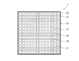
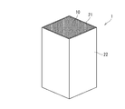
- FIG. 1st embodiment of this invention It is a cross-sectional view of the heat collection body of 1st embodiment of this invention. It is sectional drawing of the partition in the heat collecting body of FIG. It is a perspective view of the heat collecting body of FIG. It is the example which accommodated the some of the heat collecting body of FIG. 1 in the casing. It is the other example which accommodated the some of the heat collecting body of FIG. 1 in the casing. It is a cross-sectional view of the heat collection body of 2nd embodiment of this invention. 7 is an example in which a plurality of the heat collectors of FIG. 6 are accommodated in a casing. It is a graph which shows the mass increase accompanying the increase in a heating time about an Example and a comparative example by the ratio of the change with respect to initial mass.
- the heat collecting body 1 which is 1st embodiment of this invention is demonstrated using FIG. 1 thru
- the heat collector 1 of the first embodiment includes a base 10 of a silicon carbide based ceramic sintered body in which a flow path for circulating a heat medium is formed, and an alkali metal covering at least a part of the surface of the base 10
- the first glass layer 21 of the silicate glass containing the component and / or the alkaline earth metal component, and the sum of the contents of the alkali metal component and the alkaline earth metal component covering the first glass layer 21 is the first.
- the second glass layer 22 of silicate glass smaller than the one glass layer 21 is provided.
- the base 10 of the heat collector 1 has a honeycomb structure including a plurality of cells 15 that are partitioned by partition walls 11 extending in a single direction. Constitutes the road.
- Such a heat collector 1 can be manufactured by the following manufacturing method. That is, the manufacturing method of the heat collecting body 1 of 1st embodiment is the raw material which becomes a silicon carbide ceramic sintered body by baking, and is divided into the plurality of partition walls 11 that extend in a single axial direction and are arranged in a row.
- the surface of the substrate 10 is coated with a first coating agent containing silicon dioxide, an alkali metal component and / or an alkaline earth metal component, and the substrate 10 coated with the first coating agent is heated to convert the first coating agent to silicic acid.
- a first glass layer forming step for fixing to the surface of the substrate 10 as the first glass layer 21 of the system glass, and silicon dioxide containing content of alkali metal component and alkaline earth metal component is a predetermined value
- the surface of the first glass layer 21 is coated with the lower second coating agent, the substrate 10 coated with the second coating agent is heated, and the second coating agent is used to adjust the content of the alkali metal component and the alkaline earth metal component.
- the raw material that becomes a silicon carbide ceramic sintered body by firing is mixed with water together with additives such as a binder and a surfactant to form a kneaded product, and this is extruded.
- additives such as a binder and a surfactant to form a kneaded product
- a formed article having a honeycomb structure is obtained.
- a raw material containing silicon carbide powder can be used as the ceramic raw material that becomes a silicon carbide ceramic sintered body by firing.
- a raw material containing a silicon source and a carbon source that generate silicon carbide by heating can be used, and silicon carbide can be sintered while reacting (reaction sintering).
- a mixed raw material of silicon carbide powder as an aggregate and a silicon source and a carbon source that generate silicon carbide can be used as a raw material.
- the silicon carbide powder as the aggregate is preferably 65% by mass to 95% by mass with respect to the mixed raw material.
- the ratio of the silicon carbide powder as the aggregate is smaller than 65% by mass, the strength of the obtained sintered body tends to be low.
- it is more than 95% by mass it may be difficult to sinter. Note that it is more desirable that the ratio of the silicon carbide powder as the aggregate to the mixed raw material is 75% by mass to 85% by mass because the above-described contradictory actions can be balanced.
- Si / C silicon carbide is generated in a stoichiometric amount, but Si / C is reduced to 0. .5 to 1.5 is desirable.
- Si / C is smaller than 0.5, the remaining carbon content is too much, which may cause rough atmospheric pores, and may inhibit the growth of the generated silicon carbide particles.
- Si / C is larger than 1.5, the amount of silicon carbide produced is small, and reactive sintering tends to be insufficient. If Si / C is 0.8 to 1.2, the excess or deficiency of silicon and carbon is small and more desirable.
- silicon nitride and silicon can be used as the silicon source
- examples of the carbon source include graphite, coal, coke, and charcoal. You may perform the drying process which dries the obtained molded object after a formation process and before a baking process.
- the heating furnace is kept in a non-oxidizing atmosphere at a temperature of 1800 ° C. to 2300 ° C. for a certain time. If the firing temperature is lower than 1800 ° C, reactive sintering may be insufficient, and if it exceeds 2350 ° C, silicon carbide may sublime.
- a firing temperature of 2000 ° C. to 2200 ° C. is more desirable because a sintered body with sufficient strength can be obtained in a relatively short time.
- the sintering time depends on the size of the molded body, but can be, for example, 30 minutes to 3 hours.
- the non-oxidizing atmosphere can be an inert gas atmosphere such as argon or helium, a nitrogen gas atmosphere, a mixed gas atmosphere thereof, or a vacuum atmosphere.
- a decarburization step is performed for the purpose of burning and removing carbon sources that may remain without being used in the silicon carbide formation reaction in the firing step.
- This decarburization step can be performed by holding at a temperature of 600 ° C. to 1200 ° C. for 1 hour to 15 hours in an oxidizing atmosphere (air atmosphere). With such a heating temperature and holding time, silicon carbide is hardly oxidized in the decarburization step.
- the “first glass layer forming step” includes a first coating step in which the surface of the substrate 10 is coated with the first coating agent, and the substrate 10 is heated after the coating of the first coating agent, and the first coating agent is made of silicate glass.
- the first glass layer 21 comprises a first vitrification step for fixing to the surface of the substrate 10.
- the first coating step can be a step of applying and spraying the first coating agent on the surface of the substrate 10 and a step of immersing the substrate 10 in the first coating agent.
- substrate 10 when the base
- the substrate 10 When the substrate 10 is impregnated with the first coating agent, first, the substrate 10 is accommodated in a sealable container, and the air in the container is sucked with a vacuum pump or the like. Next, the first coating agent is introduced into the sealed container through a pipe or hose with an on-off valve. As a result, the outer surface of the substrate 10 and the surface of the partition wall 11 are covered with the first coating agent, and the first coating agent penetrates into the open pores of the partition wall 11.
- the first coating agent becomes the first glass layer 21 of silicate glass by heating, and includes alkali metal components such as sodium oxide, potassium oxide and potassium carbonate, and alkaline earth such as calcium oxide and calcium carbonate.
- alkali metal components such as sodium oxide, potassium oxide and potassium carbonate
- alkaline earth such as calcium oxide and calcium carbonate.
- a suspension in which a metal group component is added and water is added to obtain an appropriate viscosity is used.
- the first coating agent can contain silicon (single silicon), boron oxide, aluminum oxide, aluminum hydroxide and the like as other components.
- the degree of melting and softening during heating can be adjusted by the content of the alkali metal component or alkaline earth metal component, and the adhesion of the first coating agent to the surface of the substrate 10 or the intrusion into the open pores The ease of operation can be adjusted.
- the thermal expansion coefficient of silicate glass can be adjusted with the content rate of a boron oxide.
- the strength of the silicate glass can be adjusted by the content of aluminum oxide
- silicon carbide powder can be mixed in the first coating agent.
- Silicon carbide contained in the first coating agent is more easily oxidized than silicon carbide constituting the sintered body, and is easily oxidized to silicon dioxide by heating.
- generated has a higher reactivity than the silicon dioxide contained in the first coating agent from the beginning, and is easy to vitrify. Therefore, by including silicon carbide in the first coating agent, the first glass layer 21 of the silicate glass can be efficiently formed in the first vitrification step.
- heating for vitrifying the first coating agent is performed.
- This heating can be performed, for example, by heating the substrate 10 coated with the first coating agent at a temperature of 800 ° C. to 1200 ° C. for 1 hour to 30 hours in an air atmosphere.
- the first coating agent becomes silicate glass, melts and softens, adheres to the surface of the substrate 10 (the partition wall 11 and the surface of the side surface), and then solidifies by cooling, and the dense first glass layer 21 and become.
- the “second glass layer forming step” includes a second coating step in which the surface of the first glass layer 21 is coated with a second coating agent, and the substrate 10 is heated after coating with the second coating agent, and the second coating agent is converted to silicic acid. It consists of the 2nd vitrification process made to adhere on the 1st glass layer 21 as the 2nd glass layer 22 of a system glass.
- the second coating agent becomes the second glass layer 22 of silicate glass by heating, and can contain the same components as the first coating agent.
- the second glass layer 22 is prepared so that the sum of the content ratios of the alkali metal component and the alkaline earth metal component is smaller than that of the first glass layer 21.
- the second coating step can be a step of applying and spraying the second coating agent on the surface of the first glass layer 21 and a step of immersing the substrate 10 coated with the first glass layer 21 in the second coating agent.
- the second vitrification step can be performed in the same manner as the first vitrification step.
- the heat collector 1 in which the surface of the substrate 10 is covered with the first glass layer 21 and the surface of the first glass layer 21 is covered with the second glass layer 22 is obtained.
- the partition wall 11 having a honeycomb structure in the heat collector 1 has a laminated structure in which the first glass layer 21 and the second glass layer 22 are respectively coated on both side surfaces of the partition wall 11.
- the heat collector 1 manufactured through the above steps can be used by accommodating a plurality of the heat collectors 1 in one casing 99 as illustrated in FIGS.
- FIG. 4 shows an example in which four heat collectors 1 are arranged in 2 ⁇ 2 rows
- FIG. 5 is an example in which three heat collectors 1 are arranged in one row.
- Each of the heat collectors 1 is heated to a high temperature in the presence of oxygen because the silicon carbide ceramic sintered body 10 is covered with the first glass layer 21 and the second glass layer 22 of silicate glass. Even if this is done, the oxidation of silicon carbide is effectively suppressed.
- the outermost layer of any of the heat collectors 1 is the second glass layer 22, and the second glass layer 22 has a silicic acid system in which the sum of the content ratios of the alkali metal component and the alkaline earth metal component is smaller than that of the first glass layer 21. Because it is glass, it is difficult to melt and soften at high temperatures. Therefore, even if it uses at the high temperature in the state with which the several heat collector 1 was made to adjoin, the possibility that the adjacent heat collector 1 may adhere
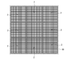
- the heat collector 2 of the second embodiment has a honeycomb structure including a plurality of cells 15 partitioned by partition walls 11 extending in a single direction, and the cells 15 flow channels through which the heat medium flows.
- a plurality of bases 10 of silicon carbide ceramic sintered body constituting the base unit 50 are joined through the joining layer 33 to form the base unit 50, and the first glass layer 21 covers the surface of the base unit 50.
- the surface of the first glass layer 21 is covered with the second glass layer 22. That is, in the second embodiment, the second glass layer 22 is the outermost layer of the base unit 50.
- symbol is attached
- the method of manufacturing the heat collector 2 of the second embodiment is different from the method of manufacturing the heat collector 2 of the first embodiment in that a plurality of substrates 10 are bonded with a bonding agent after the baking step, and the substrate unit 50.
- the joining process which forms is performed, and the 1st glass layer formation process and the 2nd glass layer formation process are performed after that. That is, the forming step, the firing step, the joining step, the first glass layer forming step, and the second glass layer forming step are performed in this order.
- a bonding agent is applied to the side surface of the substrate 10 of the silicon carbide ceramic sintered body having the honeycomb structure, and the plurality of substrates 10 are bonded to form the substrate unit 50.
- the bonding agent for example, coarse particles of silicon carbide (average particle size is 5 ⁇ m to 100 ⁇ m), fine particles of silicon carbide (average particle size is 5 ⁇ m or less), inorganic fibers such as mullite fibers, and binders
- a bonding agent in which (an inorganic binder such as colloidal silica and / or an organic binder such as carboxymethyl cellulose) is mixed can be used.
- the base unit 50 is heat-treated at a temperature of 80 ° C. to 100 ° C., whereby the bonding agent is dried and solidified to form the bonding layer 33.
- the surface of the base unit 50 (the partition walls 11 and the side surfaces of the base unit 50) is coated with the first coating agent (first coating step) and heated to vitrify the first coating agent to form the first glass layer 21.
- first coating step the surface of the first glass layer 21 covering the surface of the base unit 50 is coated with the second coating agent (second coating step), and the second coating agent is vitrified by heating to form the second glass layer 22 and (Second vitrification step).
- the heat collector 2 is formed in which the surface of the base unit 50 is covered with the first glass layer 21 and the surface is further covered with the second glass layer 22.
- FIG. 6 illustrates a case where the base unit 50 including nine bases 10 is covered with the first glass layer 21 and the second glass layer 22.
- FIG. 7 shows an example in which nine heat collectors 2 shown in FIG. 6 are accommodated in one casing 99 in 3 ⁇ 3 rows.
- the base unit 50 which is an aggregate of the base bodies 10 of the silicon carbide ceramic sintered body, is covered with the first glass layer 21 and the second glass layer 22 of silicate glass, Even when heated to a high temperature in the presence of oxygen, the oxidation of silicon carbide is effectively suppressed.
- the outermost layer of any of the heat collectors 2 is the second glass layer 22, and the second glass layer 22 has a silicic acid system in which the sum of the content ratios of the alkali metal component and the alkaline earth metal component is smaller than that of the first glass layer 21. Because it is glass, it is difficult to melt and soften at high temperatures. Therefore, even when a plurality of heat collectors 2 are adjacent to each other and used at a high temperature, the possibility that the adjacent heat collectors 2 are bonded to each other is reduced by the presence of the second glass layer 22. Thereby, the action which removes the heat collecting body 2 which deteriorated and damaged with use from the casing 99 is easy, and it can replace
- the mixed raw material having the following composition was mixed and kneaded with water, an organic binder, and a surfactant to obtain a kneaded product, and a formed body having a honeycomb structure was obtained by extrusion molding (molding step).
- the obtained molded body was fired at a temperature of 2300 ° C. for 10 minutes in a non-oxidizing atmosphere to obtain a silicon carbide ceramic sintered body (firing step).
- the substrate having a honeycomb structure had a rectangular column shape with a partition wall thickness of 0.4 mm and a size of 10 cm ⁇ 10 cm ⁇ 50 cm, and a cell density of 200 cells / square inch.
- the substrate obtained through the firing step was a porous body having an average pore diameter of 12 ⁇ m and an apparent porosity of 42%.
- the average pore diameter is the median diameter (the diameter when the cumulative pore volume is 50% of the total pore volume) from the pore diameter distribution measured by the mercury intrusion method using a mercury porosimeter (manufactured by Micromeritics, Autopore IV9500). ).
- the apparent porosity was calculated from the mercury volume and the sample volume that were pressed into the sample when measuring the average pore diameter.
- the substrate was impregnated with the first coating agent, and the substrate surface was coated with the first coating agent. Then, it heated at 1000 degreeC in the air atmosphere for 3 hours, and formed the 1st glass layer of the silicate type glass (1st glass layer formation process).
- a second coating agent was applied to the surface of the first glass layer and heated at 1000 ° C. for 3 hours in an air atmosphere to form a second glass layer of silicate glass. (Second glass layer forming step).
- the sample which passed through the 1st glass layer formation process and the 2nd glass layer formation process was made into the Example.
- the first coating agent a suspension obtained by mixing silicon dioxide, boron oxide, silicon (simple substance), silicon carbide, aluminum oxide, alkali metal / alkaline earth metal component, and other subcomponents with water.
- the second coating agent a suspension in which silicon dioxide, aluminum oxide, and other accessory components were mixed with water was used.
- the sum of the content of alkali metal component and alkaline earth metal component in the silicate glass formed after heating is 6.2% by mass in the first glass layer and 1.2% by mass in the second glass layer in terms of oxide. %Met.
- Example and Comparative Example A The sample of Example and Comparative Example A was subjected to a heating test in which the degree of oxidation of silicon carbide accompanying heating in an air atmosphere was evaluated by increasing the mass.
- the temperature was raised to 1200 ° C. or 1300 ° C., held at that temperature for 72 hours, and then cooled to room temperature for 8 times (total heating time of 576 hours). This was done by measuring the mass of the sample before and after. For each sample, a graph showing the change in mass with increasing heating time as a percentage of the initial mass (mass before starting the heating test) is shown in FIG.
- both the Example and Comparative Example A have a mass increase of about 4%. Thereafter, as the heating time increases, the mass is continuously increased in Comparative Example A having no silicate glass layer, whereas the mass is hardly changed in the example having the silicate glass layer. . And the ratio of the mass increase after completion
- the molecular weight of silicon carbide is 40 and the molecular weight of silicon dioxide is 60, when 1 mol of silicon carbide is oxidized to 1 mol of silicon dioxide, the mass increases by 20 g. Therefore, from the above results shown in FIG. 8, it was confirmed that the oxidation of silicon carbide was suppressed by forming a silicate glass layer (first glass layer and second glass layer) on the surface of the substrate.
- silicon carbide is also contained in the impregnated first coating agent. Therefore, in the first glass layer forming step, when all the silicon carbide in the first coating agent is not oxidized, the increase in mass in the heating test is due to the oxidation of silicon carbide derived from the first coating agent. The increase in mass will be included.
- the result of testing the difference in the sum of the content ratios of the alkali metal component and the alkaline earth metal component in the second glass layer, and the difference in adhesiveness between the heat collectors due to the presence or absence of the second glass layer Indicates.
- the difference in the sum of the content ratios of the alkali metal component and the alkaline earth metal component Tests were performed on Samples 1 to 8 that were subjected to the second glass layer forming step using the second coating agent and Comparative Example B that was not subjected to the second glass layer forming step.
- Table 1 the sum of the content ratios of the alkali metal component and the alkaline earth metal component in Samples 1 to 8 was varied in the range of 6% by mass to 0.6% by mass in terms of oxide.
- the adhesion test was performed as follows. Two identical samples were stacked one above the other with their side surfaces in contact, and in that state, heated in an air atmosphere at a temperature of 1300 ° C. for 576 hours. “ ⁇ ” indicates that the two stacked samples could be easily separated after cooling to room temperature, and “ ⁇ ” indicates that the two samples were adhered and could not be separated. It was evaluated with. The test was performed five times for each sample. The test results are also shown in Table 1.
- Samples 4 to 8 were evaluated as “ ⁇ ” in all tests, so that the sum of the content ratios of the alkali metal component and the alkaline earth component in the second glass layer was at least 0. In the range of 6% by mass to 3.0% by mass, it was confirmed that adhesion between adjacent heat collectors can be more reliably suppressed.
- the shape of the base body 10 is a quadrangular prism shape is illustrated by way of illustration.
- a base unit can be obtained.
- base units having different shapes for example, a triangular prism shape and a quadrangular prism shape
Landscapes
- Engineering & Computer Science (AREA)
- Physics & Mathematics (AREA)
- Life Sciences & Earth Sciences (AREA)
- Sustainable Development (AREA)
- Sustainable Energy (AREA)
- Thermal Sciences (AREA)
- Chemical & Material Sciences (AREA)
- Combustion & Propulsion (AREA)
- Mechanical Engineering (AREA)
- General Engineering & Computer Science (AREA)
- Ceramic Engineering (AREA)
- Ceramic Products (AREA)
Abstract
Description
骨材としての炭化珪素(平均粒子径12μm):75質量%
珪素源としての窒化珪素(平均粒子径10μm):20質量%
炭素源としての黒鉛(平均粒子径15μm):5質量%

Claims (8)
- 熱媒体を流通させる流路が形成された炭化珪素質セラミックス焼結体の基体と、
該基体の表面の少なくとも一部を被覆している、アルカリ金属成分及び/又はアルカリ土類金属成分を含有する珪酸系ガラスの第一ガラス層と、
該第一ガラス層を被覆している、アルカリ金属成分及びアルカリ土類金属成分の含有率の和が前記第一ガラス層より小さい珪酸系ガラスの第二ガラス層と
を具備することを特徴とする太陽熱発電用集熱体。 - 前記第二ガラス層におけるアルカリ金属成分及びアルカリ土類金属成分の含有率の和は、酸化物換算で3.6質量%以下である
ことを特徴とする請求項1に記載の太陽熱発電用集熱体。 - 前記基体が接合層を介して複数接合されて基体ユニットを形成しており、
前記第一ガラス層は前記基体ユニットの表面を被覆している
ことを特徴とする請求項1に記載の太陽熱発電用集熱体。 - 前記基体は、単一の方向に延びて列設された隔壁により区画された複数のセルを備えるハニカム構造を有し、前記セルが前記流路を構成している
ことを特徴とする請求項1に記載の太陽熱発電用集熱体。 - 前記基体が接合層を介して複数接合されて基体ユニットを形成しており、
前記第一ガラス層は前記基体ユニットの表面を被覆している
ことを特徴とする請求項2に記載の太陽熱発電用集熱体。 - 前記基体は、単一の方向に延びて列設された隔壁により区画された複数のセルを備えるハニカム構造を有し、前記セルが前記流路を構成している
ことを特徴とする請求項2に記載の太陽熱発電用集熱体。 - 前記基体は、単一の方向に延びて列設された隔壁により区画された複数のセルを備えるハニカム構造を有し、前記セルが前記流路を構成している
ことを特徴とする請求項3に記載の太陽熱発電用集熱体。 - 前記基体は、単一の方向に延びて列設された隔壁により区画された複数のセルを備えるハニカム構造を有し、前記セルが前記流路を構成している
ことを特徴とする請求項5に記載の太陽熱発電用集熱体。
Priority Applications (3)
| Application Number | Priority Date | Filing Date | Title |
|---|---|---|---|
| JP2015516868A JP5946961B2 (ja) | 2013-05-17 | 2013-05-17 | 太陽熱発電用集熱体 |
| PCT/JP2013/063846 WO2014184961A1 (ja) | 2013-05-17 | 2013-05-17 | 太陽熱発電用集熱体 |
| US14/760,594 US9857100B2 (en) | 2013-05-17 | 2013-05-17 | Heat collector for solar thermal power generation |
Applications Claiming Priority (1)
| Application Number | Priority Date | Filing Date | Title |
|---|---|---|---|
| PCT/JP2013/063846 WO2014184961A1 (ja) | 2013-05-17 | 2013-05-17 | 太陽熱発電用集熱体 |
Publications (1)
| Publication Number | Publication Date |
|---|---|
| WO2014184961A1 true WO2014184961A1 (ja) | 2014-11-20 |
Family
ID=51897966
Family Applications (1)
| Application Number | Title | Priority Date | Filing Date |
|---|---|---|---|
| PCT/JP2013/063846 WO2014184961A1 (ja) | 2013-05-17 | 2013-05-17 | 太陽熱発電用集熱体 |
Country Status (3)
| Country | Link |
|---|---|
| US (1) | US9857100B2 (ja) |
| JP (1) | JP5946961B2 (ja) |
| WO (1) | WO2014184961A1 (ja) |
Cited By (3)
| Publication number | Priority date | Publication date | Assignee | Title |
|---|---|---|---|---|
| JP2014224664A (ja) * | 2013-05-17 | 2014-12-04 | Jfeエンジニアリング株式会社 | 太陽熱発電用の集熱レシーバー及びその補修方法 |
| JP2016160103A (ja) * | 2015-02-26 | 2016-09-05 | Jfeスチール株式会社 | ハニカム構造体 |
| EP3561409B1 (en) * | 2016-12-26 | 2021-07-21 | Institute of Modern Physics, Chinese Academy of Sciences | Solar energy heat absorption device, solar energy heat collection system and solar energy power generation system |
Families Citing this family (1)
| Publication number | Priority date | Publication date | Assignee | Title |
|---|---|---|---|---|
| FR3075332B1 (fr) * | 2017-12-14 | 2020-04-03 | News | Absorbeur de rayonnements solaires, systeme et procede associe |
Citations (3)
| Publication number | Priority date | Publication date | Assignee | Title |
|---|---|---|---|---|
| JP2005015728A (ja) * | 2003-06-30 | 2005-01-20 | Wako:Kk | 無機塗料組成物 |
| JP2012093004A (ja) * | 2010-10-25 | 2012-05-17 | Ibiden Co Ltd | 集熱レシーバー及び太陽熱発電装置 |
| WO2013046732A1 (ja) * | 2011-09-30 | 2013-04-04 | 旭硝子株式会社 | 太陽熱集熱管用ガラス、太陽熱集熱管用ガラス管、および太陽熱集熱管 |
Family Cites Families (3)
| Publication number | Priority date | Publication date | Assignee | Title |
|---|---|---|---|---|
| US4121564A (en) * | 1977-02-04 | 1978-10-24 | Sanders Associates, Inc. | Solar energy receiver |
| DE2932170A1 (de) * | 1979-02-15 | 1980-08-21 | Haugeneder Hans | Bauwerkshuelle |
| JP5632704B2 (ja) | 2010-10-25 | 2014-11-26 | イビデン株式会社 | 集熱レシーバー及び太陽熱発電装置 |
-
2013
- 2013-05-17 US US14/760,594 patent/US9857100B2/en active Active
- 2013-05-17 WO PCT/JP2013/063846 patent/WO2014184961A1/ja active Application Filing
- 2013-05-17 JP JP2015516868A patent/JP5946961B2/ja active Active
Patent Citations (3)
| Publication number | Priority date | Publication date | Assignee | Title |
|---|---|---|---|---|
| JP2005015728A (ja) * | 2003-06-30 | 2005-01-20 | Wako:Kk | 無機塗料組成物 |
| JP2012093004A (ja) * | 2010-10-25 | 2012-05-17 | Ibiden Co Ltd | 集熱レシーバー及び太陽熱発電装置 |
| WO2013046732A1 (ja) * | 2011-09-30 | 2013-04-04 | 旭硝子株式会社 | 太陽熱集熱管用ガラス、太陽熱集熱管用ガラス管、および太陽熱集熱管 |
Cited By (3)
| Publication number | Priority date | Publication date | Assignee | Title |
|---|---|---|---|---|
| JP2014224664A (ja) * | 2013-05-17 | 2014-12-04 | Jfeエンジニアリング株式会社 | 太陽熱発電用の集熱レシーバー及びその補修方法 |
| JP2016160103A (ja) * | 2015-02-26 | 2016-09-05 | Jfeスチール株式会社 | ハニカム構造体 |
| EP3561409B1 (en) * | 2016-12-26 | 2021-07-21 | Institute of Modern Physics, Chinese Academy of Sciences | Solar energy heat absorption device, solar energy heat collection system and solar energy power generation system |
Also Published As
| Publication number | Publication date |
|---|---|
| US20160061492A1 (en) | 2016-03-03 |
| US9857100B2 (en) | 2018-01-02 |
| JP5946961B2 (ja) | 2016-07-06 |
| JPWO2014184961A1 (ja) | 2017-02-23 |
Similar Documents
| Publication | Publication Date | Title |
|---|---|---|
| JP4426083B2 (ja) | 炭化珪素質多孔体及びその製造方法 | |
| KR100607481B1 (ko) | 다공질 재료 및 그 제조 방법 | |
| CN103819219B (zh) | 一种耐酸碱腐蚀的碳化硅多孔支撑体 | |
| JP5946961B2 (ja) | 太陽熱発電用集熱体 | |
| JP5743486B2 (ja) | 集熱レシーバー及び太陽熱発電装置 | |
| WO2012105478A1 (ja) | 炭化珪素質材料、ハニカム構造体及び電気加熱式触媒担体 | |
| KR20050087828A (ko) | 탄화규소질 다공체 및 그 제조 방법, 그리고 허니컴 구조체 | |
| JPWO2004046063A1 (ja) | 炭化珪素質多孔体及びその製造方法、並びにハニカム構造体 | |
| JP5709007B2 (ja) | 蓄熱式バーナ用蓄熱体及び蓄熱式バーナ用蓄熱体の製造方法 | |
| CN102076628A (zh) | 制备多孔针状富铝红柱石材料体的方法 | |
| CN104529524A (zh) | 一种碳化硅多孔陶瓷及其制备方法 | |
| CN103119378A (zh) | 集热接收器及太阳能热发电装置 | |
| JP6059523B2 (ja) | シリカ接合体及びその製造方法 | |
| JP2008166312A (ja) | 真空チャック及びこれを用いた真空吸着装置 | |
| JP7247141B2 (ja) | 蓄熱体及び蓄熱体の製造方法 | |
| JP5085575B2 (ja) | 反応焼結炭化ケイ素構造体の製造方法 | |
| JP6407180B2 (ja) | ハニカム構造体及びハニカム構造体の製造方法 | |
| JP6560536B2 (ja) | 熱交換体及び熱交換体の製造方法 | |
| JP2016006373A (ja) | 熱交換体及び熱交換体の製造方法 | |
| JP4633449B2 (ja) | 炭化珪素質多孔体及びその製造方法 | |
| JP2000351679A (ja) | 炭化ケイ素質多孔体の製造方法および炭化ケイ素質多孔体 | |
| ES2558053B2 (es) | Colector de calor para la generación de energía térmica solar | |
| JP6667597B1 (ja) | コーティング剤の製造方法及びコーティング剤 | |
| WO2015019815A1 (ja) | 集熱レシーバー及び太陽熱発電装置 | |
| CN106810290A (zh) | 一种碳化硅多孔陶瓷的制备方法 |
Legal Events
| Date | Code | Title | Description |
|---|---|---|---|
| 121 | Ep: the epo has been informed by wipo that ep was designated in this application |
Ref document number: 13884855 Country of ref document: EP Kind code of ref document: A1 |
|
| ENP | Entry into the national phase |
Ref document number: 2015516868 Country of ref document: JP Kind code of ref document: A |
|
| WWE | Wipo information: entry into national phase |
Ref document number: 14760594 Country of ref document: US |
|
| WWE | Wipo information: entry into national phase |
Ref document number: P201590101 Country of ref document: ES |
|
| NENP | Non-entry into the national phase |
Ref country code: DE |
|
| 122 | Ep: pct application non-entry in european phase |
Ref document number: 13884855 Country of ref document: EP Kind code of ref document: A1 |