WO2014181764A1 - バッテリ式穿孔機 - Google Patents
バッテリ式穿孔機 Download PDFInfo
- Publication number
- WO2014181764A1 WO2014181764A1 PCT/JP2014/062136 JP2014062136W WO2014181764A1 WO 2014181764 A1 WO2014181764 A1 WO 2014181764A1 JP 2014062136 W JP2014062136 W JP 2014062136W WO 2014181764 A1 WO2014181764 A1 WO 2014181764A1
- Authority
- WO
- WIPO (PCT)
- Prior art keywords
- frame
- battery
- drilling
- wall portion
- machine according
- Prior art date
Links
Images


Classifications
-
- B—PERFORMING OPERATIONS; TRANSPORTING
- B23—MACHINE TOOLS; METAL-WORKING NOT OTHERWISE PROVIDED FOR
- B23B—TURNING; BORING
- B23B45/00—Hand-held or like portable drilling machines, e.g. drill guns; Equipment therefor
- B23B45/001—Housing of the drill, e.g. handgrip
-
- B—PERFORMING OPERATIONS; TRANSPORTING
- B23—MACHINE TOOLS; METAL-WORKING NOT OTHERWISE PROVIDED FOR
- B23B—TURNING; BORING
- B23B45/00—Hand-held or like portable drilling machines, e.g. drill guns; Equipment therefor
- B23B45/02—Hand-held or like portable drilling machines, e.g. drill guns; Equipment therefor driven by electric power
-
- B—PERFORMING OPERATIONS; TRANSPORTING
- B25—HAND TOOLS; PORTABLE POWER-DRIVEN TOOLS; MANIPULATORS
- B25H—WORKSHOP EQUIPMENT, e.g. FOR MARKING-OUT WORK; STORAGE MEANS FOR WORKSHOPS
- B25H1/00—Work benches; Portable stands or supports for positioning portable tools or work to be operated on thereby
- B25H1/0021—Stands, supports or guiding devices for positioning portable tools or for securing them to the work
- B25H1/0057—Devices for securing hand tools to the work
- B25H1/0064—Stands attached to the workpiece
- B25H1/0071—Stands attached to the workpiece by magnetic means
-
- B—PERFORMING OPERATIONS; TRANSPORTING
- B23—MACHINE TOOLS; METAL-WORKING NOT OTHERWISE PROVIDED FOR
- B23B—TURNING; BORING
- B23B2260/00—Details of constructional elements
- B23B2260/024—Batteries
Definitions
- the present invention relates to a portable drilling machine driven by a battery.
- a portable drilling machine includes a frame and a motor for rotating and driving a drilling tool such as a drill and is mounted so as to move up and down with respect to the frame, as described in Patent Document 1, for example. And a fixing portion that is provided at a lower portion of the frame and that removably fixes the drilling machine to the workpiece.
- the frame has an internal space, and a drive control unit that controls a motor and the like of the drilling drive unit, electrical wiring, and the like are disposed in the internal space.
- the frame is usually made of a metal casting in order to ensure sufficient strength. Therefore, the shape that can be produced is limited, the wall thickness is increased, and the size and weight of the entire apparatus are increased. It was.
- an object of the present invention is to provide a drilling machine using a battery, which can be made smaller and lighter than the conventional one.
- a lower surface wall portion removably attached to a workpiece to be perforated, and a frame having a front wall portion connected to the lower surface wall portion and extending upward from the lower surface wall portion to form an L shape with the lower surface wall portion;
- a drilling drive unit having a motor for rotationally driving the drilling tool, the drilling drive unit being attached to the front side of the front wall part, and the lower wall part being fixed to the workpiece,
- a perforation drive unit that is moved up and down along the front wall to move it closer to or away from the workpiece;
- a battery prepared separately from the frame and attached to the frame to hold a battery as a driving power source for the motor at a position behind the front wall and above the bottom wall.
- a housing With The frame provides a drilling machine configured to have a strength to support a load generated during the drilling by the drilling tool.
- a frame configured to support a drilling drive unit and to have a strength to support a load generated during drilling by a drilling tool, and a battery housing attached to the frame are provided as separate members.
- the mechanical strength of the battery housing may be small. Therefore, it is not necessary to make the casting as described above, it is possible to make it with resin, etc., and the degree of freedom in selecting the shape is increased, and the drilling machine can be made smaller and lighter. It becomes.
- an internal space for disposing a drive control circuit for controlling the motor can be formed between the frame and the battery housing.
- the battery housing includes a right part and a left part, and each of the right part and the left part can be attached to the frame.
- it may further include a fixing portion attached to the lower surface of the lower surface wall portion and removably fixing the lower surface wall portion to the workpiece.
- the fixing part may be an electromagnetic fixing part connected to the battery.
- electromagnet switch for activating the electromagnet fixing portion and a motor switch for activating the motor, wherein the electromagnet switch and the motor switch are on different sides of the battery housing. It can be made to be provided on the side surface.
- the drive control circuit can be arranged in parallel with the front wall portion or the lower wall portion of the frame in the internal space.
- the frame may be made of metal, and the battery housing may be made of resin.
- the L-shaped frame which is relatively heavy and supports the drilling drive unit that receives a large force from the drilling tool during drilling, has sufficient strength as a metal, but the battery housing that does not apply much force is made of resin By doing so, it becomes possible to reduce the weight of the entire apparatus.
- the battery housing that holds the battery is made of resin, so that a short circuit due to contact of the connection terminal of the battery with the metal member is prevented, and the battery that is normally covered with the resin housing is not attached to the battery housing. It is also possible to prevent the battery from being worn or damaged when it is attached and detached.
- the frame may have left and right ribs provided between left and right side edges of the lower wall portion and the front wall portion.
- the strength of the frame can be improved by providing left and right ribs.
- the battery housing includes an intermediate wall portion extending in parallel with the rear side of the front wall portion away from the front wall portion, and left and right side wall portions extending rearward from left and right side edges of the intermediate wall portion.
- the battery storage space for detachably storing the battery can be defined by the intermediate wall portion and the left and right side wall portions.
- the battery housing space for housing the battery is located at a position separated rearward from the front wall portion to which the drilling drive unit is attached, so that the relatively heavy drive control unit and the battery are separated in the front-rear direction. Since it is arranged, the weight balance of the entire device is improved and the device is less likely to fall, and a stable posture can be maintained even when it is carried. In addition, since the motor, which is a heating element, and the battery are arranged at positions separated from each other, efficient waste heat and cooling can be achieved.
- the battery housing space may further include a bottom wall part sandwiched between the left and right side wall parts, and the bottom wall part may be inclined downward from the front to the rear.
- This structure allows the water to be discharged naturally when it enters the battery housing space.
- a right handle portion is provided at an upper portion of the right portion of the housing
- a left handle portion is provided at an upper portion of the left portion of the housing
- the right portion and the left portion are attached to the frame.
- the right handle part and the left handle part form a single handle, and the right handle part and the left handle part are connected and fixed by screws extending from the right handle part to the left handle part. Can be.
- a dovetail groove is provided on the front surface of the front wall portion of the frame, and a slider that is slidably engaged with the dovetail groove may be provided on the perforation driving unit.
- the dovetail groove directly on the front wall of the frame, the number of parts can be reduced and the device can be made smaller.
- the drive control circuit is disposed at a lower position in the internal space, and a circuit member wired to the drive control circuit is provided at an upper position in the internal space.
- a partition plate that vertically divides the internal space between the drive control circuit and the circuit member, the partition plate having an opening that communicates in a vertical direction; and the opening includes the opening
- a sealing member is provided for sealing engagement with the wiring, and the wiring is wired through the opening and sealed to the partition plate by the sealing member.
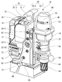
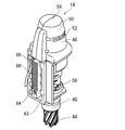
- FIG. 2 is a perspective view of the front left side of the drilling machine concerning one embodiment of the present invention.
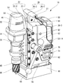
- FIG. 2 is a perspective view of the front right side of the drilling machine shown in FIG. 1. It is a fragmentary sectional view of the drilling machine shown in FIG. It is an exploded view of a main-body part.
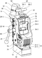
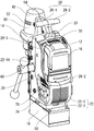
- FIG. 2 is a rear perspective view of the punching machine shown in FIG. 1 with a battery removed. It is a figure of the state with which the battery of the drilling machine shown in FIG. 5 was mounted
- the drilling machine 10 is attached to the front of the main body 12 so as to reciprocate in the vertical direction with respect to the main body 12.
- the drilling machine 10 is attached to the main body 12 by rotating the drilling tool 44 attached to the lower end of the drilling driving unit 14 by a motor 48 while being fixed at a predetermined drilling work position by the electromagnetic fixing unit 18.
- By rotating the feed handle 66 the drilling drive unit 14 is moved downward with respect to the main body unit 12 via a gear device composed of the rack 64 and the pinion 65, and the workpiece to be processed by the drilling tool 44 is moved. Drilling is performed.
- the main body 12 includes an L-shaped frame 20 including a front wall 20-1 to which the perforation driving unit 14 is attached and a lower wall 20-2 to which the electromagnetic fixing unit 18 is attached.
- the battery housing 22 is attached to the frame 20 so as to hold the battery 16 in a detachable manner.
- the frame 20 to which the perforation driving unit 14 and the electromagnetic fixing unit 18 to which a relatively large force is applied is directly attached is made of aluminum, and the necessary and sufficient strength is ensured. To reduce weight. Further, since the battery housing 22 is made of resin, even if a connection terminal (not shown) of the battery 16 is touched, it is not short-circuited.
- L-shaped frame here means that, for example, a part of the lower surface wall portion 20-2 extends further forward than the front wall portion 20-1, and the overall shape is L. Even if it is not a letter shape, if an L-shaped part is formed in the structure of the frame 20, such a frame is also included in this "L-shaped frame". I mean.
- the frame 20 includes a right rib 20-3 provided between the right edges of the front wall 20-1 and the lower wall 20-2 and a left rib 20- provided between the left edges. 4 and the right and left ribs 20-3 and 20-4 improve the strength of the frame 20 that supports the perforation driving unit 14.
- a shaft 23-1 to which the feed handle 66 is attached, and a pinion 65 for converting the rotation of the shaft by the feed handle 66 into the vertical movement of the drilling drive unit 14 (see FIG. 3 and FIG. 7), and a cylindrical gear mechanism portion 23 is provided in the handle attaching hole 20-8.
- the battery housing 22 includes a right part 22-1 and a left part 22-2 which are divided at a central part, and the right part 22-1 and the left part 22-2 sandwich the frame 20 from both left and right sides. Attached to the frame 20.
- an internal space 24 (FIG. 3) is formed between the battery housing 22 and the frame 20.
- a drive control circuit 36 (FIG. 4) is disposed in parallel with the front wall 20-1 at a position between the left and right ribs 20-3 and 20-4 in the internal space 24.
- the drive control circuit 36 controls the power supplied from the battery 16 to the motor 48 of the perforation drive unit 14 and the electromagnet 18-1 in the electromagnet fixing unit 18.
- the drive control circuit 36 may be disposed in parallel with the lower wall portion 20-2.
- the frame 20 is provided with engagement grooves 20-5 extending from the upper surface 20-12 of the front wall portion 20-1 to the lower ends of the right side surface 20-10 and the left side surface 20-11.
- the lower wall portion 20-2 includes an upper plate-like portion 20-2a and a lower block-like portion 20-2b integrally formed with the upper plate-like portion 20-2a.
- the battery housing 22 is provided with a front opening 22-4 for receiving the front wall 20-1 of the frame 20 and a lower surface opening 22-5 for receiving the lower wall 20-2. Further, the battery housing 22 is formed with an upper edge of the front opening 22-4 and an edge in the vertical direction and an edge 22-6 protruding inward along the edge of the lower opening 22-5.
- the protruding edge 22-6 is engaged with the engagement groove 20-5 of the frame and the lower surface 20-6 of the edge of the upper plate-like portion 20-2a. ing.
- the battery housing 22 is also formed with a protruding annular edge 22-8 that is engaged with the handle mounting hole 20-8 of the frame 20.
- the battery housing 22 has six protrusions that engage with circular engagement recesses 20-9 formed in the left and right ribs 20-3 and 20-4 of the frame 20 and are arranged in a circular shape. 22-9 is formed so that the engagement between the battery housing 22 and the frame 20 becomes stronger.
- the battery housing 22 is provided with a screw insertion hole 22-11 on each of the right side surface 22-14 and the left side surface 22-15 (FIG. 1), and the screw 82 (FIG. 1) is connected to the screw insertion hole 22-. 11, the battery housing 22 is fixed to the frame 20 by screwing into four screw holes 21 respectively provided on the right side surface 20-10 and the left side surface 20-11 of the frame 20.
- the right portion 22-1 and the left portion 22-2 are directly connected and fixed. Since the battery housing 22 is fixed to the frame 20 in many places in this way, stress concentration is less likely to occur even when a large force is applied to the battery housing 22, and the battery housing 22 is damaged. The risk of being reduced.
- the handle 26 provided on the upper part of the battery housing 22 includes a right handle 26-1 formed on the right portion 22-1 of the battery housing 22 and a left handle formed on the left portion 22-2.
- the right handle portion 26-1 and the left handle portion 26-2 are combined into one handle 26 (FIG. 1). ).
- the right handle portion 26-1 and the left handle portion 26-2 are connected and fixed by screws 27 (FIG. 2) extending from the right handle portion 26-1 to the left handle portion 26-2. This screw also functions as a reinforcing material to increase the strength of the handle 26.
- a battery housing space 28 for receiving the battery 16 is provided at the rear upper part of the battery housing 22, and the battery 16 is detachably mounted in the battery housing space 28.
- the battery housing space 28 is connected to the intermediate wall 28-1 and an intermediate wall 28-1 extending in parallel to the rear side of the front wall 20-1 of the frame 20 and extending away from the front wall 20-1.
- the space is defined as a space surrounded by a bottom wall 28-2 and a right wall 28-3 and a left wall 28-4 extending rearward from the left and right side edges of the intermediate wall 28-1.
- the upper part and the rear part of the battery housing space 28 are opened, and the battery 16 is slidably inserted into the battery housing space 28 from the opened upper part downward.
- the bottom wall portion 28-2 is slightly inclined downward from the front toward the rear, so that water that has entered the battery housing space 28 is naturally discharged.
- the connection terminal faces downward, so that water and dust are less likely to enter the battery 16.
- a battery cover 30 is provided on the upper portion of the battery housing 22 so as to be slidable in the front-rear direction.
- the battery cover 30 protrudes rearward from the battery housing 22 and is connected to the battery. 16 is in contact with the inclined cover engaging surface 16-1 (FIG. 3), and the battery 16 cannot be removed from the battery housing 22.
- the battery cover 30 partially covers the gap between the intermediate wall portion 28-1 of the battery housing 22 and the battery 16 from the upper part, chips, water, and the like are applied to the terminal portion of the battery 16. It becomes difficult to invade.
- the battery cover 30 is pushed forward and retracted into the battery housing 22, and then the battery 16 is pulled out upward.
- a switch engaging protrusion 30-1 protruding downward is provided at a portion of the battery cover 30 located in the battery housing 22, and the battery cover 30 protrudes rearward and the battery 16
- the limit switch 32 provided on the main body 12 is pressed to be turned on when it is in contact with the switch, and the limit switch 32 is turned off when retracted forward.
- the limit switch 32 is connected to a drive control circuit 36 disposed in the internal space 24, and is used to monitor whether the battery 16 is correctly installed and whether the battery 16 is in a state where it can be removed.
- the mounted battery 16 is electrically connected to the drive control circuit 36, and supplies power to the motor 48 and the electromagnetic fixing unit 18 via the drive control circuit 36.
- the electric power supplied from the battery 16 to the motor 48 and the electromagnetic fixing unit 18 is appropriately controlled by the drive control circuit 36.
- the perforation is made based on a signal from the drive control circuit 36.
- An LED display circuit 34 for displaying the state of the machine 10 on the LED display portion 33 (FIG. 1) on the upper side of the battery housing 22 is arranged so as to be visible from the outside of the battery housing 22.
- This LED display circuit 34 has green, yellow, and red LEDs, and the blinking state of these LEDs informs the operator of the remaining amount of the battery 16 and the degree of load on the motor 48, and warns when an abnormality occurs. To do.
- the limit switch 32 described above is disposed below the LED display circuit 34.
- the drive control circuit 36, the LED display circuit 34, and the limit switch 32 are electrically connected to each other by a wiring 35 covered with a shrinkable tube or the like.
- a partition plate 38 is provided in the battery housing 22 at a position between the drive control circuit 36, the LED display circuit 34, and the limit switch 32, and the lower internal space 24-2 in which the drive control circuit 36 is disposed is disposed in the LED. It is separated from the upper internal space 24-1 in which the display circuit 34 and the limit switch 32 are arranged. Specifically, as shown in FIG.
- a right partition plate 38-1 provided in the right portion 22-1 of the battery housing 22 and a left partition plate 38-2 provided in the left portion 22-2 are interposed therebetween.
- the L-shaped seal member 39 is attached to the opening so as to be hermetically engaged with the L-shaped opening.
- a wiring insertion hole 39-1 is formed in the central portion of the seal member 39, and the wiring 35 connected to the LED display circuit 34 and the limit switch 32 is passed through the wiring insertion hole 39-1 so as to be sealed. It has become.
- the partition plate 38 is provided so as to incline downward from the rear to the front, and a drain port 80 is formed in the front wall portion 20-1 of the frame 20 located in the upper internal space 24-1. ing.
- the upper internal space 24-1 is slidably received by the battery cover 30 protruding to the outside of the battery housing 22, and is not sealed with respect to the outside. Therefore, there is a risk that water such as rain may enter from the outside.
- the lower internal space 24-2 in which the drive control circuit 36 is located is not provided. The water can be discharged to the outside from the drain port 80 without entering. Thereby, it is possible to prevent the drive control circuit 36 from being damaged due to getting wet with water.
- the upper surface of the upper plate-like portion 20-2a is inclined downward from the front to the rear, and even if water enters the lower internal space 24-2, Water is also discharged to the outside from a drain groove 20-13 provided at the rear end.
- a drilling tool 44 such as a drill or an annular cutter is mounted on the arbor 40 located at the lower part of the drilling drive unit 14 attached to the front surface of the front wall 20-1 of the frame 20.
- the arbor 40 is connected to a motor 48 provided in a motor cover 46 on the upper part of the drilling drive unit 14 via a speed reducer 45, and the drilling tool 44 is driven by driving the motor 48. Is driven to rotate.
- a plurality of vent holes 52 are provided in the side surface 50 of the motor cover 46, and the motor 48 is cooled by air flowing into the inside from the vent holes 52.
- a plug 56 serving as a cutting oil injection port is provided on the left side surface of the drilling drive unit 14. By attaching a one-touch type socket with a hose to the plug 56, the cutting oil is added to the drilling tool 44 during drilling. To supply.
- dovetail grooves 62 extending in the vertical direction are formed on the left and right sides of the front wall portion 20-1 of the frame 20 as shown in FIG.
- a slider 63 having left and right side edges corresponding to the shape of the dovetail groove 62 is provided.
- the slider 63 is provided with a rack 64 (FIG. 8), and the frame 20 is provided with a pinion 65 (FIG. 7) that engages with the rack 64.
- the slider 20 has a right side surface 20-10 (FIG. 2).
- a feed handle 66 By manually rotating a feed handle 66 removably attached to the end of the projecting shaft 23-1, the pinion 65 is rotated to move the drilling drive unit 14 up and down relative to the frame 20. Yes.
- the feed handle 66 can be attached to the end of the shaft 23-1 protruding from the left side surface 20-11 of the frame 20, and can be attached to either the right or left depending on the situation.
- the wiring 68 extending from the motor 48 of the drilling drive unit 14 passes through the dovetail groove 62 and the wiring insertion path 69 (FIGS. 7 and 8) formed in the slider 63 and is in the internal space 24 of the main body 12. Therefore, it is connected to the drive control circuit 36 and is hardly exposed to the outside. By doing so, it is possible to prevent the wiring from being disconnected by applying an excessive force if the wiring is not caught.
- the electromagnet fixing unit 18 attached below the main body 12 generates a magnetic field by supplying electric power to the internal electromagnet 18-1, and is magnetically attracted to a magnetic material such as iron to fix the perforating machine 10. It comes to hold.
- a position adjustment mechanism 58 is provided between the electromagnet fixing portion 18 and the frame 20, and the position of the main body portion 12 is changed to an electromagnet type by turning a position adjustment handle 60 detachably attached to the position adjustment mechanism 58. The position can be adjusted from front to back and from side to side with respect to the fixed portion 18 so that the drilling position can be finely adjusted.
- the position adjustment handle 60 can be attached to the right side surface of the position adjustment mechanism 58.
- an electromagnet switch 70 for activating the electromagnet fixing portion 18 is provided on the left side surface 22-15 of the battery housing 22.
- a wall 72 is provided around the electromagnet switch 70 to prevent the electromagnet switch 70 from being inadvertently operated.
- the electromagnet switch 70 is turned off when the rear side (left side as viewed in FIG. 1) is pressed, but the wall 72 is raised at the rear side, and the electromagnet switch 70 is particularly turned on. It is difficult to switch to OFF by mistake.
- a motor switch 74 for starting the motor 48 is provided on the right side surface 22-14 of the battery housing 22.
- a wall 76 is also provided around the motor switch 74 so that the motor switch 74 is less likely to be inadvertently operated.
- the punching machine 10 is configured as described above with the aluminum L-shaped frame 20 and the resin battery housing 22 in which the main body portion 12 is separated, thereby reducing the overall size and weight of the apparatus.
- the relatively heavy battery 16 is arranged at a position separated rearward from the heavy drilling drive unit to improve the weight balance and achieve high stability, thereby preventing a fall during drilling.
- the portability is improved.
- the motor 48 and the battery 16 which are heating elements at positions separated by a resin having a low thermal conductivity, the influence of mutual heat is reduced and the cooling performance is improved.
- the front wall portion 20-1 and the lower wall portion 20-2 of the frame 20 are flat members, but may be configured by combining cylindrical or cylindrical members.
- the frame 20 is made of aluminum, it can be formed of other metal materials, non-metallic materials such as high-strength plastics, or a combination of a plurality of materials as long as a sufficient strength can be obtained.
- the battery housing 22 is made of resin, it can be formed of other materials including a metal material.
- the battery housing 22 is formed of a conductive material such as metal, a portion constituting the battery housing space 28, particularly It is also possible to prevent a short circuit of the battery 16 by configuring a portion that is likely to be touched by the connection terminal of the battery 16 with a non-conductive material such as a resin.
- the fixing part of the perforating machine 10 is not an electromagnet type, but may be a fixing part that employs other methods such as a permanent magnet or a clamping mechanism.
Landscapes
- Engineering & Computer Science (AREA)
- Mechanical Engineering (AREA)
- Drilling And Boring (AREA)
Abstract
Description
穿孔機において、
穿孔加工を受ける被加工物に取り外し可能に取り付けられる下面壁部、及び該下面壁部に連接し該下面壁部から上方に延びて該下面壁部とともにL型をなす前面壁部を有するフレームと、
穿孔工具を回転駆動するためのモータを有する穿孔駆動部であって、前記前面壁部の前側に取り付けられ、前記下面壁部が前記被加工物に固定された状態で、前記穿孔工具を該被加工物に対して近づけたり離したりするために前記前面壁部に沿って上下動される穿孔駆動部と、
前記フレームとは別体に用意され、該フレームに取り付けられて、前記モータの駆動電源としてのバッテリを、前記前面壁部の後側で且つ前記下面壁部の上側の位置に保持するためのバッテリハウジングと、
を備え、
前記フレームは、前記穿孔工具による前記穿孔加工の際に生じる負荷を支持する強度を有するようにされた、穿孔機を提供する。
Claims (14)
- 穿孔機において、
穿孔加工を受ける被加工物に取り外し可能に取り付けられる下面壁部、及び該下面壁部に連接し該下面壁部から上方に延びて該下面壁部とともにL型をなす前面壁部を有するフレームと、
穿孔工具を回転駆動するためのモータを有する穿孔駆動部であって、前記前面壁部の前側に取り付けられ、前記下面壁部が前記被加工物に固定された状態で、前記穿孔工具を該被加工物に対して近づけたり離したりするために前記前面壁部に沿って上下動される穿孔駆動部と、
前記フレームとは別体に用意され、該フレームに取り付けられて、前記モータの駆動電源としてのバッテリを、前記前面壁部の後側で且つ前記下面壁部の上側の位置に保持するためのバッテリハウジングと、
を備え、
前記フレームは、前記穿孔工具による前記穿孔加工の際に生じる負荷を支持する強度を有するようにされた、穿孔機。 - 前記フレームと前記バッテリハウジングとの間に前記モータを制御する駆動制御回路を配置するための内部空間が形成されるようにされた、請求項1に記載の穿孔機。
- 前記バッテリハウジングが右側部分及び左側部分からなり、該右側部分及び左側部分のそれぞれが前記フレームに取り付けられるようにされている、請求項1に記載の穿孔機。
- 前記下面壁部の下面に取り付けられ、前記下面壁部を前記被加工物に対して取り外し可能に固定する固定部をさらに備える、請求項1に記載の穿孔機。
- 前記固定部が前記バッテリに接続された電磁石式固定部である、請求項4に記載の穿孔機。
- 前記電磁石式固定部を起動するための電磁石スイッチと、前記モータを起動するためのモータスイッチとをさらに備え、前記電磁石スイッチと前記モータスイッチとが、前記バッテリハウジングの左右の異なる側の側面に設けられている、請求項5に記載の穿孔機。
- 前記駆動制御回路が、前記内部空間内において前記フレームの前記前面壁部又は前記下面壁部と並行に配置されるようにされた、請求項2に記載の穿孔機。
- 前記フレームが金属製であり、前記バッテリハウジングが樹脂製である、請求項1に記載の穿孔機。
- 前記フレームが、前記下面壁部および前記前面壁部の左右の両側縁間に設けられた左右のリブを有する、請求項1に記載の穿孔機。
- 前記バッテリハウジングが、前記前面壁部の後側で該前面壁部から離れて並行に延びる中間壁部と、該中間壁部の左右の両側縁から後方に延びる左右の側壁部とを有し、前記中間壁部と前記左右の側壁部とによって前記バッテリを着脱可能に収容するバッテリ収納空間を画定するようにされている、請求項1に記載の穿孔機。
- 前記バッテリ収容空間は前記左右の側壁部に挟まれた底面壁部をさらに有し、該底面壁部が前方から後方に向かって下方に傾斜している、請求項10に記載の穿孔機。
- 前記ハウジングの前記右側部分の上部には右側取っ手部が設けられ、前記ハウジングの前記左側部分の上部には左側取っ手部が設けられており、前記右側部分及び左側部分が前記フレームに取り付けられたときに前記右側取っ手部及び左側取っ手部が一つの取っ手を形成し、該右側取っ手部から左側取っ手部にまで延在するネジにより前記右側取っ手部及び左側取っ手部が連結固定されている、請求項3に記載の穿孔機。
- 前記フレームの前記前面壁部の前面にアリ溝が設けられ、前記穿孔駆動部に前記アリ溝と摺動係合するスライダが設けられている、請求項1に記載の穿孔機。
- 前記駆動制御回路は前記内部空間内の下方位置に配置され、前記内部空間内の上方位置には前記駆動制御回路と配線接続された回路部材が設けられており、前記バッテリハウジングは、前記駆動制御回路と前記回路部材との間で前記内部空間を上下に分割する仕切り板を有し、該仕切り板には上下方向に連通する開口部が設けられ、前記開口部には該開口部と密封係合するシール部材が設けられており、前記配線は、前記開口部を通って配線されて前記シール部材によって前記仕切り板に対して密封されている、請求項2又は7に記載の穿孔機。
Priority Applications (5)
| Application Number | Priority Date | Filing Date | Title |
|---|---|---|---|
| KR1020157034597A KR101823742B1 (ko) | 2013-05-08 | 2014-05-02 | 배터리식 천공기 |
| AU2014263591A AU2014263591B2 (en) | 2013-05-08 | 2014-05-02 | Battery-operated drilling machine |
| EP14794249.4A EP2995403B1 (en) | 2013-05-08 | 2014-05-02 | Battery-powered drilling machine |
| CN201480025064.5A CN105246625B (zh) | 2013-05-08 | 2014-05-02 | 蓄电池式钻孔机 |
| AU2017202536A AU2017202536B2 (en) | 2013-05-08 | 2017-04-18 | Battery-operated drilling machine |
Applications Claiming Priority (2)
| Application Number | Priority Date | Filing Date | Title |
|---|---|---|---|
| JP2013-098268 | 2013-05-08 | ||
| JP2013098268A JP5886786B2 (ja) | 2013-05-08 | 2013-05-08 | バッテリ式穿孔機 |
Publications (1)
| Publication Number | Publication Date |
|---|---|
| WO2014181764A1 true WO2014181764A1 (ja) | 2014-11-13 |
Family
ID=51867244
Family Applications (1)
| Application Number | Title | Priority Date | Filing Date |
|---|---|---|---|
| PCT/JP2014/062136 WO2014181764A1 (ja) | 2013-05-08 | 2014-05-02 | バッテリ式穿孔機 |
Country Status (7)
| Country | Link |
|---|---|
| EP (1) | EP2995403B1 (ja) |
| JP (1) | JP5886786B2 (ja) |
| KR (1) | KR101823742B1 (ja) |
| CN (1) | CN105246625B (ja) |
| AU (2) | AU2014263591B2 (ja) |
| TW (1) | TWI547329B (ja) |
| WO (1) | WO2014181764A1 (ja) |
Cited By (1)
| Publication number | Priority date | Publication date | Assignee | Title |
|---|---|---|---|---|
| US11845178B2 (en) | 2020-11-03 | 2023-12-19 | Techtronic Cordless Gp | Modular work station |
Families Citing this family (3)
| Publication number | Priority date | Publication date | Assignee | Title |
|---|---|---|---|---|
| JP5952777B2 (ja) * | 2013-05-29 | 2016-07-13 | 日東工器株式会社 | バッテリ式穿孔機 |
| WO2020195868A1 (ja) * | 2019-03-25 | 2020-10-01 | 日東工器株式会社 | バッテリ式電動工具 |
| CN113042780B (zh) * | 2021-04-22 | 2023-04-28 | 广州信诺船舶服务有限公司 | 一种细长孔加工装置及其方法 |
Citations (5)
| Publication number | Priority date | Publication date | Assignee | Title |
|---|---|---|---|---|
| JPS6196609U (ja) * | 1984-11-29 | 1986-06-21 | ||
| JPH0230410A (ja) * | 1988-07-14 | 1990-01-31 | Mineo Takeuchi | 消雪ノズルの補修に用いる工事用機械 |
| JPH0735698A (ja) | 1993-07-19 | 1995-02-07 | Canon Inc | 像読取り装置、表面状態検査装置及び該装置を備える露光装置 |
| JPH1128605A (ja) * | 1997-07-09 | 1999-02-02 | Nitto Kohki Co Ltd | 孔明け加工機 |
| JP2005074559A (ja) * | 2003-08-29 | 2005-03-24 | Nitto Kohki Co Ltd | 低丈型電動ドリル装置 |
Family Cites Families (17)
| Publication number | Priority date | Publication date | Assignee | Title |
|---|---|---|---|---|
| US2977825A (en) * | 1958-08-20 | 1961-04-04 | Buck Mfg Company | Electromagnetic drill support with auxiliary power supply |
| JPH0735698Y2 (ja) * | 1989-06-23 | 1995-08-16 | 日東工器株式会社 | 穿孔機 |
| JPH0748331Y2 (ja) * | 1989-07-24 | 1995-11-08 | 日東工器株式会社 | マグネットベースを具えた携帯式穿孔機の取付け装置 |
| US5126643A (en) * | 1991-06-24 | 1992-06-30 | Rotabroach Limited | Control system for hole cutting machines |
| US5342153A (en) * | 1993-05-14 | 1994-08-30 | Dobkins Edward L | Portable drill support with a work surface engaging base |
| JP3027538B2 (ja) * | 1996-05-28 | 2000-04-04 | 日東工器株式会社 | 穿孔機制御装置 |
| DE10064173C1 (de) * | 2000-12-22 | 2002-06-13 | Rothenberger Werkzeuge Ag | Bohrmaschine mit Elektromotor für Gesteinsbohrer |
| DE20108167U1 (de) * | 2001-05-15 | 2001-08-30 | Lehrberger Andreas | Handbohrmaschine mit Höhenführung zum Bohren von senkrechten Löchern und senkrechten Verschrauben |
| EP1389513A4 (en) * | 2001-05-21 | 2008-05-28 | Mitsubishi Materials Corp | DRILLING AND DRILLING |
| US6729414B2 (en) * | 2002-07-16 | 2004-05-04 | Black & Decker Inc. | Cordless drill with metal housing |
| CN2799134Y (zh) * | 2005-06-30 | 2006-07-26 | 吴彤 | 双机双控式磁座钻 |
| CN200948510Y (zh) * | 2006-09-27 | 2007-09-19 | 吕成远 | 一种改进的磁座钻 |
| US8376667B2 (en) * | 2007-07-27 | 2013-02-19 | Milwaukee Electric Tool Corporation | AC/DC magnetic drill press |
| JP2011251370A (ja) * | 2010-06-02 | 2011-12-15 | Kiso Kogyo:Kk | マグネットドリル |
| DE102011006279A1 (de) * | 2011-03-29 | 2012-10-04 | Metabowerke Gmbh | Bohrvorrichtung mit autarker Energiequelle |
| CN202539629U (zh) * | 2012-01-16 | 2012-11-21 | 吕成远 | 一种改良的磁座钻导滑结构 |
| JP6174432B2 (ja) * | 2013-03-29 | 2017-08-02 | 日東工器株式会社 | バッテリ式穿孔機 |
-
2013
- 2013-05-08 JP JP2013098268A patent/JP5886786B2/ja active Active
-
2014
- 2014-05-02 CN CN201480025064.5A patent/CN105246625B/zh active Active
- 2014-05-02 KR KR1020157034597A patent/KR101823742B1/ko active IP Right Grant
- 2014-05-02 WO PCT/JP2014/062136 patent/WO2014181764A1/ja active Application Filing
- 2014-05-02 EP EP14794249.4A patent/EP2995403B1/en active Active
- 2014-05-02 AU AU2014263591A patent/AU2014263591B2/en active Active
- 2014-05-07 TW TW103116236A patent/TWI547329B/zh active
-
2017
- 2017-04-18 AU AU2017202536A patent/AU2017202536B2/en active Active
Patent Citations (5)
| Publication number | Priority date | Publication date | Assignee | Title |
|---|---|---|---|---|
| JPS6196609U (ja) * | 1984-11-29 | 1986-06-21 | ||
| JPH0230410A (ja) * | 1988-07-14 | 1990-01-31 | Mineo Takeuchi | 消雪ノズルの補修に用いる工事用機械 |
| JPH0735698A (ja) | 1993-07-19 | 1995-02-07 | Canon Inc | 像読取り装置、表面状態検査装置及び該装置を備える露光装置 |
| JPH1128605A (ja) * | 1997-07-09 | 1999-02-02 | Nitto Kohki Co Ltd | 孔明け加工機 |
| JP2005074559A (ja) * | 2003-08-29 | 2005-03-24 | Nitto Kohki Co Ltd | 低丈型電動ドリル装置 |
Cited By (1)
| Publication number | Priority date | Publication date | Assignee | Title |
|---|---|---|---|---|
| US11845178B2 (en) | 2020-11-03 | 2023-12-19 | Techtronic Cordless Gp | Modular work station |
Also Published As
| Publication number | Publication date |
|---|---|
| KR101823742B1 (ko) | 2018-01-30 |
| AU2014263591A1 (en) | 2015-12-24 |
| JP2014217915A (ja) | 2014-11-20 |
| EP2995403A1 (en) | 2016-03-16 |
| CN105246625B (zh) | 2017-12-29 |
| KR20160005743A (ko) | 2016-01-15 |
| AU2017202536B2 (en) | 2018-11-22 |
| AU2014263591B2 (en) | 2017-05-04 |
| CN105246625A (zh) | 2016-01-13 |
| EP2995403A4 (en) | 2017-01-11 |
| JP5886786B2 (ja) | 2016-03-16 |
| TW201509569A (zh) | 2015-03-16 |
| TWI547329B (zh) | 2016-09-01 |
| AU2017202536A1 (en) | 2017-05-11 |
| EP2995403B1 (en) | 2020-04-15 |
Similar Documents
| Publication | Publication Date | Title |
|---|---|---|
| WO2014181764A1 (ja) | バッテリ式穿孔機 | |
| JP5952777B2 (ja) | バッテリ式穿孔機 | |
| JP5700266B2 (ja) | 電動工具 | |
| US8376667B2 (en) | AC/DC magnetic drill press | |
| US8627900B2 (en) | Electric power tool | |
| TWI547331B (zh) | Battery type punching machine | |
| JP5454777B2 (ja) | 電動工具 | |
| JP2020163568A (ja) | 電動工具 | |
| JP7220279B2 (ja) | バッテリ式電動工具 | |
| JP6728990B2 (ja) | 工具 | |
| JP6701653B2 (ja) | 電動工具 | |
| JP6606941B2 (ja) | 可搬型動力工具 | |
| JP7073364B2 (ja) | せん孔装置 |
Legal Events
| Date | Code | Title | Description |
|---|---|---|---|
| 121 | Ep: the epo has been informed by wipo that ep was designated in this application |
Ref document number: 14794249 Country of ref document: EP Kind code of ref document: A1 |
|
| WWE | Wipo information: entry into national phase |
Ref document number: 2014794249 Country of ref document: EP |
|
| NENP | Non-entry into the national phase |
Ref country code: DE |
|
| ENP | Entry into the national phase |
Ref document number: 20157034597 Country of ref document: KR Kind code of ref document: A |
|
| ENP | Entry into the national phase |
Ref document number: 2014263591 Country of ref document: AU Date of ref document: 20140502 Kind code of ref document: A |