WO2014181535A1 - 車両用空調装置 - Google Patents
車両用空調装置 Download PDFInfo
- Publication number
- WO2014181535A1 WO2014181535A1 PCT/JP2014/002418 JP2014002418W WO2014181535A1 WO 2014181535 A1 WO2014181535 A1 WO 2014181535A1 JP 2014002418 W JP2014002418 W JP 2014002418W WO 2014181535 A1 WO2014181535 A1 WO 2014181535A1
- Authority
- WO
- WIPO (PCT)
- Prior art keywords
- outside air
- vehicle
- case
- additional duct
- air
- Prior art date
- Legal status (The legal status is an assumption and is not a legal conclusion. Google has not performed a legal analysis and makes no representation as to the accuracy of the status listed.)
- Ceased
Links
Images

Classifications
-
- B—PERFORMING OPERATIONS; TRANSPORTING
- B60—VEHICLES IN GENERAL
- B60H—ARRANGEMENTS OF HEATING, COOLING, VENTILATING OR OTHER AIR-TREATING DEVICES SPECIALLY ADAPTED FOR PASSENGER OR GOODS SPACES OF VEHICLES
- B60H1/00—Heating, cooling or ventilating [HVAC] devices
- B60H1/00507—Details, e.g. mounting arrangements, desaeration devices
- B60H1/00557—Details of ducts or cables
- B60H1/00564—Details of ducts or cables of air ducts
-
- B—PERFORMING OPERATIONS; TRANSPORTING
- B60—VEHICLES IN GENERAL
- B60H—ARRANGEMENTS OF HEATING, COOLING, VENTILATING OR OTHER AIR-TREATING DEVICES SPECIALLY ADAPTED FOR PASSENGER OR GOODS SPACES OF VEHICLES
- B60H1/00—Heating, cooling or ventilating [HVAC] devices
- B60H1/00007—Combined heating, ventilating, or cooling devices
- B60H1/00021—Air flow details of HVAC devices
-
- B—PERFORMING OPERATIONS; TRANSPORTING
- B60—VEHICLES IN GENERAL
- B60H—ARRANGEMENTS OF HEATING, COOLING, VENTILATING OR OTHER AIR-TREATING DEVICES SPECIALLY ADAPTED FOR PASSENGER OR GOODS SPACES OF VEHICLES
- B60H1/00—Heating, cooling or ventilating [HVAC] devices
- B60H1/00507—Details, e.g. mounting arrangements, desaeration devices
- B60H1/00514—Details of air conditioning housings
- B60H1/00528—Connections between housing parts
-
- B—PERFORMING OPERATIONS; TRANSPORTING
- B60—VEHICLES IN GENERAL
- B60H—ARRANGEMENTS OF HEATING, COOLING, VENTILATING OR OTHER AIR-TREATING DEVICES SPECIALLY ADAPTED FOR PASSENGER OR GOODS SPACES OF VEHICLES
- B60H1/00—Heating, cooling or ventilating [HVAC] devices
- B60H1/00007—Combined heating, ventilating, or cooling devices
- B60H1/00021—Air flow details of HVAC devices
- B60H2001/00078—Assembling, manufacturing or layout details
- B60H2001/00085—Assembling, manufacturing or layout details of air intake
Definitions
- the present disclosure relates to a vehicle air conditioner that air-conditions a vehicle interior.
- the present invention relates to an inside / outside air switching device of a vehicle air conditioner that selectively sucks air from inside air and outside air and sends the air to an air conditioning duct.
- the vehicle air conditioner includes an air conditioning duct having a heat exchanger such as an evaporator or a condenser inside.
- An inside / outside air switching device is provided upstream of the air conditioning duct.
- a blower for sending conditioned air to an air conditioning duct of a vehicle air conditioner is housed in a blower casing.
- An inside / outside air case for accommodating a damper is provided at the upper end of the blower casing.
- One of the inside and outside air cases is provided with an inside air introduction port for introducing inside air, and the other is provided with an outside air introduction port for introducing outside air.
- This outside air inlet is provided on the vehicle side and is connected to the vehicle side outside air inlet for sucking outside air.
- a seal packing is sandwiched between the connection surfaces of the outside air introduction port and the vehicle side outside air suction port to seal the connection portion.
- an additional duct and set an additional duct having a different length for each vehicle and connect the inside / outside air case and the vehicle side outside air suction port with the additional duct.
- this additional duct must employ an airtight and waterproof structure by providing a seal packing between the additional duct and the vehicle-side outside air inlet.
- a structure in which the inside / outside air case and the additional duct can be coupled is required, and a very complicated structure is required.
- the present disclosure provides a vehicle that can connect an inside / outside air case to a vehicle-side outside air suction port without an additional duct or connect a vehicle-side outside air suction port and an inside / outside air case via an additional duct.
- the purpose is to provide an air conditioner for a vehicle.
- an air-conditioning duct provided with a heat exchanger that adjusts the temperature of the air-conditioning air, and a blower that is provided upstream of the air-conditioning duct and sends the air-conditioning air into the air-conditioning duct are provided inside.
- the seal surface part provided in the opening part end surface which connects the additional duct of the inside / outside air case, and configured to be connectable to the vehicle-side outside air suction port, and the convex part provided at the end part of the additional duct; And a concave portion that is provided on the seal surface portion and connects the inside / outside air case and the additional duct by fitting with the convex portion.
- an additional duct provided between the vehicle-side outside air intake port that is provided on the vehicle side and sucks outside air in order to send outside air into the inside and outside air case and the inside and outside air case. And it has the seal surface part which can be connected with a vehicle side outside air suction port in the part which connects the additional duct of an inside and outside air case. Therefore, when no additional duct is provided between the vehicle-side outside air suction port and the inside / outside air case, the vehicle-side outside air suction port and the inside / outside air case can be directly connected at the seal surface portion.
- an additional duct is provided between the vehicle-side outside air suction port and the inside / outside air case, a convex portion provided at an end portion of the additional duct is fitted into the concave portion of the seal surface portion.
- the inside / outside air case and the additional duct can be easily connected. That is, when connecting the vehicle-side outside air inlet and the inside / outside air case, an additional duct can be used or not used. Therefore, the inside / outside air case of the same standard (specification) can be used between vehicles having different dimensions.
- the end portion of the additional duct has an annular wall portion that enters the inside of the inside / outside air case rather than the seal surface portion when the additional duct and the inside / outside air case are connected.
- the water even if water enters along with the outside air from the vehicle-side outside air suction port, the water travels through the annular wall portion that enters the inside / outside air case rather than the seal surface portion, and the inside / outside air case Led inside. Therefore, water is not guided to the outside of the inside / outside air case through the additional duct and the inside / outside air case. Therefore, water can be prevented from entering an unexpected part in the vehicle.
- the seal surface portion has an annular flat portion for disposing the seal packing, and the flat portion has an outside air introduction port through which outside air is introduced on the inner peripheral side of the opening end surface.
- a recess is formed in the flat part.
- the seal surface portion has an annular flat portion for disposing a seal packing. Therefore, an annular seal packing is provided on the flat portion, and the vehicle-side outside air suction port can be reliably sealed and directly coupled to the inside / outside air case. Further, since the outside air is introduced to the inner peripheral side of the flat portion and the concave portion is formed in the flat portion, the sealing packing can be disposed on the flat portion.
- the convex portion is composed of an annular convex portion that annularly surrounds the outside air introduction port of the inside / outside air case, and the annular wall portion is provided on the inner peripheral side of the annular convex portion.
- the water is surrounded by both the annular wall portion on the inner peripheral side and the annular convex portion on the outer peripheral side. Water can be prevented from leaking outside the additional duct or inside / outside air case. Therefore, water can be prevented from entering an unexpected part in the vehicle.
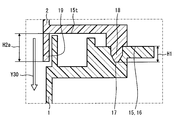
- FIG. 3 is a partially enlarged cross-sectional view of a portion indicated by Y3 in FIG. It is a partially expanded sectional view of the part shown by Y4 of FIG.
- FIG. 3 is a partially enlarged cross-sectional view of a portion along the arrow Y5-Y5 line of FIG.
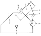
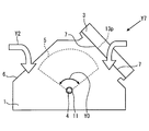
- FIG. 1 shows the relationship among the inside / outside air case 1, the additional duct 2, and the vehicle side outside air suction port 3 in the first embodiment.
- a damper 5 that rotates left and right about the shaft portion 4 is provided in the inside / outside air case 1.
- the vehicle-side outside air suction port 3 is actually an opening that takes in outside air provided in a partition wall that separates the engine room and the vehicle interior, but is schematically illustrated in FIG. 1 and the like.
- the case where the inside / outside air case 1 introduces air in the vehicle interior from the inside air introduction port 6 and the case where air outside the vehicle is introduced from the outside air introduction port 7 are switched. Yes.
- the inside air or outside air introduced into the inside / outside air case 1 is guided to a blower casing 8 connected to the inside / outside air case 1.
- a blower 9 including a centrifugal fan is provided in the blower casing 8. The blower 9 supplies conditioned air to the air conditioning duct 20.
- a heat exchanger (not shown) that cools or heats the conditioned air
- an air mix damper that adjusts the degree of cooling or heating, and the like are provided.
- the conditioned air that has flowed through the air conditioning duct 20 is guided into the vehicle compartment from an air outlet (not shown).
- a seal packing 23 ⁇ / b> P is provided between the vehicle-side outside air inlet 3 and the additional duct 2.
- An arrow Y1 indicates the flow of outside air introduced into the additional duct 2 via the vehicle-side outside air suction port 3.
- An arrow Y ⁇ b> 2 indicates a flow of the inside air in which the inside air that is air circulating in the vehicle interior is introduced into the inside / outside air case 1.
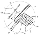
- FIG. 2 shows a connection state between the additional duct 2 and the inside / outside air case 1.
- the inside / outside air case 1 is provided with a shaft hole 11 into which the shaft of the damper 5 is inserted.
- the boundary between the inside / outside air case 1 and the additional duct 2 serves as the outside air introduction port 7 of the inside / outside air case 1.
- An outside air inlet 12 of the additional duct 2 is formed at the tip of the additional duct 2.
- the inside / outside air case 1 and the additional duct 2 are molded using the same synthetic resin, for example, polypropylene.
- FIG. 3 shows an enlarged view of the portion indicated by Y3 in FIG.
- the additional duct 2 and the inside / outside air case 1 are coupled by fitting.
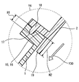
- FIG. 4 shows a part enlarged by Y4 in FIG. 2 and shows a fitting portion between the inside / outside air case 1 and the additional duct 2.
- FIG. 5 shows a partially enlarged portion along the line Y5-Y5 in FIG.
- FIG. 6 a state in which the inside / outside air case 1 and the vehicle side outside air inlet 3 of FIG. 1 are directly connected without providing the additional duct 2 will be described.
- a rubber seal packing 13p is provided at a connection portion between the vehicle-side outside air suction port 3 and the outside air introduction port 7 of the inside / outside air case 1.
- a seal surface portion 16 to be described later is formed at a portion where the additional duct 2 of the inside / outside air case 1 is connected.
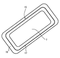
- FIG. 7 schematically shows the shape of the opening end face 15 of the outside air inlet 7 of the inside / outside air case 1 as seen from the direction indicated by the arrow Y7 in FIG.
- the inside / outside air case 1 and the additional duct 2 are connected as shown in FIG. 2, and in another case, the vehicle side outside air inlet 3 is directly connected to the inside / outside air as shown in FIG. It is attached to case 1.
- a part of the opening end face 15 forms a seal face portion 16 in close contact with the seal packing 13p.
- FIG. 7 will be described in which the opening end face 15 and the vehicle-side outside air suction port 3 are directly connected without using the additional duct 2.
- the air exiting the blower casing 8 flows into an air conditioning duct 20 provided with a heat exchanger (not shown) that adjusts the temperature of the conditioned air.
- a blower 9 for sending conditioned air to the air conditioning duct 20 is provided upstream of the air conditioning duct 20.
- the blower 9 is provided in a spiral blower casing 8.
- the blower 9 has a centrifugal fan that is rotated by a blower motor (not shown), and draws air from the center of the centrifugal fan into the inside / outside air case 1 as indicated by an arrow Y3.
- the inside / outside air case 1 has a damper 5 for selectively sending outside air outside the vehicle and inside air inside the vehicle into the blower casing 8.
- the air flow indicated by the arrow Y2 from the inside air inlet 6 selected by the damper 5 or the air flow of the outside air indicated by the arrow Y1 is caused by the rotation of the blower 9.
- the additional duct 2 is not provided between the vehicle side outside air suction port 3 provided on the vehicle side and the inside / outside air case 1, as shown in FIG.
- the inside / outside air case 1 can also be directly connected to the vehicle side outside air inlet 3.
- the configuration shown in FIG. 1 or the configuration shown in FIG. 6 depends on the type of vehicle on which the inside / outside air case 1 is provided. That is, according to the mounting dimension of the vehicle, the additional duct 2 can be provided as shown in FIG. 1 or the additional duct 2 can be omitted.
- the inside / outside air case 1 having a standard (specification) common to many vehicles can be used.
- the seal surface portion 16 is formed at a portion connecting the inside / outside air case 1 to the additional duct 2, and connects the inside / outside air case 1 and the additional duct 2. Further, the seal surface portion 16 is configured to be connectable to the vehicle-side outside air suction port 3.
- the seal surface portion 16 has a flat portion to which a seal packing (13p in FIG. 6) can be attached.
- the seal surface portion 16 is connected to the end of the additional duct 2 as shown in FIGS.
- the seal surface portion 16 is connected to the vehicle-side outside air suction port 3 via a seal packing 13p as shown in FIG.
- a concave portion 17 is formed in the seal surface portion 16 in an annular shape.
- the concave portion 17 is fitted with a convex portion 18 provided at an end portion of the additional duct 2.
- the convex portion 18 is formed in an annular shape at the end of the additional duct 2, and the fitting portions 17 and 18 are formed by fitting the convex portion 18 and the concave portion 17 as shown in FIGS. 3 to 5.
- an annular wall 19 is formed at the end of the additional duct 2.
- the wall portion 19 enters deeply into the inside / outside air case 1 on the inner peripheral side of the opening end face 15.
- the flat portion provided on the seal surface portion 16 (hereinafter, the flat portion is used with the same reference numeral 16 as the seal surface portion) is formed in an annular shape.
- a seal packing 13p is provided on the flat portion 16.
- the flat portion 16 is provided with a circular recess 17.
- an outside air introduction port 7 through which outside air is introduced is formed on the inner peripheral side of the flat portion 16. That is, the recess 17 is provided so as to surround the outside air introduction port 7.
- the convex portion 18 provided in the additional duct 2 surrounds the outside air introduction port 7 of the inside / outside air case 1 in an annular shape.
- the convex portion 18 is referred to as an annular convex portion 18.
- the annular wall portion 19 provided at the end of the additional duct 2 is provided on the inner peripheral side of the annular convex portion 18.
- the height H2 from the opening end surface 15 to the tip of the annular wall 19 is set higher than the height H1 from the opening end surface 15 to the tip of the convex portion 18.
- the height H2 from the opening end surface 15 to the tip of the annular wall 19 is set higher than the height H1 from the opening end surface 15 to the tip of the convex portion 18.
- the height H2a from the opening end face 15t on the additional duct 2 side to the tip of the annular wall 19 is set higher than the height H1 from the opening end face 15 to the tip of the convex part 18. ing.
- the height H ⁇ b> 1 of the convex portion 18 is defined from the opening end surface 15 on the inside / outside air case 1 side having the seal surface portion 16 where the additional duct 2 and the inside / outside air case 1 approach to the tip of the convex portion 18.
- the height H2a of the annular wall portion 19 is the height from the opening end surface 15t on the inside / outside air case 1 side of the additional duct 2 where the additional duct 2 and the inside / outside air case 1 approach each other to the tip of the annular wall portion 19. That's it.
- H1 and H2 (H2a) does not necessarily have to be greater than H1.
- H2 (H2a) water entering from the additional duct 2 side hardly leaks to the outside.
- the air-conditioning duct 20 provided with the heat exchanger which adjusts the temperature of an air-conditioning wind is provided.
- a blower casing 8 is provided on the upstream side of the air conditioning duct 20. Inside the blower casing 8, a blower 9 for sending conditioned air to the air conditioning duct 20 is provided.
- the blower casing 8 is provided with an inside / outside air case 1 having a damper 5 that selects and sends either outside air that is air outside the vehicle or inside air that is air circulating inside the vehicle.
- an additional duct 2 is provided between the vehicle side outside air suction port 3 provided on the vehicle side and sucking outside air and the inside / outside air case 1.
- the seal face 16 is provided on the opening end face 15 connecting the additional duct 2 of the inside / outside air case 1.
- the seal surface portion 16 includes a part of an opening end surface 15 connected to the vehicle-side outside air suction port 3 via a seal packing 13p.
- the seal surface portion 16 is fitted with a convex portion 18 provided at an end portion of the additional duct 2, and has a concave portion 17 that forms a fitting portion together with the convex portion 18. .
- the seal surface portion 16 provided on the opening end surface 15 of the inside / outside air case 1 serves as a connection surface that connects the additional duct 2 and a connection surface that connects the vehicle-side outside air suction port 3 via the seal packing 13p. Function. Therefore, the vehicle-side outside air suction port 3 can be provided in the inside / outside air case 1 via the additional duct 2, or the vehicle-side outside air suction port 3 can be directly connected to the inside / outside air case 1 via the seal packing 13p. . Therefore, when connecting the vehicle side outside air inlet 3 and the inside / outside air case 1, the additional duct 2 can be used or not used. Therefore, the inside and outside of the same standard (specification) can be used between vehicles having different dimensions. Qi case 1 can be used.
- the vehicle-side outside air suction port 3 When the vehicle-side outside air suction port 3 is directly connected to the inside / outside air case 1, it can be easily connected only by providing the seal packing 13 p on the seal surface portion 16.
- the additional duct 2 when the additional duct 2 is used, the inside / outside air case 1 and the additional duct 2 can be easily connected by fitting the convex portion 18 of the additional duct 2 into the concave portion 17 of the seal surface portion 16.
- the end of the additional duct 2 has an annular wall portion 19 that enters the inside of the inside / outside air case 1 rather than the seal surface portion 16.
- the seal surface part 16 has an annular flat part 16 for disposing the seal packing 13p (FIG. 6).
- the flat portion 16 has an outside air introduction port 7 through which outside air is introduced on the inner peripheral side of the flat portion 16, and a concave portion 17 is formed in the flat portion 16.
- the annular seal packing 13p is disposed on the flat portion 16 so that the vehicle-side outside air suction port 3 can be directly coupled to the inside / outside air case 1. Further, the periphery of the outside air introduction port 7 can be sealed with the sealing packing 13p provided on the flat portion 16.
- the convex portion 18 includes an annular convex portion 18 that annularly surrounds the outside air introduction port 7 of the inside / outside air case 1, and the annular wall portion 19 is provided on the inner peripheral side of the annular convex portion 18.
- the connection portion between the inside / outside air case 1 and the additional case 2 is doubly surrounded by the annular wall portion 19 on the inner peripheral side and the annular convex portion 18 on the outer peripheral side. ing. Therefore, even if water enters the inside of the additional duct 2 together with the outside air, it is possible to more reliably suppress water from leaking to the outside of the additional duct 2 or the inside / outside air case 1.
- the convex portion 18 and the annular wall portion 19 are arranged in parallel. 3 to 5, the height H2 from the opening end face 15 (15t) to the tip of the annular wall 19 is higher than the height H1 from the opening end face 15 to the tip of the convex part 18. (H2a) is higher.
- an annular shape from the opening end face 15 is higher than a height H ⁇ b> 1 from the opening end face 15 serving as an end face facing the additional duct 2 and the inside / outside air case 1 to the tip of the convex part 18.
- the height H2 up to the tip of the wall portion 19 is set higher.
- the height from the opening end face 15 that is the opposing end face of the additional duct 2 and the inside / outside air case 1 to the tip of the convex portion 18 is H1.
- the height H2a from the opening end surface 15t on the side of the additional duct 2 that is the opposite end surface of the additional duct 2 and the inside / outside air case 1 to the tip of the annular wall portion 19 is set higher than the height H1. .
- the annular wall portion 19 when connecting the inside / outside air case 1 and the additional duct 2, the annular wall portion 19 is first inserted into the inside / outside air case 1, and then the concave portion 17 of the opening end face 15 and the additional duct 2 are inserted. It is possible to fit the convex portion 18 provided at the end portion of this, and the assembly becomes easy. Further, since the height of the annular wall portion 19 is relatively high, it is possible to more reliably suppress water from leaking to the outside of the additional duct 2 or the inside / outside air case 1.
- the seal packing 23p (FIG. 1) between the vehicle-side outside air suction port 3 and the additional duct 2 and the seal packing 13p (FIG. 6) between the vehicle-side outside air suction port 3 and the inside / outside air case 1 are used as the vehicle-side outside air suction. It may be formed integrally with the mouth 3 or a separate packing may be attached.
- the entire surface of the seal surface portion 16 is the flat portion 16, but a part of the seal surface portion 16 may be a flat portion. That is, a non-flat portion may exist in the seal surface portion 16. That is, it is only necessary that a seal is formed using the seal packing 13p and the additional duct 2 and the inside / outside air case 1 can be connected.
- inside / outside air case 1 and the additional duct 2 are connected by fitting the concave portion 17 and the convex portion 18, but the inside / outside air case 1 and the additional duct are connected using a fastener such as a tapping screw (not shown). 2 may be connected.
Landscapes
- Physics & Mathematics (AREA)
- Thermal Sciences (AREA)
- Engineering & Computer Science (AREA)
- Mechanical Engineering (AREA)
- Air-Conditioning For Vehicles (AREA)
Priority Applications (1)
| Application Number | Priority Date | Filing Date | Title |
|---|---|---|---|
| US14/787,487 US20160068039A1 (en) | 2013-05-08 | 2014-05-07 | Vehicle air-conditioning device |
Applications Claiming Priority (2)
| Application Number | Priority Date | Filing Date | Title |
|---|---|---|---|
| JP2013-098726 | 2013-05-08 | ||
| JP2013098726A JP6131703B2 (ja) | 2013-05-08 | 2013-05-08 | 車両用空調装置 |
Publications (1)
| Publication Number | Publication Date |
|---|---|
| WO2014181535A1 true WO2014181535A1 (ja) | 2014-11-13 |
Family
ID=51867023
Family Applications (1)
| Application Number | Title | Priority Date | Filing Date |
|---|---|---|---|
| PCT/JP2014/002418 Ceased WO2014181535A1 (ja) | 2013-05-08 | 2014-05-07 | 車両用空調装置 |
Country Status (3)
| Country | Link |
|---|---|
| US (1) | US20160068039A1 (enExample) |
| JP (1) | JP6131703B2 (enExample) |
| WO (1) | WO2014181535A1 (enExample) |
Families Citing this family (2)
| Publication number | Priority date | Publication date | Assignee | Title |
|---|---|---|---|---|
| US9989252B2 (en) | 2013-08-22 | 2018-06-05 | Noritz Corporation | Exhaust adapter, exhaust structure for water heater, and method for installing exhaust adapter |
| US10436442B2 (en) * | 2015-10-28 | 2019-10-08 | Noritz Corporation | Exhaust tube holding member, exhaust structure for combustion apparatus, and method for installing exhaust structure for combustion apparatus |
Citations (6)
| Publication number | Priority date | Publication date | Assignee | Title |
|---|---|---|---|---|
| JPS62173208U (enExample) * | 1986-04-25 | 1987-11-04 | ||
| JPH06135220A (ja) * | 1992-10-26 | 1994-05-17 | Nippondenso Co Ltd | 車両用空調装置 |
| JPH08295118A (ja) * | 1995-04-25 | 1996-11-12 | Nippondenso Co Ltd | 車両用空気調和装置 |
| JP2003118352A (ja) * | 2001-10-17 | 2003-04-23 | Denso Corp | 車両用空調装置 |
| JP2011251555A (ja) * | 2010-05-31 | 2011-12-15 | Mitsubishi Heavy Ind Ltd | 車両用空気調和装置 |
| US20130156499A1 (en) * | 2011-12-19 | 2013-06-20 | Behr Gmbh & Co. Kg | Housing particularly for a motor vehicle hvac system |
Family Cites Families (4)
| Publication number | Priority date | Publication date | Assignee | Title |
|---|---|---|---|---|
| JPH08150825A (ja) * | 1994-11-28 | 1996-06-11 | Kasai Kogyo Co Ltd | ブロワーユニットの取付構造 |
| DE19725127B4 (de) * | 1996-06-17 | 2006-07-06 | Denso Corp., Kariya | Klimaanlage für ein Kraftfahrzeug |
| JPH10309924A (ja) * | 1997-05-12 | 1998-11-24 | Zexel Corp | 自動車用空調装置 |
| JP2004082800A (ja) * | 2002-08-23 | 2004-03-18 | Denso Corp | 車両用空調装置の内外気切替装置 |
-
2013
- 2013-05-08 JP JP2013098726A patent/JP6131703B2/ja not_active Expired - Fee Related
-
2014
- 2014-05-07 WO PCT/JP2014/002418 patent/WO2014181535A1/ja not_active Ceased
- 2014-05-07 US US14/787,487 patent/US20160068039A1/en not_active Abandoned
Patent Citations (6)
| Publication number | Priority date | Publication date | Assignee | Title |
|---|---|---|---|---|
| JPS62173208U (enExample) * | 1986-04-25 | 1987-11-04 | ||
| JPH06135220A (ja) * | 1992-10-26 | 1994-05-17 | Nippondenso Co Ltd | 車両用空調装置 |
| JPH08295118A (ja) * | 1995-04-25 | 1996-11-12 | Nippondenso Co Ltd | 車両用空気調和装置 |
| JP2003118352A (ja) * | 2001-10-17 | 2003-04-23 | Denso Corp | 車両用空調装置 |
| JP2011251555A (ja) * | 2010-05-31 | 2011-12-15 | Mitsubishi Heavy Ind Ltd | 車両用空気調和装置 |
| US20130156499A1 (en) * | 2011-12-19 | 2013-06-20 | Behr Gmbh & Co. Kg | Housing particularly for a motor vehicle hvac system |
Also Published As
| Publication number | Publication date |
|---|---|
| US20160068039A1 (en) | 2016-03-10 |
| JP2014218163A (ja) | 2014-11-20 |
| JP6131703B2 (ja) | 2017-05-24 |
Similar Documents
| Publication | Publication Date | Title |
|---|---|---|
| CN109196258B (zh) | 流路切换阀 | |
| CN103807916B (zh) | 空调器 | |
| US10792973B2 (en) | Blower device for air-conditioning of vehicle | |
| US7118355B2 (en) | Electric motor driven blower assembly with integral motor cooling duct | |
| JP4488075B2 (ja) | 電動送風機 | |
| US11274670B2 (en) | Blower | |
| KR20140098181A (ko) | 모터가 냉각되는 충격-흡수 팬 모터 장착부 | |
| CN106029410B (zh) | 汽车用空调装置 | |
| US11279207B2 (en) | Blower unit, and method of manufacturing blower unit | |
| US10215188B2 (en) | Blower | |
| WO2014181535A1 (ja) | 車両用空調装置 | |
| CN107531126B (zh) | 车辆用空调装置 | |
| US9616732B2 (en) | Air outlet for ventilating the interior of a motor vehicle | |
| WO2019220925A1 (ja) | 車両用空調ユニット | |
| KR101595326B1 (ko) | 차량의 에어컨디셔닝 댐퍼용 액츄에이터 | |
| JP2009156176A (ja) | 冷却装置 | |
| US20160039268A1 (en) | Hvac auxiliary duct attachment | |
| JP2010151412A (ja) | 室外ユニットの開口カバー | |
| KR200443748Y1 (ko) | 자동차용 공조장치의 덕트연결구조 | |
| JP2014218163A5 (enExample) | ||
| JP6718337B2 (ja) | 車両用空調装置 | |
| CN209479351U (zh) | 汽车空调风道及汽车 | |
| KR20060010493A (ko) | 송풍기용 인렛링과 에어 인테이크 덕트와의 결합구조 | |
| JP2006248351A (ja) | 空調装置のダクト接続構造 | |
| JP2007099230A (ja) | 車両用空調装置 |
Legal Events
| Date | Code | Title | Description |
|---|---|---|---|
| 121 | Ep: the epo has been informed by wipo that ep was designated in this application |
Ref document number: 14794713 Country of ref document: EP Kind code of ref document: A1 |
|
| WWE | Wipo information: entry into national phase |
Ref document number: 14787487 Country of ref document: US |
|
| NENP | Non-entry into the national phase |
Ref country code: DE |
|
| 122 | Ep: pct application non-entry in european phase |
Ref document number: 14794713 Country of ref document: EP Kind code of ref document: A1 |