WO2014178313A1 - マグネシウムイオン二次電池およびこれを用いた電池パック、並びにマグネシウムイオン二次電池用電解液 - Google Patents
マグネシウムイオン二次電池およびこれを用いた電池パック、並びにマグネシウムイオン二次電池用電解液 Download PDFInfo
- Publication number
- WO2014178313A1 WO2014178313A1 PCT/JP2014/061391 JP2014061391W WO2014178313A1 WO 2014178313 A1 WO2014178313 A1 WO 2014178313A1 JP 2014061391 W JP2014061391 W JP 2014061391W WO 2014178313 A1 WO2014178313 A1 WO 2014178313A1
- Authority
- WO
- WIPO (PCT)
- Prior art keywords
- magnesium
- ion secondary
- secondary battery
- ether
- magnesium ion
- Prior art date
- Legal status (The legal status is an assumption and is not a legal conclusion. Google has not performed a legal analysis and makes no representation as to the accuracy of the status listed.)
- Ceased
Links
Images
Classifications
-
- H—ELECTRICITY
- H01—ELECTRIC ELEMENTS
- H01M—PROCESSES OR MEANS, e.g. BATTERIES, FOR THE DIRECT CONVERSION OF CHEMICAL ENERGY INTO ELECTRICAL ENERGY
- H01M10/00—Secondary cells; Manufacture thereof
- H01M10/05—Accumulators with non-aqueous electrolyte
- H01M10/056—Accumulators with non-aqueous electrolyte characterised by the materials used as electrolytes, e.g. mixed inorganic/organic electrolytes
- H01M10/0564—Accumulators with non-aqueous electrolyte characterised by the materials used as electrolytes, e.g. mixed inorganic/organic electrolytes the electrolyte being constituted of organic materials only
- H01M10/0566—Liquid materials
- H01M10/0569—Liquid materials characterised by the solvents
-
- H—ELECTRICITY
- H01—ELECTRIC ELEMENTS
- H01M—PROCESSES OR MEANS, e.g. BATTERIES, FOR THE DIRECT CONVERSION OF CHEMICAL ENERGY INTO ELECTRICAL ENERGY
- H01M10/00—Secondary cells; Manufacture thereof
- H01M10/05—Accumulators with non-aqueous electrolyte
- H01M10/054—Accumulators with insertion or intercalation of metals other than lithium, e.g. with magnesium or aluminium
-
- H—ELECTRICITY
- H01—ELECTRIC ELEMENTS
- H01M—PROCESSES OR MEANS, e.g. BATTERIES, FOR THE DIRECT CONVERSION OF CHEMICAL ENERGY INTO ELECTRICAL ENERGY
- H01M10/00—Secondary cells; Manufacture thereof
- H01M10/05—Accumulators with non-aqueous electrolyte
- H01M10/056—Accumulators with non-aqueous electrolyte characterised by the materials used as electrolytes, e.g. mixed inorganic/organic electrolytes
- H01M10/0564—Accumulators with non-aqueous electrolyte characterised by the materials used as electrolytes, e.g. mixed inorganic/organic electrolytes the electrolyte being constituted of organic materials only
- H01M10/0566—Liquid materials
- H01M10/0568—Liquid materials characterised by the solutes
-
- H—ELECTRICITY
- H01—ELECTRIC ELEMENTS
- H01M—PROCESSES OR MEANS, e.g. BATTERIES, FOR THE DIRECT CONVERSION OF CHEMICAL ENERGY INTO ELECTRICAL ENERGY
- H01M10/00—Secondary cells; Manufacture thereof
- H01M10/42—Methods or arrangements for servicing or maintenance of secondary cells or secondary half-cells
- H01M10/425—Structural combination with electronic components, e.g. electronic circuits integrated to the outside of the casing
- H01M10/4257—Smart batteries, e.g. electronic circuits inside the housing of the cells or batteries
-
- H—ELECTRICITY
- H01—ELECTRIC ELEMENTS
- H01M—PROCESSES OR MEANS, e.g. BATTERIES, FOR THE DIRECT CONVERSION OF CHEMICAL ENERGY INTO ELECTRICAL ENERGY
- H01M2200/00—Safety devices for primary or secondary batteries
-
- H—ELECTRICITY
- H01—ELECTRIC ELEMENTS
- H01M—PROCESSES OR MEANS, e.g. BATTERIES, FOR THE DIRECT CONVERSION OF CHEMICAL ENERGY INTO ELECTRICAL ENERGY
- H01M2300/00—Electrolytes
- H01M2300/0017—Non-aqueous electrolytes
- H01M2300/0025—Organic electrolyte
- H01M2300/0028—Organic electrolyte characterised by the solvent
-
- Y—GENERAL TAGGING OF NEW TECHNOLOGICAL DEVELOPMENTS; GENERAL TAGGING OF CROSS-SECTIONAL TECHNOLOGIES SPANNING OVER SEVERAL SECTIONS OF THE IPC; TECHNICAL SUBJECTS COVERED BY FORMER USPC CROSS-REFERENCE ART COLLECTIONS [XRACs] AND DIGESTS
- Y02—TECHNOLOGIES OR APPLICATIONS FOR MITIGATION OR ADAPTATION AGAINST CLIMATE CHANGE
- Y02E—REDUCTION OF GREENHOUSE GAS [GHG] EMISSIONS, RELATED TO ENERGY GENERATION, TRANSMISSION OR DISTRIBUTION
- Y02E60/00—Enabling technologies; Technologies with a potential or indirect contribution to GHG emissions mitigation
- Y02E60/10—Energy storage using batteries
Definitions
- the present invention relates to a magnesium ion secondary battery, a battery pack using the same, and an electrolyte for a magnesium ion secondary battery.
- lithium ion secondary batteries represented by lithium ion secondary batteries and the like have been actively promoted as a clean energy source with a low environmental load.
- lithium ion secondary batteries are portable. It is widely used as a power source for electronic equipment.
- metallic lithium is an expensive material limited in terms of resources, and the safety of lithium ion batteries has been regarded as a problem due to the high activity of lithium.
- magnesium is abundant in resources and is much cheaper than lithium.
- a secondary battery using magnesium a high amount of electricity per unit volume and high safety can be expected. Therefore, recently, a magnesium ion secondary battery has been attracting attention, and research and development has been actively conducted.
- magnesium ion secondary batteries In the development of magnesium ion secondary batteries, the choice of electrolyte is extremely important. For example, not only water or a protic organic solvent but also an aprotic organic solvent such as esters and acrylonitrile cannot be used as a solvent constituting the electrolytic solution. This is because when these solvents are used, a passive film that does not allow magnesium ions to pass through is formed on the surface of the magnesium metal. This problem of passivating film formation is one of the obstacles to the practical use of magnesium ion secondary batteries.
- the magnesium ion secondary battery described above is expected to be used as a power source for electronic devices such as mobile phones and laptop computers, and electric vehicles.
- the ion secondary battery is exposed to a higher temperature atmosphere. Therefore, development of a magnesium ion secondary battery with more excellent heat resistance is desired.
- tetrahydrofuran as an electrolyte solution disclosed in JP 2012-182124 A described above has a low boiling point (boiling point: 66 ° C.), and therefore when a magnesium ion secondary battery is exposed to a high temperature atmosphere.
- the electrolytic solution is decomposed and gasified, cycle characteristics are deteriorated, the internal pressure of the battery is increased, and the battery is expanded.
- an electrolytic solution using tetrahydrofuran as a solvent has extremely low stability in a dry environment and is difficult to handle. Therefore, the magnesium ion secondary battery using tetrahydrofuran as the solvent for the electrolyte also has a problem that industrial production in a production line in a dry environment is extremely difficult. Therefore, a new proposal of an electrolytic solution for a magnesium ion secondary battery excellent in heat resistance and handleability is eagerly desired for practical use.
- a laminate-type thin secondary battery is generally manufactured by enclosing a power generation element formed by laminating a positive electrode, a separator, and a negative electrode, and an electrolytic solution in a laminate outer package. At this time, if bubbles remain in the laminate outer package (magnesium ion secondary battery), the battery characteristics may be deteriorated, and therefore the laminate package needs to be vacuum-sealed.
- An electrolyte using tetrahydrofuran having a low boiling point as a solvent has a problem that it tends to volatilize when vacuum-sealed in a laminate outer package.
- tetrahydrofuran is used as the electrolyte solvent, there is a problem that it is difficult to produce a laminate-type thin secondary battery.
- ethylene glycol dimethyl ether as a solvent for electrolyte disclosed in JP 2012-182124 A has a boiling point higher than that of tetrahydrofuran (boiling point: 85.2 ° C.).
- the electrolyte is less likely to volatilize when vacuum-sealed in the laminate outer package.
- charge / discharge characteristics in a magnesium ion secondary battery using an electrolytic solution containing ethylene glycol dimethyl ether as a solvent have not yet been confirmed.
- the present invention uses an electrolytic solution containing a high-boiling solvent, and has excellent heat resistance and handleability, and has excellent charge / discharge characteristics, and a magnesium ion secondary battery electrolysis for the magnesium ion secondary battery.
- An object is to provide a liquid and a magnesium ion secondary battery pack.
- a magnesium ion secondary battery according to the present invention is a magnesium ion secondary battery having a positive electrode, a negative electrode, and an electrolyte solution
- the electrolytic solution has the following general formula (1): (Where R 1 and R 2 are each independently an alkyl group having 1 to 6 carbon atoms, a phenyl group, or a cyclohexyl group.
- the alkyl group, the phenyl group, and the cyclohexyl group each have at least a portion of hydrogen substituted with fluorine. May have been n is an integer of 1 to 12.
- the ligand preferably has an alkyl group having 1 to 6 carbon atoms in which at least a part of hydrogen may be fluorine-substituted at a position furthest from the magnesium atom.
- the magnesium compound is preferably formed by bonding two disilazane groups to the magnesium atom.
- the magnesium compound is preferably magnesium bis (hexamethyldisilazide).
- the magnesium compound is preferably diisopropyl magnesium or dibutyl magnesium.
- the dialkyl glycol ether may be ethylene glycol dimethyl ether, diethylene glycol dimethyl ether, triethylene glycol dimethyl ether, tetraethylene glycol dimethyl ether, pentaethylene glycol dimethyl ether, hexaethylene glycol dimethyl ether, polyethylene glycol dimethyl ether, and triethylene glycol. It is preferably at least one selected from the group consisting of butyl methyl ether.
- the dialkyl glycol ether is preferably triethylene glycol dialkyl ether or tetraethylene glycol dialkyl ether.
- the dialkyl glycol ether is preferably at least one selected from the group consisting of triethylene glycol dimethyl ether, tetraethylene glycol dimethyl ether and triethylene glycol butyl methyl ether.
- the positive electrode, the negative electrode, and the electrolytic solution are sealed in a laminate outer package.
- An electrolyte for a magnesium ion secondary battery has the following general formula (1): (Where R 1 and R 2 are each independently an alkyl group having 1 to 6 carbon atoms, a phenyl group, or a cyclohexyl group. The alkyl group, the phenyl group, and the cyclohexyl group each have at least a portion of hydrogen substituted with fluorine. May have been n is an integer of 1 to 12.
- An electrolyte for a magnesium ion secondary battery comprising a mixture of a dialkyl glycol ether represented by the formula (I) and a magnesium compound in which two identical ligands are bonded to a magnesium atom, The ligand has a hydrophobic structure at a position farthest from the magnesium atom.
- the ligand preferably has an alkyl group having 1 to 6 carbon atoms in which at least a part of hydrogen may be fluorine-substituted at a position furthest from the magnesium atom.
- the magnesium compound is preferably formed by bonding two disilazane groups to the magnesium atom.
- the magnesium compound is preferably magnesium bis (hexamethyldisilazide).
- the magnesium compound is preferably diisopropyl magnesium or dibutyl magnesium.
- the dialkyl glycol ether may be ethylene glycol dimethyl ether, diethylene glycol dimethyl ether, triethylene glycol dimethyl ether, tetraethylene glycol dimethyl ether, pentaethylene glycol dimethyl ether, hexaethylene glycol dimethyl ether, polyethylene glycol dimethyl ether, and triethylene glycol. It is preferably at least one selected from the group consisting of butyl methyl ether.
- the dialkyl glycol ether is preferably triethylene glycol dialkyl ether or tetraethylene glycol dialkyl ether.
- the dialkyl glycol ether is preferably at least one selected from the group consisting of triethylene glycol dimethyl ether, tetraethylene glycol dimethyl ether, and triethylene glycol butyl methyl ether.
- a storage case, the magnesium ion secondary battery, and a protection circuit including an overcharge protection function and an overdischarge protection function are provided, and the magnesium ion secondary battery is provided in the storage case.
- a magnesium ion secondary battery pack in which the secondary battery and the protection circuit are housed is also provided.
- the heat resistance of the magnesium ion secondary battery can be improved by using the dialkyl glycol ether having a higher boiling point than that of conventional tetrahydrofuran as the solvent of the electrolytic solution.
- the dialkyl glycol ether having a higher boiling point than that of conventional tetrahydrofuran as the solvent of the electrolytic solution.
- a magnesium compound in which two identical ligands are bonded to a magnesium atom, and the ligand has a hydrophobic structure at a position farthest from the magnesium atom is used as a solute of the electrolytic solution.
- excellent charge / discharge characteristics can be exhibited in combination with the dialkyl glycol ether.
- a magnesium ion secondary battery, an electrolyte for magnesium ion secondary battery, and a magnesium ion secondary battery having excellent charge and discharge characteristics while using an electrolyte containing a high-boiling solvent and having excellent heat resistance and handleability Pack can be offered.
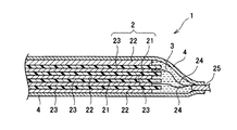
- FIG. 1 is a cross-sectional view illustrating a schematic configuration of a magnesium ion secondary battery according to an embodiment of the present invention
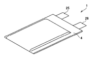
- FIG. 2 is a perspective view illustrating a schematic configuration of a magnesium ion secondary battery according to an embodiment of the present invention.
- the magnesium ion secondary battery 1 includes a laminate 2 in which sheet-like positive electrodes 21 and negative electrodes 22 are alternately stacked with separators 23 interposed therebetween, soot, and electrolysis.
- the liquid 3 a positive electrode lead wire 24 connected to the positive electrode 21, a negative electrode lead wire (not shown) connected to the negative electrode 22, and a laminate outer body 4 that stores them are provided.
- the positive electrode 21 includes a positive electrode current collector such as an aluminum plate, a gold plate, and a platinum plate having a thickness of about 10 to 100 ⁇ m, and a positive electrode that is provided on the positive electrode current collector and can reversibly insert and desorb magnesium ions.
- Active material examples include graphite fluoride ((CF)); manganese oxides such as mangan dioxide (MnO 2 ); (n) vanadium oxides such as divanadium pentoxide (V 2 O 5 ); sulfur And a sulfur compound; magnesium copper oxide (Mg x Cu y O z ); magnesium iron oxide (Mg x Fe y O z ); a chevrel compound and the like can be used.
- the negative electrode 22 includes a negative electrode current collector such as a copper plate, a gold plate, and a platinum plate having a thickness of about 10 to 100 ⁇ m, and a negative electrode active material that is provided on the negative electrode current collector and can supply magnesium ions (various magnesium Alloys, etc.). Note that a magnesium alloy plate may be used as the negative electrode 22 and may have both functions of the negative electrode current collector and the negative electrode active material.
- the positive electrode 21 is connected to a positive electrode external terminal 25 by a positive electrode lead wire 24, and the negative electrode 22 is connected to a negative electrode external terminal 26 by a negative electrode lead wire (not shown).
- Each of the positive electrode external terminal 25 and the negative electrode external terminal 26 is configured by one metal plate, and one end side thereof is sandwiched by the laminate outer package 4 and integrated with the laminate outer package 4, and the other end side is The laminate exterior body 4 protrudes outward.
- a separator 23 is provided between the positive electrode 21 and the negative electrode 22 for insulating them.
- the separator 23 For example, single layer or multilayer porous films, such as polyethylene, a polypropylene, a cellulose, etc. can be used.
- the electrolytic solution 3 contains a mixture of a predetermined magnesium compound as a solute and a predetermined dialkyl glycol ether as a solvent.
- a magnesium ion secondary battery having excellent heat resistance can be obtained.
- it can be set as the magnesium ion secondary battery excellent in the charge / discharge characteristic by combining the predetermined magnesium compound as a solute with the predetermined dialkyl glycol ether as a solvent.
- volatilization of the electrolyte solution 3 can be suppressed in the vacuum sealing step in the manufacturing process of the laminate type magnesium ion secondary battery.
- the said dialkyl glycol ether as a solvent is excellent in the handleability in a dry environment, it can be set as the magnesium ion secondary battery excellent in industrial productivity in a manufacturing line.
- the magnesium compound is a compound in which two ligands having the same molecular structure are bonded to a magnesium atom.
- the ligand has a hydrophobic structure at a position farthest from the magnesium atom.
- the “hydrophobic structure” means a molecular structure that can exhibit hydrophobicity, and a part of the molecular structure of the ligand may be a hydrophobic structure. The entire molecular structure may be a hydrophobic structure.
- magnesium ions are generated by breaking the bond between the two ligands of the magnesium compound.
- the bond of one ligand is cut, but the bond of the other ligand is cut. It is thought that it may remain without being. If one of the ligands is still bonded to the magnesium atom, it is considered difficult to form a stable complex ion (cation) with the dialkyl glycol ether.
- the two ligands bonded to the magnesium atom have the same molecular structure, so that even if the conditions for cutting the bond between the two ligands are substantially the same, It is thought that the bond of the ligand is cut together. Therefore, it is considered that complex ions (cations) are stably formed by dialkyl glycol ether and magnesium ions.
- Examples of the ligand include those having either an alkyl group having 1 to 6 carbon atoms or an alkyl group having 1 to 6 carbon atoms in which at least a part of hydrogen is fluorine-substituted at a position furthest from the magnesium atom.
- disilazane groups such as hexamethyldisilazane group
- alkyl groups having 1 to 6 carbon atoms such as methyl group, ethyl group, propyl group, isopropyl group, butyl group, pentyl group, hexyl group
- sulfonylimide group such as a lomethanesulfonylimide group and a trichloromethanesulfonylimide group are preferred.
- magnesium bis hexamethyldisilazide
- diisopropylmagnesium dibutylmagnesium
- magnesium bis (trifluoromethanesulfonylimide) and the like can be used.
- Dialkyl magnesium such as diisopropyl magnesium and dibutyl magnesium can be obtained, for example, by reacting metal magnesium with a halogenated hydrocarbon or alcohol.
- dialkyl glycol ether at least one of those having a chemical structure represented by the following general formula (1) can be used.
- R 1 and R 2 are each independently an alkyl group having 1 to 6 carbon atoms, a phenyl group, or a cyclohexyl group, and the alkyl group, the phenyl group, and the cyclohexyl group are at least a part of hydrogen. May be fluorine-substituted.
- N is an integer of 1 to 12, preferably an integer of 1 to 4.
- Examples of the alkyl group that can constitute R 1 and R 2 in the general formula (1) include a methyl group, an ethyl group, a propyl group, an isopropyl group, a butyl group, an isobutyl group, a pentyl group, an isopentyl group, and a hexyl group.
- Examples of the phenyl group in which at least a part of hydrogen atoms constituting R 1 and R 2 in the general formula (1) are substituted with halogen atoms include, for example, a 2-chlorophenyl group, a 3-chlorophenyl group, Chlorophenyl group, 2,4-dichlorophenyl group, 2-bromophenyl group, 3-bromophenyl group, 4-bromophenyl group, 2,4-dibromophenyl group, 2-iodophenyl group, 3-iodophenyl group, 4- Examples include iodophenyl group and 2,4-iodophenyl group.
- examples of the cyclohexyl group in which at least a part of hydrogen atoms constituting R 1 and R 2 in the general formula (1) are substituted with a halogen atom include a 2-chlorocyclohexyl group, a 3-chlorocyclohexyl group, 4-chlorocyclohexyl group, 2,4-dichlorocyclohexyl group, 2-bromocyclohexyl group, 3-bromocyclohexyl group, 4-bromocyclohexyl group, 2,4-dibromocyclohexyl group, 2-iodocyclohexyl group, 3iodocyclohexyl group 4-iodocyclohexyl group, 2,4-iodocyclohexyl group and the like.
- the dialkyl glycol ether as a solvent constituting the electrolytic solution according to the present invention has two carbons between two adjacent oxygen atoms in its chemical structure.
- dialkyl glycol ether examples include ethylene glycol dimethyl ether, diethylene glycol dimethyl ether, triethylene glycol dimethyl ether, tetraethylene glycol dimethyl ether, ethylene glycol diethyl ether, diethylene glycol diethyl ether, diethylene glycol dibutyl ether, pentaethylene glycol dimethyl ether, hexa
- examples include ethylene glycol dimethyl ether, polyethylene glycol dimethyl ether, and triethylene glycol butyl methyl ether.
- triethylene glycol dialkyl ether, tetraethylene glycol dialkyl ether, and the like having a higher boiling point are preferable, and triethylene glycol dimethyl ether, tetraethylene glycol dimethyl ether, triethylene glycol butyl methyl ether, and the like are particularly preferable.
- These dialkyl glycol ethers are preferably used because they are excellent in handleability in a dry environment.
- the peak current value of the cyclic voltammogram is Surprisingly, it is improved by about 120 to 190% as compared with the case of using the dialkyl glycol ether.
- a coordination formed by triethylene glycol dialkyl ether or tetraethylene glycol dialkyl ether such as triethylene glycol dimethyl ether, tetraethylene glycol dimethyl ether or triethylene glycol butyl methyl ether and magnesium ions.
- the coordinate structure is considered to be optimal for magnesium dissolution and precipitation, and the effect of improving the discharge rate characteristics can be expected.
- the concentration of the magnesium compound in the electrolytic solution may be a concentration that can ensure the conductivity required for the electrolytic solution, and is preferably 0.1 to 2 mol / L, for example, 0.5 to 1 mol / L. L is particularly preferred.
- the electrolytic solution may contain an additive such as aluminum chloride (AlCl 3 ) as long as the ion conductivity and the like of the electrolytic solution 3 are not impaired.
- AlCl 3 aluminum chloride
- the electrolytic solution can be prepared by dissolving an additive such as aluminum chloride in the dialkyl glycol ether and then mixing and dissolving the magnesium compound.
- the magnesium ion secondary battery according to the present invention may be one in which the positive electrode 21, the negative electrode 22, and the electrolytic solution 3 are sealed in the laminate outer package 4 as shown in FIGS. 1 and 2.
- the laminate outer package 4 one provided with a metal foil such as aluminum or stainless steel and a heat-sealing resin layer (modified polyolefin film or the like) provided on at least one side of the metal foil can be used.
- the metal foil may include a resin layer on the surface opposite to the surface on which the heat-sealing resin layer is provided.
- An adhesive layer (not shown) made of a polyolefin-based polymer or the like may be interposed between the laminate outer package 4 and the positive external terminal 25 and the negative external terminal 26.
- a magnesium ion secondary battery 1 according to the present invention has a configuration in which a laminate 2 and an electrolyte solution 3 are enclosed in a laminate outer package 4 in which a single metal laminate film is folded in two and the peripheral edge is fused.
- the present invention is not limited to such an embodiment, and the laminate 2 and the electrolytic solution 3 are enclosed in a laminate outer body 4 in which two metal laminate films are stacked and the peripheral edge is fused. You may have.
- the positive electrode lead wire 24 attached to the positive electrode 21 is connected to the positive electrode external terminal 25 after the laminate 2 is accommodated in the laminate outer package 4, and the negative electrode
- the negative electrode lead wire (not shown) attached to 22 is connected to the negative electrode external terminal 26, and the electrolyte solution 3 is filled into the laminate outer package 4 using a vacuum injection device or the like, and the laminate outer package 4 is sealed. Can be manufactured.
- the solvent constituting the electrolytic solution 3 in the present embodiment is the above-described dialkyl glycol ether having a relatively high boiling point, when the electrolytic solution 3 is filled and sealed in the laminate outer package 4 using a vacuum injection device or the like. Further, the volatilization of the electrolytic solution 3 is suppressed. Therefore, according to this embodiment, the effect that it becomes possible to manufacture the laminate type magnesium ion secondary battery 1 easily can be achieved.
- the dialkyl glycol ether having a relatively high boiling point is used as the solvent constituting the electrolytic solution, the heat resistance of the magnesium ion secondary battery can be improved. Further, as will be apparent from Examples described later, a magnesium ion secondary having good charge / discharge characteristics by combining the dialkyl glycol ether as a solvent in the mixture contained in the electrolyte and the magnesium compound as a solute. It can be a battery. Furthermore, since the solvent constituting the electrolytic solution is the above-described dialkyl glycol ether having a relatively high boiling point, an effect that the laminate-type magnesium ion secondary battery 1 can be easily manufactured can be achieved.
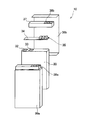
- FIG. 3 is an exploded perspective view showing the magnesium ion secondary battery pack in the present embodiment.
- the battery pack 10 includes a plurality of magnesium ion secondary batteries 1 according to the present embodiment accommodated in a battery case 30, and the battery case 30 includes a resin container 36 a, a resin container 36 b, and end portions.
- the case 37 is configured to be stored.
- a protective circuit board 34 for preventing overcharge and overdischarge is provided between the end case 37 and a surface of the battery case 30 that is provided on one end surface of the battery case 30 and includes the positive electrode terminal 32 and the negative electrode terminal 33. It has been.
- the positive external terminal 25 of each magnesium ion secondary battery 1 is connected to the positive terminal 32 and the negative external terminal 26 is connected to the negative terminal 33.
- the protective circuit board 34 includes an external connection connector 35.
- the external connection connector 35 is inserted into an external connection window 38a provided in the resin container 36a and an external connection window 38b provided in the end case 37. Connected with external terminals.
- the protection circuit board 34 is mounted with a charge / discharge safety circuit for controlling charge / discharge, a wiring circuit for connecting the external connection terminal and the magnesium ion secondary battery 1, and the like.
- the battery pack 10 can employ a known battery pack configuration as appropriate, except that the magnesium ion secondary battery 1 according to the present invention is used.
- the battery pack 10 appropriately includes a positive lead plate connected to the positive terminal 32, a negative lead plate connected to the negative terminal 33, an insulator, and the like between the battery case 30 and the end case 37. Also good.
- the battery case 30 including the magnesium ion secondary battery 1 is further provided with functions such as overcurrent blocking and battery temperature monitoring in addition to the above-described protection circuit, in addition to the usage mode for the battery pack. It may be an embodiment in which the secondary battery is integrated with the secondary battery itself. In such an embodiment, the battery pack can be used as a secondary battery having a protection function and a protection circuit without constituting a battery pack, and is highly versatile.
- the magnesium ion secondary battery 1 includes, as a power generation element, a laminate 2 in which a plurality of sheet-like positive electrodes 21 and negative electrodes 22 are alternately stacked via separators 23 therebetween.
- a laminate 2 in which a plurality of sheet-like positive electrodes 21 and negative electrodes 22 are alternately stacked via separators 23 therebetween.
- This invention is not limited to such an aspect, You may provide a pair of positive electrode 21 and negative electrode 22, and the separator 23 located between them as an electric power generation element.
- the laminated type magnesium ion secondary battery 1 provided with the laminated exterior body 4 was mentioned as an example, it demonstrated, this invention is not limited to such an aspect, A sheet-like positive electrode The aspect formed by inserting the winding-type electrode plate group wound in a spiral shape via 21, the negative electrode 22, and the separator 23 into a battery container (battery can etc.) may be used.
- Example 1 ⁇ Preparation of electrolyte> In an inert atmosphere glove box, aluminum chloride (0.177 g) was dissolved in triethylene glycol dimethyl ether (3.72 g), and then dibutyl magnesium (0.28 g) was dissolved to prepare an electrolytic solution.
- ⁇ Cyclic voltammetry evaluation> Rod-shaped nickel metal ( ⁇ : 0.90 mm, length: 0.8 cm) as a working electrode, rod-shaped magnesium metal ( ⁇ : 1.6 mm, length: 0.8 cm) as a counter electrode and a reference electrode, and Using the electrolyte prepared as described above, a three-electrode cell was assembled in a glove box in an inert atmosphere, and cyclic voltammetry evaluation was performed using this as a test cell. The cyclic voltammetry evaluation was performed by sweeping the potential to ⁇ 1.5 V, then sweeping to 2.7 V, and repeating this operation 30 times. The scanning speed was 10 mV / sec. As a result, it was possible to confirm the precipitation and dissolution of magnesium ions by a stable redox current. The peak current was about 1 mA.
- Molybdenum sulfide Molybdenum sulfide (Mo 6 S 8 , 5 g), acetylene black (0.3 g), carbon nanotube (manufactured by Showa Denko KK, VGCF (registered trademark), 0.2 g), KF polymer (6 g) and N-methylpyrrolidone ( NMP, 4 g) was mixed and stirred for 5 minutes at
- the positive electrode active material layer forming solution is applied to one side of a copper substrate (thickness: 10 ⁇ m) as a current collector, dried at 150 ° C., and 2 ton using a press.
- a positive electrode was produced by pressing at / cm.
- a magnesium alloy (AZ31, manufactured by Nippon Metals Co., Ltd., thickness: 45 ⁇ m) was prepared and used as a negative electrode.
- a sealed container (D-EL40H, manufactured by Dai Nippon Printing Co., Ltd.) composed of a laminate film with a propylene-based polymer layer on one side and a polymer layer on the other side, a separator (# 2500, manufactured by Celgard) ), And a laminated body with the positive electrode and the negative electrode facing each other is inserted, and the electrolyte solution is sealed in a sealed container using a vacuum liquid injection device (VS1616, manufactured by Sank Metal Co., Ltd.).
- a laminate type magnesium secondary battery 1 (laminate cell) was prepared.
- a sealant film (polyolefin polymer, manufactured by Hosen Co., Ltd.) was interposed between the positive electrode external terminal 25 and the negative electrode external terminal 26 and the inside of the sealed container (propylene polymer layer).
- Example 2 ⁇ Cyclic voltammetry evaluation> An electrolyte solution was prepared in the same manner as in Example 1 except that ethylene glycol dimethyl ether (4.32 g) was used instead of triethylene glycol dimethyl ether (3.72 g), and cyclic voltammetry evaluation was performed. As a result, it was possible to confirm the precipitation and dissolution of magnesium ions by a stable redox current. The peak current was about 0.8 mA.
- Example 3 ⁇ Cyclic voltammetry evaluation> An electrolytic solution was prepared in the same manner as in Example 1 except that tetraethylene glycol dimethyl ether (3.72 g) was used instead of triethylene glycol dimethyl ether (3.72 g), and cyclic voltammetry evaluation was performed. As a result, it was possible to confirm the precipitation and dissolution of magnesium ions by a stable redox current. The peak current was about 1 mA.
- Example 4 ⁇ Cyclic voltammetry evaluation> An electrolytic solution was prepared in the same manner as in Example 1 except that aluminum chloride was not added, and cyclic voltammetry evaluation was performed. As a result, it was possible to confirm the precipitation and dissolution of magnesium ions by a stable redox current. The peak current was about 0.6 mA.
- Example 5 ⁇ Cyclic voltammetry evaluation> An electrolytic solution was prepared in the same manner as in Example 1 except that triethylene glycol butyl methyl ether (3.72 g) was used instead of triethylene glycol dimethyl ether (3.72 g), and cyclic voltammetry evaluation was performed. As a result, it was possible to confirm the precipitation and dissolution of magnesium ions by a stable redox current. The peak current was about 1.5 mA.
- Example 6 Preparation of electrolyte> In an inert atmosphere glove box, aluminum chloride (1.33 g) was dissolved in triethylene glycol dimethyl ether (8.28 g), and then magnesium bis (hexamethyldisilazide) (1.72 g) was dissolved in the electrolysis. A liquid was prepared.
- Cyclic voltammetry evaluation was performed in the same manner as in Example 1 except that the above electrolytic solution was used.
- the cyclic voltammetry evaluation was performed by sweeping the potential to ⁇ 1.5 V, then sweeping to 2.7 V, and repeating this operation 30 times.
- the scanning speed was 10 mV / sec.
- Example 1 A laminate cell was produced in the same manner as in Example 1 except that the electrolytic solution was used, and a charge / discharge test was performed in the same manner as in Example 1 using the laminate cell. As a result, the discharge capacity was 42.4 mAh / g, and it was confirmed that charging and discharging were possible repeatedly, although there was some deterioration.
- a laminate cell was produced in the same manner as in Example 1 except that an electrolytic solution in which triethylene glycol dimethyl ether (3.72 g) was replaced with tetrahydrofuran (4.12 g) was used. However, the electrolyte was volatilized when the electrolytic solution was sealed, and a laminated cell capable of obtaining a stable voltage could not be produced.
- a laminate cell was produced in the same manner as in Example 1 except that an electrolytic solution in which triethylene glycol dimethyl ether (3.72 g) was replaced with dimethoxymethane (4.32 g) was used. However, when the electrolytic solution is sealed, the electrolyte is volatilized, and a laminate cell that can obtain a stable voltage cannot be manufactured.
- a laminate cell was produced in the same manner as in Example 1 except that an electrolytic solution in which triethylene glycol dimethyl ether (3.72 g) was replaced with methyl propyl ether (5.18 g) was used. However, when the electrolytic solution is sealed, the electrolyte is volatilized, and a laminate cell that can obtain a stable voltage cannot be manufactured.
- Example 2 A laminate cell was produced in the same manner as in Example 1 except that the above electrolytic solution was used. However, when the container in which the electrolytic solution is sealed is opened in a dry environment, the electrolytic solution has been altered. In addition, the electrolyte volatilizes when the electrolytic solution is sealed, and a laminate cell that can obtain a stable voltage cannot be manufactured.
- the electrolyte solution of Examples 1 to 5 (the electrolyte solution including a mixture of a predetermined dialkyl glycol ether (dialkyl glycol ether having two carbons between two adjacent oxygen atoms in the compound) and dialkyl magnesium)
- the precipitation and dissolution of magnesium ions can be confirmed by cyclic voltammetry evaluation, and the peak current is high, and it is confirmed that the battery characteristics are sufficient.
- the peak current is higher and excellent battery characteristics are exhibited. confirmed.
- magnesium ions are precipitated and dissolved by cyclic voltammetry evaluation. It was confirmed that the battery exhibited sufficient battery characteristics.
- an electrolytic solution obtained by combining triethylene glycol dimethyl ether as a solvent and magnesium bis (hexamethyldisilazide) as a solute does not cause a decomposition reaction due to an oxidation potential, and is used as an electrolytic solution for a magnesium ion secondary battery. It was confirmed that a magnesium ion secondary battery having a high energy density can be provided by using it.
- the electrolytic solution of Comparative Examples 1 to 3 electrolytic solution using an organic ether other than a predetermined dialkyl glycol ether (dialkyl glycol ether having two carbons between two adjacent oxygen atoms in the compound) as a solvent) was used.
- the precipitation and dissolution of magnesium ions could be confirmed by cyclic voltammetry evaluation, it was confirmed that the peak current was low and the battery characteristics were inferior.
- the magnesium ion secondary battery using the electrolytic solution of Comparative Example 4 electrolytic solution using magnesium chloride as a solute
- magnesium ion precipitation and dissolution could not be confirmed by cyclic voltammetry evaluation.
- a predetermined magnesium compound (bonded to a magnesium atom) as a solute in a predetermined dialkyl glycol ether (dialkyl glycol ether having two carbons between two adjacent oxygen atoms in the compound) as a solvent constituting the electrolytic solution. It was revealed that a magnesium ion secondary battery having good characteristics can be configured by combining two magnesium ligands having the same ligand.
- Example 1 it was possible to produce a laminate cell without volatilization of the electrolytic solution.
- Comparative Examples 1 to 3 and 8 the electrolytic solution was volatilized to produce a laminate cell. could not. From this result, by using dialkyl glycol ether (dialkyl glycol ether having two carbons between two adjacent oxygen atoms in the compound) as a solvent constituting the electrolytic solution, in the vacuum sealing step in the manufacturing process of the laminate cell It was confirmed that the volatilization of the electrolyte solution can be suppressed.
- dialkyl glycol ether dialkyl glycol ether having two carbons between two adjacent oxygen atoms in the compound
- dialkyl glycol ether having a high boiling point as an electrolyte solution solvent, it is possible to suppress the evaporation of the electrolyte solution in the vacuum sealing step in the production process of the laminate cell. It became clear that a type of magnesium ion secondary battery could be produced.
- Magnesium ion secondary battery 21 Positive electrode 22 . Negative electrode 3 . Electrolyte 4 . Laminated exterior body 10 . Battery pack (magnesium ion secondary battery pack)
Landscapes
- Chemical & Material Sciences (AREA)
- Engineering & Computer Science (AREA)
- General Chemical & Material Sciences (AREA)
- Manufacturing & Machinery (AREA)
- Chemical Kinetics & Catalysis (AREA)
- Electrochemistry (AREA)
- Physics & Mathematics (AREA)
- Condensed Matter Physics & Semiconductors (AREA)
- General Physics & Mathematics (AREA)
- Inorganic Chemistry (AREA)
- Materials Engineering (AREA)
- Secondary Cells (AREA)
- Sealing Battery Cases Or Jackets (AREA)
- Battery Mounting, Suspending (AREA)
Applications Claiming Priority (4)
| Application Number | Priority Date | Filing Date | Title |
|---|---|---|---|
| JP2013-095225 | 2013-04-30 | ||
| JP2013095225 | 2013-04-30 | ||
| JP2013-207031 | 2013-10-02 | ||
| JP2013207031A JP5799999B2 (ja) | 2013-04-30 | 2013-10-02 | マグネシウムイオン二次電池及びこれを用いた電池パック、並びにマグネシウムイオン二次電池用電解液 |
Publications (1)
| Publication Number | Publication Date |
|---|---|
| WO2014178313A1 true WO2014178313A1 (ja) | 2014-11-06 |
Family
ID=51843446
Family Applications (1)
| Application Number | Title | Priority Date | Filing Date |
|---|---|---|---|
| PCT/JP2014/061391 Ceased WO2014178313A1 (ja) | 2013-04-30 | 2014-04-23 | マグネシウムイオン二次電池およびこれを用いた電池パック、並びにマグネシウムイオン二次電池用電解液 |
Country Status (2)
| Country | Link |
|---|---|
| JP (1) | JP5799999B2 (https=) |
| WO (1) | WO2014178313A1 (https=) |
Cited By (1)
| Publication number | Priority date | Publication date | Assignee | Title |
|---|---|---|---|---|
| CN113363598A (zh) * | 2021-06-01 | 2021-09-07 | 松山湖材料实验室 | 新型水系镁金属二次电池其及制备方法 |
Families Citing this family (2)
| Publication number | Priority date | Publication date | Assignee | Title |
|---|---|---|---|---|
| WO2020027099A1 (ja) * | 2018-08-01 | 2020-02-06 | 株式会社村田製作所 | 電解液および電気化学デバイス |
| WO2020027340A1 (ja) * | 2018-08-01 | 2020-02-06 | 株式会社村田製作所 | 電解液および電気化学デバイス |
Citations (4)
| Publication number | Priority date | Publication date | Assignee | Title |
|---|---|---|---|---|
| JP2003512704A (ja) * | 1999-10-18 | 2003-04-02 | バル・イラン・ユニバーシティ | 高エネルギー、再充電可能、電気化学的セルの非水性電解液 |
| JP2012134082A (ja) * | 2010-12-24 | 2012-07-12 | Hitachi Ltd | 二次電池用正極活物質及びこれを用いたマグネシウム二次電池 |
| JP2012182124A (ja) * | 2011-02-28 | 2012-09-20 | Toyota Motor Corp | マグネシウム二次電池、電解液のマグネシウム二次電池における使用方法、及びマグネシウム二次電池用電解液 |
| WO2013015369A1 (ja) * | 2011-07-28 | 2013-01-31 | 和光純薬工業株式会社 | 電気化学デバイス用電解液 |
-
2013
- 2013-10-02 JP JP2013207031A patent/JP5799999B2/ja not_active Expired - Fee Related
-
2014
- 2014-04-23 WO PCT/JP2014/061391 patent/WO2014178313A1/ja not_active Ceased
Patent Citations (4)
| Publication number | Priority date | Publication date | Assignee | Title |
|---|---|---|---|---|
| JP2003512704A (ja) * | 1999-10-18 | 2003-04-02 | バル・イラン・ユニバーシティ | 高エネルギー、再充電可能、電気化学的セルの非水性電解液 |
| JP2012134082A (ja) * | 2010-12-24 | 2012-07-12 | Hitachi Ltd | 二次電池用正極活物質及びこれを用いたマグネシウム二次電池 |
| JP2012182124A (ja) * | 2011-02-28 | 2012-09-20 | Toyota Motor Corp | マグネシウム二次電池、電解液のマグネシウム二次電池における使用方法、及びマグネシウム二次電池用電解液 |
| WO2013015369A1 (ja) * | 2011-07-28 | 2013-01-31 | 和光純薬工業株式会社 | 電気化学デバイス用電解液 |
Cited By (1)
| Publication number | Priority date | Publication date | Assignee | Title |
|---|---|---|---|---|
| CN113363598A (zh) * | 2021-06-01 | 2021-09-07 | 松山湖材料实验室 | 新型水系镁金属二次电池其及制备方法 |
Also Published As
| Publication number | Publication date |
|---|---|
| JP5799999B2 (ja) | 2015-10-28 |
| JP2014232719A (ja) | 2014-12-11 |
Similar Documents
| Publication | Publication Date | Title |
|---|---|---|
| JP5449522B2 (ja) | 空気電池 | |
| JP5253905B2 (ja) | 非水電解液および非水電解液二次電池 | |
| US8637192B2 (en) | Nonaqueous electrolytic solution containing magnesium ions, and electrochemical device using the same | |
| JP7062155B2 (ja) | 二次電池用電解質及びこれを含む二次電池 | |
| CN106025270B (zh) | 电化学能存储装置 | |
| KR20110030666A (ko) | 비수 용매, 및 그것을 사용한 비수 전해액 및 비수계 이차 전지 | |
| US10020539B2 (en) | Nonaqueous electrolyte secondary battery and battery pack | |
| JP6767151B2 (ja) | 非水系電解液及び非水系二次電池 | |
| JP5723186B2 (ja) | 非水電解液、およびリチウムイオン二次電池 | |
| CN105409048A (zh) | 作为锂离子电池中电解质用添加剂的马来腈衍生物 | |
| JP6730284B2 (ja) | 電極の製造方法及び蓄電デバイスの製造方法 | |
| JP2025541546A (ja) | 二次電池用電解液、二次電池、電池モジュール、電池パック及び電力消費装置 | |
| JP2017010865A (ja) | 二次電池 | |
| JP5799999B2 (ja) | マグネシウムイオン二次電池及びこれを用いた電池パック、並びにマグネシウムイオン二次電池用電解液 | |
| JP2015213082A (ja) | マグネシウムイオン二次電池及びこれを用いた電池パック、並びにマグネシウムイオン二次電池用電解液 | |
| JP4880930B2 (ja) | 非水電解液及びリチウム二次電池 | |
| JP5763161B2 (ja) | 空気電池 | |
| JP7618297B2 (ja) | リチウム2次電池 | |
| JP4826699B2 (ja) | 蓄電デバイス | |
| JP2019129119A (ja) | イオン伝導性セパレータ及び電気化学デバイス | |
| JP6875818B2 (ja) | 電解液ならびにそれを用いた電気化学デバイス | |
| JP7788741B2 (ja) | リチウム2次電池 | |
| JPWO2018221676A1 (ja) | 電解液及び電気化学デバイス | |
| JP2014044896A (ja) | 非水電解質空気電池及びその使用方法 | |
| JP5245864B2 (ja) | 蓄電デバイス |
Legal Events
| Date | Code | Title | Description |
|---|---|---|---|
| 121 | Ep: the epo has been informed by wipo that ep was designated in this application |
Ref document number: 14791268 Country of ref document: EP Kind code of ref document: A1 |
|
| NENP | Non-entry into the national phase |
Ref country code: DE |
|
| 122 | Ep: pct application non-entry in european phase |
Ref document number: 14791268 Country of ref document: EP Kind code of ref document: A1 |