WO2014178118A1 - 車両制御装置 - Google Patents
車両制御装置 Download PDFInfo
- Publication number
- WO2014178118A1 WO2014178118A1 PCT/JP2013/062639 JP2013062639W WO2014178118A1 WO 2014178118 A1 WO2014178118 A1 WO 2014178118A1 JP 2013062639 W JP2013062639 W JP 2013062639W WO 2014178118 A1 WO2014178118 A1 WO 2014178118A1
- Authority
- WO
- WIPO (PCT)
- Prior art keywords
- clutch
- rotating machine
- stroke
- change
- rotation angle
- Prior art date
- Legal status (The legal status is an assumption and is not a legal conclusion. Google has not performed a legal analysis and makes no representation as to the accuracy of the status listed.)
- Ceased
Links
Images


Classifications
-
- F—MECHANICAL ENGINEERING; LIGHTING; HEATING; WEAPONS; BLASTING
- F16—ENGINEERING ELEMENTS AND UNITS; GENERAL MEASURES FOR PRODUCING AND MAINTAINING EFFECTIVE FUNCTIONING OF MACHINES OR INSTALLATIONS; THERMAL INSULATION IN GENERAL
- F16D—COUPLINGS FOR TRANSMITTING ROTATION; CLUTCHES; BRAKES
- F16D48/00—External control of clutches
- F16D48/06—Control by electric or electronic means, e.g. of fluid pressure
-
- B—PERFORMING OPERATIONS; TRANSPORTING
- B60—VEHICLES IN GENERAL
- B60K—ARRANGEMENT OR MOUNTING OF PROPULSION UNITS OR OF TRANSMISSIONS IN VEHICLES; ARRANGEMENT OR MOUNTING OF PLURAL DIVERSE PRIME-MOVERS IN VEHICLES; AUXILIARY DRIVES FOR VEHICLES; INSTRUMENTATION OR DASHBOARDS FOR VEHICLES; ARRANGEMENTS IN CONNECTION WITH COOLING, AIR INTAKE, GAS EXHAUST OR FUEL SUPPLY OF PROPULSION UNITS IN VEHICLES
- B60K6/00—Arrangement or mounting of plural diverse prime-movers for mutual or common propulsion, e.g. hybrid propulsion systems comprising electric motors and internal combustion engines
- B60K6/20—Arrangement or mounting of plural diverse prime-movers for mutual or common propulsion, e.g. hybrid propulsion systems comprising electric motors and internal combustion engines the prime-movers consisting of electric motors and internal combustion engines, e.g. HEVs
- B60K6/22—Arrangement or mounting of plural diverse prime-movers for mutual or common propulsion, e.g. hybrid propulsion systems comprising electric motors and internal combustion engines the prime-movers consisting of electric motors and internal combustion engines, e.g. HEVs characterised by apparatus, components or means specially adapted for HEVs
- B60K6/36—Arrangement or mounting of plural diverse prime-movers for mutual or common propulsion, e.g. hybrid propulsion systems comprising electric motors and internal combustion engines the prime-movers consisting of electric motors and internal combustion engines, e.g. HEVs characterised by apparatus, components or means specially adapted for HEVs characterised by the transmission gearings
-
- B—PERFORMING OPERATIONS; TRANSPORTING
- B60—VEHICLES IN GENERAL
- B60K—ARRANGEMENT OR MOUNTING OF PROPULSION UNITS OR OF TRANSMISSIONS IN VEHICLES; ARRANGEMENT OR MOUNTING OF PLURAL DIVERSE PRIME-MOVERS IN VEHICLES; AUXILIARY DRIVES FOR VEHICLES; INSTRUMENTATION OR DASHBOARDS FOR VEHICLES; ARRANGEMENTS IN CONNECTION WITH COOLING, AIR INTAKE, GAS EXHAUST OR FUEL SUPPLY OF PROPULSION UNITS IN VEHICLES
- B60K6/00—Arrangement or mounting of plural diverse prime-movers for mutual or common propulsion, e.g. hybrid propulsion systems comprising electric motors and internal combustion engines
- B60K6/20—Arrangement or mounting of plural diverse prime-movers for mutual or common propulsion, e.g. hybrid propulsion systems comprising electric motors and internal combustion engines the prime-movers consisting of electric motors and internal combustion engines, e.g. HEVs
- B60K6/22—Arrangement or mounting of plural diverse prime-movers for mutual or common propulsion, e.g. hybrid propulsion systems comprising electric motors and internal combustion engines the prime-movers consisting of electric motors and internal combustion engines, e.g. HEVs characterised by apparatus, components or means specially adapted for HEVs
- B60K6/36—Arrangement or mounting of plural diverse prime-movers for mutual or common propulsion, e.g. hybrid propulsion systems comprising electric motors and internal combustion engines the prime-movers consisting of electric motors and internal combustion engines, e.g. HEVs characterised by apparatus, components or means specially adapted for HEVs characterised by the transmission gearings
- B60K6/365—Arrangement or mounting of plural diverse prime-movers for mutual or common propulsion, e.g. hybrid propulsion systems comprising electric motors and internal combustion engines the prime-movers consisting of electric motors and internal combustion engines, e.g. HEVs characterised by apparatus, components or means specially adapted for HEVs characterised by the transmission gearings with the gears having orbital motion
-
- B—PERFORMING OPERATIONS; TRANSPORTING
- B60—VEHICLES IN GENERAL
- B60K—ARRANGEMENT OR MOUNTING OF PROPULSION UNITS OR OF TRANSMISSIONS IN VEHICLES; ARRANGEMENT OR MOUNTING OF PLURAL DIVERSE PRIME-MOVERS IN VEHICLES; AUXILIARY DRIVES FOR VEHICLES; INSTRUMENTATION OR DASHBOARDS FOR VEHICLES; ARRANGEMENTS IN CONNECTION WITH COOLING, AIR INTAKE, GAS EXHAUST OR FUEL SUPPLY OF PROPULSION UNITS IN VEHICLES
- B60K6/00—Arrangement or mounting of plural diverse prime-movers for mutual or common propulsion, e.g. hybrid propulsion systems comprising electric motors and internal combustion engines
- B60K6/20—Arrangement or mounting of plural diverse prime-movers for mutual or common propulsion, e.g. hybrid propulsion systems comprising electric motors and internal combustion engines the prime-movers consisting of electric motors and internal combustion engines, e.g. HEVs
- B60K6/22—Arrangement or mounting of plural diverse prime-movers for mutual or common propulsion, e.g. hybrid propulsion systems comprising electric motors and internal combustion engines the prime-movers consisting of electric motors and internal combustion engines, e.g. HEVs characterised by apparatus, components or means specially adapted for HEVs
- B60K6/38—Arrangement or mounting of plural diverse prime-movers for mutual or common propulsion, e.g. hybrid propulsion systems comprising electric motors and internal combustion engines the prime-movers consisting of electric motors and internal combustion engines, e.g. HEVs characterised by apparatus, components or means specially adapted for HEVs characterised by the driveline clutches
- B60K6/387—Actuated clutches, i.e. clutches engaged or disengaged by electric, hydraulic or mechanical actuating means
-
- B—PERFORMING OPERATIONS; TRANSPORTING
- B60—VEHICLES IN GENERAL
- B60K—ARRANGEMENT OR MOUNTING OF PROPULSION UNITS OR OF TRANSMISSIONS IN VEHICLES; ARRANGEMENT OR MOUNTING OF PLURAL DIVERSE PRIME-MOVERS IN VEHICLES; AUXILIARY DRIVES FOR VEHICLES; INSTRUMENTATION OR DASHBOARDS FOR VEHICLES; ARRANGEMENTS IN CONNECTION WITH COOLING, AIR INTAKE, GAS EXHAUST OR FUEL SUPPLY OF PROPULSION UNITS IN VEHICLES
- B60K6/00—Arrangement or mounting of plural diverse prime-movers for mutual or common propulsion, e.g. hybrid propulsion systems comprising electric motors and internal combustion engines
- B60K6/20—Arrangement or mounting of plural diverse prime-movers for mutual or common propulsion, e.g. hybrid propulsion systems comprising electric motors and internal combustion engines the prime-movers consisting of electric motors and internal combustion engines, e.g. HEVs
- B60K6/42—Arrangement or mounting of plural diverse prime-movers for mutual or common propulsion, e.g. hybrid propulsion systems comprising electric motors and internal combustion engines the prime-movers consisting of electric motors and internal combustion engines, e.g. HEVs characterised by the architecture of the hybrid electric vehicle
- B60K6/44—Series-parallel type
- B60K6/445—Differential gearing distribution type
-
- B—PERFORMING OPERATIONS; TRANSPORTING
- B60—VEHICLES IN GENERAL
- B60W—CONJOINT CONTROL OF VEHICLE SUB-UNITS OF DIFFERENT TYPE OR DIFFERENT FUNCTION; CONTROL SYSTEMS SPECIALLY ADAPTED FOR HYBRID VEHICLES; ROAD VEHICLE DRIVE CONTROL SYSTEMS FOR PURPOSES NOT RELATED TO THE CONTROL OF A PARTICULAR SUB-UNIT
- B60W10/00—Conjoint control of vehicle sub-units of different type or different function
- B60W10/02—Conjoint control of vehicle sub-units of different type or different function including control of driveline clutches
-
- B—PERFORMING OPERATIONS; TRANSPORTING
- B60—VEHICLES IN GENERAL
- B60W—CONJOINT CONTROL OF VEHICLE SUB-UNITS OF DIFFERENT TYPE OR DIFFERENT FUNCTION; CONTROL SYSTEMS SPECIALLY ADAPTED FOR HYBRID VEHICLES; ROAD VEHICLE DRIVE CONTROL SYSTEMS FOR PURPOSES NOT RELATED TO THE CONTROL OF A PARTICULAR SUB-UNIT
- B60W20/00—Control systems specially adapted for hybrid vehicles
-
- B—PERFORMING OPERATIONS; TRANSPORTING
- B60—VEHICLES IN GENERAL
- B60Y—INDEXING SCHEME RELATING TO ASPECTS CROSS-CUTTING VEHICLE TECHNOLOGY
- B60Y2300/00—Purposes or special features of road vehicle drive control systems
- B60Y2300/42—Control of clutches
- B60Y2300/427—Control of clutch touch point, e.g. kiss point
-
- F—MECHANICAL ENGINEERING; LIGHTING; HEATING; WEAPONS; BLASTING
- F16—ENGINEERING ELEMENTS AND UNITS; GENERAL MEASURES FOR PRODUCING AND MAINTAINING EFFECTIVE FUNCTIONING OF MACHINES OR INSTALLATIONS; THERMAL INSULATION IN GENERAL
- F16D—COUPLINGS FOR TRANSMITTING ROTATION; CLUTCHES; BRAKES
- F16D2500/00—External control of clutches by electric or electronic means
- F16D2500/10—System to be controlled
- F16D2500/104—Clutch
- F16D2500/10406—Clutch position
-
- F—MECHANICAL ENGINEERING; LIGHTING; HEATING; WEAPONS; BLASTING
- F16—ENGINEERING ELEMENTS AND UNITS; GENERAL MEASURES FOR PRODUCING AND MAINTAINING EFFECTIVE FUNCTIONING OF MACHINES OR INSTALLATIONS; THERMAL INSULATION IN GENERAL
- F16D—COUPLINGS FOR TRANSMITTING ROTATION; CLUTCHES; BRAKES
- F16D2500/00—External control of clutches by electric or electronic means
- F16D2500/30—Signal inputs
- F16D2500/302—Signal inputs from the actuator
- F16D2500/3026—Stroke
-
- F—MECHANICAL ENGINEERING; LIGHTING; HEATING; WEAPONS; BLASTING
- F16—ENGINEERING ELEMENTS AND UNITS; GENERAL MEASURES FOR PRODUCING AND MAINTAINING EFFECTIVE FUNCTIONING OF MACHINES OR INSTALLATIONS; THERMAL INSULATION IN GENERAL
- F16D—COUPLINGS FOR TRANSMITTING ROTATION; CLUTCHES; BRAKES
- F16D2500/00—External control of clutches by electric or electronic means
- F16D2500/30—Signal inputs
- F16D2500/304—Signal inputs from the clutch
- F16D2500/30401—On-off signal indicating the engage or disengaged position of the clutch
-
- F—MECHANICAL ENGINEERING; LIGHTING; HEATING; WEAPONS; BLASTING
- F16—ENGINEERING ELEMENTS AND UNITS; GENERAL MEASURES FOR PRODUCING AND MAINTAINING EFFECTIVE FUNCTIONING OF MACHINES OR INSTALLATIONS; THERMAL INSULATION IN GENERAL
- F16D—COUPLINGS FOR TRANSMITTING ROTATION; CLUTCHES; BRAKES
- F16D2500/00—External control of clutches by electric or electronic means
- F16D2500/30—Signal inputs
- F16D2500/306—Signal inputs from the engine
- F16D2500/3065—Torque of the engine
-
- F—MECHANICAL ENGINEERING; LIGHTING; HEATING; WEAPONS; BLASTING
- F16—ENGINEERING ELEMENTS AND UNITS; GENERAL MEASURES FOR PRODUCING AND MAINTAINING EFFECTIVE FUNCTIONING OF MACHINES OR INSTALLATIONS; THERMAL INSULATION IN GENERAL
- F16D—COUPLINGS FOR TRANSMITTING ROTATION; CLUTCHES; BRAKES
- F16D2500/00—External control of clutches by electric or electronic means
- F16D2500/50—Problem to be solved by the control system
- F16D2500/502—Relating the clutch
- F16D2500/50236—Adaptations of the clutch characteristics, e.g. curve clutch capacity torque - clutch actuator displacement
-
- F—MECHANICAL ENGINEERING; LIGHTING; HEATING; WEAPONS; BLASTING
- F16—ENGINEERING ELEMENTS AND UNITS; GENERAL MEASURES FOR PRODUCING AND MAINTAINING EFFECTIVE FUNCTIONING OF MACHINES OR INSTALLATIONS; THERMAL INSULATION IN GENERAL
- F16D—COUPLINGS FOR TRANSMITTING ROTATION; CLUTCHES; BRAKES
- F16D2500/00—External control of clutches by electric or electronic means
- F16D2500/50—Problem to be solved by the control system
- F16D2500/502—Relating the clutch
- F16D2500/50287—Torque control
-
- F—MECHANICAL ENGINEERING; LIGHTING; HEATING; WEAPONS; BLASTING
- F16—ENGINEERING ELEMENTS AND UNITS; GENERAL MEASURES FOR PRODUCING AND MAINTAINING EFFECTIVE FUNCTIONING OF MACHINES OR INSTALLATIONS; THERMAL INSULATION IN GENERAL
- F16D—COUPLINGS FOR TRANSMITTING ROTATION; CLUTCHES; BRAKES
- F16D2500/00—External control of clutches by electric or electronic means
- F16D2500/70—Details about the implementation of the control system
- F16D2500/704—Output parameters from the control unit; Target parameters to be controlled
- F16D2500/70402—Actuator parameters
- F16D2500/7041—Position
-
- Y—GENERAL TAGGING OF NEW TECHNOLOGICAL DEVELOPMENTS; GENERAL TAGGING OF CROSS-SECTIONAL TECHNOLOGIES SPANNING OVER SEVERAL SECTIONS OF THE IPC; TECHNICAL SUBJECTS COVERED BY FORMER USPC CROSS-REFERENCE ART COLLECTIONS [XRACs] AND DIGESTS
- Y02—TECHNOLOGIES OR APPLICATIONS FOR MITIGATION OR ADAPTATION AGAINST CLIMATE CHANGE
- Y02T—CLIMATE CHANGE MITIGATION TECHNOLOGIES RELATED TO TRANSPORTATION
- Y02T10/00—Road transport of goods or passengers
- Y02T10/60—Other road transportation technologies with climate change mitigation effect
- Y02T10/62—Hybrid vehicles
Definitions
- the present invention relates to a vehicle control device.
- Patent Document 1 discloses that the first clutch CL1 in the EV travel mode is a predetermined distance away from the engagement start position at which the transmission torque capacity TCL1 of the first clutch CL1 that connects and disconnects the engine and the motor starts.
- Standby position setting means for setting the standby position of the movable element (piston), position control means for controlling the movable element (piston) to the standby position, and moving the movable element (piston) to the fastening side in the EV traveling mode
- standby position correction means that corrects the standby position based on detecting changes in variables (such as engine speed Ne) that correlate with the transmission torque capacity TCL1 by moving the mover (piston) to the open side in HEV travel mode
- a technology of a vehicle control device having the following.
- An object of the present invention is to provide a vehicle control device that can suppress the occurrence of loss due to learning of the clutch engagement position.
- a vehicle control device includes a rotating machine, a clutch that transmits torque to the rotating machine by being connected, and a detection unit that detects a change in cogging torque of the rotating machine.
- the clutch engagement position is learned based on a change in the cogging torque when the clutch stroke of the clutch is changed when the clutch is stopped.
- the vehicle control device includes a rotation angle position detection device that detects a rotation angle position of the rotating machine, and the detection unit detects a change in the cogging torque based on a detection result of the rotation angle position detection device. Is preferred.
- the clutch stroke at which the rotational angle position starts to change during the increase of the clutch stroke is learned as the clutch engagement position.
- the clutch stroke at which the rotational angle position does not change during the reduction of the clutch stroke is learned as the clutch engagement position.
- an average stroke of the clutch stroke at which the rotation angle position starts to change while the clutch stroke is increasing and the clutch stroke at which the rotation angle position does not change while the clutch stroke is decreasing is calculated as the average stroke. It is preferable to learn the clutch engagement position.
- an engine In the vehicle control apparatus, an engine, a first rotating machine, a second rotating machine, and a differential mechanism in which the engine, the first rotating machine, and the second rotating machine are connected to different rotating elements, respectively.
- the clutch is connected to transmit torque to the first rotating machine, the detection unit detects a change in cogging torque of the first rotating machine, and the first rotating machine is stopped.
- the clutch engagement position is learned based on a change in the cogging torque when the clutch stroke of the clutch is changed.
- the learning of the clutch engagement position is performed by using the second rotating machine as a power source. It is preferable that it can be executed while the vehicle is running and while the engine is operated and stopped.
- the vehicle control device further includes an engine, and the clutch connects and disconnects the rotating machine and drive wheels to the engine, and learns a clutch engagement position during operation and stopping of the engine. Is preferred.
- the vehicle control device learns the clutch engagement position based on the change in cogging torque when the clutch stroke of the clutch is changed when the rotating machine is stopped. According to the vehicle control device of the present invention, it is possible to learn the joining position without rotating the rotating machine, and it is possible to suppress the occurrence of loss due to learning of the joining position of the clutch.
- FIG. 1 is a skeleton diagram of a vehicle according to an embodiment.
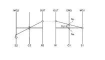
- FIG. 2 is an alignment chart according to the EV traveling mode of the embodiment.
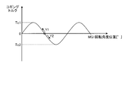
- FIG. 3 is a diagram illustrating an example of cogging torque.
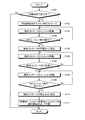
- FIG. 4 is a flowchart according to the learning control of the embodiment.
- FIG. 5 is a time chart according to the learning control of the embodiment.
- FIG. 1 is a skeleton diagram of a vehicle according to an embodiment of the present invention
- FIG. 2 is a collinear diagram according to the EV traveling mode of the embodiment
- FIG. 3 is a diagram illustrating an example of cogging torque
- FIG. 5 is a time chart according to the learning control of the embodiment.
- the vehicle 100 is a hybrid vehicle having an engine 1, a first rotating machine MG1, and a second rotating machine MG2.
- Vehicle 100 may be a plug-in hybrid (PHV) vehicle that can be charged by an external power source.
- the vehicle control device 1-1 according to the present embodiment includes a first rotating machine MG1, a clutch CL1, a rotation angle position detection device 5, and an ECU 50.
- the vehicle control device 1-1 may further include an engine 1, a second rotating machine MG2, a first planetary gear mechanism 10, and the like.
- the drive device of the vehicle 100 according to the present embodiment is applicable to an FF (front engine front wheel drive) vehicle, an RR (rear engine rear wheel drive) vehicle, or the like.
- the drive device is mounted on the vehicle 100 so that the axial direction of the input shaft 2 is in the vehicle width direction.
- the output shaft 1a is connected to the input shaft 2 via the clutch CL1.
- the clutch CL1 can transmit torque to the first rotating machine MG1 by being engaged.
- the clutch CL1 is a friction-joint type clutch device, for example, a wet multi-plate type.
- the clutch CL1 of the present embodiment is configured to be able to control a clutch stroke that is a stroke amount in the joining direction.
- the clutch CL1 includes, for example, a stroke sensor that detects a clutch stroke.
- the clutch stroke of the clutch CL1 of this embodiment is controlled by adjusting the supplied hydraulic pressure.
- the supply pressure of the clutch CL1 is feedback-controlled so that the detected clutch stroke is the target clutch stroke.
- the input shaft 2 is an input shaft of the power transmission unit, is coaxial with the output shaft 1a, and is disposed on an extension line of the output shaft 1a.
- the input shaft 2 is connected to the first carrier 14 of the first planetary gear mechanism 10 and rotates integrally with the first carrier 14.
- the first planetary gear mechanism 10 is an example of a differential mechanism in which the engine 1, the first rotating machine MG1, and the second rotating machine MG2 are connected to different rotating elements.
- the first planetary gear mechanism 10 is a single pinion type and includes a first sun gear 11, a first pinion gear 12, a first ring gear 13, and a first carrier 14.
- the first ring gear 13 is coaxial with the first sun gear 11 and is disposed on the radially outer side of the first sun gear 11.
- the first pinion gear 12 is disposed between the first sun gear 11 and the first ring gear 13 and meshes with the first sun gear 11 and the first ring gear 13, respectively.
- the first pinion gear 12 is rotatably supported by the first carrier 14.
- the first carrier 14 is connected to the input shaft 2 and rotates integrally with the input shaft 2. Therefore, the first pinion gear 12 can rotate (revolve) together with the input shaft 2 around the central axis of the input shaft 2 and is supported by the first carrier 14 and rotated around the central axis of the first pinion gear 12 ( Rotation) is possible.
- the first sun gear 11 is connected to the rotary shaft 33 of the first rotary machine MG1, and rotates integrally with the rotor 4 of the first rotary machine MG1.
- the first rotating machine MG1 is disposed on the engine 1 side with respect to the first planetary gear mechanism 10.
- the second planetary gear mechanism 20 is coaxial with the first planetary gear mechanism 10 and is disposed on the side opposite to the engine 1 side.
- the second planetary gear mechanism 20 is disposed adjacent to the first planetary gear mechanism 10 and constitutes a composite planetary together with the first planetary gear mechanism 10.
- the second planetary gear mechanism 20 has a function as a speed reduction planetary that decelerates and outputs the rotation of the second rotary machine MG2.
- the second planetary gear mechanism 20 is a single pinion type and includes a second sun gear 21, a second pinion gear 22, a second ring gear 23, and a second carrier 24.
- the second ring gear 23 is coaxial with the second sun gear 21 and is disposed on the radially outer side of the second sun gear 21.
- the second pinion gear 22 is disposed between the second sun gear 21 and the second ring gear 23 and meshes with the second sun gear 21 and the second ring gear 23, respectively.
- the second pinion gear 22 is rotatably supported by the second carrier 24.
- the second carrier 24 is fixed to the vehicle body side so as not to rotate.
- the second pinion gear 22 is supported by the second carrier 24 and can rotate (spin) around the central axis of the second pinion gear 22.
- the second sun gear 21 is connected to the rotary shaft 34 of the second rotary machine MG2 and rotates integrally with the rotor 7 of the second rotary machine MG2.
- the second ring gear 23 is connected to the first ring gear 13 and rotates integrally with the first ring gear 13.
- Counter drive gears 25 are provided on the outer peripheral surfaces of the first ring gear 13 and the second ring gear 23.
- the counter drive gear 25 is an output gear provided on the output shafts of the first planetary gear mechanism 10 and the second planetary gear mechanism 20.
- the counter drive gear 25 meshes with the counter driven gear 26.
- the counter driven gear 26 is connected to a drive pinion gear 28 via a counter shaft 27.
- the drive pinion gear 28 meshes with the diffring gear 29 of the differential device 30.
- the differential device 30 is connected to drive wheels 32 via left and right drive shafts 31.
- the first rotating machine MG1 and the second rotating machine MG2 each have a function as a motor (electric motor) and a function as a generator.
- the first rotating machine MG1 includes a stator 3 fixed to the vehicle body side and a rotor 4 that is rotatably supported.
- the second rotating machine MG2 has a stator 6 fixed to the vehicle body side and a rotor 7 supported rotatably.
- the first rotary machine MG1 and the second rotary machine MG2 are connected to a battery via an inverter.
- the first rotating machine MG1 and the second rotating machine MG2 can convert the electric power supplied from the battery into mechanical power and output it, and are driven by the input power to convert the mechanical power into electric power. Can be converted.
- the electric power generated by the rotating machines MG1 and MG2 can be stored in the battery.
- an AC synchronous motor generator can be used as the first rotating machine MG1 and the second rotating machine MG2, for example, an AC synchronous motor generator can be used
- the rotation angle position detection device 5 detects the rotation angle position of the rotor 4 of the first rotating machine MG1 (hereinafter also referred to as “MG1 rotation angle position”).
- the rotation angle position detection device 5 of this embodiment is a resolver and can detect the MG1 rotation angle position with high accuracy.
- An oil pump OP is disposed at the end of the input shaft 2 opposite to the engine 1 side. The oil pump OP is driven by the rotation of the input shaft 2 and supplies lubricating oil to each part of the vehicle 100.
- the ECU 50 is an electronic control unit having a computer.
- the ECU 50 is electrically connected to the engine 1, the first rotating machine MG1, and the second rotating machine MG2, and can control the engine 1, the first rotating machine MG1, and the second rotating machine MG2, respectively.
- the ECU 50 can execute various controls such as injection control, ignition control, and intake control of the engine 1. Further, the ECU 50 can control the output torque of the first rotating machine MG1 (hereinafter referred to as “MG1 torque”).
- MG1 torque the output torque of the first rotating machine MG1
- the input / output current (including the power generation amount) for the first rotating machine MG1 is adjusted according to the torque command value for the first rotating machine MG1, and the MG1 torque is controlled.
- the ECU 50 can control the output torque of the second rotary machine MG2 (hereinafter referred to as “MG2 torque”).
- MG2 torque the output torque of the second rotary machine MG2
- the input / output current (including the power generation amount) for the second rotary machine MG2 is adjusted according to the torque command value for the second rotary machine MG2, and the MG2 torque is controlled.
- the ECU50 controls clutch CL1.
- the ECU 50 outputs a clutch stroke command value to the clutch CL1.
- a hydraulic control device (not shown) of the clutch CL1 adjusts the joint hydraulic pressure of the clutch CL1 using the clutch stroke command value as a target clutch stroke.
- the ECU 50 is electrically connected to the rotation angle position detection device 5, and acquires the rotation angle position of the rotor 4 of the first rotating machine MG1 based on the detection result of the rotation angle position detection device 5.
- the vehicle 100 can selectively execute the EV traveling mode or the HV traveling mode.
- the EV travel mode is a travel mode in which the second rotary machine MG2 is used as a power source.
- the S1 axis indicates the rotation speed of the first sun gear 11 and the first rotating machine MG1 (hereinafter referred to as “MG1 rotation speed”)
- the C1 axis indicates the first carrier 14 and the engine 1.
- the rotation speed is indicated, and the R1 axis indicates the rotation speed of the first ring gear 13.
- the square mark indicates the engine speed Ne
- the circle indicates the carrier speed Nc that is the speed of the first carrier 14.
- the S2 axis indicates the rotation speed of the second rotating machine MG2 (hereinafter referred to as “MG2 rotation speed”)
- the C2 axis indicates the rotation speed of the second carrier 24, and the R2 axis indicates the second rotation speed.
- the rotation speed of the ring gear 23 is shown. In this embodiment, since the 1st ring gear 13 and the 2nd ring gear 23 are connected, both rotation speed corresponds.
- the clutch CL1 is released during EV travel.
- the engine 1 is stopped and the carrier rotational speed Nc becomes a rotational speed corresponding to the vehicle speed.
- the second rotating machine MG2 outputs negative torque and rotates negatively, thereby outputting positive torque from the second ring gear 23 and causing the vehicle 100 to generate a driving force in the forward direction.
- the normal rotation is the rotation direction of the ring gears 13 and 23 when the vehicle 100 moves forward. Since the second carrier 24 is restricted in rotation, it functions as a reaction force receiver for the MG2 torque and transmits the MG2 torque to the second ring gear 23.
- the rotation of the first rotating machine MG1 is stopped during EV traveling.
- the first rotating machine MG1 is maintained in a state where the rotation is stopped by cogging torque, for example. Since the first rotating machine MG1 is stopped, dragging loss and the like of the first rotating machine MG1 are reduced.
- HV traveling mode is a traveling mode in which the engine 1 is used as a power source.
- the second rotary machine MG2 may be a power source.
- the clutch CL1 is engaged.
- the first rotary machine MG1 functions as a reaction force receiver for the engine torque.
- the first rotating machine MG1 functions as a reaction force receiver for engine torque by outputting MG1 torque, and outputs engine torque from the first ring gear 13.
- the first planetary gear mechanism 10 can function as a power split mechanism that distributes engine torque to the first rotating machine MG1 side and the output side.
- the engagement position of the clutch CL1 can be accurately grasped in the engagement / release control of the clutch CL1.
- the engagement position of the clutch CL1 is a clutch stroke at which the clutch CL1 starts to be engaged.
- the engagement position of the clutch CL1 is a clutch stroke in which the engagement elements of the clutch CL1 are engaged with each other when the clutch stroke of the clutch CL1 is increased and torque is transmitted.
- the clutch stroke is such that when the clutch stroke is reduced from the combined state, the coupling of the coupling elements is canceled and torque is not transmitted.
- the vehicle control device 1-1 of the present embodiment performs learning control of the joint position of the clutch CL1.
- learning control of the engagement position of the clutch CL1 is performed, for example, the engagement position is determined based on fluctuations in the MG1 rotation speed when the clutch CL1 is engaged or released while the first rotating machine MG1 is rotating. It is conceivable to detect. However, in such a learning method based on fluctuations in the rotational position, a loss due to rotation of the first rotary machine MG1 or the like occurs. Further, when learning is performed based on the rotation change, the learning accuracy may vary.
- the vehicle control device 1-1 determines the engagement position of the clutch CL1 based on a change in cogging torque when the clutch stroke of the clutch CL1 is changed when the first rotary machine MG1 is stopped. learn. Thereby, the joint position of the clutch CL1 can be learned without rotating the first rotating machine MG1. Therefore, generation
- the ECU 50 functions as a detection unit that detects a change in cogging torque of the first rotating machine MG1.
- the ECU 50 detects a change in cogging torque based on the detection result of the rotation angle position detection device 5.
- a method for detecting a change in cogging torque will be described with reference to FIG.
- the cogging torque changes in a sine wave shape according to the MG1 rotation angle position.
- the rotor 4 is stopped at a stable position (for example, a position where the cogging torque is 0 as an example) where the magnetic force in the positive rotation direction and the magnetic force in the negative rotation direction are balanced, for example, without the input / output current of the first rotating machine MG1.
- a stable position for example, a position where the cogging torque is 0 as an example
- the input torque from the outside is a torque between the positive extreme value Tc1 and the negative extreme value Tc2 of the cogging torque.
- the rotor 4 stops at the MG1 rotation angle position where the torque is balanced.
- the ECU 50 engages the clutch CL1 from the state where the first rotary machine MG1 is stopped.
- torque starts to be transmitted to the rotor 4 of the first rotating machine MG1, or the torque transmitted to the rotor 4 changes.
- the MG1 rotation angle position changes to the side where the cogging torque increases as indicated by the arrow Y1.
- the MG1 rotation angle position changes to the side where the cogging torque decreases as indicated by the arrow Y2. That is, the change in the MG1 rotation angle position indicates a change in the cogging torque of the first rotating machine MG1, and indicates a change in the input torque to the rotor 4.
- the ECU 50 detects the clutch engagement position based on the change in the cogging torque due to the change in the input torque to the rotor 4.
- the ECU 50 can learn the clutch stroke at which the MG1 rotation angle position starts to change when the clutch stroke is increased from the state in which the clutch CL1 is released as the engagement position of the clutch CL1. Further, the ECU 50 does not learn a clutch stroke in which the MG1 rotation angle position does not change as the clutch stroke is increased, as a joint position.
- the ECU 50 determines the clutch stroke in which the MG1 rotation angle position does not change when the clutch CL1 is engaged and the clutch stroke is decreased from the state in which the first rotating machine MG1 has stopped rotating due to the cogging torque. It can be learned as a joint position. In addition, the ECU 50 does not learn the clutch stroke in which the MG1 rotation angle position changes when the clutch stroke is decreased as the joining position.
- connection position can be detected with high accuracy based on the change in the detection value of the rotation angle position detection device 5.
- FIG. 4 and FIG. 5 the joining position learning control of this embodiment is demonstrated.
- the control flow shown in FIG. 4 is executed, for example, when it is required to learn the engagement position of the clutch CL1, and is repeatedly executed at predetermined intervals.
- step S101 the ECU 50 determines whether or not the vehicle is traveling in the disconnected state. For example, the ECU 50 makes an affirmative determination in step S101 when the vehicle travels with the clutch CL1 disengaged. In step S101, it is determined whether the joint position learning control of the clutch CL1 can be started. When executing the learning control of the joining position, the first rotating machine MG1 may be shut down and stopped by the cogging torque. For example, the ECU 50 makes an affirmative determination in step S101 during EV traveling, and learns the engagement position of the clutch CL1. As a result of the determination in step S101, if it is determined that the vehicle is traveling in the disconnected state (step S101-Y), the process proceeds to step S102, and if not (step S101-N), the control flow ends.
- step S102 the ECU 50 strokes the clutch CL1 up to the learning start point.
- the learning start point shown in FIG. 5 is appropriately set at a stroke before the joining start position. By starting the increase of the clutch stroke from the learning start point, the learning period can be made shorter than when the increase of the clutch stroke is started from zero.
- the ECU 50 outputs the clutch stroke st1 as the learning start point as a clutch stroke command value for the clutch CL1.
- step S103 the ECU 50 moves the clutch stroke from the current stroke by a stroke change amount ⁇ strk.
- the stroke change amount ⁇ strk is a positive clutch stroke, and is the minimum movement amount of the clutch stroke in this embodiment.
- the ECU 50 increases the clutch stroke command value by the stroke change amount ⁇ strk, and moves the coupling element of the clutch CL1 in the coupling direction.
- step S104 the ECU 50 determines whether or not the MG1 resolver angle has changed.
- the ECU 50 determines whether or not the MG1 rotation angle position detected by the rotation angle position detection device 5 has changed before and after the clutch stroke command value is changed in step S103.
- step S104-Y if it is determined that the MG1 resolver angle has changed (step S104-Y), the process proceeds to step S105. If not (step S104-N), the process proceeds to step S103, where the clutch stroke Is increased.
- step S105 the ECU 50 sets the current stroke to the learning point 1.
- the MG1 resolver angle starts to change at time t1, and the current stroke st4 at this time is set to the learning point 1.
- step S106 the ECU 50 moves the clutch stroke from the current stroke by a stroke change amount ⁇ strk.
- the ECU 50 increases the clutch stroke command value by the stroke change amount ⁇ strk to further move the coupling element of the clutch CL1 in the coupling direction.
- step S107 the ECU 50 determines whether or not a predetermined stroke has been reached.
- the predetermined stroke is a clutch stroke larger than the clutch stroke at the joining position, and is determined in advance. As shown in FIG. 5, the predetermined stroke st5 is larger than the learning point 1 (clutch stroke st4).
- the ECU 50 moves the coupling element of the clutch CL1 in the release direction to learn the coupling position.
- step S107 if it is determined that the predetermined stroke has been reached (step S107-Y), the process proceeds to step S108. If not (step S107-N), the process proceeds to step S106, and the clutch stroke is Will be increased.
- step S108 the ECU 50 moves the clutch stroke from the current stroke in the releasing direction by a stroke change amount ⁇ strk.
- the ECU 50 decreases the clutch stroke command value by the stroke change amount ⁇ strk and moves the coupling element of the clutch CL1 in the release direction.
- step S109 the ECU 50 determines whether or not the MG1 resolver angle has changed.
- the ECU 50 determines whether or not the MG1 rotation angle position detected by the rotation angle position detection device 5 has not changed before and after the clutch stroke command value is changed in step S108.
- step S109-Y if it is determined that the MG1 resolver angle has not changed (step S109-Y), the process proceeds to step S110. If not (step S109-N), the process proceeds to step S108, and the clutch stroke Is reduced.
- step S110 the ECU 50 sets the current stroke to the learning point 2.
- the change in the MG1 resolver angle is not detected at time t2, and the current stroke st2 at this time is set to the learning point 2.
- step S111 the ECU 50 learns the clutch stroke calculated by the following equation (1) as the engagement start point.
- (Learning point 1 ⁇ strk) in the above equation (1) is a clutch stroke at which the MG1 rotation angle position starts to change, and in the case of FIG. 5, is the clutch stroke st3.
- the (learning point 2 + ⁇ strk) in the above equation (1) is a clutch stroke at which the MG1 rotation angle position does not change, and in the case of FIG. 5, is the clutch stroke st3.
- the ECU 50 determines the clutch stroke (learning point 1- ⁇ strk) at which the MG1 rotation angle position starts to change while the clutch stroke is increasing, and the clutch stroke (learning point 2 + ⁇ strk) at which the MG1 rotation angle position does not change while the clutch stroke is decreasing. ) Is learned as the engagement position of the clutch CL1. Variation in learning can be reduced by using the average stroke as the joining position.
- the engagement position of the clutch CL1 can be learned without rotating the first rotary machine MG1, and loss due to the rotation of the first rotary machine MG1 or the like is generated. Can be suppressed. Further, the engagement position of the clutch CL1 can be learned with high accuracy.
- the ECU 50 may learn the clutch stroke (learning point 1- ⁇ strk) at which the MG1 rotation angle position starts to change as the joining position instead of learning the average stroke as the joining position. Further, the ECU 50 may learn the clutch stroke (the learning point 2 + ⁇ strk) at which the MG1 rotation angle position does not change as the joining position.
- the clutch stroke at which the MG1 rotation angle position starts to change may be the learning point 1 or another clutch stroke.
- the clutch stroke at which the MG1 rotation angle position starts to change is the MG1 rotation angle even if the clutch stroke immediately before the MG1 rotation angle position changes when the clutch stroke command value is increased by the stroke change amount ⁇ strk. It may be a clutch stroke immediately after the position is changed.
- the clutch stroke at which the MG1 rotation angle position does not change may be the learning point 2 or another clutch stroke. That is, the clutch stroke at which the MG1 rotation angle position does not change is the MG1 rotation even if the clutch stroke immediately before the MG1 rotation angle position does not change when the clutch stroke command value is decreased by the stroke change amount ⁇ strk. It may be a clutch stroke immediately after the angular position no longer changes.
- the learning control of the engagement position of the clutch CL1 is performed while the vehicle 100 is traveling. However, it is also possible to execute the learning control under other circumstances in which the differential rotation occurs in the clutch CL1. .
- the engagement position of the clutch CL1 can be learned while the vehicle 100 is stopped and the engine 1 is operating.
- the ECU 50 learns the joining position when the engine 1 is operating, the first rotating machine MG1 is stopped, and the clutch stroke is increased from the released state while the vehicle 100 is stopped. can do.
- the clutch stroke at which the MG1 rotation angle position starts to change may be learned as the engagement position of the clutch CL1.
- the ECU 50 learns the engagement position when the engine 1 is operating, the first rotating machine MG1 is stopped, and the clutch stroke is decreased from the state where the clutch CL1 is engaged while the vehicle 100 is stopped. can do. Similar to the above embodiment, the clutch stroke at which the MG1 rotation angle position does not change may be learned as the engagement position of the clutch CL1.
- the ECU 50 first detects the engagement position while engaging the clutch CL1, and then detects the engagement position while releasing the clutch CL1, but this is the reverse order.
- the joining position may be learned at.
- the stroke change amount ⁇ strk is the minimum movement amount of the clutch CL1, but is not limited to this.
- the stroke change amount ⁇ strk may be a clutch stroke larger than the minimum movement amount.
- the stroke change amount ⁇ strk may be several steps of the minimum movement amount.
- the stroke change amount ⁇ strk is such that the magnitude of the input torque of the first rotating machine MG1 is the maximum cogging torque (positive extreme value Tc1 or It is only necessary to be determined so as not to be greater than or equal to the value Tc2.
- the vehicle 100 to be applied is not limited to that exemplified in the embodiment.
- the vehicle control device 1-1 of the above embodiment can be applied to a vehicle equipped with an engine, a rotating machine, and a clutch that connects and disconnects the rotating machine, drive wheels, and engine.
- learning control of the clutch engagement position can be performed from a state where the clutch is released, the rotating machine is stopped, and the engine is operated.
- learning control of the clutch engagement position can be performed from a state where the engine is operated and the clutch is engaged so that the rotating machine stops at the cogging torque while the vehicle is stopped.
- the clutch engagement position can be learned in the same manner as in the second modification.
- the change in the cogging torque is detected based on the detection result of the rotation angle position detection device 5, but the change in the cogging torque may be detected by other methods.
- the rotation angle position detection device 5 is not limited to a resolver.
- the rotation angle position detection device 5 may be any device that can detect at least a change in the MG1 rotation angle position due to a change in cogging torque.
- the first rotating machine MG1 is connected to the first sun gear 11 and the clutch CL1 is connected to the first carrier 14, but this is not limitative.
- the first rotating machine MG1 and the clutch CL1 may be connected to different rotating elements in the first planetary gear mechanism 10 from the embodiment described above.
- the first rotating machine MG1 and the clutch CL1 may be connected without a differential mechanism such as the first planetary gear mechanism 10. That is, the clutch CL1 only needs to be arranged so that torque can be transmitted to the first rotating machine MG1 by being engaged.
- the engine 1, the first rotating machine MG1 and the second rotating machine MG2 may be connected to a rotating element different from the above embodiment in the first planetary gear mechanism 10.
Landscapes
- Engineering & Computer Science (AREA)
- Mechanical Engineering (AREA)
- Transportation (AREA)
- Chemical & Material Sciences (AREA)
- Combustion & Propulsion (AREA)
- General Engineering & Computer Science (AREA)
- Physics & Mathematics (AREA)
- Fluid Mechanics (AREA)
- Automation & Control Theory (AREA)
- Electric Propulsion And Braking For Vehicles (AREA)
- Hydraulic Clutches, Magnetic Clutches, Fluid Clutches, And Fluid Joints (AREA)
- Hybrid Electric Vehicles (AREA)
Abstract
Description
図1から図5を参照して、実施形態について説明する。本実施形態は、車両制御装置に関する。図1は、本発明の実施形態に係る車両のスケルトン図、図2は、実施形態のEV走行モードに係る共線図、図3は、コギングトルクの一例を示す図、図4は、実施形態の学習制御に係るフローチャート、図5は、実施形態の学習制御に係るタイムチャートである。
{(学習点1-Δstrk)+(学習点2+Δstrk)}/2…(1)
上記式(1)の(学習点1-Δstrk)は、MG1回転角度位置が変化し始めるクラッチストロークであり、図5の場合、クラッチストロークst3である。上記式(1)の(学習点2+Δstrk)は、MG1回転角度位置が変化しなくなるクラッチストロークであり、図5の場合、クラッチストロークst3である。
MG1回転角度位置が変化し始めるクラッチストロークは、学習点1とされてもよいし、その他のクラッチストロークとされてもよい。つまり、MG1回転角度位置が変化し始めるクラッチストロークは、クラッチストローク指令値をストローク変化量Δstrkずつ増加させていくときの、MG1回転角度位置が変化する直前のクラッチストロークであっても、MG1回転角度位置が変化した直後のクラッチストロークであってもよい。
上記実施形態では、車両100の走行中にクラッチCL1の継合位置の学習制御が実行されたが、クラッチCL1に差回転が生じている他の状況下で学習制御を実行することも可能である。例えば、車両100が停車し、エンジン1が運転している状況でクラッチCL1の継合位置を学習することができる。この場合、ECU50は、車両100の停車中に、エンジン1が運転し、第一回転機MG1が停止し、かつクラッチCL1が開放した状態からクラッチストロークを増加させていくときに継合位置を学習することができる。上記実施形態と同様に、MG1回転角度位置が変化し始めるクラッチストロークをクラッチCL1の継合位置として学習するようにすればよい。
上記実施形態では、ECU50は、始めにクラッチCL1を継合させていきながら継合位置を検出し、次にクラッチCL1を開放させていきながら継合位置を検出したが、これとは逆の順序で継合位置の学習がなされてもよい。
上記実施形態では、ストローク変化量ΔstrkがクラッチCL1の最小移動量であったが、これには限定されない。ストローク変化量Δstrkは、最小移動量よりも大きなクラッチストロークであってもよい。ストローク変化量Δstrkは、最小移動量の数ステップ分であってもよい。ストローク変化量Δstrkは、ストローク変化量Δstrkだけクラッチストロークを変化させる時のクラッチトルク容量の変化により、第一回転機MG1の入力トルクの大きさが最大コギングトルク(正の極値Tc1や負の極値Tc2の大きさ)以上とならないように定められていればよい。
適用対象の車両100は、実施形態で例示したものには限定されない。例えば、エンジンと、回転機と、回転機および駆動輪とエンジンとを断接するクラッチを搭載した車両に対しても上記実施形態の車両制御装置1-1は適用可能である。こうした車両では、停車中に、クラッチを開放し、回転機を停止し、かつエンジンを運転した状態から、クラッチの継合位置の学習制御を行うことができる。また、停車中に、エンジンを運転し、回転機がコギングトルクで停止するようにクラッチを継合した状態から、クラッチの継合位置の学習制御を行うことができる。例えば、上記第2変形例と同様にしてクラッチの継合位置を学習することができる。
上記実施形態では、回転角度位置検出装置5の検出結果に基づいてコギングトルクの変化が検出されたが、他の方法でコギングトルクの変化が検出されてもよい。また、回転角度位置検出装置5は、レゾルバには限定されない。回転角度位置検出装置5は、少なくともコギングトルクの変化によるMG1回転角度位置の変化を検出できるものであればよい。
上記実施形態では、第一回転機MG1が第一サンギア11に接続され、クラッチCL1が第一キャリア14に接続されていたが、これには限定されない。例えば、第一回転機MG1およびクラッチCL1は、それぞれ第一遊星歯車機構10における上記実施形態とは異なる回転要素に接続されていてもよい。また、第一回転機MG1とクラッチCL1とが第一遊星歯車機構10のような差動機構を介さずに接続されていてもよい。つまり、クラッチCL1は、継合することで第一回転機MG1に対してトルクを伝達できるように配置されているものであればよい。
1 エンジン
3 ステータ
4 ロータ
5 回転角度位置検出装置
32 駆動輪
33,34 回転軸
50 ECU
CL1 クラッチ
MG1 第一回転機
MG2 第二回転機
Δstrk ストローク変化量
Claims (7)
- 回転機と、
継合することで前記回転機にトルクを伝達するクラッチと、
前記回転機のコギングトルクの変化を検出する検出部と、
を備え、
前記回転機が停止している場合に前記クラッチのクラッチストロークを変化させたときの前記コギングトルクの変化に基づいて前記クラッチの継合位置を学習する
ことを特徴とする車両制御装置。 - 前記回転機の回転角度位置を検出する回転角度位置検出装置を備え、
前記検出部は、前記回転角度位置検出装置の検出結果に基づいて前記コギングトルクの変化を検出する
請求項1に記載の車両制御装置。 - 前記クラッチストロークの増加中に前記回転角度位置が変化し始める前記クラッチストロークを前記クラッチの継合位置として学習する
請求項2に記載の車両制御装置。 - 前記クラッチストロークの減少中に前記回転角度位置が変化しなくなる前記クラッチストロークを前記クラッチの継合位置として学習する
請求項2に記載の車両制御装置。 - 前記クラッチストロークの増加中に前記回転角度位置が変化し始める前記クラッチストロークと、前記クラッチストロークの減少中に前記回転角度位置が変化しなくなる前記クラッチストロークとの平均ストロークを前記クラッチの継合位置として学習する
請求項2に記載の車両制御装置。 - 機関と、
第一回転機と、
第二回転機と、
前記機関、前記第一回転機および前記第二回転機がそれぞれ異なる回転要素に接続された差動機構と、
を備え、
前記クラッチは、継合することで前記第一回転機にトルクを伝達し、
前記検出部は、前記第一回転機のコギングトルクの変化を検出し、
前記第一回転機が停止している場合に前記クラッチのクラッチストロークを変化させたときの前記コギングトルクの変化に基づいて前記クラッチの継合位置を学習し、
前記クラッチの継合位置の学習は、前記第二回転機を動力源として走行中、および前記機関を運転して停車中に実行可能である
請求項1から5のいずれか1項に記載の車両制御装置。 - 更に、機関を備え、
前記クラッチは、前記回転機および駆動輪と前記機関とを断接し、
前記機関を運転して停車中に、前記クラッチの継合位置を学習する
請求項1から5のいずれか1項に記載の車両制御装置。
Priority Applications (7)
| Application Number | Priority Date | Filing Date | Title |
|---|---|---|---|
| KR1020157030924A KR101682326B1 (ko) | 2013-04-30 | 2013-04-30 | 차량 제어 장치 |
| DE112013007010.3T DE112013007010B4 (de) | 2013-04-30 | 2013-04-30 | Steuervorrichtung für ein Fahrzeug |
| CN201380076039.5A CN105209308B (zh) | 2013-04-30 | 2013-04-30 | 车辆控制装置 |
| PCT/JP2013/062639 WO2014178118A1 (ja) | 2013-04-30 | 2013-04-30 | 車両制御装置 |
| BR112015027602-4A BR112015027602B1 (pt) | 2013-04-30 | 2013-04-30 | Dispositivo de controle para um veículo |
| US14/787,584 US10208815B2 (en) | 2013-04-30 | 2013-04-30 | Vehicle control device |
| JP2015514717A JP6028855B2 (ja) | 2013-04-30 | 2013-04-30 | 車両制御装置 |
Applications Claiming Priority (1)
| Application Number | Priority Date | Filing Date | Title |
|---|---|---|---|
| PCT/JP2013/062639 WO2014178118A1 (ja) | 2013-04-30 | 2013-04-30 | 車両制御装置 |
Publications (1)
| Publication Number | Publication Date |
|---|---|
| WO2014178118A1 true WO2014178118A1 (ja) | 2014-11-06 |
Family
ID=51843271
Family Applications (1)
| Application Number | Title | Priority Date | Filing Date |
|---|---|---|---|
| PCT/JP2013/062639 Ceased WO2014178118A1 (ja) | 2013-04-30 | 2013-04-30 | 車両制御装置 |
Country Status (7)
| Country | Link |
|---|---|
| US (1) | US10208815B2 (ja) |
| JP (1) | JP6028855B2 (ja) |
| KR (1) | KR101682326B1 (ja) |
| CN (1) | CN105209308B (ja) |
| BR (1) | BR112015027602B1 (ja) |
| DE (1) | DE112013007010B4 (ja) |
| WO (1) | WO2014178118A1 (ja) |
Cited By (6)
| Publication number | Priority date | Publication date | Assignee | Title |
|---|---|---|---|---|
| JP2016191389A (ja) * | 2015-03-30 | 2016-11-10 | 本田技研工業株式会社 | 車両の変速装置 |
| JP6028855B2 (ja) * | 2013-04-30 | 2016-11-24 | トヨタ自動車株式会社 | 車両制御装置 |
| CN106476609A (zh) * | 2015-08-31 | 2017-03-08 | 比亚迪股份有限公司 | 动力传动系统及具有其的车辆 |
| CN106476599A (zh) * | 2015-08-31 | 2017-03-08 | 比亚迪股份有限公司 | 动力传动系统及具有其的车辆 |
| US9933025B2 (en) | 2014-05-14 | 2018-04-03 | Toyota Jidosha Kabushiki Kaisha | Control system for clutch |
| CN108025738A (zh) * | 2015-09-25 | 2018-05-11 | 爱信精机株式会社 | 车辆用驱动装置 |
Families Citing this family (3)
| Publication number | Priority date | Publication date | Assignee | Title |
|---|---|---|---|---|
| DE102014211381A1 (de) * | 2014-06-13 | 2015-12-17 | Schaeffler Technologies AG & Co. KG | Verfahren und Vorrichtung zur Ermittlung eines Tastpunktes einer Hybridtrennkupplung eines Hybridfahrzeuges |
| US11384508B2 (en) * | 2019-02-12 | 2022-07-12 | Caterpillar Inc. | Automated machine impeller clutch |
| US11940022B2 (en) * | 2022-07-15 | 2024-03-26 | Rivian Ip Holdings, Llc | Integrated disconnect for drive unit |
Citations (4)
| Publication number | Priority date | Publication date | Assignee | Title |
|---|---|---|---|---|
| JP2009006781A (ja) * | 2007-06-27 | 2009-01-15 | Nissan Motor Co Ltd | 車両の制御装置 |
| JP2010144596A (ja) * | 2008-12-18 | 2010-07-01 | Toyota Motor Corp | 内燃機関の制御装置 |
| JP2011079453A (ja) * | 2009-10-08 | 2011-04-21 | Toyota Motor Corp | ハイブリッド車両の駆動装置 |
| JP2012121495A (ja) * | 2010-12-09 | 2012-06-28 | Toyota Motor Corp | クラッチの学習制御装置 |
Family Cites Families (14)
| Publication number | Priority date | Publication date | Assignee | Title |
|---|---|---|---|---|
| DE10140745A1 (de) | 2000-09-15 | 2002-05-02 | Luk Lamellen & Kupplungsbau | Einrichtung zum Betätigen von Kupplungen sowie Verfahren zum Betreiben einer Eiinrichtung zum Betätigen von Kupplungen |
| JP2002168273A (ja) | 2000-10-13 | 2002-06-14 | Luk Lamellen & Kupplungsbau Beteiligungs Kg | 自動車 |
| DE10157506A1 (de) | 2000-12-20 | 2002-09-26 | Luk Lamellen & Kupplungsbau | Kraftfahrzeug und Vefahren zum Betreiben eines Kraftfahrzeuges |
| US8738256B2 (en) * | 2008-07-01 | 2014-05-27 | Eaton Corporation | Automatic calibration of the torque transfer touch point in an electrically actuated clutch in a hybrid vehicle |
| JP5433198B2 (ja) * | 2008-10-16 | 2014-03-05 | 日立オートモティブシステムズ株式会社 | 回転電機及び電気自動車 |
| KR101000424B1 (ko) * | 2008-11-20 | 2010-12-13 | 기아자동차주식회사 | 하이브리드 차량의 클러치 학습 제어 방법 |
| DE102009053885B4 (de) | 2009-11-20 | 2015-10-29 | Getrag Getriebe- Und Zahnradfabrik Hermann Hagenmeyer Gmbh & Cie Kg | Verfahren zur Kisspointadaption |
| CN102859224B (zh) | 2010-04-26 | 2015-06-17 | 舍弗勒技术股份两合公司 | 用于适配汽车动力传动系中离合器的接触点的方法 |
| CN103354790B (zh) * | 2011-02-09 | 2016-04-06 | 铃木株式会社 | 混合动力车辆的驱动控制设备及混合动力车辆 |
| DE102011014236A1 (de) | 2011-03-17 | 2011-12-08 | Daimler Ag | Verfahren zur Steuerung und/oder Regelung einer Kupplung in einem Antriebsstrang eines Hybridfahrzeuges |
| US8475329B2 (en) | 2011-07-22 | 2013-07-02 | GM Global Technology Operations LLC | Simultaneous auto-start and asynchronous shift for a hybrid vehicle |
| KR101807009B1 (ko) * | 2012-06-05 | 2017-12-08 | 현대자동차 주식회사 | 친환경 자동차의 엔진 클러치 전달토크 학습장치 및 방법 |
| KR101371461B1 (ko) * | 2012-09-06 | 2014-03-10 | 기아자동차주식회사 | 하이브리드 차량의 엔진클러치의 토크전달 시작점 학습 제어 방법 및 시스템 |
| CN105209308B (zh) * | 2013-04-30 | 2017-07-18 | 丰田自动车株式会社 | 车辆控制装置 |
-
2013
- 2013-04-30 CN CN201380076039.5A patent/CN105209308B/zh not_active Expired - Fee Related
- 2013-04-30 DE DE112013007010.3T patent/DE112013007010B4/de not_active Expired - Fee Related
- 2013-04-30 JP JP2015514717A patent/JP6028855B2/ja not_active Expired - Fee Related
- 2013-04-30 BR BR112015027602-4A patent/BR112015027602B1/pt not_active IP Right Cessation
- 2013-04-30 WO PCT/JP2013/062639 patent/WO2014178118A1/ja not_active Ceased
- 2013-04-30 US US14/787,584 patent/US10208815B2/en not_active Expired - Fee Related
- 2013-04-30 KR KR1020157030924A patent/KR101682326B1/ko not_active Expired - Fee Related
Patent Citations (4)
| Publication number | Priority date | Publication date | Assignee | Title |
|---|---|---|---|---|
| JP2009006781A (ja) * | 2007-06-27 | 2009-01-15 | Nissan Motor Co Ltd | 車両の制御装置 |
| JP2010144596A (ja) * | 2008-12-18 | 2010-07-01 | Toyota Motor Corp | 内燃機関の制御装置 |
| JP2011079453A (ja) * | 2009-10-08 | 2011-04-21 | Toyota Motor Corp | ハイブリッド車両の駆動装置 |
| JP2012121495A (ja) * | 2010-12-09 | 2012-06-28 | Toyota Motor Corp | クラッチの学習制御装置 |
Cited By (7)
| Publication number | Priority date | Publication date | Assignee | Title |
|---|---|---|---|---|
| JP6028855B2 (ja) * | 2013-04-30 | 2016-11-24 | トヨタ自動車株式会社 | 車両制御装置 |
| US9933025B2 (en) | 2014-05-14 | 2018-04-03 | Toyota Jidosha Kabushiki Kaisha | Control system for clutch |
| JP2016191389A (ja) * | 2015-03-30 | 2016-11-10 | 本田技研工業株式会社 | 車両の変速装置 |
| CN106476609A (zh) * | 2015-08-31 | 2017-03-08 | 比亚迪股份有限公司 | 动力传动系统及具有其的车辆 |
| CN106476599A (zh) * | 2015-08-31 | 2017-03-08 | 比亚迪股份有限公司 | 动力传动系统及具有其的车辆 |
| CN106476609B (zh) * | 2015-08-31 | 2019-03-29 | 比亚迪股份有限公司 | 动力传动系统及具有其的车辆 |
| CN108025738A (zh) * | 2015-09-25 | 2018-05-11 | 爱信精机株式会社 | 车辆用驱动装置 |
Also Published As
| Publication number | Publication date |
|---|---|
| KR20150138292A (ko) | 2015-12-09 |
| US10208815B2 (en) | 2019-02-19 |
| DE112013007010B4 (de) | 2023-06-15 |
| JPWO2014178118A1 (ja) | 2017-02-23 |
| CN105209308B (zh) | 2017-07-18 |
| BR112015027602A2 (pt) | 2017-07-25 |
| BR112015027602B1 (pt) | 2021-11-03 |
| CN105209308A (zh) | 2015-12-30 |
| KR101682326B1 (ko) | 2016-12-05 |
| JP6028855B2 (ja) | 2016-11-24 |
| US20160076606A1 (en) | 2016-03-17 |
| DE112013007010T5 (de) | 2016-01-21 |
Similar Documents
| Publication | Publication Date | Title |
|---|---|---|
| JP6028855B2 (ja) | 車両制御装置 | |
| CN102245453A (zh) | 动力传递控制装置 | |
| WO2018037627A1 (ja) | 動力装置 | |
| US10259308B2 (en) | Axle assembly for hybrid electric vehicle | |
| JP4029875B2 (ja) | 車両の制御装置 | |
| JPWO2013186924A1 (ja) | ハイブリッド車両用駆動装置 | |
| JP2006038136A (ja) | 駆動装置 | |
| JP2015024793A (ja) | ハイブリッド車両用駆動装置 | |
| WO2013145091A1 (ja) | ハイブリッド車両の駆動制御装置 | |
| US20160001764A1 (en) | Vehicle drive device | |
| US10435013B2 (en) | Hybrid vehicle drive system | |
| CN104908740A (zh) | 混合动力车辆用驱动装置的控制装置 | |
| JP5950036B2 (ja) | ハイブリッド車両用駆動装置 | |
| CN111683832A (zh) | 驱动装置以及车辆 | |
| JP4566230B2 (ja) | 駆動装置 | |
| US11300164B2 (en) | Control device for engagement mechanism | |
| JP2013199211A (ja) | ハイブリッド車両の制御装置 | |
| US9776627B2 (en) | Hybrid vehicle driving device | |
| CN113891814B (zh) | 一种混合动力系统的控制方法及系统 | |
| JP2015077847A (ja) | ハイブリッド車両用駆動装置 | |
| US20240083238A1 (en) | Vehicle drive device | |
| US20150375737A1 (en) | Vehicle drive device | |
| JP2015024794A (ja) | ハイブリッド車両用駆動装置 | |
| JP6048256B2 (ja) | ハイブリッド車両用駆動装置 | |
| JP2015110395A (ja) | ハイブリッド車両の制御装置 |
Legal Events
| Date | Code | Title | Description |
|---|---|---|---|
| 121 | Ep: the epo has been informed by wipo that ep was designated in this application |
Ref document number: 13883427 Country of ref document: EP Kind code of ref document: A1 |
|
| ENP | Entry into the national phase |
Ref document number: 2015514717 Country of ref document: JP Kind code of ref document: A |
|
| ENP | Entry into the national phase |
Ref document number: 20157030924 Country of ref document: KR Kind code of ref document: A |
|
| WWE | Wipo information: entry into national phase |
Ref document number: 14787584 Country of ref document: US |
|
| WWE | Wipo information: entry into national phase |
Ref document number: 1120130070103 Country of ref document: DE Ref document number: 112013007010 Country of ref document: DE |
|
| REG | Reference to national code |
Ref country code: BR Ref legal event code: B01A Ref document number: 112015027602 Country of ref document: BR |
|
| 122 | Ep: pct application non-entry in european phase |
Ref document number: 13883427 Country of ref document: EP Kind code of ref document: A1 |
|
| ENP | Entry into the national phase |
Ref document number: 112015027602 Country of ref document: BR Kind code of ref document: A2 Effective date: 20151030 |