WO2014175281A1 - 繊維強化多孔質中空糸膜の製造方法 - Google Patents
繊維強化多孔質中空糸膜の製造方法 Download PDFInfo
- Publication number
- WO2014175281A1 WO2014175281A1 PCT/JP2014/061325 JP2014061325W WO2014175281A1 WO 2014175281 A1 WO2014175281 A1 WO 2014175281A1 JP 2014061325 W JP2014061325 W JP 2014061325W WO 2014175281 A1 WO2014175281 A1 WO 2014175281A1
- Authority
- WO
- WIPO (PCT)
- Prior art keywords
- nozzle
- hollow fiber
- fiber membrane
- spinning
- membrane
- Prior art date
- Legal status (The legal status is an assumption and is not a legal conclusion. Google has not performed a legal analysis and makes no representation as to the accuracy of the status listed.)
- Ceased
Links
Images

Classifications
-
- B—PERFORMING OPERATIONS; TRANSPORTING
- B01—PHYSICAL OR CHEMICAL PROCESSES OR APPARATUS IN GENERAL
- B01D—SEPARATION
- B01D69/00—Semi-permeable membranes for separation processes or apparatus characterised by their form, structure or properties; Manufacturing processes specially adapted therefor
- B01D69/08—Hollow fibre membranes
-
- B—PERFORMING OPERATIONS; TRANSPORTING
- B01—PHYSICAL OR CHEMICAL PROCESSES OR APPARATUS IN GENERAL
- B01D—SEPARATION
- B01D69/00—Semi-permeable membranes for separation processes or apparatus characterised by their form, structure or properties; Manufacturing processes specially adapted therefor
- B01D69/08—Hollow fibre membranes
- B01D69/087—Details relating to the spinning process
-
- B—PERFORMING OPERATIONS; TRANSPORTING
- B01—PHYSICAL OR CHEMICAL PROCESSES OR APPARATUS IN GENERAL
- B01D—SEPARATION
- B01D71/00—Semi-permeable membranes for separation processes or apparatus characterised by the material; Manufacturing processes specially adapted therefor
- B01D71/06—Organic material
- B01D71/58—Other polymers having nitrogen in the main chain, with or without oxygen or carbon only
- B01D71/62—Polycondensates having nitrogen-containing heterocyclic rings in the main chain
- B01D71/64—Polyimides; Polyamide-imides; Polyester-imides; Polyamide acids or similar polyimide precursors
- B01D71/643—Polyether-imides
-
- D—TEXTILES; PAPER
- D01—NATURAL OR MAN-MADE THREADS OR FIBRES; SPINNING
- D01D—MECHANICAL METHODS OR APPARATUS IN THE MANUFACTURE OF ARTIFICIAL FILAMENTS, THREADS, FIBRES, BRISTLES OR RIBBONS
- D01D5/00—Formation of filaments, threads, or the like
- D01D5/24—Formation of filaments, threads, or the like with a hollow structure; Spinnerette packs therefor
-
- D—TEXTILES; PAPER
- D01—NATURAL OR MAN-MADE THREADS OR FIBRES; SPINNING
- D01D—MECHANICAL METHODS OR APPARATUS IN THE MANUFACTURE OF ARTIFICIAL FILAMENTS, THREADS, FIBRES, BRISTLES OR RIBBONS
- D01D5/00—Formation of filaments, threads, or the like
- D01D5/28—Formation of filaments, threads, or the like while mixing different spinning solutions or melts during the spinning operation; Spinnerette packs therefor
- D01D5/30—Conjugate filaments; Spinnerette packs therefor
- D01D5/34—Core-skin structure; Spinnerette packs therefor
-
- D—TEXTILES; PAPER
- D01—NATURAL OR MAN-MADE THREADS OR FIBRES; SPINNING
- D01F—CHEMICAL FEATURES IN THE MANUFACTURE OF ARTIFICIAL FILAMENTS, THREADS, FIBRES, BRISTLES OR RIBBONS; APPARATUS SPECIALLY ADAPTED FOR THE MANUFACTURE OF CARBON FILAMENTS
- D01F1/00—General methods for the manufacture of artificial filaments or the like
- D01F1/02—Addition of substances to the spinning solution or to the melt
- D01F1/10—Other agents for modifying properties
-
- B—PERFORMING OPERATIONS; TRANSPORTING
- B01—PHYSICAL OR CHEMICAL PROCESSES OR APPARATUS IN GENERAL
- B01D—SEPARATION
- B01D2325/00—Details relating to properties of membranes
- B01D2325/24—Mechanical properties, e.g. strength
-
- B—PERFORMING OPERATIONS; TRANSPORTING
- B01—PHYSICAL OR CHEMICAL PROCESSES OR APPARATUS IN GENERAL
- B01D—SEPARATION
- B01D2325/00—Details relating to properties of membranes
- B01D2325/40—Fibre reinforced membranes
Definitions
- the present invention relates to a method for producing a fiber-reinforced porous hollow fiber membrane. More specifically, the present invention relates to a method for producing a fiber-reinforced porous hollow fiber membrane having excellent mechanical strength.
- Porous hollow fiber membranes are used in various fields such as water purification treatment by membrane filtration, wastewater treatment, dehumidification or humidification.
- the PVDF membrane prepared by the thermally induced phase separation method has a strength of about 8 to 22 MPa, and among them, many are about 11 MPa in practical use. Compared with a membrane prepared by a non-solvent induced phase separation method, it does not necessarily have sufficient strength. In addition, the thermally induced phase separation method has a complicated process and requires cleaning with a large number of solvents, so that it is difficult to say that it is expensive and environmentally friendly.
- a membrane module membrane area of about 10 to 100 m 2
- a structure in which polysulfone, PVDF, etc., prepared using a non-solvent-induced phase separation method are fixed in a resin case with an adhesive is also used for wastewater treatment and water purification treatment. Many are used.
- Such a membrane module is supplied with water in an amount of several tens of liters to several hundreds of liters per minute. At that time, since the chemical cleaning or peristaltic cleaning for the purpose of recovering the flow rate is periodically performed, the hollow fiber membrane may be broken during use or cleaning.
- the method of dehumidifying or humidifying by the hollow fiber membrane method has many advantages such as not requiring maintenance but not requiring a power source for driving.
- a dehumidifying film or humidifying film a film-forming resin material such as polyimide, polysulfone, or polyphenylsulfone is used (for example, Patent Document 3).
- dehumidifying membranes using these materials are used in many industrial fields, they are porous, so the absolute strength of the membrane is weak, and depending on the application, a large amount of gas is used. Sometimes the hollow fiber membrane may break.
- a porous membrane in which reinforcing fibers are buried in a hollow fiber membrane has been proposed as a means for preventing the hollow fiber membrane from being broken and improving the mechanical strength (Patent Document 4).
- the reinforcing fiber is buried in the hollow fiber membrane and the reinforcing fiber is extruded together with the spinning stock solution from the outer nozzle of the double annular nozzle to produce a porous hollow fiber membrane, the spinning discharged from the nozzle
- the reinforcing fibers In the process of solidifying the stock solution into a membrane, there is a tendency for the reinforcing fibers to move outside the hollow fiber membrane, resulting in a portion that is not partially buried in the hollow fiber membrane and insufficiently reinforced, resulting in increased strength. Variations may occur and thread breakage may occur during use or cleaning.
- An object of the present invention is a porous hollow fiber membrane in which reinforcing fibers are completely buried in a hollow fiber membrane, and the fiber reinforced porous material has improved mechanical strength without impairing the original function of the porous hollow fiber membrane. Is to provide a method for producing a hollow fiber membrane.
- An object of the present invention is to provide a core liquid for the inner nozzle of the triple annular nozzle that constitutes a triple ring in the order of the inner nozzle, the middle nozzle, and the outer nozzle, the reinforcing fiber and the spinning dope for the outer nozzle, and the outer
- This is achieved by a method of producing a fiber-reinforced porous hollow fiber membrane by introducing a spinning solution into a nozzle and performing wet spinning or dry wet spinning.
- the reinforcing fibers discharged together with the spinning dope move to the outside of the hollow fiber membrane, and the spinning dope discharged from the outer nozzle coagulates to form a membrane.
- the reinforcing fiber is not partially buried in the hollow fiber membrane, and there is a case where the reinforcement is insufficient, but in the method of the present invention, the reinforcement pushed out from the middle nozzle using the triple annular nozzle Since the spinning solution is discharged from the outer nozzle further to the outside of the fiber, the hollow fiber membrane can be manufactured in a state where the reinforcing fiber is completely embedded inside the porous hollow fiber membrane, and the high strength hollow fiber There is an effect that a film can be obtained.
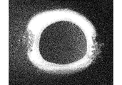
- FIG. 3 is an enlarged cross-sectional photograph of a reinforcing fiber-embedded porous hollow fiber membrane obtained in Example 1.
- FIG. 4 is an enlarged cross-sectional photograph of a reinforcing fiber-embedded porous hollow fiber membrane obtained in Comparative Example 4.
- the triple annular nozzle a conventionally known one is used, that is, a triple ring in the order of an inner nozzle, a middle nozzle and an outer nozzle having a diameter corresponding to a desired hollow fiber membrane size. If there is no particular limitation, it can be used. Permeation performance is achieved by placing reinforcing fibers at a position that does not exceed 90% of the thickness of the hollow fiber membrane as viewed from the surface of the hollow fiber membrane that is not the functional layer (workpiece contact side) of the porous hollow fiber membrane. Since the mechanical properties can be further improved while keeping the separation performance high, preferably a triple annular nozzle having an inner diameter, an inner nozzle having an outer diameter, an inner nozzle, and an outer nozzle capable of spinning such a hollow fiber membrane is provided. Selected.
- the fiber-reinforced porous hollow fiber membrane performs wet spinning or dry-wet spinning by introducing the core liquid into the inner nozzle of the triple annular nozzle, the reinforcing fiber and the spinning stock solution into the inner nozzle, and the spinning stock solution into the outer nozzle. It is manufactured by.
- a non-solvent of a film-forming resin for example, water, an aqueous polyvinyl pyrrolidone solution or the like is used.
- a polymer of the spinning dope any known hollow fiber membrane-forming material (polymer) can be used.
- cellulose-based materials such as cellulose acetate, cellulose propionate, cellulose butyrate, regenerated cellulose or a mixture thereof
- polysulfone-based materials examples thereof include hydrophobic polymers such as resins, polyethersulfone resins, polyvinylidene fluoride resins, polyacrylonitrile resins, polyimide resins, polyaramid resins, polypropylene resins, and polyethylene resins.
- an aprotic polar solvent such as alcohol, dimethylformamide, diethylformamide, dimethylacetamide, diethylacetamide, dimethylsulfoxide, N-methyl-2-pyrrolidone is preferably used.
- the spinning dope is introduced into both the inner nozzle and the outer nozzle, but the spinning dope used may be the same or different.
- the reinforcing fiber introduced into the middle nozzle together with the spinning dope can be used without particular limitation as long as it is a fiber material used as a conventionally used reinforcing material.
- a fiber material used as a conventionally used reinforcing material For example, monofilament, multifilament, spun yarn, etc.
- natural or synthetic materials such as polypropylene, polyethylene, fluororesin, polyethylene terephthalate, polybutylene terephthalate, polyacrylonitrile, polyphenylene sulfide, vinyl chloride, various celluloses, polylactic acid, polyvinyl alcohol, polyamide, polyimide, aramid, etc. Examples thereof include at least one of fiber, metal fiber such as stainless steel and copper, glass fiber, and carbon fiber, and polyethylene terephthalate fiber is preferably used.
- Such reinforcing fibers are introduced into the middle nozzle together with the spinning dope.
- Reinforcement fiber introduction into the middle nozzle is performed with the spinning solution from the location where the spinning solution is supplied, or a triple tube nozzle is equipped with a reinforcement fiber introduction pipe so that the reinforcement fiber can be introduced into the middle nozzle. Any method can be used as long as the reinforcing fiber can be introduced into the middle nozzle, such as a method using the above.
- the introduction of the reinforcing fiber is preferably performed along the outer peripheral surface of the inner nozzle. This is because the reinforcing fiber in the spinning dope is pushed out to the outer peripheral side of the membrane in the process in which the spinning dope discharged from the nozzle comes into contact with the core solution and the non-solvent of the core solution and the solvent of the spinning dope are changed into a film.
- the purpose is to suppress exposure of the reinforcing fiber to the outer periphery of the membrane.
- the reinforcing fibers are used evenly dispersed in the intermediate nozzle, but a plurality of reinforcing fibers may be inserted partially, for example, at a part of the intermediate nozzle or at a symmetrical position (see FIG. 1).
- the core liquid discharged from each nozzle and the spinning liquid may be discharged at the same pressure, but are preferably introduced to the outer nozzle to prevent the reinforcing fibers from being exposed outside the hollow fiber membrane.
- the extrusion pressure for the spinning dope is set higher than the extrusion pressure for the spinning dope introduced into the middle nozzle.
- the porous hollow fiber membrane is produced by coagulating, washing, and drying a porous hollow fiber membrane spun by wet spinning or dry wet spinning using a coagulating liquid.
- Example 1 Inner nozzle from inner nozzle than inner nozzle of triple tubular nozzle consisting of inner nozzle with inner diameter of 0.5mm, outer diameter of 0.7mm, outer nozzle with inner diameter of 2mm and inner diameter of 1mm, outer diameter of 1.125mm sandwiched between them While flowing out the water as the liquid, two polyethylene terephthalate multifilaments (yarn fineness 110 dtex / 24 filament; breaking strength 6N) as the reinforcing fiber and the spinning stock solution were fed to the feed rate of the spinning stock solution.
- the stock solution for spinning 20% by weight of polyphenylsulfone, 65% by weight of dimethylformamide, and 15% by weight of polyvinyl pyrrolidone are used. This was carried out using a pipe equipped with a reinforcing fiber introduction pipe in a state where the reinforcing fiber could be introduced into the middle nozzle. Further, the extrusion pressure of the spinning dope in the outer nozzle was 0.4 MPa, and the extrusion pressure of the spinning dope in the middle nozzle was 0.4 MPa.
- Reinforcing fiber embedded hollow fiber membrane material is subjected to high-pressure sterilization treatment at 121 ° C for 1 hour, and then placed in a constant temperature bath at a chamber temperature of 40 ° C for drying treatment, thereby reinforcing fiber embedded porous polyphenylsulfone A hollow fiber membrane was obtained.
- An enlarged cross-sectional photograph ( ⁇ 175) of the obtained reinforcing fiber-embedded porous hollow fiber membrane is shown in FIG. 1, and it was confirmed that the reinforcing fiber was completely buried in the hollow fiber membrane film thickness.
- the obtained porous polyphenylsulfone hollow fiber membrane has an outer diameter of 1000 ⁇ m, an inner diameter of 500 ⁇ m, a water vapor transmission rate at 25 ° C. of 0.28 g / cm 2 / min / MPa, and a pure water transmission rate of 0 ml / cm 2 / hour. / MPa, the air permeation rate was 0 ml / cm 2 / min / MPa. Further, a tensile test was conducted at a distance between marked lines of 50 mm and a test speed of 20 mm per minute, and the fracture stress was calculated to be 58 MPa.
- Example 2 In Example 1, a spinning stock solution prepared by using the same amount (20% by weight) of polysulfone instead of polyphenylsulfone was used.
- the obtained porous polysulfone hollow fiber membrane has an outer diameter of 1000 ⁇ m, an inner diameter of 500 ⁇ m, a water vapor transmission rate at 25 ° C. of 0.23 g / cm 2 / min / MPa, and a pure water transmission rate of 0 ml / cm 2 / hour / MPa.
- the air transmission rate was 0 ml / cm 2 / min / MPa.
- a tensile test was conducted at a distance between marked lines of 50 mm and a test speed of 20 mm per minute, and the breaking stress was calculated to be 57 MPa.
- Example 3 In Example 1, a spinning stock solution comprising 20% by weight of polyetherimide and 80% by weight of dimethylacetamide was used.
- the obtained porous polyetherimide hollow fiber membrane has an outer diameter of 1000 ⁇ m, an inner diameter of 500 ⁇ m, a water vapor transmission rate at 25 ° C. of 0.36 g / cm 2 / min / MPa, and a pure water transmission rate of 0 ml / cm 2 / hour. / MPa, the air permeation rate was 0 ml / cm 2 / min / MPa.
- a tensile test was performed at a distance between marked lines of 50 mm and a test speed of 20 mm per minute, and the breaking stress was calculated to be 57 MPa.
- Example 1 spinning is performed without using reinforcing fibers while water as core liquid is discharged from the inner nozzle of a double tubular nozzle comprising an inner nozzle having an inner diameter of 0.4 mm and an outer diameter of 0.6 mm and an outer nozzle having an inner diameter of 1.15 mm.
- the stock solution was discharged from the outer nozzle, passed through a free running space, solidified in water (coagulating liquid) at a water temperature of 50 ° C., and a hollow fiber membrane embedded with reinforcing fibers was obtained by dry and wet spinning.
- the porous polyphenylsulfone hollow fiber membrane obtained by drying this has an outer diameter of 1000 ⁇ m, an inner diameter of 700 ⁇ m, a water vapor transmission rate at 25 ° C.
- Comparative Example 2 In Comparative Example 1, when the spinning stock solution used in Example 2 was used as the spinning stock solution, the obtained porous polysulfone hollow fiber membrane had an outer diameter of 1000 ⁇ m and an inner diameter of 700 ⁇ m, and the water vapor transmission rate at 25 ° C. was 0.23. g / cm 2 / min / MPa, pure water permeation rate 0 ml / cm 2 / time / MPa, the air permeation rate was 0 ml / cm 2 / min / MPa. A tensile test was performed at a distance between marked lines of 50 mm and a test speed of 20 mm per minute, and the breaking stress was calculated to be 8.1 MPa.
- Comparative Example 3 In Comparative Example 1, when the spinning stock solution used in Example 3 was used as the spinning stock solution, the obtained porous polyetherimide hollow fiber membrane had an outer diameter of 1000 ⁇ m and an inner diameter of 700 ⁇ m, and the water vapor transmission rate at 25 ° C. was 0.36 g / cm 2 / min / MPa, the pure water permeation rate was 0 ml / cm 2 / hour / MPa, and the air permeation rate was 0 ml / cm 2 / min / MPa. A tensile test was performed at a distance between marked lines of 50 mm and a test speed of 20 mm per minute, and the breaking stress was calculated to be 8.0 MPa.
- Example 4 polyethylene terephthalate multifilament (yarn fineness 110 dtex / 24 filament) as a reinforcing fiber and spinning dope while water as core solution was allowed to flow out from the inner nozzle of a double tubular nozzle comprising an inner nozzle and an outer nozzle Was discharged from the outer nozzle and coagulated in water (coagulating liquid) having a water temperature of 50 ° C. to obtain a hollow fiber membrane embedded with reinforcing fibers by dry and wet spinning.
- An enlarged cross-sectional photograph ( ⁇ 175) of the reinforcing fiber-embedded porous polyetherimide hollow fiber membrane obtained by drying this is shown in FIG. 2, and a part of the reinforcing fiber is exposed to the outside of the hollow fiber. It was confirmed that
- This porous polyetherimide hollow fiber membrane has an outer diameter of 1000 ⁇ m, an inner diameter of 700 ⁇ m, a water vapor transmission rate at 25 ° C. of 0.36 g / cm 2 / min / MPa, and a pure water transmission rate of 0 ml / cm 2 / hour / MPa
- the air transmission rate was 0 ml / cm 2 / min / MPa.
- a tensile test was performed at a distance between marked lines of 50 mm and a test speed of 20 mm per minute, and the breaking stress was calculated. Depending on the location from 8.0 to 27.0 MPa, such as the strength without reinforcement to about half of the strength during full reinforcement. Unevenness was seen.
- the obtained fiber-reinforced porous hollow fiber membrane can suppress yarn breakage under high load and long-term use, so it can be used in various fields such as water purification treatment by membrane filtration, wastewater treatment, dehumidification or humidification. Can be used effectively.
Landscapes
- Chemical & Material Sciences (AREA)
- Chemical Kinetics & Catalysis (AREA)
- Engineering & Computer Science (AREA)
- Textile Engineering (AREA)
- Mechanical Engineering (AREA)
- Manufacturing & Machinery (AREA)
- General Chemical & Material Sciences (AREA)
- Separation Using Semi-Permeable Membranes (AREA)
- Spinning Methods And Devices For Manufacturing Artificial Fibers (AREA)
Abstract
内側ノズル、中側ノズルおよび外側ノズルの順に三重の環を構成している三重環状ノズルの内側ノズルに芯液を、中側ノズルに補強繊維および紡糸原液を、さらに外側ノズルに紡糸原液をそれぞれ導入して湿式紡糸または乾湿式紡糸を行うことにより繊維強化多孔質中空糸膜を製造する。この製造方法により、補強繊維を中空糸膜中に完全に埋没させた多孔質中空糸膜であって、多孔質中空糸膜本来の機能を損なうことなく機械的強度を向上せしめた繊維強化多孔質中空糸膜を得ることができる。
Description
本発明は、繊維強化多孔質中空糸膜の製造方法に関する。さらに詳しくは、機械的強度にすぐれた繊維強化多孔質中空糸膜の製造方法に関する。
多孔質中空糸膜は、膜ロ過による浄水処理、廃水処理、除湿あるいは加湿を行う際などさまざまな分野で用いられている。
膜ロ過による浄水処理や廃水処理は、これまでの凝集沈殿のロ過方式と比較し、運転の維持や管理が容易であり、処理水質も良好であることから、近年水処理分野で幅広く用いられている。例えば活性汚泥処理と膜分離処理を組み合わせたメンブレンリアクター法〔MBR〕の膜分離処理に用いられる膜としては、高強度、耐久性、耐薬品性が要求されることから、特許文献1~2に記載されている熱誘起相分離法によって調製されるポリフッ化ビニリデン〔PVDF〕膜が使用されることが多い。
しかしながら、熱誘起相分離法によって調製されるPVDF膜は、強度が8~22MPa程度であり、またこのうち実用されているものは11MPa程度のものが多いというように、ある程度の強度は示すものの、非溶媒誘起相分離法で調製された膜と比較して、必ずしも十分な強度を有しているものとはいえない。また、熱誘起相分離法は工程が複雑であり、多くの溶剤を用いた洗浄が必要であることから高コストで環境にやさしいものとはいい難いといった側面を有する。
一方、非溶媒誘起相分離法を用いて調製されるポリスルホンやPVDF等を樹脂ケース内に接着剤を用いて固定した構造の膜モジュール(膜面積約10~100m2)も廃水処理や浄水処理に多く使用されている。このような膜モジュールには毎分数10L~数100Lといった量の水が供給されて使用される。その際、定期的に流量回復を目的とした薬品洗浄や搖動洗浄などが施されることから、使用時あるいは洗浄時に中空糸膜が破断する場合がある。
また、中空糸膜方式で除湿あるいは加湿を行う方法は、メンテナンス不要であるばかりではなく、駆動に電源を必要とはしないなど多くの利点を有している。このような除湿膜あるいは加湿膜としては、ポリイミド、ポリスルホン、ポリフェニルスルホンといった膜形成性樹脂材料が用いられている(例えば特許文献3)。これらの材料を用いた除湿膜は、多くの産業分野で用いられているものの、多孔質であるために膜の絶対強度が弱く、用途によっては多量の気体を流して使用されるために、使用時に中空糸膜が破断するといったおそれがある。一方、加湿膜についても、近年では燃料電池スタックの隔膜の加湿に多く用いられているが、この場合にも例えば車載用途において4000NL/分程度の多量の空気が流れることから、その機械的強度との関係で中空糸膜切れといったおそれがある。
このような多孔質中空糸膜の中空糸膜切れを防止し、機械的強度を向上させる手段として補強繊維を中空糸膜中に埋没させた多孔質膜が提案されている(特許文献4)。ここで、補強繊維を中空糸膜中に埋没させるに当り、二重環状ノズルの外側ノズルより紡糸原液とともに補強繊維を押し出して多孔質中空糸膜を製造した場合には、ノズルから吐出された紡糸原液が凝固して膜になる過程において、補強繊維が中空糸膜の外側に移動する傾向がみられ、部分的に中空糸膜内に埋没されず補強が不十分な部位が生じることから強度にバラツキを生じ、使用時あるいは洗浄時に糸切れが発生するおそれもある。
本発明の目的は、補強繊維を中空糸膜中に完全に埋没させた多孔質中空糸膜であって、多孔質中空糸膜本来の機能を損なうことなく機械的強度を向上せしめた繊維強化多孔質中空糸膜の製造方法を提供することにある。
かかる本発明の目的は、内側ノズル、中側ノズルおよび外側ノズルの順に三重の環を構成している三重環状ノズルの内側ノズルに芯液を、中側ノズルに補強繊維および紡糸原液を、さらに外側ノズルに紡糸原液をそれぞれ導入して湿式紡糸または乾湿式紡糸を行い、繊維強化多孔質中空糸膜を製造する方法によって達成される。
二重環状ノズルを用いて紡糸した場合には、紡糸原液とともに吐出された補強繊維は中空糸膜状物の外側に移動してしまい、外側ノズルから吐出された紡糸原液が凝固して膜を形成する過程において、補強繊維が部分的に中空糸膜内に埋没されず補強が不十分な部位が生じる場合があるが、本発明方法では三重環状ノズルを用いて、中側ノズルより押し出された補強繊維の外側にさらに外側ノズルより紡糸原液が吐出されることから、多孔質中空糸膜の膜内部に補強繊維を完全に埋め込んだ状態で中空糸膜を製造することができ、高強度の中空糸膜を得ることができるといった効果を奏する。
三重環状ノズルとしては、従来から用いられている公知のもの、すなわち所望の中空糸膜サイズに応じた径を有する内側ノズル、中側ノズルおよび外側ノズルの順に三重の環を構成しているものであれば特に制限なく用いることができる。なお、補強繊維を多孔質中空糸膜の機能層(被処理物接触側)ではない側の中空糸膜表面からみて中空糸膜膜厚の90%を超えない位置に配置させることにより、透過性能、分離性能を高く保ちつつ力学的特性をさらに向上させることができることから、好ましくはかかる中空糸膜を紡糸し得る内径、外径を有する内側ノズル、中側ノズルおよび外側ノズルを有する三重環状ノズルが選択される。
繊維強化多孔質中空糸膜は、三重環状ノズルの内側ノズルに芯液を、中側ノズルに補強繊維および紡糸原液を、さらに外側ノズルに紡糸原液をそれぞれ導入して湿式紡糸または乾湿式紡糸を行うことにより製造される。
芯液としては、膜形成性樹脂の非溶媒、例えば水、ポリビニルピロリドン水溶液などが用いられる。紡糸原液のポリマーとしては、公知の中空糸膜形成材料(ポリマー)のいずれも用いることができ、例えば酢酸セルロース、プロピオン酸セルロース、酪酸セルロース、再生セルロースまたはこれらの混合物等のセルロース系材料、ポリスルホン系樹脂、ポリエーテルスルホン系樹脂、ポリフッ化ビニリデン系樹脂、ポリアクリロニトリル樹脂、ポリイミド樹脂、ポリアラミド樹脂、ポリプロピレン樹脂、ポリエチレン樹脂等の疎水性ポリマーが挙げられる。また、膜形成性樹脂の可溶性溶媒としてはアルコールやジメチルホルムアミド、ジエチルホルムアミド、ジメチルアセトアミド、ジエチルアセトアミド、ジメチルスルホキシド、N-メチル-2-ピロリドン等の非プロトン性極性溶媒が好んで用いられる。
紡糸原液は、中側ノズルおよび外側ノズルの両方に導入されるが、それぞれ用いられる紡糸原液は同種のもの、異種のもののいずれであってもかまわない。
中側ノズルに紡糸原液とともに導入される補強繊維としては、従来用いられている補強材として用いられている繊維材料であれば特に制限なく用いることができ、例えばモノフィラメント、マルチフィラメント、紡績糸などが、具体的にはポリプロピレン、ポリエチレン、フッ素樹脂、ポリエチレンテレフタレート、ポリブチレンテレフタレート、ポリアクリロニトリル、ポリフェニレンサルファイド、塩化ビニル、各種セルロース、ポリ乳酸、ポリビニルアルコール、ポリアミド、ポリイミド、アラミドなどを原料とする天然または合成繊維、ステンレス、銅などの金属繊維、ガラス繊維、炭素繊維などの少なくとも一種が挙げられ、好ましくはポリエチレンテレフタレート繊維が用いられる。
かかる補強繊維は、紡糸原液とともに中側ノズルに導入される。補強繊維の中側ノズルへの導入は、紡糸原液が供給される箇所より紡糸原液とともに行う方法、あるいは三重管状ノズルに、中側ノズル内に補強繊維を導入し得る状態で補強繊維導入パイプを装備したものを用いて行う方法など中側ノズル内に補強繊維を導入し得る方法であれば任意の方法を用いることができる。
補強繊維の導入は、好ましくは内側ノズル外周面に沿って行われる。これは、ノズルから吐出された紡糸原液が芯液と接触して芯液の非溶媒と紡糸原液の溶媒が交換されて膜化する過程において、紡糸原液中の補強繊維が膜の外周側に押し出される傾向にあり、その影響による補強繊維の膜の外周への露出を抑制することを目的としている。また、補強繊維は、中間ノズルに均一に分散させた状態でも用いられるが、部分的、例えば中間ノズルの一部または対称位置に複数本を挿入するようにしてもよい(図1参照)。
紡糸にあたっては、各ノズルから吐出される芯液、紡糸原液の吐出時の圧力は同じ圧力でも構わないが、好ましくは補強繊維が中空糸膜外へ露出することを防止するため、外側ノズルに導入された紡糸原液に対する押出圧力が中側ノズルに導入された紡糸原液に対する押出圧力よりも高く設定される。
多孔質中空糸膜は、湿式紡糸または乾湿式紡糸法によって紡糸された多孔質中空糸膜状物を凝固液を用いた凝固、洗浄、乾燥を行うことによって製造される。
次に、実施例について本発明を説明する。
実施例1
内径0.5mm、外径0.7mmの内側ノズル、内径2mmの外側ノズルおよびこれらに挟まれている内径1mm、外径1.125mmの中側ノズルよりなる三重管状ノズルの中側ノズルより、内側ノズルから芯液としての水を流出させながら、補強繊維としてのポリエチレンテレフタレートマルチフィラメント(糸繊度110デシテックス/24フィラメント;破断強度6N)2本および紡糸原液を、紡糸原液の供給速度に対してポリエチレンテレフタレートマルチフィラメントの供給速度が同程度となるような供給割合で、中間ノズルの円周上対称位置となる2箇所に供給し、また外側ノズルからは紡糸原液のみを吐出させ、空走空間を経て、これを水温50℃の水(凝固液)中で凝固させ、乾湿式紡糸により補強繊維埋没中空糸膜状物を得た。
内径0.5mm、外径0.7mmの内側ノズル、内径2mmの外側ノズルおよびこれらに挟まれている内径1mm、外径1.125mmの中側ノズルよりなる三重管状ノズルの中側ノズルより、内側ノズルから芯液としての水を流出させながら、補強繊維としてのポリエチレンテレフタレートマルチフィラメント(糸繊度110デシテックス/24フィラメント;破断強度6N)2本および紡糸原液を、紡糸原液の供給速度に対してポリエチレンテレフタレートマルチフィラメントの供給速度が同程度となるような供給割合で、中間ノズルの円周上対称位置となる2箇所に供給し、また外側ノズルからは紡糸原液のみを吐出させ、空走空間を経て、これを水温50℃の水(凝固液)中で凝固させ、乾湿式紡糸により補強繊維埋没中空糸膜状物を得た。
ここで、紡糸原液としては、ポリフェニルスルホン20重量%、ジメチルホルムアミド65重量%、ポリビニルピロリドン15重量%からなるものが用いられ、また補強繊維の中側ノズルへの導入は、三重管状ノズルに、中側ノズル内に補強繊維を導入し得る状態で補強繊維導入パイプを装備したものを用いて行われた。また、外側ノズル中の紡糸原液の押出圧力は0.4MPa、中側ノズル中の紡糸原液の押出圧力は0.4MPaであった。
補強繊維埋没中空糸膜状物は121℃、1時間の高圧滅菌処理を行った後、庫内温度40℃の恒温槽内に入れて乾燥処理を行うことにより、補強繊維埋没多孔質ポリフェニルスルホン中空糸膜を得た。得られた補強繊維埋没多孔質中空糸膜の拡大断面写真(×175)は図1に示され、補強繊維が完全に中空糸膜膜厚内に埋没していることが確認された。
得られた多孔質ポリフェニルスルホン中空糸膜は、外径1000μm、内径500μmであり、25℃における水蒸気透過速度は0.28g/cm2/分/MPa、純水透過速度は0ml/cm2/時間/MPa、空気透過速度は0ml/cm2/分/MPaであった。また、標線間距離50mm、試験速度毎分20mmで引張試験を行い、破断応力を算出したところ58MPaであった。
実施例2
実施例1において、紡糸原液としてポリフェニルスルホンの代わりにポリスルホンを同量(20重量%)用いて調製されたものが用いられた。得られた多孔質ポリスルホン中空糸膜は、外径1000μm、内径500μmであり、25℃における水蒸気透過速度は0.23g/cm2/分/MPa、純水透過速度は0ml/cm2/時間/MPa、空気透過速度は0ml/cm2/分/MPaであった。また、標線間距離50mm、試験速度毎分20mmで引張試験を行い、破断応力を算出したところ57MPaであった。
実施例1において、紡糸原液としてポリフェニルスルホンの代わりにポリスルホンを同量(20重量%)用いて調製されたものが用いられた。得られた多孔質ポリスルホン中空糸膜は、外径1000μm、内径500μmであり、25℃における水蒸気透過速度は0.23g/cm2/分/MPa、純水透過速度は0ml/cm2/時間/MPa、空気透過速度は0ml/cm2/分/MPaであった。また、標線間距離50mm、試験速度毎分20mmで引張試験を行い、破断応力を算出したところ57MPaであった。
実施例3
実施例1において、紡糸原液としてポリエーテルイミド20重量%、ジメチルアセトアミド80重量%からなるものが用いられた。得られた多孔質ポリエーテルイミド中空糸膜は、外径1000μm、内径500μmであり、25℃における水蒸気透過速度は0.36g/cm2/分/MPa、純水透過速度は0ml/cm2/時間/MPa、空気透過速度は0ml/cm2/分/MPaであった。また、標線間距離50mm、試験速度毎分20mmで引張試験を行い、破断応力を算出したところ57MPaであった。
実施例1において、紡糸原液としてポリエーテルイミド20重量%、ジメチルアセトアミド80重量%からなるものが用いられた。得られた多孔質ポリエーテルイミド中空糸膜は、外径1000μm、内径500μmであり、25℃における水蒸気透過速度は0.36g/cm2/分/MPa、純水透過速度は0ml/cm2/時間/MPa、空気透過速度は0ml/cm2/分/MPaであった。また、標線間距離50mm、試験速度毎分20mmで引張試験を行い、破断応力を算出したところ57MPaであった。
比較例1
実施例1において、内径0.4mm、外径0.6mmの内側ノズルおよび内径1.15mmの外側ノズルよりなる二重管状ノズルの内側ノズルから芯液としての水を流出させながら、補強繊維を用いることなく紡糸原液を外側ノズルからを吐出させ、空走空間を経て、これを水温50℃の水(凝固液)中で凝固させ、乾湿式紡糸により補強繊維埋没中空糸膜状物を得た。これを乾燥処理して得られた多孔質ポリフェニルスルホン中空糸膜は、外径1000μm、内径700μmであり、25℃における水蒸気透過速度は0.28g/cm2/分/MPa、純水透過速度は0ml/cm2/時間/MPa、空気透過速度は0ml/cm2/分/MPaであった。また、標線間距離50mm、試験速度毎分20mmで引張試験を行い、破断応力を算出したところ8.5MPaであった。
実施例1において、内径0.4mm、外径0.6mmの内側ノズルおよび内径1.15mmの外側ノズルよりなる二重管状ノズルの内側ノズルから芯液としての水を流出させながら、補強繊維を用いることなく紡糸原液を外側ノズルからを吐出させ、空走空間を経て、これを水温50℃の水(凝固液)中で凝固させ、乾湿式紡糸により補強繊維埋没中空糸膜状物を得た。これを乾燥処理して得られた多孔質ポリフェニルスルホン中空糸膜は、外径1000μm、内径700μmであり、25℃における水蒸気透過速度は0.28g/cm2/分/MPa、純水透過速度は0ml/cm2/時間/MPa、空気透過速度は0ml/cm2/分/MPaであった。また、標線間距離50mm、試験速度毎分20mmで引張試験を行い、破断応力を算出したところ8.5MPaであった。
比較例2
比較例1において、紡糸原液として実施例2で用いられた紡糸原液を用いたところ、得られた多孔質ポリスルホン中空糸膜は、外径1000μm、内径700μmであり、25℃における水蒸気透過速度は0.23g/cm2/分/MPa、純水透過速度は0ml/cm2/時間/MPa、空気透過速度は0ml/cm2/分/MPaであった。また、標線間距離50mm、試験速度毎分20mmで引張試験を行い、破断応力を算出したところ8.1MPaであった。
比較例1において、紡糸原液として実施例2で用いられた紡糸原液を用いたところ、得られた多孔質ポリスルホン中空糸膜は、外径1000μm、内径700μmであり、25℃における水蒸気透過速度は0.23g/cm2/分/MPa、純水透過速度は0ml/cm2/時間/MPa、空気透過速度は0ml/cm2/分/MPaであった。また、標線間距離50mm、試験速度毎分20mmで引張試験を行い、破断応力を算出したところ8.1MPaであった。
比較例3
比較例1において、紡糸原液として実施例3で用いられた紡糸原液を用いたところ、得られた多孔質ポリエーテルイミド中空糸膜は、外径1000μm、内径700μmであり、25℃における水蒸気透過速度は0.36g/cm2/分/MPa、純水透過速度は0ml/cm2/時間/MPa、空気透過速度は0ml/cm2/分/MPaであった。また、標線間距離50mm、試験速度毎分20mmで引張試験を行い、破断応力を算出したところ8.0MPaであった。
比較例1において、紡糸原液として実施例3で用いられた紡糸原液を用いたところ、得られた多孔質ポリエーテルイミド中空糸膜は、外径1000μm、内径700μmであり、25℃における水蒸気透過速度は0.36g/cm2/分/MPa、純水透過速度は0ml/cm2/時間/MPa、空気透過速度は0ml/cm2/分/MPaであった。また、標線間距離50mm、試験速度毎分20mmで引張試験を行い、破断応力を算出したところ8.0MPaであった。
比較例4
実施例3において、内側ノズルおよび外側ノズルよりなる二重管状ノズルの内側ノズルから芯液としての水を流出させながら、補強繊維としてのポリエチレンテレフタレートマルチフィラメント(糸繊度110デシテックス/24フィラメント)および紡糸原液を外側ノズルからを吐出させ、これを水温50℃の水(凝固液)中で凝固させ、乾湿式紡糸により補強繊維埋没中空糸膜状物を得た。これを乾燥して得られた補強繊維埋没多孔質ポリエーテルイミド中空糸膜の拡大断面写真(×175)は図2に示され、補強繊維の一部が中空糸の外側に露出してしまっていることが確認された。
実施例3において、内側ノズルおよび外側ノズルよりなる二重管状ノズルの内側ノズルから芯液としての水を流出させながら、補強繊維としてのポリエチレンテレフタレートマルチフィラメント(糸繊度110デシテックス/24フィラメント)および紡糸原液を外側ノズルからを吐出させ、これを水温50℃の水(凝固液)中で凝固させ、乾湿式紡糸により補強繊維埋没中空糸膜状物を得た。これを乾燥して得られた補強繊維埋没多孔質ポリエーテルイミド中空糸膜の拡大断面写真(×175)は図2に示され、補強繊維の一部が中空糸の外側に露出してしまっていることが確認された。
この多孔質ポリエーテルイミド中空糸膜は、外径1000μm、内径700μmであり、25℃における水蒸気透過速度は0.36g/cm2/分/MPa、純水透過速度は0ml/cm2/時間/MPa、空気透過速度は0ml/cm2/分/MPaであった。また、標線間距離50mm、試験速度毎分20mmで引張試験を行い、破断応力を算出したところ、8.0~27.0MPaというように補強なし程度の強度から完全補強時の強度の半分程度まで箇所によりムラがみられた。
得られた繊維強化多孔質中空糸膜は、高荷重や長期使用での糸切れを抑制することができることから、膜ロ過による浄水処理、下廃水処理、除湿あるいは加湿を行う際などさまざまな分野で有効に用いられる。
Claims (3)
- 内側ノズル、中側ノズルおよび外側ノズルの順に三重の環を構成している三重環状ノズルの内側ノズルに芯液を、中側ノズルに補強繊維および紡糸原液を、さらに外側ノズルに紡糸原液をそれぞれ導入して、湿式紡糸または乾湿式紡糸を行うことを特徴とする繊維強化多孔質中空糸膜の製造方法。
- 内側ノズル外周面に沿って補強繊維の導入が行われる請求項1記載の繊維強化多孔質中空糸膜の製造方法。
- 外側ノズル中の紡糸原液に対する押出圧力を中側ノズル中の紡糸原液に対する押出圧力よりも高くして、紡糸が行われる請求項1記載の繊維強化多孔質中空糸膜の製造方法。
Applications Claiming Priority (2)
| Application Number | Priority Date | Filing Date | Title |
|---|---|---|---|
| JP2013-090707 | 2013-04-23 | ||
| JP2013090707A JP5737318B2 (ja) | 2013-04-23 | 2013-04-23 | 繊維強化多孔質中空糸膜の製造方法 |
Publications (1)
| Publication Number | Publication Date |
|---|---|
| WO2014175281A1 true WO2014175281A1 (ja) | 2014-10-30 |
Family
ID=51791852
Family Applications (1)
| Application Number | Title | Priority Date | Filing Date |
|---|---|---|---|
| PCT/JP2014/061325 Ceased WO2014175281A1 (ja) | 2013-04-23 | 2014-04-22 | 繊維強化多孔質中空糸膜の製造方法 |
Country Status (2)
| Country | Link |
|---|---|
| JP (1) | JP5737318B2 (ja) |
| WO (1) | WO2014175281A1 (ja) |
Cited By (4)
| Publication number | Priority date | Publication date | Assignee | Title |
|---|---|---|---|---|
| CN104711688A (zh) * | 2015-04-07 | 2015-06-17 | 苏州市晨彩纺织研发有限公司 | 一种熔丝空气隧道生成喷头 |
| CN111111462A (zh) * | 2020-01-06 | 2020-05-08 | 浙江长兴求是膜技术有限公司 | 一种纤维增强的中空纤维多芯膜及其制备方法 |
| WO2023082538A1 (zh) * | 2021-11-12 | 2023-05-19 | 创脉医疗科技(上海)有限公司 | 一种中空纤维膜丝及其制备方法、氧合膜 |
| CN116236919A (zh) * | 2023-02-02 | 2023-06-09 | 奥赛科膜科技(天津)有限公司 | 利用新旧pvdf树脂纺丝的双层结构中空纤维膜、制备方法及制备装置 |
Families Citing this family (2)
| Publication number | Priority date | Publication date | Assignee | Title |
|---|---|---|---|---|
| JP7475186B2 (ja) * | 2020-04-14 | 2024-04-26 | Nok株式会社 | ポリスルホン系中空糸膜および中空糸膜モジュール |
| WO2025191928A1 (ja) * | 2024-03-13 | 2025-09-18 | Nok株式会社 | 燃料電池用加湿膜モジュール、燃料電池加湿用の中空糸膜、燃料電池加湿用の中空糸膜の製造方法、および燃料電池の加湿方法 |
Citations (6)
| Publication number | Priority date | Publication date | Assignee | Title |
|---|---|---|---|---|
| JPS53132478A (en) * | 1977-04-26 | 1978-11-18 | Asahi Chem Ind Co Ltd | Semipermeable composite membrane |
| JPH11319519A (ja) * | 1998-05-20 | 1999-11-24 | Nitto Denko Corp | 補強材が埋め込まれた分離膜とその製造方法 |
| JP2003236351A (ja) * | 2002-02-15 | 2003-08-26 | Mitsubishi Rayon Co Ltd | 多孔膜およびその製造方法 |
| JP2003245528A (ja) * | 2002-02-26 | 2003-09-02 | Mitsubishi Rayon Co Ltd | 繊維強化多孔質中空糸膜の製造方法 |
| WO2009142279A1 (ja) * | 2008-05-21 | 2009-11-26 | 三菱レイヨン株式会社 | 中空状多孔質膜及びその製造方法 |
| JP2012530594A (ja) * | 2009-06-26 | 2012-12-06 | ビーエル・テクノロジーズ・インコーポレイテッド | 非編組式織物で強化された中空糸膜 |
-
2013
- 2013-04-23 JP JP2013090707A patent/JP5737318B2/ja active Active
-
2014
- 2014-04-22 WO PCT/JP2014/061325 patent/WO2014175281A1/ja not_active Ceased
Patent Citations (6)
| Publication number | Priority date | Publication date | Assignee | Title |
|---|---|---|---|---|
| JPS53132478A (en) * | 1977-04-26 | 1978-11-18 | Asahi Chem Ind Co Ltd | Semipermeable composite membrane |
| JPH11319519A (ja) * | 1998-05-20 | 1999-11-24 | Nitto Denko Corp | 補強材が埋め込まれた分離膜とその製造方法 |
| JP2003236351A (ja) * | 2002-02-15 | 2003-08-26 | Mitsubishi Rayon Co Ltd | 多孔膜およびその製造方法 |
| JP2003245528A (ja) * | 2002-02-26 | 2003-09-02 | Mitsubishi Rayon Co Ltd | 繊維強化多孔質中空糸膜の製造方法 |
| WO2009142279A1 (ja) * | 2008-05-21 | 2009-11-26 | 三菱レイヨン株式会社 | 中空状多孔質膜及びその製造方法 |
| JP2012530594A (ja) * | 2009-06-26 | 2012-12-06 | ビーエル・テクノロジーズ・インコーポレイテッド | 非編組式織物で強化された中空糸膜 |
Cited By (5)
| Publication number | Priority date | Publication date | Assignee | Title |
|---|---|---|---|---|
| CN104711688A (zh) * | 2015-04-07 | 2015-06-17 | 苏州市晨彩纺织研发有限公司 | 一种熔丝空气隧道生成喷头 |
| CN104711688B (zh) * | 2015-04-07 | 2017-01-25 | 苏州市晨彩纺织研发有限公司 | 一种熔丝空气隧道生成喷头 |
| CN111111462A (zh) * | 2020-01-06 | 2020-05-08 | 浙江长兴求是膜技术有限公司 | 一种纤维增强的中空纤维多芯膜及其制备方法 |
| WO2023082538A1 (zh) * | 2021-11-12 | 2023-05-19 | 创脉医疗科技(上海)有限公司 | 一种中空纤维膜丝及其制备方法、氧合膜 |
| CN116236919A (zh) * | 2023-02-02 | 2023-06-09 | 奥赛科膜科技(天津)有限公司 | 利用新旧pvdf树脂纺丝的双层结构中空纤维膜、制备方法及制备装置 |
Also Published As
| Publication number | Publication date |
|---|---|
| JP2014213235A (ja) | 2014-11-17 |
| JP5737318B2 (ja) | 2015-06-17 |
Similar Documents
| Publication | Publication Date | Title |
|---|---|---|
| JP5737318B2 (ja) | 繊維強化多孔質中空糸膜の製造方法 | |
| CN103619449B (zh) | 加压中空纤维膜组件 | |
| KR101462939B1 (ko) | 친수성 폴리불화비닐리덴계 중공사 분리막 및 이의 제조방법 | |
| CN104001428B (zh) | 一种同质增强型醋酸纤维素中空纤维膜的制备方法 | |
| WO2002024315A1 (fr) | Membrane poreuse | |
| CN104117289A (zh) | 一种增强复合支撑中空纤维膜及其制备方法 | |
| CN105722585A (zh) | 多孔质中空纤维膜及其制造方法 | |
| JP5772867B2 (ja) | 繊維強化多孔質中空糸膜 | |
| CN113117535A (zh) | 同质连续纤维增强型中空纤维膜的制备方法及其制备的中空纤维膜 | |
| JP2016010792A (ja) | 繊維強化ポリフッ化ビニリデン多孔質中空糸膜の製造方法 | |
| JP2012200635A (ja) | 複合中空糸膜の製造方法 | |
| KR20150001513A (ko) | 중공사막 및 그 제조방법 | |
| JP5737319B2 (ja) | 紡績糸強化多孔質中空糸膜の製造方法 | |
| JP6888940B2 (ja) | 繊維強化ポリフッ化ビニリデン多孔質中空糸膜の製造方法 | |
| JP2016055215A (ja) | 中空糸膜、中空糸膜の製造方法、及び液体処理方法 | |
| KR20140096628A (ko) | 압출기를 이용한 연속공정으로 균일한 크기의 구형 구조가 막 전체에 고르게 형성된 중공사막을 제조하는 방법 | |
| JP2013248589A (ja) | 繊維強化多孔質中空糸膜の製造方法 | |
| KR101885255B1 (ko) | 다공성 막 및 그 제조방법 | |
| JP2015221400A (ja) | 限外ろ過膜用中空糸膜の製造方法 | |
| JP2018075523A (ja) | 繊維強化ポリフッ化ビニリデン多孔質中空糸膜の製造方法 | |
| US20190374909A1 (en) | Method for producing a polyphenylsulfone porous hollow fiber membrane | |
| KR20160041646A (ko) | 중공사막의 제조방법 및 방사설비 | |
| JP2012152705A (ja) | 繊維強化多孔質中空糸膜の製造方法 | |
| CN110917878B (zh) | 一种高通量高脱盐率的中空纤维反渗透膜的制备方法 | |
| KR101226400B1 (ko) | 관형 편직물 및 이를 이용하는 복합 중공사막 |
Legal Events
| Date | Code | Title | Description |
|---|---|---|---|
| 121 | Ep: the epo has been informed by wipo that ep was designated in this application |
Ref document number: 14788414 Country of ref document: EP Kind code of ref document: A1 |
|
| NENP | Non-entry into the national phase |
Ref country code: DE |
|
| 122 | Ep: pct application non-entry in european phase |
Ref document number: 14788414 Country of ref document: EP Kind code of ref document: A1 |