WO2014174966A1 - チューブおよび緩衝器 - Google Patents
チューブおよび緩衝器 Download PDFInfo
- Publication number
- WO2014174966A1 WO2014174966A1 PCT/JP2014/058304 JP2014058304W WO2014174966A1 WO 2014174966 A1 WO2014174966 A1 WO 2014174966A1 JP 2014058304 W JP2014058304 W JP 2014058304W WO 2014174966 A1 WO2014174966 A1 WO 2014174966A1
- Authority
- WO
- WIPO (PCT)
- Prior art keywords
- tube
- seal ring
- inclination angle
- cylinder
- ring groove
- Prior art date
- Legal status (The legal status is an assumption and is not a legal conclusion. Google has not performed a legal analysis and makes no representation as to the accuracy of the status listed.)
- Ceased
Links
Images






Classifications
-
- B—PERFORMING OPERATIONS; TRANSPORTING
- B60—VEHICLES IN GENERAL
- B60G—VEHICLE SUSPENSION ARRANGEMENTS
- B60G17/00—Resilient suspensions having means for adjusting the spring or vibration-damper characteristics, for regulating the distance between a supporting surface and a sprung part of vehicle or for locking suspension during use to meet varying vehicular or surface conditions, e.g. due to speed or load
- B60G17/06—Characteristics of dampers, e.g. mechanical dampers
- B60G17/08—Characteristics of fluid dampers
-
- B—PERFORMING OPERATIONS; TRANSPORTING
- B60—VEHICLES IN GENERAL
- B60G—VEHICLE SUSPENSION ARRANGEMENTS
- B60G13/00—Resilient suspensions characterised by arrangement, location or type of vibration dampers
- B60G13/02—Resilient suspensions characterised by arrangement, location or type of vibration dampers having dampers dissipating energy, e.g. frictionally
- B60G13/06—Resilient suspensions characterised by arrangement, location or type of vibration dampers having dampers dissipating energy, e.g. frictionally of fluid type
- B60G13/08—Resilient suspensions characterised by arrangement, location or type of vibration dampers having dampers dissipating energy, e.g. frictionally of fluid type hydraulic
-
- B—PERFORMING OPERATIONS; TRANSPORTING
- B21—MECHANICAL METAL-WORKING WITHOUT ESSENTIALLY REMOVING MATERIAL; PUNCHING METAL
- B21D—WORKING OR PROCESSING OF SHEET METAL OR METAL TUBES, RODS OR PROFILES WITHOUT ESSENTIALLY REMOVING MATERIAL; PUNCHING METAL
- B21D17/00—Forming single grooves in sheet metal or tubular or hollow articles
- B21D17/04—Forming single grooves in sheet metal or tubular or hollow articles by rolling
-
- B—PERFORMING OPERATIONS; TRANSPORTING
- B21—MECHANICAL METAL-WORKING WITHOUT ESSENTIALLY REMOVING MATERIAL; PUNCHING METAL
- B21H—MAKING PARTICULAR METAL OBJECTS BY ROLLING, e.g. SCREWS, WHEELS, RINGS, BARRELS, BALLS
- B21H7/00—Making articles not provided for in the preceding groups, e.g. agricultural tools, dinner forks, knives, spoons
- B21H7/18—Making articles not provided for in the preceding groups, e.g. agricultural tools, dinner forks, knives, spoons grooved pins; Rolling grooves, e.g. oil grooves, in articles
- B21H7/182—Rolling annular grooves
-
- F—MECHANICAL ENGINEERING; LIGHTING; HEATING; WEAPONS; BLASTING
- F16—ENGINEERING ELEMENTS AND UNITS; GENERAL MEASURES FOR PRODUCING AND MAINTAINING EFFECTIVE FUNCTIONING OF MACHINES OR INSTALLATIONS; THERMAL INSULATION IN GENERAL
- F16F—SPRINGS; SHOCK-ABSORBERS; MEANS FOR DAMPING VIBRATION
- F16F9/00—Springs, vibration-dampers, shock-absorbers, or similarly-constructed movement-dampers using a fluid or the equivalent as damping medium
- F16F9/06—Springs, vibration-dampers, shock-absorbers, or similarly-constructed movement-dampers using a fluid or the equivalent as damping medium using both gas and liquid
-
- F—MECHANICAL ENGINEERING; LIGHTING; HEATING; WEAPONS; BLASTING
- F16—ENGINEERING ELEMENTS AND UNITS; GENERAL MEASURES FOR PRODUCING AND MAINTAINING EFFECTIVE FUNCTIONING OF MACHINES OR INSTALLATIONS; THERMAL INSULATION IN GENERAL
- F16F—SPRINGS; SHOCK-ABSORBERS; MEANS FOR DAMPING VIBRATION
- F16F9/00—Springs, vibration-dampers, shock-absorbers, or similarly-constructed movement-dampers using a fluid or the equivalent as damping medium
- F16F9/32—Details
- F16F9/3207—Constructional features
- F16F9/3235—Constructional features of cylinders
-
- F—MECHANICAL ENGINEERING; LIGHTING; HEATING; WEAPONS; BLASTING
- F16—ENGINEERING ELEMENTS AND UNITS; GENERAL MEASURES FOR PRODUCING AND MAINTAINING EFFECTIVE FUNCTIONING OF MACHINES OR INSTALLATIONS; THERMAL INSULATION IN GENERAL
- F16F—SPRINGS; SHOCK-ABSORBERS; MEANS FOR DAMPING VIBRATION
- F16F9/00—Springs, vibration-dampers, shock-absorbers, or similarly-constructed movement-dampers using a fluid or the equivalent as damping medium
- F16F9/32—Details
- F16F9/3271—Assembly or repair
-
- F—MECHANICAL ENGINEERING; LIGHTING; HEATING; WEAPONS; BLASTING
- F16—ENGINEERING ELEMENTS AND UNITS; GENERAL MEASURES FOR PRODUCING AND MAINTAINING EFFECTIVE FUNCTIONING OF MACHINES OR INSTALLATIONS; THERMAL INSULATION IN GENERAL
- F16F—SPRINGS; SHOCK-ABSORBERS; MEANS FOR DAMPING VIBRATION
- F16F9/00—Springs, vibration-dampers, shock-absorbers, or similarly-constructed movement-dampers using a fluid or the equivalent as damping medium
- F16F9/32—Details
- F16F9/36—Special sealings, including sealings or guides for piston-rods
-
- F—MECHANICAL ENGINEERING; LIGHTING; HEATING; WEAPONS; BLASTING
- F16—ENGINEERING ELEMENTS AND UNITS; GENERAL MEASURES FOR PRODUCING AND MAINTAINING EFFECTIVE FUNCTIONING OF MACHINES OR INSTALLATIONS; THERMAL INSULATION IN GENERAL
- F16F—SPRINGS; SHOCK-ABSORBERS; MEANS FOR DAMPING VIBRATION
- F16F9/00—Springs, vibration-dampers, shock-absorbers, or similarly-constructed movement-dampers using a fluid or the equivalent as damping medium
- F16F9/32—Details
- F16F9/50—Special means providing automatic damping adjustment, i.e. self-adjustment of damping by particular sliding movements of a valve element, other than flexions or displacement of valve discs; Special means providing self-adjustment of spring characteristics
-
- F—MECHANICAL ENGINEERING; LIGHTING; HEATING; WEAPONS; BLASTING
- F16—ENGINEERING ELEMENTS AND UNITS; GENERAL MEASURES FOR PRODUCING AND MAINTAINING EFFECTIVE FUNCTIONING OF MACHINES OR INSTALLATIONS; THERMAL INSULATION IN GENERAL
- F16J—PISTONS; CYLINDERS; SEALINGS
- F16J15/00—Sealings
- F16J15/02—Sealings between relatively-stationary surfaces
- F16J15/06—Sealings between relatively-stationary surfaces with solid packing compressed between sealing surfaces
- F16J15/062—Sealings between relatively-stationary surfaces with solid packing compressed between sealing surfaces characterised by the geometry of the seat
-
- F—MECHANICAL ENGINEERING; LIGHTING; HEATING; WEAPONS; BLASTING
- F16—ENGINEERING ELEMENTS AND UNITS; GENERAL MEASURES FOR PRODUCING AND MAINTAINING EFFECTIVE FUNCTIONING OF MACHINES OR INSTALLATIONS; THERMAL INSULATION IN GENERAL
- F16F—SPRINGS; SHOCK-ABSORBERS; MEANS FOR DAMPING VIBRATION
- F16F2226/00—Manufacturing; Treatments
- F16F2226/04—Assembly or fixing methods; methods to form or fashion parts
Definitions
- the present invention relates to a tube and a shock absorber.
- a shock absorber incorporated in a vehicle suspension device includes a separator tube between a cylinder and an outer tube.
- the separator tube is fitted to the outer periphery of the cylinder, and the gap between the reduced diameter ends of the separator tube and the cylinder is sealed with a seal ring.
- the seal ring groove (housing) of the cross-sectional substantially square shape extended in the circumferential direction is formed in the inner periphery of the both ends of a separator tube.
- the seal ring groove can be formed by beading a cylindrical separator tube.
- the beading process is a sequential rotation process by rotation and revolution of a roller die.
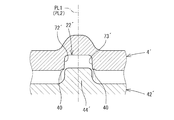
- the material of the end portion of the separator tube plastically flows in the circumferential direction and the axial direction, and an acute-angled ridge along the circumferential direction is formed at the groove angle of the seal ring groove.
- the gap (clearance) between the cylinder and the separator tube is close to zero, the sharp bulge is not a problem.
- the seal ring repeats a minute protrusion and return from the seal ring groove. Accordingly, when the backup ring is not used, the minute protrusion of the seal ring repeatedly passes through the sharp ridge, and as a result, the seal ring may be damaged.
- the present invention has been made in view of the above circumstances, and in a tube in which a seal ring groove is formed by sequential rotation processing and a shock absorber including the tube, the durability of the seal ring mounted in the seal ring groove is improved. It was made as an issue.
- the tube of the present invention is a tube having a seal ring groove on the inner periphery on the end side, and the seal ring groove is a pair of side surfaces facing each other across the bottom surface and the seal ring. And at least one of the side surfaces has an inclination angle of 5 ° or more with respect to a plane perpendicular to the axis of the tube.
- a shock absorber is a shock absorber attached between two members that are relatively movable, a cylinder in which a working fluid is sealed, a piston that is inserted into the cylinder, A piston rod connected to the piston and extending to the outside of the cylinder, an outer tube provided on the outer periphery of the cylinder, and a cylinder provided on the outer periphery of the cylinder and forming an annular passage communicating with the inside of the cylinder
- a separator tube having a cylindrical side wall, a reservoir formed outside the separator tube between the cylinder and the outer tube and enclosing a working fluid and a gas, and a damping force disposed outside the outer tube
- a seal ring groove extending in the circumferential direction is formed on the inner periphery of the separator tube on the end side.
- an inclination angle of a side surface located on the opening end side of the separator tube among a pair of side surfaces opposed to each other with the seal ring interposed therebetween is positioned on the opposite side with respect to a plane perpendicular to the axis of the separator tube. It is characterized by being larger than the inclination angle of the side surface.
- the durability of the seal ring mounted in the seal ring groove can be improved in the tube in which the seal ring groove is formed by rotational sequential processing and the shock absorber provided with the tube.
- the shock absorber 1 (hereinafter referred to as the shock absorber 1) of this embodiment will be described.
- the vertical direction in FIG. 1 is defined as the vertical direction of the shock absorber 1.
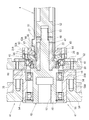
- the shock absorber 1 has a double cylinder structure including an outer tube 2 and a cylinder 3, and a separator tube 4 (tube) is provided on the outer periphery of the cylinder 3.
- a reservoir 5 that is an annular space is formed in a portion outside the separator tube 4 between the outer tube 2 and the cylinder 3.
- a piston 6 is slidably inserted.
- the piston 6 is fixed to one end of the piston rod 8 by a nut 7 and divides the inside of the cylinder 3 into a first chamber 3A and a second chamber 3B.
- the piston rod 8 extends to the outside of the cylinder 3 through the rod guide 9 and the oil seal 10 attached to the outer tube 2 and the upper end portion of the cylinder 3.
- the piston 6 has oil passages 11 and 12 that communicate between the first chamber 3A and the second chamber 3B.
- a check valve 13 On the surface of the piston 6 on the first chamber 3A side, a check valve 13 that allows only the flow of the oil liquid from the second chamber 3B side to the first chamber 3A side in the oil passage 11 is provided.
- the surface of the piston 6 on the second chamber 3B side is opened when the pressure of the oil liquid on the first chamber 3A side reaches a certain pressure, and the oil liquid on the first chamber 3A side passes through the oil passage 12.
- a disk valve 14 is provided for relief toward the second chamber 3B.
- the shock absorber 1 includes a base valve 15 that is provided at the lower end of the cylinder 3 and separates the second chamber 3B and the reservoir 5.
- the base valve 15 has oil passages 16 and 17 that connect the second chamber 3 ⁇ / b> B and the reservoir 5.
- the base valve 15 includes a check valve 18 that allows only the fluid to flow from the reservoir 5 side through the oil passage 16 to the second chamber 3B side.
- the base valve 15 opens when the pressure of the oil liquid on the second chamber 3B side reaches a constant pressure, and the base valve 15 relieves the oil liquid on the second chamber 3B side to the reservoir 5 side through the oil passage 17. 19
- An oil liquid is sealed as a working fluid inside the cylinder 3, and an oil liquid and a gas are sealed inside the reservoir 5.
- the separator tube 4 has seal ring grooves 22 and 22 (housing) in which O-rings 23 and 23 (seal rings) are attached by extending the inner circumferences 21 and 21 of both ends 20 and 20 in the circumferential direction.
- An annular oil passage 24 is formed between the cylinder 3 and the separator tube 4 by bringing the O-rings 23 and 23 of the both end portions 20 and 20 of the separator tube 4 into close contact with the outer periphery of the cylinder 3. 24 is communicated with the first chamber 3 ⁇ / b> A by an oil passage 25 provided at the upper end of the cylinder 3.
- a small-diameter opening 26 is provided at the lower end of the separator tube 4.
- the outer tube 2 is provided with a large-diameter opening 27 disposed corresponding to the opening 26, and a damping force generating mechanism 28 is attached to the opening 27 of the outer tube 2.
- the damping force generation mechanism 28 has a cylindrical case 29 attached to the opening 27.
- a solenoid valve 31 is fixed to the case 29 by a nut 32.
- the solenoid valve 31 mainly includes a pilot type (back pressure type) main damping valve 30 and a pressure control valve that controls the valve opening pressure of the main damping valve 30 by a solenoid.
- the solenoid valve 31 is connected to the opening 26 and controls the flow of oil from the opening 26 to the reservoir 5 to generate a damping force.
- the main damping valve 30 has a disc valve 33 and a back pressure chamber 34 formed on the back side of the disc valve 33.
- the disc valve 33 opens by receiving and bending the pressure of the oil liquid on the opening 26 side, thereby functioning as a main valve that distributes the oil liquid on the opening 26 side to the reservoir 5 side.
- the back pressure chamber 34 applies the internal pressure on the back side of the disc valve 33 in the valve closing direction of the disc valve 33.
- a sub passage 36 is connected to the opening 26 via a fixed orifice 35.
- the auxiliary passage 36 communicates with the back pressure chamber 34 through the passage 36A.
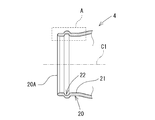
- FIG. 2 is a cross-sectional view of the separator tube 4 taken along an axial plane (a plane including the central axis C1), and particularly shows a cross section of one end 20 of the separator tube 4.
- one end 20 and the other end 20 of the separator tube 4 are vertically symmetrical in FIG.
- the separator tube 4 that is vertically symmetric with respect to one end 20 and the other end 20 will be described.
- only the other end 20 may be provided with a backup seal before and after the seal ring groove. .
- the other end 20 may have a seal ring groove shape different from the one end.
- the end portion 20 of the separator tube 4 is formed with a seal ring groove 22 on the inner circumference 21 by beading (sequential rotation processing), but is previously reduced in diameter by swaging.
- the seal ring groove 22 is formed in a substantially quadrangular cross section having a bottom surface 71 and a pair of side surfaces 72 and 73 facing each other with the O-ring 23 (see FIG. 1) interposed therebetween. .
- the side surface 72 located on the opening end 20A side (left side in FIGS. 2 and 3) of the end portion 20 of the separator tube 4 is open to the opening end 20A side.
- the inclination angle ⁇ 1 is set to 5 ° or more as will be described later, and in particular, is set to 20 ° in the present embodiment.
- the inclination angle ⁇ 2 (not shown) of the side surface 73 on the side opposite to the side surface 72 (the right side in FIGS. 2 and 3) with respect to the axis perpendicular to the axis PL1 is 0 ° to 5 based on the housing shape defined in JISB2401. Set to °. That is, the inclination angle ⁇ 1 with respect to the axis perpendicular plane PL1 of the side surface 72 located on the opening end 20A side is larger than the inclination angle ⁇ 2 with respect to the axis perpendicular plane PL1 of the side surface 73 located on the opposite side ( ⁇ 1> ⁇ 2).
- the side surface 72 and the side surface 73 are asymmetric with respect to the axis perpendicular to the axis PL1, and the seal ring groove 22 is asymmetric with respect to the axis perpendicular to the axis PL1.
- the seal ring groove 22 has a roundness at a groove angle, that is, a connecting portion between the opening end of the seal ring groove 22 and the inner periphery 21.
- the roundness of the groove angle on the side surface 72 side is defined as the roundness R of the groove angle.
- the roundness R of the groove angle of the seal ring groove 22 and the roundness of the groove angle on the side surface 73 side conform to the roundness of the groove angle of the housing specified in JISB2401.
- the seal ring groove 22 has a rounded groove bottom of the housing defined in JISB2401.
- a gap (clearance for ensuring assemblability) defined in JISB2401 is provided between the cylinder 2 (see FIG. 1) and the inner periphery 20 of the separator tube 4.
- a beading device 41 for beading (rotating sequentially) the seal ring groove 22 on the inner periphery 21 of the end 20 of the separator tube 4 will be described.
- the both ends 20 and 20 of the separator tube 4 are processed simultaneously by a pair of beading processing apparatus 41, here, only one beading processing apparatus 41 corresponding to one end 20 of the separator tube 4 is used. Is illustrated.
- the vertical direction and the horizontal direction in FIG. 4 are defined as the vertical direction and the horizontal direction of the beading processing device 41.
- the both ends 20 and 20 of the separator tube 4 may not be simultaneously processed by the pair of beading processing devices 41 but may be processed alternately by using one beading processing device.
- the beading processing device 41 includes a hollow shaft-shaped roller die 42 inserted on the inner periphery 21 side of the end portion 20 of the separator tube 4 and an outer mold 43 attached to the outer periphery of the end portion 20 of the separator tube 4.
- the roller die 42 has an annular convex portion 44 that extends in the circumferential direction on the outer periphery of the roller die 42.
- the convex portion 44 is provided at an intermediate position of the roller die 42, that is, at an intermediate position in the direction of the central axis C2 of the roller die 42 (the left-right direction in FIG. 5). Is done.
- the side surface 75 of the convex portion 44 corresponding to the side surface 72 located on the opening end 20A side of the separator tube 4, that is, the side on which the side surface 72 is molded.
- the side surface 75 corresponds to the inclination angle ⁇ 1 of the side surface 72 of the seal ring groove 22 and lies on the side surface 76 located on the opposite side, and includes a plane perpendicular to the axis of the roller die 42 (including a straight line orthogonal to the central axis C2). It is inclined at an inclination angle ⁇ 1 with respect to the plane PL2).
- the roller die 42 has a flange portion 45 provided at a distance from the side surface 75 of the convex portion 44 in the direction of the central axis C2 (left direction in FIG. 5).
- the beading machine 41 has a rotation drive mechanism 47 that drives the roller die 42 to rotate about the central axis C2 (see FIG. 5).
- the rotation drive mechanism 47 includes a die support portion 48 that supports the roller die 42 and a servo motor (not shown) as a drive source.
- the die support portion 48 includes a base portion 50 formed in a substantially cylindrical shape, a first shaft portion 51 in which the inner periphery of the roller die 42 is fitted to the outer periphery, and a second shaft portion 53 connected to the restriction member 52.
- Have The die support portion 48 is supported by a pair of bearings 54 that are arranged with an outer periphery of the base portion 50 spaced apart in the central axis direction (left-right direction in FIG.
- the pair of bearings 54 are accommodated in a substantially cylindrical bearing case 55, and the flange 55 ⁇ / b> A of the bearing case 55 is bolted to the boss 56 ⁇ / b> A of the motor base 56.
- the die support portion 48 has a hole 57 that is opened on the left end surface of the base portion 50, and is connected to a rotor shaft (not shown) of a servo motor inserted into the hole 57 so that power can be transmitted.
- the die support portion 48 has a flange portion 58 formed at the right end portion of the base portion 50, and the right bearing 54 abuts on the left end surface of the flange portion 58. Further, the flange portion 45 of the roller die 42 is brought into contact with the inner peripheral side of the right end surface of the flange portion 58, whereby the leftward movement of the roller die 42 with respect to the die support portion 48 is restricted. Then, the roller die 42 is restricted from moving in the right direction with respect to the die support portion 48 by the restriction member 52 in contact with the right end surface, and is thereby positioned in the axial direction with respect to the outer die 43.
- the left end of the roller die 42 is fitted into an annular recess 59 formed on the right end surface of the base 50. Further, the die support portion 48 is fitted into a hole 60 formed at the end surface of the restricting member 52 at the tip end portion of the first shaft portion 51.
- the outer die 43 is formed in a ring shape, and a roller die 42 is inserted on the inner peripheral side.
- the outer mold 43 is attached to the outer mold support plate 62 via a bearing 61. Accordingly, the outer mold 43 can rotate around the central axis of the outer mold 43. Further, the outer mold 43 has a concave portion 63 corresponding to the convex portion 44 of the roller die 42.
- An escape portion 65 for avoiding interference with the taper portion 64 of the separator tube 4 is formed inside the outer mold 43 and on the right side of the recess 63. Further, an abutting portion 66 having an inner diameter smaller than the inner diameter of the reference inner circumferential surface 43A of the outer mold 43 is formed inside the outer mold 43 and on the left side of the recess 63. The opening end 20 ⁇ / b> A of the end portion 20 of the separator tube 4 is abutted against the right end surface of the abutting portion 66. Thereby, as for the separator tube 4, the flow of the material at the time of beading processing is controlled.
- the outer die 43 is divided into two parts in the central axis direction (left and right direction in FIG. 4) and two parts in the radial direction (up and down direction in FIG. 4), for a total of four parts. By doing so, the separator tube 4 can be removed.
- symbol 68 shown by FIG. 4 is a bearing retainer fixed to the outer mold
- Reference numeral 69 denotes a bearing retainer that is fixed to the outer mold support plate 62 with bolts, and is for fixing the outer ring of the bearing 61 to the outer mold support plate 62.
- reference numeral 70 denotes a base plate to which the outer mold support plate 62 is attached via a pair of linear guides.
- the internal pressure of the first chamber 3A of the cylinder 3 fluctuates as the piston 6 slides, so that the O-ring 23 protrudes from the seal ring groove 22 ′. Repeat and return.
- the minute protrusion of the O-ring 23 repeatedly passes through the acute ridges 40 and 40, and as a result, the O-ring 23 may be damaged.
- the acute-angled ridges 40, 40 are more likely to occur as the groove width of the seal ring groove 22 'is smaller.
- the seal ring groove 22 of the separator tube 4 is formed asymmetrically with respect to the axis perpendicular to the axis PL1. Specifically, as shown in FIGS. 2 and 3, of the pair of side surfaces 72 and 73 of the seal ring groove 22, the side surface 72 positioned on the opening end 20 ⁇ / b> A side of the separator tube 4 is attached to the separator tube 4. It was inclined at an inclination angle ⁇ 1 of 5 ° or more with respect to the axis perpendicular to the axis PL1.
- the material of the separator tube 4 around the convex portion 44 of the roller die 42 can be more smoothly plastically flowed at the time of the rotation sequential processing, and among the side surface 72 and the side surface 73 of the seal ring groove 22, At least, it is possible to suppress the formation of the acute ridge 40 (see FIG. 6) at the groove angle on the side surface 72 side.
- FIG. 7 shows the test results obtained by the finite element method.
- the inclination angle ⁇ 1 (hereinafter referred to as the inclination) of the side surface 72 of the seal ring groove 22 with respect to the axis perpendicular to the axis PL1.
- 6 is a chart showing a relationship between an angle ⁇ 1) and a maximum tensile stress (MPa) acting on an O-ring 23 (material: NBR-90) mounted in the seal ring groove 22.
- MPa maximum tensile stress
- FIG. 8 is a chart showing the relationship between the inclination angle ⁇ 1 and the deformation (mm) of the end of the O-ring 23.
- the maximum tensile stress acting on the O-ring 23 tends to increase as the angle R of the seal ring groove 22 decreases with the inclination angle ⁇ 1 between 0 ° and 20 °.
- the inclination angle ⁇ 1 is 20 ° or less, the smaller the groove angle roundness R, the more concentrated the stress is on the portion (concave portion) that deforms along the groove angle roundness R of the O-ring 23. Presumed to be.
- FIG. 7 it is understood that the maximum tensile stress acting on the O-ring 23 is less affected by the roundness R of the groove angle when the inclination angle ⁇ 1 is equal to or greater than a certain value, and is stable in a state where the stress is small. it can.
- FIG. 8 shows that when the inclination angle ⁇ 1 exceeds 30 °, the deformation amount decreases once, and as the inclination angle ⁇ 1 increases, the deformation amount increases.
- the entry tip position of the O-ring 23 entering the gap between the cylinder 3 and the separator tube 4 is substantially the same.
- the approaching tip position of the O-ring 23 When it exceeds 40 °, the approaching tip position of the O-ring 23 is retracted, and at 60 °, the approaching tip position of the O-ring 23 is further retracted. That is, it can be said that the deformation mode has changed since the inclination angle ⁇ 1 exceeds 30 °.
- the deformation mode When the deformation mode is changed, the position of the leading end of the entry into the gap between the cylinder 3 and the separator tube 4 is retracted, resulting in a useless space and an increase in the axial length.
- the seal ring groove 22 has a groove angle, that is, a roundness R of a connecting portion between the opening end of the seal ring groove 22 and the inner periphery 21 is 0.2 mm or more and 1.0 mm or less. This is because, as shown in the results of FIG. 7, when R is 0.05 mm, the maximum tensile stress increases until the inclination angle ⁇ 1 reaches 20 °. When R is 0.05 mm or less, since the degree of sandwiching the O-ring 23 between the cylinder 3 and the separator tube 4 is large, the influence on the O-ring 23 entering the narrow gap between the cylinder 3 and the separator tube 4 is large. Conceivable. Further, as R is increased, the influence of the maximum tensile stress does not change, but the deformation mode changes. Therefore, for the reasons described above, R is preferably 1.0 mm or less.
- the maximum tensile stress acting on the O-ring 23 is approximately between the groove angle roundness R of 0.05 to 1.0 mm. It can be understood that they are the same and are not affected by the roundness R of the groove angle. However, if the inclination angle ⁇ 1 is set large, the maximum tensile stress acting on the O-ring 23 can be reduced. However, as can be seen from FIG. 9, the seal ring becomes larger as the inclination angle ⁇ 1 is set larger. The groove width of the groove 22 is increased, which causes structural design problems such as the necessity of extending the end 20 of the separator tube 4 in the central axis direction.
- the volume of the separator tube 4 cannot be secured sufficiently. Therefore, if the axial length of the separator tube 4 and the cylinder 3 are extended, the axial length of the shock absorber 1 as a whole becomes longer, resulting in a problem of an increase in size. Furthermore, the amount of deformation at the end of the O-ring 23 increases as the tilt angle ⁇ 1 increases. As a result, the degree of distortion of the O-ring 23 increases and the durability of the O-ring 23 decreases. In other words, the groove width of the seal ring groove 22 is increased, and further, the clearance between the cylinder 3 and the separator tube 4 is retreated, so that an axial gap is generated, so that the inclination angle ⁇ 1 increases. Therefore, it is desirable that the maximum value of the inclination angle ⁇ 1 at which the deformation mode does not change is 30 ° or less because the cylinder device is enlarged in the axial direction.
- the inclination angle ⁇ 1 of the seal ring groove 22 that can ensure the high durability of the O-ring 23 without causing a structural design problem and the inclination angle ⁇ 1 of 5 ° or more.
- FIG. 10 shows the test results when the inclination angle ⁇ 1 is changed from 2 ° to 10 ° in order to confirm whether or not the acute ridge 40 is generated at the groove angle of the seal ring groove 22 during the rotational sequential processing. Show. Since the acute ridge 40 was generated up to an inclination angle ⁇ 1 of 3 °, it was evaluated as x. When the inclination angle ⁇ 1 was 4 °, almost no acute ridge 40 was generated, but there was a slight bulge when touched with a hand. Therefore, it evaluated as (triangle
- the seal ring groove 22 is formed asymmetrically with respect to the plane perpendicular to the axis PL1 of the separator tube 4, and the separator of the pair of side surfaces 72 and 73 facing the O ring 23 (seal ring) of the seal ring groove 22 is sandwiched.
- the inclination angle ⁇ 1 of the side surface 72 located on the opening end 20A side of the tube 4 with respect to the axis perpendicular to the axis PL1 is set to 8 ° or more, and in particular, the inclination angle ⁇ 1 is set to 20 °.
- the maximum tensile stress acting on the O-ring 23 can be significantly reduced compared to the maximum tensile stress when the backup ring is used, and the durability of the O-ring 23 is increased by using the backup ring. It can be improved to the same or better time.
- the backup ring can be eliminated, the manufacturing cost of the shock absorber 1 can be greatly reduced, and the productivity can be improved because the assemblability is improved.
- an example of an O-ring is shown as the seal ring.
- the present invention is not limited to this, and the present invention is applicable to any seal ring such as a square ring having a rectangular cross section or a lip ring having a V-shaped cross section. Is also applicable.
Landscapes
- Engineering & Computer Science (AREA)
- General Engineering & Computer Science (AREA)
- Mechanical Engineering (AREA)
- Physics & Mathematics (AREA)
- Geometry (AREA)
- Life Sciences & Earth Sciences (AREA)
- Agronomy & Crop Science (AREA)
- Fluid-Damping Devices (AREA)
- Sealing Devices (AREA)
Abstract
Description
Claims (10)
- 端部側の内周にシールリング溝を有するチューブであって、前記シールリング溝は、底面とシールリングを挟んで相対する1対の側面とを有する断面略四角形状に形成され、少なくとも一方の前記側面は、前記チューブの軸直角平面に対する傾斜角度が5°以上であることを特徴とするチューブ。
- 前記傾斜角度を8°以上としたことを特徴とする請求項1に記載のチューブ。
- 前記傾斜角度を30°以下としたことを特徴とする請求項1に記載のチューブ。
- 前記傾斜角度を30°以下としたことを特徴とする請求項2に記載のチューブ。
- 前記少なくとも一方の前記側面と前記チューブの内面との繋がり部は、0.2mm以上のR面で接続されていることを特徴とする請求項1に記載のチューブ。
- 前記少なくとも一方の前記側面と前記チューブの内面との繋がり部は、0.2mm以上のR面で接続されていることを特徴とする請求項2に記載のチューブ。
- 前記少なくとも一方の前記側面と前記チューブの内面との繋がり部は、0.2mm以上のR面で接続されていることを特徴とする請求項3に記載のチューブ。
- 前記シールリング溝は、回転逐次加工により成形されることを特徴とする請求項1に記載のチューブ。
- 前記シールリング溝は、回転逐次加工により成形されることを特徴とする請求項2に記載のチューブ。
- 相対移動可能な2部材間に取り付けられる緩衝器であって、作動流体が封入されるシリンダと、前記シリンダ内に挿入されるピストンと、前記ピストンに連結されて前記シリンダの外部に延出するピストンロッドと、前記シリンダの外周に設けられるアウタチューブと、前記シリンダの外周囲に設けられ、前記シリンダ内と連通する環状通路を形成する円筒状の側壁を有するセパレータチューブと、前記シリンダと前記アウタチューブとの間の前記セパレータチューブの外側に形成されて作動流体およびガスが封入されるリザーバと、前記アウタチューブの外部に配置される減衰力発生機構と、を備え、前記セパレータチューブの端部側の内周には周方向へ延びるシールリング溝が形成され、前記シールリング溝は、シールリングを挟んで相対する1対の側面のうち、前記セパレータチューブの開口端側に位置する側面の、前記セパレータチューブの軸直角平面に対する傾斜角度が、反対側に位置する側面の前記傾斜角度よりも大きいことを特徴とする緩衝器。
Priority Applications (5)
| Application Number | Priority Date | Filing Date | Title |
|---|---|---|---|
| US14/779,645 US9707820B2 (en) | 2013-04-26 | 2014-03-25 | Tube and shock absorber |
| CN201480019287.0A CN105074264B (zh) | 2013-04-26 | 2014-03-25 | 筒以及缓冲器 |
| DE112014002179.2T DE112014002179T5 (de) | 2013-04-26 | 2014-03-25 | Rohr und Stoßdämpfer |
| KR1020157026683A KR102139397B1 (ko) | 2013-04-26 | 2014-03-25 | 튜브 및 완충기 |
| JP2015513629A JP6017681B2 (ja) | 2013-04-26 | 2014-03-25 | 緩衝器 |
Applications Claiming Priority (2)
| Application Number | Priority Date | Filing Date | Title |
|---|---|---|---|
| JP2013-094047 | 2013-04-26 | ||
| JP2013094047 | 2013-04-26 |
Publications (1)
| Publication Number | Publication Date |
|---|---|
| WO2014174966A1 true WO2014174966A1 (ja) | 2014-10-30 |
Family
ID=51791549
Family Applications (1)
| Application Number | Title | Priority Date | Filing Date |
|---|---|---|---|
| PCT/JP2014/058304 Ceased WO2014174966A1 (ja) | 2013-04-26 | 2014-03-25 | チューブおよび緩衝器 |
Country Status (6)
| Country | Link |
|---|---|
| US (1) | US9707820B2 (ja) |
| JP (1) | JP6017681B2 (ja) |
| KR (1) | KR102139397B1 (ja) |
| CN (1) | CN105074264B (ja) |
| DE (1) | DE112014002179T5 (ja) |
| WO (1) | WO2014174966A1 (ja) |
Cited By (1)
| Publication number | Priority date | Publication date | Assignee | Title |
|---|---|---|---|---|
| TWI681142B (zh) * | 2015-10-27 | 2020-01-01 | 日商日鐵日新製鋼股份有限公司 | 管狀構造物及其製造方法 |
Families Citing this family (8)
| Publication number | Priority date | Publication date | Assignee | Title |
|---|---|---|---|---|
| USD811281S1 (en) * | 2015-12-21 | 2018-02-27 | Y.S.S. (Thailand) Co., Ltd. | Shock absorber |
| US9744888B1 (en) * | 2016-02-11 | 2017-08-29 | Ford Global Technologies, Llc | Integrated cooling system for an adjustable headrest assembly |
| IT201600120936A1 (it) * | 2016-11-29 | 2018-05-29 | Giacomini Spa | Giunzione per tubazioni metalliche |
| IT201700006900A1 (it) * | 2017-01-23 | 2018-07-23 | Sistemi Sospensioni Spa | Attuatore lineare idraulico con sistema di bloccaggio atto a bloccare il movimento di compressione dell'attuatore. |
| JP6771522B2 (ja) | 2018-10-09 | 2020-10-21 | Kyb株式会社 | 緩衝器 |
| CN112377553B (zh) * | 2020-02-25 | 2022-03-29 | 北京京西重工有限公司 | 阻尼器组件和用于其的壳体 |
| DE102020210538A1 (de) * | 2020-08-19 | 2022-02-24 | Thyssenkrupp Ag | Schwingungsdämpfer und ein Dämpferrohr für einen Schwingungsdämpfer |
| CN113252342A (zh) * | 2021-04-02 | 2021-08-13 | 南京航空航天大学 | 一种可调整密封圈沟槽宽度的密封圈性能试验装置 |
Citations (4)
| Publication number | Priority date | Publication date | Assignee | Title |
|---|---|---|---|---|
| JPS61139328U (ja) * | 1985-02-19 | 1986-08-29 | ||
| US20030155198A1 (en) * | 2002-02-20 | 2003-08-21 | Mannesmann Sachs Ag | Shock absorber |
| JP2010053990A (ja) * | 2008-08-29 | 2010-03-11 | Toyota Motor Corp | シール構造 |
| JP2013015163A (ja) * | 2011-06-30 | 2013-01-24 | Hitachi Automotive Systems Ltd | 緩衝器 |
Family Cites Families (8)
| Publication number | Priority date | Publication date | Assignee | Title |
|---|---|---|---|---|
| JPS61139328A (ja) | 1984-12-10 | 1986-06-26 | 田幡 久雄 | まきえを付けやすく、落下しにくくした浮きづり仕掛け |
| JPH0544550Y2 (ja) * | 1985-02-20 | 1993-11-11 | ||
| CN86204629U (zh) * | 1986-07-05 | 1987-06-17 | 国家地震局工程力学研究所 | 梯形沟槽o环超高压密封结构 |
| CN2396240Y (zh) * | 1999-09-29 | 2000-09-13 | 韩育智 | 一种液压减震器密封装置 |
| DE10033348A1 (de) * | 2000-07-08 | 2002-01-17 | Bosch Gmbh Robert | Dichtungsanordnung an einem Aggregat |
| JP4911275B2 (ja) * | 2005-06-24 | 2012-04-04 | Nok株式会社 | 密封構造 |
| JP4962687B2 (ja) * | 2005-08-30 | 2012-06-27 | Nok株式会社 | 密封構造 |
| JP2014069210A (ja) * | 2012-09-28 | 2014-04-21 | Hitachi Automotive Systems Ltd | チューブの加工方法及び緩衝器 |
-
2014
- 2014-03-25 US US14/779,645 patent/US9707820B2/en active Active
- 2014-03-25 JP JP2015513629A patent/JP6017681B2/ja active Active
- 2014-03-25 KR KR1020157026683A patent/KR102139397B1/ko active Active
- 2014-03-25 WO PCT/JP2014/058304 patent/WO2014174966A1/ja not_active Ceased
- 2014-03-25 DE DE112014002179.2T patent/DE112014002179T5/de active Granted
- 2014-03-25 CN CN201480019287.0A patent/CN105074264B/zh active Active
Patent Citations (4)
| Publication number | Priority date | Publication date | Assignee | Title |
|---|---|---|---|---|
| JPS61139328U (ja) * | 1985-02-19 | 1986-08-29 | ||
| US20030155198A1 (en) * | 2002-02-20 | 2003-08-21 | Mannesmann Sachs Ag | Shock absorber |
| JP2010053990A (ja) * | 2008-08-29 | 2010-03-11 | Toyota Motor Corp | シール構造 |
| JP2013015163A (ja) * | 2011-06-30 | 2013-01-24 | Hitachi Automotive Systems Ltd | 緩衝器 |
Cited By (1)
| Publication number | Priority date | Publication date | Assignee | Title |
|---|---|---|---|---|
| TWI681142B (zh) * | 2015-10-27 | 2020-01-01 | 日商日鐵日新製鋼股份有限公司 | 管狀構造物及其製造方法 |
Also Published As
| Publication number | Publication date |
|---|---|
| US9707820B2 (en) | 2017-07-18 |
| JP6017681B2 (ja) | 2016-11-02 |
| DE112014002179T5 (de) | 2015-12-31 |
| CN105074264B (zh) | 2018-08-17 |
| KR102139397B1 (ko) | 2020-07-29 |
| US20160052361A1 (en) | 2016-02-25 |
| KR20160003640A (ko) | 2016-01-11 |
| JPWO2014174966A1 (ja) | 2017-02-23 |
| CN105074264A (zh) | 2015-11-18 |
Similar Documents
| Publication | Publication Date | Title |
|---|---|---|
| JP6017681B2 (ja) | 緩衝器 | |
| JP2014069210A5 (ja) | ||
| JP2014069210A (ja) | チューブの加工方法及び緩衝器 | |
| KR101366140B1 (ko) | 예압조정을 위한 스트로크의 극간 및 실링재의 탄성변형을 이용한 베어링의 가변 예압 시스템 | |
| EP2282091A1 (en) | Proportional electromagnetic flow control valve | |
| WO2018030195A1 (ja) | シリンダ装置、及びシリンダ装置の製造方法 | |
| KR102589604B1 (ko) | 완충기 및 완충기의 조립 방법 | |
| JP6611544B2 (ja) | 接合体、流体圧シリンダ、及び接合体の製造方法 | |
| JP2016524110A (ja) | 予圧の調整のためのストロークの隙間及びシーリング材の弾性変形を用いた軸受の可変予圧システム | |
| JP6516916B2 (ja) | 減衰力調整式緩衝器 | |
| WO2013129589A1 (ja) | シリンダ装置の製造方法 | |
| JP5113499B2 (ja) | クランプスリーブおよび割出装置のクランプ装置 | |
| CN104685224A (zh) | 流体压缸 | |
| CN103518069B (zh) | 流体压力缸的缓冲机构 | |
| JP7104824B2 (ja) | シリンダ装置、及びシリンダ装置の製造方法 | |
| KR20150103334A (ko) | 유체압 실린더 및 그 제조 방법 | |
| US20190226548A1 (en) | Shock absorber | |
| JP2015197126A (ja) | 緩衝器 | |
| JP5563506B2 (ja) | 流体圧シリンダのクッション機構 | |
| JP5583623B2 (ja) | 流体圧シリンダのクッション機構 | |
| JP2023120536A (ja) | シリンダ装置 | |
| CN117090890A (zh) | 用于调整阻尼阀装置的方法 | |
| JP2010281374A (ja) | バルブ装置 | |
| CN121251726A (zh) | 一种自调阻尼减震器 | |
| WO2019106918A1 (ja) | シリンダ装置およびその製造方法 |
Legal Events
| Date | Code | Title | Description |
|---|---|---|---|
| WWE | Wipo information: entry into national phase |
Ref document number: 201480019287.0 Country of ref document: CN |
|
| 121 | Ep: the epo has been informed by wipo that ep was designated in this application |
Ref document number: 14789071 Country of ref document: EP Kind code of ref document: A1 |
|
| ENP | Entry into the national phase |
Ref document number: 2015513629 Country of ref document: JP Kind code of ref document: A |
|
| WWE | Wipo information: entry into national phase |
Ref document number: 14779645 Country of ref document: US |
|
| ENP | Entry into the national phase |
Ref document number: 20157026683 Country of ref document: KR Kind code of ref document: A |
|
| WWE | Wipo information: entry into national phase |
Ref document number: 1120140021792 Country of ref document: DE Ref document number: 112014002179 Country of ref document: DE |
|
| 122 | Ep: pct application non-entry in european phase |
Ref document number: 14789071 Country of ref document: EP Kind code of ref document: A1 |