WO2014170948A1 - ハイブリッド車両の制御装置 - Google Patents
ハイブリッド車両の制御装置 Download PDFInfo
- Publication number
- WO2014170948A1 WO2014170948A1 PCT/JP2013/061232 JP2013061232W WO2014170948A1 WO 2014170948 A1 WO2014170948 A1 WO 2014170948A1 JP 2013061232 W JP2013061232 W JP 2013061232W WO 2014170948 A1 WO2014170948 A1 WO 2014170948A1
- Authority
- WO
- WIPO (PCT)
- Prior art keywords
- engine
- clutch
- vibration
- driving force
- vehicle
- Prior art date
- Legal status (The legal status is an assumption and is not a legal conclusion. Google has not performed a legal analysis and makes no representation as to the accuracy of the status listed.)
- Ceased
Links
Images


Classifications
-
- B—PERFORMING OPERATIONS; TRANSPORTING
- B60—VEHICLES IN GENERAL
- B60K—ARRANGEMENT OR MOUNTING OF PROPULSION UNITS OR OF TRANSMISSIONS IN VEHICLES; ARRANGEMENT OR MOUNTING OF PLURAL DIVERSE PRIME-MOVERS IN VEHICLES; AUXILIARY DRIVES FOR VEHICLES; INSTRUMENTATION OR DASHBOARDS FOR VEHICLES; ARRANGEMENTS IN CONNECTION WITH COOLING, AIR INTAKE, GAS EXHAUST OR FUEL SUPPLY OF PROPULSION UNITS IN VEHICLES
- B60K6/00—Arrangement or mounting of plural diverse prime-movers for mutual or common propulsion, e.g. hybrid propulsion systems comprising electric motors and internal combustion engines
- B60K6/20—Arrangement or mounting of plural diverse prime-movers for mutual or common propulsion, e.g. hybrid propulsion systems comprising electric motors and internal combustion engines the prime-movers consisting of electric motors and internal combustion engines, e.g. HEVs
- B60K6/22—Arrangement or mounting of plural diverse prime-movers for mutual or common propulsion, e.g. hybrid propulsion systems comprising electric motors and internal combustion engines the prime-movers consisting of electric motors and internal combustion engines, e.g. HEVs characterised by apparatus, components or means specially adapted for HEVs
- B60K6/38—Arrangement or mounting of plural diverse prime-movers for mutual or common propulsion, e.g. hybrid propulsion systems comprising electric motors and internal combustion engines the prime-movers consisting of electric motors and internal combustion engines, e.g. HEVs characterised by apparatus, components or means specially adapted for HEVs characterised by the driveline clutches
-
- B—PERFORMING OPERATIONS; TRANSPORTING
- B60—VEHICLES IN GENERAL
- B60K—ARRANGEMENT OR MOUNTING OF PROPULSION UNITS OR OF TRANSMISSIONS IN VEHICLES; ARRANGEMENT OR MOUNTING OF PLURAL DIVERSE PRIME-MOVERS IN VEHICLES; AUXILIARY DRIVES FOR VEHICLES; INSTRUMENTATION OR DASHBOARDS FOR VEHICLES; ARRANGEMENTS IN CONNECTION WITH COOLING, AIR INTAKE, GAS EXHAUST OR FUEL SUPPLY OF PROPULSION UNITS IN VEHICLES
- B60K6/00—Arrangement or mounting of plural diverse prime-movers for mutual or common propulsion, e.g. hybrid propulsion systems comprising electric motors and internal combustion engines
- B60K6/20—Arrangement or mounting of plural diverse prime-movers for mutual or common propulsion, e.g. hybrid propulsion systems comprising electric motors and internal combustion engines the prime-movers consisting of electric motors and internal combustion engines, e.g. HEVs
- B60K6/42—Arrangement or mounting of plural diverse prime-movers for mutual or common propulsion, e.g. hybrid propulsion systems comprising electric motors and internal combustion engines the prime-movers consisting of electric motors and internal combustion engines, e.g. HEVs characterised by the architecture of the hybrid electric vehicle
- B60K6/48—Parallel type
-
- B—PERFORMING OPERATIONS; TRANSPORTING
- B60—VEHICLES IN GENERAL
- B60K—ARRANGEMENT OR MOUNTING OF PROPULSION UNITS OR OF TRANSMISSIONS IN VEHICLES; ARRANGEMENT OR MOUNTING OF PLURAL DIVERSE PRIME-MOVERS IN VEHICLES; AUXILIARY DRIVES FOR VEHICLES; INSTRUMENTATION OR DASHBOARDS FOR VEHICLES; ARRANGEMENTS IN CONNECTION WITH COOLING, AIR INTAKE, GAS EXHAUST OR FUEL SUPPLY OF PROPULSION UNITS IN VEHICLES
- B60K6/00—Arrangement or mounting of plural diverse prime-movers for mutual or common propulsion, e.g. hybrid propulsion systems comprising electric motors and internal combustion engines
- B60K6/20—Arrangement or mounting of plural diverse prime-movers for mutual or common propulsion, e.g. hybrid propulsion systems comprising electric motors and internal combustion engines the prime-movers consisting of electric motors and internal combustion engines, e.g. HEVs
- B60K6/22—Arrangement or mounting of plural diverse prime-movers for mutual or common propulsion, e.g. hybrid propulsion systems comprising electric motors and internal combustion engines the prime-movers consisting of electric motors and internal combustion engines, e.g. HEVs characterised by apparatus, components or means specially adapted for HEVs
- B60K6/38—Arrangement or mounting of plural diverse prime-movers for mutual or common propulsion, e.g. hybrid propulsion systems comprising electric motors and internal combustion engines the prime-movers consisting of electric motors and internal combustion engines, e.g. HEVs characterised by apparatus, components or means specially adapted for HEVs characterised by the driveline clutches
- B60K6/387—Actuated clutches, i.e. clutches engaged or disengaged by electric, hydraulic or mechanical actuating means
-
- B—PERFORMING OPERATIONS; TRANSPORTING
- B60—VEHICLES IN GENERAL
- B60W—CONJOINT CONTROL OF VEHICLE SUB-UNITS OF DIFFERENT TYPE OR DIFFERENT FUNCTION; CONTROL SYSTEMS SPECIALLY ADAPTED FOR HYBRID VEHICLES; ROAD VEHICLE DRIVE CONTROL SYSTEMS FOR PURPOSES NOT RELATED TO THE CONTROL OF A PARTICULAR SUB-UNIT
- B60W10/00—Conjoint control of vehicle sub-units of different type or different function
- B60W10/02—Conjoint control of vehicle sub-units of different type or different function including control of driveline clutches
-
- B—PERFORMING OPERATIONS; TRANSPORTING
- B60—VEHICLES IN GENERAL
- B60W—CONJOINT CONTROL OF VEHICLE SUB-UNITS OF DIFFERENT TYPE OR DIFFERENT FUNCTION; CONTROL SYSTEMS SPECIALLY ADAPTED FOR HYBRID VEHICLES; ROAD VEHICLE DRIVE CONTROL SYSTEMS FOR PURPOSES NOT RELATED TO THE CONTROL OF A PARTICULAR SUB-UNIT
- B60W10/00—Conjoint control of vehicle sub-units of different type or different function
- B60W10/04—Conjoint control of vehicle sub-units of different type or different function including control of propulsion units
- B60W10/06—Conjoint control of vehicle sub-units of different type or different function including control of propulsion units including control of combustion engines
-
- B—PERFORMING OPERATIONS; TRANSPORTING
- B60—VEHICLES IN GENERAL
- B60W—CONJOINT CONTROL OF VEHICLE SUB-UNITS OF DIFFERENT TYPE OR DIFFERENT FUNCTION; CONTROL SYSTEMS SPECIALLY ADAPTED FOR HYBRID VEHICLES; ROAD VEHICLE DRIVE CONTROL SYSTEMS FOR PURPOSES NOT RELATED TO THE CONTROL OF A PARTICULAR SUB-UNIT
- B60W10/00—Conjoint control of vehicle sub-units of different type or different function
- B60W10/04—Conjoint control of vehicle sub-units of different type or different function including control of propulsion units
- B60W10/08—Conjoint control of vehicle sub-units of different type or different function including control of propulsion units including control of electric propulsion units, e.g. motors or generators
-
- B—PERFORMING OPERATIONS; TRANSPORTING
- B60—VEHICLES IN GENERAL
- B60W—CONJOINT CONTROL OF VEHICLE SUB-UNITS OF DIFFERENT TYPE OR DIFFERENT FUNCTION; CONTROL SYSTEMS SPECIALLY ADAPTED FOR HYBRID VEHICLES; ROAD VEHICLE DRIVE CONTROL SYSTEMS FOR PURPOSES NOT RELATED TO THE CONTROL OF A PARTICULAR SUB-UNIT
- B60W20/00—Control systems specially adapted for hybrid vehicles
-
- B—PERFORMING OPERATIONS; TRANSPORTING
- B60—VEHICLES IN GENERAL
- B60W—CONJOINT CONTROL OF VEHICLE SUB-UNITS OF DIFFERENT TYPE OR DIFFERENT FUNCTION; CONTROL SYSTEMS SPECIALLY ADAPTED FOR HYBRID VEHICLES; ROAD VEHICLE DRIVE CONTROL SYSTEMS FOR PURPOSES NOT RELATED TO THE CONTROL OF A PARTICULAR SUB-UNIT
- B60W20/00—Control systems specially adapted for hybrid vehicles
- B60W20/10—Controlling the power contribution of each of the prime movers to meet required power demand
- B60W20/15—Control strategies specially adapted for achieving a particular effect
-
- B—PERFORMING OPERATIONS; TRANSPORTING
- B60—VEHICLES IN GENERAL
- B60W—CONJOINT CONTROL OF VEHICLE SUB-UNITS OF DIFFERENT TYPE OR DIFFERENT FUNCTION; CONTROL SYSTEMS SPECIALLY ADAPTED FOR HYBRID VEHICLES; ROAD VEHICLE DRIVE CONTROL SYSTEMS FOR PURPOSES NOT RELATED TO THE CONTROL OF A PARTICULAR SUB-UNIT
- B60W20/00—Control systems specially adapted for hybrid vehicles
- B60W20/50—Control strategies for responding to system failures, e.g. for fault diagnosis, failsafe operation or limp mode
-
- B—PERFORMING OPERATIONS; TRANSPORTING
- B60—VEHICLES IN GENERAL
- B60W—CONJOINT CONTROL OF VEHICLE SUB-UNITS OF DIFFERENT TYPE OR DIFFERENT FUNCTION; CONTROL SYSTEMS SPECIALLY ADAPTED FOR HYBRID VEHICLES; ROAD VEHICLE DRIVE CONTROL SYSTEMS FOR PURPOSES NOT RELATED TO THE CONTROL OF A PARTICULAR SUB-UNIT
- B60W30/00—Purposes of road vehicle drive control systems not related to the control of a particular sub-unit, e.g. of systems using conjoint control of vehicle sub-units
- B60W30/18—Propelling the vehicle
- B60W30/192—Mitigating problems related to power-up or power-down of the driveline, e.g. start-up of a cold engine
- B60W30/194—Mitigating problems related to power-up or power-down of the driveline, e.g. start-up of a cold engine related to low temperature conditions, e.g. high viscosity of hydraulic fluid
-
- B—PERFORMING OPERATIONS; TRANSPORTING
- B60—VEHICLES IN GENERAL
- B60W—CONJOINT CONTROL OF VEHICLE SUB-UNITS OF DIFFERENT TYPE OR DIFFERENT FUNCTION; CONTROL SYSTEMS SPECIALLY ADAPTED FOR HYBRID VEHICLES; ROAD VEHICLE DRIVE CONTROL SYSTEMS FOR PURPOSES NOT RELATED TO THE CONTROL OF A PARTICULAR SUB-UNIT
- B60W30/00—Purposes of road vehicle drive control systems not related to the control of a particular sub-unit, e.g. of systems using conjoint control of vehicle sub-units
- B60W30/18—Propelling the vehicle
- B60W30/20—Reducing vibrations in the driveline
- B60W2030/206—Reducing vibrations in the driveline related or induced by the engine
-
- B—PERFORMING OPERATIONS; TRANSPORTING
- B60—VEHICLES IN GENERAL
- B60W—CONJOINT CONTROL OF VEHICLE SUB-UNITS OF DIFFERENT TYPE OR DIFFERENT FUNCTION; CONTROL SYSTEMS SPECIALLY ADAPTED FOR HYBRID VEHICLES; ROAD VEHICLE DRIVE CONTROL SYSTEMS FOR PURPOSES NOT RELATED TO THE CONTROL OF A PARTICULAR SUB-UNIT
- B60W2510/00—Input parameters relating to a particular sub-units
- B60W2510/06—Combustion engines, Gas turbines
- B60W2510/0638—Engine speed
- B60W2510/0652—Speed change rate
-
- Y—GENERAL TAGGING OF NEW TECHNOLOGICAL DEVELOPMENTS; GENERAL TAGGING OF CROSS-SECTIONAL TECHNOLOGIES SPANNING OVER SEVERAL SECTIONS OF THE IPC; TECHNICAL SUBJECTS COVERED BY FORMER USPC CROSS-REFERENCE ART COLLECTIONS [XRACs] AND DIGESTS
- Y02—TECHNOLOGIES OR APPLICATIONS FOR MITIGATION OR ADAPTATION AGAINST CLIMATE CHANGE
- Y02T—CLIMATE CHANGE MITIGATION TECHNOLOGIES RELATED TO TRANSPORTATION
- Y02T10/00—Road transport of goods or passengers
- Y02T10/60—Other road transportation technologies with climate change mitigation effect
- Y02T10/62—Hybrid vehicles
-
- Y—GENERAL TAGGING OF NEW TECHNOLOGICAL DEVELOPMENTS; GENERAL TAGGING OF CROSS-SECTIONAL TECHNOLOGIES SPANNING OVER SEVERAL SECTIONS OF THE IPC; TECHNICAL SUBJECTS COVERED BY FORMER USPC CROSS-REFERENCE ART COLLECTIONS [XRACs] AND DIGESTS
- Y10—TECHNICAL SUBJECTS COVERED BY FORMER USPC
- Y10S—TECHNICAL SUBJECTS COVERED BY FORMER USPC CROSS-REFERENCE ART COLLECTIONS [XRACs] AND DIGESTS
- Y10S903/00—Hybrid electric vehicles, HEVS
- Y10S903/902—Prime movers comprising electrical and internal combustion motors
- Y10S903/903—Prime movers comprising electrical and internal combustion motors having energy storing means, e.g. battery, capacitor
- Y10S903/946—Characterized by control of driveline clutch
Definitions
- the present invention relates to a control device for a hybrid vehicle, and particularly relates to improvement of drivability.
- a technology has been proposed for defrosting the engine throttle valve when it occurs in a low temperature environment.
- a motor that controls the opening of the throttle valve via a gear mechanism is used, and the motor is rotated while the motor is rotated by the clearance of the gear of the gear mechanism. Accelerate.
- the throttle valve is allowed to escape from the icing state by increasing the driving force acting on the throttle valve from the motor via the gear mechanism.
- the engine may be stopped during traveling, and the frequency of operation of the engine is reduced. Accordingly, since there is a high possibility that icing will occur, a countermeasure for quickly icing this icing has been desired.
- the present invention has been made in the background of the above circumstances, and its purpose is to deteriorate the drivability when engine vibration is detected during engine operation or when occurrence of engine vibration is predicted.
- An object of the present invention is to provide a control device for a hybrid vehicle that can eliminate engine vibration without causing it to occur.
- the gist of the first invention includes (a) an engine, an electric motor connected to a power transmission path between the engine and driving wheels, the engine, the electric motor, and a drive.
- a hybrid vehicle having a clutch for connecting / disconnecting a power transmission path to / from the wheels, and detecting engine vibration occurring at a temperature equal to or lower than a predetermined low-temperature judgment value at which icing of the intake and exhaust valves of the engine is predicted to occur (B)
- the engagement state of the clutch is changed based on the required driving force of the vehicle.
- the slip amount of the clutch is reduced as the required driving force of the vehicle is increased as compared with a case where the required driving force is small.
- the required driving force is large, the vehicle is driven by the engine torque and the motor torque. Further, as the required driving force increases, the engine torque increases. However, when the engine torque increases, the combustion stabilizes and the engine vibration tends to decrease. Therefore, vibration transmitted to the drive wheels is suppressed even when the slip amount of the clutch decreases.
- the required driving force is small, for example, the driving force can be covered by the motor torque, so that the clutch can be released or the slip amount can be increased to suppress the transmission of engine vibration to the driving wheels.
- the clutch is opened. In this way, engine vibration is not transmitted to the drive wheels, and drivability can be further improved. Moreover, running performance is also ensured by running with an electric motor.
- the slip amount of the clutch is reduced as the engine torque increases.
- the clutch engagement state is changed based on the required driving force of the vehicle and the engine output is increased.
- the engine output is increased to promote the temperature rise of the intake / exhaust valve.
- the deicing of the intake / exhaust valve can be promoted. .
- the generation of the engine vibration is generation of vibration with an irregular explosion cycle of the engine.
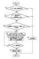
- FIG. 7 It is a figure explaining the schematic structure of the power transmission path from the engine which comprises the hybrid vehicle to which this invention is applied suitably, and an electric motor to a drive wheel. It is a functional block diagram explaining the principal part of the control function by the electronic controller of FIG. 7 is a flowchart for explaining a control operation of the electronic control device, that is, a control operation for eliminating engine vibration without deteriorating drivability when engine vibration resulting from icing of the intake and exhaust valves is detected during engine operation. .
- FIG. 1 is a diagram illustrating a schematic configuration of a power transmission path from an engine 14 and an electric motor MG to a drive wheel 34 constituting a hybrid vehicle 10 (hereinafter referred to as a vehicle 10) to which the present invention is preferably applied.
- FIG. 2 is a diagram illustrating a main part of a control system provided in a vehicle 10 for output control of an engine 14 that functions as a driving power source for traveling, shift control of an automatic transmission 18, drive control of an electric motor MG, and the like.
- a vehicle power transmission device 12 (hereinafter referred to as a power transmission device 12) is arranged on the engine 14 side in a transmission case 20 (hereinafter referred to as a case 20) as a non-rotating member attached to a vehicle body by bolting or the like.
- the engine connecting / disconnecting clutch K0, the electric motor MG, the torque converter 16, the oil pump 22, the automatic transmission 18 and the like are provided in order.
- the power transmission device 12 includes a propeller shaft 26 connected to an output shaft 24 that is an output rotating member of the automatic transmission 18, a differential gear device (differential gear) 28 connected to the propeller shaft 26, and a differential thereof.
- a pair of axles 30 and the like connected to the gear device 28 are provided.
- the power transmission device 12 configured in this manner is suitably used for, for example, an FR (front engine / rear drive) type vehicle 10.
- the power of the engine 14 is transmitted from the engine connecting shaft 32 that connects the engine 14 and the engine connecting / disconnecting clutch K0 to the engine connecting / disconnecting clutch.
- the power is transmitted to the pair of drive wheels 34 through the K0, the torque converter 16, the automatic transmission 18, the propeller shaft 26, the differential gear device 28, the pair of axles 30, and the like sequentially.
- the engine 14 is composed of, for example, a four-cylinder four-cycle gasoline engine, and is provided with two intake valves and two exhaust valves for each cylinder. In the present embodiment, these two intake valves and two exhaust valves provided for each cylinder are collectively referred to as an intake / exhaust valve 15.
- the torque converter 16 is a fluid transmission device that transmits the driving force input to the pump impeller 16a to the automatic transmission 18 side via a fluid.
- the pump impeller 16a is connected to the engine 14 through the engine connecting / disconnecting clutch K0 and the engine connecting shaft 32 in order, and the driving force from the engine 14 is input and the input side is rotatable about the axis. It is a rotating element.
- the turbine impeller 16b of the torque converter 16 is an output side rotating element of the torque converter 16, and is connected to a transmission input shaft 36, which is an input rotating member of the automatic transmission 18, so as not to be relatively rotatable by spline fitting or the like.
- the torque converter 16 includes a lockup clutch 38.
- the lock-up clutch 38 is a direct coupling clutch provided between the pump impeller 16a and the turbine impeller 16b, and is brought into an engaged state, a slip state, or a released state by hydraulic control or the like.
- the electric motor MG is connected to a power transmission path between the engine 14 and the drive wheels 34, functions as a motor that generates mechanical driving force from electric energy, and a generator that generates electric energy from mechanical energy.
- This is a so-called motor generator having a function as
- the electric motor MG can function as a driving power source for driving that generates driving power for driving together with the engine 14 as an alternative to the engine 14 that is a power source.
- electric energy is generated by regeneration from the driving force generated by the engine 14 or the driven force (mechanical energy) input from the driving wheel 34 side, and the electric energy is supplied to the inverter 40 or a boost converter (not shown).
- the battery 46 which is a power storage device.
- the electric motor MG is operatively connected to the pump impeller 16a, and power is transmitted between the electric motor MG and the pump impeller 16a. Therefore, similarly to the engine 14, the electric motor MG is connected to the transmission input shaft 36 so that power can be transmitted.
- the electric motor MG is connected to exchange power with the battery 46 via the inverter 40, a boost converter (not shown), and the like.
- the engine connecting / disconnecting clutch K0 is released, and the power of the electric motor MG is converted to the torque converter 16, the automatic transmission 18, the propeller shaft 26, and the differential gear device. 28 and a pair of axles 30 and the like are sequentially transmitted to a pair of drive wheels 34.
- the oil pump 22 is connected to the pump impeller 16a and controls the shift of the automatic transmission 18, controls the torque capacity of the lockup clutch 38, and controls engagement / release of the engine connecting / disconnecting clutch K0. Or a mechanical oil pump that is generated by rotationally driving hydraulic oil for supplying lubricating oil to each part of the power transmission path of the vehicle 10 by the engine 14 (or the electric motor MG).
- the power transmission device 12 includes an electric oil pump 52 that is driven by an electric motor (not shown). For example, when the oil pump 22 is not driven when the vehicle is stopped, the electric oil pump 52 is assisted. To generate hydraulic pressure.
- the engine connecting / disconnecting clutch K0 is a wet multi-plate hydraulic friction engagement device in which, for example, a plurality of stacked friction plates are pressed by a hydraulic actuator, and an oil pump 22 and an electric oil pump 52 are generated.
- Disengagement control is performed by a hydraulic pressure control circuit 50 provided in the power transmission device 12 with the hydraulic pressure to be used as a source pressure.
- the torque capacity capable of transmitting the power of the engine connecting / disconnecting clutch K0 that is, the engaging force of the engine connecting / disconnecting clutch K0 is continuously adjusted by adjusting the pressure of the linear solenoid valve or the like in the hydraulic control circuit 50, for example. Can be changed.
- the engine connecting / disconnecting clutch K0 is provided with a pair of clutch rotating members (clutch hub and clutch drum) that can rotate relative to each other in the released state, and one of the clutch rotating members (clutch hub) is the engine connecting shaft 32.
- the other of the clutch rotating members (clutch drum) is connected to the pump impeller 16a of the torque converter 16 so as not to be relatively rotatable.
- the engine connecting / disconnecting clutch K0 functions as a clutch for connecting / disconnecting the power transmission path between the engine 14 and the electric motor MG.
- the torque capacity increases in proportion to the hydraulic pressure, and is opened in a state where the hydraulic pressure is not supplied. The clutch is in use.
- the automatic transmission 18 is connected to the electric motor MG so as to be able to transmit power without going through the engine connecting / disconnecting clutch K0, and constitutes a part of the power transmission path from the engine 14 and the electric motor MG to the drive wheels 34, for traveling. Power from the driving force source (the engine 14 and the electric motor MG) is transmitted to the driving wheel 34 side.
- the automatic transmission 18 changes speed by re-holding any of a plurality of engagement devices such as a hydraulic friction engagement device such as the clutch C and the brake B (that is, by engaging and releasing the hydraulic friction engagement device).
- a planetary gear type multi-stage transmission that functions as a stepped automatic transmission in which a plurality of shift stages (gear stages) are selectively established.
- the automatic transmission 18 is a stepped transmission that performs a so-called clutch-to-clutch shift that is often used in known vehicles, and shifts the rotation of the transmission input shaft 36 and outputs it from the output shaft 24.
- the transmission input shaft 36 is also a turbine shaft that is rotationally driven by the turbine impeller 16 b of the torque converter 16.
- a predetermined gear stage (shift stage) is established according to the accelerator operation of the driver, the vehicle speed V, and the like by the engagement release control of the clutch C and the brake B. Further, when both the clutch C and the brake B of the automatic transmission 18 are released, the neutral state is established, and the power transmission path between the drive wheels 34, the engine 14, and the electric motor MG is interrupted.
- the vehicle 10 is provided with an electronic control device 100 including a control device related to, for example, hybrid drive control.
- the electronic control device 100 includes, for example, a so-called microcomputer having a CPU, a RAM, a ROM, an input / output interface, and the like, and the CPU uses a temporary storage function of the RAM according to a program stored in the ROM in advance.
- Various controls of the vehicle 10 are executed by performing signal processing.
- the electronic control unit 100 controls the output of the engine 14, the drive control of the motor MG including the regeneration control of the motor MG, the shift control of the automatic transmission 18, the torque capacity control of the lock-up clutch 38, the engine connection / disconnection clutch K0.
- Torque capacity control, etc. are executed, and are configured separately for engine control, motor control, hydraulic control (shift control), etc., as required.
- the electronic control unit 100 includes, for example, a signal representing the engine rotational speed Ne, which is the rotational speed of the engine 14 detected by the engine rotational speed sensor 56, and the input rotational speed of the automatic transmission 18 detected by the turbine rotational speed sensor 58.
- a signal representing the engine rotational speed Ne which is the rotational speed of the engine 14 detected by the engine rotational speed sensor 56
- the input rotational speed of the automatic transmission 18 detected by the turbine rotational speed sensor 58 included in the engine rotational speed Ne
- the torque converter 16 of the engine that is, a signal representing the transmission input rotational speed Nin which is the rotational speed of the transmission input shaft 36, the vehicle speed V as the vehicle speed-related value detected by the output shaft rotational speed sensor 60, and the propeller shaft.
- a brake operation amount that is an operation amount of the brake pedal 80 as a braking force request amount (driver required deceleration)
- power is supplied to the electronic control device 100 from an auxiliary battery 88 that is charged with power that is stepped down by a DCDC converter (not shown).
- the electronic control unit 100 also receives, for example, an engine output control command signal Se for controlling the output of the engine 14, an electric motor control command signal Sm for controlling the operation of the electric motor MG, an engine connecting / disconnecting clutch K0 and an automatic transmission.
- a hydraulic command signal Sp for operating an electromagnetic valve (solenoid valve), an electric oil pump 52, and the like included in the hydraulic control circuit 50 to control the 18 clutch C and brake B hydraulic actuators are respectively output.
- FIG. 2 is a functional block diagram for explaining a main part of the control function by the electronic control device 100.
- the stepped shift control unit 102 (stepped shift control means) functions as a shift control unit that shifts the automatic transmission 18.
- the step-variable shift control unit 102 has a known relationship (shift diagram, shift diagram, upshift line and downshift line stored in advance with the vehicle speed V and the accelerator opening Acc (or the transmission output torque Tout or the like) as variables. From the shift map), it is determined whether or not the shift of the automatic transmission 18 should be executed based on the running state of the vehicle indicated by the actual vehicle speed V and the accelerator opening degree Acc.
- the gear stage to be shifted of the machine 18 is determined, and automatic shift control of the automatic transmission 18 is executed so that the determined gear stage is obtained.
- the stepped shift control unit 102 determines that the accelerator opening degree Acc (vehicle required torque) increases the above-mentioned downshift line with a high accelerator opening degree (high vehicle demand) as the accelerator opening degree Acc increases due to the operation of increasing the accelerator pedal 76.
- the torque exceeds the torque) side it is determined that a downshift request for the automatic transmission 18 has been made, and the downshift control of the automatic transmission 18 corresponding to the downshift line is executed.
- the stepped shift control unit 102 engages and / or engages an engagement device involved in the shift of the automatic transmission 18 so that the gear stage is achieved, for example, according to a predetermined engagement operation table stored in advance.
- a release command (shift output command, hydraulic command) Sp is output to the hydraulic control circuit 50.
- the hydraulic control circuit 50 releases the open-side clutch and engages the engagement-side clutch so that the shift of the automatic transmission 18 is executed.
- the hybrid control unit 104 functions as an engine drive control unit that controls the drive of the engine 14 and a motor operation control that controls an operation as a driving force source or a generator by the motor MG via the inverter 40.
- the function as a unit is included, and hybrid drive control by the engine 14 and the electric motor MG is executed by these control functions.
- the hybrid control unit 104 calculates the required drive torque Tr of the vehicle from the accelerator opening Acc and the vehicle speed V, and further, transmission loss, auxiliary load, gear stage of the automatic transmission 18, the charge amount SOC of the battery 46, and the like.
- the driving power source for driving (the engine 14 and the electric motor MG) is controlled so that the required driving torque Tr is obtained.
- the hybrid control unit 104 sets the travel mode to the motor travel mode (hereinafter referred to as the EV travel mode) when, for example, the vehicle required force Tr is within a range that can be covered only by the output torque (motor torque) Tmg of the electric motor MG.
- the motor travel (EV travel) is performed using only the electric motor MG as a driving force source for travel.
- the hybrid control unit 104 sets the travel mode to the engine travel mode (hybrid travel, for example) when the vehicle required driving force Tr is within a range that requires at least the output torque (engine torque) Te of the engine 14. Mode), and the engine travels using at least the engine 14 as a driving force source for travel.
- the hybrid control unit 104 When EV traveling is performed, the hybrid control unit 104 opens the engine connecting / disconnecting clutch K0 to cut off the power transmission path between the engine 14 and the torque converter 16, and the motor MG is required for motor traveling.
- the motor torque Tmg is output.
- the hybrid control unit 104 engages the engine connecting / disconnecting clutch K0 to transmit the driving force from the engine 14 to the pump impeller 16a. In response, the motor MG outputs assist torque.
- the hybrid control unit 104 prevents the shortage of hydraulic oil by operating the electric oil pump 52 in an auxiliary manner when the oil pump 22 is not driven, such as when the vehicle is stopped.
- the hybrid control unit 104 is required for EV traveling corresponding to the vehicle required driving force Tr, for example, when the accelerator pedal 76 is depressed and operated during EV traveling to increase the vehicle required driving force Tr (required driving torque Tr).
- the traveling mode is switched from the EV traveling mode to the engine traveling mode, and the engine 14 is started to perform engine traveling.
- the hybrid control unit 104 engages the engine connecting / disconnecting clutch K0 toward the complete engagement, and the engine for starting the engine from the electric motor MG via the engine connecting / disconnecting clutch K0.
- the engine 14 is rotated by raising the engine 14 by transmitting the starting torque Tmgs, and the engine 14 is started by controlling the engine ignition, fuel supply, and the like by raising the engine rotation speed Ne to a rotation speed capable of self-sustaining operation. Then, after the engine 14 is started, the hybrid control unit 104 immediately engages the engine connecting / disconnecting clutch K0 completely.
- the hybrid control unit 104 performs kinetic energy of the vehicle 10, that is, from the driving wheel 34 to the engine 14 in order to improve fuel efficiency during coasting with the accelerator off (during coasting) or braking by depressing the brake pedal 80.
- the motor MG is rotated and driven by a reverse driving force transmitted to the side to operate as a generator, and has a function as regeneration control means for charging the electric energy to the battery 46 via the inverter 40.
- the regenerative control is controlled so that the regenerative amount is determined based on the braking force distribution of the braking force by the hydraulic brake for obtaining the braking force according to the charge amount SOC of the battery 46 and the brake pedal operation amount.
- the hybrid control unit 104 engages the lockup clutch 38 during the regeneration control.
- the electronic control unit 100 detects engine vibration resulting from freezing of the intake / exhaust valve 15 in the engine operating state, the electronic control unit 100 engages the engine connecting / disconnecting clutch K0 in accordance with the required driving force Tr (required driving torque Tr) of the vehicle. Change the state.
- Tr required driving torque Tr
- the temperature decrease determination unit 106 predictively determines the occurrence of icing in the intake / exhaust valve 15 based on whether or not the engine water temperature THw is equal to or lower than a predetermined low temperature determination value Tlow.
- the low temperature determination value Tlow is a value obtained experimentally in advance, and is set to a temperature at which icing occurs in the intake / exhaust valve 15 of the engine 14 (or a temperature at which icing is likely to occur). Therefore, in a state where the engine water temperature THw is traveling at a temperature lower than the low temperature determination value Tlow, it is determined in a predictive manner that the intake / exhaust valve 15 is frozen.
- the engine water temperature THw is applied as a variable (temperature) for determining the occurrence of icing of the intake / exhaust valve 15.
- a variable (temperature) for determining the occurrence of icing of the intake / exhaust valve 15.
- other variables such as the outside air temperature Tair can also be used.
- any variable (temperature) that can estimate the temperature of the intake / exhaust valve 15 is sufficient.
- the engine vibration determination unit 108 is executed when it is predicted that the intake / exhaust valve 15 is frozen based on the low temperature determination unit 106.
- the engine vibration determination unit 108 detects engine vibration in a traveling state in which icing is predicted to occur in the intake / exhaust valve 15, thereby detecting engine vibration resulting from icing of the valve during engine operation.
- the engine vibration determination unit 108 sequentially detects, for example, the engine rotational speed Ne for each crank angle of 180 degrees of the engine 14, and a difference ⁇ Ne between the detected engine rotational speed Ne and the previously detected engine rotational speed Ne is set in advance. It is determined that engine vibration due to freezing of the intake / exhaust valve 15 has occurred when the threshold value ⁇ is exceeded.
- the engine vibration determination unit 108 sequentially detects the elapsed time T for every 30 degrees of crank angle, and when the change in the elapsed time T exceeds a preset threshold value ⁇ , the intake / exhaust valve 15 is caused by freezing. It is determined that engine vibration has occurred.
- the threshold value ⁇ and the threshold value ⁇ are obtained in advance by experiments or the like, and are set to values detected when the engine vibration occurs.
- the engine vibration determination unit 108 determines whether or not the engine vibration has been eliminated. When the difference ⁇ Ne of the engine rotation speed Ne is less than the threshold value ⁇ or when the change in the elapsed time T every 30 degrees of the crank angle is less than the threshold value ⁇ , the engine vibration determination unit 108 Is determined to have been resolved.
- the vibration suppression control execution determination unit 109 determines whether or not the required driving force Tr (or engine required torque Te *) is less than a predetermined value Ta set in advance.
- the slip amount Slim is a value obtained experimentally in advance.
- the engine vibration is reduced in the engine connecting / disconnecting clutch K0, and the vibration is hardly transmitted to the drive wheels 34 (the driver's It is set to a value that does not feel vibration). Further, when the operating point (engine rotational speed Ne, engine torque Te) of the engine 14 changes, the magnitude of the engine vibration also changes. In general, the engine vibration tends to decrease as the engine torque Te increases. Considering this, the slip amount Slim may be set smaller as the engine torque Te increases.
- connection / disconnection clutch control unit 110 When the required driving force Tr is smaller than the predetermined value Ta, the connection / disconnection clutch control unit 110 is executed.
- the connection / disconnection clutch control unit 110 changes the engagement state of the engine connection / disconnection clutch K0 according to the required driving force Tr. Specifically, the engine connecting / disconnecting clutch control unit 110 decreases the slip amount S of the engine connecting / disconnecting clutch K0 as the required driving force Tr is larger than when the required driving force Tr is small.
- the connecting / disconnecting clutch control unit 110 opens the engine connecting / disconnecting clutch K0. Therefore, the engine vibration is not transmitted to the drive wheels 34 during engine operation. Further, while the engine connecting / disconnecting clutch K0 is released, running performance is ensured by executing EV running by the electric motor MG.
- the connection / disconnection clutch control unit 110 can output the required drive force Tr within the range of the engine connection / disconnection clutch K0. Even if the slip amount S is small, it is controlled to be not less than the slip Slim.
- the engine connecting / disconnecting clutch K0 is slipped by the slip amount Slim or more, the engine vibration is reduced when it is transmitted to the engine connecting / disconnecting clutch K0, and the transmission of the engine vibration to the drive wheels 34 is also suppressed. Is done. Further, as described above, the engine vibration tends to decrease as the engine torque Te increases. Therefore, even if control is performed such that the slip amount S of the engine connecting / disconnecting clutch K0 decreases as the engine torque Te increases, traveling performance can be ensured while suppressing the engine vibration transmitted to the drive wheels 34.
- connection / disconnection clutch control unit 110 is not executed, and for example, the engine connection / disconnection clutch K0 is engaged. At this time, the engine vibration is hardly reduced by the engine connecting / disconnecting clutch K0. However, as the required driving force Tr increases, the engine torque Te increases and the engine vibration also decreases. Therefore, even if the engine connecting / disconnecting clutch K0 is engaged, the engine vibration is reduced by the increase of the engine torque Te, so that the vibration transmitted to the drive wheels 34 is reduced.
- the valve temperature rise control unit 112 is executed in parallel with the connection / disconnection clutch control unit 110, and promptly raises the temperature (valve temperature) of the intake / exhaust valve 15 in order to quickly defrost the intake / exhaust valve 15 from icing. Execute control to While the engine vibration is detected, the valve temperature rise control unit 112 increases the output of the engine 14 by, for example, increasing the intake air amount Qair to the engine 14 or increasing the engine rotational speed Ne. When these controls are executed, the increase in engine temperature during engine operation is promoted, so that the valve temperature rise is also promoted, and the icing of the intake / exhaust valve 15 is quickly defrosted. Further, the valve temperature rise control unit 112 rapidly raises the valve temperature by advancing or retarding the ignition timing of the ignition device.
- the ignition timing is advanced within a range in which knocking of the engine 14 does not occur, so that the combustion efficiency is increased and the valve temperature is quickly increased.
- high temperature exhaust gas is discharged from the exhaust valve to promote an increase in the valve temperature.
- connection / disconnection clutch control unit 110 switches to normal operation by engaging the engine connection / disconnection clutch K0.
- FIG. 3 shows that the main part of the control operation of the electronic control unit 100, that is, when engine vibration derived from freezing of the intake / exhaust valve 15 is detected during engine operation, the engine vibration is eliminated without deteriorating drivability. It is a flowchart explaining a control action. This flowchart is repeatedly executed with an extremely short cycle time of, for example, about several milliseconds to several tens of milliseconds.
- step S1 (hereinafter, step is omitted) corresponding to the temperature decrease determination unit 106, the occurrence of freezing in the intake / exhaust valve 15 is predicted based on whether or not the engine water temperature THw is equal to or lower than the low temperature determination value Tlow. Is done.
- S1 is denied and other control is executed at S8. If the engine coolant temperature THw is lower than the low temperature determination value Tlow, S1 is affirmed, and it is determined in step S2 corresponding to the engine vibration determination unit 108 whether engine vibration due to icing of the valve has been detected. . If S2 is negative, another control is executed in S8.
- S5 corresponding to the valve temperature rise control unit 112 is executed.
- S5 in order to increase the valve temperature of the engine 14, for example, the intake air amount is increased, the ignition timing of the engine 14 is advanced or retarded, or the engine rotational speed Ne is increased. Increase valve temperature quickly.
- S6 corresponding to the engine vibration determination unit 108, it is determined whether or not the engine vibration has been eliminated. When S6 is denied, it returns to S4 and S4 and S5 are repeatedly performed until the said engine vibration is eliminated.
- S6 is affirmed, in S7 corresponding to the connection / disconnection clutch control unit 110, control such as engagement of the engine connection / disconnection clutch K0 is executed, and the normal traveling state is restored.
- the engagement state of the engine intermittent clutch K0 is determined according to the required driving force Tr.
- the larger the required driving force Tr the smaller the slip amount S of the engine connecting / disconnecting clutch K0 compared to the case where the required driving force Tr is small.
- the required driving force Tr is large, the vehicle is driven by the engine torque Te and the motor torque Tmg. Further, the engine torque Te increases as the required driving force Tr increases. However, when the engine torque Te increases, the combustion stabilizes and the engine vibration tends to decrease. Therefore, even if the slip amount S of the engine connecting / disconnecting clutch K0 is reduced, the vibration transmitted to the drive wheels 34 is suppressed.
- the driving force Tr when the required driving force Tr is small, for example, the driving force can be covered by the electric motor torque Tmg, so that the engine connecting / disconnecting clutch K0 is opened or the slip amount is increased to the driving wheel 34 for the engine vibration. Can be suppressed.
- the engine connecting / disconnecting clutch K0 is opened. In this way, the engine vibration is not transmitted to the drive wheels 34, and drivability can be further improved. In addition, traveling performance is ensured by traveling by the electric motor MG.
- the slip amount S of the engine connecting / disconnecting clutch K0 is reduced as the engine torque Te increases.
- the engagement state of the engine intermittent clutch K0 is changed based on the required driving force Tr of the vehicle, and the output of the engine 14 is increased.
- the output of the engine 14 is increased, so that the temperature rise of the intake / exhaust valve 15 is promoted.
- the defrosting of the intake / exhaust valve 15 is promoted. be able to.
- the connecting / disconnecting clutch control unit 110 opens or slips the engine connecting / disconnecting clutch K0.
- the connecting / disconnecting clutch control unit 110 includes the engine connecting / disconnecting clutch K0. You may implement only opening.
- the engine vibration determination unit 108 is derived from the icing of the valve based on the change amount ⁇ Ne of the engine rotation speed Ne at every crank angle of 180 degrees and the change in the elapsed time T at every crank angle of 30 degrees.
- the engine vibration is determined by another method, for example, the engine vibration is determined from the engine rotation speed Ne of the engine 14 and the motor rotation speed Nmg of the electric motor MG. It doesn't matter.
- the torque converter 16 and the automatic transmission 18 are provided between the electric motor MG and the drive wheels 34, but these are not necessarily required.
- the automatic transmission 18 is a planetary gear type multi-stage transmission in which a shift is executed by re-holding any of the hydraulic friction engagement devices, but this is an example, and a belt-type continuously variable transmission or the like. Other types of transmissions may be provided.
- the engine 14 is a four-cylinder four-cycle engine, but the number of cylinders of the engine is not limited to this. Further, in the engine 14 of the present embodiment, the engine rotation speed Ne is detected at every crank angle of 180 degrees, but the value of the crank angle is also changed as the number of cylinders is changed. Specifically, the crank angle is appropriately changed according to the engine explosion cycle.
- the occurrence of icing of the intake / exhaust valve 15 is predicted based on the low temperature determination value Tlow.
- the engine 14 is started within a predetermined period. -You may determine based on whether a stop exceeds the frequency
- the engine water temperature THw or the outside air temperature Tair is applied as the temperature variable for determining the occurrence of freezing.
- the temperature of the intake / exhaust valve 15 is detected directly using a sensor, This temperature can also be applied to the variable. It can also be determined directly, for example, by monitoring the occurrence of icing.
- Hybrid vehicle 15 Intake / exhaust valve 14: Engine 100: Electronic control device (control device) MG: Electric motor K0: Clutch for connecting / disconnecting engine (clutch)
Landscapes
- Engineering & Computer Science (AREA)
- Chemical & Material Sciences (AREA)
- Combustion & Propulsion (AREA)
- Transportation (AREA)
- Mechanical Engineering (AREA)
- Automation & Control Theory (AREA)
- Health & Medical Sciences (AREA)
- Biomedical Technology (AREA)
- General Health & Medical Sciences (AREA)
- Hybrid Electric Vehicles (AREA)
- Control Of Driving Devices And Active Controlling Of Vehicle (AREA)
- Hydraulic Clutches, Magnetic Clutches, Fluid Clutches, And Fluid Joints (AREA)
Abstract
Description
15:吸排気バルブ
14:エンジン
100:電子制御装置(制御装置)
MG:電動機
K0:エンジン断接用クラッチ(クラッチ)
Claims (5)
- エンジンと、該エンジンと駆動輪との間の動力伝達経路に連結された電動機と、該エンジンと該電動機および駆動輪との間の動力伝達経路を断接するクラッチとを備え、前記エンジンの吸排気バルブに氷結が生じると予測される予め定められた低温判定値以下の温度で生じるエンジン振動の検出を行うハイブリッド車両の制御装置であって、
前記エンジン振動を検出すると、車両の要求駆動力に基づいて前記クラッチの係合状態を変化させることを特徴とするハイブリッド車両の制御装置。 - 前記車両の要求駆動力が大きいほど、小さい場合に比べて前記クラッチのスリップ量を小さくすることを特徴とする請求項1のハイブリッド車両の制御装置。
- 前記車両の要求駆動力を前記電動機だけで出力可能な場合、前記クラッチを開放状態にすることを特徴とする請求項1または2のハイブリッド車両の制御装置。
- 前記車両の要求駆動力を前記エンジンおよび前記電動機によって出力する場合、エンジントルクが大きくなるほど、前記クラッチのスリップ量を小さくすることを特徴とする請求項1または2のハイブリッド車両の制御装置。
- 前記エンジン振動が検出される間は、車両の要求駆動力に基づき前記クラッチの係合状態を変化させるとともに、前記エンジンの出力を増大することを特徴とする請求項1乃至4のいずれか1のハイブリッド車両の制御装置。
Priority Applications (5)
| Application Number | Priority Date | Filing Date | Title |
|---|---|---|---|
| PCT/JP2013/061232 WO2014170948A1 (ja) | 2013-04-15 | 2013-04-15 | ハイブリッド車両の制御装置 |
| DE112013006950.4T DE112013006950T5 (de) | 2013-04-15 | 2013-04-15 | Steuervorrichtung für Hybridfahrzeuge |
| CN201380075669.0A CN105121240A (zh) | 2013-04-15 | 2013-04-15 | 混合动力车辆的控制装置 |
| JP2015512216A JP5962851B2 (ja) | 2013-04-15 | 2013-04-15 | ハイブリッド車両の制御装置 |
| US14/783,651 US20160082824A1 (en) | 2013-04-15 | 2013-04-15 | Control device for hybrid vehicles |
Applications Claiming Priority (1)
| Application Number | Priority Date | Filing Date | Title |
|---|---|---|---|
| PCT/JP2013/061232 WO2014170948A1 (ja) | 2013-04-15 | 2013-04-15 | ハイブリッド車両の制御装置 |
Publications (1)
| Publication Number | Publication Date |
|---|---|
| WO2014170948A1 true WO2014170948A1 (ja) | 2014-10-23 |
Family
ID=51730921
Family Applications (1)
| Application Number | Title | Priority Date | Filing Date |
|---|---|---|---|
| PCT/JP2013/061232 Ceased WO2014170948A1 (ja) | 2013-04-15 | 2013-04-15 | ハイブリッド車両の制御装置 |
Country Status (5)
| Country | Link |
|---|---|
| US (1) | US20160082824A1 (ja) |
| JP (1) | JP5962851B2 (ja) |
| CN (1) | CN105121240A (ja) |
| DE (1) | DE112013006950T5 (ja) |
| WO (1) | WO2014170948A1 (ja) |
Cited By (3)
| Publication number | Priority date | Publication date | Assignee | Title |
|---|---|---|---|---|
| JP2016199159A (ja) * | 2015-04-10 | 2016-12-01 | トヨタ自動車株式会社 | ハイブリッド車両 |
| CN106641015A (zh) * | 2015-11-04 | 2017-05-10 | 现代自动车株式会社 | 防止车辆离合器卡住的方法 |
| CN110271536A (zh) * | 2018-03-16 | 2019-09-24 | 舍弗勒技术股份两合公司 | 用于控制车辆的混合动力驱动系的方法 |
Families Citing this family (10)
| Publication number | Priority date | Publication date | Assignee | Title |
|---|---|---|---|---|
| DE112012007231T5 (de) * | 2012-12-17 | 2015-09-24 | Toyota Jidosha Kabushiki Kaisha | Fahrzeugsteuerungsvorrichtung |
| JP6187013B2 (ja) * | 2013-08-09 | 2017-08-30 | マツダ株式会社 | 車両用エンジンの制御装置 |
| US9086045B2 (en) * | 2013-10-18 | 2015-07-21 | Ford Global Technologies, Llc | Hybrid vehicle engine starts |
| US9657831B2 (en) * | 2014-06-11 | 2017-05-23 | Ford Global Technologies, Llc | Methods and systems for improving hybrid vehicle cooling |
| JP6589917B2 (ja) * | 2017-03-22 | 2019-10-16 | トヨタ自動車株式会社 | 内燃機関の制御装置 |
| JP6583339B2 (ja) * | 2017-04-11 | 2019-10-02 | トヨタ自動車株式会社 | 内燃機関の制御装置 |
| SE540867C2 (en) | 2017-04-21 | 2018-12-11 | Scania Cv Ab | A method and arrangement for controlling a hybrid powertrain |
| US11511642B2 (en) | 2019-04-05 | 2022-11-29 | Oshkosh Corporation | Electric concrete vehicle systems and methods |
| US10981024B1 (en) | 2019-10-11 | 2021-04-20 | Oshkosh Corporation | Hybrid fire fighting vehicle |
| CN115523036B (zh) * | 2022-10-08 | 2024-04-16 | 潍柴动力股份有限公司 | 一种动力系统的控制方法及装置、电子设备、存储介质 |
Citations (3)
| Publication number | Priority date | Publication date | Assignee | Title |
|---|---|---|---|---|
| JP2001140662A (ja) * | 1999-11-19 | 2001-05-22 | Toyota Motor Corp | 電磁駆動弁の制御装置 |
| JP2006170033A (ja) * | 2004-12-15 | 2006-06-29 | Hitachi Ltd | 可変動弁機構の制御装置 |
| JP2009143356A (ja) * | 2007-12-13 | 2009-07-02 | Toyota Motor Corp | 車両用駆動装置 |
Family Cites Families (12)
| Publication number | Priority date | Publication date | Assignee | Title |
|---|---|---|---|---|
| JPS5862334A (ja) * | 1981-10-09 | 1983-04-13 | Mazda Motor Corp | エンジンのアイドル回転制御装置 |
| EP0911506A3 (en) * | 1997-10-21 | 2000-12-27 | Hitachi, Ltd. | Electronically controlled throttle apparatus for an engine |
| JP2000320348A (ja) * | 1999-05-13 | 2000-11-21 | Toyota Motor Corp | 内燃機関のスロットル制御装置 |
| JP2003065130A (ja) * | 2001-08-30 | 2003-03-05 | Hitachi Ltd | 混合気供給装置の診断装置及びその診断方法 |
| JP4103721B2 (ja) * | 2003-08-01 | 2008-06-18 | 株式会社デンソー | 内燃機関用スロットル装置の成形方法 |
| JP2010244778A (ja) * | 2009-04-03 | 2010-10-28 | Honda Motor Co Ltd | 燃料電池システム |
| JP5168233B2 (ja) * | 2009-05-28 | 2013-03-21 | 日産自動車株式会社 | エンジンの燃料噴射制御装置 |
| US7978009B2 (en) * | 2009-08-03 | 2011-07-12 | Telefonaktiebolaget Lm Ericsson (Publ) | Digital modulated RF power amplifier with impedance compensation circuit |
| US8442747B2 (en) * | 2010-06-01 | 2013-05-14 | GM Global Technology Operations LLC | Cylinder air mass prediction systems for stop-start and hybrid electric vehicles |
| EP2628648B1 (en) * | 2010-10-14 | 2016-08-10 | Toyota Jidosha Kabushiki Kaisha | Control device for vehicle driving system |
| JP5556712B2 (ja) * | 2011-03-22 | 2014-07-23 | アイシン・エィ・ダブリュ株式会社 | 油圧制御装置 |
| JP6003936B2 (ja) * | 2014-03-25 | 2016-10-05 | トヨタ自動車株式会社 | 内燃機関の制御装置 |
-
2013
- 2013-04-15 JP JP2015512216A patent/JP5962851B2/ja not_active Expired - Fee Related
- 2013-04-15 DE DE112013006950.4T patent/DE112013006950T5/de not_active Ceased
- 2013-04-15 CN CN201380075669.0A patent/CN105121240A/zh active Pending
- 2013-04-15 US US14/783,651 patent/US20160082824A1/en not_active Abandoned
- 2013-04-15 WO PCT/JP2013/061232 patent/WO2014170948A1/ja not_active Ceased
Patent Citations (3)
| Publication number | Priority date | Publication date | Assignee | Title |
|---|---|---|---|---|
| JP2001140662A (ja) * | 1999-11-19 | 2001-05-22 | Toyota Motor Corp | 電磁駆動弁の制御装置 |
| JP2006170033A (ja) * | 2004-12-15 | 2006-06-29 | Hitachi Ltd | 可変動弁機構の制御装置 |
| JP2009143356A (ja) * | 2007-12-13 | 2009-07-02 | Toyota Motor Corp | 車両用駆動装置 |
Cited By (4)
| Publication number | Priority date | Publication date | Assignee | Title |
|---|---|---|---|---|
| JP2016199159A (ja) * | 2015-04-10 | 2016-12-01 | トヨタ自動車株式会社 | ハイブリッド車両 |
| CN106641015A (zh) * | 2015-11-04 | 2017-05-10 | 现代自动车株式会社 | 防止车辆离合器卡住的方法 |
| CN106641015B (zh) * | 2015-11-04 | 2019-12-06 | 现代自动车株式会社 | 防止车辆离合器卡住的方法 |
| CN110271536A (zh) * | 2018-03-16 | 2019-09-24 | 舍弗勒技术股份两合公司 | 用于控制车辆的混合动力驱动系的方法 |
Also Published As
| Publication number | Publication date |
|---|---|
| JPWO2014170948A1 (ja) | 2017-02-16 |
| CN105121240A (zh) | 2015-12-02 |
| US20160082824A1 (en) | 2016-03-24 |
| DE112013006950T5 (de) | 2015-12-24 |
| JP5962851B2 (ja) | 2016-08-03 |
Similar Documents
| Publication | Publication Date | Title |
|---|---|---|
| JP5962851B2 (ja) | ハイブリッド車両の制御装置 | |
| JP5926197B2 (ja) | ハイブリッド車両の制御装置 | |
| JP6003915B2 (ja) | ハイブリッド車両の制御装置 | |
| JP5884894B2 (ja) | 車両の制御装置 | |
| JP5867440B2 (ja) | 車両の制御装置 | |
| US9254836B2 (en) | Vehicle control device | |
| JP6003914B2 (ja) | ハイブリッド車両の制御装置 | |
| US10858008B2 (en) | Control apparatus for hybrid vehicle | |
| US20140148985A1 (en) | Control system and control method for hybrid vehicle | |
| JP5772979B2 (ja) | ハイブリッド車両の制御装置 | |
| JP6052398B2 (ja) | ハイブリッド車両の制御装置 | |
| WO2014097376A1 (ja) | 車両の制御装置 | |
| WO2013088576A1 (ja) | ハイブリッド車両の制御装置 | |
| JP2021091279A (ja) | 車両の制御装置 | |
| US20150284004A1 (en) | Vehicle travel control device | |
| JP2017100597A (ja) | 車両の制御装置 | |
| US20150266464A1 (en) | Slow torque modulation performed by fast actuator |
Legal Events
| Date | Code | Title | Description |
|---|---|---|---|
| 121 | Ep: the epo has been informed by wipo that ep was designated in this application |
Ref document number: 13882591 Country of ref document: EP Kind code of ref document: A1 |
|
| WWE | Wipo information: entry into national phase |
Ref document number: 14783651 Country of ref document: US |
|
| ENP | Entry into the national phase |
Ref document number: 2015512216 Country of ref document: JP Kind code of ref document: A |
|
| WWE | Wipo information: entry into national phase |
Ref document number: 112013006950 Country of ref document: DE Ref document number: 1120130069504 Country of ref document: DE |
|
| 122 | Ep: pct application non-entry in european phase |
Ref document number: 13882591 Country of ref document: EP Kind code of ref document: A1 |