WO2014168207A1 - シート給送装置及び画像形成装置 - Google Patents
シート給送装置及び画像形成装置 Download PDFInfo
- Publication number
- WO2014168207A1 WO2014168207A1 PCT/JP2014/060410 JP2014060410W WO2014168207A1 WO 2014168207 A1 WO2014168207 A1 WO 2014168207A1 JP 2014060410 W JP2014060410 W JP 2014060410W WO 2014168207 A1 WO2014168207 A1 WO 2014168207A1
- Authority
- WO
- WIPO (PCT)
- Prior art keywords
- sheet
- suction
- sheet feeding
- suction member
- adsorption
- Prior art date
- Legal status (The legal status is an assumption and is not a legal conclusion. Google has not performed a legal analysis and makes no representation as to the accuracy of the status listed.)
- Ceased
Links
Images






Classifications
-
- B—PERFORMING OPERATIONS; TRANSPORTING
- B65—CONVEYING; PACKING; STORING; HANDLING THIN OR FILAMENTARY MATERIAL
- B65H—HANDLING THIN OR FILAMENTARY MATERIAL, e.g. SHEETS, WEBS, CABLES
- B65H3/00—Separating articles from piles
- B65H3/18—Separating articles from piles using electrostatic force
-
- B—PERFORMING OPERATIONS; TRANSPORTING
- B65—CONVEYING; PACKING; STORING; HANDLING THIN OR FILAMENTARY MATERIAL
- B65H—HANDLING THIN OR FILAMENTARY MATERIAL, e.g. SHEETS, WEBS, CABLES
- B65H3/00—Separating articles from piles
- B65H3/02—Separating articles from piles using friction forces between articles and separator
- B65H3/04—Endless-belt separators
- B65H3/047—Endless-belt separators separating from the top of a pile
-
- B—PERFORMING OPERATIONS; TRANSPORTING
- B65—CONVEYING; PACKING; STORING; HANDLING THIN OR FILAMENTARY MATERIAL
- B65H—HANDLING THIN OR FILAMENTARY MATERIAL, e.g. SHEETS, WEBS, CABLES
- B65H2404/00—Parts for transporting or guiding the handled material
- B65H2404/20—Belts
- B65H2404/26—Particular arrangement of belt, or belts
- B65H2404/265—Arrangement of belt forming a deformable ring, e.g. driven in the nip of a roller pair
-
- B—PERFORMING OPERATIONS; TRANSPORTING
- B65—CONVEYING; PACKING; STORING; HANDLING THIN OR FILAMENTARY MATERIAL
- B65H—HANDLING THIN OR FILAMENTARY MATERIAL, e.g. SHEETS, WEBS, CABLES
- B65H2801/00—Application field
- B65H2801/03—Image reproduction devices
- B65H2801/06—Office-type machines, e.g. photocopiers
Definitions
- the present invention relates to a sheet feeding apparatus and an image forming apparatus, and more particularly to a sheet feeding apparatus using electrostatic attraction force.
- Conventional image forming apparatuses such as copiers and printers are provided with a sheet feeding device for feeding sheets.
- a sheet feeding device for feeding sheets.
- the uppermost sheet is removed from a cassette on which a bundle of sheets is stacked with a rubber roller.
- There is a friction feeding type that separates and feeds using a frictional force.
- the sheet feeding device of this friction feeding type the uppermost sheet is fed out by rotating the rubber sheet while pressing the rubber roller against the sheet bundle.
- a plurality of sheets are conveyed by friction between the sheets, so-called double feeding of the sheets may occur.
- only the uppermost sheet is fed to the image forming unit by applying a conveyance resistance to the sheet other than the uppermost sheet by a separation pad or a retard roller.
- a sheet feeding apparatus that uses an electrostatic attraction force, specifically, separates and feeds a sheet while adsorbing the sheet by an electric field formed on the belt surface (patent) Reference 1 and 2).
- the uppermost sheet can be conveyed so as to be peeled off from the sheet bundle, so that noise in the feeding portion can be greatly reduced.
- JP 2011-168396 A Japanese Patent Laid-Open No. 5-139548
- Patent Document 1 can generate a sufficient electrostatic attraction force on the sheet. Occasionally, operating noise is generated because the frame carrying the suction belt is raised and lowered. Further, a collision sound with the seat is also generated. Furthermore, even when the sheet is curled, when the sheet is adsorbed, the sheet can be surely adsorbed, that is, the follow-up to the sheet curl when adsorbing the sheet of the adsorption belt can be secured.
- the belt distance is weakened by shortening the distance between the shafts. However, if the belt tension is weakened and the sheet is adsorbed, it is necessary to increase the tension during the separation operation. If the tension is increased in this way, string vibration occurs in the belt, and the vibration also causes sudden sound.
- the suction belt is used.
- the suction belt is not moved up and down with the frame, but the carrying roller is moved eccentrically, so that the sheet separation operation is performed. The sound is reduced.
- the suction belt is surely brought into contact with the sheet bundle, a collision sound in which the roller collides with the sheet bundle via the suction belt is still generated. If an attempt is made to avoid the collision between the roller and the sheet bundle, the belt and the sheet bundle are separated from each other, and the suction of the sheet by the suction belt becomes unstable, resulting in poor feeding.
- the present invention has been made in view of such a current situation, and has a simple configuration, low noise, and a sheet feeding apparatus and an image that can stably perform sheet feeding by electrostatic attraction.
- An object of the present invention is to provide a forming apparatus.
- the present invention provides a stacking unit on which sheets are stacked, a rotating member disposed above the stacking unit, and a sheet that is provided so as to be movable in synchronization with the rotation of the rotating member.
- An adsorbing member that is electrically adsorbed; a driving unit that rotates the rotating member; and a control unit that controls the driving unit.
- the control unit increases the amount of slackening of the adsorbing member downward.
- the control means rotates the rotating member once to move the suction member from the standby position to suck and feed the sheet, and then moves the suction member to the standby position. That is a sheet feeding apparatus.
- the suction member by rotating the rotating member once, the suction member can be moved from the standby position to suck and feed the sheet, and then the suction member can be moved to the standby position. Therefore, it is possible to stably feed the sheet by electrostatic attraction with a simple configuration and low noise.
- FIG. 1 is a diagram illustrating a schematic configuration of an image forming apparatus including a sheet feeding device according to a first embodiment of the present invention.
- seat The figure explaining the voltage supply method to the adsorption
- FIG. 6 is a diagram illustrating a configuration of a sheet feeding device according to a third embodiment of the present invention.
- FIG. 1 is a diagram illustrating a schematic configuration of an image forming apparatus including a sheet feeding device according to a first embodiment of the present invention.
- reference numeral 100 denotes an image forming apparatus
- 100A denotes an image forming apparatus main body (hereinafter referred to as an apparatus main body).
- An image reading unit 41 having an image sensor or the like that irradiates light on a document placed on a platen glass as a document placement table and converts reflected light into a digital signal is provided on the upper part of the apparatus main body 100A.
- a document for reading an image is conveyed onto the platen glass by the automatic document feeder 41a.
- the apparatus main body 100A includes an image forming unit 55, sheet feeding devices 51 and 52 that feed the sheet S to the image forming unit 55, and a sheet reversing unit that reverses the sheet S and conveys it to the image forming unit 55. 59 is provided.
- the image forming unit 55 includes the exposure unit 42 and four process cartridges 43 (43y, 43m, 43) that form toner images of four colors of yellow (Y), magenta (M), cyan (C), and black (Bk). 43c, 43k).
- the image forming unit 55 includes an intermediate transfer unit 44, a secondary transfer unit 56, and a fixing unit 57 disposed above the process cartridge 43.
- the process cartridge 43 includes the photosensitive drum 21 (21y, 21m, 21c, 21k), the charging roller 22 (22y, 22m, 22c, 22k), and the developing roller 23 (23y, 23m, 23c, 23k). I have.
- the process cartridge 43 includes a drum cleaning blade 24 (24y, 24m, 24c, 24k).
- the intermediate transfer unit 44 includes a belt driving roller 26, an intermediate transfer belt 25 stretched around the secondary transfer inner roller 56a, and the like, and a primary transfer roller that contacts the intermediate transfer belt 25 at a position facing the photosensitive drum 21. 27 (27y, 27m, 27c, 27k). Then, as will be described later, a positive transfer bias is applied to the intermediate transfer belt 25 by the primary transfer roller 27 so that toner images having a negative polarity on the photosensitive drum 21 are sequentially transferred to the intermediate transfer belt 25 in a multiple transfer manner. Is done. As a result, a full color image is formed on the intermediate transfer belt 25.
- the secondary transfer unit 56 includes a secondary transfer inner roller 56a, and a secondary transfer outer roller 56b that is in contact with the secondary transfer inner roller 56a via the intermediate transfer belt 25. Then, as described later, a full-color image formed on the intermediate transfer belt 25 is transferred to the sheet S by applying a positive secondary transfer bias to the secondary transfer outer roller 56b.
- the fixing unit 57 includes a fixing roller 57a and a fixing backup roller 57b. Then, the sheet S is nipped and conveyed between the fixing roller 57a and the fixing backup roller 57b, whereby the toner image on the sheet S is pressurized and heated to be fixed to the sheet S.
- the sheet feeding devices 51 and 52 feed cassettes 51a and 52a, which are storage means (stacking means) for storing the sheets S, and the sheets S stored in the cassettes 51a and 52a one by one while being adsorbed by static electricity.
- the sheet adsorption separation feeding parts 51b and 52b which have a function are provided.
- reference numeral 103 denotes a pre-secondary transfer conveyance path for conveying the sheet S fed from the cassettes 51 a and 52 a to the secondary transfer unit 56
- reference numeral 104 denotes two sheets S conveyed to the secondary transfer unit 56.
- This is a pre-fixing transport path for transporting from the next transfer unit 56 to the fixing unit 57
- Reference numeral 105 denotes a post-fixing conveyance path for conveying the sheet S conveyed to the fixing unit 57 from the fixing unit 57 to the switching member 61
- reference numeral 106 denotes a sheet S conveyed to the switching member 61 from the switching member 61 to the paper discharge unit 58. This is a paper discharge path.
- Reference numeral 107 denotes a re-conveying path for conveying the sheet S reversed by the sheet reversing unit 59 to the image forming unit 55 in order to form an image on the back surface of the sheet S on which an image is formed on one side by the image forming unit 55.
- the exposure unit 42 irradiates the surface of the photosensitive drum 21 with laser light based on image information from a personal computer (not shown). At this time, the surface of the photosensitive drum 21 is uniformly charged to a predetermined polarity / potential by the charging roller 22, and when the laser beam is irradiated, the charge of the portion irradiated with the laser beam is attenuated, thereby exposing the photosensitive drum 21. An electrostatic latent image is formed on the surface of the body drum.
- the electrostatic latent image is developed with yellow (Y), magenta (M), cyan (C), and black (Bk) toners respectively supplied from the developing roller 23, and the electrostatic latent image is developed as a toner image.
- Y yellow
- M magenta
- C cyan
- Bk black
- Each color toner image is sequentially transferred to the intermediate transfer belt 25 by the primary transfer bias applied to the primary transfer roller 27, whereby a full color toner image is formed on the intermediate transfer belt 25.
- the sheet feeding devices 51 and 52 separate and feed only one sheet S from the cassettes 51a and 52a by the sheet suction separation feeding units 51b and 52b. Thereafter, the sheet S is detected by the sheet leading edge detection sensors 51c and 52c, and reaches the drawing roller pair 51d and 51e. Further, the sheet S sandwiched between the drawing roller pairs 51d and 51e is sent to the conveyance path 103, and the position of the leading edge is adjusted by coming into contact with the stopped registration roller pairs 62a and 62b.
- the registration roller pair 62a and 62b are driven at a timing at which the full-color toner image on the intermediate transfer belt and the position of the sheet S coincide with each other.
- the sheet S is conveyed to the secondary transfer unit 56, and the full-color toner image is transferred onto the sheet S by the secondary transfer unit 56 by the secondary transfer bias applied to the secondary transfer outer roller 56b. Is done.
- the sheet S on which the full-color toner image has been transferred is conveyed to the fixing unit 57 where the toner of each color is melted and mixed by receiving heat and pressure, and is fixed on the sheet S as a full-color image. Thereafter, the sheet S on which the image is fixed is discharged by a paper discharge unit 58 provided downstream of the fixing unit 57.
- the conveyance direction of the sheet S is reversed by the sheet reversing unit 59 and the sheet S is conveyed to the image forming unit 55 again.
- the sheet feeding device 51 includes the cassette 51a and the sheet suction separation feeding unit 51b that feeds the sheets S stored in the cassette 51a one by one while being electrically attracted by static electricity. ing.
- the sheet feeding device 51 is provided so as to be movable up and down in the cassette 51a.
- the sheet feeding device 51 lifts and lowers the middle plate 301a on which the sheet S is stacked, and the sheet S fed by the sheet suction separation feeding unit 51b.
- a sheet leading edge detection sensor 51c that detects passage is provided.
- the sheet adsorbing / separating / feeding unit 51b includes an adsorbing member 400, a driving roller 401, a driving unit 203, and a power supply unit 205.
- the adsorbing member 400 is flexible and has an endless shape that is longer than the outer peripheral length of the drive roller 401, and the cross-sectional shape of the adsorbing member 400 is maintained in a substantially circular shape by its own elastic force.
- the drive roller 401 is rotatably supported by a shaft support member (not shown) whose arrangement position is fixed, and is arranged with a predetermined gap Lr from the upper surface of the uppermost sheet Sa stacked on the cassette 51a.
- the driving force from the driving unit 203 is transmitted to the driving roller 401 via the driving transmission unit.
- the sheet suction separation and feeding unit 52b provided in the sheet feeding device 52 has the same configuration as the sheet suction separation and feeding unit 51b of the sheet feeding device 51, and thus description thereof is omitted.
- the adsorbing member 400 is provided with a gap G between the driving roller 401 and a part thereof is fixed to the fixing portion 402 of the driving roller 401.
- the suction member 400 is supported by the drive roller 401 in a relaxed state.
- the suction member 400 may be fixed to the driving roller 401 with an adhesive or the like, or may be performed by sandwiching the suction member 400 between a fixing member (not shown) and the driving roller 401.
- the fixing member protrudes from the surface of the suction member 400.
- the suction member 400 is fixed by the fixing member at a portion that does not contact the sheet. By doing so, the sheet feeding operation is not adversely affected.
- the lifting / lowering means 301 includes a lifter 301b rotatably provided below the middle plate 301a, and the middle plate 301a and the uppermost sheet Sa stacked on the middle plate 301a according to the rotation angle of the lifter 301b. Change the position.
- the sheet leading edge detection sensor 51c is disposed in the sheet conveyance path between the sheet suction separation feeding unit 51b and the drawing roller pair 51d and 51e. The success or failure of sheet feeding is detected based on whether or not the sheet leading edge detection sensor 51c detects the sheet S at a predetermined timing.
- the sheet leading edge detection sensor 51c is a non-contact reflective photosensor, which irradiates a detection target with spot light and measures the amount of reflected light to detect the presence or absence of the detection target.
- 302 is a paper surface height detecting means for detecting the upper surface position of the sheets S stacked on the intermediate plate 301a.
- the paper surface height detection means 302 is disposed above the intermediate plate 301a and is constituted by a sensor flag 302a and a photosensor 302b.
- the sensor flag 302a is rotatably supported by a support unit (not shown), and one end is disposed at a position where it can come into contact with the upper surface of the uppermost sheet Sa, and the other end is disposed at a position where the photosensor 302b can be shielded.
- the control unit 70 shown in FIG. 5 described later detects the upper surface position of the uppermost sheet Sa by detecting the light shielding state of the photosensor 302b. Then, the control unit 70 controls the operation of the elevating unit 301 so that the upper surface of the uppermost sheet Sa is always detected by the paper surface height detecting unit 302, and the position of the middle plate 301a is set to the upper surface height of the uppermost sheet Sa. Is kept at a substantially constant position. As a result, the gap Lr between the driving roller 401 and the upper surface of the uppermost sheet Sa is also kept substantially constant.
- the adsorbing member 400 when adsorbing and conveying the sheet to the adsorbing member 400, the adsorbing member 400 is elastically deformed after adsorbing the sheet to the adsorbing member 400 by static electricity so that the sheets do not rub against each other. It is trying to pull it upwards. And the sheet
- the length of the adsorbing member 400 is determined so as to secure a sheet contact area Mn shown in FIG. 6A (to be described later) from which a sheet adsorbing force necessary for this adsorbing separation can be obtained. ing.
- the power supply unit 205 includes a positive voltage supply unit 205a as a first power supply and a negative voltage supply unit 205b as a second power supply, and switches 205c and 205d for controlling the respective voltage supply.
- the voltage generated by the power supply unit 205 is supplied to the suction member 400 via the drive roller 401, and an electrostatic suction force that attracts the sheet S to the suction member 400 is generated by these applied voltages.
- FIG. 3 is a schematic diagram showing the configuration of the adsorption member 400.
- 3A shows the surface of the adsorbing member 400
- FIG. 3B shows the cross section of the feeding portion of the adsorbing member 400
- FIG. 3C shows the concept of the electrostatic adsorbing force acting on the adsorbing member 400 and the sheet S.
- Each of the cross-sectional views is shown.
- the adsorbing member 400 includes a base layer 400c, a positive electrode 400a, and a negative electrode 400b.
- the base layer 400c In the base layer 400c, comb-shaped positive electrodes 400a and similarly comb-shaped negative electrodes 400b are alternately arranged. ing.
- the base layer 400c is a polyimide which is a dielectric having a volume resistance of 108 ⁇ cm or more, and the layer thickness is about 100 ⁇ m.
- the positive electrode 400a and the negative electrode 400b are conductors having a volume resistance of 106 ⁇ cm or less, and copper having a layer thickness of about 10 ⁇ m is used.
- the positive electrode 400a and the negative electrode 400b are exposed on the back surface of the adsorption member 400.
- a voltage from the positive voltage supply means 205a is supplied to the exposed area 400d of the positive electrode 400a
- a voltage from the negative voltage supply means 205b is supplied to the exposed area 400e of the negative electrode 400b via the driving roller 201, respectively.
- the positive electrode 400a and the negative electrode 400b each have a positive / negative voltage of about 1 kV.
- An unequal electric field is formed in the vicinity of the surface of the adsorption member 400 by the positive electrode 400a and the negative electrode 400b to which a voltage is applied.
- the attracting member 400 is brought close to the sheet S, dielectric polarization occurs in the surface layer of the sheet S, which is a dielectric, and an electrostatic attracting force is generated between the attracting member 400 and the sheet S due to Maxwell stress.
- the drive roller 401 includes an insulating shaft 401c and conductive portions 401a and 401b attached to both ends of the insulating shaft 401c.
- the insulating shaft 401c may be formed of an insulating resin or the like, or may be formed by applying an insulating coating on the surface of a metal shaft.
- the conductive portions 401a and 401b may be formed by fixing a metallic cylindrical cover to the insulating shaft 401c, or may be formed by patterning a conductive material around the insulating shaft 401c.
- the plate springs 406a and 406b are in contact with the conductive portions 401a and 401b, respectively, and positive and negative voltages are supplied to the plate springs 406a and 406b from the positive voltage supply means 205a and the negative voltage supply means 205b, respectively.
- 400a is a positive electrode of the adsorption member 400
- 400b is a negative electrode of the adsorption member 400
- 400d is an exposed region where the positive electrode 400a is exposed
- 400e is an exposed region where the negative electrode 400b is exposed.
- the adsorption member 400 is fixed to the drive roller 401 so that the exposed regions 400d and 400e are in contact with the conductive portions 401a and 401b.
- FIG. 5 is a control block diagram of the sheet feeding apparatus 51 according to the present embodiment.
- reference numeral 70 denotes a control unit.
- the control unit 70 is connected to the driving unit 203, the positive voltage supply unit 205a, the negative voltage supply unit 205b and the like in addition to the sheet leading edge detection sensor 51c and the paper surface height detection unit 302 described above.
- FIG. 6A shows an initial operation of disposing the suction member 400 at the initial position of the feeding operation.
- the control unit 70 shown in FIG. 5 described above stops the driving roller 401 so that the suction member 400 is separated from the sheet S by a predetermined gap Lr.
- the driving means 203 is a stepping motor provided with an encoder, and the position where a sensor (not shown) detects the home position of the encoder is the initial position of the feeding operation of the suction member 400.
- FIG. 6 shows the approaching operation, and at this time, the control unit 70 rotates the driving roller 401 in the direction of arrow F.
- the center Cb of the attracting member 400 is eccentric from the rotation center Cr of the drive roller 401. For this reason, when the drive roller 401 is rotated in the direction of arrow F, the suction member 400 approaches the upper surface of the uppermost sheet Sa.
- FIG. 6C shows an operation for increasing the contact area.
- the control unit 70 rotates the drive roller 401 in the direction of the arrow F in the same way as the approaching operation, so The contact area Mc with the upper sheet Sa is increased.
- the driving unit 203 is a stepping motor
- the position of the contact area Mn can be determined by managing the rotation angle from the initial operation by the number of steps of the stepping motor.
- FIG. 6D shows an adsorption operation.
- the controller 70 increases the contact area to Mn by the contact area increasing operation, and then starts to apply a voltage to the suction member 400 from the positive voltage supply unit 205a and the negative voltage supply unit 205b. An electrostatic adsorption force is applied between the sheet S and the sheet S.
- FIG. 6 shows the conveying operation, and at this time, the control unit 70 continues to rotate the driving roller 401 in the direction of arrow F after the above-described suction operation.
- the leading end of the uppermost sheet Sa adsorbed to the adsorbing member 400 is lifted in the direction of arrow D and separated from the lower sheet Sb.
- a conveyance guide 303 is installed downstream of the driving roller 401 in the sheet feeding direction. The transport guide 303 guides the leading end of the uppermost sheet Sa adsorbed to the adsorbing member 400 away from the adsorbing member 400 due to the rigidity of the sheet Sa, and conveys the uppermost sheet Sa to the drawing roller pairs 51d and 51e. To do.
- FIG. 6F shows the separation operation.
- the control unit 70 moves the uppermost sheet Sa being conveyed between the drawing roller pairs 51d and 51e to the suction member 400. Stop the voltage supply.
- the sheet Sa sucked and conveyed by the suction member 400 is conveyed by the pair of drawing rollers 51d and 51e that are sandwiched.
- the driving roller 401 further rotates, the suction member 400 is separated from the sheet Sa being conveyed, and enters an initial state shown in FIG. If no sheet Sa is detected by the sheet leading edge detection sensor 51c, it is determined that an error has occurred in the sheet S feeding operation, and the feeding operation is restarted from the approaching operation.
- the sheet leading edge detection sensor 51c it is determined that an error has occurred in the sheet S feeding operation, and the feeding operation is restarted from the approaching operation.
- FIG. 7 is a timing chart of the initial operation, approaching operation, contact area increasing operation, suction operation, transport operation, and separation operation shown in FIG.
- the conveyance speed u of the driving roller 401, the supply voltage vp from the positive voltage supply unit 205a, the supply voltage vn from the negative voltage supply unit 205b, and the detection pulse ps of the sheet leading edge detection sensor 51c are shown.
- a section from time T0 to T1 indicated by P1 is an initial operation section, and the transport speed u is set to 0, the supply voltage vp, and the supply voltage vn are set to 0, respectively.
- a section from time T1 to T2 indicated by P2 is an approaching operation section, and the conveyance speed u is set to U.
- the section from time T2 to T3 indicated by P3 is a contact area increasing operation section, and the speed U is set as the transport speed u continuously from time T1.
- Time T3 is a time point at which the adsorption operation is performed.
- + V is set for the supply voltage vp
- ⁇ V is set for the supply voltage vn.
- a section from time T3 to T5 indicated by P4 is a transport operation section, and U is continuously set for the transport speed u, + V for the supply voltage vp, and -V for the supply voltage vn.
- the detection pulse ps is output at time T4 immediately after time T3. Then, the control unit 70 determines the feeding retry depending on whether or not the time T4 is within a predetermined value range.
- the section from time T5 to T6 indicated by P5 is a separation operation section.
- U is set for the transport speed u
- the supply voltage vp and the supply voltage vn are set to 0 again at time T5
- 0 is set to the transport speed u at time T6.
- a section from time T6 to time T8 indicated by P6 is an initial operation section, and is prepared for feeding the next sheet S. Even in the initial operation section P6, the sheet Sa that has been sucked and transported to the suction member 400 so far is transported by the drawing roller pairs 51d and 51e disposed downstream. Therefore, the feeding of the next sheet can be started after time T7 when the detection pulse ps is not output. Thereafter, if the above is repeated, continuous sheet feeding is performed.
- the suction member 400 is provided to be rotatable in synchronization with the rotation of one drive roller (rotating member) 401. Then, by increasing the downward slack amount of the adsorption member 400, the stacked sheets are adsorbed by the adsorption member 400 and then adsorbed by the adsorption member 400 while reducing the downward slack amount of the adsorption member 400. Feed the sheet. At this time, while the drive roller 401 makes one rotation, the suction member 400 sucks and feeds the sheet from the standby position, and then the suction member 400 returns to the standby position again. Thereby, the position of the adsorption member 400 can be controlled simply and accurately.
- the suction member 400 can be moved to a suction position where the suction member 400 is brought into surface contact with the sheet, a separation position where the suctioned sheet is separated from the lower sheet while eliminating the bending, and a separation position where the sucked sheet is separated. . Further, the suction member 400 is rotated to suck the sheet, and after the sucked sheet is delivered to the pair of drawing rollers 51d and 51e, the suction member 400 is stopped at a position away from the sheet (standby position). . As a result, the sheets can be separated and fed without moving the frame carrying the adsorbing member 400, the driving means, the rollers, and the like. As a result, the sheet can be stably fed by electrostatic attraction with a simple configuration and low noise.
- the sheet S is separated and fed by the above-described operation process, but the present invention is not limited to this.
- the drive roller 401 is stopped, but the drive roller may continue to rotate at a constant speed from the separation operation so as to match the timing of the approaching operation.
- the voltage supply to the suction member 400 is stopped and the suction member 400 and the sheet S are separated from each other. However, the voltage supply is continued and the sheet S is conveyed by the suction member 400. May be.
- an electrostatic attracting force is generated between the attracting member 400 and the sheet S with the configuration described above, but the present embodiment is not limited to this.
- the positive electrode 400a and the negative electrode 400b do not need to have a comb-teeth shape, and may have a shape like a uniform electrode in which an electric field is formed between the sheet S and the sheet S can be dielectrically polarized.
- FIG. 8 is a diagram illustrating the configuration of the sheet feeding apparatus according to the present embodiment.
- the same reference numerals as those in FIG. 2 described above indicate the same or corresponding parts.
- reference numeral 407 denotes a columnar sponge member that is an elastic member provided between the drive roller 401 and the suction member 400, and the sponge member 407 is eccentrically fixed to the outer periphery of the drive roller 401.
- An endless suction member 400 is fixed to the outer periphery of the sponge member 407.
- the suction member 400 can be fixed more reliably and easily, and the cost can be reduced. .
- the suction member 400 can be prevented from being deformed to the drive roller side (rotating member side).
- the endless suction member 400 is fixed to the outer periphery of the sponge member 407.
- the present invention is not limited to this.
- the end-shaped adsorption member may be fixed to a part of the sponge member, or an electrode having the same function as the adsorption member may be disposed on the surface of the sponge member.
- FIG. 9 is a diagram illustrating the configuration of the sheet feeding apparatus according to the present embodiment.
- the same reference numerals as those in FIG. 2 described above indicate the same or corresponding parts.
- 450 is a resin adsorbing member having no electrode inside.
- Reference numeral 251c denotes a charging roller that is provided above the suction member 450 and is a voltage application member that press-contacts the suction member 450 from above.
- the charging roller 251c is rotatably supported by a shaft support member (not shown) whose arrangement position is fixed, and is driven to rotate as the suction member 450 moves.
- An AC power source 252 is connected to the charging roller 251c, and the surface of the attracting member 450 is charged by contact charging by the charging roller 251c, and an electrostatic attracting force that attracts the sheet S by the applied charge. Will occur.
- FIG. 10A is a perspective view of the suction member 450
- FIG. 10B shows a cross section of the suction member 450.
- the adsorption member 450 is a resin-made member having a single-layer structure, and is a dielectric having a volume resistance of 108 ⁇ cm or more. Then, an alternating voltage is applied from the charging roller 251c pressed against the surface of the adsorption member 450. As a result, as shown in FIG. 10A, the surface of the adsorption member 450 has a positively charged region at intervals according to the frequency of the AC power supply 252 and the surface movement speed of the adsorption member 450. A negatively charged region is formed in a striped pattern. An unequal electric field is formed in the vicinity of the surface of the adsorbing member 450 by the positive and negative charging regions formed alternately in stripes.
- FIG. 11 is a schematic diagram expressing the operation of feeding the sheet S by the sheet suction separation feeding unit 51b in time series.
- FIG. 11 shows an initial operation of disposing the suction member 450 at the initial position of the feeding operation.
- the control unit 70 shown in FIG. 5 described above separates the suction member 450 from the charging roller 251c with a predetermined gap Lc, and moves the suction member 450 from the sheet S to the predetermined gap Lb.
- the driving roller 401 is stopped so as to be in the initial position of being separated.
- FIG. 11B shows a charging operation in which the suction member 450 is brought into contact with the charging roller 251c and the surface of the suction member 450 is charged by an alternating voltage from the AC power supply 252.
- the control unit 70 is charged.
- the center Cb of the adsorption member 450 is eccentric from the rotation center Cr of the drive roller 401, when the drive roller 401 is rotated from the initial state, the adsorption member 450 starts to contact the charging roller 251c.
- a charging region Ch in which positive polarity and negative polarity are alternately charged is formed on the adsorption member 450.
- FIG. 11C shows an approaching operation in which the charging region Ch formed on the surface of the adsorption member 450 approaches the upper surface of the uppermost sheet Sa.
- the control unit 70 continues to operate.
- the drive roller 401 is rotated in the direction of arrow F.
- the center Cb of the suction member 450 is decentered from the rotation center Cr of the drive roller 401, so that the surface of the suction member 450 approaches the upper surface of the uppermost sheet Sa.
- FIG. 11D shows a contact area increasing operation in which the approaching operation is continued to bring the surface of the adsorption member 450 into contact with the uppermost sheet Sa and the contact area Mc is increased.
- the control unit 70 rotates the drive roller 401 in the direction of arrow F as in the approach operation.
- the charging region Ch of the suction member 450 comes into contact with the uppermost sheet Sa, and the uppermost sheet Sa is sucked by the suction member 450.
- the driving roller 401 further rotates, the contact area Mc between the charging region Ch of the adsorption member 450 and the uppermost sheet Sa increases.
- FIG. 11E shows that the sheet Sa adsorbed on the charging region Ch of the adsorption member 450 is separated from the stacked next sheet Sb when the contact area Mn is obtained by the contact area increasing operation described above.
- the conveying operation of conveying to the drawing roller pairs 51d and 51e is shown.
- the contact area Mn is when the conveying force of the adsorbing member 450 becomes a conveying force that overcomes the conveying resistance acting on the uppermost sheet Sa. Area.
- the contact area reaches Mn as described above, the uppermost sheet Sa starts to be conveyed toward the drawing roller pairs 51d and 51e.
- FIG. 11 shows a separating operation for separating the transported uppermost sheet Sa from the adsorbing member 450 after the uppermost sheet Sa is sandwiched between the drawing roller pairs 51d and 51e.
- the charging region Ch of the suction member 450 does not come into contact with the uppermost sheet Sa, so that the suction force of the suction member 450 does not work.
- the suction force of the suction member 450 stops working, the transported uppermost sheet Sa is transported by the pair of drawing rollers 51d and 51e that are sandwiched.
- FIG. 12 is a timing chart of the initial operation, charging operation, approaching operation, contact area increasing operation, transporting operation, and separation operation shown in FIG.
- the conveyance speed u of the driving roller 401, the supply voltage v from the AC power supply 252, and the detection pulse ps of the sheet leading edge detection sensor 51c are shown in time series.
- a section from time T0 to T1 indicated by P1 is an initial operation section. At this time, 0 is set for the conveyance speed u and 0 is set for the supply voltage v.
- a section from time T1 to T2 indicated by P2 is a charging operation section, and U is set as the conveyance speed u and an alternating voltage of ⁇ V is set as the supply voltage.
- the section from time T2 to T3 indicated by P3 is an approaching operation section, the speed U is set as the transport speed u continuously from time T1, and the supply voltage v is set to 0 again at time T2.
- a section from time T3 to T4 indicated by P4 is a contact area increasing operation section, and the speed U is continuously set as the transport speed u.
- a section from time T4 to T6 indicated by P5 is a transport operation section, and the speed U is continuously set as the transport speed u.
- the detection pulse ps is output at time T5 immediately after time T4. Further, the control unit 70 determines the feeding retry depending on whether or not the time T5 is within a predetermined value range.
- the section from time T6 to T7 indicated by P6 is a separation operation section. Although U is set for the transport speed u, 0 is set for the transport speed u at time T7.
- a section from time T7 to T9 indicated by P7 is an initial operation section, and is prepared for feeding the next sheet S. Even in this initial operation section P7, the sheet Sa is conveyed by the pair of drawing rollers 51d and 51e. Therefore, the feeding of the next sheet can be started after time T8 when the detection pulse ps is not output. Thereafter, if the above is repeated, continuous sheet feeding is performed.
- the sheet adsorbing force can be obtained by charging the surface of the adsorbing member by the charging roller 251c from the outside.
- the adsorption member 450 can be charged without disposing an electrode inside the adsorption member, so that the configuration of the adsorption member 450 can be simplified and the cost can be reduced.
- the sheet S is separated and fed by performing the feeding operation including the above six steps, but the present invention is not limited to this.
- a direct current may be connected to the charging roller 251c so that a charging region having the same polarity on the entire surface may be formed without forming the positive and negative alternating charging regions on the adsorption member 450. In that case, although the electrostatic attraction force per unit area becomes small, the electrostatic attraction force can be more easily generated.
- FIG. 13 is a diagram illustrating the configuration of the sheet feeding apparatus according to the present embodiment.
- the same reference numerals as those in FIG. 2 described above indicate the same or corresponding parts.
- reference numeral 270 denotes a suction member
- 271 denotes a drive roller.
- the drive roller 271 is rotatably supported by a shaft support member (not shown) whose arrangement position is fixed, and is arranged with a predetermined gap Lr from the upper surface of the uppermost sheet Sa stacked on the cassette 51a.
- the driving force from the driving unit 203 is transmitted to the driving roller 271 via the driving transmission unit.
- a fixing member 272 for fixing the suction member 270 is fixed to the driving roller 271.
- the suction member 270 is a flexible member having an end shape that is longer than the length of the peripheral surface of the drive roller 271, and both ends of the suction member 270 are half of their own elastic force. It is fixed to the fixing member 272 so as to draw a substantially arc shape longer than the arc.
- the adsorption member 270 into the end shape as in this embodiment, the same effect as the first embodiment described above can be obtained and the length of the adsorption member 270 can be shortened. Thus, cost reduction can be achieved.
- the sheet S is attracted to the attracting member by the electrostatic attracting force, but the present invention is not limited to this.
- a fine fiber structure of submicron order may be formed on the adsorbing member and adsorbed by an intermolecular attractive force acting between the sheet S.
Landscapes
- Engineering & Computer Science (AREA)
- Mechanical Engineering (AREA)
- Sheets, Magazines, And Separation Thereof (AREA)
Abstract
簡単な構成で、かつ低騒音で静電吸着によるシートの給送を行うことのできるシート給送装置及び画像形成装置を提供する。 吸着部材400が、1つの駆動ローラ(回転部材)401の回転に同期して回転可能に設けられ、駆動ローラ401が1回転する間に、吸着部材400は待機位置からシートを吸着して給送した後、吸着部材400は再び待機位置に戻る。
Description
本発明は、シート給送装置及び画像形成装置に関し、特に静電吸着力を用いてシートを給送するものに関する。
従来の複写機、プリンタ等の画像形成装置は、シートを給送するシート給送装置を備えており、このようなシート給送装置としては、シート束を積載したカセットから最上位のシートをゴムローラ等の摩擦力を用いて分離給送する摩擦給紙方式のものがある。この摩擦給紙方式のシート給送装置では、シート束にゴムローラを圧接させながら回転させることにより、最上位のシートを送り出すようにしている。ここで、シートを送り出す際、シート同士の摩擦によって複数枚のシートが搬送されてしまう、いわゆるシートの重送が発生することがある。これに対しては、分離パッドやリタードローラによって最上位のシート以外に搬送抵抗を働かせることにより、最上位のシートのみを画像形成部へ給送する。
ところで、このような摩擦分離方式のシート給送装置においては、ゴムローラによりシートに大きな圧力を与えながらシートを給送するため、シート同士及びシートとゴムローラ間の摺擦による騒音が課題となる。さらに、分離パッドやリタードローラによりシートの重送を防止している際、シート同士の摺擦音が大きく発生する。また、分離パッドやリタードローラは、シートの重送が発生していない時も最上位のシートの搬送抵抗となるため、分離パッドやリタードローラとシートの間でのスティック・スリップによる音が発生してしまう。
そこで、この課題を解決するものとして、静電吸着力を用いて、具体的にはベルト表面に形成される電界によりシートを吸着させながら分離給送するようにしたシート給送装置がある(特許文献1及び2参照)。そして、このような静電吸着分離方式のシート給送装置では、最上位のシートをシート束から引き剥がすように搬送することができるので、給送部分での騒音を大幅に低減することができる。
しかし、従来の静電吸着力を用いてシートを給送するシート給送装置において、特許文献1の構成では、シートに対して十分な静電吸着力を発生させることができるが、シートの分離時には吸着ベルトを担持するフレームごと昇降させるため、稼働音が発生する。また、シートとの衝突音も発生する。さらに、シートがカールしている場合でも、確実にシートを吸着することができるよう、すなわち吸着ベルトのシートを吸着する際のシートカールへの追従性を確保することができるよう、シート吸着の際には軸間距離を短縮してベルト張力を弱くしている。しかし、ベルト張力を弱くしてシートを吸着した場合、分離動作時には張力を強くする必要があり、このように張力を強くすると、ベルトに弦振動が生じ、その振動も突発音の要因となる。
特許文献2の構成では、吸着ベルトを用いているが、吸着ベルトを、フレームごと昇降させるのではなく、担持ローラを偏心運動させることにより、シートの分離動作を行うようにしているので、機構稼働音は小さくなる。しかし、吸着ベルトをシート束に確実に接触させようとすると、吸着ベルトを介してローラがシート束に衝突する衝突音が依然として発生する。なお、ローラとシート束の衝突を回避しようとすると、ベルトとシート束が離間して吸着ベルトによるシートの吸着が不安定となり、給送不良となってしまう。
そこで、本発明は、このような現状に鑑みてなされたものであり、簡単な構成で、かつ低騒音で静電吸着によるシートの給送を安定して行うことのできるシート給送装置及び画像形成装置を提供することを目的とするものである。
本発明は、シートが積載される積載手段と、前記積載手段の上方に配置された回転部材と、前記回転部材の回転に同期して移動可能に設けられ、前記積載手段に積載されたシートを電気的に吸着する吸着部材と、前記回転部材を回転させる駆動手段と、前記駆動手段を制御する制御手段と、を有し、前記制御手段は、前記吸着部材の下方への弛み量を大きくすることで前記積載手段に積載されたシートを前記吸着部材に吸着させた後、前記吸着部材の下方への弛み量を小さくさせながら前記吸着部材に吸着されたシートを給送するシート給送装置において、前記制御手段は、前記回転部材を1回転させることで、前記吸着部材を待機位置から移動させてシートを吸着して給送した後、前記吸着部材を前記待機位置に移動させることを特徴とするシート給送装置である。
本発明によれば、回転部材を1回転させることで、吸着部材を待機位置から移動させてシートを吸着して給送した後、吸着部材を待機位置に移動させることができる。したがって、簡単な構成で、かつ低騒音で静電吸着によるシートの給送を安定して行うことができる。
以下、本発明の実施の形態を、図面を参照しながら詳細に説明する。図1は、本発明の第1の実施の形態に係るシート給送装置を備えた画像形成装置の概略構成を示す図である。
図1において、100は画像形成装置、100Aは画像形成装置本体(以下、装置本体という)である。この装置本体100Aの上部には原稿載置台としてのプラテンガラスに載置された原稿に光を照射し、反射光をデジタル信号に変換するイメージセンサ等を有する画像読取部41が設けられている。なお、画像を読み取るための原稿は、自動原稿給送装置41aによりプラテンガラス上に搬送される。また、装置本体100Aには、画像形成部55と、画像形成部55にシートSを給送するシート給送装置51,52と、シートSを反転させて画像形成部55へ搬送するシート反転部59が設けられている。
画像形成部55は、露光ユニット42と、イエロー(Y)、マゼンタ(M)、シアン(C)及びブラック(Bk)の4色のトナー画像を形成する4個のプロセスカートリッジ43(43y,43m,43c,43k)を備えている。また、画像形成部55は、プロセスカートリッジ43の上方に配された中間転写ユニット44、2次転写部56、定着部57を備えている。
ここで、プロセスカートリッジ43は、感光体ドラム21(21y,21m,21c,21k)と、帯電ローラ22(22y,22m,22c,22k)と、現像ローラ23(23y,23m,23c,23k)を備えている。また、プロセスカートリッジ43はドラムクリーニングブレード24(24y,24m,24c,24k)を備えている。
中間転写ユニット44は、ベルト駆動ローラ26、2次転写内ローラ56a等に張架されている中間転写ベルト25と、感光体ドラム21に対向した位置で中間転写ベルト25に当接する1次転写ローラ27(27y,27m,27c,27k)を備えている。そして、後述するように、中間転写ベルト25に1次転写ローラ27によって正極性の転写バイアスを印加することにより、感光体ドラム21上の負極性を持つトナー像が順次中間転写ベルト25に多重転写される。これにより、中間転写ベルト25上にはフルカラー画像が形成される。
2次転写部56は、2次転写内ローラ56aと、2次転写内ローラ56aと中間転写ベルト25を介して接する2次転写外ローラ56bとにより構成される。そして、後述するように2次転写外ローラ56bに正極性の二次転写バイアスを印加することによって中間転写ベルト25上に形成されたフルカラー画像をシートSに転写する。
定着部57は、定着ローラ57aと定着バックアップローラ57bを備えている。そして、定着ローラ57aと定着バックアップローラ57bとの間をシートSが挟持搬送されることにより、シートS上のトナー像は加圧、加熱されてシートSに定着される。シート給送装置51,52は、それぞれシートSを収納する収納手段(積載手段)であるカセット51a,52a及びカセット51a,52aに収納されたシートSを静電気により吸着しながら1枚ずつ給送する機能を有するシート吸着分離給送部51b,52bを備えている。
なお、図1において、103はカセット51a,52aから給送されたシートSを2次転写部56まで搬送する2次転写前搬送パス、104は2次転写部56まで搬送されたシートSを2次転写部56から定着部57まで搬送する定着前搬送パスである。105は、定着部57まで搬送されたシートSを定着部57から切換部材61まで搬送する定着後搬送パス、106は切換部材61まで搬送されたシートSを切換部材61から排紙部58まで搬送する排紙パスである。107は画像形成部55により片面に画像が形成されたシートSの裏面に画像を形成するため、シート反転部59により反転されたシートSを再び画像形成部55へ搬送する再搬送パスである。
次に、このような構成の画像形成装置100の画像形成動作について説明する。画像形成動作が開始されると、まず不図示のパソコン等からの画像情報に基づき露光ユニット42は感光体ドラム21の表面に向けてレーザー光を照射する。このとき、感光体ドラム21の表面は、帯電ローラ22によって所定の極性・電位に一様に帯電されており、レーザー光を照射すると、レーザー光が照射された部位の電荷が減衰することによって感光体ドラム表面に静電潜像が形成される。
この後、静電潜像を現像ローラ23からそれぞれ供給されたイエロー(Y)、マゼンタ(M)、シアン(C)及びブラック(Bk)のトナーにより現像し、静電潜像をトナー像として顕像化する。そして、この各色トナー像を1次転写ローラ27にそれぞれ印加した1次転写バイアスにより、順次中間転写ベルト25に転写することにより、中間転写ベルト25上にフルカラートナー画像が形成される。
一方で、このトナー画像形成動作に並行して、シート給送装置51,52は、シート吸着分離給送部51b,52bによりカセット51a,52aから1枚のシートSのみを分離給送する。この後、シートSはシート先端検出センサ51c,52cに検出され、引き抜きローラ対51d,51eに到達する。さらに、引き抜きローラ対51d,51eに挟持されたシートSは搬送パス103に送り込まれ、停止しているレジストレーションローラ対62a,62bに当接することにより先端の位置が調整される。
次に、2次転写部56において、中間転写ベルト上のフルカラートナー像とシートSの位置とを一致させるタイミングでレジストレーションローラ対62a,62bが駆動される。これにより、シートSは2次転写部56まで搬送され、2次転写部56にて、2次転写外ローラ56bに印加した2次転写バイアスにより、フルカラートナー像がシートS上に一括して転写される。
フルカラートナー像が転写されたシートSは、定着部57に搬送され、この定着部57において熱及び圧力を受けて各色のトナーが溶融混色し、シートSにフルカラーの画像として定着される。この後、画像が定着されたシートSは、定着部57の下流に設けられた排紙部58によって排紙される。なお、シートの両面に画像を形成する際は、シートSの搬送方向をシート反転部59にて反転させて、シートSを再び画像形成部55へ搬送する。
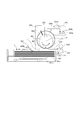
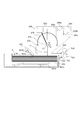
次に、図2を用いて本実施の形態に係るシート給送装置51の構成について説明する。既述したように、シート給送装置51は、カセット51aと、カセット51aに収納されたシートSを静電気により電気的に吸着しながら1枚ずつ給送するシート吸着分離給送部51bとを備えている。また、シート給送装置51は、カセット51aに昇降可能に設けられ、シートSが積載される中板301aを昇降させる昇降手段301と、シート吸着分離給送部51bにより給送されたシートSの通過を検知するシート先端検出センサ51cを備えている。
シート吸着分離給送部51bは、吸着部材400、駆動ローラ401、駆動手段203、電源ユニット205によって構成されている。吸着部材400は、可撓性で駆動ローラ401の外周長さよりも長い無端形状のものであり、吸着部材400の断面形状は自身の弾性力を以て略円形を保つようになっている。駆動ローラ401は、配置位置が固定の不図示の軸支持部材によって回転自在に軸支されており、カセット51aに積載された最上位シートSaの上面から所定の空隙Lrを以て配置されている。また、駆動ローラ401には、駆動手段203からの駆動力が駆動伝達手段を介して伝達される。なお、シート給送装置52に設けられたシート吸着分離給送部52bも、シート給送装置51のシート吸着分離給送部51bと同様の構成であるため、説明は省略する。
ここで、本実施の形態において、吸着部材400は、駆動ローラ401との間に隙間Gを設けて一部が、駆動ローラ401の固定部402に固定されている。言いかえれば、吸着部材400は、弛んだ状態で駆動ローラ401に支持されている。なお、吸着部材400の駆動ローラ401への固定は接着剤等で行っても良いし、不図示の固定部材と駆動ローラ401とで吸着部材400を挟み込むことにより行っても良い。なお、固定部材を使用して吸着部材400を固定する際には固定部材が吸着部材400表面から突出した状態になるが、この場合、固定部材により吸着部材400をシートとは接触しない部分で固定することにより、シート給送動作の弊害にはならないようにする。
昇降手段301は、中板301aの下方に回動可能に設けられたリフタ301bを備えており、リフタ301bの回動角度によって、中板301a及び中板301a上に積載された最上位シートSaの位置を変更する。シート先端検出センサ51cは、シート吸着分離給送部51bと引き抜きローラ対51d,51eとの間のシート搬送経路中に配置されている。そして、所定のタイミングでシート先端検出センサ51cがシートSを検出するか否かにより、シート給送の成否を検出する。本実施の形態では、シート先端検出センサ51cは非接触の反射式フォトセンサであり、検出対象にスポット光を照射し、その反射光量を測定して検出対象の有無を検出する。
なお、図2において、302は中板301aに積載されたシートSの上面位置を検知する紙面高さ検出手段である。この紙面高さ検出手段302は、中板301aの上方に配置されると共に、センサフラグ302aとフォトセンサ302bによって構成されている。センサフラグ302aは不図示の支持部に回転可能に支持されており、一端は最上位シートSaの上面と接触可能な位置に、他端はフォトセンサ302bを遮光可能な位置に配置されている。
ここで、最上位シートSaの上面が所定の高さに位置すると、センサフラグ302aが回転し、フォトセンサ302bが遮光される。なお、後述する図5に示す制御部70は、フォトセンサ302bの遮光状態を検出することにより、最上位シートSaの上面位置を検出する。そして、制御部70は、最上位シートSaの上面が紙面高さ検出手段302によって常に検出されるように昇降手段301の動作を制御し、中板301aの位置を最上位シートSaの上面高さが略一定となる位置に保つ。この結果、駆動ローラ401と、最上位シートSaの上面との空隙Lrも略一定に保たれる。
ここで、本実施の形態においては、吸着部材400にシートを吸着して搬送する際、シート同士が摺擦しないように、吸着部材400にシートを静電気により吸着した後、吸着部材400を弾性変形させながら上方に引き上げるようにしている。そして、このように吸着部材400を弾性変形させながら上方に引き上げることにより、シートを他のシートから分離する。
そこで、本実施の形態では、この吸着分離に必要なシート吸着力が得られる後述する図6の(a)に示すシート接触面積Mnが確保されるように、吸着部材400の長さが決定されている。
また、電源ユニット205は、第1電源である正電圧供給手段205a及び第2電源である負電圧供給手段205bと、それぞれの電圧供給を制御するスイッチ205c,205dを備えている。そして、電源ユニット205で発生した電圧は、駆動ローラ401を介して吸着部材400に供給され、これらの印加電圧によって吸着部材400にはシートSを引き付ける静電的な吸着力が発生する。
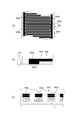
次に、図3を用いて、シート吸着分離搬送部51bが備えている吸着部材400の詳細構成ならびに、吸着部材400がシートSを吸着する吸着力の発生原理を説明する。図3は吸着部材400の構成を示した模式図である。図3の(a)は吸着部材400表面を、図3の(b)は吸着部材400の給電部断面を、図3の(c)は吸着部材400とシートSに働く静電吸着力の概念断面図をそれぞれ表している。
吸着部材400は、基層400c、正電極400a、ならびに負電極400bによって構成され、基層400cの内部に、櫛歯形状の正電極400aと、同様に櫛歯形状の負電極400bとが交互に配置されている。本実施の形態では、基層400cは体積抵抗108Ωcm以上の誘電体であるポリイミドであり、層厚は100μm程度である。また、正電極400aならびに負電極400bは体積抵抗106Ωcm以下の導電体であり、層厚10μm程度の銅を用いている。
吸着部材400の裏面には、正電極400aならびに他方の電極である負電極400bのそれぞれが露出している露出領域400d、400eが設けられている。正電極400aの露出領域400dには正電圧供給手段205aからの電圧が、負電極400bの露出領域400eには負電圧供給手段205bからの電圧がそれぞれ駆動ローラ201を介して供給される構成となっている。これにより、本実施例では、正電極400aならびに負電極400bがそれぞれ1kV程度の正負電圧となる。
電圧が印加された正電極400aならびに負電極400bによって、吸着部材400の表面近傍には不平等電界が形成される。吸着部材400をシートSに接近させると誘電体であるシートS表層には誘電分極が生じ、Maxwellの応力によって、吸着部材400とシートSとの間に静電吸着力が生じる。
また、駆動ローラ401は、図4に示すように、絶縁軸401cと、絶縁軸401cの両端部に取り付けられた導電部401a,401bとを備えている。なお、絶縁軸401cは、絶縁性の樹脂等で形成しても良いし、金属製の軸の表面に絶縁性のコートをして形成しても良い。導電部401a,401bは、絶縁軸401cに金属性の円筒形状のカバーを固定して形成しも良いし、絶縁軸401cの周囲に導電性物質をパターニングして形成しても良い。そして、導電部401a,401bには、それぞれ板ばね406a,406bが接触しており、この板ばね406a,406bには正電圧供給手段205a及び負電圧供給手段205bから正、負電圧がそれぞれ供給される。
また、図4において、400aは吸着部材400の正電極、400bは吸着部材400の負電極であり、400dは正電極400aが露出する露出領域、400eは負電極400bが露出する露出領域である。そして、吸着部材400は、露出領域400d,400eが導電部401a,401bと接触するように駆動ローラ401に固定されている。この構成により、正電圧供給手段205aで発生した正電圧は、板ばね406a、導電部401aを介して正電極400aに、負電圧供給手段205bで発生した負電圧は板ばね406b、導電部401bを介して負電極400bに供給される。
図5は、本実施の形態に係るシート給送装置51の制御ブロック図であり、図5において、70は制御部である。制御部70には、既述したシート先端検出センサ51c、紙面高さ検出手段302等の他、駆動手段203、正電圧供給手段205a、負電圧供給手段205b等が接続される。
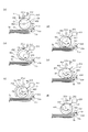
次に、図6を用いて、本実施の形態に係るシート吸着分離給送部51bによるシート給送動作について説明する。図6の(a)は、吸着部材400を給送動作の初期位置に配置する初期動作を示している。この動作のとき、例えば、既述した図5に示す制御部70は、シートSに対して吸着部材400を所定の空隙Lrを以て離間させる位置になるように、駆動ローラ401を停止させる。なお、本実施の形態において、駆動手段203はエンコーダを備えたステッピングモータであり、不図示のセンサがエンコーダのホームポジションを検知した位置が吸着部材400の給送動作の初期位置となる。
図6の(b)は接近動作を示しており、この動作のとき、制御部70は、駆動ローラ401を矢印F方向へ回転させる。ここで、本実施の形態において、吸着部材400の中心Cbが駆動ローラ401の回転中心Crから偏心している。このため、駆動ローラ401を矢印F方向へ回転させると、吸着部材400が最上位シートSaの上面に接近する。
図6の(c)は接触面積増大動作を示しており、この動作のとき、制御部70は、接近動作と同様に、駆動ローラ401を矢印F方向へ回転させることで、吸着部材400と最上位シートSaとの接触面積Mcを増大させている。なお、本実施の形態において、駆動手段203がステッピングモータであるため、初期動作からの回転角度をステッピングモータのステップ数で管理することで、接触面積Mnとなる位置を判断できる。図6の(d)は吸着動作を示している。この動作のとき、制御部70は、接触面積増大動作により接触面積をMnまで増大させた後、正電圧供給手段205a及び負電圧供給手段205bから吸着部材400に電圧を印加し始め、吸着部材400とシートSとの間に静電吸着力を働かせる。
図6の(e)は搬送動作を示しており、この動作のとき、制御部70は、既述した吸着動作の後にさらに駆動ローラ401を矢印F方向に回転し続ける。これにより、吸着部材400に吸着した最上位シートSaの先端部が矢印D方向に持ち上がり、下方のシートSbから分離する。なお、本実施の形態において、駆動ローラ401のシート給送方向下流には搬送ガイド303が設置されている。そして、この搬送ガイド303により、吸着部材400に吸着した最上位シートSaの、シートSaの剛性により吸着部材400から離間した先端部をガイドし、最上位シートSaを引き抜きローラ対51d,51eまで搬送する。
図6の(f)は、離間動作を示しており、この動作のとき、制御部70は、搬送されている最上位シートSaが引き抜きローラ対51d,51eで挟持された後、吸着部材400への電圧供給を止める。これにより、吸着部材400に吸着搬送されているシートSaは、挟持されている引き抜きローラ対51d,51eにより搬送される。この後、駆動ローラ401がさらに回転すると、吸着部材400は搬送されているシートSaから離間し、次のシートSbの搬送を待機する図6の(a)に示す初期状態になる。なお、シート先端検出センサ51cにてシートSaが検出されなかった場合は、シートSの給送動作にミスが生じたと判断し、再び接近動作から給送動作をやり直す。以上の6つの工程によって、カセット51aに積載された複数のシートSからシートが1枚だけ給送される。この6つの工程を繰り返し行えば、シートSを1枚ずつ、連続で給送可能である。
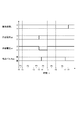
図7は、図6に示す初期動作、接近動作、接触面積増大動作、吸着動作、搬送動作及び離間動作のタイミングチャートである。ここでは、駆動ローラ401の搬送速度u、正電圧供給手段205aからの供給電圧vp、負電圧供給手段205bからの供給電圧vn、ならびにシート先端検出センサ51cの検出パルスpsを示している。図7において、P1で示す時刻T0からT1までの区間は初期動作区間であり、搬送速度uは0、供給電圧vp、供給電圧vnは0にそれぞれ設定されている。P2で示す時刻T1からT2までの区間は接近動作区間であり、搬送速度uはUに設定されている。
P3で示す時刻T2からT3までの区間は接触面積増大動作区間であり、時刻T1から継続して搬送速度uには速度Uが設定されている。時刻T3が吸着動作を行う時点であり、このとき、供給電圧vpには+V、供給電圧vnには-Vが設定される。P4で示す時刻T3からT5までの区間は搬送動作区間であり、継続して搬送速度uにはU、供給電圧vpには+V、供給電圧vnには-Vが設定されている。時刻T3の直後の時刻T4には検出パルスpsが出力される。そして、この時刻T4が所定の値の範囲に収まっているか否かにより制御部70は、給送リトライの判断を行う。
P5で示す時刻T5からT6までの区間は離間動作区間である。搬送速度uにはUが設定されているが、時刻T5で供給電圧vp及び供給電圧vnは再度0が設定され、時刻T6で搬送速度uには0が設定される。P6で示す時刻T6からT8までの区間は初期動作区間であり、次のシートSの給送に備える。なお、この初期動作区間P6でも、これまで吸着部材400に吸着搬送されていたシートSaは、下流に配置されている引き抜きローラ対51d,51eで搬送されている。このため、次のシートの給送を開始することができるのは、検出パルスpsの出力がなくなる時刻T7以降となる。この後、上記を繰り返せば連続したシート給送が行われる。
以上説明したように、本実施の形態においては、吸着部材400が、1つの駆動ローラ(回転部材)401の回転に同期して回転可能に設けられている。そして、吸着部材400の下方への弛み量を大きくすることで、積載されたシートを吸着部材400に吸着させた後、吸着部材400の下方への弛み量を小さくさせながら吸着部材400に吸着されたシートを給送する。このとき、駆動ローラ401が1回転する間に、吸着部材400は待機位置からシートを吸着して給送した後、吸着部材400は再び待機位置に戻る。
これにより、吸着部材400の位置を簡易的かつ正確に制御することができる。また、吸着部材400をシートに面接触してシートを吸着する吸着位置、撓みを解消しながら吸着したシートを下方のシートから分離する分離位置、吸着したシートが離間する離間位置に移動可能としている。さらに、この吸着部材400を回転させてシートを吸着し、吸着したシートを引き抜きローラ対51d,51eに受け渡した後、吸着部材400をシートから離れた位置(待機位置)で停止させるようにしている。これにより、吸着部材400を担持するフレームや、駆動手段、ローラ等を移動させることなく、シートを分離給送することができる。この結果、簡単な構成で、かつ低騒音で静電吸着によるシートの給送を安定して行うことができる。
これにより、吸着部材400の位置を簡易的かつ正確に制御することができる。また、吸着部材400をシートに面接触してシートを吸着する吸着位置、撓みを解消しながら吸着したシートを下方のシートから分離する分離位置、吸着したシートが離間する離間位置に移動可能としている。さらに、この吸着部材400を回転させてシートを吸着し、吸着したシートを引き抜きローラ対51d,51eに受け渡した後、吸着部材400をシートから離れた位置(待機位置)で停止させるようにしている。これにより、吸着部材400を担持するフレームや、駆動手段、ローラ等を移動させることなく、シートを分離給送することができる。この結果、簡単な構成で、かつ低騒音で静電吸着によるシートの給送を安定して行うことができる。
なお、本実施の形態では前記の動作工程によってシートSの分離給送を行っているが、本発明はこれに限定されるものではない。例えば、本実施の形態の初期動作では、駆動ローラ401を停止させているが、接近動作のタイミングに合うように離間動作から一定速度で駆動ローラを回転し続けても良い。また、本実施の形態の離間動作では、吸着部材400への電圧供給を停止して吸着部材400とシートSを離間させているが、電圧供給を継続して吸着部材400でシートSを搬送しても良い。
さらに、本実施の形態では、既述したような構成にて吸着部材400とシートSとの間に静電吸着力を生じさせたが、本実施の形態はこれに限定されるものではない。例えば、正電極400a及び負電極400bは櫛歯形状で無くとも良く、シートSとの間に電界が形成され、シートSを誘電分極させることができる一様電極のような形状でも良い。
次に、本発明の第2の実施の形態について説明する。図8は、本実施の形態に係るシート給送装置の構成を説明する図である。なお、図8において、既述した図2と同一符号は、同一又は相当部分を示している。
図8において、407は、駆動ローラ401と吸着部材400の間に設けられた弾性部材である円柱状のスポンジ部材であり、このスポンジ部材407は駆動ローラ401の外周に偏心して固定されている。また、スポンジ部材407の外周には無端状の吸着部材400が固定されている。
そして、本実施の形態のようにスポンジ部材407の外周に吸着部材400を固定することにより、吸着部材400の固定を、より確実かつ簡便に行うことが可能となり、低コスト化を図ることができる。また、吸着部材400の駆動ローラ側(回転部材側)への変形を防ぐことができる。なお、本実施の形態において、スポンジ部材407の外周に無端状の吸着部材400を固定する構成としたが、これに限定されるのではない。例えば、有端状の吸着部材をスポンジ部材の一部に固定しても良いし、スポンジ部材の表面に吸着部材と同様の機能を有する電極を配置しても良い。
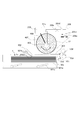
次に、本発明の第3の実施の形態について説明する。図9は、本実施の形態に係るシート給送装置の構成を説明する図である。なお、図9において、既述した図2と同一符号は、同一又は相当部分を示している。
図9において、450は、内部に電極を持たない樹脂製の吸着部材である。251cは、吸着部材450の上方に設けられ、吸着部材450に上方から圧接する電圧印加部材である帯電ローラである。この帯電ローラ251cは配置位置が固定の不図示の軸支持部材によって回転自在に軸支されており、吸着部材450の移動に伴って従動回転する。この帯電ローラ251cには交流電源252が接続されており、吸着部材450の表面は、帯電ローラ251cによる接触帯電によって電荷が付与され、この付与された電荷によってシートSを引き付ける静電的な吸着力が発生する。
次に、図10を用いて吸着部材450の詳細構成及び吸着部材450がシートSを吸着する吸着力の発生原理を説明する。図10の(a)は吸着部材450の斜視図であり、図10の(b)は吸着部材450の断面をそれぞれ表している。
吸着部材450は、単層構造の樹脂製の部材であり、体積抵抗108Ωcm以上の誘電体である。そして、吸着部材450の表面に押圧された帯電ローラ251cから交番電圧が印加される。これにより、吸着部材450の表面には図10の(a)に示すように、交流電源252の周波数と、吸着部材450の表面移動速度とに応じた間隔で、正極性に帯電された領域と負極性に帯電された領域とが縞状に形成される。この交互に縞状に形成された正負の帯電領域によって、吸着部材450の表面近傍には不平等電界が形成される。そして、このように不平等電界が形成された吸着部材450をシートSに接近させると誘電体であるシート表層には誘電分極が生じ、Maxwellの応力によって、吸着部材450とシートSとの間に静電吸着力が生じる。
次に、本実施の形態に係るシート吸着分離給送部51bのシート分離給送動作について説明する。図11は、シート吸着分離給送部51bによってシートSが給送される動作を時系列に表現した模式図である。
図11の(a)は吸着部材450を給送動作初期位置に配置する初期動作を示している。この動作のとき、既述した図5に示す制御部70は、吸着部材450が帯電ローラ251cに対して所定の空隙Lcを以て離間し、かつ、シートSに対して吸着部材450を所定の空隙Lbを以て離間する初期位置になるように、駆動ローラ401を停止させる。
図11の(b)は、吸着部材450を帯電ローラ251cと接触させて、交流電源252からの交番電圧により吸着部材450表面を帯電させる帯電動作を示しており、この動作のとき、制御部70は、駆動ローラ401を矢印F方向へ回転させる。ここで、吸着部材450の中心Cbが駆動ローラ401の回転中心Crから偏心しているため、初期状態から駆動ローラ401を回転させると、吸着部材450が帯電ローラ251cと接触し始める。そして、駆動ローラ401を回転させながら交番電圧を印加することで、吸着部材450には正極性と負極性とが交互に帯電された帯電領域Chが形成される。
図11の(c)は、吸着部材450の表面に形成された帯電領域Chを最上位シートSaの上面に対して接近させる接近動作を示しており、この動作のとき、制御部70は、引き続き駆動ローラ401を矢印F方向へ回転させる。そして、このように駆動ローラ401を回転させると、吸着部材450の中心Cbが駆動ローラ401の回転中心Crから偏心しているため、吸着部材450の表面が最上位シートSaの上面に接近する。
図11の(d)は、接近動作を継続させて吸着部材450の表面と最上位シートSaとを面接触させ、なおかつ、接触面積Mcを増大させる接触面積増大動作を示している。この動作のとき、制御部70は、接近動作と同様に、駆動ローラ401を矢印F方向へ回転させる。これにより、吸着部材450の帯電領域Chが最上位シートSaに接触し、吸着部材450に最上位シートSaが吸着される。さらに駆動ローラ401が回転すると、吸着部材450の帯電領域Chと最上位シートSaとの接触面積Mcが増大していく。
図11の(e)は、既述した接触面積増大動作により接触面積Mnとなった時に、吸着部材450の帯電領域Chに吸着されたシートSaを、積載された次位のシートSbと分離させながら引き抜きローラ対51d,51eまで搬送する搬送動作を示している。なお、この接触面積Mnは、吸着部材450に吸着された最上位シートSaを吸着部材450により搬送する際、吸着部材450の搬送力が最上位シートSaに働く搬送抵抗に打ち勝つ搬送力になるときの面積である。そして、このように接触面積がMnになった時点で、最上位シートSaが引き抜きローラ対51d,51eに向かって搬送され始める。
図11の(f)は、最上位シートSaが引き抜きローラ対51d,51eで挟持された後、搬送されている最上位シートSaを吸着部材450から離間させる離間動作を示している。シートSaが引き抜きローラ対51d,51eで挟持されると、吸着部材450の帯電領域Chは最上位シートSaと接触することがなくなるため、吸着部材450の吸着力が働かなくなる。そして、吸着部材450の吸着力が働かなくなると、搬送されている最上位シートSaは挟持されている引き抜きローラ対51d,51eにより搬送される。
この後、駆動ローラ401がさらに矢印F方向に回転し続けると、吸着部材450は、既述した図11の(a)に示すように搬送されているシートSaから離間した位置となり、次のシートSbの搬送を待機する初期状態に戻る。なお、シート先端検出センサ51cにてシートSaが検出されなかった場合は、シートSの給送動作にミスが生じたと判断し、再び接近動作から給送動作をやり直す。以上の6つの工程によって、カセット51aに積載された複数のシートSからシートが1枚だけ給送される。この6つの工程を繰り返し行えば、シートSを1枚ずつ、連続で給送可能である。
図12は、図11に示す初期動作、帯電動作、接近動作、接触面積増大動作、搬送動作及び離間動作のタイミングチャートである。ここでは、駆動ローラ401の搬送速度u、交流電源252からの供給電圧v、ならびにシート先端検出センサ51cの検出パルスpsを時系列に表した図である。図12において、P1で示す時刻T0からT1までの区間は初期動作区間であり、このとき搬送速度uには0、供給電圧vには0がそれぞれ設定されている。P2で示す時刻T1からT2までの区間は帯電動作区間であり、搬送速度uにはUが、供給電圧には±Vの交番電圧が設定される。
P3で示す時刻T2からT3までの区間は接近動作区間であり、時刻T1から継続して搬送速度uには速度Uが設定され、時刻T2で供給電圧vは再度0に設定される。P4で示す時刻T3からT4までの区間は接触面積増大動作区間であり、継続して搬送速度uには速度Uが設定されている。P5で示す時刻T4からT6までの区間は搬送動作区間であり、継続して搬送速度uには速度Uが設定されている。時刻T4の直後の時刻T5には検出パルスpsが出力される。また、時刻T5が所定の値の範囲に収まっているか否かで、制御部70は給送リトライの判断を行う。
P6で示す時刻T6からT7までの区間は離間動作区間である。搬送速度uにはUが設定されているが、時刻T7で搬送速度uには0が設定されるようになる。P7で示す時刻T7からT9までの区間は初期動作区間であり、次のシートSの給送に備える。なお、この初期動作区間P7でもシートSaは、引き抜きローラ対51d,51eで搬送されている。このため、次のシートの給送を開始することができるのは、検出パルスpsの出力がなくなる時刻T8以降となる。この後、上記を繰り返せば連続したシート給送が行われる。
以上説明したように、本実施の形態においては、帯電ローラ251cによって吸着部材表層を外部から帯電させることで、シート吸着力を得ることができる。この結果、吸着部材内部に電極を配置することなく、吸着部材450を帯電させることができるので、吸着部材450の構成を単純化することができ、低コスト化を図ることができる。
なお、本実施の形態では上記の6工程からなる給送動作を行ってシートSの分離給送を行っているが、本発明はこれに限定されるものではない。また、帯電ローラ251cに直流電流を接続して、吸着部材450に正負交互の帯電領域を形成せずに全面同極性の帯電領域を形成してもよい。その場合、単位面積あたりの静電吸着力は小さくなるものの、より簡便に静電吸着力を生じさせることができる。
次に、本発明の第4の実施の形態について説明する。図13は、本実施の形態に係るシート給送装置の構成を説明する図である。なお、図13において、既述した図2と同一符号は、同一又は相当部分を示している。
図13において、270は吸着部材、271は駆動ローラである。駆動ローラ271は、配置位置が固定の不図示の軸支持部材によって回転自在に軸支されており、カセット51aに積載された最上位シートSaの上面から所定の空隙Lrを以て配置されている。また、駆動ローラ271には、駆動手段203からの駆動力が駆動伝達手段を介して伝達されている。
さらに、駆動ローラ271には吸着部材270を固定するための固定部材272が固定されている。なお、本実施の形態において、吸着部材270は、駆動ローラ271の周面の長さよりも長い有端形状の可撓性を有する部材であり、吸着部材270の両端は、自身の弾性力を以て半円弧より長い略円弧形状を描くように固定部材272に固定されている。
そして、本実施の形態のように吸着部材270を有端形状とすることにより、既述した第1の実施の形態と同様の効果を得ることができると共に吸着部材270の長さを短くすることにより、低コスト化を図ることができる。
なお、これまで説明した実施の形態では静電吸着力によってシートSを吸着部材に吸着させているが、本発明はこれに限定されるものではない。例えば、吸着部材上にサブミクロンオーダーの微細な繊維構造を形成し、シートSとの間に働く分子間引力によって吸着させてもよい。
51,52…シート給送装置
51a,52a…カセット
51b,52b…シート吸着分離給送部
51c…シート先端検出センサ
51d,51e…引き抜きローラ対
55…画像形成部
70…制御部
100…画像形成装置
100A…画像形成装置本体
201…駆動ローラ
203…駆動手段
205…電源ユニット
205a…正電圧供給手段
205b…負電圧供給手段
252…交流電源
270…吸着部材
271…駆動ローラ
272…固定部材
400…吸着部材
400a…正電極
400b…負電極
401…駆動ローラ
401a,401b…導電部
402…固定部
407…スポンジ部材
450…吸着部材
G…隙間
Mn…シート接触面積
S…シート
Sa…最上位シート
51a,52a…カセット
51b,52b…シート吸着分離給送部
51c…シート先端検出センサ
51d,51e…引き抜きローラ対
55…画像形成部
70…制御部
100…画像形成装置
100A…画像形成装置本体
201…駆動ローラ
203…駆動手段
205…電源ユニット
205a…正電圧供給手段
205b…負電圧供給手段
252…交流電源
270…吸着部材
271…駆動ローラ
272…固定部材
400…吸着部材
400a…正電極
400b…負電極
401…駆動ローラ
401a,401b…導電部
402…固定部
407…スポンジ部材
450…吸着部材
G…隙間
Mn…シート接触面積
S…シート
Sa…最上位シート
Claims (12)
- シートが積載される積載手段と、
前記積載手段の上方に配置された回転部材と、
前記回転部材の回転に同期して移動可能に設けられ、前記積載手段に積載されたシートを電気的に吸着する吸着部材と、
前記回転部材を回転させる駆動手段と、
前記駆動手段を制御する制御手段と、を有し、
前記制御手段は、前記吸着部材の下方への弛み量を大きくすることで前記積載手段に積載されたシートを前記吸着部材に吸着させた後、前記吸着部材の下方への弛み量を小さくさせながら前記吸着部材に吸着されたシートを給送するシート給送装置において、
前記制御手段は、前記回転部材を1回転させることで、前記吸着部材を待機位置から移動させてシートを吸着して給送した後、前記吸着部材を前記待機位置に移動させることを特徴とするシート給送装置。 - 前記吸着部材は、弛んだ状態で前記回転部材に支持されていることを特徴とする請求項1に記載のシート給送装置。
- 前記吸着部材は無端形状の部材であり、前記回転部材に一部が固定されていることを特徴とする請求項1または2に記載のシート給送装置。
- 前記吸着部材は、前記回転部材の周面に取り付けられた弾性部材を介して前記回転部材に支持されることを特徴とする請求項1または2に記載のシート給送装置。
- 前記吸着部材は有端形状の部材であり、両端を前記回転部材に取り付けられた固定部材に固定されて円弧形状を形成しながら前記回転部材に支持されることを特徴とする請求項1または2記載のシート給送装置。
- 前記吸着部材に電圧を印加して静電気によりシートを吸着する吸着力を付与するための電源を有することを特徴とする請求項1乃至5のいずれか1項に記載のシート給送装置。
- 前記吸着部材には2つの電極が配され、
前記電源は、前記2つの電極の一方に正の電圧を印加する第1電源と、前記2つの電極の他方に負の電圧を印加する第2電源とを備えていることを特徴とする請求項6に記載のシート給送装置。 - 前記吸着部材と前記電源の間に設けられ、前記吸着部材がシートに接触する前に前記吸着部材に当接して前記吸着部材に前記電源からの電圧を印加する電圧印加部材を備えたことを特徴とする請求項6に記載のシート給送装置。
- 前記電源は交流電源であることを特徴とする請求項8記載のシート給送装置。
- 前記吸着部材が弛みを解消する際の前記静電気による吸着力の大きさが、シートの剛性により、シートが前記吸着部材から離間するような大きさに設定されていることを特徴とする請求項1乃至9のいずれか1項に記載のシート給送装置。
- 前記吸着部材は可撓性を有し、前記積載手段に積載されたシートから離れた待機位置、前記積載手段に積載されたシートを吸着する吸着位置、吸着したシートを上方に移動させて下方のシートから分離させる分離位置、吸着したシートが前記吸着部材から離間する離間位置に移動可能に設けられていることを特徴とする請求項1乃至10のいずれか1項に記載のシート給送装置。
- シートに画像を形成する画像形成部と、
前記画像形成部にシートを給送する請求項1乃至11のいずれか1項に記載のシート給送装置と、を備えたことを特徴とする画像形成装置。
Priority Applications (1)
| Application Number | Priority Date | Filing Date | Title |
|---|---|---|---|
| US14/777,622 US20160272442A1 (en) | 2013-04-12 | 2014-04-10 | Sheet feeding device and image forming apparatus |
Applications Claiming Priority (4)
| Application Number | Priority Date | Filing Date | Title |
|---|---|---|---|
| JP2013083584 | 2013-04-12 | ||
| JP2013-083584 | 2013-04-12 | ||
| JP2014056024A JP2014218371A (ja) | 2013-04-12 | 2014-03-19 | シート給送装置及び画像形成装置 |
| JP2014-056024 | 2014-03-19 |
Related Child Applications (1)
| Application Number | Title | Priority Date | Filing Date |
|---|---|---|---|
| US14/777,622 Continuation US20160272442A1 (en) | 2013-04-12 | 2014-04-10 | Sheet feeding device and image forming apparatus |
Publications (1)
| Publication Number | Publication Date |
|---|---|
| WO2014168207A1 true WO2014168207A1 (ja) | 2014-10-16 |
Family
ID=51689611
Family Applications (1)
| Application Number | Title | Priority Date | Filing Date |
|---|---|---|---|
| PCT/JP2014/060410 Ceased WO2014168207A1 (ja) | 2013-04-12 | 2014-04-10 | シート給送装置及び画像形成装置 |
Country Status (3)
| Country | Link |
|---|---|
| US (1) | US20160272442A1 (ja) |
| JP (1) | JP2014218371A (ja) |
| WO (1) | WO2014168207A1 (ja) |
Cited By (1)
| Publication number | Priority date | Publication date | Assignee | Title |
|---|---|---|---|---|
| CN105480515A (zh) * | 2015-12-29 | 2016-04-13 | 陕西科技大学 | 一种基于静电吸附原理的取标装置及方法 |
Families Citing this family (2)
| Publication number | Priority date | Publication date | Assignee | Title |
|---|---|---|---|---|
| JP2016008102A (ja) * | 2014-06-24 | 2016-01-18 | キヤノン株式会社 | シート給送装置及び画像形成装置 |
| CN106945880A (zh) * | 2017-04-26 | 2017-07-14 | 河南科伦药业有限公司 | 一种自动投放纸箱内垫纸/垫板的装置 |
Citations (5)
| Publication number | Priority date | Publication date | Assignee | Title |
|---|---|---|---|---|
| JPS58202230A (ja) * | 1982-05-18 | 1983-11-25 | Fuji Xerox Co Ltd | 給紙装置 |
| JPS59112839U (ja) * | 1983-01-19 | 1984-07-30 | 富士ゼロックス株式会社 | 用紙送出装置 |
| JPH05139548A (ja) * | 1991-11-15 | 1993-06-08 | Ricoh Co Ltd | 給紙装置およびその装置を用いる給紙方法 |
| JPH06255823A (ja) * | 1993-02-26 | 1994-09-13 | Nec Corp | 搬送装置 |
| JP2012140224A (ja) * | 2011-01-05 | 2012-07-26 | Ricoh Co Ltd | シート材給送装置、及び画像形成装置 |
-
2014
- 2014-03-19 JP JP2014056024A patent/JP2014218371A/ja active Pending
- 2014-04-10 WO PCT/JP2014/060410 patent/WO2014168207A1/ja not_active Ceased
- 2014-04-10 US US14/777,622 patent/US20160272442A1/en not_active Abandoned
Patent Citations (5)
| Publication number | Priority date | Publication date | Assignee | Title |
|---|---|---|---|---|
| JPS58202230A (ja) * | 1982-05-18 | 1983-11-25 | Fuji Xerox Co Ltd | 給紙装置 |
| JPS59112839U (ja) * | 1983-01-19 | 1984-07-30 | 富士ゼロックス株式会社 | 用紙送出装置 |
| JPH05139548A (ja) * | 1991-11-15 | 1993-06-08 | Ricoh Co Ltd | 給紙装置およびその装置を用いる給紙方法 |
| JPH06255823A (ja) * | 1993-02-26 | 1994-09-13 | Nec Corp | 搬送装置 |
| JP2012140224A (ja) * | 2011-01-05 | 2012-07-26 | Ricoh Co Ltd | シート材給送装置、及び画像形成装置 |
Cited By (1)
| Publication number | Priority date | Publication date | Assignee | Title |
|---|---|---|---|---|
| CN105480515A (zh) * | 2015-12-29 | 2016-04-13 | 陕西科技大学 | 一种基于静电吸附原理的取标装置及方法 |
Also Published As
| Publication number | Publication date |
|---|---|
| US20160272442A1 (en) | 2016-09-22 |
| JP2014218371A (ja) | 2014-11-20 |
Similar Documents
| Publication | Publication Date | Title |
|---|---|---|
| US8480073B1 (en) | Sheet feeder and image forming apparatus incorporating same | |
| JP5375327B2 (ja) | シート分離給紙装置および画像形成装置 | |
| US20160289022A1 (en) | Sheet feeding device and image forming apparatus | |
| JP6347634B2 (ja) | シート給送装置及び画像形成装置 | |
| WO2014168207A1 (ja) | シート給送装置及び画像形成装置 | |
| WO2014168208A1 (ja) | シート給送装置及び画像形成装置 | |
| JP2016124705A (ja) | シート給送装置及び画像形成装置 | |
| US9244419B2 (en) | Sheet compression apparatus and image forming apparatus | |
| JP2003160249A (ja) | シート搬送装置及び画像処理装置 | |
| JP5910923B2 (ja) | シート搬送装置及び画像形成装置 | |
| JP6478803B2 (ja) | シート給送装置及び画像形成装置 | |
| JP5429634B2 (ja) | シート搬送装置および画像形成装置 | |
| JP2018177413A (ja) | シート給送装置及び画像形成装置 | |
| JP2012162346A (ja) | シート材給送装置、及び画像形成装置 | |
| JP2019104608A (ja) | 静電吸着ベルト、シート給送装置及び画像形成装置 | |
| JP2016044028A (ja) | シート給送装置及び画像形成装置 | |
| JP2016008102A (ja) | シート給送装置及び画像形成装置 | |
| JP2016013878A (ja) | シート給送装置及び画像形成装置 | |
| JP2011042428A (ja) | シート材分離給送装置および画像形成装置 | |
| JP2017019650A (ja) | シート給送装置及び画像形成装置。 | |
| JP2010037028A (ja) | 用紙分離装置、用紙搬送装置及び画像形成装置 | |
| JP2014051333A (ja) | シート分離搬送装置、及び画像形成装置 | |
| JP2016034868A (ja) | シート給送装置及び画像形成装置 | |
| JP2019128401A (ja) | ベルト装置、及び、画像形成装置 | |
| JP2018116125A (ja) | 転写装置および画像形成装置 |
Legal Events
| Date | Code | Title | Description |
|---|---|---|---|
| 121 | Ep: the epo has been informed by wipo that ep was designated in this application |
Ref document number: 14783046 Country of ref document: EP Kind code of ref document: A1 |
|
| WWE | Wipo information: entry into national phase |
Ref document number: 14777622 Country of ref document: US |
|
| NENP | Non-entry into the national phase |
Ref country code: DE |
|
| 122 | Ep: pct application non-entry in european phase |
Ref document number: 14783046 Country of ref document: EP Kind code of ref document: A1 |