WO2014168156A1 - スプリンクラー消火装置 - Google Patents
スプリンクラー消火装置 Download PDFInfo
- Publication number
- WO2014168156A1 WO2014168156A1 PCT/JP2014/060226 JP2014060226W WO2014168156A1 WO 2014168156 A1 WO2014168156 A1 WO 2014168156A1 JP 2014060226 W JP2014060226 W JP 2014060226W WO 2014168156 A1 WO2014168156 A1 WO 2014168156A1
- Authority
- WO
- WIPO (PCT)
- Prior art keywords
- fire extinguishing
- sprinkler
- main tank
- tank
- extinguishing device
- Prior art date
Links
Images


Classifications
-
- A—HUMAN NECESSITIES
- A62—LIFE-SAVING; FIRE-FIGHTING
- A62C—FIRE-FIGHTING
- A62C35/00—Permanently-installed equipment
- A62C35/02—Permanently-installed equipment with containers for delivering the extinguishing substance
- A62C35/11—Permanently-installed equipment with containers for delivering the extinguishing substance controlled by a signal from the danger zone
- A62C35/13—Permanently-installed equipment with containers for delivering the extinguishing substance controlled by a signal from the danger zone with a finite supply of extinguishing material
-
- A—HUMAN NECESSITIES
- A62—LIFE-SAVING; FIRE-FIGHTING
- A62C—FIRE-FIGHTING
- A62C37/00—Control of fire-fighting equipment
- A62C37/08—Control of fire-fighting equipment comprising an outlet device containing a sensor, or itself being the sensor, i.e. self-contained sprinklers
- A62C37/10—Releasing means, e.g. electrically released
- A62C37/11—Releasing means, e.g. electrically released heat-sensitive
- A62C37/12—Releasing means, e.g. electrically released heat-sensitive with fusible links
-
- A—HUMAN NECESSITIES
- A62—LIFE-SAVING; FIRE-FIGHTING
- A62C—FIRE-FIGHTING
- A62C35/00—Permanently-installed equipment
- A62C35/02—Permanently-installed equipment with containers for delivering the extinguishing substance
- A62C35/10—Containers destroyed or opened by flames or heat
Definitions
- the present invention relates to a sprinkler fire extinguishing device that is provided on the ceiling of a building such as a building or a house and automatically discharges water when a fire (including a small fire such as ignition of tempura oil) is detected. Is.
- a sprinkler head installed on the ceiling of a building is connected to a water tank or a water system provided on the ground or underground by a metal pipe,
- a temperature sensor provided in the vicinity of a sprinkler head is known which is electrically connected to a water supply pump.
- the water supply pump draws up water in the water tank and discharges it from the sprinkler head.
- the object of the present invention is to solve the problems of the above-mentioned conventional sprinkler fire extinguishing apparatus, has a simple and compact structure, can be constructed inexpensively and easily, and can be easily built into ordinary houses and existing houses. Another object is to provide a sprinkler fire extinguishing device that can be installed and is easy to maintain. In addition, in order to demonstrate a high fire extinguishing capability with a small amount of fire extinguishing agent, to provide a sprinkler fire extinguishing device that does not cause enormous damage due to the fire extinguishing agent even if it is accidentally activated during a non-fire. is there.
- the invention described in claim 1 includes a main tank storing a fire extinguishing agent and a sensor for detecting temperature, and when the sensor detects a predetermined temperature, A sprinkler fire extinguishing apparatus that discharges a fire extinguishing agent to the outside.
- the invention described in claim 2 is the invention described in claim 1, wherein the sensor is provided in a sprinkler head, the main tank is connected to the sprinkler head, and the sensor is a predetermined sensor. When the temperature is detected, the fire extinguisher in the main tank is discharged from the sprinkler head to the outside.
- the invention described in claim 3 is the invention described in claim 1 or claim 2, further comprising: a sub tank filled with compressed gas; and a trigger for opening the sub tank.
- the trigger is interlocked to open the sub tank, and the compressed gas in the sub tank is caused to flow into the main tank, thereby releasing the fire extinguishing agent in the main tank. It is.
- the invention described in claim 4 is the invention described in any one of claims 1 to 3, wherein the trigger has a biasing means and a pin member, and the sensor detects a predetermined temperature. Then, the compressed gas in the sub tank is caused to flow into the main tank by piercing the pin member into the sub tank by the biasing means.
- the sprinkler fire extinguishing apparatus according to claim 1 can be constructed inexpensively and easily because there is no need to provide a long pipe connecting the water tank or the like and the sprinkler head unlike the conventional sprinkler fire extinguishing apparatus. In addition, even when it is not used for a long period of time, it does not occur that piping or the like rusts, so that maintenance is easy. In addition, any type of fire can be effectively extinguished.
- the sprinkler fire extinguishing apparatus can detect a fire sensitively because a fire extinguisher in the main tank is released from the sprinkler head when a sensor provided in the sprinkler head detects a predetermined temperature. It can be extinguished very efficiently.
- the sprinkler fire extinguishing apparatus can discharge the fire extinguishing agent in the main tank from the sprinkler head within a short time by using the compressed gas in the sub tank, it is effective for the situation where the fire spreads. Can be prevented.
- the sprinkler fire extinguishing apparatus can effectively prevent a situation where the trigger is reliably operated and a fire spreads in the event of a fire.
- FIG. It is explanatory drawing which shows the concept of the sprinkler fire extinguishing apparatus of Example 1.
- FIG. It is explanatory drawing which shows the concept of the sprinkler fire extinguishing apparatus of Example 3.
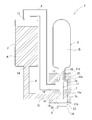
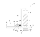
- FIG. 1 shows the concept of a sprinkler fire extinguishing device.
- the sprinkler fire extinguishing device 1 includes a main tank 2, a sub tank 3, a plug member 11 that functions as a trigger, a housing 7 that houses the plug member 11, and a temperature sensor.
- the main tank 2 is formed in a hollow cylindrical shape from metal (for example, aluminum) and has a volume of about 3.0 liters.
- An inlet 13 is provided at the upper end of the main tank 2, and the tip of a metal pipe 8 is connected to the inlet 13.
- a discharge port 14 is provided at the lower end, and a base end of a metal pipe 9 is connected to the discharge port 14.
- the main tank 2 is filled with about 2.0 liters of a fire extinguisher A (for example, a phosphate fire extinguisher in which a polysaccharide, phosphate, or the like is added to a surfactant). .
- a fire extinguisher A for example, a phosphate fire extinguisher in which a polysaccharide, phosphate, or the like is added to a surfactant.
- the sub tank 3 is formed of a metal (for example, aluminum) into a hollow cylindrical shape, and has a volume of about 500 ml (milliliter). Further, at the lower end of the sub-tank 3, a cylindrical discharge pipe 10 is formed to have a smaller diameter than other parts, and a discharge port 12 is provided at the tip (lower end) of the discharge pipe 10. Yes. The tip of the discharge pipe 10 is connected to the housing 7. The sub tank 3 is filled with compressed gas G (CO 2 ).
- CO 2 compressed gas
- the housing 7 is formed of a heat-resistant synthetic resin so as to have a substantially cylindrical outer shape.
- the internal space is partitioned into two chambers, a first chamber 7a and a second chamber 7b, by the partition plate 15.
- An insertion hole 16 is formed substantially at the center of the partition plate 15, and an axial center of a plug member 11 described later is inserted into the insertion hole 16.
- the first chamber 7a is provided with a gas inflow hole 17 and a gas discharge hole 18, which are connected to the discharge pipe 10 of the sub tank 3 and the base end of the pipe 8, respectively.
- the second chamber 7 b is provided with a fire extinguishing agent inflow hole 19 and a fire extinguishing agent discharge hole 20, and the extinguishing agent inflow hole 19 is connected to the tip of the pipe 9.
- the plug member 11 is formed in a substantially rod shape with metal, and a thick flange-shaped plug body 11b for closing the extinguishing agent discharge hole 20 of the housing 7 is provided at the lower end of the cylindrical shaft body 11a. It has been.
- the plug 11b is engaged with an outer plate 24 (described later) of the sprinkler head 6.
- a flange body 11c for closing the lower end of the gas inflow hole 17 of the housing 7 (the tip of the discharge pipe 10 of the sub tank 3) is provided at the upper end of the shaft body 11a, and above the flange body 11c.
- a protrusion 11d is formed.
- the protrusion 11d has a pointed tip, and an inclined surface is formed on one side (the side where the gas discharge port 18 is installed).
- the plug member 11 presses the flange body 11c against the lower end of the discharge pipe 10 of the sub tank 3, closes the discharge port 12 of the discharge pipe 10 with the projection 11d, and discharges the fire extinguishing agent of the housing 7 with the plug body 11b. It is installed in the housing 7 so that the hole 20 is closed.
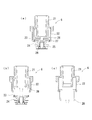
- the sprinkler head 6 includes a main body 21, a frame 22, an inner plate 23, an outer plate 24, heat sensitive bodies 25, 25..., A fusible body 26, and a ring body 27.
- the deflector 28 and the like are assembled.
- the fusible body 26 functions as a temperature sensor, is formed of solder (an alloy mainly composed of lead and tin), and melts at a predetermined temperature (about 96 ° C.). .
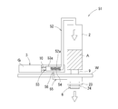
- the sprinkler fire extinguishing apparatus 1 configured as described above is installed and used in a building with the housing 7 placed on the upper side of the ceiling board and the sprinkler head 6 exposed from the ceiling board.
- the fusible body 26 as a temperature sensor melts at a predetermined temperature.
- the inner plate 23 and the outer plate 24 fall together as shown in FIG.
- the plug member 11 is pulled downward, so that the projection 11d of the plug member becomes the discharge pipe 10 of the sub tank 3. Since it falls off from the discharge port 12, the discharge port 12 is opened.
- the compressed gas G (CO 2 gas) in the sub-tank 3 is ejected at once and flows into the main tank through the pipe 8. Therefore, the extinguishing agent A in the main tank 2 is pressurized downward, and the pressure propagates to the second chamber 7b of the housing, so that the extinguishing agent A is rapidly (rapidly) from the extinguishing agent discharge hole 20 of the housing 7. Squirt.
- the deflector 28 (not shown) is lowered from the inside of the frame 22 as described above.
- the fire extinguishing agent A ejected from 20 hits the deflector 28 and diffuses and falls in all directions. Such a series of operations can effectively suppress the fire.
- the sprinkler fire extinguishing apparatus 1 includes the main tank 2 storing the fire extinguishing agent A, and the sprinkler head 6 connected to the main tank 2 and having a temperature sensor (the fusible body 26 of the sprinkler head 6).
- the temperature sensor detects a predetermined temperature (that is, when the fusible body 26 melts)
- the fire extinguishing agent A in the main tank 2 is released from the sprinkler head 6 to the outside.
- the sprinkler fire extinguishing apparatus 1 does not need to be provided with a long pipe connecting the water tank or the like and the sprinkler head unlike the conventional sprinkler fire extinguishing apparatus, and can be constructed inexpensively and easily. Moreover, even when the pipe 8 and the pipe 9 are not used for a long period of time, maintenance is easy because the pipe 8 and the pipe 9 are not easily rusted.
- the sprinkler fire extinguishing apparatus 1 includes a sub tank 3 filled with the compressed gas G and a trigger (plug member 11) for opening the sub tank 3.
- the trigger is Since the subtank 3 is opened in conjunction with the compressed gas G in the subtank 3 and flows into the main tank 2, the fire extinguishing agent A in the main tank 2 flows down to the sprinkler head 6. Since the fire extinguishing agent A in the main tank 2 can be released from the sprinkler head 6 within a short time by using the compressed gas G, it is possible to effectively prevent the situation where the fire spreads.
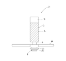
- FIG. 4 shows the concept of the sprinkler fire extinguishing device of the second embodiment.
- the sprinkler fire extinguishing device 31 is composed of the main tank 2, the sprinkler head 6 having a temperature sensor, the piping 9, and the like. And in the main tank 2, like the sprinkler fire extinguishing apparatus 1 of Example 1, while being filled with the fire extinguisher A, the compressed gas G was also filled and the fire extinguisher A was pressurized below. It is in a state.
- the main tank 2 is directly connected to the sprinkler head 6 by a metal pipe 9.
- the sprinkler fire extinguishing device 31 of the second embodiment is inexpensive and easy because it is not necessary to provide a long pipe for connecting a water tank or the like and the sprinkler head unlike the conventional sprinkler fire extinguishing device 1 as in the case of the sprinkler fire extinguishing device 1 of the first embodiment. Can be built. In addition, even when the pipe 9 is not used for a long period of time, maintenance is easy because the pipe 9 and the like are not easily rusted. Moreover, since the fire extinguisher A can be discharged from the sprinkler head 6 within a short time by using the compressed gas G in the main tank 2, it is possible to effectively prevent a fire from spreading.
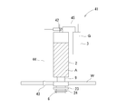
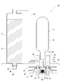
- FIG. 5 shows the concept of the sprinkler fire extinguishing device of the third embodiment.
- the sprinkler fire extinguishing device 41 includes a main tank 2, a sub tank 3, a valve (solenoid valve) 42 functioning as a trigger, and a sprinkler head having a temperature sensor. 6, a pipe 9, a second temperature sensor (fuse) 43, a signal line 44, a pipe 45, and the like.
- the structure of the main tank 2, the sub tank 3 and the sprinkler head 6 is the same as that of the sprinkler fire extinguishing device 1 of the first embodiment.
- the main tank 2 is filled with the fire extinguisher A, and the sub tank 3 is compressed. Gas G is filled.
- the main tank 2 is directly connected to the sprinkler head 6 through a metal pipe 9 as in the case of the sprinkler fire extinguishing device 31 of the second embodiment.
- a valve (electromagnetic valve) 42 is provided in the pipe 45 connecting the sub tank 3 and the main tank 2, and the valve 42 is connected to the second temperature sensor 43 by a signal line 44. It has become.
- the housing 7 is placed on the upper side of the ceiling plate W with the sprinkler head 6 exposed from the ceiling plate W, and the second temperature sensor 43 is connected to the sprinkler head. Installed in the building in the state of being placed in the vicinity of 6 and used.
- the fusible body 26, which is a temperature sensor of the sprinkler head 6, as in the sprinkler fire extinguishing apparatus 1 of the first embodiment As a result of melting at a predetermined temperature, the inner plate 23 and the outer plate 24 fall together and the tip of the sprinkler head 6 is opened.
- the fuse serving as the second temperature sensor 43 is blown, and a detection signal resulting from the cutting of the fuse is transmitted to the valve 42 via the signal line 44, Perform an open action.
- the valve 42 is thus opened, the compressed gas G in the sub-tank 3 is ejected at once and flows into the main tank 2 through the pipe 45. Therefore, the fire extinguisher A in the main tank 2 is pressurized downward, and is blown out from the tip of the sprinkler head 6 at a stretch, hits the deflector 28 and diffuses and falls in all directions. Such a series of operations can effectively suppress the fire.
- the sprinkler fire extinguishing device 41 of the third embodiment is a long pipe that connects a water tank or the like and the sprinkler head like the conventional sprinkler fire extinguishing device 31 like the sprinkler fire extinguishing device 1 of the first embodiment and the sprinkler fire extinguishing device 31 of the second embodiment. Since it is not necessary to provide it, it can be constructed inexpensively and easily. In addition, even when not used for a long period of time, the pipe 9 and the pipe 45 are not easily rusted, so that maintenance is easy.
- the sprinkler fire extinguishing device 41 uses the compressed gas G in the sub-tank 3 to remove the fire extinguishing agent A in the main tank 2 from the sprinkler head 6 within a short time, like the sprinkler fire extinguishing device 1 of the first embodiment. Since it can be made to discharge, the situation where a fire spreads can be prevented effectively. Further, in the sprinkler fire extinguishing device 41, the trigger for opening the sub tank 3 is the valve 42 electrically connected to the second temperature sensor 43. It can be effectively prevented.
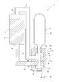
- FIG. 6 shows the concept of the sprinkler fire extinguishing apparatus of the fourth embodiment.
- the sprinkler fire extinguishing apparatus 51 includes a main tank 2, a sub tank 3, a sprinkler head 6 having a temperature sensor, the main tank 2 and the sprinkler head 6.
- the connecting pipe 9, the pipe 52, an opening member (cylinder pin) 53 that functions as a trigger, an urging member (coil spring) 54, and a fixing member 55 are configured.
- the structure of the main tank 2 and the sub tank 3 is the same as that of the sprinkler fire extinguisher 1 of the first embodiment.
- the main tank 2 is filled with the fire extinguishing agent A, and the sub tank 3 contains the compressed gas G. Filled.
- the main tank 2 is directly connected to the sprinkler head 6 through a metal pipe 9 as in the case of the sprinkler fire extinguishing device 31 of the second embodiment.
- the sub-tank 3 is filled with the compressed gas G as in the sprinkler fire extinguishing apparatus 1 of the first embodiment, but the tip of the discharge pipe 10 is a film body (for example, a metal film such as an aluminum foil or the like having a predetermined thickness). The film is covered (closed).
- the pipe 52 connecting the sub tank 3 and the main tank 2 is formed with a large diameter portion 52a. Inside the large diameter portion 52a, an opening member 53 and an urging member 54 functioning as a pin member are provided. Built in.
- the opening member 53 is made of metal, and the tip side is sharply pointed. Further, a support portion 53a is provided on the proximal end side of the opening member 53, and an insertion hole (not shown) is formed below the support portion 53a.
- a fixing member 55 is provided on the outer plate 24 of the sprinkler head 6 so as to protrude outward.
- the tip of the fixing member 55 is bent in an L shape, and a fixing pin 56 having a sharp tip is attached to the tip of a vertically rising portion.
- the fixing pin 56 is inserted into an insertion hole (not shown) of the support portion 53 a of the opening member 53, and the opening member 53 is fixed in a state where it is urged by the urging means 54.
- the fixing member 55 fixed to the outer plate 24 is also dropped together, so that the fixing pin 56 of the fixing member 55 is attached to the support portion 53a of the opening member 53. Remove from the insertion hole (not shown).
- the fixing pin 56 is thus detached from the opening member 53, the opening member 53 is pushed forward by the urging means 54, and the sharp tip breaks through the film body covering the opening of the sub tank 3, so that the sub tank 3 Is opened.
- the compressed gas G in the sub-tank 3 is ejected at a stroke and flows into the main tank via the pipe 8
- the extinguishing agent A in the main tank 2 is pressurized downward and from the tip of the sprinkler head 6 at a stroke. It blows out, hits the deflector 28, diffuses in all directions and falls. Such a series of operations can effectively suppress the fire.
- the sprinkler fire extinguishing device 51 is similar to the sprinkler fire extinguishing device 1 according to the first embodiment, the sprinkler fire extinguishing device 31 according to the second embodiment, and the sprinkler fire extinguishing device 41 according to the third embodiment. Since there is no need to provide a long pipe connecting the two, it can be constructed inexpensively and easily. In addition, since the pipe 9 and the pipe 52 are not easily rusted even when they are not used for a long period of time, maintenance is easy.
- the sprinkler fire extinguishing device 51 uses the compressed gas G in the sub tank 3 to apply the fire extinguishing agent A in the main tank 2 in the same manner as the sprinkler fire extinguishing device 1 in the first embodiment and the sprinkler fire extinguishing device 41 in the third embodiment. Since it can discharge
- the opening member 53 which is a pin member
- the biasing means 54 By pushing the opening member 53, which is a pin member, into the sub tank 3 by the biasing means 54, the compressed gas G in the sub tank 3 flows into the main tank 2, so that the trigger is surely activated in the event of a fire. It is possible to effectively prevent the fire from spreading.
- FIG. 8 shows the concept of the sprinkler fire extinguishing device according to the fifth embodiment.
- the sprinkler fire extinguishing device 61 includes a main tank 2, a sub tank 3, a housing 62 equipped with a temperature sensor and a trigger, the main tank 2 and the housing 62.
- the pipe 63, the deflector 28, and the like are connected.
- the structure of the main tank 2 is the same as that of the sprinkler fire extinguishing device 1 of the first embodiment, and the main tank 2 is filled with a fire extinguishing agent A.
- a discharge part 64 having a smaller diameter than the other part is formed at the tip (lower end) of the main tank 2, and the tip of the discharge part 64 is a film body (for example, an aluminum foil or the like) having a predetermined thickness. It is covered with a metal film or film) 65 (closed).
- a deflector 28 similar to the sprinkler fire extinguishing device 1 of the first embodiment is fixed to the lower side of the discharge portion 64 of the main tank 2.
- the sub tank 3 is filled with the compressed gas G as in the case of the sprinkler fire extinguishing apparatus 1 of the first embodiment.
- the tip of the discharge pipe 10 provided at the lower end is covered with a film body (for example, a metal film or film such as an aluminum foil) 66 having a predetermined thickness, like the tip of the discharge part 64 of the main tank 2. It is in a state (closed state).
- the housing 62 is composed of an upper cylindrical body 67 and a lower cylindrical body 68 that are formed in a flat cylindrical shape with a heat-resistant synthetic resin, and a lid body 69 that is formed in a disk shape with a similar heat-resistant synthetic resin.
- the heat-sensitive bodies 70 and 71 and the fusible body 72 functioning as temperature sensors, the opening member (cylinder pin) 73 and the biasing member (coil spring) 75 functioning as a trigger are integrated using the screw members 74 and 74. Is installed.
- a gas flow path 76 is provided on the side surface of the upper cylindrical body 67, and a screw groove (not shown) is threaded on the lower surface. Further, two screw insertion holes (not shown) are formed in the lower cylinder body 68 and the lid body 69 so as to face each other.
- the opening member 73 has a shape in which a metal pointed tube 77 having a sharpened tip is projected from the upper surface of a flat columnar base 78.
- a gas discharge path 79 is formed so as to connect the inside of the pointed tube body 77 and the side surface of the base 78.
- the two heat sensitive bodies 70 and 71 are formed in a donut plate shape with a central portion raised by metal, and are drilled so that two screw insertion holes (not shown) face each other.
- the fusible body 72 is formed in a donut plate shape by a resin that melts at a predetermined temperature, and is drilled so that two screw insertion holes (not shown) face each other, like the heat sensitive bodies 70 and 71.
- the central hole of the fusible body 72 is slightly larger than the outer diameter of the pointed tube 77 of the opening member 73, and the central hole of the heat sensitive bodies 70, 71 is the base 78 of the opening member 73. It is slightly larger than the outer diameter.
- the housing 62 has the opening 69 and the urging member 75 accommodated in the cavity of the lower cylinder 68, and the lid 69 is brought into contact with the lower surface of the lower cylinder 68, so that the upper surface of the lower cylinder 68 In a state where the central portions of the two heat sensitive bodies 70 and 71 and the fusible body 72 are placed, the screw members 74 and the screw insertion holes of the lid 69, the lower cylindrical body 68, the heat sensitive bodies 70 and 71, and the fusible body 72 are provided.
- the opening member 73 When the fusible body 26 is thus melted, the opening member 73 is pushed upward by the biasing means 75, and the sharp tip of the pointed tube body 77 breaks through the film body 66 covering the discharge pipe 10 of the sub tank 3.
- the sub tank 3 is in an open state. Further, when the opening member 73 is pushed up, the gas discharge passage 79 brings the inside of the sub tank 3 into communication with the gas passage 76. Further, as described above, when the sub tank 3 is opened, the compressed gas G in the sub tank 3 is ejected at once and flows into the main tank 2 via the gas flow path 76 and the pipe 63. Is pressed downward with high pressure.
- the sprinkler fire extinguishing device 61 is similar to the conventional sprinkler fire extinguishing device 1, the sprinkler fire extinguishing device 31 of the second embodiment, the sprinkler fire extinguishing device 41 of the third embodiment, and the sprinkler fire extinguishing device 51 of the fourth embodiment.
- the pipe 63 and the like are not easily rusted, so that maintenance is easy.
- the sprinkler fire extinguishing device 61 uses the compressed gas G in the sub tank 3 in the same manner as the sprinkler fire extinguishing device 1 of the first embodiment, the sprinkler fire extinguishing device 41 of the third embodiment, and the sprinkler fire extinguishing device 51 of the fourth embodiment. Since the fire extinguisher A in the main tank 2 can be released within a short time, it is possible to effectively prevent a fire from spreading. Furthermore, the sprinkler fire extinguishing device 61 has an opening member 73 with a trigger pointed at the tip and an urging member 75, and when the temperature sensor (the heat sensitive bodies 70 and 71 and the fusible body 72) detects a predetermined temperature.
- the compressed gas G in the sub-tank 3 is caused to flow into the main tank 2 by piercing the sub-tank 3 with the opening member 73 (pointed tube 77), which is a pin member, by the biasing means 75. Therefore, it is possible to effectively prevent the trigger from operating reliably and spreading fire.
- the configuration of the sprinkler fire extinguishing apparatus according to the present invention is not limited to the above-described embodiments, and the configurations of the main tank, the sub tank, the trigger, the temperature sensor, the sprinkler head, and the like depart from the spirit of the present invention. As long as it is not necessary, it can be changed as needed.
- the sprinkler head is not limited to the one that detects the temperature by melting the fusible body as in the above embodiments, but can be changed to one that uses a thermocouple.
- the second temperature sensor is not limited to the fuse, and may be changed to one using the thermal expansion of the element or one using a thermocouple. Is also possible.
- the opening member is not limited to the one that is urged by the urging member, and can be changed to one that opens the sub tank by a solenoid or the like. is there.
- the fire extinguishing agent to be filled in the main tank of the sprinkler fire extinguishing apparatus according to the present invention is not limited to a phosphate-based one in which polysaccharides, phosphates, and the like are blended with a surfactant, and carbon dioxide by chemical reaction. It is also possible to change to those that generate water or those of potassium salt type. Furthermore, it is also possible to use a fire extinguishing agent mainly composed of potassium carbonate, which is effective for igniting tempura oil.
- the fire extinguishing ability of the fire extinguishing device will be greatly improved.
- the compressed gas filled in the sub tank is not limited to CO 2 and can be changed to other compressed gases.
- the sprinkler fire extinguishing apparatus is not limited to the one that automatically injects the fire extinguishing agent only when the temperature sensor detects that the temperature is high, as in the above-described embodiment.
- a manual switch (81) for ejecting a fire extinguisher may be provided.
- means for applying a force to the members (the inner plate 23 and the outer plate 24 in the above embodiment) covering the opening of the sprinkler, or a temperature sensor for the sprinkler Means or the like for supplying power to a member (heating wire or the like) that heats can be used.
- the sprinkler fire extinguishing apparatus includes a pipe connecting the main tank and the sprinkler head, a pipe connecting the main tank and the sub tank, a pipe connecting the sub tank and the sprinkler head, the main tank and the housing, as in the above embodiment.
- a pipe connecting the main tank and the sprinkler head a pipe connecting the main tank and the sub tank, a pipe connecting the sub tank and the sprinkler head, the main tank and the housing, as in the above embodiment.
- pipes made of metal pipes for connecting the pipes
- pipes made of synthetic resin such as rubber or vinyl chloride
- it is more preferable to use a pressure-resistant type for example, one whose outer periphery is covered with a net-like body formed of synthetic fiber or wire).
- the sprinkler fire extinguishing apparatus when the sprinkler fire extinguishing apparatus according to the present invention is provided with a sub-tank, it is not limited to a mode in which the sub-tank is disposed outside the main tank as in the above-described embodiment, but is a commercially available fire extinguisher. In addition, it is possible to arrange a sub tank in the main tank.
- the sprinkler fire extinguishing apparatus according to the present invention exhibits excellent effects as described above, it can be suitably used as a simple fire extinguishing apparatus that is permanently installed in various buildings.
Abstract
【課題】シンプルな構造を有しており、安価かつ容易に構築することができる上、メンテナンスが容易で実用的なスプリンクラー消火装置を提供する。 【解決手段】スプリンクラー消火装置1は、消火剤を貯留したメインタンク2と、そのメインタンク2と接続されており温度センサ(所定の温度で溶融する可溶体)を有するスプリンクラーヘッド6とを備えている。そして、温度センサが所定の温度を検知すると(すなわち、可溶体が溶融すると)、メインタンク2内の消火剤Aをスプリンクラーヘッド6から外部へ放出させるようになっている。
Description
本発明は、ビルや住宅等の建造物の天井に備えられており、火災(天ぷら油への着火等の小規模な火災も含む)を検知すると自動的に周囲に放水を行うスプリンクラー消火装置に関するものである。
従来のスプリンクラー消火装置としては、特許文献1の如く、建造物の天井に設置されるスプリンクラーヘッドが、金属製の配管によって、地上あるいは地下に設けられた水槽あるいは水道設備と接続されているとともに、スプリンクラーヘッドの近傍に備えられる温度センサが、給水ポンプと電気的に接続されたものが知られている。そして、当該スプリンクラー消火装置は、温度センサが所定の数値以上の温度を感知すると、給水ポンプが水槽内の水を汲み上げて、スプリンクラーヘッドから排出させるようになっている。
しかしながら、上記特許文献1のスプリンクラー消火装置は、構造が複雑で大掛かりであるため、一般の住居に備えることは困難である。殊に、既設住宅については、専用の水道用配管を増設する必要があるため、設置するのが非常に困難である。また、水槽に常時、水を貯えておかなければならないし、長期間に亘って使用しないと、配管やポンプ等が錆付いて、肝心の火災の際に作動しない、という事態が起こり得る。加えて、誤って非火災時に作動をした場合には、大量の水が噴出されるため、店舗等において多くの商品が水浸しとなって甚大な損害が生ずる事態も起こり得る。
本発明の目的は、上記従来のスプリンクラー消火装置が有する問題点を解消し、シンプルでコンパクトな構造を有しており、安価かつ容易に構築することができ、一般住宅、既設住宅にも容易に設置することができる上、メンテナンスが容易で実用的なスプリンクラー消火装置を提供することにある。加えて、少量の消火剤で高い消火能力を発揮するため、誤って非火災時に作動をした場合でも、消火剤の噴出に起因した甚大な損害が生ずることのないスプリンクラー消火装置を提供することにある。
本発明の内、請求項1に記載された発明は、消火剤を貯留したメインタンクと温度を検知するためのセンサとを備えており、前記センサが所定の温度を検知すると、メインタンク内の消火剤を外部へ放出させることを特徴とするスプリンクラー消火装置である。
請求項2に記載された発明は、請求項1に記載された発明において、前記センサがスプリンクラーヘッドに設けられているとともに、そのスプリンクラーヘッドに前記メインタンクが接続されており、前記センサが所定の温度を検知すると、前記メインタンク内の消火剤を前記スプリンクラーヘッドから外部へ放出させることを特徴とするものである。
請求項3に記載された発明は、請求項1、または請求項2に記載された発明において、圧縮ガスを充填したサブタンクと、そのサブタンクを開口させるためのトリガーとを備えており、前記センサが所定の温度を検知すると、前記トリガーが連動して前記サブタンクを開口し、サブタンク内の圧縮ガスを前記メインタンク内へ流入させることによって、メインタンク内の消火剤を放出させることを特徴とするものである。
請求項4に記載された発明は、請求項1~3のいずれかに記載された発明において、前記トリガーが、付勢手段とピン部材とを有しており、前記センサが所定の温度を検知すると、付勢手段によってピン部材を前記サブタンクに突き刺すことによって、サブタンク内の圧縮ガスを前記メインタンク内へ流入させることを特徴とするものである。
請求項1に記載のスプリンクラー消火装置は、従来のスプリンクラー消火装置のように水槽等とスプリンクラーヘッドとを結ぶ長い配管を設ける必要がないので、安価かつ容易に構築することができる。その上、長期間に亘って使用されない場合でも、配管等が錆びるという事態が生じないので、メンテナンスが容易である。また、どのようなタイプの火災であっても効率的に鎮火することができる。
請求項2に記載のスプリンクラー消火装置は、スプリンクラーヘッドに設けられたセンサが所定の温度を検知すると、メインタンク内の消火剤をスプリンクラーヘッドから外部へ放出させるため、火事を敏感に検知することができる上、非常に効率的に鎮火することができる。
請求項3に記載のスプリンクラー消火装置は、サブタンク内の圧縮ガスを利用して、メインタンク内の消火剤をスプリンクラーヘッドから短時間の内に放出させることができるので、火災が拡がる事態を効果的に防止することができる。
請求項4に記載のスプリンクラー消火装置は、火災の際にトリガーが確実に作動して、延焼する事態を効果的に防止することができる。
以下、本発明に係るスプリンクラー消火装置の一実施形態について、図面に基づいて詳細に説明する。
[実施例1]
<実施例1のスプリンクラー消火装置の構造>
図1は、スプリンクラー消火装置の概念を示したものであり、スプリンクラー消火装置1は、メインタンク2、サブタンク3、トリガーとして機能する栓部材11、栓部材11を収納したハウジング7、温度センサを有するスプリンクラーヘッド6、ハウジング7とメインタンク2とを接続した配管8、メインタンクとハウジング7とを接続した配管9等によって構成されている。
<実施例1のスプリンクラー消火装置の構造>
図1は、スプリンクラー消火装置の概念を示したものであり、スプリンクラー消火装置1は、メインタンク2、サブタンク3、トリガーとして機能する栓部材11、栓部材11を収納したハウジング7、温度センサを有するスプリンクラーヘッド6、ハウジング7とメインタンク2とを接続した配管8、メインタンクとハウジング7とを接続した配管9等によって構成されている。
メインタンク2は、金属(たとえば、アルミニウム)によって中空の円柱状に形成されており、約3.0リットルの容積を有している。また、メインタンク2の上端には、流入口13が設けられており、その流入口13には、金属製の配管8の先端が接続されている。一方、下端には、排出口14が設けられており、その排出口14には、金属製の配管9の基端が接続されている。そして、当該メインタンク2の内部には、約2.0リットルの消火剤A(たとえば、界面活性剤に多糖類やリン酸塩等を配合したリン酸塩系の消火剤)が充填されている。
一方、サブタンク3は、金属(たとえば、アルミニウム)によって中空の円柱状に形成されており、約500ml(ミリリットル)の容積を有している。また、サブタンク3の下端際には、円柱状の排出管10が他の部分より小径になるように形成されており、当該排出管10の先端(下端)には、排出口12が設けられている。そして、その排出管10の先端は、ハウジング7に接続されている。そして、当該サブタンク3の内部には、圧縮ガスG(CO2)が充填されている。
一方、ハウジング7は、耐熱性の合成樹脂によって略円柱状の外形となるように形成されている。そして、仕切板15によって、内部の空間が、第一室7aと第二室7bとの2つに仕切られた状態になっている。当該仕切板15の略中央には、挿通孔16が形成されており、その挿通孔16に、後述する栓部材11の軸心が挿通した状態になっている。さらに、第一室7aには、ガス流入孔17とガス排出孔18とが設けられており、それぞれ、サブタンク3の排出管10、配管8の基端と接続された状態になっている。また、第二室7bには、消火剤流入孔19と消火剤排出孔20とが設けられており、消火剤流入孔19は、配管9の先端と接続された状態になっている。
また、栓部材11は、金属によって略棒状に形成されており、円柱状の軸体11aの下端に、ハウジング7の消火剤排出孔20を閉じるための厚肉のフランジ状の栓体11bが設けられている。当該栓体11bは、スプリンクラーヘッド6の外プレート24(後述する)と係合した状態になっている。また、軸体11aの上端には、ハウジング7のガス流入孔17の下端(サブタンク3の排出管10の先端)を閉じるためのフランジ体11cが設けられており、そのフランジ体11cの上側には、突起部11dが形成されている。当該突起部11dは、先端が尖った状態になっており、片側(ガス排出口18の設置側)に、傾斜面が形成されている。そして、当該栓部材11は、フランジ体11cをサブタンク3の排出管10の下端に押し付けて、その排出管10の排出口12を突起部11dで塞ぐとともに、栓体11bでハウジング7の消火剤排出孔20を塞いだ状態となるようにハウジング7に設置されている。
また、図2は、スプリンクラーヘッド6を示したものであり、スプリンクラーヘッド6は、本体21、フレーム22、内プレート23、外プレート24、感熱体25,25・・、可溶体26、リング体27、デフレクタ28等を組み付けることによって構成されている。なお、可溶体26は、温度センサとして機能するものであり、ハンダ(鉛とスズを主成分とした合金)によって形成されており、所定の温度(約96℃)で溶融するようになっている。
当該スプリンクラーヘッド6は、外プレート24の周辺が高温になると、可溶体26が溶融することによって外プレート24が内プレート23に対して落下する。そのように外プレート24が落下すると、内プレート23の上端のフランジ体と外プレート24の上端のフランジ体との間隔が拡がり、2つのフランジ体の外周縁に形成された溝内に内向きに付勢された状態で嵌まり込んでいたリング体27が、外径を小さくするように軸心方向に入り込むため、当該リング体27とフレーム22との係合状態が解除される。そして、そのようにリング体27とフレーム22との係合状態が解除されると、図2(b)の如く、内プレート23と外プレート24とが一緒に落下する。さらに、そのように内プレート23と外プレート24とが一緒に落下すると、内プレート23によって上方へ付勢されていたデフレクタ28が、図2(c)の如く、フレーム22の内部から降下する。
<実施例1のスプリンクラー消火装置の作動内容>
上記の如く構成されたスプリンクラー消火装置1は、ハウジング7を天井板の上側に載置させ、スプリンクラーヘッド6を天井板から露出させた状態で、建造物内に設置して使用する。そのように設置されたスプリンクラー消火装置1においては、建造物内で火災が発生し、スプリンクラーヘッド6の周辺が高温になると、上述したように、温度センサである可溶体26が所定の温度で溶融することを契機として、図3の如く、内プレート23と外プレート24とが一緒に落下する。そして、スプリンクラーヘッド6の内プレート23と外プレート24とが一緒に落下すると、外プレート24と係合している栓部材11が下側に引っ張られるため、栓体11bが落下して、ハウジング7の消火剤排出孔20から消火剤Aが流れ落ちる。
上記の如く構成されたスプリンクラー消火装置1は、ハウジング7を天井板の上側に載置させ、スプリンクラーヘッド6を天井板から露出させた状態で、建造物内に設置して使用する。そのように設置されたスプリンクラー消火装置1においては、建造物内で火災が発生し、スプリンクラーヘッド6の周辺が高温になると、上述したように、温度センサである可溶体26が所定の温度で溶融することを契機として、図3の如く、内プレート23と外プレート24とが一緒に落下する。そして、スプリンクラーヘッド6の内プレート23と外プレート24とが一緒に落下すると、外プレート24と係合している栓部材11が下側に引っ張られるため、栓体11bが落下して、ハウジング7の消火剤排出孔20から消火剤Aが流れ落ちる。
また、上記の如く、スプリンクラーヘッド6の内プレート23と外プレート24とが一緒に落下すると、栓部材11が下側に引っ張られることにより、栓部材の突起部11dが、サブタンク3の排出管10の排出口12から抜け落ちるため、排出口12が開口した状態となる。そして、そのように排出口12が開口すると、サブタンク3の圧縮ガスG(CO2ガス)が一気に噴出して、配管8を介してメインタンク内に流れ込む。そのため、メインタンク2内の消火剤Aが、下方に加圧されて、その圧力がハウジングの第二室7bに伝播するため、ハウジング7の消火剤排出孔20から消火剤Aが一気に(勢いよく)噴出する。
一方、スプリンクラーヘッド6の内プレート23と外プレート24とが一緒に落下すると、上述したように、デフレクタ28(図示せず)が、フレーム22の内部から降下するため、ハウジング7の消火剤排出孔20から噴き出した消火剤Aが、当該デフレクタ28に当たって、四方八方に拡散して落下する。かかる一連の動作によって、効果的に鎮火することが可能となる。
<実施例1のスプリンクラー消火装置の効果>
スプリンクラー消火装置1は、上記の如く、消火剤Aを貯留したメインタンク2と、そのメインタンク2と接続されており温度センサ(スプリンクラーヘッド6の可溶体26)を有するスプリンクラーヘッド6とを備えており、温度センサが所定の温度を検知すると(すなわち、可溶体26が溶融すると)、メインタンク2内の消火剤Aをスプリンクラーヘッド6から外部へ放出させるものである。したがって、スプリンクラー消火装置1は、従来のスプリンクラー消火装置のように水槽等とスプリンクラーヘッドとを結ぶ長い配管を設ける必要がないので、安価かつ容易に構築することができる。その上、長期間に亘って使用されない場合でも、配管8や配管9等が錆びにくいので、メンテナンスが容易である。また、スプリンクラー消火装置1は、圧縮ガスGを充填したサブタンク3と、そのサブタンク3を開口させるためのトリガー(栓部材11)とを備えており、温度センサが所定の温度を検知すると、トリガーが連動してサブタンク3を開口し、サブタンク3内の圧縮ガスGをメインタンク2内へ流入させることによって、メインタンク2内の消火剤Aをスプリンクラーヘッド6へ流下させるものであるため、サブタンク3内の圧縮ガスGを利用して、メインタンク2内の消火剤Aをスプリンクラーヘッド6から短時間の内に放出させることができるので、火災が拡がる事態を効果的に防止することができる。
スプリンクラー消火装置1は、上記の如く、消火剤Aを貯留したメインタンク2と、そのメインタンク2と接続されており温度センサ(スプリンクラーヘッド6の可溶体26)を有するスプリンクラーヘッド6とを備えており、温度センサが所定の温度を検知すると(すなわち、可溶体26が溶融すると)、メインタンク2内の消火剤Aをスプリンクラーヘッド6から外部へ放出させるものである。したがって、スプリンクラー消火装置1は、従来のスプリンクラー消火装置のように水槽等とスプリンクラーヘッドとを結ぶ長い配管を設ける必要がないので、安価かつ容易に構築することができる。その上、長期間に亘って使用されない場合でも、配管8や配管9等が錆びにくいので、メンテナンスが容易である。また、スプリンクラー消火装置1は、圧縮ガスGを充填したサブタンク3と、そのサブタンク3を開口させるためのトリガー(栓部材11)とを備えており、温度センサが所定の温度を検知すると、トリガーが連動してサブタンク3を開口し、サブタンク3内の圧縮ガスGをメインタンク2内へ流入させることによって、メインタンク2内の消火剤Aをスプリンクラーヘッド6へ流下させるものであるため、サブタンク3内の圧縮ガスGを利用して、メインタンク2内の消火剤Aをスプリンクラーヘッド6から短時間の内に放出させることができるので、火災が拡がる事態を効果的に防止することができる。
[実施例2]
<実施例2のスプリンクラー消火装置の構造>
図4は、実施例2のスプリンクラー消火装置の概念を示したものであり、スプリンクラー消火装置31は、メインタンク2、温度センサを有するスプリンクラーヘッド6、配管9等によって構成されている。そして、メインタンク2内には、実施例1のスプリンクラー消火装置1と同様に、消火剤Aが充填されているとともに、圧縮ガスGも充填されており、消火剤Aが下方に加圧された状態になっている。また、メインタンク2が金属製の配管9によって、直接的にスプリンクラーヘッド6と接続された状態になっている。
<実施例2のスプリンクラー消火装置の構造>
図4は、実施例2のスプリンクラー消火装置の概念を示したものであり、スプリンクラー消火装置31は、メインタンク2、温度センサを有するスプリンクラーヘッド6、配管9等によって構成されている。そして、メインタンク2内には、実施例1のスプリンクラー消火装置1と同様に、消火剤Aが充填されているとともに、圧縮ガスGも充填されており、消火剤Aが下方に加圧された状態になっている。また、メインタンク2が金属製の配管9によって、直接的にスプリンクラーヘッド6と接続された状態になっている。
<実施例2のスプリンクラー消火装置の作動内容>
上記の如く構成されたスプリンクラー消火装置31においては、建造物内で火災が発生し、スプリンクラーヘッド6の周辺が高温になると、実施例1のスプリンクラー消火装置1と同様に、スプリンクラーヘッド6の温度センサである可溶体26が所定の温度で溶け出すことによって、内プレート23と外プレート24とが一緒に落下する。そして、内プレート23と外プレート24とが一緒に落下すると、スプリンクラーヘッド6の先端が開口した状態となるため、メインタンク2内で加圧されていた消火剤Aが、一気に噴出し、デフレクタ28に当たって、四方八方に拡散して落下する。かかる一連の動作によって、効果的に鎮火することが可能となる。
上記の如く構成されたスプリンクラー消火装置31においては、建造物内で火災が発生し、スプリンクラーヘッド6の周辺が高温になると、実施例1のスプリンクラー消火装置1と同様に、スプリンクラーヘッド6の温度センサである可溶体26が所定の温度で溶け出すことによって、内プレート23と外プレート24とが一緒に落下する。そして、内プレート23と外プレート24とが一緒に落下すると、スプリンクラーヘッド6の先端が開口した状態となるため、メインタンク2内で加圧されていた消火剤Aが、一気に噴出し、デフレクタ28に当たって、四方八方に拡散して落下する。かかる一連の動作によって、効果的に鎮火することが可能となる。
<実施例2のスプリンクラー消火装置の効果>
実施例2のスプリンクラー消火装置31は、実施例1のスプリンクラー消火装置1と同様に、従来のスプリンクラー消火装置のように水槽等とスプリンクラーヘッドとを結ぶ長い配管を設ける必要がないので、安価かつ容易に構築することができる。その上、長期間に亘って使用されない場合でも、配管9等が錆びにくいので、メンテナンスが容易である。また、メインタンク2内の圧縮ガスGを利用して、消火剤Aをスプリンクラーヘッド6から短時間の内に放出させることができるので、火災が拡がる事態を効果的に防止することができる。
実施例2のスプリンクラー消火装置31は、実施例1のスプリンクラー消火装置1と同様に、従来のスプリンクラー消火装置のように水槽等とスプリンクラーヘッドとを結ぶ長い配管を設ける必要がないので、安価かつ容易に構築することができる。その上、長期間に亘って使用されない場合でも、配管9等が錆びにくいので、メンテナンスが容易である。また、メインタンク2内の圧縮ガスGを利用して、消火剤Aをスプリンクラーヘッド6から短時間の内に放出させることができるので、火災が拡がる事態を効果的に防止することができる。
[実施例3]
<実施例3のスプリンクラー消火装置の構造>
図5は、実施例3のスプリンクラー消火装置の概念を示したものであり、スプリンクラー消火装置41は、メインタンク2、サブタンク3、トリガーとして機能するバルブ(電磁弁)42、温度センサを有するスプリンクラーヘッド6、配管9、第二温度センサ(ヒューズ)43、信号線44、配管45等によって構成されている。
<実施例3のスプリンクラー消火装置の構造>
図5は、実施例3のスプリンクラー消火装置の概念を示したものであり、スプリンクラー消火装置41は、メインタンク2、サブタンク3、トリガーとして機能するバルブ(電磁弁)42、温度センサを有するスプリンクラーヘッド6、配管9、第二温度センサ(ヒューズ)43、信号線44、配管45等によって構成されている。
メインタンク2、サブタンク3およびスプリンクラーヘッド6の構造は、実施例1のスプリンクラー消火装置1と同様であり、メインタンク2内には、消火剤Aが充填されており、サブタンク3内には、圧縮ガスGが充填されている。また、メインタンク2は、実施例2のスプリンクラー消火装置31と同様に、金属製の配管9によって、直接的にスプリンクラーヘッド6と接続されている。一方、サブタンク3とメインタンク2とを接続する配管45には、バルブ(電磁弁)42が設けられており、当該バルブ42は、信号線44によって、第二温度センサ43に接続された状態になっている。
<実施例3のスプリンクラー消火装置の作動内容>
上記の如く構成された実施例3のスプリンクラー消火装置41は、スプリンクラーヘッド6を天井板Wから露出させた状態でハウジング7を天井板Wの上側に載置し、第二温度センサ43をスプリンクラーヘッド6の近傍に配置させた状態で、建造物内に設置して使用する。当該スプリンクラー消火装置41においては、建造物内で火災が発生し、スプリンクラーヘッド6の周辺が高温になると、実施例1のスプリンクラー消火装置1と同様に、スプリンクラーヘッド6の温度センサである可溶体26が所定の温度で溶け出すことによって、内プレート23と外プレート24とが一緒に落下し、スプリンクラーヘッド6の先端が開口した状態となる。
上記の如く構成された実施例3のスプリンクラー消火装置41は、スプリンクラーヘッド6を天井板Wから露出させた状態でハウジング7を天井板Wの上側に載置し、第二温度センサ43をスプリンクラーヘッド6の近傍に配置させた状態で、建造物内に設置して使用する。当該スプリンクラー消火装置41においては、建造物内で火災が発生し、スプリンクラーヘッド6の周辺が高温になると、実施例1のスプリンクラー消火装置1と同様に、スプリンクラーヘッド6の温度センサである可溶体26が所定の温度で溶け出すことによって、内プレート23と外プレート24とが一緒に落下し、スプリンクラーヘッド6の先端が開口した状態となる。
また、スプリンクラーヘッド6の周辺が高温になると、第二温度センサ43であるヒューズが切れて、当該ヒューズの切断に起因した検知信号が信号線44を介して、バルブ42に伝えられ、バルブ42が開動作を実行する。そして、そのようにバルブ42が開くと、サブタンク3の圧縮ガスGが一気に噴出して、配管45を介してメインタンク2内に流れ込む。そのため、メインタンク2内の消火剤Aが、下方に加圧されて、スプリンクラーヘッド6の先端から一気に噴出し、デフレクタ28に当たって、四方八方に拡散して落下する。かかる一連の動作によって、効果的に鎮火することが可能となる。
<実施例3のスプリンクラー消火装置の効果>
実施例3のスプリンクラー消火装置41は、実施例1のスプリンクラー消火装置1や実施例2のスプリンクラー消火装置31と同様に、従来のスプリンクラー消火装置のように水槽等とスプリンクラーヘッドとを結ぶ長い配管を設ける必要がないので、安価かつ容易に構築することができる。その上、長期間に亘って使用されない場合でも、配管9や配管45等が錆びにくいので、メンテナンスが容易である。また、スプリンクラー消火装置41は、実施例1のスプリンクラー消火装置1と同様に、サブタンク3内の圧縮ガスGを利用して、メインタンク2内の消火剤Aをスプリンクラーヘッド6から短時間の内に放出させることができるので、火災が拡がる事態を効果的に防止することができる。さらに、スプリンクラー消火装置41は、サブタンク3を開口させるトリガーが、第二温度センサ43と電気的に接続されたバルブ42であるため、火災の際にトリガーが確実に作動して、延焼する事態を効果的に防止することができる。
実施例3のスプリンクラー消火装置41は、実施例1のスプリンクラー消火装置1や実施例2のスプリンクラー消火装置31と同様に、従来のスプリンクラー消火装置のように水槽等とスプリンクラーヘッドとを結ぶ長い配管を設ける必要がないので、安価かつ容易に構築することができる。その上、長期間に亘って使用されない場合でも、配管9や配管45等が錆びにくいので、メンテナンスが容易である。また、スプリンクラー消火装置41は、実施例1のスプリンクラー消火装置1と同様に、サブタンク3内の圧縮ガスGを利用して、メインタンク2内の消火剤Aをスプリンクラーヘッド6から短時間の内に放出させることができるので、火災が拡がる事態を効果的に防止することができる。さらに、スプリンクラー消火装置41は、サブタンク3を開口させるトリガーが、第二温度センサ43と電気的に接続されたバルブ42であるため、火災の際にトリガーが確実に作動して、延焼する事態を効果的に防止することができる。
[実施例4]
<実施例4のスプリンクラー消火装置の構造>
図6は、実施例4のスプリンクラー消火装置の概念を示したものであり、スプリンクラー消火装置51は、メインタンク2、サブタンク3、温度センサを有するスプリンクラーヘッド6、メインタンク2とスプリンクラーヘッド6とを接続した配管9、配管52、トリガーとして機能する開口部材(ボンベピン)53、付勢部材(コイルバネ)54および固定部材55等によって構成されている。
<実施例4のスプリンクラー消火装置の構造>
図6は、実施例4のスプリンクラー消火装置の概念を示したものであり、スプリンクラー消火装置51は、メインタンク2、サブタンク3、温度センサを有するスプリンクラーヘッド6、メインタンク2とスプリンクラーヘッド6とを接続した配管9、配管52、トリガーとして機能する開口部材(ボンベピン)53、付勢部材(コイルバネ)54および固定部材55等によって構成されている。
メインタンク2、サブタンク3のの構造は、実施例1のスプリンクラー消火装置1と同様であり、メインタンク2内には、消火剤Aが充填されており、サブタンク3内には、圧縮ガスGが充填されている。また、メインタンク2は、実施例2のスプリンクラー消火装置31と同様に、金属製の配管9によって、直接的にスプリンクラーヘッド6と接続されている。
また、サブタンク3は、実施例1のスプリンクラー消火装置1と同様に、圧縮ガスGが充填されているが、排出管10の先端が所定の厚みの膜体(たとえば、アルミ箔等の金属膜やフィルム)によって覆われた状態になっている(閉じられた状態になっている)。さらに、サブタンク3とメインタンク2とを接続する配管52には、大径部52aが形成されており、その大径部52aの内部に、ピン部材として機能する開口部材53および付勢部材54が内蔵されている。開口部材53は、金属によって形成されており、先端側が鋭利に尖った状態になっている。また、開口部材53の基端側には、支持部53aが設けられており、当該支持部53aの下側には、挿入孔(図示せず)が穿設されている。
一方、スプリンクラーヘッド6の外プレート24には、固定部材55が外側へ突出するように設けられている。当該固定部材55の先端は、L字状に折り曲がっており、垂直に立ち上がった部分の先端に、先端を尖らせた固定ピン56が取り付けられている。そして、その固定ピン56が、開口部材53の支持部53aの挿入孔(図示せず)に挿入され、開口部材53を付勢手段54によって付勢された状態で固定している。
<実施例4のスプリンクラー消火装置の作動内容>
上記の如く構成された実施例4のスプリンクラー消火装置51においては、建造物内で火災が発生し、スプリンクラーヘッド6の周辺が高温になると、実施例1のスプリンクラー消火装置1と同様に、スプリンクラーヘッド6の温度センサである可溶体26が所定の温度で溶融することによって、図7の如く、内プレート23と外プレート24とが一緒に落下し、スプリンクラーヘッド6の先端が開口した状態となる。
上記の如く構成された実施例4のスプリンクラー消火装置51においては、建造物内で火災が発生し、スプリンクラーヘッド6の周辺が高温になると、実施例1のスプリンクラー消火装置1と同様に、スプリンクラーヘッド6の温度センサである可溶体26が所定の温度で溶融することによって、図7の如く、内プレート23と外プレート24とが一緒に落下し、スプリンクラーヘッド6の先端が開口した状態となる。
また、内プレート23と外プレート24とが一緒に落下すると、外プレート24に固定された固定部材55も一緒に落下するため、固定部材55の固定ピン56が、開口部材53の支持部53aの挿入孔(図示せず)から離脱する。そして、そのように固定ピン56が開口部材53から離脱すると、開口部材53が付勢手段54によって前方へ押し出され、鋭利な先端がサブタンク3の開口部を覆った膜体を突き破るため、サブタンク3が開口した状態となる。そして、サブタンク3の圧縮ガスGが一気に噴出して、配管8を介してメインタンク内に流れ込むため、メインタンク2内の消火剤Aが、下方に加圧されて、スプリンクラーヘッド6の先端から一気に噴出し、デフレクタ28に当たって、四方八方に拡散して落下する。かかる一連の動作によって、効果的に鎮火することが可能となる。
<実施例4のスプリンクラー消火装置の効果>
スプリンクラー消火装置51は、実施例1のスプリンクラー消火装置1、実施例2のスプリンクラー消火装置31や実施例3のスプリンクラー消火装置41と同様に、従来のスプリンクラー消火装置のように水槽等とスプリンクラーヘッドとを結ぶ長い配管を設ける必要がないので、安価かつ容易に構築することができる。その上、長期間に亘って使用されない場合でも、配管9や配管52等が錆びにくいので、メンテナンスが容易である。また、スプリンクラー消火装置51は、実施例1のスプリンクラー消火装置1や実施例3のスプリンクラー消火装置41と同様に、サブタンク3内の圧縮ガスGを利用して、メインタンク2内の消火剤Aをスプリンクラーヘッド6から短時間の内に放出させることができるので、火災が拡がる事態を効果的に防止することができる。さらに、スプリンクラー消火装置51は、トリガーが先端を尖らせた開口部材53と付勢部材54とを有しており、温度センサ(スプリンクラーヘッド6の可溶体26)が所定の温度を検知すると、付勢手段54によってピン部材である開口部材53をサブタンク3に突き刺すことによって、サブタンク3内の圧縮ガスGをメインタンク2内へ流入させるものであるため、火災の際にトリガーが確実に作動して、延焼する事態を効果的に防止することができる。
スプリンクラー消火装置51は、実施例1のスプリンクラー消火装置1、実施例2のスプリンクラー消火装置31や実施例3のスプリンクラー消火装置41と同様に、従来のスプリンクラー消火装置のように水槽等とスプリンクラーヘッドとを結ぶ長い配管を設ける必要がないので、安価かつ容易に構築することができる。その上、長期間に亘って使用されない場合でも、配管9や配管52等が錆びにくいので、メンテナンスが容易である。また、スプリンクラー消火装置51は、実施例1のスプリンクラー消火装置1や実施例3のスプリンクラー消火装置41と同様に、サブタンク3内の圧縮ガスGを利用して、メインタンク2内の消火剤Aをスプリンクラーヘッド6から短時間の内に放出させることができるので、火災が拡がる事態を効果的に防止することができる。さらに、スプリンクラー消火装置51は、トリガーが先端を尖らせた開口部材53と付勢部材54とを有しており、温度センサ(スプリンクラーヘッド6の可溶体26)が所定の温度を検知すると、付勢手段54によってピン部材である開口部材53をサブタンク3に突き刺すことによって、サブタンク3内の圧縮ガスGをメインタンク2内へ流入させるものであるため、火災の際にトリガーが確実に作動して、延焼する事態を効果的に防止することができる。
[実施例5]
<実施例5のスプリンクラー消火装置の構造>
図8は、実施例5のスプリンクラー消火装置の概念を示したものであり、スプリンクラー消火装置61は、メインタンク2、サブタンク3、温度センサおよびトリガーを装着したハウジング62、メインタンク2とハウジング62とを接続した配管63、デフレクター28等によって構成されている。
<実施例5のスプリンクラー消火装置の構造>
図8は、実施例5のスプリンクラー消火装置の概念を示したものであり、スプリンクラー消火装置61は、メインタンク2、サブタンク3、温度センサおよびトリガーを装着したハウジング62、メインタンク2とハウジング62とを接続した配管63、デフレクター28等によって構成されている。
メインタンク2の構造は、実施例1のスプリンクラー消火装置1と同様であり、メインタンク2内には、消火剤Aが充填されている。そして、メインタンク2の先端(下端)には、他の部分よりも小径の排出部64が形成されており、その排出部64の先端は、所定の厚みの膜体(たとえば、アルミ箔等の金属膜やフィルム)65によって覆われた状態になっている(閉じられた状態になっている)。さらに、メインタンク2の排出部64の下側には、実施例1のスプリンクラー消火装置1と同様なデフレクタ28が固着されている。
一方、サブタンク3には、実施例1のスプリンクラー消火装置1と同様に、圧縮ガスGが充填されている。そして、下端に設けられた排出管10の先端は、メインタンク2の排出部64の先端と同様に、所定の厚みの膜体(たとえば、アルミ箔等の金属膜やフィルム)66によって覆われた状態になっている(閉じられた状態になっている)。
また、ハウジング62は、耐熱性の合成樹脂によって扁平な円柱状に形成された上筒体67および下筒体68と、同様な耐熱性の合成樹脂によって円盤状に形成された蓋体69とによって構成されており、ネジ部材74,74を利用して、温度センサとして機能する感熱体70,71および可溶体72、トリガーとして機能する開口部材(ボンベピン)73および付勢部材(コイルバネ)75が一体的に装着されている。上筒体67の側面には、ガス流路76が設けられており、下面にはネジ溝(図示せず)が螺刻されている。また、下筒体68および蓋体69には、2つのネジ挿通孔(図示せず)が、対向するように穿設されている。
さらに、開口部材73は、先端を鋭利に尖らせた金属製の尖筒体77を、扁平な円柱状の基台78の上面から突出させた形状を有している。そして、尖筒体77の内部と基台78の側面とを繋ぐようにガス排出路79が形成されている。
一方、2つの感熱体70,71は、金属によって中央部分を隆起させたドーナッツ板状に形成されており、2つのネジ挿通孔(図示せず)が対向するように穿設されている。さらに、可溶体72は、所定の温度で溶融する樹脂によってドーナッツ板状に形成されており、感熱体70,71と同様に、2つのネジ挿通孔(図示せず)が対向するように穿設されている。なお、可溶体72の中央の孔は、開口部材73の尖筒体77の外径よりも若干大径になっており、感熱体70,71の中央の孔は、開口部材73の基台78の外径よりも若干大径になっている。
ハウジング62は、下筒体68の空洞部内に、開口部材73および付勢部材75を収納した状態で、当該下筒体68の下面に蓋体69を当接させ、下筒体68の上面に2枚の感熱体70,71および可溶体72の中央部分を載置した状態で、蓋体69、下筒体68、感熱体70,71および可溶体72の各ネジ挿通孔にネジ部材74,74を挿通させ、それらのネジ部材74,74の先端部分を、上筒体67のネジ孔に螺着させることによって、温度センサである感熱体70,71および可溶体72、トリガーである開口部材73および付勢部材75を装着した状態で、一体的に組み付けられている。そして、付勢部材75によって上向きに付勢された開口部材73の基台78が、可溶体72の中央部分によって押圧されて下筒体68の空洞部内に収納された状態になっている。そして、そのように組み付けられたハウジング62の上筒体67の空洞部内に、サブタンク3の下端(排出管10)が挿入されて固着されている。
<実施例5のスプリンクラー消火装置の作動内容>
上記の如く構成された実施例5のスプリンクラー消火装置61は、メインタンク2の排出部64およびハウジング62の温度センサ(感熱体70,71および可溶体72)を天井Wから下側に露出させた状態で、天井裏に装着される。そのように設置されたスプリンクラー消火装置61においては、建造物内で火災が発生し、感熱体70,71の周辺が高温になると、図9の如く、それら感熱体70,71と接触した可溶体72が所定の温度で溶融する。
上記の如く構成された実施例5のスプリンクラー消火装置61は、メインタンク2の排出部64およびハウジング62の温度センサ(感熱体70,71および可溶体72)を天井Wから下側に露出させた状態で、天井裏に装着される。そのように設置されたスプリンクラー消火装置61においては、建造物内で火災が発生し、感熱体70,71の周辺が高温になると、図9の如く、それら感熱体70,71と接触した可溶体72が所定の温度で溶融する。
そして、そのように可溶体26が溶融すると、開口部材73が付勢手段75によって上方へ押し上げられ、尖筒体77の鋭利な先端がサブタンク3の排出管10を覆った膜体66を突き破るため、サブタンク3が開口した状態となる。また、開口部材73が押し上げられると、ガス排出路79によって、サブタンク3の内部とガス流路76とが連通した状態になる。さらに、上記の如く、サブタンク3が開口すると、サブタンク3の圧縮ガスGが一気に噴出して、ガス流路76および配管63を介してメインタンク2内に流れ込むため、メインタンク2内の消火剤Aが、高い圧力で下方に加圧される。そのようにメインタンク2内の消火剤Aが下方に加圧されると、メインタンク2の排出部64に装着されている膜体65が破れて、消火剤Aが排出部64から一気に噴出し、デフレクタ28に当たって、四方八方に拡散して落下する。かかる一連の動作によって、効果的に鎮火することが可能となる。
<実施例5のスプリンクラー消火装置の効果>
スプリンクラー消火装置61は、実施例1のスプリンクラー消火装置1、実施例2のスプリンクラー消火装置31、実施例3のスプリンクラー消火装置41や実施例4のスプリンクラー消火装置51と同様に、従来のスプリンクラー消火装置のように水槽等とスプリンクラーヘッドとを結ぶ長い配管を設ける必要がないので、安価かつ容易に構築することができる。その上、長期間に亘って使用されない場合でも、配管63等が錆びにくいので、メンテナンスが容易である。また、スプリンクラー消火装置61は、実施例1のスプリンクラー消火装置1、実施例3のスプリンクラー消火装置41や実施例4のスプリンクラー消火装置51と同様に、サブタンク3内の圧縮ガスGを利用して、メインタンク2内の消火剤Aを短時間の内に放出させることができるので、火災が拡がる事態を効果的に防止することができる。さらに、スプリンクラー消火装置61は、トリガーが先端を尖らせた開口部材73と付勢部材75とを有しており、温度センサ(感熱体70,71および可溶体72)が所定の温度を検知すると、付勢手段75によってピン部材である開口部材73(尖筒体77)をサブタンク3に突き刺すことによって、サブタンク3内の圧縮ガスGをメインタンク2内へ流入させるものであるため、火災の際にトリガーが確実に作動して、延焼する事態を効果的に防止することができる。
スプリンクラー消火装置61は、実施例1のスプリンクラー消火装置1、実施例2のスプリンクラー消火装置31、実施例3のスプリンクラー消火装置41や実施例4のスプリンクラー消火装置51と同様に、従来のスプリンクラー消火装置のように水槽等とスプリンクラーヘッドとを結ぶ長い配管を設ける必要がないので、安価かつ容易に構築することができる。その上、長期間に亘って使用されない場合でも、配管63等が錆びにくいので、メンテナンスが容易である。また、スプリンクラー消火装置61は、実施例1のスプリンクラー消火装置1、実施例3のスプリンクラー消火装置41や実施例4のスプリンクラー消火装置51と同様に、サブタンク3内の圧縮ガスGを利用して、メインタンク2内の消火剤Aを短時間の内に放出させることができるので、火災が拡がる事態を効果的に防止することができる。さらに、スプリンクラー消火装置61は、トリガーが先端を尖らせた開口部材73と付勢部材75とを有しており、温度センサ(感熱体70,71および可溶体72)が所定の温度を検知すると、付勢手段75によってピン部材である開口部材73(尖筒体77)をサブタンク3に突き刺すことによって、サブタンク3内の圧縮ガスGをメインタンク2内へ流入させるものであるため、火災の際にトリガーが確実に作動して、延焼する事態を効果的に防止することができる。
<スプリンクラー消火装置の変更例>
本発明に係るスプリンクラー消火装置の構成は、上記した各実施形態の態様に何ら限定されるものではなく、メインタンク、サブタンク、トリガー、温度センサ、スプリンクラーヘッド等の構成を、本発明の趣旨を逸脱しない範囲で、必要に応じて適宜変更できる。
本発明に係るスプリンクラー消火装置の構成は、上記した各実施形態の態様に何ら限定されるものではなく、メインタンク、サブタンク、トリガー、温度センサ、スプリンクラーヘッド等の構成を、本発明の趣旨を逸脱しない範囲で、必要に応じて適宜変更できる。
たとえば、スプリンクラーヘッドは、上記各実施例の如く、可溶体の溶融によって温度を検知するものに限定されず、熱電対を利用したもの等に変更することも可能である。また、スプリンクラー消火装置を実施例3の如く構成する場合には、第二温度センサは、ヒューズに限定されず、素子の熱膨張を利用したものや、熱電対を利用したもの等に変更することも可能である。さらに、必ずしも第二温度センサを設ける必要はなく、スプリンクラーヘッドに備えられた温度センサの物理的な変化に対応させてバルブを直接的に作動させるように構成することも可能である。一方、スプリンクラー消火装置を実施例4の如く構成する場合には、開口部材は付勢部材によって付勢されるものに限定されず、ソレノイド等によってサブタンクを開口させるもの等に変更することも可能である。
加えて、本発明に係るスプリンクラー消火装置のメインタンクに充填させる消火剤は、界面活性剤に多糖類やリン酸塩等を配合したリン酸塩系のものに限定されず、化学反応によって二酸化炭素を発生させるものや、カリ塩系のもの等に変更することも可能である。さらに、天ぷら油への着火に対して効果的な炭酸カリウムを主成分とする消火剤等を利用することも可能である。また、消火剤として、水中に、塩化ナトリウム、リン酸水素二アンモニウム、炭酸水素アンモニウム、硫酸アンモニウムおよび/またはエチレングリコールを混合してなるものを用いると、消火装置による消火能力が飛躍的に向上するので好ましい。一方、サブタンクに充填させる圧縮ガスもCO2に限定されず、その他の圧縮ガスに変更することも可能である。
さらに、本発明に係るスプリンクラー消火装置は、上記実施形態の如く、温度センサが高温であることを検知した場合にのみ自動的に消火剤を噴出するものに限定されず、図10の如く、手動で消火剤を噴出させるためのマニュアルスイッチ(81)を付設したものでも良い。なお、そのように構成する場合のマニュアルスイッチとしては、スプリンクラーの開口部を覆った部材(上記実施形態における内プレート23および外プレート24)に力を加えて取り外すための手段や、スプリンクラーの温度センサを加熱する部材(電熱線等)に電源を供給するための手段等を利用することができる。
また、本発明に係るスプリンクラー消火装置は、上記実施形態の如く、メインタンクとスプリンクラーヘッドとを繋ぐ配管、メインタンクとサブタンクとを繋ぐ配管、サブタンクとスプリンクラーヘッドとを繋ぐ配管、メインタンクとハウジングとを繋ぐ配管等として金属製の配管を用いたものに限定されず、それらの配管として、ゴムや塩化ビニル等の合成樹脂製の配管を用いることも可能である。さらに、そのように合成樹脂製の配管を用いる場合には、耐圧式のもの(たとえば、合成繊維や針金で形成されたネット状体で外周を被覆したもの等)を用いるのがより好ましい。
加えて、本発明に係るスプリンクラー消火装置を、サブタンクを備えたものとする場合には、上記実施形態の如く、サブタンクをメインタンクの外側に配置させる態様に限定されず、市販の消火器のように、メインタンク内にサブタンクを配置させることも可能である。
本発明に係るスプリンクラー消火装置は、上記の如く優れた効果を奏するものであるので、各種の建造物に常設する簡易な消火装置として好適に用いることができる。
1,31,41,51,61・・スプリンクラー消火装置
2・・メインタンク
3・・サブタンク
11・・栓部材(トリガー)
6・・スプリンクラーヘッド
26,72・・可溶体(温度センサ)
42・・バルブ(トリガー)
53,73・・開口部材(ピン部材:トリガーの構成部材)
54,75・・付勢手段(トリガーの構成部材)
2・・メインタンク
3・・サブタンク
11・・栓部材(トリガー)
6・・スプリンクラーヘッド
26,72・・可溶体(温度センサ)
42・・バルブ(トリガー)
53,73・・開口部材(ピン部材:トリガーの構成部材)
54,75・・付勢手段(トリガーの構成部材)
Claims (4)
- 消火剤を貯留したメインタンクと温度を検知するためのセンサとを備えており、
前記センサが所定の温度を検知すると、メインタンク内の消火剤を外部へ放出させることを特徴とするスプリンクラー消火装置。 - 前記センサがスプリンクラーヘッドに設けられているとともに、そのスプリンクラーヘッドに前記メインタンクが接続されており、
前記センサが所定の温度を検知すると、前記メインタンク内の消火剤を前記スプリンクラーヘッドから外部へ放出させることを特徴とする請求項1に記載のスプリンクラー消火装置。 - 圧縮ガスを充填したサブタンクと、
そのサブタンクを開口させるためのトリガーとを備えており、
前記センサが所定の温度を検知すると、前記トリガーが連動して前記サブタンクを開口し、サブタンク内の圧縮ガスを前記メインタンク内へ流入させることによって、メインタンク内の消火剤を放出させることを特徴とする請求項1、または請求項2に記載のスプリンクラー消火装置。 - 前記トリガーが、付勢手段とピン部材とを有しており、
前記センサが所定の温度を検知すると、付勢手段によってピン部材を前記サブタンクに突き刺すことによって、サブタンク内の圧縮ガスを前記メインタンク内へ流入させることを特徴とする請求項1~3のいずれかに記載のスプリンクラー消火装置。
Priority Applications (1)
| Application Number | Priority Date | Filing Date | Title |
|---|---|---|---|
| JP2014526313A JP5759631B2 (ja) | 2013-04-09 | 2014-04-08 | スプリンクラー消火装置 |
Applications Claiming Priority (2)
| Application Number | Priority Date | Filing Date | Title |
|---|---|---|---|
| JP2013-081393 | 2013-04-09 | ||
| JP2013081393 | 2013-04-09 |
Publications (1)
| Publication Number | Publication Date |
|---|---|
| WO2014168156A1 true WO2014168156A1 (ja) | 2014-10-16 |
Family
ID=51689562
Family Applications (1)
| Application Number | Title | Priority Date | Filing Date |
|---|---|---|---|
| PCT/JP2014/060226 WO2014168156A1 (ja) | 2013-04-09 | 2014-04-08 | スプリンクラー消火装置 |
Country Status (2)
| Country | Link |
|---|---|
| JP (2) | JP5759631B2 (ja) |
| WO (1) | WO2014168156A1 (ja) |
Cited By (2)
| Publication number | Priority date | Publication date | Assignee | Title |
|---|---|---|---|---|
| WO2017163401A1 (ja) * | 2016-03-25 | 2017-09-28 | 株式会社J-Style | 消火剤の製造方法 |
| JP6219476B1 (ja) * | 2016-10-03 | 2017-10-25 | 日本ファイヤープロテクト株式会社 | 簡易型自動消火器 |
Citations (5)
| Publication number | Priority date | Publication date | Assignee | Title |
|---|---|---|---|---|
| JPS5490097U (ja) * | 1977-12-09 | 1979-06-26 | ||
| JPH09510123A (ja) * | 1994-03-09 | 1997-10-14 | ローボン ピアース | 消火装置 |
| JP2002224238A (ja) * | 2001-02-06 | 2002-08-13 | Senju Sprinkler Kk | スプリンクラー消火設備 |
| WO2003043700A1 (fr) * | 2001-11-20 | 2003-05-30 | Kazuo Aoki | Extincteur automatique |
| JP2012152388A (ja) * | 2011-01-26 | 2012-08-16 | Asahi Gakuen Group:Kk | 初期消火装置 |
Family Cites Families (3)
| Publication number | Priority date | Publication date | Assignee | Title |
|---|---|---|---|---|
| JPS5617055Y2 (ja) * | 1977-04-06 | 1981-04-21 | ||
| JPS5618129Y2 (ja) * | 1977-12-28 | 1981-04-27 | ||
| JP2890097B2 (ja) * | 1994-05-24 | 1999-05-10 | 松本 勝俊 | 簡易手動消火ガス噴射器具 |
-
2014
- 2014-04-08 JP JP2014526313A patent/JP5759631B2/ja active Active
- 2014-04-08 WO PCT/JP2014/060226 patent/WO2014168156A1/ja active Application Filing
-
2015
- 2015-03-20 JP JP2015057325A patent/JP6430308B2/ja active Active
Patent Citations (5)
| Publication number | Priority date | Publication date | Assignee | Title |
|---|---|---|---|---|
| JPS5490097U (ja) * | 1977-12-09 | 1979-06-26 | ||
| JPH09510123A (ja) * | 1994-03-09 | 1997-10-14 | ローボン ピアース | 消火装置 |
| JP2002224238A (ja) * | 2001-02-06 | 2002-08-13 | Senju Sprinkler Kk | スプリンクラー消火設備 |
| WO2003043700A1 (fr) * | 2001-11-20 | 2003-05-30 | Kazuo Aoki | Extincteur automatique |
| JP2012152388A (ja) * | 2011-01-26 | 2012-08-16 | Asahi Gakuen Group:Kk | 初期消火装置 |
Cited By (2)
| Publication number | Priority date | Publication date | Assignee | Title |
|---|---|---|---|---|
| WO2017163401A1 (ja) * | 2016-03-25 | 2017-09-28 | 株式会社J-Style | 消火剤の製造方法 |
| JP6219476B1 (ja) * | 2016-10-03 | 2017-10-25 | 日本ファイヤープロテクト株式会社 | 簡易型自動消火器 |
Also Published As
| Publication number | Publication date |
|---|---|
| JP6430308B2 (ja) | 2018-11-28 |
| JP5759631B2 (ja) | 2015-08-05 |
| JPWO2014168156A1 (ja) | 2017-02-16 |
| JP2015110124A (ja) | 2015-06-18 |
Similar Documents
| Publication | Publication Date | Title |
|---|---|---|
| US10398915B2 (en) | Extinguishing method and system using a liquid synthetic extinguishing agent and water | |
| JP6449313B2 (ja) | 消火システム | |
| US8863856B2 (en) | Methods and apparatus for multi-stage fire suppression | |
| US20170120089A1 (en) | Methods and apparatus for fire suppression system for transportable container | |
| KR102026969B1 (ko) | 자동으로 작동되는 소화기 | |
| KR101355831B1 (ko) | 소방용 소화장치 | |
| JP6430308B2 (ja) | スプリンクラー消火装置 | |
| KR101212984B1 (ko) | 소방기기의 스마트 헤드 자동작동장치 | |
| KR200447990Y1 (ko) | 자동확산 소화기 | |
| KR100943440B1 (ko) | 무인 자동 소화기 | |
| JP4511229B2 (ja) | 消火システム及び消火装置 | |
| CN203842219U (zh) | 一种机柜气体灭火装置 | |
| KR102551905B1 (ko) | 자동 및 수동 겸용 소화장치 | |
| US20210260419A1 (en) | Dry drop for a fire extinction vacuum network | |
| KR101328815B1 (ko) | 유리벌브 파열장치 | |
| JP2015110124A5 (ja) | ||
| JP2010184000A (ja) | スプリンクラ消火設備及びこのスプリンクラ消火設備に使用されるスプリンクラヘッド | |
| CN219558577U (zh) | 一种单模启动闭式喷头 | |
| JP2007159916A (ja) | 消火装置及び消火装置用感熱ノズル | |
| CN219743764U (zh) | 机械式自动灭火装置 | |
| WO2004080541A1 (ja) | 自動消火装置 | |
| CN220070579U (zh) | 一种间接启动的灭火装置 | |
| JP2011120670A (ja) | スプリンクラーヘッド | |
| CN212466927U (zh) | 一种易燃易爆工房用新型快速灭火装置 | |
| KR100832857B1 (ko) | 면상발열체를 사용한 기폭장치 및 이를 구비한 소화기구의기동용 헤드 |
Legal Events
| Date | Code | Title | Description |
|---|---|---|---|
| ENP | Entry into the national phase |
Ref document number: 2014526313 Country of ref document: JP Kind code of ref document: A |
|
| 121 | Ep: the epo has been informed by wipo that ep was designated in this application |
Ref document number: 14782730 Country of ref document: EP Kind code of ref document: A1 |
|
| NENP | Non-entry into the national phase |
Ref country code: DE |
|
| 122 | Ep: pct application non-entry in european phase |
Ref document number: 14782730 Country of ref document: EP Kind code of ref document: A1 |