WO2014168156A1 - Dispositif d'extinction de feu sprinkler - Google Patents
Dispositif d'extinction de feu sprinkler Download PDFInfo
- Publication number
- WO2014168156A1 WO2014168156A1 PCT/JP2014/060226 JP2014060226W WO2014168156A1 WO 2014168156 A1 WO2014168156 A1 WO 2014168156A1 JP 2014060226 W JP2014060226 W JP 2014060226W WO 2014168156 A1 WO2014168156 A1 WO 2014168156A1
- Authority
- WO
- WIPO (PCT)
- Prior art keywords
- fire extinguishing
- sprinkler
- main tank
- tank
- extinguishing device
- Prior art date
Links
Images


Classifications
-
- A—HUMAN NECESSITIES
- A62—LIFE-SAVING; FIRE-FIGHTING
- A62C—FIRE-FIGHTING
- A62C35/00—Permanently-installed equipment
- A62C35/02—Permanently-installed equipment with containers for delivering the extinguishing substance
- A62C35/11—Permanently-installed equipment with containers for delivering the extinguishing substance controlled by a signal from the danger zone
- A62C35/13—Permanently-installed equipment with containers for delivering the extinguishing substance controlled by a signal from the danger zone with a finite supply of extinguishing material
-
- A—HUMAN NECESSITIES
- A62—LIFE-SAVING; FIRE-FIGHTING
- A62C—FIRE-FIGHTING
- A62C37/00—Control of fire-fighting equipment
- A62C37/08—Control of fire-fighting equipment comprising an outlet device containing a sensor, or itself being the sensor, i.e. self-contained sprinklers
- A62C37/10—Releasing means, e.g. electrically released
- A62C37/11—Releasing means, e.g. electrically released heat-sensitive
- A62C37/12—Releasing means, e.g. electrically released heat-sensitive with fusible links
-
- A—HUMAN NECESSITIES
- A62—LIFE-SAVING; FIRE-FIGHTING
- A62C—FIRE-FIGHTING
- A62C35/00—Permanently-installed equipment
- A62C35/02—Permanently-installed equipment with containers for delivering the extinguishing substance
- A62C35/10—Containers destroyed or opened by flames or heat
Definitions
- the present invention relates to a sprinkler fire extinguishing device that is provided on the ceiling of a building such as a building or a house and automatically discharges water when a fire (including a small fire such as ignition of tempura oil) is detected. Is.
- a sprinkler head installed on the ceiling of a building is connected to a water tank or a water system provided on the ground or underground by a metal pipe,
- a temperature sensor provided in the vicinity of a sprinkler head is known which is electrically connected to a water supply pump.
- the water supply pump draws up water in the water tank and discharges it from the sprinkler head.
- the object of the present invention is to solve the problems of the above-mentioned conventional sprinkler fire extinguishing apparatus, has a simple and compact structure, can be constructed inexpensively and easily, and can be easily built into ordinary houses and existing houses. Another object is to provide a sprinkler fire extinguishing device that can be installed and is easy to maintain. In addition, in order to demonstrate a high fire extinguishing capability with a small amount of fire extinguishing agent, to provide a sprinkler fire extinguishing device that does not cause enormous damage due to the fire extinguishing agent even if it is accidentally activated during a non-fire. is there.
- the invention described in claim 1 includes a main tank storing a fire extinguishing agent and a sensor for detecting temperature, and when the sensor detects a predetermined temperature, A sprinkler fire extinguishing apparatus that discharges a fire extinguishing agent to the outside.
- the invention described in claim 2 is the invention described in claim 1, wherein the sensor is provided in a sprinkler head, the main tank is connected to the sprinkler head, and the sensor is a predetermined sensor. When the temperature is detected, the fire extinguisher in the main tank is discharged from the sprinkler head to the outside.
- the invention described in claim 3 is the invention described in claim 1 or claim 2, further comprising: a sub tank filled with compressed gas; and a trigger for opening the sub tank.
- the trigger is interlocked to open the sub tank, and the compressed gas in the sub tank is caused to flow into the main tank, thereby releasing the fire extinguishing agent in the main tank. It is.
- the invention described in claim 4 is the invention described in any one of claims 1 to 3, wherein the trigger has a biasing means and a pin member, and the sensor detects a predetermined temperature. Then, the compressed gas in the sub tank is caused to flow into the main tank by piercing the pin member into the sub tank by the biasing means.
- the sprinkler fire extinguishing apparatus according to claim 1 can be constructed inexpensively and easily because there is no need to provide a long pipe connecting the water tank or the like and the sprinkler head unlike the conventional sprinkler fire extinguishing apparatus. In addition, even when it is not used for a long period of time, it does not occur that piping or the like rusts, so that maintenance is easy. In addition, any type of fire can be effectively extinguished.
- the sprinkler fire extinguishing apparatus can detect a fire sensitively because a fire extinguisher in the main tank is released from the sprinkler head when a sensor provided in the sprinkler head detects a predetermined temperature. It can be extinguished very efficiently.
- the sprinkler fire extinguishing apparatus can discharge the fire extinguishing agent in the main tank from the sprinkler head within a short time by using the compressed gas in the sub tank, it is effective for the situation where the fire spreads. Can be prevented.
- the sprinkler fire extinguishing apparatus can effectively prevent a situation where the trigger is reliably operated and a fire spreads in the event of a fire.
- FIG. It is explanatory drawing which shows the concept of the sprinkler fire extinguishing apparatus of Example 1.
- FIG. It is explanatory drawing which shows the concept of the sprinkler fire extinguishing apparatus of Example 3.
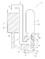
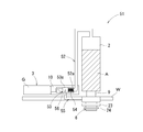
- FIG. 1 shows the concept of a sprinkler fire extinguishing device.
- the sprinkler fire extinguishing device 1 includes a main tank 2, a sub tank 3, a plug member 11 that functions as a trigger, a housing 7 that houses the plug member 11, and a temperature sensor.
- the main tank 2 is formed in a hollow cylindrical shape from metal (for example, aluminum) and has a volume of about 3.0 liters.
- An inlet 13 is provided at the upper end of the main tank 2, and the tip of a metal pipe 8 is connected to the inlet 13.
- a discharge port 14 is provided at the lower end, and a base end of a metal pipe 9 is connected to the discharge port 14.
- the main tank 2 is filled with about 2.0 liters of a fire extinguisher A (for example, a phosphate fire extinguisher in which a polysaccharide, phosphate, or the like is added to a surfactant). .
- a fire extinguisher A for example, a phosphate fire extinguisher in which a polysaccharide, phosphate, or the like is added to a surfactant.
- the sub tank 3 is formed of a metal (for example, aluminum) into a hollow cylindrical shape, and has a volume of about 500 ml (milliliter). Further, at the lower end of the sub-tank 3, a cylindrical discharge pipe 10 is formed to have a smaller diameter than other parts, and a discharge port 12 is provided at the tip (lower end) of the discharge pipe 10. Yes. The tip of the discharge pipe 10 is connected to the housing 7. The sub tank 3 is filled with compressed gas G (CO 2 ).
- CO 2 compressed gas
- the housing 7 is formed of a heat-resistant synthetic resin so as to have a substantially cylindrical outer shape.
- the internal space is partitioned into two chambers, a first chamber 7a and a second chamber 7b, by the partition plate 15.
- An insertion hole 16 is formed substantially at the center of the partition plate 15, and an axial center of a plug member 11 described later is inserted into the insertion hole 16.
- the first chamber 7a is provided with a gas inflow hole 17 and a gas discharge hole 18, which are connected to the discharge pipe 10 of the sub tank 3 and the base end of the pipe 8, respectively.
- the second chamber 7 b is provided with a fire extinguishing agent inflow hole 19 and a fire extinguishing agent discharge hole 20, and the extinguishing agent inflow hole 19 is connected to the tip of the pipe 9.
- the plug member 11 is formed in a substantially rod shape with metal, and a thick flange-shaped plug body 11b for closing the extinguishing agent discharge hole 20 of the housing 7 is provided at the lower end of the cylindrical shaft body 11a. It has been.
- the plug 11b is engaged with an outer plate 24 (described later) of the sprinkler head 6.
- a flange body 11c for closing the lower end of the gas inflow hole 17 of the housing 7 (the tip of the discharge pipe 10 of the sub tank 3) is provided at the upper end of the shaft body 11a, and above the flange body 11c.
- a protrusion 11d is formed.
- the protrusion 11d has a pointed tip, and an inclined surface is formed on one side (the side where the gas discharge port 18 is installed).
- the plug member 11 presses the flange body 11c against the lower end of the discharge pipe 10 of the sub tank 3, closes the discharge port 12 of the discharge pipe 10 with the projection 11d, and discharges the fire extinguishing agent of the housing 7 with the plug body 11b. It is installed in the housing 7 so that the hole 20 is closed.
- the sprinkler head 6 includes a main body 21, a frame 22, an inner plate 23, an outer plate 24, heat sensitive bodies 25, 25..., A fusible body 26, and a ring body 27.
- the deflector 28 and the like are assembled.
- the fusible body 26 functions as a temperature sensor, is formed of solder (an alloy mainly composed of lead and tin), and melts at a predetermined temperature (about 96 ° C.). .
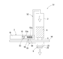
- the sprinkler fire extinguishing apparatus 1 configured as described above is installed and used in a building with the housing 7 placed on the upper side of the ceiling board and the sprinkler head 6 exposed from the ceiling board.
- the fusible body 26 as a temperature sensor melts at a predetermined temperature.
- the inner plate 23 and the outer plate 24 fall together as shown in FIG.
- the plug member 11 is pulled downward, so that the projection 11d of the plug member becomes the discharge pipe 10 of the sub tank 3. Since it falls off from the discharge port 12, the discharge port 12 is opened.
- the compressed gas G (CO 2 gas) in the sub-tank 3 is ejected at once and flows into the main tank through the pipe 8. Therefore, the extinguishing agent A in the main tank 2 is pressurized downward, and the pressure propagates to the second chamber 7b of the housing, so that the extinguishing agent A is rapidly (rapidly) from the extinguishing agent discharge hole 20 of the housing 7. Squirt.
- the deflector 28 (not shown) is lowered from the inside of the frame 22 as described above.
- the fire extinguishing agent A ejected from 20 hits the deflector 28 and diffuses and falls in all directions. Such a series of operations can effectively suppress the fire.
- the sprinkler fire extinguishing apparatus 1 includes the main tank 2 storing the fire extinguishing agent A, and the sprinkler head 6 connected to the main tank 2 and having a temperature sensor (the fusible body 26 of the sprinkler head 6).
- the temperature sensor detects a predetermined temperature (that is, when the fusible body 26 melts)
- the fire extinguishing agent A in the main tank 2 is released from the sprinkler head 6 to the outside.
- the sprinkler fire extinguishing apparatus 1 does not need to be provided with a long pipe connecting the water tank or the like and the sprinkler head unlike the conventional sprinkler fire extinguishing apparatus, and can be constructed inexpensively and easily. Moreover, even when the pipe 8 and the pipe 9 are not used for a long period of time, maintenance is easy because the pipe 8 and the pipe 9 are not easily rusted.
- the sprinkler fire extinguishing apparatus 1 includes a sub tank 3 filled with the compressed gas G and a trigger (plug member 11) for opening the sub tank 3.
- the trigger is Since the subtank 3 is opened in conjunction with the compressed gas G in the subtank 3 and flows into the main tank 2, the fire extinguishing agent A in the main tank 2 flows down to the sprinkler head 6. Since the fire extinguishing agent A in the main tank 2 can be released from the sprinkler head 6 within a short time by using the compressed gas G, it is possible to effectively prevent the situation where the fire spreads.
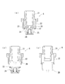
- FIG. 4 shows the concept of the sprinkler fire extinguishing device of the second embodiment.
- the sprinkler fire extinguishing device 31 is composed of the main tank 2, the sprinkler head 6 having a temperature sensor, the piping 9, and the like. And in the main tank 2, like the sprinkler fire extinguishing apparatus 1 of Example 1, while being filled with the fire extinguisher A, the compressed gas G was also filled and the fire extinguisher A was pressurized below. It is in a state.
- the main tank 2 is directly connected to the sprinkler head 6 by a metal pipe 9.
- the sprinkler fire extinguishing device 31 of the second embodiment is inexpensive and easy because it is not necessary to provide a long pipe for connecting a water tank or the like and the sprinkler head unlike the conventional sprinkler fire extinguishing device 1 as in the case of the sprinkler fire extinguishing device 1 of the first embodiment. Can be built. In addition, even when the pipe 9 is not used for a long period of time, maintenance is easy because the pipe 9 and the like are not easily rusted. Moreover, since the fire extinguisher A can be discharged from the sprinkler head 6 within a short time by using the compressed gas G in the main tank 2, it is possible to effectively prevent a fire from spreading.
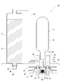
- FIG. 5 shows the concept of the sprinkler fire extinguishing device of the third embodiment.
- the sprinkler fire extinguishing device 41 includes a main tank 2, a sub tank 3, a valve (solenoid valve) 42 functioning as a trigger, and a sprinkler head having a temperature sensor. 6, a pipe 9, a second temperature sensor (fuse) 43, a signal line 44, a pipe 45, and the like.
- the structure of the main tank 2, the sub tank 3 and the sprinkler head 6 is the same as that of the sprinkler fire extinguishing device 1 of the first embodiment.
- the main tank 2 is filled with the fire extinguisher A, and the sub tank 3 is compressed. Gas G is filled.
- the main tank 2 is directly connected to the sprinkler head 6 through a metal pipe 9 as in the case of the sprinkler fire extinguishing device 31 of the second embodiment.
- a valve (electromagnetic valve) 42 is provided in the pipe 45 connecting the sub tank 3 and the main tank 2, and the valve 42 is connected to the second temperature sensor 43 by a signal line 44. It has become.
- the housing 7 is placed on the upper side of the ceiling plate W with the sprinkler head 6 exposed from the ceiling plate W, and the second temperature sensor 43 is connected to the sprinkler head. Installed in the building in the state of being placed in the vicinity of 6 and used.
- the fusible body 26, which is a temperature sensor of the sprinkler head 6, as in the sprinkler fire extinguishing apparatus 1 of the first embodiment As a result of melting at a predetermined temperature, the inner plate 23 and the outer plate 24 fall together and the tip of the sprinkler head 6 is opened.
- the fuse serving as the second temperature sensor 43 is blown, and a detection signal resulting from the cutting of the fuse is transmitted to the valve 42 via the signal line 44, Perform an open action.
- the valve 42 is thus opened, the compressed gas G in the sub-tank 3 is ejected at once and flows into the main tank 2 through the pipe 45. Therefore, the fire extinguisher A in the main tank 2 is pressurized downward, and is blown out from the tip of the sprinkler head 6 at a stretch, hits the deflector 28 and diffuses and falls in all directions. Such a series of operations can effectively suppress the fire.
- the sprinkler fire extinguishing device 41 of the third embodiment is a long pipe that connects a water tank or the like and the sprinkler head like the conventional sprinkler fire extinguishing device 31 like the sprinkler fire extinguishing device 1 of the first embodiment and the sprinkler fire extinguishing device 31 of the second embodiment. Since it is not necessary to provide it, it can be constructed inexpensively and easily. In addition, even when not used for a long period of time, the pipe 9 and the pipe 45 are not easily rusted, so that maintenance is easy.
- the sprinkler fire extinguishing device 41 uses the compressed gas G in the sub-tank 3 to remove the fire extinguishing agent A in the main tank 2 from the sprinkler head 6 within a short time, like the sprinkler fire extinguishing device 1 of the first embodiment. Since it can be made to discharge, the situation where a fire spreads can be prevented effectively. Further, in the sprinkler fire extinguishing device 41, the trigger for opening the sub tank 3 is the valve 42 electrically connected to the second temperature sensor 43. It can be effectively prevented.
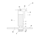
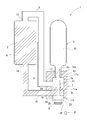
- FIG. 6 shows the concept of the sprinkler fire extinguishing apparatus of the fourth embodiment.
- the sprinkler fire extinguishing apparatus 51 includes a main tank 2, a sub tank 3, a sprinkler head 6 having a temperature sensor, the main tank 2 and the sprinkler head 6.
- the connecting pipe 9, the pipe 52, an opening member (cylinder pin) 53 that functions as a trigger, an urging member (coil spring) 54, and a fixing member 55 are configured.
- the structure of the main tank 2 and the sub tank 3 is the same as that of the sprinkler fire extinguisher 1 of the first embodiment.
- the main tank 2 is filled with the fire extinguishing agent A, and the sub tank 3 contains the compressed gas G. Filled.
- the main tank 2 is directly connected to the sprinkler head 6 through a metal pipe 9 as in the case of the sprinkler fire extinguishing device 31 of the second embodiment.
- the sub-tank 3 is filled with the compressed gas G as in the sprinkler fire extinguishing apparatus 1 of the first embodiment, but the tip of the discharge pipe 10 is a film body (for example, a metal film such as an aluminum foil or the like having a predetermined thickness). The film is covered (closed).
- the pipe 52 connecting the sub tank 3 and the main tank 2 is formed with a large diameter portion 52a. Inside the large diameter portion 52a, an opening member 53 and an urging member 54 functioning as a pin member are provided. Built in.
- the opening member 53 is made of metal, and the tip side is sharply pointed. Further, a support portion 53a is provided on the proximal end side of the opening member 53, and an insertion hole (not shown) is formed below the support portion 53a.
- a fixing member 55 is provided on the outer plate 24 of the sprinkler head 6 so as to protrude outward.
- the tip of the fixing member 55 is bent in an L shape, and a fixing pin 56 having a sharp tip is attached to the tip of a vertically rising portion.
- the fixing pin 56 is inserted into an insertion hole (not shown) of the support portion 53 a of the opening member 53, and the opening member 53 is fixed in a state where it is urged by the urging means 54.
- the fixing member 55 fixed to the outer plate 24 is also dropped together, so that the fixing pin 56 of the fixing member 55 is attached to the support portion 53a of the opening member 53. Remove from the insertion hole (not shown).
- the fixing pin 56 is thus detached from the opening member 53, the opening member 53 is pushed forward by the urging means 54, and the sharp tip breaks through the film body covering the opening of the sub tank 3, so that the sub tank 3 Is opened.
- the compressed gas G in the sub-tank 3 is ejected at a stroke and flows into the main tank via the pipe 8
- the extinguishing agent A in the main tank 2 is pressurized downward and from the tip of the sprinkler head 6 at a stroke. It blows out, hits the deflector 28, diffuses in all directions and falls. Such a series of operations can effectively suppress the fire.
- the sprinkler fire extinguishing device 51 is similar to the sprinkler fire extinguishing device 1 according to the first embodiment, the sprinkler fire extinguishing device 31 according to the second embodiment, and the sprinkler fire extinguishing device 41 according to the third embodiment. Since there is no need to provide a long pipe connecting the two, it can be constructed inexpensively and easily. In addition, since the pipe 9 and the pipe 52 are not easily rusted even when they are not used for a long period of time, maintenance is easy.
- the sprinkler fire extinguishing device 51 uses the compressed gas G in the sub tank 3 to apply the fire extinguishing agent A in the main tank 2 in the same manner as the sprinkler fire extinguishing device 1 in the first embodiment and the sprinkler fire extinguishing device 41 in the third embodiment. Since it can discharge
- the opening member 53 which is a pin member
- the biasing means 54 By pushing the opening member 53, which is a pin member, into the sub tank 3 by the biasing means 54, the compressed gas G in the sub tank 3 flows into the main tank 2, so that the trigger is surely activated in the event of a fire. It is possible to effectively prevent the fire from spreading.
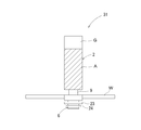
- FIG. 8 shows the concept of the sprinkler fire extinguishing device according to the fifth embodiment.
- the sprinkler fire extinguishing device 61 includes a main tank 2, a sub tank 3, a housing 62 equipped with a temperature sensor and a trigger, the main tank 2 and the housing 62.
- the pipe 63, the deflector 28, and the like are connected.
- the structure of the main tank 2 is the same as that of the sprinkler fire extinguishing device 1 of the first embodiment, and the main tank 2 is filled with a fire extinguishing agent A.
- a discharge part 64 having a smaller diameter than the other part is formed at the tip (lower end) of the main tank 2, and the tip of the discharge part 64 is a film body (for example, an aluminum foil or the like) having a predetermined thickness. It is covered with a metal film or film) 65 (closed).
- a deflector 28 similar to the sprinkler fire extinguishing device 1 of the first embodiment is fixed to the lower side of the discharge portion 64 of the main tank 2.
- the sub tank 3 is filled with the compressed gas G as in the case of the sprinkler fire extinguishing apparatus 1 of the first embodiment.
- the tip of the discharge pipe 10 provided at the lower end is covered with a film body (for example, a metal film or film such as an aluminum foil) 66 having a predetermined thickness, like the tip of the discharge part 64 of the main tank 2. It is in a state (closed state).
- the housing 62 is composed of an upper cylindrical body 67 and a lower cylindrical body 68 that are formed in a flat cylindrical shape with a heat-resistant synthetic resin, and a lid body 69 that is formed in a disk shape with a similar heat-resistant synthetic resin.
- the heat-sensitive bodies 70 and 71 and the fusible body 72 functioning as temperature sensors, the opening member (cylinder pin) 73 and the biasing member (coil spring) 75 functioning as a trigger are integrated using the screw members 74 and 74. Is installed.
- a gas flow path 76 is provided on the side surface of the upper cylindrical body 67, and a screw groove (not shown) is threaded on the lower surface. Further, two screw insertion holes (not shown) are formed in the lower cylinder body 68 and the lid body 69 so as to face each other.
- the opening member 73 has a shape in which a metal pointed tube 77 having a sharpened tip is projected from the upper surface of a flat columnar base 78.
- a gas discharge path 79 is formed so as to connect the inside of the pointed tube body 77 and the side surface of the base 78.
- the two heat sensitive bodies 70 and 71 are formed in a donut plate shape with a central portion raised by metal, and are drilled so that two screw insertion holes (not shown) face each other.
- the fusible body 72 is formed in a donut plate shape by a resin that melts at a predetermined temperature, and is drilled so that two screw insertion holes (not shown) face each other, like the heat sensitive bodies 70 and 71.
- the central hole of the fusible body 72 is slightly larger than the outer diameter of the pointed tube 77 of the opening member 73, and the central hole of the heat sensitive bodies 70, 71 is the base 78 of the opening member 73. It is slightly larger than the outer diameter.
- the housing 62 has the opening 69 and the urging member 75 accommodated in the cavity of the lower cylinder 68, and the lid 69 is brought into contact with the lower surface of the lower cylinder 68, so that the upper surface of the lower cylinder 68 In a state where the central portions of the two heat sensitive bodies 70 and 71 and the fusible body 72 are placed, the screw members 74 and the screw insertion holes of the lid 69, the lower cylindrical body 68, the heat sensitive bodies 70 and 71, and the fusible body 72 are provided.
- the opening member 73 When the fusible body 26 is thus melted, the opening member 73 is pushed upward by the biasing means 75, and the sharp tip of the pointed tube body 77 breaks through the film body 66 covering the discharge pipe 10 of the sub tank 3.
- the sub tank 3 is in an open state. Further, when the opening member 73 is pushed up, the gas discharge passage 79 brings the inside of the sub tank 3 into communication with the gas passage 76. Further, as described above, when the sub tank 3 is opened, the compressed gas G in the sub tank 3 is ejected at once and flows into the main tank 2 via the gas flow path 76 and the pipe 63. Is pressed downward with high pressure.
- the sprinkler fire extinguishing device 61 is similar to the conventional sprinkler fire extinguishing device 1, the sprinkler fire extinguishing device 31 of the second embodiment, the sprinkler fire extinguishing device 41 of the third embodiment, and the sprinkler fire extinguishing device 51 of the fourth embodiment.
- the pipe 63 and the like are not easily rusted, so that maintenance is easy.
- the sprinkler fire extinguishing device 61 uses the compressed gas G in the sub tank 3 in the same manner as the sprinkler fire extinguishing device 1 of the first embodiment, the sprinkler fire extinguishing device 41 of the third embodiment, and the sprinkler fire extinguishing device 51 of the fourth embodiment. Since the fire extinguisher A in the main tank 2 can be released within a short time, it is possible to effectively prevent a fire from spreading. Furthermore, the sprinkler fire extinguishing device 61 has an opening member 73 with a trigger pointed at the tip and an urging member 75, and when the temperature sensor (the heat sensitive bodies 70 and 71 and the fusible body 72) detects a predetermined temperature.
- the compressed gas G in the sub-tank 3 is caused to flow into the main tank 2 by piercing the sub-tank 3 with the opening member 73 (pointed tube 77), which is a pin member, by the biasing means 75. Therefore, it is possible to effectively prevent the trigger from operating reliably and spreading fire.
- the configuration of the sprinkler fire extinguishing apparatus according to the present invention is not limited to the above-described embodiments, and the configurations of the main tank, the sub tank, the trigger, the temperature sensor, the sprinkler head, and the like depart from the spirit of the present invention. As long as it is not necessary, it can be changed as needed.
- the sprinkler head is not limited to the one that detects the temperature by melting the fusible body as in the above embodiments, but can be changed to one that uses a thermocouple.
- the second temperature sensor is not limited to the fuse, and may be changed to one using the thermal expansion of the element or one using a thermocouple. Is also possible.
- the opening member is not limited to the one that is urged by the urging member, and can be changed to one that opens the sub tank by a solenoid or the like. is there.
- the fire extinguishing agent to be filled in the main tank of the sprinkler fire extinguishing apparatus according to the present invention is not limited to a phosphate-based one in which polysaccharides, phosphates, and the like are blended with a surfactant, and carbon dioxide by chemical reaction. It is also possible to change to those that generate water or those of potassium salt type. Furthermore, it is also possible to use a fire extinguishing agent mainly composed of potassium carbonate, which is effective for igniting tempura oil.
- the fire extinguishing ability of the fire extinguishing device will be greatly improved.
- the compressed gas filled in the sub tank is not limited to CO 2 and can be changed to other compressed gases.
- the sprinkler fire extinguishing apparatus is not limited to the one that automatically injects the fire extinguishing agent only when the temperature sensor detects that the temperature is high, as in the above-described embodiment.
- a manual switch (81) for ejecting a fire extinguisher may be provided.
- means for applying a force to the members (the inner plate 23 and the outer plate 24 in the above embodiment) covering the opening of the sprinkler, or a temperature sensor for the sprinkler Means or the like for supplying power to a member (heating wire or the like) that heats can be used.
- the sprinkler fire extinguishing apparatus includes a pipe connecting the main tank and the sprinkler head, a pipe connecting the main tank and the sub tank, a pipe connecting the sub tank and the sprinkler head, the main tank and the housing, as in the above embodiment.
- a pipe connecting the main tank and the sprinkler head a pipe connecting the main tank and the sub tank, a pipe connecting the sub tank and the sprinkler head, the main tank and the housing, as in the above embodiment.
- pipes made of metal pipes for connecting the pipes
- pipes made of synthetic resin such as rubber or vinyl chloride
- it is more preferable to use a pressure-resistant type for example, one whose outer periphery is covered with a net-like body formed of synthetic fiber or wire).
- the sprinkler fire extinguishing apparatus when the sprinkler fire extinguishing apparatus according to the present invention is provided with a sub-tank, it is not limited to a mode in which the sub-tank is disposed outside the main tank as in the above-described embodiment, but is a commercially available fire extinguisher. In addition, it is possible to arrange a sub tank in the main tank.
- the sprinkler fire extinguishing apparatus according to the present invention exhibits excellent effects as described above, it can be suitably used as a simple fire extinguishing apparatus that is permanently installed in various buildings.
Landscapes
- Health & Medical Sciences (AREA)
- Public Health (AREA)
- Business, Economics & Management (AREA)
- Emergency Management (AREA)
- Fire-Extinguishing By Fire Departments, And Fire-Extinguishing Equipment And Control Thereof (AREA)
Abstract
L'invention a pour but de proposer un dispositif d'extinction de feu sprinkler pratique qui a une structure simple, peut être fabriqué de façon peu coûteuse et facile, et est facile à entretenir. A cet effet, selon l'invention, un dispositif d'extinction de feu sprinkler (1) comprend un réservoir principal (2) qui stocke un agent d'extinction, et une tête de sprinkler (6) qui est connectée au réservoir principal (2) et a un capteur de température (élément fusible qui fond à une température prescrite). De plus, lorsque le capteur de température détecte la température prescrite (en d'autres termes, lorsque l'élément fusible fond), un agent d'extinction (A) dans le réservoir principal (2) est déchargé à partir de la tête de sprinkler (6) vers l'extérieur.
Priority Applications (1)
| Application Number | Priority Date | Filing Date | Title |
|---|---|---|---|
| JP2014526313A JP5759631B2 (ja) | 2013-04-09 | 2014-04-08 | スプリンクラー消火装置 |
Applications Claiming Priority (2)
| Application Number | Priority Date | Filing Date | Title |
|---|---|---|---|
| JP2013-081393 | 2013-04-09 | ||
| JP2013081393 | 2013-04-09 |
Publications (1)
| Publication Number | Publication Date |
|---|---|
| WO2014168156A1 true WO2014168156A1 (fr) | 2014-10-16 |
Family
ID=51689562
Family Applications (1)
| Application Number | Title | Priority Date | Filing Date |
|---|---|---|---|
| PCT/JP2014/060226 WO2014168156A1 (fr) | 2013-04-09 | 2014-04-08 | Dispositif d'extinction de feu sprinkler |
Country Status (2)
| Country | Link |
|---|---|
| JP (2) | JP5759631B2 (fr) |
| WO (1) | WO2014168156A1 (fr) |
Cited By (4)
| Publication number | Priority date | Publication date | Assignee | Title |
|---|---|---|---|---|
| WO2017163401A1 (fr) * | 2016-03-25 | 2017-09-28 | 株式会社J-Style | Procédé de production d'agent d'extinction d'incendie |
| JP6219476B1 (ja) * | 2016-10-03 | 2017-10-25 | 日本ファイヤープロテクト株式会社 | 簡易型自動消火器 |
| CN117653978A (zh) * | 2023-12-11 | 2024-03-08 | 兴化市方圆消防器材有限公司 | 一种变容式泡沫灭火消防栓 |
| CN117653978B (zh) * | 2023-12-11 | 2024-05-28 | 兴化市方圆消防器材有限公司 | 一种变容式泡沫灭火消防栓 |
Citations (5)
| Publication number | Priority date | Publication date | Assignee | Title |
|---|---|---|---|---|
| JPS5490097U (fr) * | 1977-12-09 | 1979-06-26 | ||
| JPH09510123A (ja) * | 1994-03-09 | 1997-10-14 | ローボン ピアース | 消火装置 |
| JP2002224238A (ja) * | 2001-02-06 | 2002-08-13 | Senju Sprinkler Kk | スプリンクラー消火設備 |
| WO2003043700A1 (fr) * | 2001-11-20 | 2003-05-30 | Kazuo Aoki | Extincteur automatique |
| JP2012152388A (ja) * | 2011-01-26 | 2012-08-16 | Asahi Gakuen Group:Kk | 初期消火装置 |
Family Cites Families (3)
| Publication number | Priority date | Publication date | Assignee | Title |
|---|---|---|---|---|
| JPS5617055Y2 (fr) * | 1977-04-06 | 1981-04-21 | ||
| JPS5618129Y2 (fr) * | 1977-12-28 | 1981-04-27 | ||
| JP2890097B2 (ja) * | 1994-05-24 | 1999-05-10 | 松本 勝俊 | 簡易手動消火ガス噴射器具 |
-
2014
- 2014-04-08 WO PCT/JP2014/060226 patent/WO2014168156A1/fr active Application Filing
- 2014-04-08 JP JP2014526313A patent/JP5759631B2/ja active Active
-
2015
- 2015-03-20 JP JP2015057325A patent/JP6430308B2/ja active Active
Patent Citations (5)
| Publication number | Priority date | Publication date | Assignee | Title |
|---|---|---|---|---|
| JPS5490097U (fr) * | 1977-12-09 | 1979-06-26 | ||
| JPH09510123A (ja) * | 1994-03-09 | 1997-10-14 | ローボン ピアース | 消火装置 |
| JP2002224238A (ja) * | 2001-02-06 | 2002-08-13 | Senju Sprinkler Kk | スプリンクラー消火設備 |
| WO2003043700A1 (fr) * | 2001-11-20 | 2003-05-30 | Kazuo Aoki | Extincteur automatique |
| JP2012152388A (ja) * | 2011-01-26 | 2012-08-16 | Asahi Gakuen Group:Kk | 初期消火装置 |
Cited By (4)
| Publication number | Priority date | Publication date | Assignee | Title |
|---|---|---|---|---|
| WO2017163401A1 (fr) * | 2016-03-25 | 2017-09-28 | 株式会社J-Style | Procédé de production d'agent d'extinction d'incendie |
| JP6219476B1 (ja) * | 2016-10-03 | 2017-10-25 | 日本ファイヤープロテクト株式会社 | 簡易型自動消火器 |
| CN117653978A (zh) * | 2023-12-11 | 2024-03-08 | 兴化市方圆消防器材有限公司 | 一种变容式泡沫灭火消防栓 |
| CN117653978B (zh) * | 2023-12-11 | 2024-05-28 | 兴化市方圆消防器材有限公司 | 一种变容式泡沫灭火消防栓 |
Also Published As
| Publication number | Publication date |
|---|---|
| JPWO2014168156A1 (ja) | 2017-02-16 |
| JP5759631B2 (ja) | 2015-08-05 |
| JP6430308B2 (ja) | 2018-11-28 |
| JP2015110124A (ja) | 2015-06-18 |
Similar Documents
| Publication | Publication Date | Title |
|---|---|---|
| US10398915B2 (en) | Extinguishing method and system using a liquid synthetic extinguishing agent and water | |
| JP6449313B2 (ja) | 消火システム | |
| US8863856B2 (en) | Methods and apparatus for multi-stage fire suppression | |
| US20170120089A1 (en) | Methods and apparatus for fire suppression system for transportable container | |
| KR102026969B1 (ko) | 자동으로 작동되는 소화기 | |
| KR101355831B1 (ko) | 소방용 소화장치 | |
| JP6430308B2 (ja) | スプリンクラー消火装置 | |
| KR20120134353A (ko) | 소방기기의 스마트 헤드 자동작동장치 | |
| KR200447990Y1 (ko) | 자동확산 소화기 | |
| KR100943440B1 (ko) | 무인 자동 소화기 | |
| JP4511229B2 (ja) | 消火システム及び消火装置 | |
| CN203842219U (zh) | 一种机柜气体灭火装置 | |
| KR102551905B1 (ko) | 자동 및 수동 겸용 소화장치 | |
| US20210260419A1 (en) | Dry drop for a fire extinction vacuum network | |
| KR101328815B1 (ko) | 유리벌브 파열장치 | |
| JP2015110124A5 (fr) | ||
| JP2010184000A (ja) | スプリンクラ消火設備及びこのスプリンクラ消火設備に使用されるスプリンクラヘッド | |
| CN219558577U (zh) | 一种单模启动闭式喷头 | |
| JP2007159916A (ja) | 消火装置及び消火装置用感熱ノズル | |
| CN219743764U (zh) | 机械式自动灭火装置 | |
| CN220070579U (zh) | 一种间接启动的灭火装置 | |
| JP2011120670A (ja) | スプリンクラーヘッド | |
| CN212466927U (zh) | 一种易燃易爆工房用新型快速灭火装置 | |
| KR100832857B1 (ko) | 면상발열체를 사용한 기폭장치 및 이를 구비한 소화기구의기동용 헤드 | |
| CN219896894U (zh) | 机械式自动分区灭火装置 |
Legal Events
| Date | Code | Title | Description |
|---|---|---|---|
| ENP | Entry into the national phase |
Ref document number: 2014526313 Country of ref document: JP Kind code of ref document: A |
|
| 121 | Ep: the epo has been informed by wipo that ep was designated in this application |
Ref document number: 14782730 Country of ref document: EP Kind code of ref document: A1 |
|
| NENP | Non-entry into the national phase |
Ref country code: DE |
|
| 122 | Ep: pct application non-entry in european phase |
Ref document number: 14782730 Country of ref document: EP Kind code of ref document: A1 |