WO2014168133A1 - 切削加工方法及び切削加工装置 - Google Patents
切削加工方法及び切削加工装置 Download PDFInfo
- Publication number
- WO2014168133A1 WO2014168133A1 PCT/JP2014/060157 JP2014060157W WO2014168133A1 WO 2014168133 A1 WO2014168133 A1 WO 2014168133A1 JP 2014060157 W JP2014060157 W JP 2014060157W WO 2014168133 A1 WO2014168133 A1 WO 2014168133A1
- Authority
- WO
- WIPO (PCT)
- Prior art keywords
- cutting
- optical member
- face
- polarizer
- cutting blade
- Prior art date
- Legal status (The legal status is an assumption and is not a legal conclusion. Google has not performed a legal analysis and makes no representation as to the accuracy of the status listed.)
- Ceased
Links
Images


Classifications
-
- B—PERFORMING OPERATIONS; TRANSPORTING
- B23—MACHINE TOOLS; METAL-WORKING NOT OTHERWISE PROVIDED FOR
- B23C—MILLING
- B23C3/00—Milling particular work; Special milling operations; Machines therefor
- B23C3/12—Trimming or finishing edges, e.g. deburring welded corners
Definitions
- the present invention relates to a cutting method and a cutting apparatus.
- This application claims priority based on Japanese Patent Application No. 2013-81215 filed on April 9, 2013 and Japanese Patent Application No. 2013-1000074 filed on May 10, 2013, and the contents thereof. Is hereby incorporated by reference.
- Patent Document 1 Conventionally, as a cutting method for cutting an end face of an optical member such as a polarizing plate, a cutting method described in Patent Document 1 is known.
- a cutting region formed by a rotating cutting blade is brought into contact with an end surface of an optical member to perform cutting, a portion away from a predetermined imaginary line in the cutting region is selected. It is made to contact the end surface of an optical member. According to this method, it is described that the pressing action by the cutting blade is alleviated and the end face of the optical member can be finished in a good state.
- the polarizing plate is also made thin.
- a polarizing plate (hereinafter sometimes referred to as a thin polarizing plate) from which one TAC has been removed from triacetyl cellulose (TAC: TriAcetyl Cellulose) serving as a protective layer laminated on both surfaces of a polarizer has been developed.
- TAC TriAcetyl Cellulose
- the aspect of the present invention has been made in view of such circumstances, and an object thereof is to provide a cutting method and a cutting apparatus capable of finishing an end face of an optical member in a good state.
- the cutting method according to the first aspect of the present invention includes a polarizer, a first polarizer protective layer laminated on the first surface of the polarizer, and a second of the polarizer.
- a cutting method for cutting an end face of an optical member comprising a second polarizer protective layer laminated on a surface and having a Young's modulus lower than that of the first polarizer protective layer, the rotating shaft; Preparing a cutting member having a cutting blade projecting toward the end face side of the optical member; and protecting the first polarizer from the second polarizer protective layer side with the cutting blade centered on the rotation axis.
- Rotating to the side of the layer cutting the end face of the optical member by intruding the rotating cutting blade from the side of the second polarizer protective layer and bringing it into contact with the end face of the optical member; including.
- an optical member obtained by measuring the external dimensions of the optical member after cutting after the completion of one batch of cutting processing and obtaining the next batch by cutting processing. Before starting the next batch cutting process, adjust the relative position between the end face of the optical member to be processed in the next batch and the cutting blade so that the outer dimensions of the optical disk are within the required allowable range. May be.
- the cutting condition of the optical member is determined based on the result of a heat shock test.
- the heat shock test the optical member after cutting is processed.
- the optical member is heated at 60 ° C. to 90 ° C. for 1 hour, and the bonded body is left at room temperature for 15 to 30 minutes.
- the bonded body is placed in a water bath at a water temperature of 23 ° C. to 40 ° C. for 30 minutes. It may be immersed.
- a cutting device is a cutting device that cuts the end face of an optical member, and includes a rotary shaft and a cutting blade that protrudes toward the end face of the optical member. Then, the cutting blade is rotated about the rotation axis, and the cutting member that cuts the end surface of the optical member by bringing the rotating cutting blade into contact with the end surface of the optical member; A cover disposed so as to surround; and a suction device that sucks chips generated by cutting by sucking an inner portion of the cover.
- a scattering prevention brush for adhering the chips may be provided at an edge of the opening of the cover that exposes the cutting member.
- the cutting apparatus further including a moving device that relatively moves the cutting member in parallel with respect to an end surface of the optical member, and the cutting member and the optical member by the moving device;
- the anti-scattering brush may be brought into contact with the end face of the optical member by relative movement of the optical member, so that the chips attached to the end face of the optical member may be peeled off.
- (A) to (e) are explanatory diagrams of a peel test. It is a flowchart of a heat shock test. It is a perspective view of the 1st processing device concerning a 3rd embodiment. It is a top view of the 1st processing device concerning a 3rd embodiment. It is a figure for demonstrating the effect
- FIG. 1 is a perspective view showing a cutting apparatus 1 according to the first embodiment of the present invention.
- the cutting apparatus 1 is an apparatus for cutting an end face of an optical member.
- the end surface Wa of the rectangular parallelepiped laminated body W in which a plurality of optical members are stacked is set as a cutting target.
- the laminated body W is obtained by punching a long monolayer sheet or a raw sheet of a laminated sheet into a rectangular shape.
- the cutting target is not limited to the laminated body W, and may be a single optical member.
- Examples of the sheet constituting the laminate W include, but are not particularly limited to, a polyvinyl alcohol film, a cellulose film typified by a triacetyl cellulose film, and an ethylene-vinyl acetate film. Since the polarizing plate composed of a plurality of optical films is thick, it is preferable as a cutting target of the cutting apparatus 1 according to the first embodiment of the present invention capable of processing an end face of a large amount of films.
- the cutting device 1 includes a first processing device 2, a second processing device 3, a moving device 4, a first position adjusting device 5, a second position adjusting device 6, and a control device. 7.
- the first processing device 2 and the second processing device 3 are arranged to face each other with the moving device 4 interposed therebetween.
- a cutting member 20 that cuts the end surface Wa of the stacked body W is disposed on the side of the moving device 4 in the first processing device 2.
- a cutting member 20 that cuts the end surface Wa of the stacked body W is disposed on the side of the moving device 4 in the second processing device 3.
- FIG. 2 is a side view of the cutting member 20.
- the cutting member 20 includes a rotating shaft 21 extending along the normal direction of the end surface Wa (see FIG. 1) of the stacked body W, and a rotating body 22 that rotates about the rotating shaft 21. , A support base 23 that supports the rotating shaft 21, and a plurality of cutting blades provided on the rotating body 22 (for example, in the present embodiment, a first cutting blade 24a, a second cutting blade 24b, a third cutting blade 24c, a fourth cutting blade). 6 cutting blades of a blade 24d, a fifth cutting blade 24e, and a sixth cutting blade 24f).
- cutting blade 24 the first cutting blade 24a, the second cutting blade 24b, the third cutting blade 24c, the fourth cutting blade 24d, the fifth cutting blade 24e, and the sixth cutting blade 24f are collectively referred to as “cutting blade 24”. May be called.
- the rotating body 22 is fixed to the rotating shaft 21 and rotates in one direction around the rotating shaft 21.
- the rotating body 22 has an installation surface 22 a that is perpendicular to the rotating shaft 21.
- the rotary body 22 is a disk shape, it is not limited to this shape.
- the diameter of the rotating body 22 is about 250 mm.
- the diameter of the rotary body 22 is not restricted to this, For example, it can be 150 mm or more and 600 mm or less.
- the cutting blade 24 is provided on the installation surface 22 a of the rotating body 22.
- the cutting blade 24 protrudes from the installation surface 22a toward the end surface Wa (see FIG. 1) of the stacked body W.
- the cutting blades 24a to 24c have a larger amount of protrusion from the installation surface 22a in this order.
- the first cutting blade 24a has the longest distance from the rotating shaft 21 and the smallest protrusion amount from the installation surface 22a.
- the third cutting blade 24c has the shortest distance from the rotating shaft 21 and the largest protrusion amount from the installation surface 22a.
- the first cutting blade 24a, the second cutting blade 24b, the fourth cutting blade 24d, and the fifth cutting blade 24e are cutting blades for rough cutting, and are made of polycrystalline diamond.
- the third cutting blade 24c and the sixth cutting blade 24f are finishing cutting blades made of single crystal diamond.
- the material is selected as a preferable form as the material of the cutting blade, and is not limited to these as long as it is a material suitable for cutting the end surface Wa (see FIG. 1) of the laminated body W.
- the number of cutting blades is six.
- the number of cutting blades is not limited to this, and can be changed as appropriate according to various conditions such as the distance from the rotary shaft 21 to the cutting blade.
- positioning of the cutting blade is not specifically limited, From a viewpoint of processing efficiency, it is preferable that several cutting blades are arrange
- the shape of the cutting blade is not particularly limited, and may be a columnar shape, a prismatic shape, a columnar shape having a trapezoidal cross section, a hemispherical shape, or the like.
- the shape and size of the cutting blade can be appropriately set depending on the dimensions of the optical member, the required processing efficiency, and the like.
- the cutting blade may be inclined with respect to the axial direction of the rotating shaft 21 as long as it is provided so as to protrude toward the end face Wa (see FIG. 1) of the laminated body W.
- the moving device 4 includes a base 40, a portal frame 41 provided on the base 40, a disk-like table 42 provided on the base 40, and a table 42.
- the first pressing member 43 arranged, a cylinder 44 provided on the base 40 side of the frame 41, and a second pressing member 45 attached to the tip of the rod of the cylinder 44 are provided.
- the moving device 4 moves the laminate W with respect to the cutting member 20 in a direction V parallel to the longitudinal direction of the end surface Wa of the laminate W.
- the table 42 can rotate the first pressing member 43 around the central axis of the table 42.
- the cylinder 44 can move the second pressing member 45 up and down.
- the stacked body W is sandwiched and fixed between the first pressing member 43 and the second pressing member 45.
- the base 40 is movable so as to pass between the first processing device 2 and the second processing device 3.
- the laminated body W is fixed by the first pressing member 43 and the second pressing member 45.
- the normal direction of both end faces of the laminated body W and the extending direction of the rotating shaft 21 of each of the first processing device 2 and the second processing device 3 are matched.
- the rotary body 22 is rotated and the base 40 is moved so that the laminated body W may pass between the 1st processing apparatus 2 and the 2nd processing apparatus 3.
- the base 40 is moved in a direction V parallel to the longitudinal direction of the end surface Wa of the stacked body W to be cut by a moving mechanism (not shown). With the rotation of the rotating body 22, the cutting blade 24 provided on the installation surface 22 a of the rotating body 22 rotates and the cutting blade 24 comes into contact with the end surface Wa of the stacked body W, thereby cutting the end surface Wa.
- the first cutting blade 24a and the fourth cutting blade 24d located on the outermost side of the rotating body 22 are in contact with the stacked body W, and the end surface Wa of the stacked body W is cut.
- the second cutting blade 24b and the fifth cutting blade 24e provided on the inner side of the first cutting blade 24a and the fourth cutting blade 24d are in contact with the stacked body W, and the end surface of the stacked body W Wa is cut. Since the 2nd cutting blade 24b and the 5th cutting blade 24e have a larger projection amount than the 1st cutting blade 24a and the 4th cutting blade 24d, end face Wa cut by the 1st cutting blade 24a and the 4th cutting blade 24d, Cut deeper.
- the 1st cutting blade 24a, the 2nd cutting blade 24b, the 4th cutting blade 24d, and the 5th cutting blade 24e cut the end surface Wa of the laminated body W gradually deeply.
- the third cutting blade 24c and the sixth cutting blade 24f for finishing cut the end surface Wa of the laminated body W and perform mirror finishing.
- the first position adjusting device 5 is a device for adjusting the position of the first processing device 2.
- the first position adjusting device 5 of the present embodiment moves the first processing device 2 only in the direction Vf parallel to the short direction of the optical member F constituting the stacked body W.
- the second position adjusting device 6 is a device for adjusting the position of the second processing device 3.
- the second position adjusting device 6 of the present embodiment moves the second processing device 3 only in the direction Vf.
- the control device 7 comprehensively controls the first position adjusting device 5 and the second position adjusting device 6.
- the control device 7 of the present embodiment controls the first position adjusting device 5 and the second position adjusting device 6 to move each of the first processing device 2 and the second processing device 3 only in the direction Vf.
- FIG. 3 is a cross-sectional view of the optical member Fx of the comparative example.
- FIG. 4 is a cross-sectional view of the optical member F of the present embodiment. For convenience of illustration, hatching of each layer in FIGS. 3 and 4 is omitted.
- the optical member Fx of the comparative example includes a film-like optical member main body F1x, a retardation plate F4x provided on one surface (upper surface in FIG. 3) of the optical member main body F1x, and a phase difference.
- An adhesive layer F5x provided on the upper surface of the plate F4x, a separator F6x that is detachably stacked on the upper surface of the retardation plate F4x via the adhesive layer F5x, and the other surface of the optical member body F1a (the lower surface in FIG. 3)
- a surface protective film F7x laminated on the substrate The optical member body F1x functions as a polarizing plate.
- the optical member body F1x includes a polarizer F2x and a protective film F3x laminated on both sides of the polarizer F2x.
- the polarizer F2x is made of polyvinyl alcohol (PVA: Poly Vinyl Alcohol).
- the protective film F3x is made of triacetyl cellulose (TAC: TriAcetyl Cellulose).
- the optical member F of the present embodiment includes a film-like optical member main body F1, a retardation plate F4 provided on one surface (upper surface in FIG. 4) of the optical member main body F1, and a position.
- the optical member main body F1 functions as a polarizing plate.
- the optical member body F1 includes a polarizer F2 and a protective film F3 laminated on one surface (the lower surface in FIG. 4) of the polarizer F2.
- the protective film F3 is TAC.
- the protective film F3 corresponds to a first polarizer protective layer.
- the retardation film F4 corresponds to a second polarizer protective layer.
- an aqueous solution system, an organic solvent solution system, no It may be adhered by an appropriate adhesive such as a solvent type.
- the bonding of the protective film F3x and the retardation plate F4x in the comparative example and the bonding of the polarizer F2 and the retardation plate F4 in the present embodiment may be bonded with a pressure sensitive adhesive.
- the retardation plate F4 (second polarizer protective layer) may be a pressure-sensitive adhesive. it can.
- the optical member body F1 of the present embodiment removes the protective film F3x laminated on the upper surface of the polarizer F2x out of the protective film F3x laminated on both surfaces of the polarizer F2x with respect to the optical member body F1x of the comparative example. It has been configured. Therefore, the optical member main body F1 of the present embodiment is thinner than the optical member main body F1x of the comparative example by the protective film F3x.
- the optical member main body F1 of this embodiment may be referred to as a thin polarizing plate.
- the occurrence of cracks on the end face of the optical member may change when the penetration direction of the rotary blade is changed.
- the hardness differs between the protective layer laminated on one surface of the polarizer and the protective layer laminated on the other surface. Therefore, depending on whether the rotary blade enters the optical member from above or from below, the state of occurrence of cracks on the end face of the optical member varies depending on whether the polarizer is sufficiently protected or not protected. The inventor found out that the present invention was reached. Hereinafter, the cutting method according to the present embodiment will be described.
- the cutting method according to the present embodiment is a cutting method for an end surface Wa (see FIG. 1) of a laminated body W in which a plurality of optical members are stacked, and the cutting device 1 shown in FIGS. 1 and 2 is used. Done.
- FIG. 5 is a diagram for explaining the cutting method according to the present embodiment.
- FIG. 5 illustrates a cutting method in the case where the retardation plate F4 is disposed on the upper side with respect to the polarizer F2.
- the upper part of FIG. 5 is a diagram showing cutting of the end surface Wa of the multilayer body W by the cutting member 20.
- the middle part of FIG. 5 is an enlarged end view of the laminated body W in the upper part of FIG.
- the lower part of FIG. 5 is a side view of the optical member F constituting the laminated body W in the middle part of FIG.
- the cutting method according to the present embodiment is performed by moving the rotating body 22 in the direction V parallel to the longitudinal direction of the end surface Wa of the stacked body W while rotating the rotating body 22 clockwise.
- the end surface Wa of the body W is cut.
- the laminated body W is formed by laminating a plurality of optical members F.
- the retardation film F4 is disposed on the upper surface of the polarizer F2.
- retardation plates F4, polarizers F2, and protective films F3 are alternately arranged in this order for each optical member F from the upper layer side to the lower layer side. ing.
- Table 1 is a table showing the Young's modulus [N / mm 2 ] of the retardation film and TAC (protective film).
- MD is the Young's modulus in the longitudinal direction (Machine Direction) of the transport sheet
- TD is the Young's modulus in the short direction (Transverse Direction) of the transport sheet.
- the conveyance sheet means a long sheet before the optical member is punched into a rectangular shape.
- the Young's modulus was measured based on No. 1 test piece of JIS K 7127 “Plastic film and sheet tensile test method”. Specifically, a test piece of width 10 mm ⁇ length 200 mm was cut out from the retardation film, the distance between the marked lines was set to 100 mm, and this was set in a universal testing machine “Autograph AG-I” manufactured by Shimadzu Corporation. A tensile test was performed at a tensile speed of 50 mm / min to obtain a Young's modulus. The tensile test was performed for each of the test piece cut out with the machine direction (length direction, MD) of the long roll film as the long side and the test piece cut out with the width direction (TD) of the long roll film as the long side. .
- MD machine direction
- TD width direction
- the Young's modulus of the retardation plate is lower than that of TAC.
- Young's modulus in MD is lower than that in TD.
- the lower data that is, the Young's modulus in MD is used.
- the inventor has entered the rotating cutting blade 24 from the side of the retardation plate F4 having a Young's modulus lower than that of the protective film F3, whereby the polarizer F2 is sufficiently protected and the optical member F
- the inventors have found that the occurrence of cracks on the end face Fa can be suppressed, and have invented the following cutting method.
- the cutting method according to the present embodiment includes a polarizer F2, a protective film F3 laminated on the lower surface of the polarizer F2, and a lower Young's modulus than the protective film F3, laminated on the upper surface of the polarizer F2.
- a cutting method for cutting an end face Fa of an optical member F including a phase difference plate F4, the rotating shaft 21 extending along a normal direction of the end face Fa of the optical member F, and an end face Fa of the optical member F The cutting member 20 having a cutting blade 24 protruding to the side is prepared, and the cutting blade 24 that rotates by rotating the cutting blade 24 from the phase difference plate F4 side to the protective film F3 side about the rotation shaft 21.
- the end surface Fa of the optical member F is cut by allowing the end plate 24 to enter from the side of the phase difference plate F4 and contact the end surface Fa of the optical member F.
- the rotating direction of the rotating body 22 is not limited to the direction shown in FIG. 5 (clockwise), but may be counterclockwise as shown in FIG.
- FIG. 6 is a diagram for explaining another example of the cutting method according to the present embodiment.
- FIG. 6 illustrates a cutting method in the case where the retardation plate F4 is disposed on the lower side with respect to the polarizer F2.
- the upper part of FIG. 6 is a diagram showing cutting of the end surface Wa of the multilayer body W by the cutting member 20.
- the middle part of FIG. 6 is an enlarged end view of the laminated body W in the upper part of FIG.
- the lower part of FIG. 6 is a side view of the optical member F constituting the laminated body W in the interruption of FIG.
- the cutting method according to the present embodiment moves the rotating body 22 in the direction V parallel to the longitudinal direction of the end face of the stacked body W while rotating the rotating body 22 counterclockwise.
- the end face Wa of W is cut.
- the laminated body W is formed by laminating a plurality of optical members F.
- the phase difference plate F4 is disposed on the lower surface of the polarizer F2.
- retardation plates F ⁇ b> 4, polarizers F ⁇ b> 2, and protective films F ⁇ b> 3 are alternately arranged in this order for each optical member F from the lower layer side to the upper layer side. ing.
- the polarizer F2 is sufficiently obtained by allowing the rotating cutting blade 24 to enter from the side of the retardation plate F4 having a Young's modulus lower than that of the protective film F3.
- the generation of cracks at the end face Fa of the optical member F can be suppressed.
- the polarizer F2 is sufficiently protected by allowing the rotating cutting blade 24 to enter from the side of the retardation plate F4 having a Young's modulus lower than that of the protective film F3, and the laminate. Generation of cracks on the end face Wa of W can be suppressed. Therefore, the end surface Wa of the stacked body W can be finished in a good state.
- the moving device 4 has been described by taking an example in which the stacked body W is moved in the direction V parallel to the longitudinal direction of the end surface Wa of the stacked body W with respect to the cutting member 20, but the present invention is not limited thereto.
- the moving device may move the cutting member in a direction parallel to the longitudinal direction of the end face of the laminate relative to the end face of the laminate. That is, the moving device may be configured to move the cutting member relative to the end surface of the laminate in a direction parallel to the longitudinal direction of the end surface of the laminate.
- FIG. 7 is a perspective view showing the cutting apparatus 1 according to the present embodiment.
- the same reference numerals are given to components common to the first embodiment, and detailed description thereof is omitted.
- the cutting apparatus 1 of the present embodiment has the same configuration as the cutting apparatus 1 of the first embodiment.
- a two-dimensional measuring machine 8 is disposed in the vicinity of the cutting apparatus 1.
- the two-dimensional measuring machine 8 measures the two-dimensional coordinates of the end surface Wa of the laminated body W in a non-contact manner with the image taken by a camera (not shown) and the position information of the XY stage.
- the two-dimensional measuring machine 8 measures the long side and the short side of the optical member F in the plane of the end surface Wa of the stacked body W (the upper portion of the end surface Wa, the central portion of the end surface Wa, and the lower portion of the end surface Wa). To do.
- the control device 7 controls the first position adjusting device 5 and the second position adjusting device 6 based on the measurement result of the two-dimensional measuring machine 8, and each of the first processing device 2 and the second processing device 3 is Move only in the direction Vf.
- the cutting method according to the present embodiment is performed using the cutting device 1 and the two-dimensional measuring machine 8 shown in FIG.
- the cutting method according to the present embodiment moves the rotating body 22 in the direction V parallel to the longitudinal direction of the end surface Wa of the stacked body W while rotating the rotating body 22 clockwise.
- the end surface Wa is cut.
- the allowable range of the product standard is wide.
- the tolerance of the outer dimension of the polarizing plate is ⁇ 0.15 mm. Therefore, the change width of the outer dimension of the polarizing plate at the time of cutting the end face of the polarizing plate is within the allowable range of the product standard, and a polarizing plate satisfying the required dimension can be obtained.
- the demand for the change width of the outer dimension of the polarizing plate has become stricter. And it is +0.05 mm or less. Therefore, if the end face of the polarizing plate is simply cut, the change width of the outer dimensions of the polarizing plate at the time of cutting exceeds the allowable range of the product standard, and it becomes difficult to satisfy recent strict required dimensions. ing.
- the present inventor has found that the above problem is that when the rotating body 22 is rotated for a predetermined time, thermal expansion is caused by the rotational drive of the rotating shaft 21 and the friction between the rotating shaft 21 and a bearing (not shown). As a result, it was found that a polarizing plate satisfying the required dimensions can be obtained by moving the set position of the cutting member 20 at a predetermined timing, and the following cutting method was invented. .
- the cutting method measures the outer dimensions of the laminated body W after cutting after the completion of one batch of the cutting process, and the outer dimensions of the laminated body W obtained by the cutting process of the next batch.
- the stack is processed in the next batch before starting the next batch.
- the relative position between the end surface Wa of the body W and the cutting blade 24 is adjusted.
- one batch means a process of cutting each of the four end faces Wa of one laminate W once. For example, when two end surfaces Wa of the four end surfaces Wa of the laminated body W are simultaneously cut at once, first, the two end surfaces Wa of the laminated body W in the longitudinal direction of the optical member F are cut, and then By rotating the table 42 by 90 ° and cutting the remaining two end faces Wa of the laminated body W in the short direction of the optical member F, one batch is completed.
- FIG. 8 is a diagram showing a change in the outer dimension of the laminated body W in the long side direction of the optical member F.
- FIG. 9 is a diagram showing a change in the outer dimension of the laminated body W in the short side direction of the optical member F.
- the horizontal axis represents the number of batches [times].
- the vertical axis represents the deviation [mm] from the reference value of the outer dimension of the laminated body W in the long side direction of the optical member F.
- the vertical axis represents the deviation [mm] from the reference value of the outer dimension of the laminated body W in the short side direction of the optical member F.
- “upper” is the measurement result of the upper portion of the end surface Wa of the stacked body W
- “middle” is the measurement result of the center portion of the end surface Wa of the stacked body W
- “lower” is the stacked body. It is a measurement result of the lower part of the end surface Wa of W.
- the laminated body W of the optical member F in each of the long side direction and the short side direction is increased as the number of batches is increased.
- the amount of deviation from the reference value of the outer dimension increases. Therefore, if the number of batches is continuously increased as it is, the change width of the outer dimension of the polarizing plate during the cutting process exceeds the allowable range of the product standard (for example, the outer dimension tolerance of the polarizing plate: ⁇ 0.03 mm).
- the outer dimension of the laminated body W in each of the long-side direction and the short-side direction of the optical member F is set as the outer dimension of the laminated body W after the cutting process after one cutting process batch is completed.
- the next batch is measured so that the outer dimensions of the laminate W obtained by the cutting processing of the next batch do not exceed the required allowable range (for example, the outer dimension tolerance of the polarizing plate: ⁇ 0.03 mm).
- the relative position between the end surface Wa of the laminate W to be cut in the next batch and the cutting blade 24 is adjusted.
- the set position of the cutting member 20 is moved in a direction that cancels out the deviation amount. In each of the long side direction and the short side direction, the amount of deviation from the reference value of the outer dimension of the laminated body W is prevented from exceeding the allowable range, and the required dimension is satisfied.
- the optical member F that satisfies the required dimensions can be obtained by moving the set position of the cutting member 20 at a predetermined timing.
- the two-dimensional measuring machine 8 by measuring the long side and the short side of the optical member F in the plane of the end surface Wa of the stacked body W (the upper portion of the end surface Wa, the central portion of the end surface Wa, the lower portion of the end surface Wa) by the two-dimensional measuring machine 8, It becomes easy to satisfy the required dimensions in each of the optical members F constituting the laminated body W.
- the end face of the laminate can be finished in a good state.
- peeling delamination
- this delamination is confirmed immediately after cutting the end face of the laminate, and in other cases, when the protective film is peeled off due to the impact on the corners of the laminate at the time of product shipment. There is also.
- the present inventor applied an impact more than can be assumed to the optical member constituting the laminate subjected to the cutting process, and then peeled the optical member to which the impact was applied. It was found that the condition of the cutting method capable of suppressing the occurrence of delamination can be determined by determining the conditions causing delamination of the optical member and feeding back the results to the cutting method. .
- FIG. 10 is a side view of the tester 110.
- FIG. 11 is a front view of the tester 110.
- the tester 110 is obtained by diverting a “garlace tefness tester (electric type)” with JIS L-1085, 1096 as a reference standard to an impact applying tester.
- the tester 110 is movable up and down with respect to the base 111, the scale 112 provided on the base 111, the support column 113 provided on the base 111, and the support column 113.
- 117 the weight attached to the support portion 116 a of the pendulum 116.
- a sample Fs of an optical member is attached to the clamp 115.
- a method for creating the sample Fs will be described with reference to FIG.
- FIG. 12 is an explanatory diagram of the sample Fs.
- the sample Fs is created by cutting out four corners of a rectangular optical member F that has been subjected to end face cutting using a cutting machine such as a super cutter.
- the planar view shape of the sample Fs is an isosceles triangle, and the distance from the base to the apex is about 22 mm.
- the shape and dimension of the sample Fs are examples, and are not limited thereto.
- a 200-g weight 117 is attached to the support part 116a of the pendulum 116 (refer FIG.10 and FIG.11).
- the sample Fs is attached to the clamp 115.
- the clamp 115 holds the bottom portion of the isosceles triangular sample Fs (see FIGS. 10 and 11).
- the tip of the pendulum 116 is aligned with the scale 112a of the scale 112 (see FIG. 11), and the pendulum 116 is tilted.
- step (3) 10 times. That is, the pendulum 116 is reciprocated 10 times.
- FIG. 13A is a cross-sectional view of the sample Fs.
- FIG. 13B is a cross-sectional view showing a state in which the sample Fs is attached to the work table 120.
- FIG. 13C is a plan view showing a state in which the sample Fs is attached to the work table 120.
- FIG.13 (d) is a top view which shows the attachment state to the sample Fs of the gum tape 121.
- FIG. FIG. 13E is a side view for explaining the peeling direction of the gum tape 121 with respect to the work table 120.
- a sample Fs includes a polarizing plate F10, a first adhesive layer F11 provided on one surface of the polarizing plate F10 (the lower surface in FIG. 13A), and a first adhesive layer.
- the phase difference plate F12 provided on the lower surface of the F11, the second adhesive layer F13 provided on the lower surface of the phase difference plate F12, and the lower surface of the phase difference plate F12 are detachably laminated via the second adhesive layer F13.
- the separator F14 of the sample Fs is peeled off, and the sample Fs1 from which the separator F14 has been peeled off is attached to the work table 120 from the second adhesive layer F13 side.
- the work table 120 uses a glass plate.
- the arrangement of the sample Fs1 is such that the portion including the vertex of the sample Fs1 (that is, the vertex of an isosceles triangle) faces the workbench 120 side and the bottom of the sample Fs1 ( That is, the base portion of the isosceles triangle is slightly protruded from the end edge of the work table 120.
- one end 121a of the rectangular gum tape 121 in a plan view is pasted on the portion including the apex of the sample Fs1 (gum tape pasting step).
- the arrangement of the gum tape 121 is such that the center line 121c of the gum tape 121 bisects the apex angle of the sample Fs1 (that is, the apex angle of the isosceles triangle).
- the gum tape 121 is peeled off perpendicularly to the upper surface of the work table 120 from the other end 121b side (gum tape peeling step). At this time, the gum tape 121 is not peeled off slowly, but is quickly peeled off at once.
- the above-mentioned gum tape attaching step and gum tape peeling step are repeated 10 times. Thereafter, it is confirmed whether or not delamination occurs in the sample Fs1. Then, the conditions under which delamination occurs are determined, and the result is fed back to the cutting method.
- the present inventor can reduce the test time by immersing the sample in water to forcibly create a dew condensation state, thereby shortening the test time, and similar to the method of the JIS standard.
- the inventors have found that results can be obtained, and have invented the following cutting method.
- the cutting conditions of the optical member are determined based on the result of the heat shock test.
- the heat shock test the optical member after cutting is subjected to autoclaving, and the optical member is heated to 60 ° C. Heat at ⁇ 90 ° C. for 1 hour, leave the bonded body at room temperature for 15 to 30 minutes, and immerse the bonded body in a water bath at a water temperature of 23 ° C. to 40 ° C. for 30 minutes.
- FIG. 14 is a flowchart of the heat shock test.
- the planar shape of the sample is a rectangle of 8 cm ⁇ 6 cm.
- the shape and dimension of a sample are examples, and are not limited to this.
- the sample separator is peeled off, and the sample from which the separator has been peeled off is attached to the glass plate from the second adhesive layer side.
- the autoclave process is a process in which a sample attached to a glass plate is placed in a pressure vessel and pressurized.
- the autoclave process is a process for removing bubbles in the sample that affect the test results.
- the autoclave apparatus is an autoclave apparatus manufactured by Kurihara Seisakusho Co., Ltd., and the conditions of the autoclave treatment are as follows: temperature: 50 ° C., pressure: 0.5 Mpa, and treatment time: 30 minutes.
- the processing time includes a pressure increase time, a pressure holding time, and a pressure reduction time. Keep the holding time for 2 minutes or more.
- step S2 the surface protective film of the sample is peeled off.
- the sample attached to the glass plate is put in an oven and heat treatment is performed (step S2 shown in FIG. 14).
- the model “PR-2KT” manufactured by Espec is used as the heating device, and the heat treatment conditions are temperature: 80 ° C., humidity: free, and heating time: 1 hour.
- step S3 the sample attached to the glass plate is taken out of the oven and left at room temperature for 15 minutes (step S3 shown in FIG. 14).
- the standing time (15 minutes) is determined in view of the reproducibility of cracks. If the standing time is too short or too long than 15 minutes, the result is different from the result obtained by the regular method.
- the sample attached to the glass plate is immersed in a water tank (step S4 shown in FIG. 14).
- a crack can be forcedly generated with respect to the sample.
- the immersion condition is set to an immersion time of 30 minutes in a state where the sample is completely immersed in tap water at a temperature of 23 ° C. ⁇ 1 ° C.
- the sample attached to the glass plate is taken out from the water tank, and the water adhering to the sample is wiped off.
- the sample is attached to the sample with an air gun or the like to completely blow off moisture. Then, the number and size of cracks that occurred in the sample are confirmed.
- reflection of a fluorescent lamp or a loupe can be used.
- the test time that normally takes about 750 hours can be shortened to about 2 hours in the regular method. Furthermore, the same result as that obtained by a test by a regular method can be obtained.
- FIG. 15 is a perspective view of the first processing apparatus 202 according to the present embodiment.
- FIG. 16 is a front view of the first processing apparatus 202 according to the present embodiment.
- the same reference numerals are given to components common to the first embodiment, and detailed description thereof is omitted.
- the second processing apparatus has the same configuration and will not be described in detail.
- the first processing device 202 sucks the cutting member 20, the cover 203 disposed so as to surround the side of the cutting member 20, and the inner portion 203 s of the cover 203.
- a suction device 204 that sucks chips generated by cutting and a scattering prevention brush 205 that is provided in a part of the cover 203 and attaches chips are provided.
- the opening 203h that exposes the cutting member 20 is formed in the cover 203.
- the opening 203h is rectangular.
- the anti-scattering brush 205 is disposed along the four sides of the opening 203 h of the cover 203.
- the arrangement position of the anti-scattering brush 205 is not limited to this, and may be arranged along one to three sides of the opening, or may be arranged on a part of each side of the opening. That is, the scattering prevention brush should just be arrange
- the anti-scattering brush 205 uses, for example, a horse mane.
- the scattering prevention brush is not limited to this, and various brushes can be used.
- the moving device 4 moves the laminated body W in the direction V parallel to the longitudinal direction of the end surface Wa of the laminated body W with respect to the cutting member 20 (see FIG. 1).
- chips that adhere to the end surface Wa of the multilayer body W are peeled off by bringing the anti-scattering brush 205 into contact with the end surface Wa of the multilayer body W by the relative movement between the cutting member 20 and the multilayer body W by the moving device 4. Configured to take.
- FIG. 17 is a diagram for explaining the operation of the suction device 204.
- FIG. 17 is a front view showing the first processing device 202 together with the stacked body W.
- FIG. 17 is a diagram for explaining the operation of the suction device 204.
- FIG. 17 is a front view showing the first processing device 202 together with the stacked body W.
- the cutting member 20 cuts the end surface Wa of the stacked body W.
- the scattered chips are attached to the scattering prevention brush 205.
- FIG. 18 is a diagram for explaining the operation of the moving device 4 (see FIG. 1) and the anti-scattering brush 205.
- FIG. 18 is a plan view showing the first processing apparatus 202 together with the stacked body W.
- the laminate W is moved by the moving device 4 (see FIG. 1) in a direction V (upward in FIG. 18) parallel to the longitudinal direction of the end surface Wa of the laminate W with respect to the cutting member 20.
- the suction device 204 sucks the inner portion 203s of the cover 203, the suction action of the suction device 204 works in a narrow space. Therefore, the suction force acting on the end surface Wa of the stacked body W can be increased, and chips attached to the end surface Wa of the stacked body W can be effectively sucked. Therefore, the end surface Wa of the stacked body W can be finished in a good state. Furthermore, since the chips scattered by the scattering prevention brush 205 are attached, it is possible to suppress the chips from scattering to the outside. Further, chips remaining on the end surface Wa of the stacked body W are peeled off by the scattering prevention brush 205 by the action of the moving device 4 and the scattering prevention brush 205. Therefore, it is possible to prevent chips from remaining on the end surface Wa of the stacked body W.
- the rotating shaft 21 has been described with an example extending along the normal direction of the end face Wa (see FIG. 1) of the stacked body W, but the present invention is not limited thereto.
- the rotating shaft 21 may be inclined with respect to the end surface Wa of the stacked body W. That is, the end surface Wa of the laminated body W may be cut obliquely by the cutting blade 24.
- sample preparation As a sample for an inspection object of a comparative example and an example, an optical member having the same laminated structure as the optical member F shown in FIG. 4 (the optical member main body F1 and the phase difference provided on the upper surface of the optical member main body F1). Laminated on the lower surface of the optical member main body F1, the plate F4, the adhesive layer F5 provided on the upper surface of the retardation plate F4, the separator F6 detachably laminated on the upper surface of the retardation plate F4 via the adhesive layer F5 And a surface protective film F7).
- the optical member main body F1 includes a polarizer F2 and a protective film F3 laminated on the lower surface of the polarizer F2.
- the protective film F3 corresponds to a first polarizer protective layer.
- the retardation film F4 corresponds to a second polarizer protective layer.
- the optical member was rectangular in plan view, and the size of the optical member was 8 cm ⁇ 6 cm.
- the optical member has a counterclockwise rotation when the polarizer F2 is viewed from the surface protective film F7 with the separator F6 down, and the short side of the rectangular in plan view is 0 °, and the absorption axis of the polarizer F2 is 10 °.
- the cut-out direction was the direction of cutting from the protective film side toward the phase difference plate side.
- Comparative Example 1 As the optical member of Comparative Example 1, the one obtained by the above cutting was used. The end face of the optical member of Comparative Example 1 is not polished. That is, the end surface of the optical member is not cut.
- Comparative Example 2 In the optical member of Comparative Example 2, the cutting member is rotated from the protective film side to the phase difference plate side around the rotation axis with respect to the optical member obtained by the above-described cutting, so that the rotating cutting blade is the protective film. The end surface of the optical member was cut by intruding from the side of the substrate and contacting the end surface of the optical member. That is, the cutting direction according to the comparative example is opposite to the cutting direction according to the example.
- the optical member of the example rotates the cutting blade by rotating the cutting member from the phase plate side to the protective film side around the rotation axis with respect to the optical member obtained by the above-described cutting.
- the end surface of the optical member was cut by intruding from the side of the substrate and contacting the end surface of the optical member.
- the “heat shock condition” was performed using a “cold thermal shock test apparatus TSA-301L-W” with a high temperature condition of 85 ° C. exposure time of 30 minutes and a low temperature condition of ⁇ 40 ° C. exposure time of 30 minutes. It should be noted that by introducing outside air at the time of temperature transition with a temperature transition time of 1 minute, dew intentionally occurred on the optical member (with condensation), and introducing the outside air at the time of temperature transition with a temperature transition time of 0 minutes. Each of the conditions (no condensation) that does not cause condensation on the optical member was set. “Number of cycles” is the number of cycles of the heat shock test.
- n is the number of evaluation sheets.
- the number of cracks in the “item” column is the number of cracks observed on the end face of the optical member.
- the max size [mm] is the maximum length of the crack size observed on the end face of the optical member.
- CL is an abbreviation for Count Less, and the number of cracks is assumed to be 600 or more.
- the number of cracks can be remarkably reduced as compared with the optical member of Comparative Example 2.
- the number of cracks was significantly reduced according to the optical member of the example compared to the optical member of Comparative Example 1.
- the number of cracks was 0 in the optical member of Example and the optical member of Comparative Example 1, and no crack was confirmed.
- the optical member of Comparative Example 2 it was confirmed that the number of cracks was significantly reduced in the condition without condensation compared with the condition with condensation, but the crack size was increased.
Landscapes
- Engineering & Computer Science (AREA)
- Mechanical Engineering (AREA)
- Polarising Elements (AREA)
- Physics & Mathematics (AREA)
- Auxiliary Devices For Machine Tools (AREA)
- Milling Processes (AREA)
- General Physics & Mathematics (AREA)
- Optics & Photonics (AREA)
Abstract
Description
本願は、2013年4月9日に出願された日本国特許出願2013-81215号及び2013年5月10日に出願された日本国特許出願2013-100748号に基づき優先権を主張し、その内容をここに援用する。
(1)本発明の第一の態様に係る切削加工方法は、偏光子と、前記偏光子の第1の面上に積層された第1の偏光子保護層と、前記偏光子の第2の面上に積層され、前記第1の偏光子保護層よりもヤング率の低い第2の偏光子保護層と、を含む光学部材の端面を切削する切削加工方法であって、回転軸と、前記光学部材の端面側に突出する切削刃と、を有する切削部材を準備することと、前記回転軸を中心に前記切削刃を前記第2の偏光子保護層の側から前記第1の偏光子保護層の側に回転させることと、回転する前記切削刃を前記第2の偏光子保護層の側から侵入させて前記光学部材の端面に接触させることによって前記光学部材の端面を切削することと、を含む。
図1は、本発明の第1実施形態に係る切削加工装置1を示す斜視図である。
第1加工装置2における移動装置4の側には、積層体Wの端面Waを切削する切削部材20が配置されている。第2加工装置3における移動装置4の側には、積層体Wの端面Waを切削する切削部材20が配置されている。第1加工装置2の切削部材20及び第2加工装置3の切削部材20を同時に回転させることにより、積層体Wの4つの端面Waのうち2つの端面Waを同時に一括して切削加工することができる。
図2は、切削部材20の側面図である。
回転体22の回転に伴い、回転体22の設置面22aに設けられた切削刃24が回転し、切削刃24が積層体Wの端面Waと接することで、端面Waを切削する。
図3は、比較例の光学部材Fxの断面図である。図4は、本実施形態の光学部材Fの断面図である。尚、図示都合上、図3及び図4の各層のハッチングは略す。
E = G×3 ・・・(1)
以下、本実施形態に係る切削加工方法について説明する。
本実施形態に係る切削加工方法は、光学部材を複数枚重ね合わせた積層体Wの端面Wa(図1参照)の切削加工方法であり、図1及び図2で示した切削加工装置1を用いて行われる。
図5では、位相差板F4が偏光子F2に対して上側に配置されている場合の切削加工方法について説明する。
図5の上段は、切削部材20による積層体Wの端面Waの切削加工を示す図である。図5の中段は、図5の上段における積層体Wの端面拡大図である。図5の下段は、図5の中段における積層体Wを構成する光学部材Fの側面図である。

図6では、位相差板F4が偏光子F2に対して下側に配置されている場合の切削加工方法について説明する。
図6の上段は、切削部材20による積層体Wの端面Waの切削加工を示す図である。図6の中段は、図6の上段における積層体Wの端面拡大図である。図6の下段は、図6の中断における積層体Wを構成する光学部材Fの側面図である。
続いて、第2実施形態に係る切削加工装置1の構成について説明する。図7は、本実施形態に係る切削加工装置1を示す斜視図である。図7において、第1実施形態と共通する構成要素については、同じ符号を付し、その詳細な説明は省略する。
以下、本実施形態に係る切削加工方法について説明する。
本実施形態に係る切削加工方法は、図7で示した切削加工装置1及び二次元測定機8を用いて行われる。
しかし、近年では、液晶表示装置の狭額縁化に伴い、偏光板の外形寸法の変化幅への要求が厳しくなっており、例えば近年要求されている偏光板の外形寸法公差は-0.05mm以上且つ+0.05mm以下である。そのため、偏光板の端面を単に切削加工するだけでは、切削加工時の偏光板の外形寸法の変化幅が製品規格の許容範囲を超えてしまい、近年の厳しい要求寸法を満足させることが困難となっている。
図8は、光学部材Fの長辺方向における積層体Wの外形寸法の変化を示す図である。
図9は、光学部材Fの短辺方向における積層体Wの外形寸法の変化を示す図である。
図8及び図9において、横軸はバッチ数[回]である。図8において、縦軸は光学部材Fの長辺方向における積層体Wの外形寸法の基準値からのずれ量[mm]である。図9において、縦軸は光学部材Fの短辺方向における積層体Wの外形寸法の基準値からのずれ量[mm]である。
図8及び図9において、「上」は積層体Wの端面Waの上部の測定結果であり、「中」は積層体Wの端面Waの中央部の測定結果であり、「下」は積層体Wの端面Waの下部の測定結果である。
テスター110は、JIS L-1085、1096を参考規格とする「ガーレーステフネステスター(電動式)」を衝撃付与試験機に転用したものである。
以下、サンプルFsの作成方法について図12を用いて説明する。
図12に示すように、サンプルFsは、端面切削加工済みの平面視矩形の光学部材Fの4隅を、スーパーカッター等の切断機を用いて切り出すことによって作成される。例えば、サンプルFsの平面視形状は二等辺三角形であり、その底辺から頂点までの距離は22mm程度である。なお、サンプルFsの形状と寸法は一例であり、これに限定されない。
(1)先ず、振り子116の支持部116aに200gの錘117を取り付ける(図10及び図11参照)。
(2)次に、クランプ115にサンプルFsを取り付ける。このとき、クランプ115には、二等辺三角形のサンプルFsの底辺部分を保持させる(図10及び図11参照)。
(3)次に、振り子116の先端をスケール112の目盛112aに合わせ(図11参照)、振り子116を傾斜させる。次に、振り子116をその位置から離して自重で回転させて、振り子116がスケール112の目盛112a側に戻ってきたところで振り子116を受け止める。
(4)上記(3)の工程を10回繰り返す。すなわち、振り子116を10往復させる。
図13(a)は、サンプルFsの断面図である。図13(b)は、サンプルFsの作業台120への取り付け状態を示す断面図である。図13(c)は、サンプルFsの作業台120への取り付け状態を示す平面図である。図13(d)は、ガムテープ121のサンプルFsへの取り付け状態を示す平面図である。図13(e)は、作業台120に対するガムテープ121の剥離方向を説明するための側面図である。
しかし、この方法では、冷熱衝撃を所定サイクル繰り返し行う必要があるため、評価結果が得られるまでの長時間を要する。そのため、製造条件変更時の効果確認、製品開発等において迅速な対応を取ることができない。
図14は、ヒートショック試験のフローチャートである。
続いて、第3実施形態に係る第1加工装置202の構成について説明する。図15は、本実施形態に係る第1加工装置202の斜視図である。図16は、本実施形態に係る第1加工装置202の正面図である。図15及び図16において、第1実施形態と共通する構成要素については、同じ符号を付し、その詳細な説明は省略する。尚、第2加工装置も同様の構成を有するものとしてその詳細説明は省略する。
さらに、飛散防止ブラシ205によって飛散した切屑が付着されるため、外部に切屑が飛散することを抑制することができる。
また、移動装置4及び飛散防止ブラシ205の作用により、積層体Wの端面Waに残存した切屑が飛散防止ブラシ205に剥ぎ取られる。従って、積層体Wの端面Waに切屑が残存することを抑制することができる。
比較例及び実施例の検査対象用のサンプルとしては、図4に示した光学部材Fと同様の積層構造を有する光学部材(光学部材本体F1と、光学部材本体F1の上面に設けられた位相差板F4と、位相差板F4の上面に設けられた粘着層F5と、粘着層F5を介して位相差板F4の上面に分離可能に積層されたセパレータF6と、光学部材本体F1の下面に積層された表面保護フィルムF7とを有するもの)を用いた。光学部材本体F1は、偏光子F2と、偏光子F2の下面上に積層された保護フィルムF3と、を有する。ここで、保護フィルムF3は、第1の偏光子保護層に相当する。位相差板F4は、第2の偏光子保護層に相当する。
比較例及び実施例において、光学部材は平面視長方形のものを用い、光学部材のサイズは8cm×6cmとした。光学部材は、表面保護フィルムF7からセパレータF6を下にして偏光子F2を見たときの反時計回りを正として、平面視長方形の短辺を0°として、偏光子F2の吸収軸が10°となるように、シート状の原反からその一部を光学部材として切り出すことによって得た。切り出し方向は、保護フィルムの側から位相差板の側に向けてカットする方向とした。
(比較例1)
比較例1の光学部材は、上記切り出しによって得たものを用いた。比較例1の光学部材の端面研磨は行っていない。つまり、光学部材の端面の切削加工は行っていない。
(比較例2)
比較例2の光学部材は、上記切り出しによって得た光学部材に対し、切削部材を、回転軸を中心に保護フィルムの側から位相差板の側に回転させることで、回転する切削刃を保護フィルムの側から侵入させて光学部材の端面に接触させることによって光学部材の端面を切削したものを用いた。つまり、比較例に係る切削加工方向は、実施例に係る切削加工方向とは逆方向である。
(実施例)
実施例の光学部材は、上記切り出しによって得た光学部材に対し、切削部材を、回転軸を中心に位相差板の側から保護フィルムの側に回転させることで、回転する切削刃を位相差板の側から侵入させて光学部材の端面に接触させることによって光学部材の端面を切削したものを用いた。
比較例及び実施例のそれぞれについて、光学部材の端面のクラック数及びクラックサイズを評価した。光学部材の端面に対し、蛍光灯を照射し、ルーペを用いて目視でクラックを観察した。
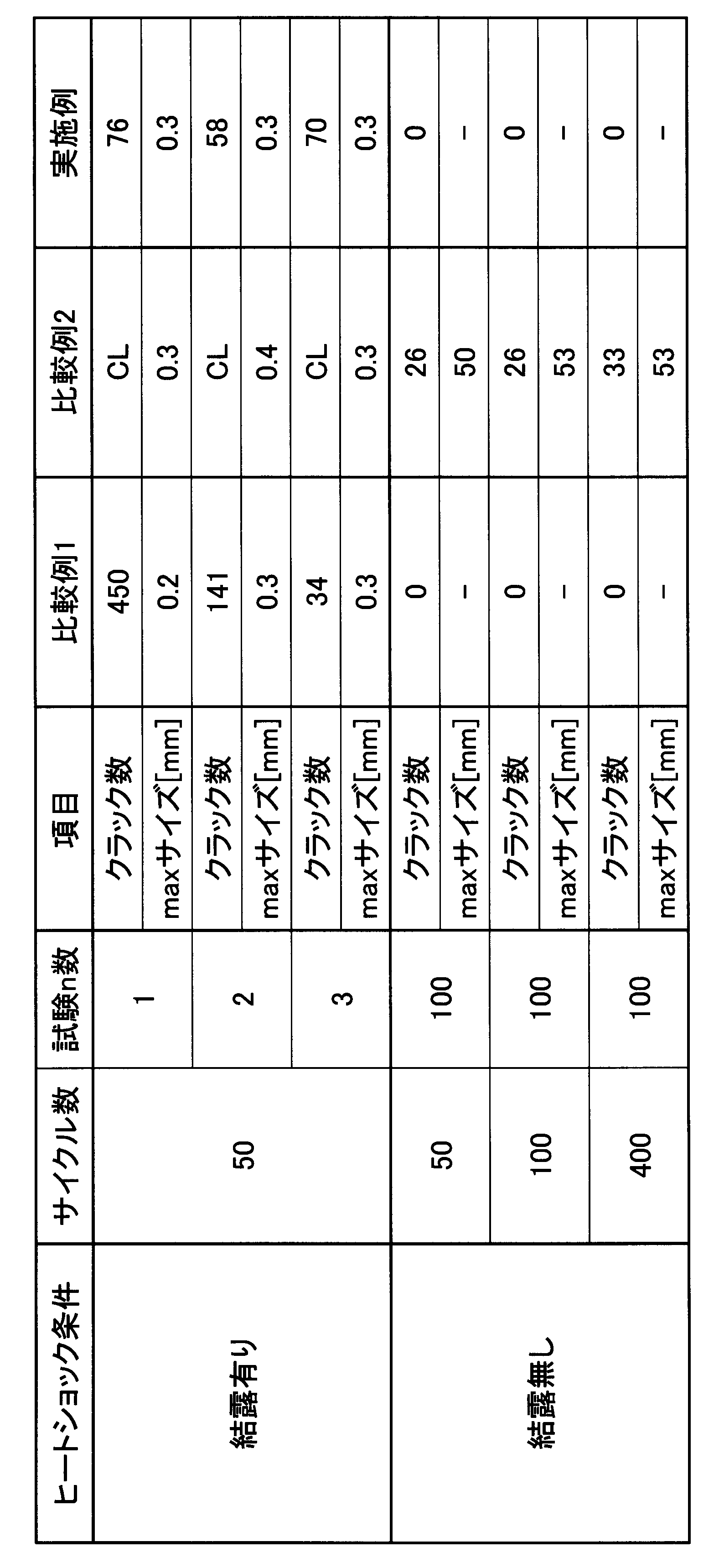
「サイクル数」は、ヒートショック試験のサイクル数である。結露有りの条件では、50サイクルの1種類とし、結露無しの条件では、50サイクル、100サイクル及び400サイクルの3種類とした。
「試験n数」は、評価枚数である。
「項目」の欄のクラック数は、光学部材の端面に観察されたクラックの数である。maxサイズ[mm]は、光学部材の端面に観察されたクラックのサイズの最大長さである。比較例及び実施例のそれぞれにおける各項目(クラック数、maxサイズ)は、全試験枚数の評価結果の平均値を示している。尚、クラック数の欄において、CLはCount Lessの略であり、クラック数が600個以上を想定している。
結露有りの条件においては、実施例の光学部材によれば、比較例1の光学部材よりも、クラック数を格段に減少することが確認された。
一方、結露無しの条件においては、実施例の光学部材と比較例1の光学部材とではクラック数が0であり、クラックが確認されなかった。また、比較例2の光学部材においては、結露無しの条件におけるものの方が結露有りの条件におけるものに比べてクラック数が格段に減少するが、クラックサイズが大きくなることが確認された。
以上の結果から、結露無しの方が結露有りよりも光学部材の端面のクラックの発生を抑制できることが分かった。また、これと反対に、結露有りの方が結露無しよりも光学部材の端面のクラックの発生を促進できることが分かった。
Claims (6)
- 偏光子と、前記偏光子の第1の面上に積層された第1の偏光子保護層と、前記偏光子の第2の面上に積層され、前記第1の偏光子保護層よりもヤング率の低い第2の偏光子保護層と、を含む光学部材の端面を切削する切削加工方法であって、
回転軸と、前記光学部材の端面側に突出する切削刃と、を有する切削部材を準備することと、
前記回転軸を中心に前記切削刃を前記第2の偏光子保護層の側から前記第1の偏光子保護層の側に回転させることと、
回転する前記切削刃を前記第2の偏光子保護層の側から侵入させて前記光学部材の端面に接触させることによって前記光学部材の端面を切削することと、
を含む切削加工方法。 - 1回の切削加工処理バッチが完了した後に切削加工後の光学部材の外形寸法を測定し、次バッチの切削加工処理によって得られる光学部材の外形寸法が要求される許容範囲以内となるように、前記次バッチの切削加工処理を始める前に、前記次バッチで切削加工処理される光学部材の端面と前記切削刃との相対位置を調整する請求項1に記載の切削加工方法。
- 前記光学部材の切削加工条件をヒートショック試験の結果に基づいて決定し、
前記ヒートショック試験では、切削加工後の光学部材にオートクレーブ処理を行い、前記光学部材を60℃~90℃で1時間加熱し、前記貼合体を常温で15分~30分放置し、前記貼合体を水温23℃~40℃で水槽に30分浸漬させる請求項1または2に記載の切削加工方法。 - 光学部材の端面を切削する切削加工装置であって、
回転軸と、前記光学部材の端面側に突出する切削刃と、を有し、前記回転軸を中心に前記切削刃を回転させ、回転する前記切削刃を前記光学部材の端面に接触させることによって前記光学部材の端面を切削する切削部材と、
前記切削部材の側方を囲むように配置されたカバーと、
前記カバーの内側部分を吸引することによって切削により生じた切屑を吸引する吸引装置と、
を含む切削加工装置。 - 前記カバーの前記切削部材を露出させる開口部の縁部に、前記切屑を付着させる飛散防止ブラシが設けられている請求項4に記載の切削加工装置。
- 前記切削部材を前記光学部材の端面に対して平行に相対移動させる移動装置をさらに含み、
前記移動装置による前記切削部材と前記光学部材との相対移動により前記光学部材の端面に前記飛散防止ブラシを接触させることによって前記光学部材の端面に付着した前記切屑を剥ぎ取るよう構成されている請求項5に記載の切削加工装置。
Priority Applications (2)
| Application Number | Priority Date | Filing Date | Title |
|---|---|---|---|
| KR1020157027683A KR102172966B1 (ko) | 2013-04-09 | 2014-04-08 | 절삭 가공 방법 |
| CN201480019774.7A CN105073318B (zh) | 2013-04-09 | 2014-04-08 | 切削加工方法以及切削加工装置 |
Applications Claiming Priority (4)
| Application Number | Priority Date | Filing Date | Title |
|---|---|---|---|
| JP2013-081215 | 2013-04-09 | ||
| JP2013081215 | 2013-04-09 | ||
| JP2013100748A JP5743291B2 (ja) | 2013-04-09 | 2013-05-10 | 切削加工方法 |
| JP2013-100748 | 2013-05-10 |
Publications (1)
| Publication Number | Publication Date |
|---|---|
| WO2014168133A1 true WO2014168133A1 (ja) | 2014-10-16 |
Family
ID=51689540
Family Applications (1)
| Application Number | Title | Priority Date | Filing Date |
|---|---|---|---|
| PCT/JP2014/060157 Ceased WO2014168133A1 (ja) | 2013-04-09 | 2014-04-08 | 切削加工方法及び切削加工装置 |
Country Status (5)
| Country | Link |
|---|---|
| JP (1) | JP5743291B2 (ja) |
| KR (1) | KR102172966B1 (ja) |
| CN (1) | CN105073318B (ja) |
| TW (1) | TWI663008B (ja) |
| WO (1) | WO2014168133A1 (ja) |
Cited By (2)
| Publication number | Priority date | Publication date | Assignee | Title |
|---|---|---|---|---|
| WO2016068243A1 (ja) * | 2014-10-31 | 2016-05-06 | 住友化学株式会社 | 偏光板の製造方法及び液晶パネルの製造方法 |
| CN107850716A (zh) * | 2015-07-16 | 2018-03-27 | 日本合成化学工业株式会社 | 聚乙烯醇系薄膜和偏光膜 |
Families Citing this family (19)
| Publication number | Priority date | Publication date | Assignee | Title |
|---|---|---|---|---|
| JP6391442B2 (ja) * | 2014-11-26 | 2018-09-19 | 住友化学株式会社 | 切削方法、切削方法を含む偏光板の製造方法、および偏光板 |
| TWI499814B (zh) * | 2015-01-30 | 2015-09-11 | Sumika Technology Co Ltd | 偏光板及其製造方法 |
| JP2016191904A (ja) * | 2015-03-30 | 2016-11-10 | 住友化学株式会社 | 偏光板 |
| TWI568524B (zh) * | 2015-06-04 | 2017-02-01 | 住華科技股份有限公司 | 端面切削刀輪 |
| KR101803675B1 (ko) * | 2016-01-19 | 2017-11-30 | 스미또모 가가꾸 가부시키가이샤 | 편광판 및 화상 표시 장치 |
| JP6188868B1 (ja) | 2016-05-26 | 2017-08-30 | 住友化学株式会社 | 偏光板、及び液晶表示装置 |
| JP6442435B2 (ja) * | 2016-05-26 | 2018-12-19 | 住友化学株式会社 | 偏光板、及び液晶表示装置 |
| JP6482522B2 (ja) * | 2016-12-22 | 2019-03-13 | 日東電工株式会社 | 端面切削加工装置及び端面切削加工方法 |
| CN106670552B (zh) * | 2016-12-28 | 2019-02-12 | 浙江速成精密机械有限公司 | 平面倒角组合铣机床 |
| JP6777315B2 (ja) * | 2017-03-31 | 2020-10-28 | 株式会社Bbs金明 | 切削加工装置 |
| KR102510750B1 (ko) * | 2017-04-04 | 2023-03-15 | 스미또모 가가꾸 가부시키가이샤 | 프로텍트 필름 부착 편광판 및 액정 패널 |
| WO2019070033A1 (ja) * | 2017-10-05 | 2019-04-11 | 住友化学株式会社 | 光学部材の製造方法及び製造装置 |
| JP6837460B2 (ja) * | 2017-10-05 | 2021-03-03 | 住友化学株式会社 | 光学部材の製造方法及び製造装置 |
| TWI844517B (zh) * | 2017-11-10 | 2024-06-11 | 日商普林科技有限公司 | 樹脂組成物、清漆、接著劑、密封劑、塗料及成形品 |
| CN108673282B (zh) * | 2018-08-04 | 2024-03-05 | 湖南谱特光电科技有限公司 | 一种偏光片生产磨边装置 |
| KR102542729B1 (ko) * | 2018-12-18 | 2023-06-12 | 주식회사 엘지화학 | 편광판 면취 장치 및 이를 이용한 편광판의 면취 방법 |
| JP6704081B1 (ja) * | 2019-07-05 | 2020-06-03 | 住友化学株式会社 | 積層体の端面を加工する方法、端面加工フィルムの製造方法、及び、端面加工装置 |
| JP7335126B2 (ja) * | 2019-10-15 | 2023-08-29 | 住友化学株式会社 | 光学部材の製造方法 |
| KR102648649B1 (ko) * | 2023-12-27 | 2024-03-18 | (주)고운스틸 | 파이프가공시스템 |
Citations (4)
| Publication number | Priority date | Publication date | Assignee | Title |
|---|---|---|---|---|
| JPS60154102U (ja) * | 1985-02-13 | 1985-10-14 | 株式会社平安鉄工所 | 木工用ルータ機の集塵装置 |
| JPH0398008U (ja) * | 1990-01-26 | 1991-10-09 | ||
| JPH09285939A (ja) * | 1996-04-22 | 1997-11-04 | Shiyouda Tekko Kk | 工作機用ヘッド部の集塵装置 |
| JP2007223021A (ja) * | 2006-01-27 | 2007-09-06 | Nitto Denko Corp | シート状部材の切削加工方法と製造方法、シート状部材、光学素子及び画像表示装置 |
Family Cites Families (4)
| Publication number | Priority date | Publication date | Assignee | Title |
|---|---|---|---|---|
| US20050158136A1 (en) * | 2004-01-15 | 2005-07-21 | Nitto Denko Corporation | Cutting method and cutting apparatus for layered sheet, layered sheet, optical element and image display |
| JP4782998B2 (ja) * | 2004-09-13 | 2011-09-28 | 住友化学株式会社 | 切削部材およびこれを備えた鏡面加工装置 |
| JP5823677B2 (ja) * | 2009-09-30 | 2015-11-25 | 住友化学株式会社 | フィルムの端面加工用カッターおよびこれを備える加工機、並びに、フィルムの端面加工方法 |
| TW201311379A (zh) * | 2011-09-08 | 2013-03-16 | Four Sun Tech Inc | 圓形塑料之鏡面及微結構切割工法 |
-
2013
- 2013-05-10 JP JP2013100748A patent/JP5743291B2/ja active Active
-
2014
- 2014-04-08 WO PCT/JP2014/060157 patent/WO2014168133A1/ja not_active Ceased
- 2014-04-08 CN CN201480019774.7A patent/CN105073318B/zh active Active
- 2014-04-08 KR KR1020157027683A patent/KR102172966B1/ko active Active
- 2014-04-09 TW TW103113061A patent/TWI663008B/zh active
Patent Citations (4)
| Publication number | Priority date | Publication date | Assignee | Title |
|---|---|---|---|---|
| JPS60154102U (ja) * | 1985-02-13 | 1985-10-14 | 株式会社平安鉄工所 | 木工用ルータ機の集塵装置 |
| JPH0398008U (ja) * | 1990-01-26 | 1991-10-09 | ||
| JPH09285939A (ja) * | 1996-04-22 | 1997-11-04 | Shiyouda Tekko Kk | 工作機用ヘッド部の集塵装置 |
| JP2007223021A (ja) * | 2006-01-27 | 2007-09-06 | Nitto Denko Corp | シート状部材の切削加工方法と製造方法、シート状部材、光学素子及び画像表示装置 |
Cited By (4)
| Publication number | Priority date | Publication date | Assignee | Title |
|---|---|---|---|---|
| WO2016068243A1 (ja) * | 2014-10-31 | 2016-05-06 | 住友化学株式会社 | 偏光板の製造方法及び液晶パネルの製造方法 |
| JP2016090691A (ja) * | 2014-10-31 | 2016-05-23 | 住友化学株式会社 | 偏光板の製造方法 |
| CN107850716A (zh) * | 2015-07-16 | 2018-03-27 | 日本合成化学工业株式会社 | 聚乙烯醇系薄膜和偏光膜 |
| CN107850716B (zh) * | 2015-07-16 | 2021-01-08 | 三菱化学株式会社 | 聚乙烯醇系薄膜和偏光膜 |
Also Published As
| Publication number | Publication date |
|---|---|
| TWI663008B (zh) | 2019-06-21 |
| JP2014217941A (ja) | 2014-11-20 |
| JP5743291B2 (ja) | 2015-07-01 |
| TW201446367A (zh) | 2014-12-16 |
| CN105073318B (zh) | 2017-05-24 |
| KR20150139520A (ko) | 2015-12-11 |
| KR102172966B1 (ko) | 2020-11-02 |
| CN105073318A (zh) | 2015-11-18 |
Similar Documents
| Publication | Publication Date | Title |
|---|---|---|
| JP5743291B2 (ja) | 切削加工方法 | |
| CN107924019A (zh) | 偏振板的制造方法及其制造装置 | |
| CN102520541B (zh) | 液晶显示元件的制造方法 | |
| CN107921555A (zh) | 偏振板的制造方法及其制造装置 | |
| TWI764679B (zh) | 偏光片、偏光板及圖像顯示裝置 | |
| TWI875694B (zh) | 經切削加工之附黏著劑層之光學積層體之製造方法 | |
| JP6188868B1 (ja) | 偏光板、及び液晶表示装置 | |
| TW201930089A (zh) | 片狀膜的製造方法 | |
| KR102259441B1 (ko) | 파단 장치 및 분단 방법 | |
| JP2012027455A (ja) | 液晶パネルの製造方法及び製造システム | |
| KR20150044369A (ko) | 탄성 지지판, 파단 장치 및 분단 방법 | |
| JP6826886B2 (ja) | 偏光板、及び、液晶パネルの製造方法 | |
| CN107526192A (zh) | 面板翻转装置以及制造光学显示元件的系统和方法 | |
| TWI842838B (zh) | 偏光板 | |
| JP2009186497A (ja) | 液晶表示パネルの製造装置および液晶表示パネルの製造方法 | |
| JP2025019281A (ja) | 光透過性積層体の検査方法および検査装置 | |
| JP6755223B2 (ja) | 偏光子、偏光板及び画像表示装置 | |
| JP2017211663A (ja) | 偏光板、及び液晶表示装置 | |
| JP4977263B2 (ja) | 液晶パネルの製造方法及び製造システム | |
| CN116234654B (zh) | 合成树脂膜的制造方法 | |
| JP5717002B2 (ja) | 切断装置 | |
| JP6204804B2 (ja) | 遊技盤の製造方法 | |
| WO2020095792A1 (ja) | 積層体、積層体の製造方法、光学体の形成方法及びカメラモジュール搭載装置 |
Legal Events
| Date | Code | Title | Description |
|---|---|---|---|
| WWE | Wipo information: entry into national phase |
Ref document number: 201480019774.7 Country of ref document: CN |
|
| 121 | Ep: the epo has been informed by wipo that ep was designated in this application |
Ref document number: 14782849 Country of ref document: EP Kind code of ref document: A1 |
|
| ENP | Entry into the national phase |
Ref document number: 20157027683 Country of ref document: KR Kind code of ref document: A |
|
| NENP | Non-entry into the national phase |
Ref country code: DE |
|
| 122 | Ep: pct application non-entry in european phase |
Ref document number: 14782849 Country of ref document: EP Kind code of ref document: A1 |