WO2014162444A1 - シース - Google Patents
シース Download PDFInfo
- Publication number
- WO2014162444A1 WO2014162444A1 PCT/JP2013/059919 JP2013059919W WO2014162444A1 WO 2014162444 A1 WO2014162444 A1 WO 2014162444A1 JP 2013059919 W JP2013059919 W JP 2013059919W WO 2014162444 A1 WO2014162444 A1 WO 2014162444A1
- Authority
- WO
- WIPO (PCT)
- Prior art keywords
- blood
- sheath
- lumen
- sheath body
- peripheral surface
- Prior art date
- Legal status (The legal status is an assumption and is not a legal conclusion. Google has not performed a legal analysis and makes no representation as to the accuracy of the status listed.)
- Ceased
Links
Images






Classifications
-
- A—HUMAN NECESSITIES
- A61—MEDICAL OR VETERINARY SCIENCE; HYGIENE
- A61M—DEVICES FOR INTRODUCING MEDIA INTO, OR ONTO, THE BODY; DEVICES FOR TRANSDUCING BODY MEDIA OR FOR TAKING MEDIA FROM THE BODY; DEVICES FOR PRODUCING OR ENDING SLEEP OR STUPOR
- A61M25/00—Catheters; Hollow probes
- A61M25/0067—Catheters; Hollow probes characterised by the distal end, e.g. tips
- A61M25/0068—Static characteristics of the catheter tip, e.g. shape, atraumatic tip, curved tip or tip structure
- A61M25/007—Side holes, e.g. their profiles or arrangements; Provisions to keep side holes unblocked
-
- A—HUMAN NECESSITIES
- A61—MEDICAL OR VETERINARY SCIENCE; HYGIENE
- A61M—DEVICES FOR INTRODUCING MEDIA INTO, OR ONTO, THE BODY; DEVICES FOR TRANSDUCING BODY MEDIA OR FOR TAKING MEDIA FROM THE BODY; DEVICES FOR PRODUCING OR ENDING SLEEP OR STUPOR
- A61M25/00—Catheters; Hollow probes
- A61M25/01—Introducing, guiding, advancing, emplacing or holding catheters
-
- A—HUMAN NECESSITIES
- A61—MEDICAL OR VETERINARY SCIENCE; HYGIENE
- A61M—DEVICES FOR INTRODUCING MEDIA INTO, OR ONTO, THE BODY; DEVICES FOR TRANSDUCING BODY MEDIA OR FOR TAKING MEDIA FROM THE BODY; DEVICES FOR PRODUCING OR ENDING SLEEP OR STUPOR
- A61M25/00—Catheters; Hollow probes
- A61M25/0021—Catheters; Hollow probes characterised by the form of the tubing
- A61M25/0023—Catheters; Hollow probes characterised by the form of the tubing by the form of the lumen, e.g. cross-section, variable diameter
-
- A—HUMAN NECESSITIES
- A61—MEDICAL OR VETERINARY SCIENCE; HYGIENE
- A61M—DEVICES FOR INTRODUCING MEDIA INTO, OR ONTO, THE BODY; DEVICES FOR TRANSDUCING BODY MEDIA OR FOR TAKING MEDIA FROM THE BODY; DEVICES FOR PRODUCING OR ENDING SLEEP OR STUPOR
- A61M25/00—Catheters; Hollow probes
- A61M25/01—Introducing, guiding, advancing, emplacing or holding catheters
- A61M25/06—Body-piercing guide needles or the like
- A61M25/0662—Guide tubes
-
- A—HUMAN NECESSITIES
- A61—MEDICAL OR VETERINARY SCIENCE; HYGIENE
- A61M—DEVICES FOR INTRODUCING MEDIA INTO, OR ONTO, THE BODY; DEVICES FOR TRANSDUCING BODY MEDIA OR FOR TAKING MEDIA FROM THE BODY; DEVICES FOR PRODUCING OR ENDING SLEEP OR STUPOR
- A61M25/00—Catheters; Hollow probes
- A61M25/01—Introducing, guiding, advancing, emplacing or holding catheters
- A61M25/09—Guide wires
-
- A—HUMAN NECESSITIES
- A61—MEDICAL OR VETERINARY SCIENCE; HYGIENE
- A61M—DEVICES FOR INTRODUCING MEDIA INTO, OR ONTO, THE BODY; DEVICES FOR TRANSDUCING BODY MEDIA OR FOR TAKING MEDIA FROM THE BODY; DEVICES FOR PRODUCING OR ENDING SLEEP OR STUPOR
- A61M25/00—Catheters; Hollow probes
- A61M25/0043—Catheters; Hollow probes characterised by structural features
- A61M25/0045—Catheters; Hollow probes characterised by structural features multi-layered, e.g. coated
- A61M2025/0046—Coatings for improving slidability
- A61M2025/0047—Coatings for improving slidability the inner layer having a higher lubricity
-
- A—HUMAN NECESSITIES
- A61—MEDICAL OR VETERINARY SCIENCE; HYGIENE
- A61M—DEVICES FOR INTRODUCING MEDIA INTO, OR ONTO, THE BODY; DEVICES FOR TRANSDUCING BODY MEDIA OR FOR TAKING MEDIA FROM THE BODY; DEVICES FOR PRODUCING OR ENDING SLEEP OR STUPOR
- A61M25/00—Catheters; Hollow probes
- A61M25/0043—Catheters; Hollow probes characterised by structural features
- A61M2025/0062—Catheters; Hollow probes characterised by structural features having features to improve the sliding of one part within another by using lubricants or surfaces with low friction
-
- A—HUMAN NECESSITIES
- A61—MEDICAL OR VETERINARY SCIENCE; HYGIENE
- A61M—DEVICES FOR INTRODUCING MEDIA INTO, OR ONTO, THE BODY; DEVICES FOR TRANSDUCING BODY MEDIA OR FOR TAKING MEDIA FROM THE BODY; DEVICES FOR PRODUCING OR ENDING SLEEP OR STUPOR
- A61M25/00—Catheters; Hollow probes
- A61M25/0067—Catheters; Hollow probes characterised by the distal end, e.g. tips
- A61M25/0068—Static characteristics of the catheter tip, e.g. shape, atraumatic tip, curved tip or tip structure
- A61M2025/0073—Tip designed for influencing the flow or the flow velocity of the fluid, e.g. inserts for twisted or vortex flow
-
- A—HUMAN NECESSITIES
- A61—MEDICAL OR VETERINARY SCIENCE; HYGIENE
- A61M—DEVICES FOR INTRODUCING MEDIA INTO, OR ONTO, THE BODY; DEVICES FOR TRANSDUCING BODY MEDIA OR FOR TAKING MEDIA FROM THE BODY; DEVICES FOR PRODUCING OR ENDING SLEEP OR STUPOR
- A61M25/00—Catheters; Hollow probes
- A61M25/01—Introducing, guiding, advancing, emplacing or holding catheters
- A61M25/06—Body-piercing guide needles or the like
- A61M25/0662—Guide tubes
- A61M2025/0681—Systems with catheter and outer tubing, e.g. sheath, sleeve or guide tube
Definitions
- the present invention relates to a sheath, and more particularly to an introducer sheath used for percutaneously introducing a catheter into a blood vessel.
- a catheter that can be inserted along a blood vessel up to the lesion is used to treat the lesion occurring in the blood vessel.
- the catheter is generally inserted to a predetermined position in the blood vessel via a lumen in the introducer sheath placed in the blood vessel, and is guided into the blood vessel from a distal end opening formed at the distal end of the introducer sheath. Then, it is inserted as it is along the blood vessel to the vicinity of the lesioned part.
- the catheter by inserting the catheter into the blood vessel through the introducer sheath, it is possible to easily secure the blood vessel and prevent friction between the catheter and the skin when the lesioned part is treated with the catheter.
- the introducer sheath has an elongated shape for insertion into a blood vessel, and a part of the inner peripheral surface of the introducer sheath comes into contact with the catheter, thereby obstructing the slidability of the catheter. there were. For this reason, there is a case where the operator cannot quickly insert the catheter into the blood vessel because the operator feels resistance during the catheter procedure. In particular, when a long introducer sheath is used, it takes a lot of time just to insert the catheter into the lesion. In view of this, a technique for improving the slidability of the catheter by coating a hydrophilic polymer that exhibits lubricity by wetting (water absorption) on the inner peripheral surface of the introducer sheath has been developed.
- the hydrophilic polymer in order for the hydrophilic polymer to exhibit lubricity, it is necessary to allow blood to flow into the lumen of the introducer sheath and to wet the hydrophilic polymer with blood.
- the distal end portion of the introducer sheath since the distal end portion of the introducer sheath has a shape that is narrowed and reduced in diameter so as to improve penetration into the living body, there is almost no gap between the distal end opening portion and the catheter, and the distal end opening portion Only a small amount of blood can flow into the lumen.
- Patent Document 1 discloses an introducer sheath in which blood in a blood vessel flows into a lumen by providing a side hole in a side wall. Thereby, the blood can be allowed to flow into the lumen without going through the tip opening of the introducer sheath.
- the side hole formed in the side wall is formed for the purpose of flowing blood into a part of the lumen in order to measure the blood pressure electrocardiogram, and blood is not distributed over a wide range in the lumen. For this reason, even if a hydrophilic polymer is coated on the inner peripheral surface of the introducer sheath, blood is not supplied to the entire hydrophilic polymer, so that the slidability of the catheter cannot be greatly improved.
- the present invention has been made to solve such a conventional problem, and an object thereof is to provide a sheath capable of circulating blood over a wide range in the lumen.
- the sheath according to the present invention includes an elongated sheath body for insertion into a blood vessel, a lumen formed in the sheath body, and at least one formed through the outer peripheral wall in the vicinity of the distal end portion of the sheath body.
- a distal side ramp and at least one proximal side ramp formed through the outer peripheral wall in the vicinity of the proximal end of the sheath body, and flows blood into the lumen along the blood flow in the blood vessel.
- at least one distal side inclined path is formed so as to be inclined toward the proximal side from the outer peripheral surface of the sheath body toward the inner peripheral surface, and at least one proximal end.
- the side inclined path is formed so as to be inclined toward the distal end side from the outer peripheral surface of the sheath body toward the inner peripheral surface.
- the inner peripheral surface of the sheath body is coated with a hydrophilic polymer which is wetted by blood flowing into the sheath body and exhibits lubricity.
- a spiral groove is preferably formed on the inner peripheral surface of the sheath body so that blood flowing into the lumen flows while drawing a spiral trajectory.
- at least one of the distal end side inclined path and the proximal end inclined path can be formed to be further inclined in the circumferential direction of the sheath body along the groove.
- the method of using the sheath according to the present invention includes placing the sheath described above in a blood vessel, introducing the catheter into the blood vessel via a lumen formed in the sheath body, and from the outer peripheral surface in the vicinity of the distal end portion of the sheath body.
- At least one distal side inclined path formed so as to incline toward the inner peripheral surface toward the proximal end side, and so as to incline toward the distal end side from the outer peripheral surface toward the inner peripheral surface in the vicinity of the proximal end portion of the sheath body.
- the at least one proximal-side ramp formed allows blood to flow into and out of the lumen along the blood flow in the blood vessel.
- blood is allowed to flow into the lumen along the blood flow in the blood vessel and the blood is allowed to flow out of the lumen, so that it is possible to circulate blood over a wide range within the lumen.
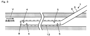
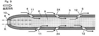
- FIG. 3 is a cross-sectional view showing a configuration of a sheath body according to Embodiment 1.
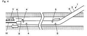
- FIG. It is a figure which shows the state by which the introducer sheath was detained in the blood vessel. It is a figure which shows a mode that the catheter was introduce
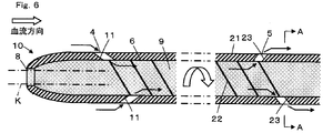
- 6 is a cross-sectional view showing a configuration of a sheath body according to Embodiment 2.
- FIG. 10 is a cross-sectional view showing a configuration of a sheath body according to a modification of the second embodiment.
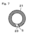
- FIG. 7 is a sectional view taken along line AA in FIG. 6. It is sectional drawing which shows a mode that the sheath main body has been arrange
- the introducer sheath is a device for securing an access route into the body cavity.
- the hand operation unit side of the device is referred to as “proximal end side”, and the side inserted into the body cavity is referred to as “distal end side”.
- FIG. 1 shows the structure of an introducer sheath provided with a sheath body according to Embodiment 1 of the present invention.
- the introducer sheath 1 is for introducing a catheter into a blood vessel, and has a sheath body 3 inserted into the blood vessel and a hub 2 disposed at the proximal end of the sheath body 3.
- the sheath body 3 has an elongated shape for insertion into a blood vessel.
- an elliptical opening 4 is formed in the vicinity of the distal end portion, and an elliptical opening 5 is formed in the vicinity of the proximal end portion. Further, as shown in FIG.
- a lumen 6 extending from the proximal end to the distal end is formed inside the sheath body 3, and the proximal end side of the lumen 6 is connected to a port 7 formed in the hub 2.
- the distal end side of the lumen 6 is connected to a distal end opening 8 formed at the distal end of the sheath body 3.
- a hemostasis valve composed of an elastic member is fixed to the hub 2 in a fluid-tight manner so that blood does not leak after the introducer sheath is placed in the blood vessel.
- the hub 2 may be provided with a side port so that a liquid such as physiological saline can be injected into the introducer sheath.
- the inner peripheral surface of the sheath body 3 is coated with a hydrophilic polymer 9 that is wetted by blood flowing into the sheath body and exhibits lubricity.
- hydrophilic polymer 9 include cellulose-based polymer materials, polyethylene oxide-based polymer materials, and maleic anhydride-based polymer materials (for example, maleic anhydride copolymers such as methyl vinyl ether-maleic anhydride copolymer). ), Acrylamide polymer materials (for example, polyacrylamide, block copolymer of polyglycidyl methacrylate-dimethylacrylamide (PGMA-DMAA)), water-soluble nylon, polyvinyl alcohol, polyvinylprolidone, and the like.
- PGMA-DMAA polyglycidyl methacrylate-dimethylacrylamide
- the distal end portion 10 of the sheath body 3 is formed so that the outer peripheral portion gradually becomes thinner toward the distal end in order to improve the piercing property when the introducer sheath 1 is inserted into the blood vessel. . Therefore, the lumen 6 of the sheath body 3 has a sufficient clearance for blood to flow between it and the catheter K, whereas the distal end opening 8 has only a slight clearance between the catheter K and the lumen 6. In other words, blood in the blood vessel hardly flows into the lumen 6 from the tip opening 8. Thus, since the inflow of the blood from the front-end
- a distal end side inclined path 11 extending from the opening 4 and penetrating the outer peripheral wall and communicating with the lumen 6 is formed in the vicinity of the distal end portion of the sheath body 3.
- a base end side inclined path 12 that extends from the opening 5, penetrates the outer peripheral wall, and communicates with the lumen 6 is formed.
- the distal end side inclined path 11 and the proximal end side inclined path 12 are formed so as to incline so that blood flows into the lumen 6 and blood flows out of the lumen 6 along the blood flow in the blood vessel.
- the distal side inclined path 11 is formed so as to be inclined toward the proximal side from the outer peripheral surface of the sheath body 3 toward the inner peripheral surface
- the proximal side inclined path 12 is formed from the outer peripheral surface of the sheath body 3 to the inner periphery. It is formed so as to incline toward the tip toward the surface.
- the sheath body 3 can be made of, for example, a metal such as a pseudoelastic alloy, a shape memory alloy and stainless steel, or a resin such as polyolefin, polyvinyl chloride and polyamide.
- the sheath body 3 can be used in various lengths depending on the application, for example, a sheath body of 10 cm to 100 cm can be used.
- the puncture needle is punctured from the skin toward the blood vessel, and the guide wire is inserted into the blood vessel through the lumen of the puncture needle.
- the puncture needle is removed from the blood vessel while the guide wire is left in the blood vessel, and a dilator equipped with an introducer sheath is inserted into the blood vessel through the skin along the guide wire.
- the guide wire and the dilator are removed from the blood vessel while the introducer sheath is placed in the blood vessel, and the introducer sheath 1 is placed in the blood vessel V as shown in FIG.
- the introducer sheath 1 is inserted until the opening 5 formed in the vicinity of the proximal end portion is located in the blood vessel V.
- the opening 5 is as downstream as possible with respect to the blood flow. Preferably it is located. That is, the opening 5 is positioned in the vicinity of the proximal end portion in the insertion portion 13 of the introducer sheath 1 inserted into the blood vessel V.
- the guide wire W and the catheter K are sequentially introduced from the port 7 formed in the hub 2.
- the distal end opening 8 of the sheath body 3 is largely open, and blood flows into the lumen 6 from the distal end opening 8.
- the hydrophilic polymer 9 coated on the inner peripheral surface of the sheath body 3 is wetted by blood and exhibits lubricity. Therefore, the catheter K introduced from the port 7 is smoothly inserted to the distal end portion of the sheath body 3. Then, as shown in FIG.
- the catheter K is led out from the distal end opening 8 of the sheath body 3 into the blood vessel V.
- the catheter K is led out from the distal end opening 8 into the blood vessel, most of the distal end opening 8 is blocked with the catheter K as shown in FIG. There is only a slight gap.
- the blood in the blood vessel V can hardly flow into the lumen 6 through the distal end opening 8, and the blood that has moved to the proximal end side from the outside of the sheath body 3 as it is is the distal end of the sheath body 3. It flows into the lumen 6 through the distal end side inclined path 11 from the opening 4 formed in the vicinity of the portion.
- the distal end side inclined path 11 is formed to be inclined toward the proximal end side from the outer peripheral surface of the sheath main body 3 toward the inner peripheral surface, the blood is smoothly flowed against the blood flow in the blood vessel V. Into the lumen 6. For this reason, it is possible to allow blood to flow into the lumen 6 from the blood vessel V without greatly reducing the blood momentum.
- the blood that has flowed into the lumen 6 from the distal side inclined path 11 is circulated along the lumen 6 toward the proximal side where the proximal side inclined path 12 is formed.
- the hydrophilic polymer 9 is coated on the inner peripheral surface of the sheath body 3, and a part of the blood flowing through the lumen 6 is supplied to the hydrophilic polymer 9.
- the hydrophilic polymer 9 is wetted with blood, and lubricity is imparted to the inner peripheral surface of the sheath body 3.
- the blood that has circulated in the lumen 6 to the vicinity of the proximal end portion of the sheath body 3 passes through the blood vessel V from the opening 5 via the proximal-side inclined path 12 formed near the proximal end portion of the sheath body 3. It is leaked in.
- the proximal-side inclined path 12 is formed so as to be inclined toward the distal end side from the outer peripheral surface of the sheath body 3 toward the inner peripheral surface. It can flow smoothly into V.
- the opening 4 near the distal end of the sheath body 3
- blood is continuously supplied to the hydrophilic polymer 9 coated on the inner peripheral surface of the sheath body 3, and the inner peripheral surface of the sheath body 3 can be maintained in a lubricated state.
- the catheter K By making the inner peripheral surface of the sheath main body 3 in a lubricated state, the catheter K has a large sliding resistance from the inner peripheral surface of the sheath main body 3 even after being led out from the distal end opening 8 of the sheath main body 3 into the blood vessel.
- the blood vessel V can be rapidly advanced along the guide wire W.
- tip part of the catheter K is delivered to the target lesioned part, and the lesioned part treatment by the catheter K is performed. Also during this treatment operation, since the catheter K does not receive a large sliding resistance, the catheter K can be moved finely, and an accurate treatment can be performed on the lesioned part.
- blood is allowed to flow in and out of the lumen 6 along with the blood flow in the blood vessel V, so that blood can be smoothly flowed in and out, Blood can be continuously circulated in the lumen 6.
- the hydrophilic polymer 9 coated on the inner peripheral surface of the sheath body 3 can be maintained in a swollen state, and the inner peripheral surface of the sheath body 3 can be maintained in a lubricated state.
- the distal end side inclined path 11 and the proximal end side inclined path 12 are formed so that blood can smoothly flow into the lumen 6 and blood can smoothly flow out of the lumen 6, a large number of the sheath body 3 can be provided. There is no need to form a through-hole, and at least one distal-side ramp 11 and at least one proximal-side ramp 12 may be formed. Thus, the strength of the sheath body 3 can be maintained by reducing the number of through holes formed in the sheath body 3. Thus, the sheath body is prevented from being kinked at the time of introduction into the skin or blood vessel, and the insertion resistance of the catheter into the introducer sheath is prevented from increasing.
- a spiral groove can be further formed on the inner peripheral surface of the sheath body 3 of the first embodiment so that blood flows in the lumen 6 while drawing a spiral trajectory.
- a spiral groove 22 extending continuously from the distal end side inclined path 11 to the proximal end side inclined path 12 can be formed on the inner peripheral surface of the sheath body 21.
- the distal end side inclined path 11 formed in the vicinity of the distal end portion of the sheath body 21 enters the lumen 6.
- the blood that has flowed in flows through the lumen 6 to the proximal end side while drawing a spiral trajectory.
- the blood circulating in the lumen 6 is moved to the outer side, that is, the radial direction of the sheath body 21 by centrifugal force while proceeding to the proximal end side.
- the blood in the lumen 6 flows to the proximal end side while spreading to the inner peripheral surface side of the sheath body 21, and the blood flows through the proximal end side inclined path 12 when the blood is circulated to the vicinity of the proximal end portion of the sheath body 21.
- the blood vessel V Through the blood vessel V.
- the blood in the lumen 6 is circulated to the proximal end side while moving to the inner peripheral surface side.
- the amount of blood outflow from the end-side ramp 12 can be further improved.
- the flow rate of blood flowing in the lumen 6 is improved.
- blood can be circulated continuously in the lumen 6, and the hydrophilicity coated on the inner peripheral surface of the sheath body 3.
- the polymer 9 can be continuously wetted to maintain lubricity.
- At least one of the distal end side inclined path 11 and the proximal end side inclined path 12 may be further inclined in the circumferential direction of the sheath body 21 along the spiral groove 22. it can.
- a proximal side inclined path 23 can be formed near the proximal end portion of the sheath body 21.
- the proximal-side inclined path 23 is formed so as to be inclined toward the distal end side from the outer peripheral surface of the sheath main body 21 toward the inner peripheral surface, and to be inclined in the circumferential direction of the sheath main body 21 along the groove 22.
- the base end side inclined path 23 is inclined in the radial direction and the circumferential direction of the sheath body 21, and is formed on the extension line of the groove 22.
- the blood circulated in the lumen 6 while drawing a spiral trajectory from the distal end side to the proximal end side in the trajectory. Accordingly, the blood can flow out from the lumen 6 into the blood vessel V, and the blood can flow out from the lumen 6 more smoothly.
- the flexibility of the sheath body is also improved, and the sheath body portion of the introducer sheath becomes a blood vessel at the time of blood vessel introduction. It becomes easy to bend along.
- the introducer sheath is inserted into the blood vessel V so that the distal end side is upstream with respect to the blood flow direction in the blood vessel V, but the distal end side is downstream. Even when inserted into the blood vessel V, the same effect can be obtained.
- FIG. 8 shows an example in which the introducer sheath 1 of Embodiment 1 is inserted into the blood vessel V so that the distal end side is downstream with respect to the blood flow direction in the blood vessel V. In this way, blood in the blood vessel V smoothly flows into the lumen 6 from the opening 5 formed in the vicinity of the proximal end portion of the sheath body 3 through the proximal-side inclined path 12, and the proximal end is passed through the lumen 6.
- the blood circulated from the side to the tip side smoothly flows out from the opening 4 into the blood vessel V through the tip side inclined path 11 formed in the vicinity of the tip portion of the sheath body 3. That is, when the introducer sheath 1 is arranged so that the distal end side is downstream, only the blood flow direction in the lumen 6 is reversed, and there is no need to change the structure. In this manner, blood is allowed to flow into and out of the lumen along the blood flow in the blood vessel V, so that blood can be smoothly flowed in and out.
- the distal side inclined path is formed in the vicinity of the distal end portion of the sheath body.
- the distal end side inclined path extends over a wide range from the vicinity of the proximal end portion of the sheath body to the vicinity of the central portion. It can also be formed.
- the base-side ramp is formed in the vicinity of the base end portion of the sheath body.
- the base-side ramp is changed from the vicinity of the base end portion of the sheath body to the vicinity of the central portion. It can also be formed over a wide range. For example, as shown in FIG.
- the base end side inclined path that inclines toward the base end side from the outer peripheral surface toward the inner peripheral surface. 24 can be further formed.
- the openings 4 and 5 are formed in an oval shape.
- the blood flows into the lumen along the blood flow in the blood vessel V and the blood flows out from the lumen.
- the present invention is not limited to this.
- a circular opening 25 can be formed in the sheath body 3.
- a crescent-shaped opening 26 can be formed in the sheath body 3.
- a square opening or a rectangular opening may be formed in the sheath body.
- the introducer sheath is used as the sheath according to the present invention.
- any sheath may be used as long as it is inserted into the blood vessel V and blood flows into the lumen. It is not something that can be done.
- the guiding catheter it is possible to form a distal side slope near the distal end and also form a proximal side slope near the proximal end.
- blood can be circulated continuously in the guiding catheter.
- a hydrophilic polymer the slidability of the catheter or dilator inserted therein can be improved. it can.
Landscapes
- Health & Medical Sciences (AREA)
- Life Sciences & Earth Sciences (AREA)
- Biophysics (AREA)
- Pulmonology (AREA)
- Engineering & Computer Science (AREA)
- Anesthesiology (AREA)
- Biomedical Technology (AREA)
- Heart & Thoracic Surgery (AREA)
- Hematology (AREA)
- Animal Behavior & Ethology (AREA)
- General Health & Medical Sciences (AREA)
- Public Health (AREA)
- Veterinary Medicine (AREA)
- Media Introduction/Drainage Providing Device (AREA)
Abstract
Description
そこで、湿潤(吸水)により潤滑性が発揮される親水性ポリマーをイントロデューサシースの内周面にコーティングして、カテーテルの摺動性を向上させる技術が開発されている。ここで、親水性ポリマーが潤滑性を発揮するためにはイントロデューサシースのルーメン内に血液を流入させて親水性ポリマーを血液で湿潤させる必要がある。しかしながら、イントロデューサシースの先端部は、生体内への刺入性が向上するように細く縮径された形状を有するため、先端開口部とカテーテルとの間にはほとんど隙間がなく、先端開口部からルーメン内には僅かな血液しか流入することができない。このため、イントロデューサシースの内周面に親水性ポリマーをコーティングしても、親水性ポリマーに十分な血液を供給することができないため、イントロデューサシースの内周面の潤滑性が向上せず、カテーテルの摺動性を改善できないのが現状である。
また、シース本体の内周面には、ルーメン内に流入した血液がらせん状の軌道を描きながら流通するように、らせん状の溝が形成されるのが好ましい。また、先端側傾斜路および基端傾斜路の少なくとも一方は、溝に沿ってシース本体の周方向にさらに傾斜して形成することもできる。
図1に、この発明の実施の形態1に係るシース本体を備えたイントロデューサシースの構成を示す。このイントロデューサシース1は、血管内にカテーテルを導入するためのもので、血管内に挿入されるシース本体3と、シース本体3の基端に配置されたハブ2とを有する。
シース本体3は、血管内に挿入するために細長く延びた形状を有する。このシース本体3の外周面には、先端部近傍に楕円状の開口部4が形成されると共に基端部付近に楕円状の開口部5が形成されている。また、シース本体3の内部には、図2に示すように、基端から先端まで延びるルーメン6が形成されており、このルーメン6の基端側がハブ2に形成されたポート7に接続され、ルーメン6の先端側がシース本体3の先端に形成された先端開口部8に接続されている。これにより、ハブ2のポート7から導入したカテーテルKを、ルーメン6を介して先端開口部8から外部に導出することができる。また、ハブ2には、弾性部材から構成された止血弁が液密に固定されており、血管内にイントロデューサシースを留置した後、血液が漏れないように構成されている。なお、例えば、ハブ2には、イントロデューサシース内に生理食塩水等の液体を注入できるように、サイドポートを設けてもよい。
まず、穿刺針を皮膚から血管に向かって穿刺し、ガイドワイヤを穿刺針の内腔を介して血管内に挿入する。次に、ガイドワイヤを血管内に留置したまま穿刺針を血管内から抜去し、イントロデューサシースを装着したダイレータをガイドワイヤに沿わせて皮膚を介して血管内に挿入する。そして、イントロデューサシースを血管内に留置したままガイドワイヤおよびダイレータを血管内から抜去し、図3に示すように、イントロデューサシース1が血管V内に留置される。この時、イントロデューサシース1は、基端部付近に形成された開口部5が血管V内に位置するまで挿入される。ここで、血管V内の血液は、イントロデューサシース1の先端側から基端側に向かって流れているものとすると、開口部5は、血流に対して可能な限り下流側となるように位置されるのが好ましい。すなわち、開口部5は、血管V内に挿入されたイントロデューサシース1の挿入部分13において基端部近傍に位置されることになる。
カテーテルKが先端開口部8から血管内に導出されると、図2に示すように、先端開口部8の大部分がカテーテルKで塞がれ、先端開口部8とカテーテルKとの間にはわずかな隙間しかない状態となる。このため、血管V内の血液は、先端開口部8を介してルーメン6内にほとんど流入することができず、そのままシース本体3の外側を基端側に移動した血液は、シース本体3の先端部近傍に形成された開口部4から先端側傾斜路11を通ってルーメン6内に流入される。このとき、先端側傾斜路11は、シース本体3の外周面から内周面に向かって基端側に傾斜して形成されているため、血管V内の血流に逆らわずに、血液をスムーズにルーメン6内に流入させる。このため、血液の勢いを大きく低下させることなく、血管V内からルーメン6内に血液を流入させることができる。
このようにして、ルーメン6内をシース本体3の基端部付近まで流通した血液は、シース本体3の基端部付近に形成された基端側傾斜路12を介して開口部5から血管V内に流出される。この時、基端側傾斜路12は、シース本体3の外周面から内周面に向かって先端側に傾斜して形成されているため、ルーメン6内の血流に逆らわずに、血液を血管V内にスムーズに流出させることができる。
また、先端側傾斜路11と基端側傾斜路12は、ルーメン6内に血液をスムーズに流入させると共にルーメン6内から血液をスムーズに流出させるように形成されているため、シース本体3に数多くの貫通孔を形成する必要がなく、少なくとも1つの先端側傾斜路11と少なくとも1つの基端側傾斜路12を形成すればよい。このように、シース本体3に形成する貫通孔を少なくすることで、シース本体3の強度を保つことができる。それにより、皮膚又は血管への導入時などにシース本体がキンクするのを防止して、イントロデューサシース内へのカテーテルの挿入抵抗が増加するのを防止する。
実施の形態1のシース本体3の内周面には、血液がルーメン6内をらせん状の軌道を描きながら流通するように、らせん状の溝をさらに形成することができる。
例えば、図5に示すように、シース本体21の内周面に、先端側傾斜路11から基端側傾斜路12まで連続して延びるらせん状の溝22を形成することができる。このように、先端側傾斜路11と基端側傾斜路12の間に溝22を形成することにより、シース本体21の先端部近傍に形成された先端側傾斜路11を介してルーメン6内に流入された血液が、ルーメン6内をらせん状の軌道を描きながら基端側に流通される。このため、ルーメン6内を流通する血液は、基端側に進行しつつ、遠心力により外側、すなわちシース本体21の径方向にも移動される。これにより、ルーメン6内の血液は、シース本体21の内周面側に広がりながら基端側に流通し、血液がシース本体21の基端部付近まで流通されたところで基端側傾斜路12を介して血管V内に流出される。
例えば、図6および7に示すように、シース本体21の基端部付近に基端側傾斜路23を形成することができる。この基端側傾斜路23は、シース本体21の外周面から内周面に向かって先端側に傾斜すると共に溝22に沿ってシース本体21の周方向に傾斜するように形成されている。すなわち、基端側傾斜路23は、シース本体21の径方向と周方向にそれぞれ傾斜されており、溝22の延長線上に形成されることになる。
このように、基端側傾斜路23をらせん状の溝22に沿って形成することにより、ルーメン6内を先端側から基端側にらせん状の軌道を描きながら流通した血液を、その軌道に沿って基端側傾斜路23から血管V内に流出させることができ、ルーメン6内から血液をさらにスムーズに流出させることができる。
図8に、実施の形態1のイントロデューサシース1を血管V内の血流方向に対して先端側が下流となるように血管V内に挿入した一例を示す。このように、シース本体3の基端部付近に形成された開口部5から基端側傾斜路12を介して血管V内の血液がルーメン6内にスムーズに流入され、ルーメン6内を基端側から先端側に流通した血液が、シース本体3の先端部近傍に形成された先端側傾斜路11を介して開口部4から血管V内にスムーズに流出される。すなわち、イントロデューサシース1を先端側が下流となるように配置した場合には、ルーメン6内の血液の流通方向が逆になるだけで、その構造を変える必要はない。
このように、血管V内の血流に沿って、ルーメン内に血液を流入させると共にルーメン内から血液を流出させるため、血液の流入と流出をスムーズに行うことができる。
Claims (4)
- 血管内に挿入するために細長く延びたシース本体と、
前記シース本体内に形成されたルーメンと、
前記シース本体の先端部近傍に外周壁を貫通して形成された少なくとも1つの先端側傾斜路と、
前記シース本体の基端部付近に外周壁を貫通して形成された少なくとも1つの基端側傾斜路と
を備え、
血管内の血流に沿って、前記ルーメン内に血液を流入させると共に前記ルーメン内から血液を流出させるために、前記少なくとも1つの先端側傾斜路は前記シース本体の外周面から内周面に向かって基端側に傾斜するように形成されると共に、前記少なくとも1つの基端側傾斜路は前記シース本体の外周面から内周面に向かって先端側に傾斜するように形成されることを特徴とするシース。 - 前記シース本体の内周面は、シース本体内に流入した血液により、湿潤して潤滑性を発揮する親水性ポリマーでコーティングされている請求項1に記載のシース。
- 前記シース本体の内周面には、ルーメン内に流入した血液がらせん状の軌道を描きながら流通するように、らせん状の溝が形成されている請求項1または2に記載のシース。
- 前記先端側傾斜路および前記基端傾斜路の少なくとも一方は、前記溝に沿って前記シース本体の周方向にさらに傾斜して形成される請求項3に記載のシース。
Priority Applications (4)
| Application Number | Priority Date | Filing Date | Title |
|---|---|---|---|
| PCT/JP2013/059919 WO2014162444A1 (ja) | 2013-04-01 | 2013-04-01 | シース |
| JP2015509697A JP6001163B2 (ja) | 2013-04-01 | 2013-04-01 | シース |
| CN201380075280.6A CN105073176B (zh) | 2013-04-01 | 2013-04-01 | 鞘 |
| US14/868,832 US20160015934A1 (en) | 2013-04-01 | 2015-09-29 | Sheath |
Applications Claiming Priority (1)
| Application Number | Priority Date | Filing Date | Title |
|---|---|---|---|
| PCT/JP2013/059919 WO2014162444A1 (ja) | 2013-04-01 | 2013-04-01 | シース |
Related Child Applications (1)
| Application Number | Title | Priority Date | Filing Date |
|---|---|---|---|
| US14/868,832 Continuation US20160015934A1 (en) | 2013-04-01 | 2015-09-29 | Sheath |
Publications (1)
| Publication Number | Publication Date |
|---|---|
| WO2014162444A1 true WO2014162444A1 (ja) | 2014-10-09 |
Family
ID=51657777
Family Applications (1)
| Application Number | Title | Priority Date | Filing Date |
|---|---|---|---|
| PCT/JP2013/059919 Ceased WO2014162444A1 (ja) | 2013-04-01 | 2013-04-01 | シース |
Country Status (4)
| Country | Link |
|---|---|
| US (1) | US20160015934A1 (ja) |
| JP (1) | JP6001163B2 (ja) |
| CN (1) | CN105073176B (ja) |
| WO (1) | WO2014162444A1 (ja) |
Cited By (1)
| Publication number | Priority date | Publication date | Assignee | Title |
|---|---|---|---|---|
| WO2021153088A1 (ja) * | 2020-01-29 | 2021-08-05 | テルモ株式会社 | カテーテルシステム、バルーンカテーテル及び医療機器 |
Families Citing this family (3)
| Publication number | Priority date | Publication date | Assignee | Title |
|---|---|---|---|---|
| CA3036822A1 (en) | 2016-09-16 | 2018-03-22 | Surmodics, Inc. | Lubricious insertion tools for medical devices and methods for using |
| CN108814697A (zh) * | 2018-06-08 | 2018-11-16 | 罗政强 | 一种具有三维定位功能的股骨髓内钉开口器 |
| CN121016048A (zh) * | 2025-10-30 | 2025-11-28 | 苏州鼎科医疗技术股份有限公司 | 一种延长导管 |
Citations (7)
| Publication number | Priority date | Publication date | Assignee | Title |
|---|---|---|---|---|
| JPH02131402U (ja) * | 1989-04-04 | 1990-11-01 | ||
| JPH0356404U (ja) * | 1989-10-09 | 1991-05-30 | ||
| US5318535A (en) * | 1993-06-21 | 1994-06-07 | Baxter International Inc. | Low-profile dual-lumen perfusion balloon catheter with axially movable inner guide sheath |
| JPH07323090A (ja) * | 1994-05-31 | 1995-12-12 | Terumo Corp | 医療用チューブ |
| JPH11501545A (ja) * | 1995-03-07 | 1999-02-09 | マイクロ インターベンショナル システムズ,インコーポレーテッド | 親水性の遠位端を有するフローディレクテッドカテーテル |
| JP2001129074A (ja) * | 1999-11-08 | 2001-05-15 | Asahi Intecc Co Ltd | 潤滑性ガイディングカテーテルおよびスプリングガイドワイヤ |
| JP2001518819A (ja) * | 1997-04-09 | 2001-10-16 | ボストン サイエンティフィック リミテッド | 異なる可撓性の3領域を備えるカテーテル、および、その製造方法 |
Family Cites Families (20)
| Publication number | Priority date | Publication date | Assignee | Title |
|---|---|---|---|---|
| US4784638A (en) * | 1987-09-17 | 1988-11-15 | Neurodynamics, Inc. | Angled hole ventricular catheter and method of making same |
| US5037403A (en) * | 1989-11-08 | 1991-08-06 | Cordis Corporation | Pigtail catheter with angled apertures |
| US5106368A (en) * | 1990-04-20 | 1992-04-21 | Cook Incorporated | Collapsible lumen catheter for extracorporeal treatment |
| US5536250A (en) * | 1994-04-01 | 1996-07-16 | Localmed, Inc. | Perfusion shunt device and method |
| US5403291A (en) * | 1993-08-02 | 1995-04-04 | Quinton Instrument Company | Catheter with elongated side holes |
| US5395316A (en) * | 1993-08-11 | 1995-03-07 | Med-Pro Design, Inc. | Triple lumen catheter |
| US5542925A (en) * | 1993-11-05 | 1996-08-06 | Advanced Cardiovascular Systems, Inc. | Dilatation catheter with oblong perfusion ports |
| US7087039B1 (en) * | 1994-03-02 | 2006-08-08 | Scimed Life Systems, Inc. | Perfusion balloon angioplasty catheter |
| US5643228A (en) * | 1995-11-13 | 1997-07-01 | Uresil Corporation | Catheter |
| GB9828696D0 (en) * | 1998-12-29 | 1999-02-17 | Houston J G | Blood-flow tubing |
| US6514284B1 (en) * | 2000-04-20 | 2003-02-04 | Advanced Cardiovascular Systems, Inc. | Stent having inner flow channels |
| GB2371346B (en) * | 2000-12-14 | 2002-12-04 | Tayside Flow Technologies Ltd | Improving fluid flow in tubing |
| JP4409179B2 (ja) * | 2003-01-22 | 2010-02-03 | ニプロ株式会社 | 吸引性とクロス性の改良された血栓吸引カテーテル |
| EP2292183B1 (en) * | 2003-03-18 | 2017-10-25 | Veryan Medical Limited | Helical balloon with stent |
| US20050182352A1 (en) * | 2004-02-12 | 2005-08-18 | Dimatteo Kristian | Dialysis catheter tip |
| US20060240253A1 (en) * | 2005-04-22 | 2006-10-26 | Cardiac Pacemakers, Inc. | Guidewire and tube with lubricious coating |
| US8092415B2 (en) * | 2007-11-01 | 2012-01-10 | C. R. Bard, Inc. | Catheter assembly including triple lumen tip |
| US9399112B2 (en) * | 2008-04-22 | 2016-07-26 | Becton, Dickinson And Company | Catheter hole having an inclined trailing edge |
| CN201441725U (zh) * | 2009-06-08 | 2010-04-28 | 厉国 | 穿刺引流装置 |
| US8747343B2 (en) * | 2011-09-30 | 2014-06-10 | Covidien Lp | Hemodialysis catheter with improved side opening design |
-
2013
- 2013-04-01 JP JP2015509697A patent/JP6001163B2/ja active Active
- 2013-04-01 CN CN201380075280.6A patent/CN105073176B/zh not_active Expired - Fee Related
- 2013-04-01 WO PCT/JP2013/059919 patent/WO2014162444A1/ja not_active Ceased
-
2015
- 2015-09-29 US US14/868,832 patent/US20160015934A1/en not_active Abandoned
Patent Citations (7)
| Publication number | Priority date | Publication date | Assignee | Title |
|---|---|---|---|---|
| JPH02131402U (ja) * | 1989-04-04 | 1990-11-01 | ||
| JPH0356404U (ja) * | 1989-10-09 | 1991-05-30 | ||
| US5318535A (en) * | 1993-06-21 | 1994-06-07 | Baxter International Inc. | Low-profile dual-lumen perfusion balloon catheter with axially movable inner guide sheath |
| JPH07323090A (ja) * | 1994-05-31 | 1995-12-12 | Terumo Corp | 医療用チューブ |
| JPH11501545A (ja) * | 1995-03-07 | 1999-02-09 | マイクロ インターベンショナル システムズ,インコーポレーテッド | 親水性の遠位端を有するフローディレクテッドカテーテル |
| JP2001518819A (ja) * | 1997-04-09 | 2001-10-16 | ボストン サイエンティフィック リミテッド | 異なる可撓性の3領域を備えるカテーテル、および、その製造方法 |
| JP2001129074A (ja) * | 1999-11-08 | 2001-05-15 | Asahi Intecc Co Ltd | 潤滑性ガイディングカテーテルおよびスプリングガイドワイヤ |
Cited By (2)
| Publication number | Priority date | Publication date | Assignee | Title |
|---|---|---|---|---|
| WO2021153088A1 (ja) * | 2020-01-29 | 2021-08-05 | テルモ株式会社 | カテーテルシステム、バルーンカテーテル及び医療機器 |
| JPWO2021153088A1 (ja) * | 2020-01-29 | 2021-08-05 |
Also Published As
| Publication number | Publication date |
|---|---|
| CN105073176A (zh) | 2015-11-18 |
| JPWO2014162444A1 (ja) | 2017-02-16 |
| JP6001163B2 (ja) | 2016-10-05 |
| CN105073176B (zh) | 2017-11-24 |
| US20160015934A1 (en) | 2016-01-21 |
Similar Documents
| Publication | Publication Date | Title |
|---|---|---|
| JP6746503B2 (ja) | ガイドワイヤ | |
| US20070213671A1 (en) | Infusion catheter system with telescoping cannula | |
| JP2006340868A (ja) | 血管カテーテル | |
| JP2018523541A5 (ja) | ||
| US8574218B2 (en) | Catheter, fluid conveying method, and percutaneous procedure | |
| JP6001163B2 (ja) | シース | |
| JPWO2006090637A1 (ja) | 穿刺具 | |
| KR20200118090A (ko) | 천자 시스템 | |
| US20200030001A1 (en) | Intravascular memory metal puncture system and use thereof | |
| RU2712089C2 (ru) | Медицинское устройство, набор для лечения и способ лечения нарушенных кровеносных сосудов, полостей организма и протоков организма, а также способ размещения медицинского текучего вещества в окружающей их ткани | |
| US8480636B2 (en) | Catheter with aspiration passageway | |
| JP4526608B2 (ja) | イントロデューサシース | |
| JP2005058464A (ja) | カテーテル | |
| JP5111767B2 (ja) | トリプルルーメンカテーテル | |
| JP5936093B2 (ja) | ダブルルーメンダイレータ | |
| JP5112466B2 (ja) | カテーテルシステム | |
| JP2016150170A (ja) | イントロデューサシースおよびイントロデューサシースセット | |
| EP4182000A1 (en) | Integrated catheter-placement devices and methods for mitigating blood egress | |
| JP4945174B2 (ja) | 4ルーメンカテーテル | |
| JP2016022192A (ja) | カテーテル | |
| JP6233430B2 (ja) | ダブルルーメンダイレータ | |
| JP4832011B2 (ja) | トリプルルーメンカテーテル | |
| JP4264367B2 (ja) | 穿刺具 | |
| JP4316252B2 (ja) | カテーテル | |
| JP7374686B2 (ja) | カテーテル組立体 |
Legal Events
| Date | Code | Title | Description |
|---|---|---|---|
| WWE | Wipo information: entry into national phase |
Ref document number: 201380075280.6 Country of ref document: CN |
|
| 121 | Ep: the epo has been informed by wipo that ep was designated in this application |
Ref document number: 13881344 Country of ref document: EP Kind code of ref document: A1 |
|
| ENP | Entry into the national phase |
Ref document number: 2015509697 Country of ref document: JP Kind code of ref document: A |
|
| NENP | Non-entry into the national phase |
Ref country code: DE |
|
| 122 | Ep: pct application non-entry in european phase |
Ref document number: 13881344 Country of ref document: EP Kind code of ref document: A1 |