WO2014155582A1 - 船尾管シール装置 - Google Patents
船尾管シール装置 Download PDFInfo
- Publication number
- WO2014155582A1 WO2014155582A1 PCT/JP2013/059097 JP2013059097W WO2014155582A1 WO 2014155582 A1 WO2014155582 A1 WO 2014155582A1 JP 2013059097 W JP2013059097 W JP 2013059097W WO 2014155582 A1 WO2014155582 A1 WO 2014155582A1
- Authority
- WO
- WIPO (PCT)
- Prior art keywords
- seal ring
- liner
- stern
- lubricating oil
- housing
- Prior art date
Links
Images


Classifications
-
- B—PERFORMING OPERATIONS; TRANSPORTING
- B63—SHIPS OR OTHER WATERBORNE VESSELS; RELATED EQUIPMENT
- B63H—MARINE PROPULSION OR STEERING
- B63H23/00—Transmitting power from propulsion power plant to propulsive elements
- B63H23/32—Other parts
- B63H23/36—Shaft tubes
-
- B—PERFORMING OPERATIONS; TRANSPORTING
- B63—SHIPS OR OTHER WATERBORNE VESSELS; RELATED EQUIPMENT
- B63H—MARINE PROPULSION OR STEERING
- B63H23/00—Transmitting power from propulsion power plant to propulsive elements
- B63H23/32—Other parts
- B63H23/321—Bearings or seals specially adapted for propeller shafts
-
- F—MECHANICAL ENGINEERING; LIGHTING; HEATING; WEAPONS; BLASTING
- F16—ENGINEERING ELEMENTS AND UNITS; GENERAL MEASURES FOR PRODUCING AND MAINTAINING EFFECTIVE FUNCTIONING OF MACHINES OR INSTALLATIONS; THERMAL INSULATION IN GENERAL
- F16J—PISTONS; CYLINDERS; SEALINGS
- F16J15/00—Sealings
- F16J15/002—Sealings comprising at least two sealings in succession
- F16J15/006—Sealings comprising at least two sealings in succession with division of the pressure
-
- F—MECHANICAL ENGINEERING; LIGHTING; HEATING; WEAPONS; BLASTING
- F16—ENGINEERING ELEMENTS AND UNITS; GENERAL MEASURES FOR PRODUCING AND MAINTAINING EFFECTIVE FUNCTIONING OF MACHINES OR INSTALLATIONS; THERMAL INSULATION IN GENERAL
- F16J—PISTONS; CYLINDERS; SEALINGS
- F16J15/00—Sealings
- F16J15/16—Sealings between relatively-moving surfaces
- F16J15/162—Special parts or details relating to lubrication or cooling of the sealing itself
-
- F—MECHANICAL ENGINEERING; LIGHTING; HEATING; WEAPONS; BLASTING
- F16—ENGINEERING ELEMENTS AND UNITS; GENERAL MEASURES FOR PRODUCING AND MAINTAINING EFFECTIVE FUNCTIONING OF MACHINES OR INSTALLATIONS; THERMAL INSULATION IN GENERAL
- F16J—PISTONS; CYLINDERS; SEALINGS
- F16J15/00—Sealings
- F16J15/16—Sealings between relatively-moving surfaces
- F16J15/32—Sealings between relatively-moving surfaces with elastic sealings, e.g. O-rings
- F16J15/324—Arrangements for lubrication or cooling of the sealing itself
-
- F—MECHANICAL ENGINEERING; LIGHTING; HEATING; WEAPONS; BLASTING
- F16—ENGINEERING ELEMENTS AND UNITS; GENERAL MEASURES FOR PRODUCING AND MAINTAINING EFFECTIVE FUNCTIONING OF MACHINES OR INSTALLATIONS; THERMAL INSULATION IN GENERAL
- F16J—PISTONS; CYLINDERS; SEALINGS
- F16J15/00—Sealings
- F16J15/16—Sealings between relatively-moving surfaces
- F16J15/32—Sealings between relatively-moving surfaces with elastic sealings, e.g. O-rings
- F16J15/3244—Sealings between relatively-moving surfaces with elastic sealings, e.g. O-rings with hydrodynamic pumping action
-
- B—PERFORMING OPERATIONS; TRANSPORTING
- B63—SHIPS OR OTHER WATERBORNE VESSELS; RELATED EQUIPMENT
- B63H—MARINE PROPULSION OR STEERING
- B63H23/00—Transmitting power from propulsion power plant to propulsive elements
- B63H23/32—Other parts
- B63H23/321—Bearings or seals specially adapted for propeller shafts
- B63H2023/327—Sealings specially adapted for propeller shafts or stern tubes
Definitions
- the present invention uses a marine vessel propulsion shaft that passes through a housing provided on the outside of a stern tube and a seal ring that prevents seawater from entering the inside of the vessel.
- the present invention relates to a stern tube sealing device.
- seal rings made of rubber or elastomer have been used in stern tube sealing devices.
- lip-type seal rings 04, 05 which are made of an elastic member slidably contacted with a liner 03 attached to a propulsion shaft (propeller shaft) 02 that penetrates the stern tube 01.
- the first seal ring 04 disposed on the stern side and the second seal ring 05 adjacent to the first seal ring 04 are disposed so as to be sandwiched between the plurality of housing members 07, and a first stern annular space 08 is formed.
- the stern tube seal device 010 prevents the inundation of seawater, intrusion of foreign matter, and leakage of lubricating oil inside the ship by forming a second stern annular space 09 by the second seal ring 05 and the third seal ring 06. Is disclosed.
- the cross-sectional shape of the first seal ring 04 disclosed in Patent Document 1 is such that the seawater in the first stern annular space 08 is formed on the sliding contact surface where the seal ring 04 contacts the liner 03 when the propeller shaft 02 rotates.
- fine irregularities are provided so as to forcibly send out the high-pressure side out of the ship, and the sending action is positively generated when the propeller shaft 02 rotates.
- the frictional heat generated by the rotation of the propeller shaft 02 partially exceeds 150 ° C. at the sliding contact portion where the seal ring 04 contacts the liner 03. It has been.
- NBR Nirile Butadiene Rubber
- fluorine rubber or the like having high heat resistance
- the present invention has been made in view of the above-described problems, and is a stern tube that cools and lubricates the sliding contact portion of the first seal ring with the liner to prevent wear and improve the durability of the seal ring.
- An object is to provide a sealing device.
- the present invention is a stern tube sealing device constituted by a plurality of seal rings that are in contact with an outer peripheral surface of a liner of a propeller shaft that rotatably supports a propeller mounted on a stern of a ship, A housing that externally fits the liner and holds the plurality of seal rings; A first seal ring disposed on the most stern side of the plurality of seal rings; A second seal ring disposed on the ship front side of the first seal ring with a distance from the first seal ring; A nozzle that ejects lubricating oil that cools the first seal ring,
- the stern tube sealing device can be provided in which the nozzle for ejecting the lubricating oil of the nozzle is disposed in the vicinity of the sliding contact portion between the liner and the first seal ring.
- the first seal ring is effectively cooled by the lubricating oil sprayed from the jet outlet by the frictional heat generated by sliding at the peripheral contact portion between the first seal ring and the liner.
- a spiral groove is formed on a surface of the housing facing the liner and in the vicinity of the jet outlet in a direction in which the lubricating oil is pushed out toward the stern annular space with the forward rotation of the liner. It is good to provide.
- the lubricating oil is extruded to the stern annular space side, and the circumferential contact portion between the first seal ring and the liner is cooled.
- the cooling effect can be improved by making the lubricating oil to be easily ejected from the ejection port.
- the nozzle is formed in the housing.
- the nozzle in the housing, it is possible to accurately inject the lubricating oil onto the circumferential contact portion between the first seal ring and the liner, and the cooling effect can be improved.
- the nozzle is disposed in the first seal ring.
- the internal heat storage can be cooled, and the cooling efficiency of the first seal ring is further improved.
- the nozzle has a gap portion where the introduction port opens into a lubricating oil passage in the housing, and the lubricating oil passage communicating with the jet port faces the housing and the liner. It is good to be formed with the cylindrical member arrange
- the cylindrical nozzle is arranged in the gap between the housing and the liner, the nozzle arrangement structure is simplified, the manufacturing cost is reduced, and the product accuracy associated with the simplified structure is achieved. Can be improved, and can be accurately sprayed onto the sliding contact portion of the first seal ring, so that the sliding contact portion can be efficiently cooled.
- a radial portion of the liner is formed between the propeller shaft, a space portion formed by the liner fitted to the propeller shaft, the first seal ring, and the jet port.
- the lubricating oil that has cooled the sliding contact portion may be returned to the stern annular space through the space portion.
- the lubricating oil that has cooled the sliding contact portion is returned to the stern annular space through the space portion between the liner and the propeller shaft, so that the lubricating oil pressure between the injection port and the sliding contact portion is high.
- the introduction port for the lubricating oil ejected from the ejection port is open at a right angle to the lubricating oil flow direction of the lubricating oil passage in the housing.
- the lubricating oil can easily enter the nozzle. Therefore, the amount of lubricating oil ejected from the ejection port increases, and the cooling efficiency of the first seal ring is improved.
- a stern tube sealing device that improves the durability of the seal ring by intensively cooling the sliding contact portion of the first seal ring with the liner with the lubricating oil ejected from the nozzle. it can.
- FIG. 1 shows a schematic cross-sectional view of a stern tube sealing device in which the present invention is implemented.
- the principal part expanded sectional view of 1st Embodiment of this invention is shown.
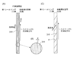
- (A) is a development view in the circumferential direction of a thread groove provided on the surface of the housing facing the liner of FIG. 2
- (B) is a partial enlarged view of (A)
- (C) is a development view of another shape. Show.
- the principal part expanded sectional view of 2nd Embodiment of this invention is shown.
- the principal part expanded sectional view of 3rd Embodiment of this invention is shown.
- the principal part expanded sectional view of 4th Embodiment of this invention is shown. It is explanatory drawing of a prior art.
- the stern tube sealing device 12 is provided with a propeller shaft 10 for propulsion of a ship having a propeller 21 attached to the end thereof and a stern tube 15 protruding from the stern tube 15 to the outside of the stern (stern side).
- a housing 13 through which the shaft 10 passes, and seal rings 1, 2, and 3 that seal between the inner peripheral surface of the housing 13 and the outer peripheral side of the liner 11 fitted on the propeller shaft 10 are configured.
- the liner 11 of the propeller shaft 10 is fixed to the propeller 21 by bolts 11a.
- the body portion of the liner 11 surrounds the outer periphery of the propeller shaft 10 and rotates integrally with the propeller shaft 10.
- a lip-shaped first seal ring 1, second seal ring 2, and third seal ring 3 are in sliding contact with the outer periphery of the trunk portion of the liner 11 from the stern side.
- a fishing net prevention ring 14 is attached on the furthermost stern side of the first seal ring 1. The fishing net prevention ring 14 prevents foreign matter in seawater such as a fishing net from entering the stern tube sealing device 12.
- the housing 13 is integrally fixed to the stern tube 15 by bolts 13f, with a plurality of housings 13a to 13e overlapping in a stacked state in the axial direction of the propeller shaft 10.
- the plurality of housings 13a to 13e are arranged in order of the first housing 13a, the second housing 13b, the third housing 13c, the fourth housing 13d, and the fifth housing 13e from the stern side.
- Each of the first, second and third seal rings is fixed in a state of being sandwiched between the housings 13a to 13e.
- the lips of the first seal ring 1 and the second seal ring 2 are directed to the seawater side, and the third seal ring 3 is directed to the bow side.
- seal rings 1, 2, 3 and 18 are made of rubber or elastomer elastic members, and the rubber material is made of fluoro rubber or NBR having excellent water resistance, oil resistance and heat resistance.
- the seal ring has an annular shape, and the cross-sectional shape of the ring portion has a constant cross-sectional shape, and the body portion of the liner 11 is inserted into the hollow portion at the center.
- the first seal ring 1 and the second seal ring 2 form a first stern annular space 4 that is a stern annular space
- the second seal ring 2 and the third seal ring 3 form a second stern annular space 5.
- a stern tube chamber 19 communicating with an oil reservoir tank 27 is formed in the stern tube 15 between the third seal ring 3 and the fourth seal ring 18.
- Lubricating oil is always supplied to the first stern annular space 4 via an oil feed pipe 7 connected to an oil reservoir tank 6 for storing lubricating oil provided in the ship.
- the oil sump tank 6 is adjusted so that the hydraulic pressure in the first stern annular space 4 is lower than the axial draft pressure.
- the oil reservoir tank 6 is provided with a replenishment line 28 for replenishing the lubricating oil and a valve 29 for adjusting the lubrication oil replenishment when the lubricating oil in the oil reservoir tank 6 decreases.
- the second stern annular space 5 includes an air vent line 8 that communicates with the atmosphere, and a drain that collects the stern tube bearing lubricating oil (the lubricating oil in the first stern annular space 4 and the stern tube chamber 19) in the event of leakage.
- Line 9 is connected.
- 48 is a drain tank. Since the second stern annular space 5 is open to the atmosphere, the pressure in the stern tube chamber can be independently set lower than the axial draft pressure, so that the pressure in the stern tube chamber 19 can be reduced, and the load on the fourth seal ring 18 is reduced. The durability of the fourth seal ring 18 can be improved.
- the lubricating oil flows through the oil feeding pipe 7 in the stern pipe 15 and the oil passages drilled in the fifth, fourth, and third housings 13e, 13d, and 13c, and the first stern annular space is formed in the third housing 13c. 4 is supplied.
- the lubricating oil flowing through the oil feed pipe 7 and each oil passage is adjusted so that a pressure lower than the axial core draft pressure acts. This is to reduce the load on the first seal ring 1 when the propeller shaft 10 rotates.
- FIG. 2 shows a partially enlarged view of the housing 13 in the present embodiment.
- Each oil passage is drilled in the wall portion of the stern tube 15, and is connected to the first oil passage 7a connected to the oil feeding tube 7, and the second oil passage opened at a position facing the first oil passage 7a of the fifth housing 13e. 7b, a third oil passage 7c opened at a position facing the second oil passage 7b of the fourth housing 13d, and a fourth oil passage 7d opened at a position opposed to the third oil passage 7c of the third housing 13c. It consists of
- the third housing 13c has an inlet 31c that opens to the fourth oil passage 7d and takes in lubricating oil, and extends radially inward in the radial direction continuously to the inlet 31c.
- Axial which is provided with a lubricant outlet 31d in the vicinity of the sliding contact portion G with the liner 11 of the first seal ring 1 and is bent toward the first seal ring 1 side, continuously from the path 31a and the radial oil path 31a.
- a nozzle 31 having a directional oil passage 31b is provided.
- the radial oil passage 31a and the axial oil passage 31b function as a nozzle that injects lubricating oil onto the sliding contact portion G that is in sliding contact with the liner 11 of the first seal ring 1.
- the inlet 31c is opened in a direction perpendicular to the flow of the lubricating oil that flows linearly from the third oil passage 7c to the fourth oil passage 7d. Therefore, the inlet 31c is arranged so that the lubricating oil can easily enter the nozzle 31 by the fluid pressure of the lubricant acting on the inlet 31c.
- the nozzles 31 are provided at a plurality of locations in a ring shape along the outer peripheral surface of the liner 11.
- FIG. 3A is a developed view in the circumferential direction of the inner peripheral surface 31e of FIG. 2A (the surface facing the liner 11 of the housing 13).
- the lubricating oil is moved to the first stern annular space 4 side through a gap R between the housing 13 and the liner 11.
- a spiral groove 31f having a pumping action is formed.
- the spiral groove 31f is formed in a direction in which the lubricating oil is rotated along with the rotation of the liner and pushed toward the first stern annular space 4 when the liner 11 rotates in the forward direction (rotates in the direction in which the ship moves forward).
- the lubricating oil flows along the spiral groove 31f in the direction of ⁇ in FIG.
- a pumping action is exerted on the inner peripheral surface 31e of the housing 13 in the direction in which the lubricating oil is pushed out toward the first stern annular space 4 side. Therefore, the lubricating oil that cools the sliding contact portion G between the first seal ring 1 and the liner 11 is easily ejected from the ejection port 31d, and the cooling effect of the sliding contact portion G can be improved by more lubricating oil. it can.
- the spiral groove 31f is a single spiral groove and has a structure in which the pumping action is slightly suppressed.
- the twist angle ⁇ (lead angle) of the spiral groove 31f is suppressed to 1 to 10 degrees. This is because the amount of the lubricating oil ejected from the ejection port 31d is suppressed by suppressing the twist angle ⁇ to 1 to 10 degrees. If the lubricating oil is ejected more than necessary from the ejection port 31d, the load on the lubricating hydraulic pump increases, leading to an output of the internal combustion engine and fuel consumption loss.
- the suppression of the pumping action prevents the lubricating oil pressure at the sliding contact portion G from being lowered.
- the twist angle ⁇ (lead angle) of the spiral groove 31f is increased as shown in FIG. It is also possible to increase the efficiency.
- Lubricating oil in the oil sump tank 6 flows through the oil feed pipe 7 and each oil passage, and is ejected from the ejection port 31 d of the nozzle 31 toward the sliding contact portion G with the liner 11 of the first seal ring 1.
- the lubricating oil that has cooled the sliding contact portion G with the liner 11 of the first seal ring 1 circulates in the first stern annular space 4, passes through an oil passage and a lubricating oil cooling device (not shown), and reaches an oil reservoir tank.
- the third housing 13c has a shape in which the first stern annular space 4 side of the third housing 13c is expanded in the axial direction and the radial direction in order to provide the nozzle 31 in the third housing 13c.
- the part where the nozzle 31 is not disposed has an action as a backup ring when the pressure acts on the first seal ring 1 from the seawater side, and improves the effect of the part as the seal ring. Can do. Further, since the nozzle 31 for injecting the lubricating oil is disposed in the third housing 13c, the lubricating oil is accurately injected to the sliding contact portion G with the liner 11 of the first seal ring 1, so that the first seal The cooling efficiency of the ring 1 can be improved.
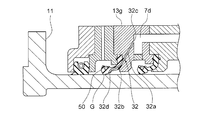
- the present embodiment is the same as the first embodiment except that the nozzle arrangement structure is different. Therefore, the description other than the nozzle forming portion is omitted. Further, the same parts are denoted by the same reference numerals and description thereof is omitted.
- the first seal ring 50 is fixed by the second housing 13b and the third housing 13g.
- the third housing 13g has an inlet 32c that opens into the fourth oil passage 7d and takes in the lubricant, and a first nozzle 32a that forms a lubricant passage drilled to the portion of the first seal ring 50. Is arranged.
- the first seal ring 50 is internally communicated with the lubricating oil passage of the first nozzle 32a, and is opened in the vicinity of the sliding contact portion G that is in sliding contact with the liner 11 of the first seal ring 50.
- a second nozzle 32b having a jet port 32d for injecting oil is formed.
- the first nozzle 32 a and the second nozzle 32 b function as a nozzle 32 that injects lubricating oil to the sliding contact portion G that is in sliding contact with the liner 11 of the first seal ring 50.
- the nozzles 32 composed of the first nozzles 32 a and the second nozzles 32 b are arranged in a plurality of locations in a ring shape along the outer peripheral surface of the liner 11.
- the lubricating oil is accurately applied to the sliding contact portion G of the first seal ring 50 from the first nozzle 32a through the second nozzle 32b formed inside the first seal ring 50. Is injected into. Furthermore, since the lubricating oil passes through the inside of the first seal ring 50, it is possible to easily cool the inside where heat is easily stored, and the first seal ring 50 can be cooled more effectively. One seal ring 50 can be effectively cured and prevented from being worn.
- the present embodiment is the same as the first embodiment except that the nozzle arrangement structure is different. Therefore, the description other than the nozzle forming portion is omitted. Further, the same parts are denoted by the same reference numerals and description thereof is omitted.
- a nozzle 33 is fixed to the third housing 13h at the downstream end of the fourth oil passage 7d.
- the nozzle 33 opens the lubricating oil intake port 33c at the downstream end of the fourth oil passage 7d, and extends in the first stern annular space 4 radially inward in the radial direction center portion 33a.
- the gap portion R between the housing 13h and the liner 11 is bent toward the first seal ring 1, and an outlet 33d for discharging the lubricating oil is opened in the vicinity of the slidable contact portion G that is in sliding contact with the liner 11 of the first seal ring 1. It is formed with the extended axial direction part 33b.
- a notch S in which the axially extending portion 33 b of the nozzle 33 is fitted is disposed in the axial direction.
- the notch S is formed in a semicircular cross section in a direction perpendicular to the axial direction.
- the lubricating oil flows from the downstream end of the fourth oil passage 7d through the radial extending portion 33a and the axial extending portion 33b of the nozzle 33, and from the jet port 33d to the first outlet. Sprayed in the vicinity of the sliding contact portion G that is in sliding contact with the liner 11 of the seal ring 1, the first seal ring 1 can be cooled more effectively, and the first seal ring 1 is effectively cured and prevented from wearing. Can be implemented.
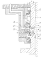
- the present embodiment is the same as the third embodiment except that the lubricating oil that has cooled the sliding contact portion G is returned to the stern annular space by utilizing the space portion V between the liner 11 portion and the propeller shaft 10. . Therefore, the description is omitted except that the lubricating oil that has cooled the sliding contact portion G is returned to the stern annular space. Further, the same parts are denoted by the same reference numerals and description thereof is omitted.
- the nozzle 33 opens the lubricating oil intake port 33 c at the downstream end of the fourth oil passage 7 d, and the inside of the first stern annular space 4 that is the stern annular space is radial.
- a radial direction extending portion 33a extending toward the center in the direction and a gap portion R between the third housing 13h and the liner 11 are bent toward the first seal ring 1 side, and a jet outlet 33d that discharges lubricating oil is provided in the first
- the seal ring 1 is formed by an axially extending portion 33 b opened near the sliding contact portion G that is in sliding contact with the liner 11.
- the liner 11 is externally fitted to the propeller shaft 10 and is fixed to the propeller shaft 10.
- the inner peripheral surfaces of the annular stern-side projection 11f and the bow-side projection 11g projecting toward the propeller shaft 10 and the outer peripheral surface of the propeller shaft 10 are fitted to both ends in the axial direction of the inner peripheral surface of the liner 11. Yes.
- the space portion V between the stern side projection 11 f and the bow side projection 11 g of the liner 11 is an annular space sealed by the outer peripheral surface of the propeller shaft 10.
- first return oil passage 11a communicating with the space V in the radial direction of the liner 11 and the first stern annular space 4 at an intermediate position between the first seal ring 1 of the liner 11 and the jet outlet 33d of the nozzle 33.
- second return oil passage 11b communicating with the space V in the radial direction of the liner 11 and the stern side position of the first return oil passage 11a.
- the propeller shaft 10 protrudes from the liner 11 to the propeller shaft 10 side at the bow side position of the first annular protrusion 11c and the second return oil passage 11b, which protrudes toward the propeller shaft 10 and is fitted on the outer peripheral surface of the propeller shaft 10. And a second annular protrusion 11d that is externally fitted to the outer peripheral surface. And the 3rd oil path 11e formed in a part of space part V used as the cyclic
- the lubricating oil that has cooled the sliding contact portion G passes through the third return oil passage 11e between the liner 11 and the propeller shaft 10 from the plurality of first return oil passages 11a, and then from the plurality of second return oil passages 11d. It flows near the bow side position of the nozzle 33 in the first stern annular space 4.
- the lubricating oil pressure between the injection port 33d and the sliding contact portion G is prevented from becoming too high, and it is easy to ensure the amount of the lubricating oil ejected from the ejection port 33d.
- the heat inside the liner 11 heat from the sliding contact portion
Abstract
Description
例えば、特許文献1には、図7に示すように、船尾管01を貫通する推進軸(プロペラ軸)02に取付けられたライナー03に摺接する弾性部材からなるリップ型のシールリング04,05,06が複数のハウジング部材に07に挟まるように配設され、船尾側に配設した第1シールリング04と、これに隣接する第2シールリング05によって第1船尾環状空間08を形成すると共に、第2シールリング05と第3シールリング06とによって第2船尾環状空間09を形成するようにして、海水の浸水や異物の侵入、及び船内側の潤滑油の漏洩を防止する船尾管シール装置010が開示されている。
ところが、船舶の大型化、高速化に伴って、シールリング04がライナー03と接触する摺接部は、プロペラ軸02の回転により発生する摩擦熱が部分的には150℃以上になることが知られている。[船尾管シール装置用シールリング材の研究(第1報)]
そのため、シールリングの材料として耐熱性の高い、NBR(Nitrile Butadiene Rubber)、フッ素ゴム等が使用されている。
このような状況下においても、シールリングのライナーとの摺接部は摩耗が進み、定期的にシールリングの交換が必要となっている。
交換のため、高価な船舶の稼働を停止し、大きな部材(プロペラ、推進軸等)の取外し、取付け等により、船舶の稼働率の低下と大きな交換費用が生じている。
前記ライナーを外嵌し、前記複数のシールリングを保持しているハウジングと、
前記複数のシールリングの最船尾側に配設された第1シールリングと、
前記第1シールリングの前記船舶前側に前記第1シールリングと間隔を有して配設された第2シールリングと、
前記第1シールリングを冷却する潤滑油を噴出するノズルと、を備え、
前記ノズルの前記潤滑油を噴出する噴出口を、前記ライナーと前記第1シールリングとの摺接部近傍に配設したことを特徴とする船尾管シール装置を提供できる。
これにより、周接部における第1シールリングの摩耗及び硬化が抑制でき、第1シールリングの耐久性が向上し、第1シールリングの交換時期が延長され船舶のランニングコストの抑制が図れる。
前記摺接部を冷却した潤滑油が前記空間部を介して前記船尾環状空間に戻るようにするとよい。
従って、噴出口から噴出される潤滑油量が多くなり、第1シールリングの冷却効率が向上する。
但し、この実施形態に記載されている構成部品の寸法、材質、形状、その相対配置などは特に特定的な記載がない限り、この発明の範囲をそれのみに限定する趣旨ではなく、単なる説明例にすぎない。
図1を参照して、船尾管シール装置12の全体構成について説明する。
船尾管シール装置12は、図1に示すようにプロペラ21が端部に取付けられた船舶推進用のプロペラ軸10と、船尾管15から船外側(船尾側)に突出して設けられ、内部にプロペラ軸10が貫通するハウジング13と、該ハウジング13の内周面とプロペラ軸10に外嵌したライナー11の外周側との間をシールするシールリング1,2,3によって構成されている。
プロペラ21にはボルト11aによってプロペラ軸10のライナー11が固定されている。
ライナー11の胴部はプロペラ軸10の外周を囲いプロペラ軸10と一体に回転するようになっている。
このライナー11の胴部外周には、最船尾側からリップ形の第1シールリング1、第2シールリング2及び第3シールリング3が摺接している。
また、第1シールリング1の更に最船尾側には、漁網防止リング14が取付けられている。漁網防止リング14は、漁網等の海水中の異物が船尾管シール装置12内に入り込むのを防止している。
複数のハウジング13a~13eは、船尾側から、第1ハウジング13a、第2ハウジング13b、第3ハウジング13c、第4ハウジング13d、及び第5ハウジング13eの順に配設されている。
第1、第2および第3シールリング夫々は、ハウジング13a~13eに挟み込まれた状態で固定されている。
そして、第1シールリング1及び第2シールリング2のリップは海水側に向けられ、第3シールリング3は船首側に向けられている。
これら、シールリング1,2,3及び18は、ゴム又はエラストマーの弾性部材からなり、ゴム材料としては、耐水、耐油、耐熱性に優れたフッ素ゴム又はNBRによって形成されている。
また、シールリングは円環形状を成し、リング部分の断面形状は一定断面形状を有し、中心の中空部分にライナー11の胴部が挿入されるようになっている。
第3シールリング3と第4シールリング18との間の船尾管15内には、油溜りタンク27に連通する船尾管室19が形成されている。
油溜りタンク6は、第1船尾環状空間4の液圧が軸芯喫水圧よりも低くなるように調整されている。
油溜りタンク6には、該油溜りタンク6内の潤滑油が低下すると、潤滑油を補給するための補給ライン28と、潤滑油補給の調整を行うバルブ29が付設されている。
第2船尾環状空間5には、大気に連通する空気抜きライン8と、船尾管軸受潤滑油(第1船尾環状空間4及び船尾管室19の潤滑油)の漏れ発生の場合にこれを回収するドレンライン9が接続されている。48はドレンタンクである。
第2船尾環状空間5は大気解放なので、船尾管室の圧力を独自に軸芯喫水圧より低く設定できるので、船尾管室19の圧力を低くでき、第4シールリング18の負荷が下げられ、第4シールリング18の耐久性を向上させることができる。
既述の通り、送油管7及び各油路内を流通する潤滑油は、軸芯喫水圧より低い圧力が作用するように調整されている。
これは、プロペラ軸10の回転時における第1シールリング1の負荷を軽減するためである。
図2に本実施形態における、ハウジング13の部分拡大図を示す。
各油路は、船尾管15の壁部に穿設され、送油管7が連結した第1油路7aと、第5ハウジング13eの第1油路7aと対向した位置に開口した第2油路7bと、第4ハウジング13dの第2油路7bと対向した位置に開口した第3油路7cと、第3ハウジング13cの第3油路7cに対向した位置に開口した第4油路7dとで構成されている。
ラジアル方向油路31aとアキシャル方向油路31bとによって、第1シールリング1のライナー11と摺接する摺接部Gに潤滑油を噴射するノズルとしての機能を有している。
導入口31cは、第3油路7cから第4油路7dにかけて直線的に流れる潤滑油の流れに対し、直角方向に開口されている。
従って、導入口31cは、潤滑油の流動圧が導入口31cに作用して、ノズル31内に潤滑油が多く入り易いように配設してある。
そして、ノズル31は、ライナー11の外周面に沿って環状に複数個所に配設けられている。
ハウジング13の潤滑油の噴出口31d近傍で、且つライナー11と対向した内周面31eには、ハウジング13とライナー11との隙間部Rを介して、潤滑油を第1船尾環状空間4側へ押出すポンプ作用を有した螺旋溝31fが形成されている。
螺旋溝31fは、ライナー11が正回転(船舶が前進する方向に回転)時に、潤滑油がライナーの回転に連れまわりして、第1船尾環状空間4側へ押出す方向に形成されている。
従って、潤滑油は、螺旋溝31fに沿って図3(A)の⇒の方向に流れる。
ハウジング13の内周面31eに潤滑油を第1船尾環状空間4側へ押出す方向にポンピング作用を発揮させている。
従って、第1シールリング1とライナー11との摺接部Gを冷却する潤滑油は、噴出口31dから噴出し易くなり、より多くの潤滑油によって摺接部Gの冷却効果を向上させることができる。
本実施形態では、図3(B)に図3(A)の部分拡大図を示すように、螺旋溝31fの捩り角α(リード角)を1~10度に抑えてある。
捩り角αを1~10度に抑えることにより、噴出口31dからの潤滑油噴出量を抑制するためである。
潤滑油を噴出口31dから必要以上に噴出させると、潤滑油圧送ポンプの負荷が大きくなり内燃機関の出力及び燃費ロスをまねく。
また、ポンピング作用の抑制は、摺接部Gの潤滑油圧力が低下するのを防止したものである。
尚、噴出口31dからの潤滑油の噴出量が多い場合には、必要に応じて、図3(C)に示すように、螺旋溝31fの捩り角θ(リード角)を大きくして、ポンピング効率を大きくすることも可能である。
第1シールリング1のライナー11との摺接部Gを冷却した潤滑油は、第1船尾環状空間4内を循環して、図示されない油路及び潤滑油冷却装置を通過して、油溜りタンク6に戻る。
これにより、摺接部における第1シールリング1の摩耗及び硬化が抑制でき、第1シールリング1の耐久性が向上し、第1シールリング1の交換時期が延長され船舶のランニングコストの抑制が図れる。
また、第3ハウジング13cは、該第3ハウジング13cにノズル31を設けるため、第3ハウジング13cの第1船尾環状空間4側をアキシャル方向及びラジアル方向に膨出させた形状にしてある。
更に潤滑油を噴射するノズル31を、第3ハウジング13cに配設しているので、潤滑油が第1シールリング1のライナー11との摺接部Gに的確に噴射されるので、第1シールリング1の冷却効率を向上させることができる。
本実施形態は、第1実施形態に対し、ノズルの配置構造が異なる以外は同じなので、ノズル形成部以外の説明は省略する。
更に、同一部品については同一の符号を付して、説明を省略する。
第3ハウジング13gには、第4油路7dに開口して潤滑油を取入れる導入口32cを有し、第1シールリング50の部分まで穿設された潤滑油通路を形成する第1ノズル32aが配設されている。
そして、第1ノズル32aと第2ノズル32bとによって、第1シールリング50のライナー11と摺接する摺接部Gに潤滑油を噴射するノズル32としての機能を有している。
第1ノズル32aと第2ノズル32bとで構成されたノズル32は、ライナー11の外周面に沿って環状に複数個所に配設されている。
更に、潤滑油は、第1シールリング50の内部を通過するため、蓄熱され易い内部も容易に冷却することが可能となり、第1シールリング50の冷却を更に効果的に行うことができ、第1シールリング50の熱硬化及び摩耗の防止を効果的に実施できる。
本実施形態は、第1実施形態に対し、ノズルの配置構造が異なる以外は同じなので、ノズル形成部以外の説明は省略する。
更に、同一部品については同一の符号を付して、説明を省略する。
ノズル33は、潤滑油の取入口33cを第4油路7dの下流側端部に開口し、第1船尾環状空間4内をラジアル方向中心側に延在したラジアル方向延在部33aと、第3ハウジング13hとライナー11との隙間部Rを第1シールリング1側に屈曲させ、潤滑油を排出する噴出口33dを、第1シールリング1のライナー11と摺接する摺接部G近傍に開口させたアキシャル方向延在部33bとで形成されている。
また、第3ハウジング13hのライナー11に対向する面には、ノズル33のアキシャル方向延在部33bが嵌入する切欠部Sがアキシャル方向に配設されている。
切欠部Sは、アキシャル方向に対する直角方向断面が半円状に形成されている。
本実施形態は、ライナー11部とプロペラ軸10との空間部Vを利用して、摺接部Gを冷却した潤滑油を船尾環状空間に戻すようにした以外は第3実施形態と同じである。
従って、摺接部Gを冷却した潤滑油を船尾環状空間に戻すようにした以外は、説明を省略する。
更に、同一部品については同一の符号を付して、説明を省略する。
ライナー11内周面の軸線方向両端部には、プロペラ軸10側に突出した環状の船尾側突起部11f及び船首側突起11gの内周面と、プロペラ軸10の外周面とが嵌合している。
そして、ライナー11の船尾側突起部11fと船首側突起11gとの間の空間部Vは、プロペラ軸10の外周面によって密閉された環状の空間になっている。
そして、第1環状突起11cと、第2環状突起11dとで形成された環状の戻し油路となる空間部Vの一部に形成された第3油路11eが形成されている。
尚、第1戻し油路11aと、第2戻し油路11bはライナー11の周方向に間隔を有して、複数配設されている。
このような構造にすることにより、噴射口33dと摺接部G間の潤滑油圧力が高くなりすぎるのを防止して、潤滑油の噴出口33dからの噴出量を確保し易くすると共に、第1戻し油路11aを通る潤滑油によって、ライナー11内部の熱(摺接部による熱)を冷却することができる。
2 第2シールリング
3 第3シールリング
4 第1船尾環状空間(船尾環状空間)
5 第2船尾環状空間
6 油溜りタンク
7 送油管
7a 第1油路
7b 第2油路
7c 第3油路
7d 第4油路
10 プロペラ軸
11 ライナー
11a 第1戻し油路
11b 第2戻し油路
11e 第3戻し油路
12 船尾管シール装置
13 ハウジング
13a 第1ハウジング
13b 第2ハウジング
13c、13g、13h 第3ハウジング
13d 第4ハウジング
13e 第5ハウジング
15 船尾管
18 第4シールリング
31,32,33 ノズル
G 摺接部
R 隙間部
S 切欠部
V 空間部
Claims (7)
- 船舶の船尾に装着されるプロペラを回転可能に支持するプロペラ軸のライナーの外周面に周接する複数のシールリングによって構成された船尾管シール装置であって、
前記ライナーを外嵌し、前記複数のシールリングを保持しているハウジングと、
前記複数のシールリングの最船尾側に配設された第1シールリングと、
前記第1シールリングの前記船舶前側に前記第1シールリングと間隔を有して配設された第2シールリングと、
前記第1シールリングを冷却する潤滑油を噴出するノズルと、を備え、
前記ノズルの前記潤滑油を噴出する噴出口を、前記ライナーと前記第1シールリングとの摺接部近傍に配設したことを特徴とする船尾管シール装置。 - 前記ハウジングの前記ライナーと対向した面で且つ、前記噴出口近傍に、前記ライナーの正転に伴い前記潤滑油を前記船尾環状空間側へ押出す方向に螺旋溝を設けたことを特徴とする請求項1記載の船尾管シール装置。
- 前記ノズルは前記ハウジングに形成されていることを特徴とする請求項1又は2のいずれかに記載の船尾管シール装置。
- 前記ノズルは、前記第1シールリング内に配設されていることを特徴とする請求項1乃至3のいずれかに記載の船尾管シール装置。
- 前記ノズルは、前記導入口が前記ハウジング内の潤滑油路内に開口し、前記噴出口に連通する潤滑油路が、前記ハウジングと前記ライナーとが対向した隙間部に配設された筒状部材で形成されていることを特徴とする請求項1又は2のいずれかに記載の船尾管シール装置。
- 前記プロペラ軸と、前記プロペラ軸に外嵌する前記ライナーとで形成する空間部と、前記第1シールリングと、前記噴出口との間に前記ライナーのラジアル方向に前記空間部に連通する第1戻し油路と、前記ライナーの前記船尾環状空間と対向する部分に前記ライナーのラジアル方向に前記空間部と前記船尾環状空間とを連通する第2戻し油路とを備え、
前記摺接部を冷却した潤滑油が前記空間部を介して前記船尾環状空間に戻るようにしたことを特徴とする請求項1乃至5のいずれかに記載の船尾管シール装置。 - 前記噴出口から噴出する潤滑油の導入口は、前記ハウジング内の潤滑油路の潤滑油流通方向に対し直角方に開口していることを特徴とする請求項1乃至5のいずれかに記載の船尾管シール装置。
Priority Applications (5)
| Application Number | Priority Date | Filing Date | Title |
|---|---|---|---|
| PCT/JP2013/059097 WO2014155582A1 (ja) | 2013-03-27 | 2013-03-27 | 船尾管シール装置 |
| KR1020157026555A KR101745234B1 (ko) | 2013-03-27 | 2013-03-27 | 선미관 시일 장치 |
| JP2015507784A JP6126203B2 (ja) | 2013-03-27 | 2013-03-27 | 船尾管シール装置 |
| CN201380074038.7A CN105189285B (zh) | 2013-03-27 | 2013-03-27 | 船尾管密封装置 |
| EP13880388.7A EP2979973B1 (en) | 2013-03-27 | 2013-03-27 | Stern pipe seal device |
Applications Claiming Priority (1)
| Application Number | Priority Date | Filing Date | Title |
|---|---|---|---|
| PCT/JP2013/059097 WO2014155582A1 (ja) | 2013-03-27 | 2013-03-27 | 船尾管シール装置 |
Publications (1)
| Publication Number | Publication Date |
|---|---|
| WO2014155582A1 true WO2014155582A1 (ja) | 2014-10-02 |
Family
ID=51622659
Family Applications (1)
| Application Number | Title | Priority Date | Filing Date |
|---|---|---|---|
| PCT/JP2013/059097 WO2014155582A1 (ja) | 2013-03-27 | 2013-03-27 | 船尾管シール装置 |
Country Status (5)
| Country | Link |
|---|---|
| EP (1) | EP2979973B1 (ja) |
| JP (1) | JP6126203B2 (ja) |
| KR (1) | KR101745234B1 (ja) |
| CN (1) | CN105189285B (ja) |
| WO (1) | WO2014155582A1 (ja) |
Cited By (3)
| Publication number | Priority date | Publication date | Assignee | Title |
|---|---|---|---|---|
| CN104828237A (zh) * | 2015-04-23 | 2015-08-12 | 广州科技职业技术学院 | 船舶尾管结构 |
| JP2019065728A (ja) * | 2017-09-29 | 2019-04-25 | 北越工業株式会社 | 油冷式スクリュ圧縮機 |
| CN113247226A (zh) * | 2021-05-11 | 2021-08-13 | 中交广州航道局有限公司 | 一种防艉轴封漏油漏水装置及其使用方法 |
Families Citing this family (7)
| Publication number | Priority date | Publication date | Assignee | Title |
|---|---|---|---|---|
| WO2017122358A1 (ja) * | 2016-01-15 | 2017-07-20 | バルチラジャパン株式会社 | 船尾管シールシステム、船尾管シール装置、船舶、及び船尾管シール方法 |
| CN105782452B (zh) * | 2016-03-31 | 2017-12-29 | 武汉船用机械有限责任公司 | 一种用于吊舱推进器的艉轴密封结构 |
| CN108825789A (zh) * | 2018-09-06 | 2018-11-16 | 兰州理工大学 | 高速机械密封冷却冲洗装置 |
| EP3854674B1 (en) * | 2018-11-20 | 2022-05-18 | Wartsila Japan Ltd. | Draught meter and vessel |
| KR101995781B1 (ko) | 2018-11-23 | 2019-07-03 | (주)한국알앤드디 | 소형 선박 추진기용 부유물 유입방지장치 |
| CN111120658B (zh) * | 2020-01-03 | 2022-04-05 | 湖南永盛船舶有限公司 | 一种可调式船用艉轴密封装置 |
| CN111810641B (zh) * | 2020-06-04 | 2023-03-31 | 江门市鑫辉密封科技有限公司 | 一种密封圈及密封装置 |
Citations (5)
| Publication number | Priority date | Publication date | Assignee | Title |
|---|---|---|---|---|
| JPH026384B2 (ja) * | 1981-02-20 | 1990-02-08 | Blohm Voss Ag | |
| JPH055341Y2 (ja) * | 1987-11-30 | 1993-02-12 | ||
| JP2909948B2 (ja) * | 1993-05-10 | 1999-06-23 | 三菱重工業株式会社 | 船尾管軸封装置 |
| JP2000238694A (ja) | 1999-02-23 | 2000-09-05 | Nippon Marine Techno Kk | 船尾管シール装置 |
| WO2008099648A1 (ja) * | 2007-02-16 | 2008-08-21 | Nok Corporation | 密封装置 |
Family Cites Families (10)
| Publication number | Priority date | Publication date | Assignee | Title |
|---|---|---|---|---|
| DE884262C (de) * | 1943-07-25 | 1953-07-27 | Voith Gmbh J M | Dichtung mit einer Manschette aus kuenstlichem Gummi |
| US3088744A (en) * | 1960-08-23 | 1963-05-07 | Northrop Corp | Submarine propeller shaft seal |
| JPS4740477Y1 (ja) * | 1970-02-25 | 1972-12-07 | ||
| DE2643769A1 (de) * | 1976-09-29 | 1978-03-30 | Howaldtswerke Deutsche Werft | Abdichtung fuer sich drehende wellen |
| JPS6055600U (ja) * | 1983-09-27 | 1985-04-18 | 三菱重工業株式会社 | 船尾管軸封装置 |
| JP3117332B2 (ja) * | 1993-06-25 | 2000-12-11 | 三菱重工業株式会社 | 船尾管軸封装置 |
| JP2001066757A (ja) * | 2000-08-07 | 2001-03-16 | Seiko Epson Corp | 露光方法 |
| JP3946019B2 (ja) * | 2001-09-18 | 2007-07-18 | 本田技研工業株式会社 | 船舶用ドライブシャフトの軸受け構造 |
| JP5158357B2 (ja) * | 2008-06-09 | 2013-03-06 | Nok株式会社 | 密封装置 |
| DE102008055793B3 (de) * | 2008-11-04 | 2010-09-02 | Voith Patent Gmbh | Vorrichtung zur Abdichtung einer mit einem flüssigen Schmiermittel geschmierten Lagerung |
-
2013
- 2013-03-27 JP JP2015507784A patent/JP6126203B2/ja active Active
- 2013-03-27 WO PCT/JP2013/059097 patent/WO2014155582A1/ja active Application Filing
- 2013-03-27 CN CN201380074038.7A patent/CN105189285B/zh active Active
- 2013-03-27 KR KR1020157026555A patent/KR101745234B1/ko active IP Right Grant
- 2013-03-27 EP EP13880388.7A patent/EP2979973B1/en active Active
Patent Citations (5)
| Publication number | Priority date | Publication date | Assignee | Title |
|---|---|---|---|---|
| JPH026384B2 (ja) * | 1981-02-20 | 1990-02-08 | Blohm Voss Ag | |
| JPH055341Y2 (ja) * | 1987-11-30 | 1993-02-12 | ||
| JP2909948B2 (ja) * | 1993-05-10 | 1999-06-23 | 三菱重工業株式会社 | 船尾管軸封装置 |
| JP2000238694A (ja) | 1999-02-23 | 2000-09-05 | Nippon Marine Techno Kk | 船尾管シール装置 |
| WO2008099648A1 (ja) * | 2007-02-16 | 2008-08-21 | Nok Corporation | 密封装置 |
Non-Patent Citations (1)
| Title |
|---|
| See also references of EP2979973A4 * |
Cited By (4)
| Publication number | Priority date | Publication date | Assignee | Title |
|---|---|---|---|---|
| CN104828237A (zh) * | 2015-04-23 | 2015-08-12 | 广州科技职业技术学院 | 船舶尾管结构 |
| JP2019065728A (ja) * | 2017-09-29 | 2019-04-25 | 北越工業株式会社 | 油冷式スクリュ圧縮機 |
| CN113247226A (zh) * | 2021-05-11 | 2021-08-13 | 中交广州航道局有限公司 | 一种防艉轴封漏油漏水装置及其使用方法 |
| CN113247226B (zh) * | 2021-05-11 | 2022-08-19 | 中交广州航道局有限公司 | 一种防艉轴封漏油漏水装置及其使用方法 |
Also Published As
| Publication number | Publication date |
|---|---|
| JP6126203B2 (ja) | 2017-05-10 |
| CN105189285B (zh) | 2017-03-22 |
| KR20150130329A (ko) | 2015-11-23 |
| KR101745234B1 (ko) | 2017-06-08 |
| EP2979973A1 (en) | 2016-02-03 |
| JPWO2014155582A1 (ja) | 2017-02-16 |
| CN105189285A (zh) | 2015-12-23 |
| EP2979973A4 (en) | 2016-12-07 |
| EP2979973B1 (en) | 2019-05-08 |
Similar Documents
| Publication | Publication Date | Title |
|---|---|---|
| JP6126203B2 (ja) | 船尾管シール装置 | |
| JP2006312936A (ja) | ピストン冷却ノズルの制御された漏出バルブ | |
| JP4755428B2 (ja) | 船舶用推進軸の軸封装置 | |
| US20170102074A1 (en) | Sliding parts | |
| CN107636291A (zh) | 燃料泵组件 | |
| JP2000238694A (ja) | 船尾管シール装置 | |
| JP2012047170A (ja) | 受動型量制限バルブ | |
| CN104534097A (zh) | 一种动压平衡旋转密封件 | |
| US20110129359A1 (en) | Variable output pump | |
| US20130017107A1 (en) | Diesel engine fuel injection pump which pistons are sealed with all metal seal rings | |
| FI122862B (fi) | Mäntäpumppu, jossa on kerrostumasuojaus | |
| US8955646B2 (en) | Device for lubricating oil seal of engine | |
| US10774726B2 (en) | Valve for adjusting a cooling fluid flow for piston cooling | |
| US7918317B2 (en) | Lubricating oil dosing arrangement | |
| US20230219110A1 (en) | High pressure nozzle | |
| JP3668709B2 (ja) | ポッドプロペラ推進システムのシール装置 | |
| US8322323B2 (en) | Fluid system for oscillating-piston engines | |
| CN109779906B (zh) | 一种具有密封作用的双螺杆压缩机径向轴承组合结构 | |
| JP6199290B2 (ja) | 船尾管シール装置 | |
| CN207173761U (zh) | 一种履带式装甲车辆用诱导轮曲臂润滑机构 | |
| JP2006170066A (ja) | オイル供給装置 | |
| CN212079634U (zh) | 机械轴密封装置及包括其的喷油式双螺杆压缩机 | |
| JP6668790B2 (ja) | 内燃機関のピストン冷却システム及び内燃機関 | |
| CN109209852B (zh) | 活塞泵的杆密封件 | |
| KR101533613B1 (ko) | 이물질 유입방지유닛을 갖는 스턴튜브 실링장치 |
Legal Events
| Date | Code | Title | Description |
|---|---|---|---|
| WWE | Wipo information: entry into national phase |
Ref document number: 201380074038.7 Country of ref document: CN |
|
| 121 | Ep: the epo has been informed by wipo that ep was designated in this application |
Ref document number: 13880388 Country of ref document: EP Kind code of ref document: A1 |
|
| ENP | Entry into the national phase |
Ref document number: 2015507784 Country of ref document: JP Kind code of ref document: A |
|
| WWE | Wipo information: entry into national phase |
Ref document number: 2013880388 Country of ref document: EP |
|
| ENP | Entry into the national phase |
Ref document number: 20157026555 Country of ref document: KR Kind code of ref document: A |
|
| NENP | Non-entry into the national phase |
Ref country code: DE |