WO2014148491A1 - 車両用シートリクライニング装置 - Google Patents
車両用シートリクライニング装置 Download PDFInfo
- Publication number
- WO2014148491A1 WO2014148491A1 PCT/JP2014/057343 JP2014057343W WO2014148491A1 WO 2014148491 A1 WO2014148491 A1 WO 2014148491A1 JP 2014057343 W JP2014057343 W JP 2014057343W WO 2014148491 A1 WO2014148491 A1 WO 2014148491A1
- Authority
- WO
- WIPO (PCT)
- Prior art keywords
- pole
- cam
- unlocking
- engagement
- seat back
- Prior art date
Links
Images


Classifications
-
- B—PERFORMING OPERATIONS; TRANSPORTING
- B60—VEHICLES IN GENERAL
- B60N—SEATS SPECIALLY ADAPTED FOR VEHICLES; VEHICLE PASSENGER ACCOMMODATION NOT OTHERWISE PROVIDED FOR
- B60N2/00—Seats specially adapted for vehicles; Arrangement or mounting of seats in vehicles
- B60N2/02—Seats specially adapted for vehicles; Arrangement or mounting of seats in vehicles the seat or part thereof being movable, e.g. adjustable
- B60N2/22—Seats specially adapted for vehicles; Arrangement or mounting of seats in vehicles the seat or part thereof being movable, e.g. adjustable the back-rest being adjustable
- B60N2/235—Seats specially adapted for vehicles; Arrangement or mounting of seats in vehicles the seat or part thereof being movable, e.g. adjustable the back-rest being adjustable by gear-pawl type mechanisms
- B60N2/2356—Seats specially adapted for vehicles; Arrangement or mounting of seats in vehicles the seat or part thereof being movable, e.g. adjustable the back-rest being adjustable by gear-pawl type mechanisms with internal pawls
- B60N2/2358—Seats specially adapted for vehicles; Arrangement or mounting of seats in vehicles the seat or part thereof being movable, e.g. adjustable the back-rest being adjustable by gear-pawl type mechanisms with internal pawls and provided with memory locks
-
- B—PERFORMING OPERATIONS; TRANSPORTING
- B60—VEHICLES IN GENERAL
- B60N—SEATS SPECIALLY ADAPTED FOR VEHICLES; VEHICLE PASSENGER ACCOMMODATION NOT OTHERWISE PROVIDED FOR
- B60N2/00—Seats specially adapted for vehicles; Arrangement or mounting of seats in vehicles
- B60N2/02—Seats specially adapted for vehicles; Arrangement or mounting of seats in vehicles the seat or part thereof being movable, e.g. adjustable
- B60N2/22—Seats specially adapted for vehicles; Arrangement or mounting of seats in vehicles the seat or part thereof being movable, e.g. adjustable the back-rest being adjustable
- B60N2/2227—Seats specially adapted for vehicles; Arrangement or mounting of seats in vehicles the seat or part thereof being movable, e.g. adjustable the back-rest being adjustable and provided with braking systems
-
- B—PERFORMING OPERATIONS; TRANSPORTING
- B60—VEHICLES IN GENERAL
- B60N—SEATS SPECIALLY ADAPTED FOR VEHICLES; VEHICLE PASSENGER ACCOMMODATION NOT OTHERWISE PROVIDED FOR
- B60N2205/00—General mechanical or structural details
- B60N2205/50—Interlocking shaft arrangements transmitting movement between hinge mechanisms on both sides of a seat
Definitions
- the present invention relates to a vehicle seat reclining device.
- the vehicle seat reclining device includes a lock mechanism 200.
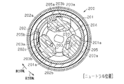
- the lock mechanism 200 includes a first member 201 fixed to the seat cushion constituent member, a second member 202 fixed to the seat back constituent member and rotatably supported by the first member 201, a plurality of poles 203, And a cam 204.
- the poles 203 are each guided so as to move in the radial direction by a plurality of guide grooves 201 a formed in the first member 201.
- Each pole 203 has external teeth 203 a that can be engaged with and disengaged from internal teeth 202 a provided on the second member 202.
- the cam 204 is rotatably provided on the first member 201, and in a state of unlocking operation accompanying the rotation in one direction, the plurality of poles 203 are drawn inward in the radial direction, and the external teeth 203a are engaged with the internal teeth 202a. In addition, the plurality of poles 203 are pressed radially outward in a locked state accompanying rotation in the other direction, and the external teeth 203a are engaged with the internal teeth 202a.
- the cam 204 is urged toward a locking direction by an urging member (not shown) and unlocked against the urging force of the urging member in an unlocking state of the operation member (not shown). It is rotated in the operating direction.
- the second member 202 is formed with a circular accommodating recess 202b that is coaxial with the internal teeth 202a.
- the housing recess 202b is provided with an annular memory ring 205 that is divided at one place so as to be rotatable in a reduced diameter state.
- a pair of adjacent poles 203 are provided with pole engaging protrusions 203b.
- the memory ring 205 has a divided portion located between both pole engaging protrusions 203b, and is positioned at a position adjacent to both pole engaging protrusions 203b with the movement of the pole 203 in the radial direction.
- the engaging protrusion 203b has a pair of engaged portions 205a and 205b to be engaged and disengaged.
- the memory ring 205 is radially engaged by the engaged portions 205a and 205b with respect to the pole engaging protrusion 203b of the pole 203 drawn inward in the radial direction.
- “half-engagement (or engagement) in the radial direction” means that a part (or the whole) of the pole engagement protrusion 203b of the pole 203 is partially (or entirely) in the radial direction with respect to the engaged portions 205a and 205b. It means that they overlap and thus interfere in the circumferential direction.
- the memory ring 205 rotates relative to the second member 202 integrally with the first member 201.
- the memory ring 205 is engaged in the radial direction of the engaged portion 205b with respect to the pole engaging protrusion 203b of the one pole 203 drawn inward in the radial direction.
- the match is released.
- the memory ring 205 rotates integrally with the second member 202 by frictional engagement with the second member 202 due to its own elastic deformation.
- the outer teeth 203a cannot mesh with the inner teeth 202a because the pole engaging protrusions 203b ride on the engaged portions 205b. That is, in the state of the second unlocking operation, the seat back that is allowed to tilt with respect to the seat cushion is tilted forward in the allowed state.
- the seat back in the tilt-allowed state is such that the engaged portion 205b passes through the pole engaging protrusion 203b of the pole 203, that is, the initial angular position of the second unlocking operation (hereinafter referred to as “memory”).
- the tilt can be regulated by returning to the “position”). That is, the tilt of the seatback that has been tilted forward in the state of the second unlocking operation is returned to the memory position when the forward tilt is resolved.
- the second member 202 is provided with a substantially fan-shaped engagement protrusion 202c protruding radially inward. That is, as shown in FIG. 27, the second member 202 is formed with a circular recess 202d coaxial with the inner teeth 202a on the inner peripheral side thereof. The recess 202d is arranged so that at least a part thereof overlaps with the pole engaging protrusion 203b at the position in the axial direction.
- the engaging protrusion 202c is projected from the inner peripheral surface of the recess 202d. As shown in FIG. 26, the engaging protrusion 202c can be engaged with both pole engaging protrusions 203b in the radial direction. Has been placed. In the state of the first unlocking operation, the engagement protrusion 202c is half-engaged in the radial direction with respect to the pole engagement protrusion 203b of the pole 203 drawn inward in the radial direction. In this case, “half-engagement (or engagement) in the radial direction” means that a part (or the whole) of the pole engagement protrusion 203b of the pole 203 overlaps the engagement protrusion 202c in the radial direction. Therefore, it means interference in the circumferential direction.
- the relative rotation of the first member 201 and the second member 202 is limited to a predetermined relative rotation range until the engagement protrusion 202c contacts the pole engagement protrusion 203b, and the seat back tilts. Is also limited to a predetermined angle range corresponding to the rotation range.
- the engagement protrusion 202c is configured such that the radial engagement of the pole 203 drawn inward in the radial direction with respect to the pole engagement protrusion 203b is released. Therefore, in the state of the second unlocking operation, the seat back can be tilted forward exceeding the predetermined angle range.
- the engagement protrusion 202c of the second member 202 (concave portion 202d) related to the setting of the predetermined angle range of the seat back is, as shown in FIG. 27, the memory ring 205 (accommodating concave portion 202b). Arranged from the position in the axial direction. Therefore, in the axial direction, the engaging protrusion 202c and the memory ring 205 are arranged on the second member 202 independently of each other, and the size in the axial direction is inevitably increased.
- An object of the present invention is to provide a vehicle seat reclining device that can be further downsized in the axial direction.
- a vehicle seat reclining device including a lock mechanism.
- the locking mechanism is fixed to one of a seat cushion constituent member and a seat back constituent member, and is fixed to the other of the first member having a guide groove, the seat cushion constituent member and the seat back constituent member, and the first member And a second member having inner teeth and guided by the guide groove of the first member so as to move in the radial direction and detachable from the inner teeth of the second member.
- a biasing member for urging the direction includes an operation member that rotates the cam in the unlocking direction against an urging force of the urging member in an unlocking operation state, and an elastic deformation state that reduces the diameter.
- a memory ring rotatably provided in a housing recess formed coaxially with the inner teeth on the second member, the first unlocking engagement surface formed on the inner peripheral surface of the memory ring, and the A first lock engagement surface formed on the inner peripheral surface adjacent to the first unlock engagement surface in the circumferential direction, the first pole having a first pole engagement protrusion;
- the first unlocking engagement surface engages with the first pole engagement protrusion so that the outer teeth of the first pole cannot mesh with the inner teeth, and the first lock engagement surface is the first pole engagement
- the engagement protrusion is released so that the external teeth of the first pole can be engaged with the internal teeth
- the memory ring has the first unlocking engagement surface and the first pole engaging protrusion with respect to the first pole engaging protrusion of the first pole drawn inward in the radial direction in the state of the first unlocking operation as the unlocking operation.
- the first member engaging the first pole engaging protrusion from the first locking engagement surface to the first unlocking engagement surface and corresponding to the seatback being tilted forward and
- the second member in a relative rotation state of the second member A memory ring that rotates integrally, an engagement protrusion that is provided in the housing recess of the second member and protrudes radially inward, and a rotation allowance formed on the outer peripheral surface of the memory ring. Prepare. When the rotation allowing portion allows the engagement protrusion to move, relative rotation between the second member and the memory ring is allowed within a predetermined rotation range.
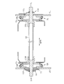
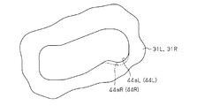
- FIG. 1 is a front view showing a vehicle seat device to which an embodiment of the present invention is applied.
- FIG. 2 is a cross-sectional view taken along line 2-2 in FIG. The side view which shows the vehicle seat apparatus and its operation
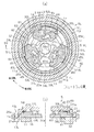
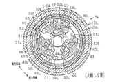
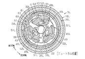
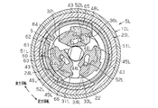
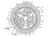
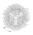
- FIG. 5A is a sectional view of the locking mechanism taken along the line 5A-5A in FIG. 1
- FIG. 5B is a sectional view taken along the line 5B-5B in FIG.
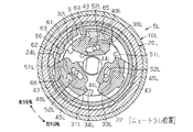
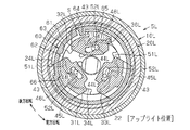
- FIG. 12 is a cross-sectional view of the locking mechanism taken along the line 12-12 in FIG. 1 in a locked state. Sectional drawing which shows the state of the 1st unlocking action
- the graph which shows the relationship between the rotation angle of a cam, and the sliding amount of a pole.
- Explanatory drawing which compares and shows a 1st and 2nd pole groove cam part.
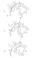
- the side view which shows the 1st operation member in the non-operation state of a 1st and 2nd operation member, and its surrounding structure.
- the side view which shows the 1st operation member in the 1st unlocking operation state of a 1st operation member, and its peripheral structure.
- FIG. 27 is a longitudinal sectional view showing the locking mechanism of FIG. 26.
- a vehicle seat device having a walk-in mechanism will be described with reference to FIGS.
- the front-rear direction, the width direction, and the up-down direction are the same as the corresponding directions in the vehicle.
- L and “R” may be attached
- a pair of lower rails 1 arranged in parallel in the width direction is fixed in a manner extending in the front-rear direction (direction orthogonal to the paper surface in FIG. 1).
- a pair of upper rails 2 are supported on the lower rails 1 so as to be movable in the front-rear direction.
- the lower rail 1 and the upper rail 2 constitute a seat slide mechanism, and are configured to selectively allow the movement of the upper rail 2 in the front-rear direction with respect to the lower rail 1 by a slide lock device (not shown).
- Both the upper rails 2 are mounted with a substantially square frame-like cushion frame 3 that forms a skeleton of a seat cushion.
- a pair of lower plates 4L and 4R made of a plate material are fixed to the cushion frame 3 by welding on the outer surfaces of the rear end portions of the pair of cushion side frames 3a constituting both sides in the width direction.
- the lower plates 4L and 4R correspond to seat cushion constituent members.
- the lower plate 4L, 4R is connected to a substantially square frame-like seat back frame 6 that forms a skeleton of the seat back via a pair of lock mechanisms 5L, 5R so as to be rotatable (tilted).
- the lock mechanism 5L corresponds to a first lock mechanism disposed on one side in the sheet width direction
- the lock mechanism 5R corresponds to a second lock mechanism disposed on the other side in the sheet width direction.
- the pair of back side frames 6a constituting both sides in the width direction of the seat back frame 6 has their lower end portions located inward in the width direction of the rear end portions (lower plates 4L and 4R) of the both cushion side frames 3a. Adjacent to each other.
- the back side frame 6a corresponds to a seat back constituent member.
- a pair of rod-like hinge shafts 91L and 91R having axial lines extending in the width direction penetrate through the lower ends of both backside frames 6a together with both lower plates 4L and 4R.
- Both the hinge shafts 91L and 91R support the members (second members 20L and 20R) on the back side frame 6a side of both the lock mechanisms 5L and 5R so as to be rotatable.
- the hinge shafts 91L and 91R are fixed so as to rotate integrally with a cylindrical connecting shaft 92 extending in the width direction coaxially with the hinge shafts 91L and 91R at the respective inner ends in the width direction. That is, the hinge shafts 91L and 91R rotate in conjunction with each other via the connecting shaft 92.
- the seatback frame 6 is connected to the lower plates 4L and 4R through the lock mechanisms 5L and 5R so as to be rotatable about the axis of the connection shaft 92 and the like. Thereby, the angle position (inclination angle) of the seat back with respect to the seat cushion can be adjusted.
- the lower plates 4L and 4R are provided with fixing flanges 7L and 7R extending outward in the width direction on the upper side of the hinge shafts 91L and 91R, and on the outer surface of the back side frame 6a.
- the inner end and the outer end of a spiral spring (not shown) are engaged with the fixed flanges 7L and 7R and the movable flanges 8L and 8R, respectively. This spiral spring is for urging the seat back in the forward tilt direction with respect to the seat cushion.
- the seat back (seat back frame 6) has the axes of the hinge shafts 91 ⁇ / b> L and 91 ⁇ / b> R in a range from a “forward position” that greatly tilts forward to a “large tilt position” that largely tilts backward.
- the seat cushion (seat cushion frame 3) can be tilted at the center.
- the lower plates 4L and 4R have upper portions that block the rotational trajectories of the movable flanges 8L and 8R on both sides in the circumferential direction around the axis of the hinge shafts 91L and 91R.
- a substantially claw-shaped front stopper 4a and rear stopper 4b are provided projecting radially outward.
- the angular position of the seat back (seat back frame 6) when the movable flanges 8L and 8R abut against the front stopper 4a corresponds to the forwardly tilted position, and the seat when the movable flanges 8L and 8R abut against the rear stopper 4b.
- the angular position of the back (seat back frame 6) corresponds to a position that is greatly overturned.
- the movable flanges 8L, 8R and the front stopper 4a constitute a front stopper mechanism.
- the tilting range of the seat back with respect to the seat cushion is roughly divided into a “forward tilt area” near the forward tilt position and an “adjustment area” near the large tilt position.
- the seat back is in an upright state.
- the lock mechanisms 5L and 5R described above mainly adjust and hold the angular position of the seat back with respect to the seat cushion in this adjustment region.
- the adjustment area is further divided into a “sitting area” near the upright position and a “non-sitting area” near the upright position.
- the angular position of the boundary between the seating area and the non-sitting area is referred to as “fixed point return position”.
- the seating area is a tilting range of the seat back suitable for a general sitting posture.For example, when the seat back is tilted forward from an arbitrary angular position of the seating area, the seat back is caused to move forward. By canceling, it is possible to return to the original angular position immediately before it was moved forward (full memory range).
- the non-sitting region is a seat back tilt range suitable for a special seating posture (e.g. a nap posture), for example, when the seat back is tilted forward from an arbitrary angular position of the non-sitting region, After that, the seat back is raised to eliminate the forward movement so that it can be installed at the fixed point return position (fixed point return range).
- a special seating posture e.g. a nap posture
- the predetermined angular position of the seat back (seat back frame 6) indicated by a solid line is the angular position of the seat back that is most frequently used when a general seated person is seated (hereinafter referred to as "neutral position"). It is.
- the forward tilting position of the forward tilting area is the angular position of the seat back for improving the ability to get on and off the seat on the rear seat side of the seat, and the slide lock device described above with the tilting of the seat back to the forward tilting position Is released, and the seat cushion is configured to slide forward relative to the vehicle floor.
- the vehicle seat device of the present embodiment has a so-called walk-in function.
- the lock mechanism 5L includes a disk-shaped first member 10L and a second member 20L.
- the first member 10L is concentric with the hinge shaft 91L (connection shaft 92) and fixed to the inner surface (seat cushion component) of the lower plate 4L by welding, and the second member 20L is similarly hinged on the hinge shaft 91L (connection shaft). It is concentric with the shaft 92) and fixed to the outer side surface (seat back component) of the lower end portion of the back side frame 6a by welding.
- the first member 10L and the second member 20L are prevented from coming off in the axial direction by a ring-shaped holder 29L made of a metal plate.
- the first member 10 ⁇ / b> L is formed, for example, by half blanking (half blanking) of a metal plate, and has an opening on the second member 20 ⁇ / b> L side.
- a circular recess 11 is formed.
- the recess 11 has an inner peripheral surface 11a centering on the axis of the hinge shaft 91L (the first member 10L and the second member 20L).
- each convex portion 12 forms guide walls 13 and 14 on both sides in the circumferential direction.
- the guide walls 13 and 14 facing each other in the circumferential direction of the adjacent convex portions 12 extend in parallel to each other in the radial direction centered on the axis, and have a diameter centered on the axis in cooperation with the bottom surface of the concave portion 11.
- a substantially U-shaped guide groove 15 extending in the direction is formed on the circumference at equal angular intervals. These guide grooves 15 communicate with each other at the center, and have a substantially Y shape as a whole.
- a substantially circular through hole 16 is formed in the central portion where the three guide grooves 15 of the first member 10L communicate.
- the through hole 16 is formed with a locking hole 16a radially outward at a predetermined angular position.
- the second member 20L is formed by, for example, half-cutting a metal plate, and has an outer diameter equivalent to the inner diameter of the inner peripheral surface 11a of the first member 10L. While having the outer peripheral surface 20a of a diameter, it has the circular recessed part 21 opened to the 1st member 10L side. Inner teeth 22 are formed over the entire circumference on the inner peripheral surface 21 a centering on the axis of the hinge shaft 91 ⁇ / b> L (the first member 10 ⁇ / b> L and the second member 20 ⁇ / b> L) of the recess 21. On the inner peripheral side of the recess 21, a substantially circular accommodation recess 23 is formed concentrically with the recess 21.
- a substantially arc-shaped engagement protrusion 24L that protrudes toward the center at a predetermined angular position is formed on the inner peripheral surface 23a of the housing recess 23, a substantially arc-shaped engagement protrusion 24L that protrudes toward the center at a predetermined angular position is formed.
- the second member 20L is fitted on the outer peripheral surface 20a so as to be in sliding contact with the inner peripheral surface 11a of the first member 10L.
- the outer peripheral portions of the first member 10L and the second member 20L are fitted with the inner peripheral surface 11a of the first member 10L and the outer peripheral surface 20a of the second member 20L.
- a holder 29L is attached.
- the first member 10L and the second member 20L are retained in the axial direction in a state where relative rotation is permitted by the holder 29L.
- first member 10L between the first member 10L and the second member 20L, three first poles 31L, 32L, 33L, a cam 34L, a spiral spring 35 as an urging member, a pressing member 36L, and a memory ring 60.
- the first poles 31L to 33L are mounted between two adjacent guide walls 13 and 14, and are arranged at equiangular intervals in the circumferential direction around the axis.
- the first poles 31L to 33L include a first block 41 and a second block 42 which are manufactured by forging a steel material and formed in steps different from each other in the axial direction.
- the first block 41 is disposed on the inner peripheral surface 21a side of the second member 20L in the radial direction
- the second block 42 is disposed on the axial center side of the second member 20L. Both width end portions of the first block 41 and the second block 42 coincide with each other and are formed to be parallel straight lines.
- Outer teeth 43 that can mesh with the inner teeth 22 of the second member 20L are formed on the arc-shaped outer ends of the first block 41 (end surfaces facing the inner teeth 22 of the second member 20L).
- the second block 42 is provided with a first pole groove cam portion 44L penetrating in the plate thickness direction at a substantially central portion in the width direction.
- the first poles 31L to 33L are guided to move in the radial direction around the axis line in such a manner that the width ends of the first poles 31L to 33L are in sliding contact with the guide walls 13 and 14, respectively. ing.
- the first poles 31L to 33L advance or retreat in the radial direction along both guide walls 13 and 14, thereby meshing or releasing (that is, disengaging) the outer teeth 43 and the inner teeth 22.
- the two first poles 31L and 33L have inner cam portions that engage with the outer peripheral portion of the cam 34L at the inner end of the first block 41 (the back surface that is the end surface opposite to the outer end). 45L is formed.
- the inner surface cam portion 45L formed at the step portion of the first poles 31L, 33L includes three pole cam surfaces 45aL, 45bL, 45cL on the circumferential center portion and both sides in the circumferential direction of the first poles 31L, 33L. ing. These pole cam surfaces 45aL, 45bL, and 45cL face the outer peripheral portion (cam surface 51L) of the cam 34L.
- the pole cam surfaces 45aL, 45bL, and 45cL have inclined surfaces that approach the outer peripheral portion of the cam 34L when the cam 34L is locked in accordance with rotation in the illustrated counterclockwise rotation direction (hereinafter also referred to as “lock rotation direction”). It consists of a cam surface.
- the first poles 31L and 33L have arc-shaped first pole engaging protrusions 46L on the radially outer side of the second block 42 so as to face the receiving recesses 23 (inner peripheral surface 23a) in the radial direction. Projected.
- the first pole engaging protrusion 46L is disposed at the center in the circumferential direction of the first poles 31L and 33L.
- the remaining one first pole 32L has an inner cam portion 47L that engages with the outer peripheral portion of the cam 34L at the inner end of the first block 41 (the rear surface that is the end surface opposite to the outer end). Is formed.
- the inner surface cam portion 47L formed in the step portion of the first pole 32L includes pole cam surfaces 47aL and 47bL similar to the pole cam surfaces 45aL and 45bL, and a pole cam surface 47cL instead of the pole cam surface 45cL.
- the pole cam surface 47cL faces the outer peripheral portion (cam surface 51L) of the cam 34L, and is shaped so as to form a wedge-shaped space with the guide wall 13 facing in the circumferential direction. That is, the distance between the guide wall 13 and the pole cam surface 47cL is formed so as to become narrower toward the outer side in the radial direction.
- first pole 32L is provided with an arc-shaped first pole engaging protrusion 48L on the outer side in the radial direction of the second block 42 so as to face the accommodation recess 23 (inner peripheral surface 23a) in the radial direction.
- the first pole engaging protrusion 48L is arranged at a site on the side preceding the clockwise rotation in the figure in the circumferential direction of the first pole 32L.
- the cam 34L is disposed so as to be rotatable about the axis of the second member 20L on the inner peripheral side of the first poles 31L to 33L in the recess 21 of the second member 20L. That is, the cam 34L is manufactured by pressing a plate-shaped steel plate or the like, and basically has a flat plate shape having no step. A substantially oval cam fitting hole 34a is formed in the center of the cam 34L so as to penetrate in the plate thickness direction along the axis.
- the cam 34L is rotated integrally with a member such as the hinge shaft 91L on the inner peripheral side of the first poles 31L to 33L (first block 41) by inserting the tip of the hinge shaft 91L into the cam fitting hole 34a. It is possible to move.
- the cam 34L has three sets of cam surfaces 51L at equiangular intervals on the outer periphery thereof.
- Each cam surface 51L includes three pressing cam portions 51aL, 51bL, and 51cL on the circumferential center portion and both circumferential sides.
- the two pressing cam portions 51aL and 51bL can abut against the two pole cam surfaces 45aL and 45bL facing the first poles 31L and 33L or the two pole cam surfaces 47aL and 47bL facing the first pole 32L. is there.
- These two pressing cam portions 51aL and 51bL press the corresponding pole cam surfaces 45aL, 45bL, 47aL, and 47bL when the cam 34L is rotated in the lock rotation direction.
- the remaining one of the pressing cam portions 51cL can be in contact with the remaining pole cam surface 45cL facing the first poles 31L and 33L, and when the cam 34L is rotated in the lock rotation direction.
- the corresponding pole cam surface 45cL is pressed.
- the pressing cam portion 51cL accommodates the spherical pressing member 36L in the aforementioned wedge-shaped space formed between the pole cam surface 47cL of the first pole 32L and the guide wall 13.
- the pressing member 36 ⁇ / b> L can move in the radial direction while being in sliding contact with the pole cam surface 47 c ⁇ / i> L and the guide wall 13.
- the pressing cam portion 51cL can circumscribe the pressing member 36L, and presses the pressing member 36L when the cam 34L is rotated in the lock rotation direction.
- the pressing cam portions 51aL to 51cL are connected to the pole cam surfaces 45aL to 45cL of the first poles 31L and 33L, the pole cam surfaces 47aL and 47bL of the first pole 32L, and the pressing when the cam 34L is rotated in the lock rotation direction.
- the members 36L are held at angular positions where they abut (ie, press contact) with each other.
- the pressing member 36L is pressed against the guide wall 13 and the pole cam surface 47cL by being pressed by the cam 34L.
- the pressing force of the pressing member 36L includes a component force of a moving direction component (radial component) of the first pole 32L and a component force of a pole width direction component (circumferential component) which is a direction orthogonal to the moving direction. Is broken down into Then, the wedge action caused by pressing with the component of the width direction component of the first pole 32L generates a circumferential force in which the width end portion of the first pole 32L and the guide wall 13 are separated from each other. The gap between the 32 L width end and the guide wall 14 is filled. Thereby, rattling of the seat back with respect to the seat cushion is suppressed.
- the pressing cam portions 51aL and 51bL have the pole cam surfaces 45aL of the first poles 31L and 33L. , 45bL or the first cam 32L is separated from the pole cam surfaces 47aL, 47bL. Further, the pressing cam portion 51cL is separated from the pole cam surface 45cL of the first poles 31L and 33L, or is separated from the pressing member 36L.
- a plurality (three) of engaging projections 52L are provided on the side surface of the cam 34L at intervals on the circumference. These engagement protrusions 52L are inserted and engaged with the first pole groove cam portions 44L of the first poles 31L to 33L. The first pole groove cam portion 44L and the engagement protrusion 52L act so as to move the first poles 31L to 33L radially inward by the rotation of the cam 34L in the unlock rotation direction.
- the first pole groove cam portion 44L basically advances gradually outward in the radial direction as it goes in the unlocking rotation direction (clockwise rotation direction in the drawing) of the cam 34L. Molded. As a result, as the cam 34L rotates in the unlocking direction, the first poles 31L to 33L pressed by the first pole groove cam portion 44L are drawn inward in the radial direction into the engagement protrusion 52L.
- the spiral spring 35 urges the cam 34L in the lock rotation direction so as to move the first poles 31L to 33L in the radial direction engaged with the second member 20L. Is stored in the through hole 16.
- the spiral spring 35 is formed, for example, by bending a substantially rectangular flat wire rod into a predetermined spiral shape, and is interposed between the first member 10L and the cam 34L. That is, the outer end portion 35a of the spiral spring 35 is locked to the locking hole 16a, and the inner end portion 35b is locked to a locking portion (not shown) protruding from the end surface of the cam 34L.
- the cam 34L is urged in the lock rotation direction (counterclockwise rotation direction in FIG. 5A) by the urging force of the spiral spring 35, and the first pole 31L ⁇
- the outer teeth 43 are pressed radially outward to engage the outer teeth 43 with the inner teeth 22 of the second member 20L.
- the memory ring 60 has an annular shape divided at one place, and can be reduced in diameter by being elastically deformed radially inward. In addition, the diameter can be increased by elastically returning toward the radially outer side.
- the memory ring 60 is located in the receiving recess 23 of the second member 20L in a state in which the divided portion S is positioned between the first pole engaging protrusions 46L and 48L of the adjacent first poles 31L and 32L and is reduced in diameter. On the other hand, it is slidable in the circumferential direction, that is, is rotatably accommodated.
- the memory ring 60 has a relatively reduced diameter near the first pole 31L with the divided portion S interposed therebetween, and the arc-shaped outer peripheral surface and inner peripheral surface of the portion are the rotation allowing portion 61 and the first peripheral portion.
- An unlocking engagement surface 62 is formed.
- the memory ring 60 has an arc-shaped fixed point returning projection 63 that projects radially inward from the circumferential center of the first unlocking engagement surface 62.
- the memory ring 60 forms an engaged portion 64 by projecting an end portion closer to the first pole 32L (first pole engaging protrusion 48L) toward the inside in the radial direction with the divided portion S interposed therebetween. Regardless of the position of the first pole 32L that moves in the radial direction along the guide groove 15, the engaged portion 64 is set so as to always overlap the first pole engaging protrusion 48L in the radial position. Yes. Therefore, when the engaged portion 64 is adjacent to the first pole engaging protrusion 48L, the memory ring 60 rotates in the illustrated clockwise direction with respect to the first pole 32L, that is, in the illustrated clockwise direction with respect to the first member 10L. The rotation of is always regulated.
- the arc-shaped inner circumferential surface sandwiched between the first unlocking engagement surface 62 and the engaged portion 64 of the memory ring 60 is a first locking engagement having an inner diameter larger than the inner diameter of the first unlocking engagement surface 62.
- Surface 65 is formed.
- the boundary position (step) between the first unlocking engagement surface 62 and the first locking engagement surface 65 is, for example, when the first pole 31L is moving radially outward along the guide groove 15, that is, the first pole.
- the first pole engagement protrusions 46L located on the first lock engagement surface 65 are always overlapped with each other in the radial position.
- the memory ring 60 is always restricted from rotating in the illustrated counterclockwise direction with respect to the first pole 31L, that is, in the illustrated counterclockwise direction with respect to the first member 10L.
- a stepped boundary position between the first unlocking engagement surface 62 and the first locking engagement surface 65 forms a regulation surface 66.
- the memory ring 60 is semi-engaged with the first pole engaging protrusion 46L in the radial direction on the regulating surface 66, thereby rotating in the counterclockwise direction shown in the figure with respect to the first pole 31L, that is, The rotation in the illustrated counterclockwise rotation direction with respect to the first member 10L is always restricted.
- the unlocking operation of the cam 34L at this time is also referred to as a first unlocking operation.
- the engaging protrusion 24L provided on the second member 20L is disposed in the rotation allowing portion 61 in the circumferential direction. Therefore, when the rotation of the memory ring 60 with respect to the first member 10L is restricted, the engagement protrusion 24L (second member 20L) is allowed to rotate within the range of the rotation allowing portion 61. . 5A and 6 illustrate a state when the seat back is in the neutral position.
- the second member 20 ⁇ / b> L that rotates counterclockwise in the illustrated direction with respect to the memory ring 60 (and the first member 10 ⁇ / b> L) in a state where the engagement of the external teeth 43 and the internal teeth 22 is released.
- the rotation of the engaging protrusion 24 ⁇ / b> L is restricted when it reaches the end of the rotation allowing portion 61.
- the rotation of the second member 20L with respect to the first member 10L at this time tilts the seat back forward with respect to the seat cushion, and is also referred to as forward rotation below. Therefore, the state in which the engaging protrusion 24L reaches the end of the rotation allowing portion 61 in the forward rotation of the second member 20L corresponds to the upright position of the seat back.
- the second member 20 ⁇ / b> L that rotates in the illustrated clockwise direction with respect to the memory ring 60 (and the first member 10 ⁇ / b> L) in a state where the engagement of the external teeth 43 and the internal teeth 22 is released is
- the engaging protrusion 24L reaches the end of the rotation allowing portion 61
- the rotation is restricted.
- the rotation of the second member 20L with respect to the first member 10L at this time causes the seat back to tilt backward with respect to the seat cushion, and is hereinafter also referred to as backward rotation. Therefore, the state in which the engagement protrusion 24L reaches the end of the rotation allowing portion 61 in the rearward rotation of the second member 20L corresponds to the seatback greatly tilted position.
- the restricting surface 66 has the first pole engaging protrusion. It is set so as not to overlap with the portion 46L at the radial position. Accordingly, at this time, the memory ring 60 is released from the radial engagement with the first pole engaging protrusion 46L on the restricting surface 66, so that the rotation in the illustrated counterclockwise direction with respect to the first pole 31L, that is, The first member 10L is allowed to rotate in the illustrated counterclockwise direction. At the same time, the memory ring 60 can rotate integrally with the second member 20L by frictional engagement with the second member 20L by its own elastic deformation.
- the memory ring 60 starts to rotate integrally while maintaining the relative position with respect to the second member 20L. Then, the first pole engaging protrusion 46L located on the restricting surface 66 rides from the first lock engaging surface 65 to the first unlock engaging surface 62 accordingly. At this time, the movement of the first pole 31L in the state of disengagement with the inner teeth 22 is restricted to the radially outer side by the first unlocking engagement surface 62 on which the first pole engaging protrusion 46L rides. Thus, the release state is maintained. The same applies to the other first poles 32L and 33L linked via the cam 34L. The unlocking operation of the cam 34L at this time is also referred to as a second unlocking operation.
- the angular position at which the backward tilt of the seat back is restricted coincides with the initial angular position (hereinafter also referred to as a “memory position”) at which the seat back starts to tilt forward with the second unlocking operation of the cam 34L. To do.
- the memory ring 60 is engaged with the first pole engaging protrusion 46L in the radial direction at the fixed point returning protrusion 63, whereby the memory ring 60 rotates in the illustrated counterclockwise direction with respect to the first pole 31L, that is, the first The rotation in the illustrated counterclockwise direction with respect to the member 10L is again restricted. That is, the rotation of the memory ring 60 relative to the first member 10L is always restricted, and the memory ring 60 can rotate relative to the second member 20L. In other words, the memory ring 60 still maintains the contact state of the fixed point return projection 63 and the first pole engagement projection 46L even when the seat back reaches the forward position.
- the second member 20L rotates backward together with the memory ring 60, and the first lock engagement surface 65 reaches the first pole engagement protrusion 46L.
- One pole 31L can mesh with the internal teeth 22.
- Other first poles 32L. Linked with the cam 34L. The same applies to 33L. Further, when the first poles 31L to 33L are engaged with the inner teeth 22, further rearward rotation of the second member 20L together with the memory ring 60 is restricted.
- the rotation amount of the second member 20L with respect to the first member 10L at this time coincides with a predetermined angle corresponding to the angle between the restricting surface 66 and the fixed point return projection 63. That is, the angular position where the backward tilt of the seat back is restricted coincides with the angular position tilted backward by the predetermined angle from the forward position.
- the above-mentioned fixed point return position of the seat back corresponds to the angular position to be returned at this time. In other words, if the amount of rotation of the second member 20L relative to the first member 10L when the seat back is tilted forward to the forward position exceeds the predetermined angle, that is, the angular position when the forward movement of the seat back is started.
- the lock mechanism 5R includes a disk-shaped first member 10R and a second member 20R.
- the first member 10R is concentric with the hinge shaft 91R (connection shaft 92) and fixed to the inner side surface (seat cushion component) of the lower plate 4R by welding, and the second member 20R is similarly hinged on the hinge shaft 91R (connection shaft). It is concentric with the shaft 92) and fixed to the outer side surface (seat back component) of the lower end portion of the back side frame 6a by welding.
- the first member 10R and the second member 20R are prevented from coming off in the axial direction by a ring-shaped holder 29R made of a metal plate.
- the first member 10R is formed, for example, by half blanking (half blanking) of a metal plate, and has substantially the same structure as the first member 10L except for being symmetrical. .
- the second member 20R is formed by, for example, half-cutting a metal plate, and has substantially the same structure as the second member 20L except that it is bilaterally symmetric.
- a plurality (three) of substantially arc-shaped engaging protrusions 24 ⁇ / b> R arranged at equiangular intervals protrude from the inner peripheral surface 23 a of the housing recess 23 toward the center.
- the second member 20R forms the second unlocking engagement surface 26 on the inner peripheral surface of the engagement protrusion 24R, and the second lock engagement surface 27 on the inner peripheral surface 23a between the adjacent engagement protrusions 24R.
- the second poles 31R, 32R, 33R, a cam 34R, a pressing member 36R, and the spiral spring 35 are disposed between the first member 10R and the second member 20R.
- the second poles 31R to 33R are manufactured by forging a steel material or the like, and have substantially the same structure as the first poles 31L to 33L except that they are symmetrical.
- the second block 42 is provided with a second pole groove cam portion 44R penetrating in the plate thickness direction at a substantially central portion in the width direction.
- the second poles 31R to 33R are provided with arc-shaped second pole engaging protrusions 46R on the radially outer side of the second block 42 so as to face the receiving recesses 23 (inner peripheral surface 23a) in the radial direction. Projected.
- the second pole engaging protrusion 46R is disposed at the center in the circumferential direction of the second poles 31R to 33R.
- the two second poles 31R and 33R have inner cam portions that engage with the outer peripheral portion of the cam 34R at the inner end of the first block 41 (the rear surface that is the end surface opposite to the outer end). 45R is formed.
- the inner surface cam portion 45R formed at the step portion of the second poles 31R and 33R includes three pole cam surfaces 45aR, 45bR, and 45cR on the circumferential center portion and both sides in the circumferential direction of the second poles 31R and 33R. ing. These pole cam surfaces 45aR, 45bR, and 45cR face the outer peripheral portion (cam surface 51R) of the cam 34R.
- the pole cam surfaces 45aR, 45bR, and 45cR have inclined surfaces that approach the outer peripheral portion of the cam 34R when the cam 34R is locked in accordance with rotation in the illustrated counterclockwise rotation direction (hereinafter also referred to as “lock rotation direction”). It consists of a cam surface.
- the remaining one second pole 32R has an inner surface cam portion 47R that engages with the outer peripheral portion of the cam 34R at the inner end of the first block 41 (the back surface that is the end surface opposite to the outer end). Is formed.
- the inner surface cam portion 47R formed at the step portion of the second pole 32R includes pole cam surfaces 47aR and 47bR similar to the pole cam surfaces 45aR and 45bR, and a pole cam surface 47cR instead of the pole cam surface 45cR.
- the pole cam surface 47cR faces the outer peripheral portion (cam surface 51R) of the cam 34R, and is shaped so as to form a wedge-shaped space with the guide wall 13 facing in the circumferential direction. That is, the distance between the guide wall 13 and the pole cam surface 47cR is formed so as to become narrower toward the outer side in the radial direction.
- the cam 34R is manufactured by pressing a plate-shaped steel plate and has substantially the same structure as the cam 34L except that it is symmetrical.
- the cam 34R can be rotated integrally with the hinge shaft 91R on the inner peripheral side of the second poles 31R to 33R by fitting the tip end portion of the hinge shaft 91R into the cam fitting hole 34a.
- the left and right cams 34L, 34R (lock mechanisms 5L, 5R) are coupled to operate in synchronization with each other via the hinge shafts 91L, 91R and the coupling shaft 92.
- the cam 34R has three sets of cam surfaces 51R at equiangular intervals on the outer periphery thereof.
- Each cam surface 51R includes three pressing cam portions 51aR, 51bR, and 51cR on the circumferential center portion and both sides in the circumferential direction.
- the two pressing cam portions 51aR and 51bR can contact the two pole cam surfaces 45aR and 45bR facing the second poles 31R and 33R or the two pole cam surfaces 47aR and 47bR facing the second pole 32R. is there.
- the two pressing cam portions 51aR and 51bR press the corresponding pole cam surfaces 45aR, 45bR, 47aR, and 47bR when the cam 34R is rotated in the lock rotation direction.
- the remaining one of the pressing cam portions 51cR can be brought into contact with the remaining pole cam surface 45cR facing the second poles 31R and 33R, and when the cam 34R is rotated in the lock rotation direction.
- the corresponding pole cam surface 45cR is pressed.
- the pressing cam portion 51cR accommodates the spherical pressing member 36R in the aforementioned wedge-shaped space formed between the pole cam surface 47cR of the second pole 32R and the guide wall 13.
- the pressing member 36 ⁇ / b> R can move in the radial direction while being in sliding contact with the pole cam surface 47 c ⁇ / i> R and the guide wall 13.
- the pressing cam portion 51cR can circumscribe the pressing member 36R, and presses the pressing member 36R when the cam 34R is rotated in the lock rotation direction.
- the pressing cam portions 51aR to 51cR are connected to the pole cam surfaces 45aR to 45cR of the second poles 31R and 33R, the pole cam surfaces 47aR and 47bR of the second pole 32R, and the pressing cam portions 51aR to 51cR.
- the members 36R are held at angular positions where they abut (pressure contact) with each other.
- the pressing member 36R is pressed against the guide wall 13 and the pole cam surface 47cR by being pressed by the cam 34R.
- the pressing force of the pressing member 36R includes a component force of a moving direction component (radial component) of the second pole 32R and a component force of a pole width direction component (circumferential component) which is a direction orthogonal to the moving direction. Is broken down into Then, the wedge action caused by pressing with the component of the width direction component of the second pole 32R generates a circumferential force in which the width end portion of the second pole 32R and the guide wall 13 are separated from each other. The gap between the width end portion of 32R and the guide wall 14 is filled. This is for suppressing rattling of the seat back with respect to the seat cushion.
- the pressing cam portions 51aR and 51bR are connected to the second pole during the unlocking operation accompanying the rotation of the cam 34R in the illustrated clockwise rotation direction (hereinafter also referred to as “unlock rotation direction”). It is separated from the pole cam surfaces 45aR and 45bR of 31R and 33R or the pole cam surfaces 47aR and 47bR of the second pole 32R. Further, the pressing cam portion 51cR is separated from the pole cam surface 45cR of the second poles 31R and 33R, or is separated from the pressing member 36R.
- a plurality (three) of engaging projections 52R are provided on the side surface of the cam 34R at intervals on the circumference. These engagement protrusions 52R are inserted and engaged with the second pole groove cam portions 44R of the second poles 31R to 33R. The second pole groove cam portion 44R and the engagement protrusion 52R act to move the second poles 31R to 33R radially inward by the rotation of the cam 34R in the unlocking rotation direction.
- the second pole groove cam portion 44R is shaped so as to gradually advance radially outward as it goes in the unlocking rotation direction (clockwise rotation direction) of the cam 34R. Yes.
- the cam 34R rotates in the unlocking rotation direction
- the second poles 31R to 33R pressed by the second pole groove cam portion 44R are drawn inward in the radial direction into the engagement protrusion 52R.
- the cam 34R is urged in the lock rotation direction (counterclockwise rotation direction in FIG. 12) with respect to the first member 10R by the urging force of the spiral spring 35, and the second poles 31R to 33R are urged by the cam surface 51R.
- the outer teeth 43 are pressed radially outward to engage the inner teeth 22 of the second member 20R.
- the unlocking operation of the cam 34R at this time is also referred to as a first unlocking operation.
- the engagement protrusion 24R has a second pole engagement protrusion 46R.
- the rotation is regulated by reaching.
- the rotation of the second member 20R relative to the first member 10R at this time is a forward rotation.
- the engagement protrusion 24R has the second pole engagement.
- the rotation is regulated by reaching the protrusion 46R.
- the rotation of the second member 20R relative to the first member 10R at this time is a backward rotation.
- the second member 20R is released from the radial engagement with the second pole engaging protrusion 46R in the engaging protrusion 24R, for example, in the illustrated clockwise rotation with respect to the second poles 31R to 33R. Further rotation in the direction, that is, further rotation in the illustrated clockwise rotation direction with respect to the first member 10R is allowed.
- the second pole engagement protrusion 46R located on the second lock engagement surface 27 is accompanied by the second pole engagement protrusion 46R.
- the second lock engagement surface 27 rides onto the second unlock engagement surface 26.
- movement of the second poles 31R to 33R in the disengagement state with the inner teeth 22 is restricted by the second unlock engagement surface 26 on which the second pole engagement protrusion 46R rides outward.
- the release state is maintained. Accordingly, the forward rotation of the second member 20R at this time is allowed until it reaches a rotational position corresponding to the forward position of the seat back.
- the unlocking operation of the cam 34R at this time is also referred to as a second unlocking operation.
- the second member 20R rotates backward, and when the second lock engagement surface 27 reaches the second pole engagement protrusion 46R, the second pole 31R ⁇ 33R can mesh with the internal teeth 22.
- the first poles 31L to 33L on the opposite side interlocked via the connecting shaft 92 must be able to mesh with the inner teeth 22. That is, the operation when the second poles 31R to 33R mesh with the internal teeth 22 is restricted by the operation of the first poles 31L to 33L on the opposite side related to the return to the memory position.
- the tip of the hinge shaft 91R protruding in the axial direction from the lower plate 4R on one side is linked to a first operation member 71 made of, for example, a plate material, and the first operation
- the cam 34R connected to the hinge shaft 91R is rotated in the direction of the first unlocking operation when the tip end of the member 71 is pulled up (hereinafter also referred to as “first unlocking operation”). It is configured.
- the cam 34L on the opposite side also rotates in the first unlocking direction via the connecting shaft 92 and the hinge shaft 91L.
- an attachment member 6b that extends to the corner of the seat back frame 6 is provided on the shoulder at the upper left of the figure.
- An arm-like second operation member 72 made of, for example, a plate material is supported on the attachment member 6b by a shaft 73 so as to be rotatable in the vertical direction.
- the second operating member 72 is always urged downward by a return spring (not shown).
- stoppers 74a and 74b are provided on the upper side and the lower side of the second operation member 72, and the operation range of the second operation member 72 is defined by these stoppers 74a and 74b. Yes.
- the tip of the hinge shaft 91L protruding in the axial direction from the lower plate 4L on one side is linked to a release link 100 made of, for example, a plate material.
- the distal end portion of the release link 100 is connected to the intermediate portion in the longitudinal direction of the second operation member 72 via a cable 75 guided in the outer tube T of a flexible double tube cable, for example.
- the direction in which the cam 34L connected to the hinge shaft 91L performs the second unlocking operation when the distal end portion of the second operating member 72 is pulled up (hereinafter also referred to as “second unlocking operation”). It is comprised so that it may rotate.
- the cam 34R on the opposite side also rotates in the second unlocking direction via the connecting shaft 92 and the hinge shaft 91R.
- outer cylinder T of the cable 75 is held by a cable holder 6c formed on the attachment member 6b at one end, and held by the cable holder 104 fixed to the lower plate 4L.
- illustration of the cable 75 and the intermediate part of the outer cylinder T is omitted.
- the cam when the external teeth 43 of the first pole 31L and the second pole 31R and the internal teeth 22 of the second members 20L and 20R are in mesh with each other due to the urging force of the spiral spring 35.
- the sliding angle which is the amount of movement of the cams 34L and 34R in the radial direction separated from the internal teeth 22 of the first pole 31L and the second pole 31R corresponding to the rotation angle ⁇ of the cams 34L and 34R with the rotation angle of 34L and 34R as the origin.
- the relationship with the quantity SL will be described.
- the other first poles 32L and 33L and the second poles 32R and 33R are linked to the first pole 31L and the second pole 31R, respectively, and the description thereof is omitted.
- the rotation angle ⁇ 1 represents the rotation angle ⁇ corresponding to the maximum operation amount when the first operation member 71 is first unlocked, and the rotation angle ⁇ 2 (> ⁇ 1) is the second operation amount.
- the rotation angle ⁇ corresponding to the maximum operation amount when the operation member 72 of the second is unlocked. Therefore, the rotation angle ⁇ 2 matches the rotation angle ⁇ of the cam 34L corresponding to the operation amount at which the second operation member 72 contacts the stopper 74a.
- the slide amount S1 represents the transition of the slide amount SL of the first pole 31L when the cams 34L and 34R are unlocked, and the slide amount S2 is the second unlock of the cams 34L and 34R. The transition of the slide amount SL of the second pole 31R during operation is shown.
- the rotation angle ⁇ 3 is the rotation when the engaging projections 52L and 52R come into contact with the first pole engaging protrusion 46L and the second pole engaging protrusion 46R through the idle running section when the cams 34L and 34R are unlocked.
- the angle ⁇ is represented.
- the rotation angle ⁇ 4 represents the rotation angle ⁇ corresponding to the sliding amount Sr when the external teeth 43 of the first pole 31L and the second pole 31R and the internal teeth 22 of the second members 20L and 20R release the tooth tips. ing.
- the slide amount S3 is the amount of the slide amount SL when the external teeth 43 of the first pole 31L and the second pole 31R mesh with the internal teeth 22 of the second members 20L and 20R by the urging force of the spiral spring 35. It represents the transition. That is, when the external teeth 43 of the first pole 31L and the second pole 31R mesh with the internal teeth 22 of the second members 20L and 20R, the slide amount SL is set to change equally. The transition of the slide amount SL at this time is adjusted and set by the shapes of the cam surfaces 51L and 51R of the cams 34L and 34R and the inner surface cam portions 45L and 45R of the first pole 31L and the second pole 31R.
- the slide amounts S1 and S2 indicate that the cams 34L and 34R start the second unlocking operation and the external teeth 43 of the first pole 31L and the second pole 31R and the second members 20L and 20R. Initially, when the inner teeth 22 finish the tooth tip release, the slide amount SL is set to change equally.
- the second pole engaging projection 46R of the second pole 31R is set so as to change differently around the second unlocking engaging surface 26 of the second member 20R. That is, the slide amount St1 when the first pole engagement protrusion 46L of the first pole 31L rides on the first unlock engagement surface 62 of the memory ring 60 is the second pole engagement protrusion 46R of the second pole 31R. Is set to be larger than the sliding amount St2 when riding on the second unlocking engagement surface 26 of the second member 20R. This is because, for example, the rotation angle ⁇ (the amount of operation of the first operating member 71 when the first pole engaging protrusion 46L of the first pole 31L rides on the first unlocking engaging surface 62 of the memory ring 60 due to component variation.
- the memory ring 60 is integrally rotated with the second member 20L, that is, the memory position is set, but the seat is set. It is possible to prevent the forward tilting of the back exceeding the predetermined angle range from being disabled.
- the first increase with respect to the increase amount of the rotation angle ⁇ is set to be larger than the increase amount of the slide amount S2 of the second pole 31R. That is, the radial movement speed at which the first pole 31L is separated from the inner teeth 22 is set to be higher than the radial movement speed at which the second pole 31R is separated from the inner teeth 22.
- the transition of the slide amount SL when the pole engaging protrusion 46R rides on the second unlocking engagement surface 26 of the second member 20R is the first pole in which the engaging protrusions 52L and 52R of the cams 34L and 34R are engaged. It is adjusted and set according to the shape of the groove cam portion 44L and the second pole groove cam portion 44R.
- the drawing relates to the drawing of the first pole 31L in the vicinity of the second pole engaging protrusion 46R of the second pole 31R riding on the second unlocking engagement surface 26 of the second member 20R, which is drawn by a solid line in FIG.
- the inner wall surface 44aL of the first pole groove cam portion 44L is drawn on the outer side in the radial direction with respect to the inner wall surface 44aR of the second pole groove cam portion 44R similarly drawn in FIG. It is raised. Thereby, the relative increase in the moving speed in the radial direction in which the first pole 31L is separated from the inner teeth 22 is realized.
- the first operation member 71 is formed in a substantially bow shape, and is rotatably supported at the distal end portion of the hinge shaft 91R.
- the first operating member 71 has a movable stopper 71a protruding from the base end portion thereof to the front upper side substantially along the radial direction centering on the hinge shaft 91R.
- This movable stopper 71a is disposed on the side preceding the fixed flange 7R in the clockwise direction in the figure centering on the hinge shaft 91R, and is disposed so that the rotation locus is blocked by the fixed flange 7R.
- the first operating member 71 is biased and held (pulled) at a predetermined initial rotation position by a return spring 76 stretched between the first operating member 71 and the lower plate 4R.
- the maximum rotation range when the tip of the first operating member 71 is pulled up (first unlocking operation) is the range until the movable stopper 71a contacts the fixed flange 7R. Limited to range. At this time, the rotation angle ⁇ corresponding to the operation amount of the first operation member 71 coincides with the rotation angle ⁇ 1.
- the tip of the hinge shaft 91R is fitted and fixed to a link member 80 made of a plate material adjacent to the outside of the first operating member 71 on the lower side of the fixed flange 7R. ing.
- An arc-shaped long hole 81 centering on the hinge shaft 91R is formed at the distal end of the link member 80.
- a pin 77 that is slidably inserted into the long hole 81 is fixed to the first operation member 71.
- the first operation member 71 is rotatably supported with respect to the tip end portion of the hinge shaft 91R, and is biased and held at a predetermined initial rotation position by the return spring 76.
- the link member 80 is normally urged in the rotation direction (clockwise rotation in FIG. 17) in which the cam 34R integral with the hinge shaft 91R is locked by the spiral spring 35, so that the link member 80 is normally in the initial rotation position. It is arranged at a position where one end (front end) of the long hole 81 is locked to the pin 77 of a certain first operating member 71.
- the release link 100 is formed in a substantially L shape, and the distal end portion of the hinge shaft 91 ⁇ / b> L is fitted and fixed.
- the release link 100 is always urged in the rotational direction (counterclockwise rotational direction in FIG. 20) in which the cam 34L integral with the hinge shaft 91L is locked by the spiral spring 35, and together with them, usually the predetermined link It is held at the initial rotation position.
- an arc-shaped elongated hole 101 centering on the hinge shaft 91L is formed at the distal end portion of the release link 100.
- a terminal 75 a of a cable 75 extending from the second operation member 72 is slidably inserted into the long hole 101.
- the terminal 75 a of the cable 75 is located at one end (lower end) of the long hole 101.
- a cable holder 104 for holding the end of the outer cylinder T is fixed to the lower end portion of the lower plate 4L.
- the cable 75 is pulled downward, so that the release link 100 is connected to one end (lower end) of the long hole 101 by the terminal 75a. Is pressed to rotate in the clockwise direction in the figure.
- the hinge shaft 91L rotates integrally in the same direction.
- the cam 34L integrated with the hinge shaft 91L performs the second unlocking operation against the urging force of the spiral spring 35.
- the release link 100 is rotated in the clockwise direction in the drawing, the movement of the terminal 75a within the elongated hole 101 is allowed, so that the release link 100 is rotated by the cable 75 or the second There is no transmission to the operating member 72.
- the release link 100 rotates together with them. Move. At this time, as described above, the movement of the terminal 75a in the long hole 101 is allowed, so that the rotation of the release link 100 is not transmitted to the second operation member 72.
- the link member 80 rotates together with them. Move. At this time, the rotation of the link member 80 is not transmitted to the first operation member 71 because the movement of the pin 77 within the long hole 81 is allowed as described above.
- a substantially arcuate switching piece 102 extending in the circumferential direction around the hinge shaft 91 ⁇ / b> L is formed at the middle in the longitudinal direction of the release link 100.
- the outer peripheral surface of the base end portion of the switching piece 102 forms an operation restricting surface 102a as a circular first cam surface centered on the hinge shaft 91L.
- the outer peripheral surface of the distal end portion of the switching piece 102 forms a substantially linear operation permissible surface 102b that goes to the inner peripheral side rather than the circle along which the operation restricting surface 102a extends as it goes to the front end.
- the switching piece 102 prevents the seat back from being tilted back at a fixed point return position (predetermined regulation angle position).
- the stopper mechanism 110 to be regulated is configured.
- the stopper mechanism 110 includes the movable flange 8L, the switching piece 102, and the upper rear portion of the lower plate 4L above the switching piece 102 (ie, in the vicinity of the rear stopper 4b).
- the stopper link 112 and the stopper link urging member 113 are connected to each other by a pin 111 so as to be rotatable.
- the stopper link 112 is made of, for example, a plate material.
- the stopper link 112 includes a substantially arcuate stopper piece 112a that extends toward the movable flange 8L substantially along a circumferential direction centered on the hinge shaft 91L, and faces the release link 100 (switching piece 102). And a substantially bay-shaped engagement surface 112b as a second cam surface extending downward.
- the stopper link 112 is basically configured such that further rotation is restricted by the engagement surface 112b coming into contact with the outer peripheral surface of the switching piece 102 when rotating around the pin 111 in the clockwise direction shown in the figure. It has become.
- the stopper link urging member 113 is made of, for example, a torsion coil spring, and one end is locked to the pin 111 fixed to the lower plate 4L, and the other end is locked to the stopper piece 112a. 112 is urged to rotate around the pin 111 in the clockwise direction shown in the figure.
- the operation of the stopper mechanism 110 will be described. As shown in FIG. 23A, it is assumed that the second operation member 72 is in a non-operation state and the release link 100 is held at the initial rotation position. Further, it is assumed that the seat back is in the seating area and relatively closer to the forward tilt side. At this time, the stopper link 112 urged by the stopper link urging member 113 comes into contact with the operation regulating surface 102a of the switching piece 102 at the engagement surface 112b. Accordingly, the stopper link 112 brings the stopper piece 112a closer to the hinge shaft 91L side by the engagement surface 112b being relatively pressed radially outwardly about the hinge shaft 91L by the operation restricting surface 102a. And the outer peripheral surface of the stopper piece 112a is arrange
- the movable flange 8L opens above the stopper piece 112a ahead of the front of the seat with respect to the front end of the stopper piece 112a.
- the switching piece 102 is actuated as the release link 100 rotates in the clockwise direction shown in the figure.
- the allowable surface 102b reaches the engaging surface 112b of the stopper link 112, and the operation restricting surface 102a of the switching piece 102 releases the engaging surface 112b of the stopper link 112.
- the stopper piece 112a of the stopper link 112 urged by the stopper link urging member 113 protrudes so as to block the rotation locus of the movable flange 8L.
- the stopper piece 112a that has protruded so as to block the turning locus of the movable flange 8L with the second unlocking operation of the second operating member 72 is released by the release link 100 with the release of the second operating member 72. Is rotated again in the counterclockwise direction in the drawing, and is again pressed by the operation restricting surface 102a entering the stopper piece 112a. Thereby, the stopper piece 112a is disposed on the inner peripheral side of the movable flange 8L along the outer peripheral surface thereof substantially along the circumferential direction centering on the hinge shaft 91L. In other words, the urging force of the spiral spring 35 that locks the cam 34L is set sufficiently larger than the urging force of the stopper link urging member 113.
- FIG. 24A it is assumed that the second operating member 72 is in a non-operating state and the release link 100 is held at the initial rotation position. Further, it is assumed that the seat back is in the non-sitting region and is relatively rearwardly inclined. At this time, the movable flange 8L is positioned above the stopper piece 112a and restricts the clockwise rotation of the stopper link 112 about the pin 111 in the illustrated clockwise direction.
- the stopper piece 112a keeps the rotation locus of the movable flange 8L open, and the seat back is large until the movable flange 8L comes into contact with the rear stopper 4b, that is, large. Tilt backwards until reaching the defeated position.
- the release link 100 rotates in the clockwise direction shown in the drawing.
- the release link 100 switching piece 102 is in sliding contact with the engagement surface 112b of the stopper link 112 within the range of the operation restriction surface 102a. . Therefore, regardless of the seat back state (sitting area or non-sitting area), the stopper piece 112a of the stopper link 112 does not block the rotation locus of the movable flange 8L. That is, in the state of the first unlocking operation of the first operating member 71, the angle of the seat back within the adjustment region can be adjusted without being obstructed by the stopper mechanism 110.
- the relay ring 115 rotatably provided between the back side frame 6a and the lock mechanism 5L has a pressed piece 115a extending in the front upper radial direction, and has a rear diameter. It has the cable connection part 115b extended in a direction.
- the pressed piece 115a is arranged on the turning locus of the movable flange 8L when the seat back is tilted forward, and the relay ring 115 is pressed against the movable flange 8L by the forward movement of the seat back.
- the cable connecting portion 115b is connected to the above-described slide lock device via a cable (not shown).
- the relay ring 115 releases the slide lock device by rotating as the seat back tilts to the forward position. As a result, the seat cushion is slid forward with respect to the vehicle floor.
- the lower right spiral spring 116 in FIG. 22 is for urging the seat back in the forward tilt direction with respect to the aforementioned seat cushion, and its outer end 116a is locked to the movable flange 8L. The inner end 116b is locked to the fixed flange 7L.
- the relay ring 115 and the spiral spring 116 are also arranged on the opposite side of the sheet. Next, the operation of this embodiment will be described.
- the boundary position (regulating surface 66) between the first unlocking engagement surface 62 and the first locking engagement surface 65 of the memory ring 60 is positioned at the first pole engagement protrusion 46L of the first pole 31L, the first pole The outer teeth 43 of 31L can mesh with the inner teeth 22. Therefore, the first pole 31L is urged by the spiral spring 35 via the cam 34L, and meshes the outer teeth 43 with the inner teeth 22. Thereby, tilting of the seat back with respect to the seat cushion is restricted.
- the first pole 31L is drawn inward in the radial direction by the cam 34L to release the external teeth 43 from the meshing with the internal teeth 22. Thereby, tilting of the seat back with respect to the seat cushion is allowed. Further, in the state of the first unlocking operation by the first operating member 71, the boundary position between the first unlocking engagement surface 62 and the first locking engagement surface 65 of the memory ring 60 is the first pole of the first pole 31L. It is located at the pole engaging protrusion 46L.
- the boundary position between the first unlocking engagement surface 62 and the first locking engagement surface 65 of the memory ring 60 is semi-engaged in the radial direction with respect to the first pole engagement protrusion 46L, and the first pole engagement The ride from the first lock engagement surface 65 to the first unlock engagement surface 62 of the mating protrusion 46L is restricted.
- the memory ring 60 rotates integrally with the first member 10L when the first member 10L and the second member 20L are relatively rotated.
- the tilting of the seat back is also limited to a predetermined angle range corresponding to the rotation range, that is, the adjustment region. That is, the seat back can be adjusted and held at an arbitrary angular position within the predetermined angle range (adjustment region).
- the first pole 31L is drawn inward in the radial direction by the cam 34L, and the external teeth 43 are connected to the internal teeth 22. Release from meshing. Thereby, tilting of the seat back with respect to the seat cushion is allowed.
- the radial engagement of the memory ring 60 with respect to the first pole engagement protrusion 46L is released, and the first lock engagement surface 65 of the first pole engagement protrusion 46L extends to the first unlock engagement surface. Riding to 62 is allowed.
- the relative rotation of the first pole 31L (that is, the first member 10L) and the memory ring 60 corresponding to the side on which the first pole engagement protrusion 46L rides on the first unlock engagement surface 62 is also allowed.
- the memory ring 60 rotates integrally with the second member 20L by frictional engagement with the second member 20L due to its own elastic deformation. That is, in the state of the second unlocking operation by the second operating member 72, the second member 20L and the memory ring 60 are integrally rotated when the seat back is tilted forward from the angular position at the time of the operation.
- the outer teeth 43 of the first pole 31L on which the first pole engaging protrusion 46L rides on the first unlocking engagement surface 62 cannot mesh with the inner teeth 22. That is, in the state of the second unlocking operation by the second operating member 72, the seat back that is allowed to tilt with respect to the seat cushion can be tilted forward beyond the adjustment region in the allowed state.
- the seat back in an allowable state of tilting is caused by the first lock engagement surface 65 reaching the first pole engagement protrusion 46L of the first pole 31L, that is, the initial state at the time of the second unlocking operation.
- the tilt can be restricted by returning to the angular position (memory position). That is, the seat back that has been tilted forward beyond the adjustment area in the state of the second unlocking operation by the second operating member 72 is returned to the memory position along with the cancellation of the forward tilt, so that the tilt is restricted.
- the angular position of the seat back can be returned to the memory position.
- the engagement protrusion 24L of the second member 20L (accommodating housing 23) relating to the setting of the seat back adjustment region and the first pole 31L relating to the setting of the memory position.
- the one-pole engagement protrusion 46L is disposed so as to at least partially overlap the position of the memory ring 60 in the axial direction so that it can engage with the memory ring 60 in the radial direction. Therefore, for example, compared with the case where the engagement protrusion 24L of the second member 20L is shifted from the axial position of the memory ring 60 and the adjustment area of the seat back is set independently of the memory ring 60, the axial direction The increase in size can be suppressed.
- a forward tilt exceeding a predetermined angle range (adjustment region) of the seat back in the second unlocking state by the second operating member 72 is caused by the front stopper 4a and the movable flanges 8L and 8R (front stopper mechanism). It is regulated at a predetermined forward position. Therefore, the tilting amount of the seat back that tilts forward in the state of the second unlocking operation by the second operating member 72 increases as the angular position at the time of the second unlocking operation is on the rearward tilting side.
- the relative rotation amount (angle) of the first pole engaging protrusion 46L riding on the first unlocking engagement surface 62 in the state of the second unlocking operation by the second operating member 72 is also the second The angle position of the seat back at the time of unlocking operation increases as it is on the rearward side.
- the relative rotation amount of the first pole engaging projection 46L corresponding to the tilting amount of the seat back when the vehicle is tilted forward to a predetermined forward position in the state of the second unlocking operation by the second operating member 72 ( If the angle) is smaller than the angle occupied by the first unlocking engagement surface 62 (predetermined regulation angle), the first pole engaging protrusion 46L and the fixed point returning protrusion 63 do not come into contact with each other.
- the second member 20L and the memory ring 60 continue to rotate integrally while the seat back is tilted forward to a predetermined forward position. Therefore, the seat back can be returned to the memory position in accordance with the cancellation of the forward tilt in the above-described manner.
- the angle between the first lock engagement surface 65 and the first pole engagement protrusion 46L is maintained at the angle occupied by the first unlock engagement surface 62 while the seatback is tilted forward to a predetermined forward position. Is done. Accordingly, the seat back is relatively rotated by the angle occupied by the first unlocking engagement surface 62 by the first member 10L and the second member 20L with the cancellation of the forward tilt, and the first pole 31L is engaged with the first pole.
- the tilt can be regulated by reaching the fixed point return position.
- the seatback when the seatback is tilted forward from the state of being tilted backward (seat seating area) to the predetermined forward tilt position from the predetermined angular position, the seat back is tilted by reaching the fixed point return position with the cancellation of the forward tilt. Is regulated. Thereby, the angular position of the seat back can be set to the fixed point return position.
- the engagement protrusion 24R is released by the second lock engagement surface 27, so that the external teeth 43 of the second poles 31R to 33R can mesh with the internal teeth 22. .
- the external protrusions 43 of the first poles 31L to 33L can be engaged with the internal teeth 22 by releasing the engagement protrusion 24L by the first lock engagement surface 65.
- the first poles 31L to 33L and the second poles 31R to 33R that operate integrally through the connecting shaft 92 and the like are biased by the spiral spring 35 via the cams 34L and 34R, so that the external teeth 43 Is meshed with the inner teeth 22.
- the tilt of the seat back relative to the seat cushion is restricted at an arbitrary angular position in the seat back adjustment region.
- the first poles 31L to 33L and the second poles 31R to 33R that operate integrally through the connecting shaft 92 and the like are The outer teeth 43 are released from meshing with the inner teeth 22 by being drawn inward in the radial direction by the respective cams 34L, 34R. This allows the seat back to tilt with respect to the seat cushion in the seat back adjustment region.
- the seat back can be adjusted and held at an arbitrary angular position in the adjustment region.
- the boundary position between the second unlock engagement surface 26 and the second lock engagement surface 27 is located at the second pole engagement protrusion 46R of the second poles 31R to 33R, or the second pole engagement protrusion When it reaches 46R, it is half-engaged in the radial direction with respect to the second pole engaging protrusion 46R and from the second lock engaging surface 27 of the second pole engaging protrusion 46R to the second unlock engaging surface 26. Is restricted.
- the relative rotation of the first member 10R and the second member 20R corresponding to the side on which the second pole engaging protrusion 46R rides on the second unlocking engagement surface 26 is also restricted. For this reason, it is possible to regulate the forward tilt exceeding the adjustment area of the seat back.
- the boundary position between the first unlocking engagement surface 62 and the first locking engagement surface 65 of the memory ring 60 ( The restricting surface 66) is located at the first pole engaging protrusion 46L of the first pole 31L. Therefore, the boundary position (regulating surface 66) between the first unlocking engagement surface 62 and the first locking engagement surface 65 of the memory ring 60 is semi-engaged in the radial direction with respect to the first pole engagement protrusion 46L. Thus, the ride from the first lock engagement surface 65 to the first unlock engagement surface 62 of the first pole engagement protrusion 46L is restricted.
- the memory ring 60 rotates integrally with the first member 10L in a state where the first member 10R and the second member 20R are relatively rotated. That is, when the seat back is adjusted to an arbitrary angular position in the adjustment region, the first member 10R and the memory ring 60 are integrally rotated.
- the first poles 31L to 33L and the second poles 31R to 33R that operate integrally through the connecting shaft 92 and the like are The outer teeth 43 are released from meshing with the inner teeth 22 by being drawn inward in the radial direction by the respective cams 34L, 34R. Thereby, tilting of the seat back with respect to the seat cushion is allowed.
- the boundary position between the second unlock engagement surface 26 and the second lock engagement surface 27 is located at the second pole engagement protrusion 46R of the second poles 31R to 33R, or the second pole engagement protrusion Even when the portion 46R is reached, the radial engagement with the second pole engaging protrusion 46R is released, and the second unlocking engagement is performed from the second lock engaging surface 27 of the second pole engaging protrusion 46R.
- the outer teeth 43 of the second poles 31R to 33R on which the second pole engaging protrusion 46R rides on the second unlocking engagement surface 26 cannot mesh with the inner teeth 22.
- the radial engagement with the first pole engaging protrusion 46L of the memory ring 60 is released, and the The first pole engaging protrusion 46L is allowed to ride from the first lock engagement surface 65 to the first unlock engagement surface 62.
- the relative rotation of the first pole 31L (that is, the first member 10L) and the memory ring 60 corresponding to the side on which the first pole engagement protrusion 46L rides on the first unlock engagement surface 62 is also allowed.
- the memory ring 60 rotates integrally with the second member 20L by frictional engagement with the second member 20L due to its own elastic deformation. That is, in the state of the second unlocking operation by the second operating member 72, the first member 10L and the memory ring 60 are integrally rotated when the seat back is tilted forward from the angular position at the time of the operation.
- the first pole 31L on which the first pole engaging protrusion 46L rides on the first unlocking engagement surface 62 cannot mesh with the inner teeth 22 along with the first poles 32L and 33L.
- the second teeth 31R to 33R that integrally operate via the connecting shaft 92 and the like cannot be engaged with the inner teeth 22 of the outer teeth 43. That is, in the state of the second unlocking operation by the second operating member 72, the seat back that is allowed to tilt with respect to the seat cushion can be tilted forward beyond the adjustment region in the allowed state.
- the seat back in the tilt-allowed state is tilted when the first lock engagement surface 65 reaches the first pole engagement protrusion 46L of the first pole 31L, that is, when the seat back returns to the memory position. It becomes possible to regulate. That is, the seat back that has been tilted forward beyond the adjustment area in the state of the second unlocking operation by the second operating member 72 is returned to the memory position along with the cancellation of the forward tilt, so that the tilt is restricted. The Thereby, the angular position of the seat back can be returned to the memory position.
- the first pole engaging protrusion 46 ⁇ / b> L is moved from the first locking engaging surface 65 to the first unlocking engaging surface.
- the moving speed in the radial direction of the first pole 31L when riding on the second pole 31R is the second pole 31R when the second pole engaging protrusion 46R rides on the second unlocking engagement surface 26 from the second lock engagement surface 27. It is set to be larger than the moving speed in the radial direction of ⁇ 33R. Therefore, the operation amount of the second operating member 72 when the first pole engaging protrusion 46L rides on the first unlocking engagement surface 62 from the first locking engagement surface 65 due to, for example, component variation or the like is greater.
- the engagement protrusion 24L of the second member 20L (accommodating housing 23) related to the setting of the seat back adjustment region and the setting of the memory position are related.
- the first pole engaging protrusion 46L of the first pole 31L is disposed so that at least a part thereof overlaps with the axial position of the memory ring 60 so as to be able to engage with the memory ring 60 in the radial direction. .
- the axial direction The increase in size can be suppressed.
- the angular position of the seat back is accompanied by the cancellation of the forward tilt.
- the first operation member 71 and the second operation member 72 allow the first unlocking operation and the second unlocking operation to be performed independently of each other, thereby suppressing erroneous operations. Can do.
- the maximum operation amount of the first operation member 71 is set smaller than the operation amount required for the second unlocking operation, so that even if the first operation member 71 is operated to the maximum, The possibility that the second unlocking operation is established can be reduced.
- the seatback when the seatback is in the seating area, when the seatback is tilted forward to a predetermined forward position, the seatback can be returned to the memory position along with the cancellation of the forward tilt.
- the first pole engaging protrusion 46 ⁇ / b> L moves from the first locking engaging surface 65 to the first unlocking engaging surface 62.
- the amount of movement in the radial direction of the first pole 31L when climbing on the second pole 31R when the second pole engaging projection 46R rides on the second unlocking engagement surface 26 from the second lock engagement surface 27 is as follows. It is set larger than the amount of movement in the radial direction of 33R. Therefore, for example, the amount of operation of the second operation member 72 when the first pole engagement protrusion 46L rides from the first lock engagement surface 65 to the first unlock engagement surface 62 due to component variations is the second pole engagement.
- the setting of the transition of the operation of the first pole 31L (32L, 33L) and the second poles 31R to 33R in the state of the second unlocking operation by the second operating member 72 is This can be achieved with a very simple structure based on the shapes of the first pole groove cam portion 44L (inner wall surface 44aL) and the second pole groove cam portion 44R (inner wall surface 44aR).
- the tilting of the seat back with respect to the seat cushion in the adjustment region and the tilting of the seat back with respect to the seat cushion up to a predetermined forward position are established by the lock mechanisms 5L and 5R arranged around the axis.
- the structure can be further simplified.
- the stopper link 112 whose engagement surface 112 b is released from the operation restricting surface 102 a is the stopper link urging member 113. And is rotated so as to block the rotation locus of the movable flange 8L corresponding to the backward tilting direction of the seat back. Therefore, the tilting of the seat back in the backward tilting direction can be regulated at the angular position (predetermined regulation angular position) at which the movable flange 8L contacts the stopper link 112.
- the movable flange 8L can prevent the stopper link 112 from obstructing the rotation locus of the movable flange 8L.
- the engaging surface 112b is in contact with the operation restricting surface 102a even in the state of the first unlocking operation of the first operating member 71. For this reason, in the state of the first unlocking operation of the first operating member 71, the stopper link 112 slidably contacting the operation restricting surface 102a on the engaging surface 112b opens the turning locus of the movable flange 8L. Therefore, the tilt of the seat back is not restricted by the stopper link 112, and the adjustment of the angular position of the seat back in the adjustment region is not hindered.
- a similar stopper mechanism (110) can be configured. That is, the stopper mechanism can be configured by sharing the stopper link 112 regardless of the presence or absence of the memory function of the lock mechanism.
- the memory ring 150 may have a first unlocking engagement surface 151 that is omitted from the fixed point returning projection 63.
- the first unlocking engagement surface 151 continues to move relative to the first pole engagement protrusion 46L until reaching the forward position regardless of the angular position when the seat back is forwardly moved.
- the second member 20L rotates backward together with the memory ring 150, and when the first lock engagement surface 65 reaches the first pole engagement protrusion 46L, the memory Further rotation of the second member 20L together with the ring 150 is restricted. That is, regardless of the angle position when the seat back is moved forward, the seat back can be returned to the memory position by eliminating the forward movement.
- the fixed point return position by the fixed point return protrusion 63 of the memory ring 60 can be arbitrarily set by changing the arrangement.
- the setting of the memory position does not function when the angular position of the seat back is on the rearward tilt side with respect to the fixed point return position, it is more preferable to set the rearward side of the neutral position, for example.
- the fixed point return protrusion (63) of the memory ring 60 may extend to the tip (divided portion S) of the memory ring 60.
- the memory rings 60 and 150 may be connected to each other without the split portion S as long as the memory rings 60 and 150 can be elastically deformed so as to reduce the diameter.
- connection structure of the first operation member 71 and the hinge shaft 91R is an example, and for example, the first operation member 71 may be directly connected to the hinge shaft 91R.
- connection structure of the second operation member 72 and the hinge shaft 91L is an example, and for example, the terminal 75a of the cable 75 extending from the second operation member 72 may be directly connected to the hinge shaft 91L.
- connection relationship between the first and second operation members 71 and 72 and the hinge shafts 91R and 91L may be reversed.
- the restriction angle position of the seat back by the stopper mechanism 110 may be different from the fixed point return position, and may be, for example, a neutral position.
- the stopper mechanism 110 may be omitted.
- the number of poles of the lock mechanism 5L is arbitrary as long as it is plural, and an appropriate number may be adopted according to the required lock strength and full memory range.
- the plurality of poles may all have the same shape, or all may have different shapes.
- the plurality of poles may not be arranged at equiangular intervals, and the moving direction thereof may not completely coincide with the radial direction of the hinge shaft 91L.
- the number of poles of the lock mechanism 5R is arbitrary, and an appropriate number may be adopted according to the required lock strength. Further, the plurality of poles may all have the same shape, or all may have different shapes. Further, the plurality of poles may not be arranged at equiangular intervals, and the moving direction thereof may not completely coincide with the radial direction of the hinge shaft 91R.
- one of the plurality of poles may be connected to the cam 34R and interlocked with the unlocking operation, and the other poles may be interlocked with the unlocking operation of the cam 34R via an appropriate connecting member. Good.
- the adjustment area of the seat back with the lock mechanism 5R alone may be different from that of the adjustment mechanism as long as it includes at least the adjustment area of the seat back with the lock mechanism 5L alone.
- the lock mechanism 5R operates following the lock mechanism 5L, so that the memory position and the adjustment area can be similarly set for the entire apparatus.
- a lock mechanism having a left-right symmetric structure may be provided instead of the lock mechanism 5R. That is, as the right and left lock mechanisms, a lock mechanism (5L) having a seat back adjustment area setting function (engagement protrusion 24L and rotation permission portion 61) and a memory function may be employed.
- the lower plates 4L and 4R may be integrally formed with the first members 10L and 10R, respectively.
- both the back side frames 6a may be integrally formed with the second members 20L and 20R, respectively.
- first member 10L and the second member 20L of the lock mechanism 5L, the seat cushion constituent member (lower plate 4L), and the seat cushion constituent member (back side frame 6a) may be reversed.
- the fixing relationship between the first member 10R and the second member 20R of the lock mechanism 5R, the seat cushion constituent member (lower plate 4R), and the seat cushion constituent member (back side frame 6a) may be reversed.
- At least one of the hinge shafts 91L and 91R and the connecting shaft 92 may be integrally formed.
- the first and second unlocking operations may be performed by omitting one of the first and second operation members 71 and 72 and switching the operation amount of one operation member. Good.
- the second operation member 72 may be disposed at the rear portion of the seat cushion (the foot on the rear seat side). In this case, the second operation member 72 may be directly connected to the hinge shaft 91L, for example.
- the present invention may be embodied in a vehicle seat device that does not include a walk-in mechanism.
- the first pole 31L of the first pole 31L when the first pole engaging protrusion 46L rides on the first unlocking engagement surface 62 from the first locking engagement surface 65 The movement amount in the radial direction is equal to the movement amount in the radial direction of the second pole 31R when the second pole engagement protrusion 46R rides on the second unlocking engagement surface 26 from the second lock engagement surface 27, or It may be set smaller than that.
- the engagement protrusion 24L of the second member 20L is connected to the first pole engagement of the first poles 31L to 33L.
- the adjustment area of the seat back may be set by engaging the mating protrusion 46L. That is, the engagement protrusion 24L of the second member 20L (accommodating housing 23) relating to the setting of the seat back adjustment area and the first pole engagement protrusion 46L of the first pole 31L relating to the setting of the memory position and the like.
- the memory ring 60 may be arranged so as not to overlap the position in the axial direction.
- the lock mechanism (5L) with a memory function may not have the function of setting the seat back adjustment area (the engaging protrusion 24L and the rotation allowing portion 61).
Landscapes
- Engineering & Computer Science (AREA)
- Aviation & Aerospace Engineering (AREA)
- Transportation (AREA)
- Mechanical Engineering (AREA)
- Seats For Vehicles (AREA)
- Chairs For Special Purposes, Such As Reclining Chairs (AREA)
Abstract
Description
図2に示すように、ロック機構5Lは、円盤状の第1部材10L及び第2部材20Lを備えている。第1部材10Lは、ヒンジ軸91L(連結シャフト92)と同心でロアプレート4Lの内側面(シートクッション構成部材)に溶接にて固着されており、第2部材20Lは、同じくヒンジ軸91L(連結シャフト92)と同心でバックサイドフレーム6aの下端部の外側面(シートバック構成部材)に溶接にて固着されている。これら第1部材10L及び第2部材20Lは、金属板からなるリング状のホルダ29Lにて軸線方向に抜け止めされている。
図2に示すように、ロック機構5Rは、円盤状の第1部材10R及び第2部材20Rを備えている。第1部材10Rは、ヒンジ軸91R(連結シャフト92)と同心でロアプレート4Rの内側面(シートクッション構成部材)に溶接にて固着されており、第2部材20Rは、同じくヒンジ軸91R(連結シャフト92)と同心でバックサイドフレーム6aの下端部の外側面(シートバック構成部材)に溶接にて固着されている。これら第1部材10R及び第2部材20Rは、金属板からなるリング状のホルダ29Rにて軸線方向に抜け止めされている。
第2ポール31R~33Rは、鋼材を鍛造加工するなどして作製されたもので、左右対称であることを除けば第1ポール31L~33Lとそれぞれ略同様の構造を有する。そして、第2ブロック42には、板厚方向に貫通する第2ポール溝カム部44Rが幅方向の略中央部位に透設されている。
すなわち、第1ポール31Lの第1ポール係合突部46Lがメモリリング60の第1アンロック係合面62に乗り上げるときのスライド量St1は、第2ポール31Rの第2ポール係合突部46Rが第2部材20Rの第2アンロック係合面26に乗り上げるときのスライド量St2よりも大きく設定されている。これは、例えば部品ばらつきで第1ポール31Lの第1ポール係合突部46Lがメモリリング60の第1アンロック係合面62に乗り上げるときの回転角度θ(第1の操作部材71の操作量)が、第2ポール31Rの第2ポール係合突部46Rが第2部材20Rの第2アンロック係合面26に乗り上げるときの回転角度θ(第2の操作部材72の操作量)よりも小さくなる可能性を低減するためである。これにより、例えば第2のアンロック操作の状態で、メモリリング60が第2部材20Lと一体回動しているにも関わらず、即ちメモリ位置の設定が行われているにも関わらず、シートバックの前記所定角度範囲を超える前倒れが不能になることが抑制される。
図17に示すように、第1の操作部材71は、略弓形状に成形されており、ヒンジ軸91Rの先端部に回動可能に支持されている。第1の操作部材71は、その基端部からヒンジ軸91Rを中心とする径方向に略沿って前上側へ突出する可動ストッパ71aを有する。この可動ストッパ71aは、前記固定フランジ7Rに対しヒンジ軸91Rを中心とする図示時計回転方向に先行する側に配置されており、その回動軌跡が固定フランジ7Rに遮られるように配置されている。また、第1の操作部材71は、ロアプレート4Rとの間に張設された復帰ばね76によって、所定の初期回動位置に付勢・保持されている(引っ張られている)。
図20に示すように、解除リンク100は、略L字状に成形されており、ヒンジ軸91Lの先端部が嵌挿・固着されている。つまり、解除リンク100は、ヒンジ軸91Lと一体のカム34Lが渦巻きばね35によりロック作動する回転方向(図20において反時計回転方向)に常に付勢されていることで、それらと共に通常は所定の初期回動位置に保持されている。また、解除リンク100の先端部には、ヒンジ軸91Lを中心とする円弧状の長孔101が形成されている。一方、第2の操作部材72から延びるケーブル75の端末75aは、長孔101に摺動自在に挿通されている。そして、解除リンク100が初期回動位置に保持される状態では、ケーブル75の端末75aは、長孔101の一方の端部(下端部)に位置している。なお、ロアプレート4Lの下端部には、外筒Tの端末を保持するためのケーブルホルダ104が固着されている。
解除リンク100の長手方向中間部には、上方に向かってヒンジ軸91Lを中心とする周方向に延出する略弓形の切替片102が形成されている。切替片102の基端部の外周面は、ヒンジ軸91Lを中心とする円形の第1カム面としての作動規制面102aを形成する。また、切替片102の先端部の外周面は、先端に向かうに従って作動規制面102aが沿う円形よりも内周側に向かう略直線状の作動許容面102bを形成する。この切替片102は、シートバックが着座領域にあるときに第2の操作部材72が第2のアンロック操作された場合に、シートバックの後倒れを定点復帰位置(所定の規制角度位置)で規制するストッパ機構110を構成する。
図23(a)に示すように、第2の操作部材72が非操作状態にあって、解除リンク100が初期回動位置に保持されているものとする。また、シートバックが着座領域にあって相対的に前傾側寄りにあるものとする。このとき、ストッパリンク付勢部材113により付勢されるストッパリンク112は、係合面112bにおいて切替片102の作動規制面102aに当接するようになっている。従って、ストッパリンク112は、係合面112bが作動規制面102aによりヒンジ軸91Lを中心とする径方向外側に相対的に押圧されることで、ストッパ片112aをヒンジ軸91L側に近付けている。そして、ストッパ片112aの外周面は、ヒンジ軸91Lを中心とする周方向に略沿って、可動フランジ8Lよりも内周側に配置されている。
そして、図23(b)に示すように、第2の操作部材72が第2のアンロック操作の状態にあると、解除リンク100の図示時計回転方向の回動に伴い、切替片102の作動許容面102bがストッパリンク112の係合面112bに到達して、切替片102の作動規制面102aがストッパリンク112の係合面112bを解放する。このため、ストッパリンク付勢部材113に付勢されるストッパリンク112のストッパ片112aが可動フランジ8Lの回動軌跡を遮るように突出する。
次に、本実施形態の作用について説明する。
シートバックの調整領域(所定角度範囲)では、第2ロック係合面27により係合突部24Rが解放されることで第2ポール31R~33Rの外歯43が内歯22に噛合可能となる。あるいは、シートバックの調整領域では、第1ロック係合面65により係合突部24Lが解放されることで第1ポール31L~33Lの外歯43が内歯22に噛合可能となる。従って、連結シャフト92等を介して一体動作する第1ポール31L~33L及び第2ポール31R~33Rは、それぞれのカム34L,34Rを介して渦巻きばね35に付勢されることで、外歯43を内歯22に噛合する。これにより、シートバックの調整領域の任意の角度位置で、シートクッションに対するシートバックの傾動が規制される。
特に、第2アンロック係合面26及び第2ロック係合面27の境界位置が第2ポール31R~33Rの第2ポール係合突部46Rに位置し、あるいは該第2ポール係合突部46Rに達すると、第2ポール係合突部46Rに対し径方向で半係合されて該第2ポール係合突部46Rの第2ロック係合面27から第2アンロック係合面26への乗り上げが規制される。そして、第2ポール係合突部46Rが第2アンロック係合面26を乗り上げる側に相当する第1部材10R及び第2部材20Rの相対回動も規制される。このため、シートバックの調整領域を超える前倒れを規制することができる。
(1)図5(b)に示すように、本実施形態では、シートバックの調整領域の設定に係る第2部材20L(収容収容23)の係合突部24Lと、メモリ位置の設定に係る第1ポール31Lの第1ポール係合突部46Lとは、径方向で共にメモリリング60と係合可能なように該メモリリング60の軸線方向の位置に少なくとも一部が重なるように配置される。従って、例えば第2部材20Lの係合突部24Lをメモリリング60の軸線方向の位置からずらして、該メモリリング60とは独立でシートバックの調整領域の設定を行う場合に比べて、軸線方向への大型化を抑制することができる。
・図25に示すように、定点復帰用突部63の割愛された第1アンロック係合面151を有するメモリリング150であってもよい。この場合、シートバックを前倒しするときの角度位置に関わらず、前倒し位置に到達するまで第1アンロック係合面151が第1ポール係合突部46Lに対して移動し続けることになる。そして、シートバックを引き上げて前倒しを解消すると、メモリリング150と共に第2部材20Lが後方回転することで、第1ポール係合突部46Lに第1ロック係合面65が到達した時点で、メモリリング150と共に第2部材20Lのそれ以上の後方回転が規制される。つまり、シートバックを前倒しするときの角度位置に関わらず、前倒しを解消することでシートバックをメモリ位置に復帰させることができる。
・前記実施形態において、メモリリング60,150は、縮径するように弾性変形可能であれば、分断部分Sを有しない繋がった円環状であってもよい。
・前記実施形態において、第2の操作部材72及びヒンジ軸91Lの連結構造は一例であって、例えば第2の操作部材72から延びるケーブル75の端末75aをヒンジ軸91Lに直結してもよい。
・前記実施形態において、ストッパ機構110によるシートバックの規制角度位置は、定点復帰位置と異なっていてもよく、例えばニュートラル位置などであってもよい。
・前記実施形態において、ロック機構5Lのポールの個数は、複数であれば任意であり、要求されるロック強度やフルメモリ範囲に応じて適宜の個数を採用すればよい。また、複数のポールは、全てが互いに同一形状を有していてもよいし、全てが互いに異なる形状を有していてもよい。さらに、複数のポールは等角度間隔に配置されていなくてもよいし、それらの移動方向もヒンジ軸91Lの径方向に完全に一致していなくてもよい。
・前記実施形態において、第1及び第2の操作部材71,72の一方を割愛して、一つの操作部材の操作量を切り替えて、第1及び第2のアンロック操作を行うようにしてもよい。
・前記実施形態において、第2のアンロック操作の状態で、第1ポール係合突部46Lが第1ロック係合面65から第1アンロック係合面62に乗り上げるときの第1ポール31Lの径方向の移動量は、第2ポール係合突部46Rが第2ロック係合面27から第2アンロック係合面26に乗り上げるときの第2ポール31Rの径方向の移動量と同等、若しくはそれよりも小さく設定されていてもよい。
Claims (8)
- ロック機構を備える車両用シートリクライニング装置であって、
前記ロック機構は、
シートクッション構成部材及びシートバック構成部材の一方に固定され、ガイド溝を有する第1部材と、
前記シートクッション構成部材及び前記シートバック構成部材の他方に固定され、前記第1部材に回動自在に支持され、内歯を有する第2部材と、
前記第1部材の前記ガイド溝によって径方向へ移動するように案内され、前記第2部材の前記内歯に係脱可能な外歯を有する第1ポールと、
前記第1部材に回動可能に設けられ、一方向に回動するアンロック作動の状態で前記第1ポールを径方向内側に引き込んで前記外歯を前記内歯との噛合から解除させるとともに、他方向に回動するロック作動の状態で前記第1ポールを径方向外側に押圧して前記外歯を前記内歯に噛合させるカムと、
前記カムを前記ロック作動する方向に向けて付勢する付勢部材とを備え、
前記車両用シートリクライニング装置は、
アンロック操作の状態で前記カムを前記付勢部材の付勢力に抗して前記アンロック作動する方向に回動させる操作部材と、
縮径する弾性変形の状態で前記第2部材に前記内歯と同軸で形成された収容凹部に回動可能に設けられたメモリリングであって、該メモリリングの内周面に形成された第1アンロック係合面及び該第1アンロック係合面に周方向で隣接して前記内周面に形成された第1ロック係合面を有し、前記第1ポールは第1ポール係合突部を有し、前記第1アンロック係合面は、前記第1ポール係合突部と係合して前記第1ポールの前記外歯を前記内歯に噛合不能にし、前記第1ロック係合面は前記第1ポール係合突部を解放して前記第1ポールの前記外歯を前記内歯に噛合可能にし、前記メモリリングは、前記アンロック操作としての第1のアンロック操作の状態で径方向内側に引き込まれる前記第1ポールの前記第1ポール係合突部に対し前記第1アンロック係合面及び前記第1ロック係合面の境界位置で径方向に半係合されて前記第1ポール係合突部の前記第1ロック係合面から前記第1アンロック係合面への乗り上げを規制し、前記第2部材に対して前記第1部材と一体的に相対回動するとともに、前記アンロック操作としての第2のアンロック操作の状態で前記第1ポール係合突部に対する径方向の係合が解放されて該第1ポール係合突部の前記第1ロック係合面から前記第1アンロック係合面への乗り上げを許容し前記シートバックの前倒れに相当する前記第1部材及び前記第2部材の相対回動状態で前記第2部材と一体回動する、メモリリングと、
前記第2部材の前記収容凹部に設けられ径方向内側に向かって突出する係合突部と、
前記メモリリングの外周面に形成された回動許容部とを備え、
前記回動許容部が前記係合突部の移動を許容することにより、前記第2部材と前記メモリリングとの相対回動が所定回動範囲で許容される、車両用シートリクライニング装置。 - 請求項1に記載の車両用シートリクライニング装置において、
前記シートバックの前倒れを所定の前倒し位置で規制する前側ストッパ機構と、
前記メモリリングの前記第1アンロック係合面に径方向内側に突設され、前記第2のアンロック操作の状態で前記第1アンロック係合面に乗り上げた前記第1ポール係合突部が、前記シートバックの前倒れに伴い所定の規制角度だけ相対回動するときに、該第1ポール係合突部と当接する当接突部とを備えた、車両用シートリクライニング装置。 - 請求項1又は2に記載の車両用シートリクライニング装置において、
前記操作部材は、前記第1のアンロック操作を行うための第1の操作部材と、前記第2のアンロック操作を行うための第2の操作部材とで構成されており、
前記第1の操作部材の最大操作量は、前記第2のアンロック操作に要する操作量よりも小さく設定されている、車両用シートリクライニング装置。 - 請求項1に記載の車両用シートリクライニング装置において、
前記ロック機構はシート幅方向の一側に配設された第1ロック機構であり、
前記車両用シートリクライニング装置は、シート幅方向の他側に配設された第2ロック機構を備え、
前記第2ロック機構は、前記メモリリングを備えることなく、前記第1ロック機構の前記第1部材、前記第2部材、前記カム、及び前記第1ポールに対応する第1部材、第2部材、カム、及び第2ポールを備え、
前記車両用シートリクライニング装置は、前記第1及び第2ロック機構の前記カムを一体回動するように連結する連結部材を備え、
前記第2ロック機構は、前記第2部材の内周面に形成され前記シートバックの所定角度範囲を超える前倒れに相当する前記第1部材及び前記第2部材の相対回動範囲で前記第2ポールに設けられた第2ポール係合突部と係合して前記第2ポールの前記外歯を前記内歯に噛合不能にする第2アンロック係合面、並びに該第2アンロック係合面に周方向で隣接して前記第2部材の内周面に形成され前記シートバックの前記所定角度範囲に相当する前記第1部材及び前記第2部材の相対回動範囲で前記第2ポール係合突部を解放して前記第2ポールの前記外歯を前記内歯に噛合可能にする第2ロック係合面を有し、前記第1のアンロック操作の状態で径方向内側に引き込まれる前記第2ポールの前記第2ポール係合突部に前記第2アンロック係合面及び前記第2ロック係合面の境界位置で半係合されて前記第2ポール係合突部の前記第2ロック係合面から前記第2アンロック係合面への乗り上げが規制されるとともに、前記第2のアンロック操作の状態で前記第2ポール係合突部との係合が解放されて該第2ポール係合突部の前記第2ロック係合面から前記第2アンロック係合面への乗り上げが許容されるように構成されており、
前記第2のアンロック操作の状態で、前記第1ポール係合突部が前記第1ロック係合面から前記第1アンロック係合面に乗り上げるときの前記第1ポールの径方向の移動速度は、前記第2ポール係合突部が前記第2ロック係合面から前記第2アンロック係合面に乗り上げるときの前記第2ポールの径方向の移動速度よりも大きく設定されている、車両用シートリクライニング装置。 - 請求項4に記載の車両用シートリクライニング装置において、
前記第2のアンロック操作の状態で、前記第1ポール係合突部が前記第1ロック係合面から前記第1アンロック係合面に乗り上げるときの前記第1ポールの径方向の移動量は、前記第2ポール係合突部が前記第2ロック係合面から前記第2アンロック係合面に乗り上げるときの前記第2ポールの径方向の移動量と同等若しくはそれよりも大きく設定されている、車両用シートリクライニング装置。 - 請求項4又は5に記載の車両用シートリクライニング装置において、
前記第1及び第2ロック機構の前記カムの各々は、突出するように設けられた係合突部を有し、
前記第1ポール及び前記第2ポールは、前記係合突部の係入される第1及び第2ポール溝カム部をそれぞれ有し、
前記第2のアンロック操作の状態での前記第1ポール及び前記第2ポールの動作の推移は、前記第1ポール溝カム部及び第2ポール溝カム部の形状によってそれぞれ設定されている、車両用シートリクライニング装置。 - 請求項3に記載の車両用シートリクライニング装置において、
前記シートクッション構成部材に軸支されたストッパリンクと、
前記シートバック構成部材に設けられたストッパ部材と、
前記操作部材に連結され、前記第2のアンロック操作の状態で前記カムと一体回動する解除リンクと、
前記解除リンクに形成された第1カム面と、
前記ストッパリンクに形成され、前記操作部材の非操作状態で前記第1カム面に当接するときに前記シートバックの後傾方向に相当する前記ストッパ部材の回動軌跡を開放するように前記ストッパリンクを案内し、前記第2の操作部材の第2のアンロック操作の状態で前記第1カム面から解放されて前記シートバックの後傾方向に相当する前記ストッパ部材の回動軌跡を遮る側への前記ストッパリンクの回動を許容する第2カム面と、
前記操作部材の非操作状態で前記第1カム面及び前記第2カム面が当接するように、且つ、前記第2のアンロック操作の状態で前記第1カム面から前記第2カム面の解放された前記ストッパリンクが前記シートバックの後傾方向に相当する前記ストッパ部材の回動軌跡を遮るように前記ストッパリンクを付勢する弾性部材とを備えた、車両用シートリクライニング装置。 - 請求項3に記載の車両用シートリクライニング装置において、
前記シートクッション構成部材に軸支されたストッパリンクと、
前記シートバック構成部材に設けられたストッパ部材と、
前記操作部材に連結され、前記第2のアンロック操作の状態で前記ロック機構が前記所定の前倒し位置まで前記シートクッションに対する前記シートバックの傾動を許容するように回動する解除リンクと、
前記解除リンクに形成された第1カム面と、
前記ストッパリンクに形成され、前記ロック機構による前記シートクッションに対する前記シートバックの傾動の規制状態で前記第1カム面に当接するときに前記シートバックの後傾方向に相当する前記ストッパ部材の回動軌跡を開放するように前記ストッパリンクを案内し、前記第2の操作部材の第2のアンロック操作の状態で前記第1カム面から解放されて前記シートバックの後傾方向に相当する前記ストッパ部材の回動軌跡を遮る側への前記ストッパリンクの回動を許容する第2カム面と、
前記ロック機構による前記シートクッションに対する前記シートバックの傾動の規制状態で前記第1カム面及び前記第2カム面が当接するように、且つ、前記第2のアンロック操作の状態で前記第1カム面から前記第2カム面の解放された前記ストッパリンクが前記シートバックの後傾方向に相当する前記ストッパ部材の回動軌跡を遮るように前記ストッパリンクを付勢する弾性部材とを備える車両用シートリクライニング装置。
Priority Applications (3)
| Application Number | Priority Date | Filing Date | Title |
|---|---|---|---|
| CN201480016396.7A CN105189196B (zh) | 2013-03-22 | 2014-03-18 | 车辆用座椅倾斜装置 |
| US14/776,918 US9623774B2 (en) | 2013-03-22 | 2014-03-18 | Seat reclining device for vehicles |
| EP14768140.7A EP2977257B1 (en) | 2013-03-22 | 2014-03-18 | Seat reclining device for vehicles |
Applications Claiming Priority (4)
| Application Number | Priority Date | Filing Date | Title |
|---|---|---|---|
| JP2013-059884 | 2013-03-22 | ||
| JP2013059883A JP5974947B2 (ja) | 2013-03-22 | 2013-03-22 | 車両用シートリクライニング装置 |
| JP2013059884A JP5974948B2 (ja) | 2013-03-22 | 2013-03-22 | 車両用シートリクライニング装置 |
| JP2013-059883 | 2013-03-22 |
Publications (1)
| Publication Number | Publication Date |
|---|---|
| WO2014148491A1 true WO2014148491A1 (ja) | 2014-09-25 |
Family
ID=51580169
Family Applications (1)
| Application Number | Title | Priority Date | Filing Date |
|---|---|---|---|
| PCT/JP2014/057343 WO2014148491A1 (ja) | 2013-03-22 | 2014-03-18 | 車両用シートリクライニング装置 |
Country Status (4)
| Country | Link |
|---|---|
| US (1) | US9623774B2 (ja) |
| EP (1) | EP2977257B1 (ja) |
| CN (1) | CN105189196B (ja) |
| WO (1) | WO2014148491A1 (ja) |
Cited By (1)
| Publication number | Priority date | Publication date | Assignee | Title |
|---|---|---|---|---|
| CN107709103A (zh) * | 2015-07-07 | 2018-02-16 | 株式会社东海理化电机制作所 | 安全带卷取装置 |
Families Citing this family (26)
| Publication number | Priority date | Publication date | Assignee | Title |
|---|---|---|---|---|
| JP6237325B2 (ja) * | 2014-02-24 | 2017-11-29 | アイシン精機株式会社 | シートリクライニング装置 |
| US10118509B2 (en) * | 2014-07-14 | 2018-11-06 | Aisin Seiki Kabushiki Kaisha | Seat reclining device for vehicle |
| KR101705609B1 (ko) * | 2015-07-16 | 2017-02-13 | 현대다이모스(주) | 시트의 리클라이닝 기구 |
| US10220729B2 (en) | 2015-09-24 | 2019-03-05 | Faurecia Automotive Seating, Llc | Seat position-sensing system |
| US9834117B2 (en) * | 2015-10-06 | 2017-12-05 | Ford Global Technologies, Llc | Release mechanism for a reclining vehicle seat |
| WO2017137102A1 (de) * | 2016-02-08 | 2017-08-17 | Adient Luxembourg Holding S.à.r.l. | Vorrichtung zur beeinflussung einer rückverlagerung eines sitzes sowie sitz |
| WO2017180520A1 (en) * | 2016-04-11 | 2017-10-19 | Faurecia Automotive Seating, Llc | Recliner for a vehicle seat |
| US10093201B2 (en) * | 2016-06-06 | 2018-10-09 | Magna Seating (Germany) Gmbh | Adjuster with storage function of a vehicle seat backrest |
| JP6756535B2 (ja) * | 2016-07-28 | 2020-09-16 | シロキ工業株式会社 | リクライニング装置及びリクライニング装置の製造方法 |
| US10351020B2 (en) | 2016-09-29 | 2019-07-16 | Faurecia Automotive Seating, Llc | Recliner for a vehicle seat |
| US10414296B2 (en) | 2016-12-12 | 2019-09-17 | Faurecia Automotive Seating, Llc | Recliner for a vehicle seat |
| KR101959006B1 (ko) * | 2017-06-20 | 2019-03-18 | 현대트랜시스(주) | 차량 시트용 리클라이너 |
| CN109515263A (zh) * | 2017-09-20 | 2019-03-26 | 重庆韩汽车座椅有限公司 | 车辆座椅用旋转式斜倚器 |
| US10611273B2 (en) | 2017-10-09 | 2020-04-07 | Faurecia Automotive Seating, Llc | Recliner system for a vehicle seat |
| KR102021903B1 (ko) * | 2017-12-26 | 2019-09-17 | 현대트랜시스(주) | 차량의 시트 리클라이너 |
| JP6947079B2 (ja) * | 2018-02-26 | 2021-10-13 | トヨタ紡織株式会社 | 乗物用シートリクライニング装置 |
| US11260777B2 (en) | 2018-08-29 | 2022-03-01 | Fisher & Company, Incorporated | Recliner heart for seat recliner assembly |
| US10787102B2 (en) * | 2018-09-10 | 2020-09-29 | Lear Corporation | Recliner mechanism |
| US11364577B2 (en) | 2019-02-11 | 2022-06-21 | Fisher & Company, Incorporated | Recliner mechanism for seat assembly and method of manufacturing |
| US11845367B2 (en) | 2019-04-18 | 2023-12-19 | Fisher & Company, Incorporated | Recliner heart having lubricant member |
| US11192473B2 (en) | 2019-08-30 | 2021-12-07 | Fisher & Company, Incorporated | Release handle for recliner mechanism of vehicle seat |
| US11607976B2 (en) | 2020-03-06 | 2023-03-21 | Fisher & Company, Incorporated | Recliner mechanism having bracket |
| US11766957B2 (en) | 2021-02-16 | 2023-09-26 | Fisher & Company, Incorporated | Release mechanism for seat recliner assembly |
| US11897372B2 (en) | 2021-05-06 | 2024-02-13 | Fisher & Company, Incorporated | Recliner heart having biasing members |
| US11850975B2 (en) | 2021-06-11 | 2023-12-26 | Fisher & Company, Incorporated | Vehicle seat recliner mechanism with welded spring |
| US20240001816A1 (en) | 2022-07-01 | 2024-01-04 | Camaco, LLC | Locking assembly for recliner |
Citations (2)
| Publication number | Priority date | Publication date | Assignee | Title |
|---|---|---|---|---|
| JPH1170027A (ja) * | 1997-07-15 | 1999-03-16 | Bertrand Faure Equip Sa | 蝶番機構に適合した車両用座席 |
| JP2012143508A (ja) | 2011-01-14 | 2012-08-02 | Aisin Seiki Co Ltd | シートリクライニング装置及びシート装置 |
Family Cites Families (23)
| Publication number | Priority date | Publication date | Assignee | Title |
|---|---|---|---|---|
| FR2766138B1 (fr) * | 1997-07-17 | 1999-10-01 | Faure Bertrand Equipements Sa | Mecanisme d'articulation pour siege de vehicule, et siege de vehicule equipe d'un tel mecanisme |
| FR2770469B1 (fr) * | 1997-10-31 | 2000-01-07 | Faure Bertrand Equipements Sa | Mecanisme d'articulation pour siege de vehicule, et siege de vehicule equipe d'un tel mecanisme |
| FR2777837B1 (fr) * | 1998-04-27 | 2000-07-07 | Faure Bertrand Equipements Sa | Mecanisme d'articulation pour siege de vehicule, et siege de vehicule equipe d'un tel mecanisme |
| DE10217873B4 (de) * | 2001-04-23 | 2008-08-14 | Aisin Seiki K.K., Kariya | Gelenkbeschlag |
| KR101205598B1 (ko) | 2005-06-13 | 2012-11-27 | 인티어 오토모티브, 인크. | 기억 장치를 갖는 디스크 리클라이너 |
| DE102007027341A1 (de) * | 2006-08-22 | 2008-03-06 | C. Rob. Hammerstein Gmbh & Co. Kg | Gelenkbeschlag für Kraftfahrzeugsitze mit mindestens zwei Sperrarmen |
| JP5177144B2 (ja) * | 2007-08-08 | 2013-04-03 | トヨタ紡織株式会社 | 車両用シートの回転留め装置 |
| JP5332170B2 (ja) | 2007-10-16 | 2013-11-06 | アイシン精機株式会社 | 車両用シートリクライニング装置 |
| WO2009100125A2 (en) * | 2008-02-05 | 2009-08-13 | Fisher Dynamics Corporation | Multi-pawl round-recliner mechanism |
| JP5315757B2 (ja) * | 2008-04-08 | 2013-10-16 | トヨタ紡織株式会社 | 車両用シートの連結装置 |
| JP5326930B2 (ja) * | 2009-08-21 | 2013-10-30 | アイシン精機株式会社 | 車両用シートリクライニング装置 |
| JP5505317B2 (ja) * | 2011-01-14 | 2014-05-28 | アイシン精機株式会社 | 車両用シート装置 |
| EP2664490A4 (en) * | 2011-01-14 | 2018-02-21 | Aisin Seiki Kabushiki Kaisha | Seat reclining device and seat device |
| JP5821654B2 (ja) * | 2011-02-24 | 2015-11-24 | アイシン精機株式会社 | 車両用シートリクライニング装置 |
| FR2972972B1 (fr) * | 2011-03-22 | 2013-04-26 | Faurecia Sieges Automobile | Systeme d'articulation et siege de vehicule comportant un tel systeme d'articulation |
| JP5434968B2 (ja) * | 2011-06-13 | 2014-03-05 | アイシン精機株式会社 | 車両用シートリクライニング装置 |
| KR20140058605A (ko) * | 2011-09-08 | 2014-05-14 | 마그나 시팅 인크. | 연속적으로 맞물린 리클라이너의 신속 조정 |
| JP5821650B2 (ja) * | 2012-01-19 | 2015-11-24 | アイシン精機株式会社 | 車両用シートリクライニング装置 |
| US8864234B2 (en) * | 2012-05-30 | 2014-10-21 | Lear Corporation | Discontinuous recliner with movable internal memory stop |
| JP6115224B2 (ja) * | 2013-03-22 | 2017-04-19 | アイシン精機株式会社 | 車両用シート操作装置 |
| JP6089848B2 (ja) * | 2013-03-22 | 2017-03-08 | アイシン精機株式会社 | 車両用シートリクライニング装置 |
| DE102013009272A1 (de) * | 2013-03-26 | 2014-10-02 | Johnson Controls Components Gmbh & Co. Kg | Verstellvorrichtung und Verfahren zur Herstellung einer Verstellvorrichtung |
| FR3018051B1 (fr) * | 2014-03-03 | 2017-07-21 | Faurecia Sieges D'automobile | Mecanisme d'articulation et siege de vehicule comportant un tel mecanisme |
-
2014
- 2014-03-18 US US14/776,918 patent/US9623774B2/en not_active Expired - Fee Related
- 2014-03-18 CN CN201480016396.7A patent/CN105189196B/zh not_active Expired - Fee Related
- 2014-03-18 EP EP14768140.7A patent/EP2977257B1/en not_active Not-in-force
- 2014-03-18 WO PCT/JP2014/057343 patent/WO2014148491A1/ja active Application Filing
Patent Citations (2)
| Publication number | Priority date | Publication date | Assignee | Title |
|---|---|---|---|---|
| JPH1170027A (ja) * | 1997-07-15 | 1999-03-16 | Bertrand Faure Equip Sa | 蝶番機構に適合した車両用座席 |
| JP2012143508A (ja) | 2011-01-14 | 2012-08-02 | Aisin Seiki Co Ltd | シートリクライニング装置及びシート装置 |
Non-Patent Citations (1)
| Title |
|---|
| See also references of EP2977257A4 * |
Cited By (3)
| Publication number | Priority date | Publication date | Assignee | Title |
|---|---|---|---|---|
| CN107709103A (zh) * | 2015-07-07 | 2018-02-16 | 株式会社东海理化电机制作所 | 安全带卷取装置 |
| CN107709103B (zh) * | 2015-07-07 | 2020-04-17 | 株式会社东海理化电机制作所 | 安全带卷取装置 |
| US10654443B2 (en) | 2015-07-07 | 2020-05-19 | Kabushiki Kaisha Tokai-Rika-Denki-Seisakusho | Webbing take-up device |
Also Published As
| Publication number | Publication date |
|---|---|
| EP2977257B1 (en) | 2017-04-19 |
| US9623774B2 (en) | 2017-04-18 |
| EP2977257A1 (en) | 2016-01-27 |
| US20160023577A1 (en) | 2016-01-28 |
| CN105189196A (zh) | 2015-12-23 |
| CN105189196B (zh) | 2017-06-20 |
| EP2977257A4 (en) | 2016-03-16 |
Similar Documents
| Publication | Publication Date | Title |
|---|---|---|
| WO2014148491A1 (ja) | 車両用シートリクライニング装置 | |
| JP6089848B2 (ja) | 車両用シートリクライニング装置 | |
| JP6115224B2 (ja) | 車両用シート操作装置 | |
| US8985690B2 (en) | Seat reclining device and seat device | |
| JP4853501B2 (ja) | 車両用シートリクライニング装置 | |
| US20070132294A1 (en) | Seat reclining apparatus for vehicle | |
| JP5821650B2 (ja) | 車両用シートリクライニング装置 | |
| US8297704B2 (en) | Connector for vehicle seat | |
| JP2009201783A (ja) | 車両用シートリクライニング装置 | |
| JP5641227B2 (ja) | シートリクライニング装置及びシート装置 | |
| US20120161488A1 (en) | Reclining apparatus | |
| WO2016009875A1 (ja) | 車両用シートリクライニング装置 | |
| JP5974947B2 (ja) | 車両用シートリクライニング装置 | |
| WO2016009877A1 (ja) | 車両用シートリクライニング装置 | |
| WO2016084471A1 (ja) | 車両用シートリクライニング装置 | |
| JP5974948B2 (ja) | 車両用シートリクライニング装置 | |
| KR101283186B1 (ko) | 차량용 리클라이너 장치 | |
| JP5505317B2 (ja) | 車両用シート装置 | |
| JP5857505B2 (ja) | 車両用シートリクライニング装置 | |
| WO2015125912A1 (ja) | シートリクライニング装置 | |
| JP2022184298A (ja) | リクライニング装置 | |
| JP2013047043A (ja) | 車両用シート | |
| JP2012170545A (ja) | 車両用シート |
Legal Events
| Date | Code | Title | Description |
|---|---|---|---|
| WWE | Wipo information: entry into national phase |
Ref document number: 201480016396.7 Country of ref document: CN |
|
| 121 | Ep: the epo has been informed by wipo that ep was designated in this application |
Ref document number: 14768140 Country of ref document: EP Kind code of ref document: A1 |
|
| WWE | Wipo information: entry into national phase |
Ref document number: 14776918 Country of ref document: US |
|
| REEP | Request for entry into the european phase |
Ref document number: 2014768140 Country of ref document: EP |
|
| WWE | Wipo information: entry into national phase |
Ref document number: 2014768140 Country of ref document: EP |
|
| NENP | Non-entry into the national phase |
Ref country code: DE |