WO2014147665A1 - 燃料電池 - Google Patents
燃料電池 Download PDFInfo
- Publication number
- WO2014147665A1 WO2014147665A1 PCT/JP2013/001953 JP2013001953W WO2014147665A1 WO 2014147665 A1 WO2014147665 A1 WO 2014147665A1 JP 2013001953 W JP2013001953 W JP 2013001953W WO 2014147665 A1 WO2014147665 A1 WO 2014147665A1
- Authority
- WO
- WIPO (PCT)
- Prior art keywords
- electrode
- anode
- cathode
- plate
- fuel cell
- Prior art date
- Legal status (The legal status is an assumption and is not a legal conclusion. Google has not performed a legal analysis and makes no representation as to the accuracy of the status listed.)
- Ceased
Links
Images


Classifications
-
- H—ELECTRICITY
- H01—ELECTRIC ELEMENTS
- H01M—PROCESSES OR MEANS, e.g. BATTERIES, FOR THE DIRECT CONVERSION OF CHEMICAL ENERGY INTO ELECTRICAL ENERGY
- H01M8/00—Fuel cells; Manufacture thereof
- H01M8/04—Auxiliary arrangements, e.g. for control of pressure or for circulation of fluids
- H01M8/04082—Arrangements for control of reactant parameters, e.g. pressure or concentration
- H01M8/04201—Reactant storage and supply, e.g. means for feeding, pipes
-
- H—ELECTRICITY
- H01—ELECTRIC ELEMENTS
- H01M—PROCESSES OR MEANS, e.g. BATTERIES, FOR THE DIRECT CONVERSION OF CHEMICAL ENERGY INTO ELECTRICAL ENERGY
- H01M8/00—Fuel cells; Manufacture thereof
- H01M8/24—Grouping of fuel cells, e.g. stacking of fuel cells
- H01M8/241—Grouping of fuel cells, e.g. stacking of fuel cells with solid or matrix-supported electrolytes
-
- H—ELECTRICITY
- H01—ELECTRIC ELEMENTS
- H01M—PROCESSES OR MEANS, e.g. BATTERIES, FOR THE DIRECT CONVERSION OF CHEMICAL ENERGY INTO ELECTRICAL ENERGY
- H01M4/00—Electrodes
- H01M4/86—Inert electrodes with catalytic activity, e.g. for fuel cells
- H01M4/8605—Porous electrodes
-
- H—ELECTRICITY
- H01—ELECTRIC ELEMENTS
- H01M—PROCESSES OR MEANS, e.g. BATTERIES, FOR THE DIRECT CONVERSION OF CHEMICAL ENERGY INTO ELECTRICAL ENERGY
- H01M8/00—Fuel cells; Manufacture thereof
- H01M8/02—Details
- H01M8/0271—Sealing or supporting means around electrodes, matrices or membranes
- H01M8/0273—Sealing or supporting means around electrodes, matrices or membranes with sealing or supporting means in the form of a frame
-
- H—ELECTRICITY
- H01—ELECTRIC ELEMENTS
- H01M—PROCESSES OR MEANS, e.g. BATTERIES, FOR THE DIRECT CONVERSION OF CHEMICAL ENERGY INTO ELECTRICAL ENERGY
- H01M8/00—Fuel cells; Manufacture thereof
- H01M8/10—Fuel cells with solid electrolytes
- H01M8/1004—Fuel cells with solid electrolytes characterised by membrane-electrode assemblies [MEA]
-
- H—ELECTRICITY
- H01—ELECTRIC ELEMENTS
- H01M—PROCESSES OR MEANS, e.g. BATTERIES, FOR THE DIRECT CONVERSION OF CHEMICAL ENERGY INTO ELECTRICAL ENERGY
- H01M8/00—Fuel cells; Manufacture thereof
- H01M8/24—Grouping of fuel cells, e.g. stacking of fuel cells
- H01M8/2457—Grouping of fuel cells, e.g. stacking of fuel cells with both reactants being gaseous or vaporised
-
- H—ELECTRICITY
- H01—ELECTRIC ELEMENTS
- H01M—PROCESSES OR MEANS, e.g. BATTERIES, FOR THE DIRECT CONVERSION OF CHEMICAL ENERGY INTO ELECTRICAL ENERGY
- H01M8/00—Fuel cells; Manufacture thereof
- H01M8/24—Grouping of fuel cells, e.g. stacking of fuel cells
- H01M8/2465—Details of groupings of fuel cells
- H01M8/2483—Details of groupings of fuel cells characterised by internal manifolds
-
- H—ELECTRICITY
- H01—ELECTRIC ELEMENTS
- H01M—PROCESSES OR MEANS, e.g. BATTERIES, FOR THE DIRECT CONVERSION OF CHEMICAL ENERGY INTO ELECTRICAL ENERGY
- H01M2250/00—Fuel cells for particular applications; Specific features of fuel cell system
- H01M2250/20—Fuel cells in motive systems, e.g. vehicle, ship, plane
-
- H—ELECTRICITY
- H01—ELECTRIC ELEMENTS
- H01M—PROCESSES OR MEANS, e.g. BATTERIES, FOR THE DIRECT CONVERSION OF CHEMICAL ENERGY INTO ELECTRICAL ENERGY
- H01M8/00—Fuel cells; Manufacture thereof
- H01M8/10—Fuel cells with solid electrolytes
-
- Y—GENERAL TAGGING OF NEW TECHNOLOGICAL DEVELOPMENTS; GENERAL TAGGING OF CROSS-SECTIONAL TECHNOLOGIES SPANNING OVER SEVERAL SECTIONS OF THE IPC; TECHNICAL SUBJECTS COVERED BY FORMER USPC CROSS-REFERENCE ART COLLECTIONS [XRACs] AND DIGESTS
- Y02—TECHNOLOGIES OR APPLICATIONS FOR MITIGATION OR ADAPTATION AGAINST CLIMATE CHANGE
- Y02E—REDUCTION OF GREENHOUSE GAS [GHG] EMISSIONS, RELATED TO ENERGY GENERATION, TRANSMISSION OR DISTRIBUTION
- Y02E60/00—Enabling technologies; Technologies with a potential or indirect contribution to GHG emissions mitigation
- Y02E60/30—Hydrogen technology
- Y02E60/50—Fuel cells
-
- Y—GENERAL TAGGING OF NEW TECHNOLOGICAL DEVELOPMENTS; GENERAL TAGGING OF CROSS-SECTIONAL TECHNOLOGIES SPANNING OVER SEVERAL SECTIONS OF THE IPC; TECHNICAL SUBJECTS COVERED BY FORMER USPC CROSS-REFERENCE ART COLLECTIONS [XRACs] AND DIGESTS
- Y02—TECHNOLOGIES OR APPLICATIONS FOR MITIGATION OR ADAPTATION AGAINST CLIMATE CHANGE
- Y02T—CLIMATE CHANGE MITIGATION TECHNOLOGIES RELATED TO TRANSPORTATION
- Y02T90/00—Enabling technologies or technologies with a potential or indirect contribution to GHG emissions mitigation
- Y02T90/40—Application of hydrogen technology to transportation, e.g. using fuel cells
Definitions
- the present invention relates to a fuel cell.
- a fuel cell that includes a membrane electrode assembly (MEA) in which an electrolyte membrane is bonded between two electrodes (an anode electrode and a cathode electrode).
- MEA membrane electrode assembly
- it has been proposed to laminate a plate-like member (shielding material, sealing plate) made of a material that blocks reactive gas (fuel gas and oxidizing gas) on a part of the surface of the electrode of the MEA.
- a plate-like member shielding material, sealing plate
- the amount of hydrogen peroxide generated during power generation is greater at the cathode electrode part where the plate-like members are laminated than at other parts, so the amount of hydroxyl radical (OH radical) that degrades the electrolyte membrane is also reduced. Become more.
- the electrolyte membrane adjacent to the portion of the cathode electrode on which the plate-like members are stacked is thinned.
- the membrane of the electrolyte membrane is thinned. To do.
- the present invention has been made to solve at least a part of the problems described above, and can be realized as the following forms.
- a fuel cell includes a membrane electrode assembly in which an electrolyte membrane is bonded between an anode electrode and a cathode electrode; a flow channel adjacent to one electrode of the anode electrode and the cathode electrode, A flow path forming member for forming a flow path for flowing a reaction gas to the electrode; and a material that blocks the reaction gas, and is laminated on a part of the surface on the flow path side of the one electrode and adjacent to the flow path
- a plate-shaped member, and the plate-shaped member has a gas permeable structure, which is a structure that allows the reaction gas to permeate, the anode electrode and the cathode in a direction in which the plate-shaped member is stacked on the one electrode.
- the reaction gas can be supplied through the gas permeable structure to the portion where the plate-like member in one electrode is laminated. Therefore, it is possible to prevent the electrolyte membrane from becoming thin due to insufficient supply of the reaction gas by the plate-like member. As a result, the durability of the fuel cell can be improved.
- the periphery of the first electrode of the anode electrode and the cathode electrode is a second electrode different from the first electrode of the anode electrode and the cathode electrode. It may be located inside the peripheral edge. According to this embodiment, it is possible to improve the durability of the fuel cell in which the sizes of the periphery of the anode electrode and the periphery of the cathode electrode are different.
- the fuel cell according to the above aspect may further include a sealing member that is integrally formed with the membrane electrode assembly and the plate-like member and seals the outer periphery of the membrane electrode assembly. According to this aspect, it is possible to improve the durability of the fuel cell including the sealing member.
- the flow path forming member may include a porous body that forms continuous pores as the flow path and is adjacent to the one electrode and the plate member. According to this embodiment, it is possible to improve the durability of the fuel cell including the porous body.
- the gas permeable structure may be a structure that forms at least one of a slit, a through hole, a mesh, and a continuous pore. According to this embodiment, a gas permeable structure can be easily realized.
- the fuel cell of the above aspect may further include an introduction port for introducing the reaction gas into the flow path; and an outlet port for deriving the reaction gas from the flow path.
- it may be adjacent to at least one of a region connected to the introduction port in the flow channel and a region connected to the outlet port in the flow channel.
- the anode electrode may include an anode catalyst layer laminated on the electrolyte membrane; an anode diffusion layer laminated on the anode catalyst layer, and the cathode electrode A cathode catalyst layer laminated on the electrolyte membrane; and a cathode diffusion layer laminated on the cathode catalyst layer. According to this embodiment, the durability of the fuel cell having an electrode structure including the catalyst layer and the diffusion layer can be improved.
- the plate-like member may be a member that protrudes inward from an inner end portion of a sealing member that seals an outer periphery of the membrane electrode assembly. According to this aspect, it is possible to improve the durability of the fuel cell in which the plate-like member protrudes inward from the sealing member.
- a fuel cell includes a membrane electrode assembly in which an electrolyte membrane is bonded between an anode electrode and a cathode electrode; a sealing member that is integrally formed with the membrane electrode assembly and seals an outer periphery of the membrane electrode assembly; An anode separation member that is laminated on the anode electrode, and that forms an anode flow path for flowing a fuel gas to the anode electrode, and that isolates the anode side of the membrane electrode assembly from the outside; and the fuel gas in the anode flow path; A first introduction port for introducing the fuel gas from the anode passage; a continuous pore as a cathode passage that is stacked on the cathode electrode and allows an oxidizing gas to flow to the cathode electrode; A porous body to be formed; a cathode isolation member laminated on the porous body and isolating the cathode side of the membrane electrode assembly from the outside; and introducing
- a first plate-like member that is laminated over a part of the anode channel side surface of the anode electrode and that is adjacent to a region of the anode channel that is connected to the first inlet; shuts off the fuel gas; It is made of a material and is laminated from a part of the surface on the anode flow path side of the sealing member to a part of the surface of the anode electrode on the anode flow path side, and is connected to the first outlet of the anode flow path.
- a third plate member that is laminated over a portion of the cathode channel side surface of the cathode electrode and that is adjacent to a region of the cathode channel that is connected to the second inlet; from a material that blocks the oxidizing gas; And is laminated from a part of the cathode channel side surface of the sealing member to a part of the cathode channel side surface of the cathode electrode, and in a region connected to the second outlet of the cathode channel.
- An adjacent fourth plate-like member wherein the first and second plate-like members have a structure that allows the fuel gas to pass therethrough, and the first and second plate-like members are connected to the anode electrode.
- the third and fourth plate-like members have a structure that allows the oxidizing gas to pass therethrough in the portion where the anode electrode and the cathode electrode exist in the stacking direction.
- a plate-like member is provided at a portion where the anode electrode and the cathode electrode exist in a direction in which the plate member is laminated on the anode electrode. According to this aspect, it is possible to prevent the electrolyte membrane from being thinned due to insufficient supply of the reaction gas by the first to fourth plate-like members. As a result, the durability of the fuel cell can be improved.
- the present invention can be realized in various forms other than the fuel cell.
- the present invention can be realized in the form of a vehicle that travels using the power of the fuel cell, a power generation system that supplies power of the fuel cell, a method of manufacturing the fuel cell, and the like.
- FIG. 1 is an explanatory diagram showing a configuration of a fuel cell 10.
- FIG. 2 is an explanatory diagram showing a cross-sectional configuration of the fuel cell 10. The lower part of FIG. 2 shows a cross-sectional configuration of the fuel cell 10 as viewed from the arrow F2-F2 in FIG. The upper part of FIG. 2 shows a cross-sectional configuration of the fuel cell 10 as viewed from the direction AA in FIG.
- the fuel cell 10 is a device that generates electricity electrochemically using a reaction gas.
- the fuel cell 10 is a polymer electrolyte fuel cell.
- the fuel cell 10 uses a fuel gas containing hydrogen and an oxidizing gas containing oxygen as reaction gases.
- the fuel cell 10 includes a plurality of stacked cells 20.
- the cell 20 is a single cell that realizes an electrochemical reaction in which electricity is directly extracted from the reaction gas.
- FIG. 1 shows XYZ axes orthogonal to each other.
- the X axis is an axis along the longitudinal direction of the cell 20.
- the + X-axis direction is a direction from the left side to the right side
- the ⁇ X-axis direction is a direction facing the + X-axis direction.
- the Y axis is an axis along the short direction of the cell 20.
- the + Y-axis direction is a direction from the bottom of the paper to the top of the paper
- the ⁇ Y-axis direction is a direction facing the + Y-axis direction
- the Z-axis direction is an axis along the stacking direction in which the cells 20 are stacked.
- the + Z-axis direction is a direction from the back of the paper to the front of the paper
- the ⁇ Z-axis direction is a direction facing the + Z-axis direction.
- the cell 20 includes a fuel gas inlet 21, a fuel gas outlet 22, an oxidizing gas inlet 23, an oxidizing gas outlet 24, a cooling water inlet 25, and a cooling water outlet 26.
- the fuel gas inlet 21 of the cell 20 is a first inlet for introducing fuel gas into the cell 20.
- the fuel gas outlet 22 of the cell 20 is a first outlet for leading the fuel gas from the inside of the cell 20.
- the oxidizing gas inlet 23 of the cell 20 is a second inlet for introducing the oxidizing gas into the cell 20.
- the oxidizing gas outlet 24 of the cell 20 is a second outlet for leading the oxidizing gas from the inside of the cell 20.
- the cooling water inlet 25 of the cell 20 is a third inlet for introducing cooling water into the cell 20.
- the cooling water outlet 26 of the cell 20 is a third outlet for leading the cooling water from the inside of the cell 20.
- the cell 20 of the fuel cell 10 includes a membrane electrode assembly (MEA) 30, plate-like members 710, 720, 730, 740, a sealing member 780, an anode isolation member 810, a cathode isolation member 860, and a porous body 880.
- MEA membrane electrode assembly
- the MEA 30 is sandwiched between the anode isolation member 810 and the cathode isolation member 860.
- the porous body 880 is sandwiched between the MEA 30 and the cathode isolation member 860.
- the MEA 30 of the cell 20 is a joined body that includes the electrolyte membrane 40, the anode electrode 50, and the cathode electrode 60, and the electrolyte membrane 40 is joined between the anode electrode 50 and the cathode electrode 60.
- the MEA 30 is integrally joined to the sealing member 780 together with the plate-like members 710, 720, 730, and 740.
- the oxidizing gas inlet 23, the cooling water inlet 25, and the fuel gas outlet 22 are sequentially arranged on the + X axis direction side of the MEA 30 from the + Y axis direction side to the ⁇ Y axis direction side. Is provided.
- the electrolyte membrane 40 of the MEA 30 is a membrane-like proton conductor having proton conductivity.
- the electrolyte membrane 40 is a perfluorosulfonic acid ion exchange membrane using an ionomer resin.
- the electrolyte membrane 40 is a rectangular membrane that extends along the XY plane.
- the anode electrode 50 is bonded to the ⁇ Z axis direction side of the electrolyte membrane 40, and the cathode electrode 60 is bonded to the + Z axis direction side of the electrolyte membrane 40.
- the anode electrode 50 of the MEA 30 includes an anode catalyst layer 510 and an anode diffusion layer 530.
- An anode catalyst layer 510 is laminated on the ⁇ Z axis direction side of the electrolyte membrane 40, and an anode diffusion layer 530 is further laminated on the ⁇ Z axis direction side of the anode catalyst layer 510.
- the cathode electrode 60 of the MEA 30 includes a cathode catalyst layer 610 and a cathode diffusion layer 630.
- a cathode catalyst layer 610 is laminated on the + Z axis direction side of the electrolyte membrane 40, and a cathode diffusion layer 630 is further laminated on the + Z axis direction side of the cathode catalyst layer 610.
- the anode catalyst layer 510 and the cathode catalyst layer 610 are made of a material having gas permeability and conductivity, and are layers on which a catalyst (for example, platinum or platinum alloy) that promotes an electrochemical reaction between hydrogen and oxygen is supported. .
- a catalyst for example, platinum or platinum alloy
- the anode catalyst layer 510 and the cathode catalyst layer 610 are carbon supports carrying a platinum-based catalyst.
- the anode diffusion layer 530 and the cathode diffusion layer 630 are layers made of a material having gas permeability and conductivity.
- the anode diffusion layer 530 and the cathode diffusion layer 630 are porous bodies (for example, carbon cloth or carbon paper) made of carbon.
- the anode electrode 50 is an electrode having the same rectangular shape as the electrolyte membrane 40
- the cathode electrode 60 is an electrode having a rectangular shape slightly smaller than the electrolyte membrane 40.
- the peripheral edge 637 of the cathode electrode 60 is located inside the peripheral edge 537 of the anode electrode 50.
- the anode isolation member 810 of the cell 20 is a separator that isolates the anode side ( ⁇ Z-axis direction side) of the MEA 30 from the outside.
- the material of the anode separating member 810 has sufficient conductivity for collecting electricity generated in the MEA 30 and has sufficient durability, heat resistance, and gas impermeability for supplying the reactive gas to the MEA 30.
- the material of the anode separating member 810 is a carbon resin.
- the anode isolation member 810 is also a flow path forming member that forms an anode flow path 820 for flowing fuel gas to the anode electrode 50, and is laminated on the anode electrode 50.
- a porous body that forms continuous pores as an anode flow path may be provided between the anode isolation member 810 and the anode electrode 50.
- the cathode isolation member 860 of the cell 20 is a separator that isolates the cathode side (+ Z-axis direction side) of the MEA 30 from the outside.
- the material of the cathode separating member 860 has sufficient conductivity for collecting electricity generated by the MEA 30 and has sufficient durability, heat resistance, and gas impermeability for supplying the reaction gas to the MEA 30.
- the cathode isolation member 860 is made of carbon resin.
- the cathode isolation member 860 is stacked on the + Z axis direction side of the porous body 880.
- the porous body 880 of the cell 20 is a flow path forming member that is stacked on the cathode electrode 60 and forms continuous pores as the cathode flow path 870 through which the oxidizing gas flows to the cathode electrode 60.
- the porous body 880 is made of a conductive material. In the present embodiment, the porous body 880 is an expanded metal.
- the sealing member 780 of the cell 20 is a sealing member that is formed in a shape surrounding the MEA 30 in the center and seals the outer periphery (side surface including the peripheral edge 537 and the peripheral edge 637) of the MEA 30.
- the sealing member 780 is made of a resin material having elasticity and electrical insulation (for example, silicon rubber, butyl rubber, fluorine rubber).
- the sealing member 780 is formed by injection molding a resin material on the MEA 30 and is integrally formed with the MEA 30 and the plate-like members 710, 720, 730, and 740.
- the plate-like members 710, 720, 730, and 740 of the cell 20 are also called sealing plates and sealing sheets, and are made of a material that blocks fuel gas (for example, metals such as aluminum and stainless steel, ceramics, resins, carbon, glass, and the like). It is a board.
- the plate-like members 710, 720, 730, and 740 are members that protrude inward from the inner end portion 788 of the sealing member 780.
- the plate-like members 710, 720, 730, and 740 are integrally joined to the sealing member 780 together with the MEA 30.
- the plate member 710 of the cell 20 is a first plate member adjacent to the region AnIN connected to the fuel gas inlet 21 in the anode flow path 820.
- the plate-like member 710 is laminated from a part of the surface 781 on the ⁇ Z axis direction side of the sealing member 780 to a part of the surface 531 on the ⁇ Z axis direction side of the anode electrode 50.
- the plate-like member 710 prevents the region AnIN of the anode channel 820 from being blocked by the sealing member 780.
- the plate-like member 710 has a gas permeable structure 715 that allows fuel gas to permeate the portion CP1 where the anode electrode 50 and the cathode electrode 60 are present in the direction in which the plate-like member 710 is stacked on the anode electrode 50 (+ Z-axis direction).
- the plate-like member 720 of the cell 20 is a second plate-like member adjacent to the region AnOUT connected to the fuel gas outlet 22 in the anode flow path 820.
- the plate-like member 720 is laminated from a part of the surface 781 on the ⁇ Z-axis direction side of the sealing member 780 to a part of the surface 531 on the ⁇ Z-axis direction side of the anode electrode 50.
- the plate-like member 720 prevents the region AnOUT of the anode channel 820 from being blocked by the sealing member 780.
- the plate-like member 720 has a gas permeable structure 745 that allows fuel gas to permeate the portion CP2 where the anode electrode 50 and the cathode electrode 60 are present in the direction in which the plate-like member 720 is stacked on the anode electrode 50 (+ Z-axis direction).
- the plate member 730 of the cell 20 is a third plate member adjacent to the region CaIN connected to the oxidizing gas inlet 23 in the cathode channel 870.
- the plate-like member 730 is laminated from a part of the surface 782 on the + Z-axis direction side of the sealing member 780 to a part of the surface 631 on the + Z-axis direction side of the cathode electrode 60.
- the plate-like member 730 prevents the region CaIN of the cathode channel 870 from being blocked by the sealing member 780.
- the plate-like member 730 has a gas permeable structure that allows the oxidizing gas to permeate the portion CP3 where the anode electrode 50 and the cathode electrode 60 exist in the direction in which the plate-like member 730 is stacked on the cathode electrode 60 ( ⁇ Z-axis direction). 735.
- the plate member 740 of the cell 20 is a fourth plate member adjacent to the region CaOUT connected to the oxidizing gas outlet 24 in the cathode channel 870.
- the plate-like member 740 is laminated from a part of the surface 782 on the + Z-axis direction side of the sealing member 780 to a part of the surface 631 on the + Z-axis direction side of the cathode electrode 60.
- the plate-like member 740 prevents the region CaOUT of the cathode channel 870 from being blocked by the sealing member 780.
- the plate-like member 740 has a gas permeable structure that allows the oxidizing gas to pass through the portion CP4 where the anode electrode 50 and the cathode electrode 60 exist in the direction in which the plate-like member 740 is stacked on the cathode electrode 60 ( ⁇ Z axis direction). 725.
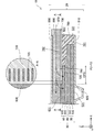
- the gas permeable structure 735 is a structure that forms a slit (slit).
- the gas permeable structure 735 forms a plurality of slits closed at both ends.
- the gas permeable structure 735 may form a plurality of slits that are open at one end and are arranged in a comb shape.
- the gas permeable structures 715, 725, and 745 are the same structure as the gas permeable structure 735.
- the fuel gas can be supplied to the portion of the anode electrode 50 where the plate-like members 710 and 720 are laminated through the gas permeable structures 715 and 725 and the plate-like shape of the cathode electrode 60.
- Oxidizing gas can be supplied to the portion where the members 730 and 740 are stacked through the gas permeable structures 735 and 745. Therefore, the thin film of the electrolyte membrane 40 due to insufficient supply of the reaction gas by the plate-like members 710, 720, 730, and 740 can be prevented. As a result, the durability of the fuel cell 10 can be improved.
- the gas permeable structures 715, 725, 735, and 745 are slits, the gas permeable structures 715, 725, 735, and 745 can be easily realized.
- the plate-like members 710 and 720 prevent a decrease in the flow rate of the fuel gas caused by the blocking of the anode flow path 820 by the sealing member 780, the electrolyte membrane caused by the insufficient supply of fuel gas by the plate-like members 710 and 720 Forty thin films can be prevented by the gas permeable structures 715 and 725.
- the plate-like members 730 and 740 prevent a decrease in the flow rate of the oxidizing gas due to the blocking of the cathode channel 870 by the sealing member 780, the electrolyte membrane caused by the insufficient supply of the oxidizing gas by the plate-like members 730 and 740 40 film thinning can be prevented by the gas permeable structures 735 and 745.
- the durability of the fuel cell 10 having an electrode structure including the anode catalyst layer 510, the anode diffusion layer 530, the cathode catalyst layer 610, and the cathode diffusion layer 630 can be improved. Further, the durability of the fuel cell 10 in which the plate-like members 710, 720, 730, and 740 protrude inward from the peripheral edge 637 of the sealing member 780 can be improved.
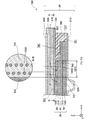
- FIG. 3 is explanatory drawing which shows the cross-sectional structure of the fuel cell 10B of 2nd Embodiment.
- the lower part of FIG. 3 shows a cross-sectional configuration of the fuel cell 10B as viewed from an arrow F3-F3 corresponding to the arrow F2-F2 in FIG.
- the upper part of FIG. 2 shows a cross-sectional configuration of the fuel cell 10B as viewed from the arrow BB in FIG.
- the fuel cell 10B of the second embodiment is the same as the fuel cell 10 of the first embodiment except that the gas permeable structure of the plate member is different.
- the plate-like member 730 has a gas permeable structure 735B in the part CP3 instead of the gas permeable structure 735.
- the gas permeable structure 735B is a structure that forms a through hole.
- the gas permeable structure 735B forms a plurality of through holes arranged alternately in two rows.
- a plurality of through holes arranged in one row may be formed, a plurality of through holes arranged in three or more rows may be formed, or a plurality of through holes arranged irregularly may be formed. May be.
- the plate-like members 710, 720, 740 also have the same structure as the gas permeable structure 735B, similarly to the plate-like member 730.
- the durability of the fuel cell 10B can be improved as in the first embodiment.
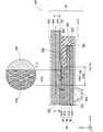
- FIG. 4 is explanatory drawing which shows the cross-sectional structure of 10 C of fuel cells of 3rd Embodiment.
- the lower part of FIG. 4 shows a cross-sectional configuration of the fuel cell 10C as viewed from an arrow F4-F4 corresponding to the arrow F2-F2 in FIG.
- the upper part of FIG. 4 shows a cross-sectional configuration of the fuel cell 10C as viewed from the direction CC in FIG.
- the fuel cell 10C of the third embodiment is the same as the fuel cell 10 of the first embodiment, except that the gas permeable structure of the plate member is different.
- the plate-like member 730 has a gas permeable structure 735C in the part CP3 instead of the gas permeable structure 735.
- the gas permeable structure 735C is a structure forming a mesh (mesh).
- the plate-like members 710, 720, 740 also have the same structure as the gas permeation structure 735C, like the plate-like member 730.
- the durability of the fuel cell 10C can be improved as in the first embodiment.
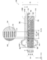
- FIG. 5 is explanatory drawing which shows the cross-sectional structure of fuel cell 10D of 4th Embodiment.
- the lower part of FIG. 5 shows a cross-sectional configuration of the fuel cell 10D viewed from an arrow F5-F5 corresponding to the arrow F2-F2 in FIG.
- the upper part of FIG. 5 shows a cross-sectional configuration of the fuel cell 10D viewed from the arrow DD in FIG.
- the fuel cell 10D of the fourth embodiment is the same as the fuel cell 10 of the first embodiment, except that the gas permeable structure of the plate member is different.
- the plate-like member 730 has a gas permeable structure 735D in the part CP3 instead of the gas permeable structure 735.
- the gas permeable structure 735D is a porous body that forms continuous pores.
- the gas permeable structure 735D is an expanded metal.
- the gas permeable structure 735D may be a foamed sintered body.
- the plate-like members 710, 720, and 740 also have the same structure as the gas permeable structure 735D, similarly to the plate-like member 730.
- the durability of the fuel cell 10D can be improved as in the first embodiment.
- FIG. 6 is an explanatory diagram showing a cross-sectional configuration of a fuel cell 10E according to a fifth embodiment.
- the lower part of FIG. 6 shows a cross-sectional configuration of the fuel cell 10E as viewed from an arrow F6-F6 corresponding to the arrow F2-F2 in FIG.
- the upper part of FIG. 6 shows a cross-sectional configuration of the fuel cell 10E as viewed from the direction of arrows EE in FIG.
- the fuel cell 10E of the fifth embodiment is the same as the fuel cell 10 of the first embodiment except that the configuration on the anode side is different.
- the fuel cell 10E includes a cathode isolation member 860E instead of the cathode isolation member 860 and the porous body 880.
- the cathode isolation member 860E is also a channel forming member that forms a cathode channel 870E for flowing an oxidizing gas to the cathode electrode 60, and is stacked on the cathode electrode 60, except for the point that it is stacked on the cathode electrode 60.
- the cathode isolation member 860E has the same shape as the anode isolation member 810.
- the durability of the fuel cell 10E can be improved as in the first embodiment.
- Embodiments The present invention is not limited to the above-described embodiments, examples, and modifications, and can be realized with various configurations without departing from the spirit thereof.
- the technical features in the embodiments, examples, and modifications corresponding to the technical features in each embodiment described in the summary section of the invention are to solve some or all of the above-described problems, or In order to achieve part or all of the above-described effects, replacement or combination can be performed as appropriate. Further, if the technical feature is not described as essential in the present specification, it can be deleted as appropriate.
- the fuel cell 10 may be provided with at least one plate-like member among the plate-like members 710, 720, 730, and 740. You may apply the above-mentioned gas permeable structure to the plate-shaped member laminated
- the structure for forming the anode flow path described above may be applied to the cathode flow path, and the structure for forming the cathode flow path described above may be applied to the anode flow path.
- the peripheral edge 637 of the cathode electrode 60 may be located outside the peripheral edge 537 of the anode electrode 50.
- the peripheral edge 637 of the cathode electrode 60 may be the same size as the peripheral edge 537 of the anode electrode 50.
- the material of the anode isolation member 810 and the cathode isolation member 860 may be at least one of stainless steel, titanium, a titanium alloy, and conductive ceramics.
- the anode isolation member 810 and the cathode isolation member 860 are not limited to being configured separately from each other, and in two adjacent cells 20, the anode isolation member 810 of one cell 20 and the cathode isolation member 860 of the other cell 20. May be configured integrally.
- SYMBOLS 10 DESCRIPTION OF SYMBOLS 10 ... Fuel cell 10B ... Fuel cell 10C ... Fuel cell 10D ... Fuel cell 10E ... Fuel cell 20 ... Cell 21 ... Fuel gas inlet 22 ... Fuel gas outlet 23 ... Oxidant gas inlet 24 ... Oxidant gas outlet 25 ... Cooling Water inlet 26 ... Cooling water outlet 30 ... Membrane electrode assembly (MEA) DESCRIPTION OF SYMBOLS 40 ... Electrolyte membrane 50 ... Anode electrode 60 ... Cathode electrode 510 ... Anode catalyst layer 530 ... Anode diffusion layer 531 ... Surface 537 ... Perimeter 610 ... Cathode catalyst layer 630 ... Cathode diffusion layer 631 ...
- MEA Membrane electrode assembly
Landscapes
- Chemical & Material Sciences (AREA)
- Chemical Kinetics & Catalysis (AREA)
- Electrochemistry (AREA)
- General Chemical & Material Sciences (AREA)
- Life Sciences & Earth Sciences (AREA)
- Engineering & Computer Science (AREA)
- Manufacturing & Machinery (AREA)
- Sustainable Development (AREA)
- Sustainable Energy (AREA)
- Fuel Cell (AREA)
Abstract
Description
図1は、燃料電池10の構成を示す説明図である。図2は、燃料電池10の断面構成を示す説明図である。図2の下段には、図1の矢視F2-F2から見た燃料電池10の断面構成が図示されている。図2の上段には、図2の矢視A-Aから見た燃料電池10の断面構成が図示されている。
図3は、第2実施形態の燃料電池10Bの断面構成を示す説明図である。図3の下段には、図1の矢視F2-F2に相当する矢視F3-F3から見た燃料電池10Bの断面構成が図示されている。図2の上段には、図3の矢視B-Bから見た燃料電池10Bの断面構成が図示されている。
図4は、第3実施形態の燃料電池10Cの断面構成を示す説明図である。図4の下段には、図1の矢視F2-F2に相当する矢視F4-F4から見た燃料電池10Cの断面構成が図示されている。図4の上段には、図4の矢視C-Cから見た燃料電池10Cの断面構成が図示されている。
図5は、第4実施形態の燃料電池10Dの断面構成を示す説明図である。図5の下段には、図1の矢視F2-F2に相当する矢視F5-F5から見た燃料電池10Dの断面構成が図示されている。図5の上段には、図5の矢視D-Dから見た燃料電池10Dの断面構成が図示されている。
図6は、第5実施形態の燃料電池10Eの断面構成を示す説明図である。図6の下段には、図1の矢視F2-F2に相当する矢視F6-F6から見た燃料電池10Eの断面構成が図示されている。図6の上段には、図6の矢視E-Eから見た燃料電池10Eの断面構成が図示されている。
本発明は、上述の実施形態や実施例、変形例に限られるものではなく、その趣旨を逸脱しない範囲において種々の構成で実現することができる。例えば、発明の概要の欄に記載した各形態中の技術的特徴に対応する実施形態、実施例、変形例中の技術的特徴は、上述の課題の一部または全部を解決するために、あるいは、上述の効果の一部または全部を達成するために、適宜、差し替えや、組み合わせを行うことが可能である。また、その技術的特徴が本明細書中に必須なものとして説明されていなければ、適宜、削除することが可能である。
10B…燃料電池
10C…燃料電池
10D…燃料電池
10E…燃料電池
20…セル
21…燃料ガス導入口
22…燃料ガス導出口
23…酸化ガス導入口
24…酸化ガス導出口
25…冷却水導入口
26…冷却水導出口
30…膜電極接合体(MEA)
40…電解質膜
50…アノード電極
60…カソード電極
510…アノード触媒層
530…アノード拡散層
531…表面
537…周縁
610…カソード触媒層
630…カソード拡散層
631…表面
637…周縁
710…板状部材
715…ガス透過構造
720…板状部材
725…ガス透過構造
730…板状部材
735…ガス透過構造
735B…ガス透過構造
735C…ガス透過構造
735D…ガス透過構造
740…板状部材
745…ガス透過構造
780…密封部材
781…表面
782…表面
788…端部
810…アノード隔離部材
820…アノード流路
860…カソード隔離部材
860E…カソード隔離部材
870…カソード流路
870E…カソード流路
880…多孔体
Claims (9)
- 燃料電池であって
アノード電極とカソード電極との間に電解質膜を接合した膜電極接合体と、
前記アノード電極と前記カソード電極とのうちの一方の電極に隣接する流路であって前記一方の電極に反応ガスを流す流路を、形成する流路形成部材と、
前記反応ガスを遮断する材質から成り、前記一方の電極における前記流路側の表面の一部に積層され、前記流路に隣接する板状部材と
を備え、
前記板状部材は、前記反応ガスを透過させる構造であるガス透過構造を、前記板状部材を前記一方の電極に対して積層する方向に前記アノード電極と前記カソード電極とが存在する部位に有する、燃料電池。 - 前記アノード電極と前記カソード電極とのうち第1の電極の周縁は、前記アノード電極と前記カソード電極とのうち前記第1の電極とは異なる第2の電極の周縁よりも内側に位置する、請求項1に記載の燃料電池。
- さらに、前記膜電極接合体および前記板状部材と一体的に成形され、前記膜電極接合体の外周を密封する密封部材を備える請求項1または請求項2に記載の燃料電池。
- 前記流路形成部材は、前記流路として連続気孔を形成し、前記一方の電極および前記板状部材に隣接する多孔体を含む、請求項1から請求項3までのいずれか一項に記載の燃料電池。
- 前記ガス透過構造は、スリットと、貫通孔と、メッシュと、連続気孔との少なくとも1つを形成する構造である、請求項1から請求項4までのいずれか一項に記載の燃料電池。
- 請求項1から請求項5までのいずれか一項に記載の燃料電池であって、さらに、
前記流路に前記反応ガスを導入する導入口と、
前記流路から前記反応ガスを導出する導出口と
を備え、
前記板状部材は、前記流路のうち前記導入口に繋がる領域と、前記流路のうち前記導出口に繋がる領域との少なくとも一方の領域に隣接する、燃料電池。 - 請求項1から請求項6までのいずれか一項に記載の燃料電池であって、
前記アノード電極は、
前記電解質膜に積層されたアノード触媒層と、
前記アノード触媒層に積層されたアノード拡散層と
を含み、
前記カソード電極は、
前記電解質膜に積層されたカソード触媒層と、
前記カソード触媒層に積層されたカソード拡散層と
を含む、燃料電池。 - 前記板状部材は、前記膜電極接合体の外周を密封する密封部材における内側の端部よりも内側へと突出した部材である、請求項1から請求項7までのいずれか一項に記載の燃料電池。
- 燃料電池であって、
アノード電極とカソード電極との間に電解質膜を接合した膜電極接合体と、
前記膜電極接合体と一体的に成形され、前記膜電極接合体の外周を密封する密封部材と、
前記アノード電極に積層され、前記アノード電極に燃料ガスを流すアノード流路を形成するとともに、前記膜電極接合体のアノード側を外部から隔離するアノード隔離部材と、
前記アノード流路に前記燃料ガスを導入する第1の導入口と、
前記アノード流路から前記燃料ガスを導出する第1の導出口と、
前記カソード電極に積層され、前記カソード電極に酸化ガスを流すカソード流路として連続気孔を形成する多孔体と、
前記多孔体に積層され、前記膜電極接合体のカソード側を外部から隔離するカソード隔離部材と、
前記カソード流路に前記酸化ガスを導入する第2の導入口と、
前記カソード流路から前記酸化ガスを導出する第2の導出口と、
前記燃料ガスを遮断する材質から成り、前記密封部材における前記アノード流路側の表面の一部から、前記アノード電極における前記アノード流路側の表面の一部にわたって積層され、前記アノード流路のうち前記第1の導入口に繋がる領域に隣接する第1の板状部材と、
前記燃料ガスを遮断する材質から成り、前記密封部材における前記アノード流路側の表面の一部から、前記アノード電極における前記アノード流路側の表面の一部にわたって積層され、前記アノード流路のうち前記第1の導出口に繋がる領域に隣接する第2の板状部材と、
前記酸化ガスを遮断する材質から成り、前記密封部材における前記カソード流路側の表面の一部から、前記カソード電極における前記カソード流路側の表面の一部にわたって積層され、前記カソード流路のうち前記第2の導入口に繋がる領域に隣接する第3の板状部材と、
前記酸化ガスを遮断する材質から成り、前記密封部材における前記カソード流路側の表面の一部から、前記カソード電極における前記カソード流路側の表面の一部にわたって積層され、前記カソード流路のうち前記第2の導出口に繋がる領域に隣接する第4の板状部材と
を備え、
前記第1および第2の板状部材は、前記燃料ガスを透過させる構造を、前記第1および第2の板状部材を前記アノード電極に対して積層する方向に前記アノード電極と前記カソード電極とが存在する部位に有し、
前記第3および第4の板状部材は、前記酸化ガスを透過させる構造を、前記第3および第4の板状部材を前記アノード電極に対して積層する方向に前記アノード電極と前記カソード電極とが存在する部位に有する、燃料電池。
Priority Applications (6)
| Application Number | Priority Date | Filing Date | Title |
|---|---|---|---|
| CA2894627A CA2894627C (en) | 2013-03-22 | 2013-03-22 | Fuel cell with plate-like member |
| PCT/JP2013/001953 WO2014147665A1 (ja) | 2013-03-22 | 2013-03-22 | 燃料電池 |
| US14/778,249 US9748587B2 (en) | 2013-03-22 | 2013-03-22 | Fuel cell |
| DE112013006854.0T DE112013006854B4 (de) | 2013-03-22 | 2013-03-22 | Brennstoffzelle mit verbesserter Haltbarkeit |
| CN201380074943.2A CN105051958B (zh) | 2013-03-22 | 2013-03-22 | 燃料电池 |
| JP2014533714A JP5713151B2 (ja) | 2013-03-22 | 2013-03-22 | 燃料電池 |
Applications Claiming Priority (1)
| Application Number | Priority Date | Filing Date | Title |
|---|---|---|---|
| PCT/JP2013/001953 WO2014147665A1 (ja) | 2013-03-22 | 2013-03-22 | 燃料電池 |
Publications (1)
| Publication Number | Publication Date |
|---|---|
| WO2014147665A1 true WO2014147665A1 (ja) | 2014-09-25 |
Family
ID=51579408
Family Applications (1)
| Application Number | Title | Priority Date | Filing Date |
|---|---|---|---|
| PCT/JP2013/001953 Ceased WO2014147665A1 (ja) | 2013-03-22 | 2013-03-22 | 燃料電池 |
Country Status (6)
| Country | Link |
|---|---|
| US (1) | US9748587B2 (ja) |
| JP (1) | JP5713151B2 (ja) |
| CN (1) | CN105051958B (ja) |
| CA (1) | CA2894627C (ja) |
| DE (1) | DE112013006854B4 (ja) |
| WO (1) | WO2014147665A1 (ja) |
Families Citing this family (2)
| Publication number | Priority date | Publication date | Assignee | Title |
|---|---|---|---|---|
| KR101766098B1 (ko) * | 2015-12-30 | 2017-08-08 | 현대자동차주식회사 | 연료전지의 다공 패널 |
| US11387469B2 (en) * | 2018-01-17 | 2022-07-12 | Nuvera Fuel Cells, LLC | Electrochemical cells with improved fluid flow design |
Citations (4)
| Publication number | Priority date | Publication date | Assignee | Title |
|---|---|---|---|---|
| JP2007048472A (ja) * | 2005-08-05 | 2007-02-22 | Toyota Motor Corp | 燃料電池 |
| JP2012123949A (ja) * | 2010-12-06 | 2012-06-28 | Toyota Motor Corp | 燃料電池セル |
| JP2012226979A (ja) * | 2011-04-20 | 2012-11-15 | Toyota Motor Corp | 燃料電池 |
| JP2013054872A (ja) * | 2011-09-02 | 2013-03-21 | Toyota Motor Corp | 燃料電池 |
Family Cites Families (9)
| Publication number | Priority date | Publication date | Assignee | Title |
|---|---|---|---|---|
| CN1536698B (zh) * | 2003-04-02 | 2010-12-15 | 松下电器产业株式会社 | 燃料电池用电解质膜结构、mea结构及燃料电池 |
| JP4392287B2 (ja) | 2004-05-26 | 2009-12-24 | 本田技研工業株式会社 | 固体高分子型燃料電池 |
| JP5194346B2 (ja) | 2005-08-31 | 2013-05-08 | 日産自動車株式会社 | 電解質膜−電極接合体 |
| JP5087863B2 (ja) * | 2006-06-09 | 2012-12-05 | トヨタ自動車株式会社 | 燃料電池 |
| JP2010027332A (ja) | 2008-07-17 | 2010-02-04 | Honda Motor Co Ltd | 燃料電池 |
| CN102687322B (zh) * | 2009-12-01 | 2014-10-29 | 丰田自动车株式会社 | 燃料电池 |
| JP2012033325A (ja) | 2010-07-29 | 2012-02-16 | Toyota Motor Corp | 燃料電池 |
| JP2012069445A (ja) | 2010-09-27 | 2012-04-05 | Toyota Motor Corp | 燃料電池 |
| JP5348273B2 (ja) | 2012-03-28 | 2013-11-20 | トヨタ自動車株式会社 | 燃料電池シーリングプレートの取り出し方法および燃料電池シーリングプレート |
-
2013
- 2013-03-22 DE DE112013006854.0T patent/DE112013006854B4/de active Active
- 2013-03-22 JP JP2014533714A patent/JP5713151B2/ja active Active
- 2013-03-22 CN CN201380074943.2A patent/CN105051958B/zh active Active
- 2013-03-22 US US14/778,249 patent/US9748587B2/en active Active
- 2013-03-22 CA CA2894627A patent/CA2894627C/en active Active
- 2013-03-22 WO PCT/JP2013/001953 patent/WO2014147665A1/ja not_active Ceased
Patent Citations (4)
| Publication number | Priority date | Publication date | Assignee | Title |
|---|---|---|---|---|
| JP2007048472A (ja) * | 2005-08-05 | 2007-02-22 | Toyota Motor Corp | 燃料電池 |
| JP2012123949A (ja) * | 2010-12-06 | 2012-06-28 | Toyota Motor Corp | 燃料電池セル |
| JP2012226979A (ja) * | 2011-04-20 | 2012-11-15 | Toyota Motor Corp | 燃料電池 |
| JP2013054872A (ja) * | 2011-09-02 | 2013-03-21 | Toyota Motor Corp | 燃料電池 |
Also Published As
| Publication number | Publication date |
|---|---|
| US9748587B2 (en) | 2017-08-29 |
| JPWO2014147665A1 (ja) | 2017-02-16 |
| US20160072139A1 (en) | 2016-03-10 |
| CN105051958B (zh) | 2017-05-10 |
| DE112013006854T5 (de) | 2015-12-03 |
| DE112013006854B4 (de) | 2018-12-06 |
| CA2894627C (en) | 2017-09-26 |
| CA2894627A1 (en) | 2014-09-25 |
| CN105051958A (zh) | 2015-11-11 |
| JP5713151B2 (ja) | 2015-05-07 |
Similar Documents
| Publication | Publication Date | Title |
|---|---|---|
| JP5125275B2 (ja) | 燃料電池および燃料電池搭載車両 | |
| CN103053057B (zh) | 燃料电池 | |
| JP5223849B2 (ja) | 燃料電池 | |
| KR100953273B1 (ko) | 연료전지용 금속 분리판 및 이를 구비하는 연료전지 스택 | |
| JP2012146524A (ja) | 燃料電池 | |
| JP5321086B2 (ja) | 燃料電池 | |
| JP2020502759A (ja) | 燃料電池のためのバイポーラプレートおよび燃料電池 | |
| KR20150017402A (ko) | 냉각 성능이 우수한 연료전지 스택 | |
| JP5713151B2 (ja) | 燃料電池 | |
| JP2018181661A (ja) | 燃料電池セル | |
| JP2022082001A (ja) | 燃料電池 | |
| JP5101866B2 (ja) | 燃料電池 | |
| JP5653867B2 (ja) | 燃料電池 | |
| JP6170868B2 (ja) | 燃料電池 | |
| JP6104103B2 (ja) | 燃料電池 | |
| JP7205381B2 (ja) | 燃料電池の製造方法 | |
| JP5830403B2 (ja) | 燃料電池用電解質膜・電極構造体 | |
| JP2007018742A (ja) | 燃料電池 | |
| KR101819797B1 (ko) | 연료 전지 셀 | |
| JP2013114899A (ja) | 燃料電池用スタック | |
| JP5223203B2 (ja) | 燃料電池 | |
| JP2008123750A (ja) | 燃料電池 | |
| JP2016048627A (ja) | 燃料電池 | |
| JP2017147141A (ja) | 燃料電池スタック | |
| JP2008277041A (ja) | 燃料電池および燃料電池用ガスセパレータ |
Legal Events
| Date | Code | Title | Description |
|---|---|---|---|
| WWE | Wipo information: entry into national phase |
Ref document number: 201380074943.2 Country of ref document: CN |
|
| ENP | Entry into the national phase |
Ref document number: 2014533714 Country of ref document: JP Kind code of ref document: A |
|
| 121 | Ep: the epo has been informed by wipo that ep was designated in this application |
Ref document number: 13878555 Country of ref document: EP Kind code of ref document: A1 |
|
| ENP | Entry into the national phase |
Ref document number: 2894627 Country of ref document: CA |
|
| WWE | Wipo information: entry into national phase |
Ref document number: 14778249 Country of ref document: US |
|
| WWE | Wipo information: entry into national phase |
Ref document number: 1120130068540 Country of ref document: DE Ref document number: 112013006854 Country of ref document: DE |
|
| 122 | Ep: pct application non-entry in european phase |
Ref document number: 13878555 Country of ref document: EP Kind code of ref document: A1 |