WO2014142265A1 - Dispositif de joint mécanique - Google Patents
Dispositif de joint mécanique Download PDFInfo
- Publication number
- WO2014142265A1 WO2014142265A1 PCT/JP2014/056763 JP2014056763W WO2014142265A1 WO 2014142265 A1 WO2014142265 A1 WO 2014142265A1 JP 2014056763 W JP2014056763 W JP 2014056763W WO 2014142265 A1 WO2014142265 A1 WO 2014142265A1
- Authority
- WO
- WIPO (PCT)
- Prior art keywords
- seal
- ring
- sealing
- seal ring
- bellows
- Prior art date
Links
Images


Classifications
-
- F—MECHANICAL ENGINEERING; LIGHTING; HEATING; WEAPONS; BLASTING
- F16—ENGINEERING ELEMENTS AND UNITS; GENERAL MEASURES FOR PRODUCING AND MAINTAINING EFFECTIVE FUNCTIONING OF MACHINES OR INSTALLATIONS; THERMAL INSULATION IN GENERAL
- F16J—PISTONS; CYLINDERS; SEALINGS
- F16J15/00—Sealings
- F16J15/16—Sealings between relatively-moving surfaces
- F16J15/34—Sealings between relatively-moving surfaces with slip-ring pressed against a more or less radial face on one member
- F16J15/36—Sealings between relatively-moving surfaces with slip-ring pressed against a more or less radial face on one member connected by a diaphragm or bellow to the other member
-
- F—MECHANICAL ENGINEERING; LIGHTING; HEATING; WEAPONS; BLASTING
- F16—ENGINEERING ELEMENTS AND UNITS; GENERAL MEASURES FOR PRODUCING AND MAINTAINING EFFECTIVE FUNCTIONING OF MACHINES OR INSTALLATIONS; THERMAL INSULATION IN GENERAL
- F16J—PISTONS; CYLINDERS; SEALINGS
- F16J15/00—Sealings
- F16J15/16—Sealings between relatively-moving surfaces
- F16J15/34—Sealings between relatively-moving surfaces with slip-ring pressed against a more or less radial face on one member
- F16J15/3404—Sealings between relatively-moving surfaces with slip-ring pressed against a more or less radial face on one member and characterised by parts or details relating to lubrication, cooling or venting of the seal
- F16J15/3408—Sealings between relatively-moving surfaces with slip-ring pressed against a more or less radial face on one member and characterised by parts or details relating to lubrication, cooling or venting of the seal at least one ring having an uneven slipping surface
- F16J15/3412—Sealings between relatively-moving surfaces with slip-ring pressed against a more or less radial face on one member and characterised by parts or details relating to lubrication, cooling or venting of the seal at least one ring having an uneven slipping surface with cavities
- F16J15/342—Sealings between relatively-moving surfaces with slip-ring pressed against a more or less radial face on one member and characterised by parts or details relating to lubrication, cooling or venting of the seal at least one ring having an uneven slipping surface with cavities with means for feeding fluid directly to the face
-
- F—MECHANICAL ENGINEERING; LIGHTING; HEATING; WEAPONS; BLASTING
- F16—ENGINEERING ELEMENTS AND UNITS; GENERAL MEASURES FOR PRODUCING AND MAINTAINING EFFECTIVE FUNCTIONING OF MACHINES OR INSTALLATIONS; THERMAL INSULATION IN GENERAL
- F16J—PISTONS; CYLINDERS; SEALINGS
- F16J15/00—Sealings
- F16J15/16—Sealings between relatively-moving surfaces
- F16J15/34—Sealings between relatively-moving surfaces with slip-ring pressed against a more or less radial face on one member
- F16J15/3404—Sealings between relatively-moving surfaces with slip-ring pressed against a more or less radial face on one member and characterised by parts or details relating to lubrication, cooling or venting of the seal
- F16J15/3408—Sealings between relatively-moving surfaces with slip-ring pressed against a more or less radial face on one member and characterised by parts or details relating to lubrication, cooling or venting of the seal at least one ring having an uneven slipping surface
-
- F—MECHANICAL ENGINEERING; LIGHTING; HEATING; WEAPONS; BLASTING
- F16—ENGINEERING ELEMENTS AND UNITS; GENERAL MEASURES FOR PRODUCING AND MAINTAINING EFFECTIVE FUNCTIONING OF MACHINES OR INSTALLATIONS; THERMAL INSULATION IN GENERAL
- F16J—PISTONS; CYLINDERS; SEALINGS
- F16J15/00—Sealings
- F16J15/16—Sealings between relatively-moving surfaces
- F16J15/34—Sealings between relatively-moving surfaces with slip-ring pressed against a more or less radial face on one member
- F16J15/3436—Pressing means
- F16J15/3448—Pressing means the pressing force resulting from fluid pressure
-
- F—MECHANICAL ENGINEERING; LIGHTING; HEATING; WEAPONS; BLASTING
- F16—ENGINEERING ELEMENTS AND UNITS; GENERAL MEASURES FOR PRODUCING AND MAINTAINING EFFECTIVE FUNCTIONING OF MACHINES OR INSTALLATIONS; THERMAL INSULATION IN GENERAL
- F16J—PISTONS; CYLINDERS; SEALINGS
- F16J15/00—Sealings
- F16J15/16—Sealings between relatively-moving surfaces
- F16J15/34—Sealings between relatively-moving surfaces with slip-ring pressed against a more or less radial face on one member
- F16J15/36—Sealings between relatively-moving surfaces with slip-ring pressed against a more or less radial face on one member connected by a diaphragm or bellow to the other member
- F16J15/363—Sealings between relatively-moving surfaces with slip-ring pressed against a more or less radial face on one member connected by a diaphragm or bellow to the other member the diaphragm or bellow being made of metal
-
- F—MECHANICAL ENGINEERING; LIGHTING; HEATING; WEAPONS; BLASTING
- F16—ENGINEERING ELEMENTS AND UNITS; GENERAL MEASURES FOR PRODUCING AND MAINTAINING EFFECTIVE FUNCTIONING OF MACHINES OR INSTALLATIONS; THERMAL INSULATION IN GENERAL
- F16J—PISTONS; CYLINDERS; SEALINGS
- F16J15/00—Sealings
- F16J15/16—Sealings between relatively-moving surfaces
- F16J15/34—Sealings between relatively-moving surfaces with slip-ring pressed against a more or less radial face on one member
- F16J15/3404—Sealings between relatively-moving surfaces with slip-ring pressed against a more or less radial face on one member and characterised by parts or details relating to lubrication, cooling or venting of the seal
- F16J15/3408—Sealings between relatively-moving surfaces with slip-ring pressed against a more or less radial face on one member and characterised by parts or details relating to lubrication, cooling or venting of the seal at least one ring having an uneven slipping surface
- F16J15/3412—Sealings between relatively-moving surfaces with slip-ring pressed against a more or less radial face on one member and characterised by parts or details relating to lubrication, cooling or venting of the seal at least one ring having an uneven slipping surface with cavities
- F16J15/3416—Sealings between relatively-moving surfaces with slip-ring pressed against a more or less radial face on one member and characterised by parts or details relating to lubrication, cooling or venting of the seal at least one ring having an uneven slipping surface with cavities with at least one continuous groove
Definitions
- the present invention relates to a mechanical seal device.
- a static pressure type mechanical seal device that prevents leakage of a sealing fluid sealed inside the machine to the outside of the machine.
- this static pressure type mechanical seal device by supplying a purge gas having a pressure higher than that of the sealing fluid to the sealing surface, the purge gas is leaked to the inside and outside of the machine to prevent the sealing fluid from leaking outside the machine. Yes.
- the balance between the in-machine pressure and the purge gas pressure is lost due to the pressure fluctuation inside the machine, and it is sometimes difficult to properly maintain the gap between the sliding surfaces.
- the gap between the sliding surfaces opens more than necessary, and the sealing fluid may leak to the outside of the machine.
- the in-machine pressure becomes smaller than a predetermined pressure, the sliding surface comes into contact with each other, and the sliding surface may be damaged.
- Patent Document 1 In order to solve such a problem, for example, a mechanical seal device shown in Patent Document 1 has been proposed.
- a back pressure introduction path is formed that communicates the in-machine region and the back region of the fixing sealing ring.
- the present invention has been made in view of such problems, and an object thereof is to provide a mechanical seal device capable of suitably sealing a sealing fluid.
- a mechanical seal device comprises: A mechanical seal device that seals a sealing fluid inside the device with a gap between the device body and the rotating shaft, A seal case attached to the apparatus body; A rotating seal ring attached to the rotating shaft; A stationary seal ring disposed axially opposite to the rotary seal ring; A bellows attached in an axially extendable manner between the fixing seal ring and the seal case;
- a static pressure fluid supply hole for supplying a static pressure fluid is formed in the static pressure fluid chamber on the inner peripheral surface side of the bellows
- In the fixing seal ring a communication hole for guiding the static pressure fluid in the static pressure fluid chamber to a seal surface between the fixing seal ring and the rotation seal ring is formed,
- the sealing fluid is arranged on the outer peripheral surface side of the bellows.
- the sealing performance is suitably exhibited even when sealing the sealing fluid containing the solid component. Can do.
- the pressure of the sealing fluid is applied to the outer peripheral surface of the bellows so that the bellows exerts a sealing function and imparts a pressing force.
- the configuration of can be omitted.
- the sealing ring for fixation can be smoothly moved in the axial direction, and a suitable sealing performance can be exhibited.
- the sealing ring for fixing attached to the bellows can absorb vibrations of the device and can exhibit suitable sealing performance. .
- the sealing fluid is arranged on the outer peripheral surface side of the bellows, the design freedom on the inner peripheral surface side of the bellows is greatly improved. That is, even when sealing a corrosive sealing fluid or a sealing fluid containing a solid component, the inner peripheral surface of the bellows does not come into contact with the sealing fluid, so the material of the member disposed on the inner peripheral side of the bellows is free. Can be selected.
- the bellows is disposed between the seal case and the fixing sealing ring on the inner peripheral surface side of the bellows, and holds the fixing sealing ring so as to be movable in the axial direction.
- the mechanical seal device further includes a seal member that seals from the side space.
- the sealing fluid does not contact the seal member. For this reason, the choice of the material of a sealing member spreads, and also the possibility of deterioration of the sealing member by the sealing fluid contacting is also eliminated.
- annular groove continuous with the communication hole is formed in the sealing ring for fixing. Since the annular groove continuing to the communication hole guides the static pressure fluid to the entire seal surface between the fixing seal ring and the rotation seal ring, the static pressure can be suitably applied to the entire seal surface.
- the outer diameter of the annular groove is substantially equal to the pressure acting diameter of the bellows.
- the mechanical seal device further includes an elastic member that is disposed closer to the atmosphere than the seal member and presses the fixing seal ring toward the rotation seal ring.
- the elastic member By disposing the elastic member on the atmosphere side of the seal member, the elastic member does not contact the sealing fluid and the static pressure fluid.
- the choice of the material of the elastic member is widened, and the possibility of deterioration of the elastic member due to contact between the sealing fluid and the static pressure fluid is also eliminated.
- the inner diameter of the annular groove is substantially equal to the contact diameter of the sealing member with respect to the fixing sealing ring.
- An elastic member that presses the fixing sealing ring toward the rotating sealing ring may be disposed inside the static pressure fluid chamber.
- the pressure of the static pressure fluid in the static pressure fluid pressure chamber also acts on the back surface of the fixing seal ring pressed by the elastic member. Therefore, it becomes possible to increase the pressing force of the stationary seal ring against the rotation seal ring by the hydrostatic fluid.
- Such a configuration is particularly effective when there is a demand to increase the pressing force of the fixing seal ring against the rotation seal ring.
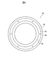
- a dynamic pressure generating groove is formed on the sealing surface of the rotary sealing ring.
- the dynamic pressure generating groove generates a dynamic pressure when the rotation sealing ring rotates, and can guide the static pressure fluid to the entire seal surface, and can preferably apply the static pressure to the entire seal surface.
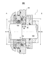
- FIG. 1 is a cross-sectional view of a mechanical seal device according to an embodiment of the present invention.
- FIG. 2 is a diagram for explaining a main part of the cross-sectional view shown in FIG.
- FIG. 3 is a front view of the rotary seal ring shown in FIGS. 1 and 2.
- FIG. 4 is a front view of the fixing sealing ring shown in FIGS. 1 and 2.
- FIG. 5 is a half sectional view of a mechanical seal device according to another embodiment of the present invention.
- a mechanical seal device 1 according to the present embodiment is a seal device mounted on a general industrial stirrer, a blower, a compressor, or the like, and is particularly used for manufacturing foods, medical products, and chemical substances. Is done.
- the mechanical seal device 1 is configured as an inside type in which a sealing fluid is disposed radially outward with respect to the sealing surface, and a gap between the rotating shaft 100 and the stuffing box 80. Seal the sealing fluid on the B side in the machine.
- the left side in the axial direction is the outside A and the right side in the axial direction is the inside B.
- a shaft hole 82 is formed in the stuffing box 80, and a rotating shaft 100 that is rotatably supported by a bearing (not shown) passes therethrough.
- a rotation sealing ring 60 is arranged on the inner side in the radial direction of the shaft hole 82.
- the rotary seal ring 60 is attached to the rotary shaft 100 in a state where the rotary seal ring 60 is positioned in the axial direction by the spacer 75.
- the spacer 75 is disposed between the radial stepped portion 102 of the rotating shaft 100 and the rotating seal ring 60 and performs axial positioning of the rotating seal ring 60.
- the spacer 75 is made of a material having excellent strength such as SUS or engineering plastic.
- Fringer 70 and sleeve 76 are disposed on the side B in the axial direction of the sealing ring 60 for rotation.
- the sleeve 76 fixes the rotary seal ring 60 in the axial direction via the flinger 70.
- the flinger 70 is disposed between the sleeve 76 and the rotation sealing ring 60, and the solid component of the sealing fluid from the inside B of the machine between the shaft hole 82 of the stuffing box 80 and the outer peripheral surface of the rotation sealing ring 60. Prevents intrusion. That is, a cylindrical portion 71 that extends toward the outer side A in the axial direction is formed on the outer peripheral side of the fringer 70, and the cylindrical portion 71 has a protruding portion 86 that protrudes from the stuffing box 80 toward the B side in the axial direction. Covering. Further, the flinger 70 rotates together with the rotating shaft 100 to induce the sealing fluid and the solid component contained therein to the outside in the radial direction by centrifugal force. Therefore, the solid component of the sealing fluid is prevented from entering between the shaft hole 82 of the stuffing box 80 and the outer peripheral surface of the rotation sealing ring 60.
- the inner peripheral surface of the flinger 70 on the rotating seal ring 60 side is formed in a taper shape, and an O-ring 128 is disposed there.
- the O-ring 128 prevents the sealing fluid from leaking from between the rotary seal ring 60 and the rotary shaft 100.
- the rotary seal ring 60 has a seal surface 62 that faces the seal surface 55 of the fixed seal ring 50 on the outside A side.
- a dynamic pressure generating groove 64 is formed on the seal surface 62.
- the dynamic pressure generating groove 64 has a first groove 64A for forward rotation R1 and a second groove 64B for reverse rotation R2.
- the first grooves 64A and the second grooves 64B are arranged symmetrically in the radial direction, and a large number of first grooves 64A and second grooves 64B are paired and formed at equal intervals in the circumferential direction.
- the dynamic pressure generating groove 64 generates dynamic pressure when the rotation sealing ring 60 rotates together with the rotary shaft 100.
- a seal housing 10, an adapter 20, a seal case 30, a bellows 40, a fixing seal ring 50, and the like are arranged on the outer side A in the axial direction of the rotation seal ring 60.
- the seal housing 10 is attached to the stuffing box 80.
- the mounting groove (not shown) of the seal housing 10 is passed through an embedded bolt (not shown) provided on the outer surface 84 of the stuffing box 80 and tightened with a nut (not shown), whereby the seal housing 10 is stuffed.
- An O-ring 120 is disposed between the seal housing 10 and the stuffing box 80 to prevent leakage of the sealing fluid from between the seal housing 10 and the stuffing box 80.
- a mounting groove 16 is formed on the inner peripheral surface 12 of the seal housing 10 on the end surface 14 side on the side B in the axial direction, and an adapter 20 and a seal case 30 are attached to the mounting groove 16. Since the adapter 20 and the seal case 30 are accommodated in the mounting groove 16, the mechanical seal device 1 can be downsized in the axial direction and the radial direction.
- the adapter 20 attached to the seal housing 10 has a protruding portion 22 that extends toward the in-machine B side, and is assembled to the seal case 30 on the radially outer side of the protruding portion 22.
- the adapter 20 and the seal case 30 are fixed by a fastening member 130.
- a housing portion that houses the O-ring 122 (seal member) is configured between the tip of the protruding portion 22 and the step portion on the inner peripheral surface of the seal case 30.
- the adapter 20 and the seal case 30 may be integrally formed. Even if the adapter 20 is separate from the seal case 30, the adapter 20 is handled as a part of the seal case 30 in the present embodiment.
- the bellows 40 is attached to the step outer diameter end portion 32 on the side B in the axial direction of the seal case 30, and the other end of the bellows 40 is attached to the outer diameter end portion 51 of the fixing seal ring 50. Yes.
- the bellows 40 is disposed inside the shaft hole 82 of the stuffing box 80, and a sealing fluid is disposed on the outer peripheral surface side of the bellows 40.
- the bellows 40 can expand and contract in the axial direction and can also be deformed in the radial direction. For this reason, since the sealing ring 50 for fixation attached to the bellows 40 can absorb the vibration of an apparatus, etc., the mechanical seal apparatus 1 can exhibit suitable sealing performance. Further, since the bellows 40 is used as the seal element, the mechanical seal device 1 can be downsized in the axial direction and the radial direction as compared with the case where an O-ring or the like is used.
- a cylindrical portion 52 is formed on the inner peripheral side of the fixing seal ring 50 and extends on the inner peripheral side of the bellows 40 toward the outer side A in the axial direction.
- An O-ring 122 is disposed between the outer peripheral surface of the cylindrical portion 52 and the inner peripheral stepped portion of the seal case 30, and is statically placed between the O-ring 122, the seal case 30, the bellows 40, and the fixing seal ring 50.
- a pressurized fluid chamber C is formed. The O-ring 122 seals the static pressure fluid chamber C from the atmosphere side space corresponding to the outside A.
- the static pressure fluid chamber C is supplied with a purge gas (for example, nitrogen gas) as a static pressure fluid from the static pressure fluid supply hole 34.
- a purge gas for example, nitrogen gas
- the static pressure fluid supplied from the static pressure fluid supply hole 34 can be appropriately selected according to the intended use of the mechanical seal device 1.
- the static pressure fluid may be a liquid such as water.
- the O-ring 122 seals between the outer peripheral surface of the cylindrical portion 52 of the fixing seal ring 50 and the seal case 30 and holds the fixing seal ring 50 so as to be movable in the axial direction. Since only the sliding resistance of one O-ring 122 acts when the sealing ring 50 for fixing moves in the axial direction, the sealing ring 50 for fixing can be smoothly moved in the axial direction.
- the O-ring 122 is disposed on the inner peripheral surface side of the bellows 40, it is isolated from the sealing fluid. For this reason, the material of the O-ring 122 can be selected regardless of the sealing fluid to be sealed. Moreover, the risk of deterioration due to the sealing fluid coming into contact with the O-ring 122 is also eliminated. As a result, in the present invention, the fixing seal ring 50 can be smoothly moved in the axial direction, and a suitable sealing performance can be exhibited.
- a guide groove 53 and a spring seat 54 are formed on the atmosphere side of the O-ring 122 of the cylindrical portion 52.
- a fixed pin 24 embedded in the adapter 20 is inserted into the guide groove 53.
- the fixed pin 24 and the guide groove 53 are relatively movable in the axial direction and locked in the circumferential direction. It has become.
- the sealing ring 50 for fixing is installed so as to be movable in the axial direction with respect to the seal cover 30 and not rotatable in the circumferential direction (the rotational direction of the rotary shaft 100).
- a plurality of spring seats 54 are provided in the circumferential direction, and hold a plurality of coil springs 140 between the opposing surfaces of the adapter 20.
- the coil spring 140 applies a pressing force that presses the fixing seal ring 50 toward the rotation seal ring 60.
- the fixing pin 24 and the coil spring 140 are arranged on the atmosphere side from the O-ring 122. Since the fixing pin 24 and the coil spring 140 are not in contact with the sealing fluid and the static pressure fluid on the atmosphere side of the O-ring 122, the choice of materials for these members is expanded. In addition, since the fixing pin 24 and the coil spring 140 do not come into contact with the sealing fluid and the static pressure fluid, the possibility of deterioration of these members is also eliminated. As a result, the sealing ring 50 for fixing can be smoothly moved in the axial direction, and the sealing performance can be suitably exhibited. The configuration of the O-ring 122 and the coil spring 140 can be replaced with a bellows.
- the static pressure fluid supply hole 34 is formed in the seal case 30.
- the static pressure fluid supply hole 34 communicates from the outer peripheral end surface of the seal case 30 to the static pressure fluid chamber C on the inner peripheral side of the bellows 40.
- O-rings 124 and 126 are arranged on both sides of the static pressure fluid supply hole 34 to seal between the seal case 30 and the seal cover 10.
- a purge gas supply device (not shown) is connected to the outside of the seal cover 10, and the purge gas supplied from the purge gas supply device is supplied to the gas flow path 18 of the seal cover 10 and the static pressure fluid supply hole 34 of the seal case 30.
- the fixing sealing ring 50 is formed with a communication hole 56 penetrating from the static pressure fluid chamber C side to the axial in-machine B side, and the purge gas guided to the static pressure fluid chamber C is transferred to the fixing sealing ring 50. It is guided to the seal surface 55 side through the communication hole 56. As shown in FIG. 4, an annular groove 57 that continues to the communication hole 56 is formed in the sealing surface 55 of the fixing seal ring 50, and the purge gas guided to the static pressure fluid chamber C is transferred to the fixing seal ring 50. Through the communication hole 56 and led to the annular groove 57 on the seal surface 55 side. A plurality of communication holes 56 are formed along the circumferential direction of the annular groove 57.
- the annular groove 57 continuing to the communication hole 56 guides the static pressure fluid to the entire surface of the relative sliding surface between the fixing sealing ring 50 and the rotating sealing ring 60, so that the static pressure is preferably applied to the relative sliding surface. Can be made. Further, a dynamic pressure generating groove 64 is formed on the seal surface 62 of the rotating seal ring 60 facing the seal surface 55 of the fixing seal ring 50, and the dynamic pressure generating groove 64 allows the entire relative sliding surface to be formed. Static pressure is generated.
- the purge gas is supplied at a pressure higher than that of the sealing fluid, and the purge gas guided to the annular groove 57 generates a static pressure so that the relative sliding surface between the seal surface 55 and the seal surface 62 is not in contact.
- the purge gas guided to the relative sliding surface may be leaked to the inside B side and / or the outside A side.
- the purge gas that leaks to the B side of the machine is discharged from the outer peripheral side of the flinger 70, so that the sealing fluid does not enter the shaft hole 82 side of the stuffing box 80 from the B side of the machine. For this reason, the possibility that the solid component of the sealing fluid adheres to the relative sliding surface between the sealing surface 55 and the sealing surface 62 and the outer peripheral surface of the bellows 40 is eliminated, and the sealing performance can be suitably exhibited. it can.
- the sealing ring 50 for fixing and the sealing ring 60 for rotation are made of a material such as silicon carbide (SiC), carbon, cemented carbide or the like.
- SiC silicon carbide
- carbon cemented carbide or the like.
- fluorine rubber nitrile rubber, EPDM, perfluoroelastomer, or the like is used.
- the inner diameter dob of the annular groove 57 of the sealing ring 50 for fixation is formed in the vicinity of the contact diameter do (balance diameter) with respect to the cylindrical portion 52 of the O-ring 122. It is. Further, the outer diameter dbb of the annular groove 57 of the fixing seal ring 50 is formed in the vicinity of the pressure acting diameter db of the bellows 40 (an average diameter of the outer peripheral diameter and the inner peripheral diameter of the bellows).
- the inner diameter dob and the outer diameter dbb of the annular groove 57 are formed so as to satisfy the following relationship.
- the bellows 40 exhibits a sealing function and applies a pressing force to the fixing seal ring 50.
- the configuration of an O-ring, a spring, and the like can be largely omitted.
- the sealing ring 50 can be moved smoothly in the axial direction and the sealing performance can be suitably exhibited. Can do.
- the mechanical seal device 1 has a simple structure and is miniaturized in the axial direction and the radial direction.
- members such as the O-ring 122 and the coil spring 140 disposed on the inner peripheral side of the bellows 40 do not come into contact with the sealing fluid, and therefore are used for sealing a corrosive fluid or a fluid containing a solid component.
- the sealing function can be suitably exhibited without deterioration of these members.
- the bellows 40 can suitably apply a pressing force to the sealing ring 50 for fixing, and therefore the mechanical seal device 1 can preferably exhibit the sealing performance.
- the mechanical seal device 1a according to the present embodiment is a modification of the mechanical seal device 1 of the first embodiment shown in FIGS. It has the same configuration as that of the first embodiment and has the same effects.
- symbol is used and description of the overlapping part is abbreviate
- a plurality of coil springs 140a as elastic members are intermittently arranged in the circumferential direction inside the static pressure fluid chamber C.
- a cylindrical protrusion 26 extending in the direction of the rotation sealing ring 60 is integrally formed at the radially inner end of the adapter 20.
- a cylindrical portion 52a of the stationary sealing ring 50 is mounted on the outer periphery of the distal end portion of the cylindrical protruding portion 26 so as to be movable in the axial direction.
- An O-ring groove is formed on the inner peripheral surface of the cylindrical portion 52a, and an O-ring 122a (seal member) is attached to the O-ring groove, and the inner peripheral surface of the cylindrical portion 52a of the stationary seal ring 50 And the outer peripheral surface of the cylindrical protrusion 26 of the adapter 20 are elastically deformed to seal the static pressure fluid chamber C from the atmosphere side space corresponding to the outside A.
- the tip of the coil spring 140a that is intermittently arranged in the circumferential direction is in contact with the rear side rear end 58 of the cylindrical portion 52a (the end opposite to the rotation sealing ring 60).
- the rear ends of the respective coil springs 140a are respectively accommodated in the spring seats 26 of cylindrical holes formed intermittently along the circumferential direction outside the cylindrical protrusion 26 in the radial direction.
- Each coil spring 140 a generates a spring force so as to press the stationary seal ring 50 toward the rotation seal ring 60.
- a detent pin for preventing the stationary seal ring 50 from rotating relative to the adapter 20 is arranged. There may be.
- an O-ring groove is formed on the outer periphery of the outer peripheral side protruding portion 22a of the adapter 20, and an O-ring 122b is attached thereto. It is.
- the O-ring 122b is a seal member for sealing the inside of the static pressure fluid chamber C from the atmosphere side space together with the O-ring 122a. .
- the shape and pattern of the dynamic pressure generating groove 64a formed on the sealing surface of the rotation sealing ring 60 are the same even if they are different from the shape and pattern of the dynamic pressure generating groove 64 of the first embodiment. There may be. Also in this embodiment, it is preferable to form the annular groove 57 as shown in FIG. 4 on the sealing surface 55 of the stationary sealing ring 50, but it does not necessarily have to be formed.
- a coil spring 140a as an elastic member is disposed inside the static pressure fluid chamber C.
- the pressure of the hydrostatic fluid in the hydrostatic fluid pressure chamber C also acts on the rear side rear end 58 of the fixing seal ring 50. Therefore, it is possible to increase the pressing force of the stationary seal ring 50 against the rotation seal ring 60 by the hydrostatic fluid.
- the configuration of this embodiment is particularly effective when there is a demand to increase the pressing force of the fixing seal ring 50 against the rotation seal ring 60.
- the present invention can be used for general industrial pumps, for example.
- any apparatus having a rotating shaft it can be used as a shaft seal device for the rotating shaft.
Landscapes
- Engineering & Computer Science (AREA)
- General Engineering & Computer Science (AREA)
- Mechanical Engineering (AREA)
- Physics & Mathematics (AREA)
- Fluid Mechanics (AREA)
- Mechanical Sealing (AREA)
- Sealing Devices (AREA)
- Sealing Using Fluids, Sealing Without Contact, And Removal Of Oil (AREA)
Abstract
Priority Applications (4)
| Application Number | Priority Date | Filing Date | Title |
|---|---|---|---|
| CN201480002582.5A CN104685273B (zh) | 2013-03-14 | 2014-03-13 | 机械密封装置 |
| JP2015505569A JP6219367B2 (ja) | 2013-03-14 | 2014-03-13 | メカニカルシール装置 |
| EP14764286.2A EP2891836B1 (fr) | 2013-03-14 | 2014-03-13 | Dispositif de joint mécanique |
| US14/432,396 US9574667B2 (en) | 2013-03-14 | 2014-03-13 | Mechanical seal device |
Applications Claiming Priority (2)
| Application Number | Priority Date | Filing Date | Title |
|---|---|---|---|
| JP2013052091 | 2013-03-14 | ||
| JP2013-052091 | 2013-03-14 |
Publications (1)
| Publication Number | Publication Date |
|---|---|
| WO2014142265A1 true WO2014142265A1 (fr) | 2014-09-18 |
Family
ID=51536914
Family Applications (1)
| Application Number | Title | Priority Date | Filing Date |
|---|---|---|---|
| PCT/JP2014/056763 WO2014142265A1 (fr) | 2013-03-14 | 2014-03-13 | Dispositif de joint mécanique |
Country Status (5)
| Country | Link |
|---|---|
| US (1) | US9574667B2 (fr) |
| EP (1) | EP2891836B1 (fr) |
| JP (1) | JP6219367B2 (fr) |
| CN (1) | CN104685273B (fr) |
| WO (1) | WO2014142265A1 (fr) |
Cited By (6)
| Publication number | Priority date | Publication date | Assignee | Title |
|---|---|---|---|---|
| WO2017005261A1 (fr) * | 2015-07-07 | 2017-01-12 | Schaeffler Technologies AG & Co. KG | Passage tourant pour un véhicule |
| WO2019221227A1 (fr) * | 2018-05-17 | 2019-11-21 | イーグル工業株式会社 | Bague d'étanchéité |
| US11255440B2 (en) | 2017-10-26 | 2022-02-22 | Eagleburgmann Germany Gmbh & Co. Kg | Gas-lubricated mechanical seal having improved soiling protection |
| US11293553B2 (en) | 2018-05-17 | 2022-04-05 | Eagle Industry Co., Ltd. | Seal ring |
| US11525512B2 (en) | 2018-05-17 | 2022-12-13 | Eagle Industry Co., Ltd. | Seal ring |
| US11644100B2 (en) | 2018-05-17 | 2023-05-09 | Eagle Industry Co., Ltd. | Seal ring |
Families Citing this family (23)
| Publication number | Priority date | Publication date | Assignee | Title |
|---|---|---|---|---|
| US8436758B2 (en) * | 2010-03-22 | 2013-05-07 | Decawave Ltd. | Adaptive ternary A/D converter for use in an ultra-wideband communication system |
| EP2886914A4 (fr) * | 2012-08-22 | 2016-07-27 | Eagle Ind Co Ltd | Dispositif de joint d'étanchéité mécanique double |
| DE102013227208A1 (de) * | 2013-12-30 | 2015-07-02 | Siemens Aktiengesellschaft | Dichtsystem für eine Dampfturbine sowie Dampfturbine |
| US10274008B2 (en) * | 2015-06-19 | 2019-04-30 | Steering Solutions Ip Holding Corporation | Axial load bearing assembly |
| DE102016200821B3 (de) * | 2016-01-21 | 2017-05-11 | Eagleburgmann Germany Gmbh & Co. Kg | Gleitringdichtungsanordnung mit rückseitiger Abdichtung |
| DE102016200818B4 (de) * | 2016-01-21 | 2020-09-10 | Eagleburgmann Germany Gmbh & Co. Kg | Gleitringdichtungsanordnung mit reduzierter Leckage |
| EP3499098B1 (fr) | 2016-08-15 | 2024-04-24 | Eagle Industry Co., Ltd. | Composant coulissant |
| CN106122484B (zh) * | 2016-08-18 | 2017-12-05 | 浙江工业大学 | 用于动静压型干气密封的内置密封介质节流调控装置 |
| CN107504189B (zh) * | 2017-08-28 | 2018-11-13 | 浙江工业大学 | 一种适用于变压环境的液体机械密封装置 |
| NO345443B1 (en) * | 2017-12-28 | 2021-02-01 | Tocircle Ind As | A sealing arrangement and method of sealing |
| JP7179430B2 (ja) * | 2018-01-12 | 2022-11-29 | イーグル工業株式会社 | 摺動部品 |
| EP3748205A4 (fr) | 2018-02-01 | 2021-11-10 | Eagle Industry Co., Ltd. | Pièces coulissantes |
| JP7074648B2 (ja) | 2018-11-16 | 2022-05-24 | イーグル工業株式会社 | メカニカルシール |
| US11852244B2 (en) | 2019-02-04 | 2023-12-26 | Eagle Industry Co., Ltd. | Sliding component and method of manufacturing sliding member |
| US11852241B2 (en) | 2019-02-04 | 2023-12-26 | Eagle Industry Co., Ltd. | Sliding component |
| KR102610647B1 (ko) | 2019-02-04 | 2023-12-07 | 이구루코교 가부시기가이샤 | 슬라이딩 부품 |
| CN113490796A (zh) | 2019-02-14 | 2021-10-08 | 伊格尔工业股份有限公司 | 滑动部件 |
| WO2020171102A1 (fr) * | 2019-02-21 | 2020-08-27 | イーグル工業株式会社 | Composant coulissant |
| WO2021253449A1 (fr) * | 2020-06-19 | 2021-12-23 | 南京千里行测控技术有限公司 | Appareil d'étanchéité écologique pour corps de soufflante centrifuge |
| US11933303B2 (en) | 2020-07-06 | 2024-03-19 | Eagle Industry Co., Ltd. | Sliding component |
| EP4177488A4 (fr) | 2020-07-06 | 2024-07-31 | Eagle Ind Co Ltd | Élément coulissant |
| CN112855937B (zh) * | 2021-02-08 | 2022-11-18 | 山东精砼工程机械股份有限公司 | 内置式压力回转密封装置及控制方法 |
| US11608751B2 (en) | 2021-03-19 | 2023-03-21 | Raytheon Technologies Corporation | Self-guiding carbon seal system |
Citations (5)
| Publication number | Priority date | Publication date | Assignee | Title |
|---|---|---|---|---|
| JPS5121759U (fr) * | 1974-08-05 | 1976-02-17 | ||
| JPS57187966U (fr) * | 1981-05-27 | 1982-11-29 | ||
| JPS5983255U (ja) * | 1982-11-27 | 1984-06-05 | 日本ピラ−工業株式会社 | 弗素樹脂製ベロ−ズ形メカニカルシ−ル |
| WO1999027281A1 (fr) | 1997-11-21 | 1999-06-03 | Nippon Pillar Packing Co., Ltd. | Joint a gaz sans contact a pression statique |
| WO2006051702A1 (fr) * | 2004-11-09 | 2006-05-18 | Eagle Industry Co., Ltd. | Dispositif de garniture mecanique |
Family Cites Families (15)
| Publication number | Priority date | Publication date | Assignee | Title |
|---|---|---|---|---|
| CH384303A (de) | 1959-04-02 | 1964-11-15 | Ass Elect Ind | Gasdichte Abdichtung |
| FR1276470A (fr) | 1960-12-21 | 1961-11-17 | Cie Constr Gros Mat Electromec | Dispositif d'étanchéité pour machine tournante |
| GB1309865A (en) | 1971-01-22 | 1973-03-14 | English Electric Co Ltd | Combined static and fluid selas |
| US4335888A (en) * | 1978-03-20 | 1982-06-22 | Nippon Pillar Packing Co. Ltd. | Mechanical seal |
| FI71824C (fi) * | 1985-04-12 | 1987-02-09 | Safematic Ltd Oy | Mekanisk taetning. |
| CH668813A5 (de) | 1986-02-05 | 1989-01-31 | Escher Wyss Ag | Gasgesperrte axiale wellendichtung. |
| JPH01187910A (ja) * | 1988-01-22 | 1989-07-27 | Asahi Kiko Kk | コイル用自動テープ巻付機 |
| US4973065A (en) * | 1989-10-20 | 1990-11-27 | A. W. Chesterton Company | Seal assembly |
| DE4241948A1 (de) * | 1992-12-12 | 1994-06-16 | Hoechst Ag | Pfropfpolymerisate, ihre Herstellung und Verwendung als Stockpunkterniedriger und Fließverbesserer für Rohöle, Rückstandsöle und Mitteldestillate |
| JP3711308B2 (ja) | 1997-07-04 | 2005-11-02 | 株式会社シマノ | スピニングリールのスライダ取付構造 |
| DE19846153C1 (de) * | 1998-10-07 | 2000-04-20 | Freudenberg Carl Fa | Gleitringdichtung |
| WO2006137305A1 (fr) * | 2005-06-20 | 2006-12-28 | Eagle Industry Co., Ltd. | Joint mécanique |
| JP5615267B2 (ja) * | 2009-04-23 | 2014-10-29 | イーグル工業株式会社 | メカニカルシール装置 |
| EP2886914A4 (fr) * | 2012-08-22 | 2016-07-27 | Eagle Ind Co Ltd | Dispositif de joint d'étanchéité mécanique double |
| JP6158205B2 (ja) * | 2012-10-19 | 2017-07-05 | イーグルブルグマンジャパン株式会社 | ベローズシール |
-
2014
- 2014-03-13 JP JP2015505569A patent/JP6219367B2/ja active Active
- 2014-03-13 EP EP14764286.2A patent/EP2891836B1/fr not_active Not-in-force
- 2014-03-13 US US14/432,396 patent/US9574667B2/en not_active Expired - Fee Related
- 2014-03-13 WO PCT/JP2014/056763 patent/WO2014142265A1/fr active Application Filing
- 2014-03-13 CN CN201480002582.5A patent/CN104685273B/zh not_active Expired - Fee Related
Patent Citations (5)
| Publication number | Priority date | Publication date | Assignee | Title |
|---|---|---|---|---|
| JPS5121759U (fr) * | 1974-08-05 | 1976-02-17 | ||
| JPS57187966U (fr) * | 1981-05-27 | 1982-11-29 | ||
| JPS5983255U (ja) * | 1982-11-27 | 1984-06-05 | 日本ピラ−工業株式会社 | 弗素樹脂製ベロ−ズ形メカニカルシ−ル |
| WO1999027281A1 (fr) | 1997-11-21 | 1999-06-03 | Nippon Pillar Packing Co., Ltd. | Joint a gaz sans contact a pression statique |
| WO2006051702A1 (fr) * | 2004-11-09 | 2006-05-18 | Eagle Industry Co., Ltd. | Dispositif de garniture mecanique |
Non-Patent Citations (1)
| Title |
|---|
| See also references of EP2891836A4 |
Cited By (8)
| Publication number | Priority date | Publication date | Assignee | Title |
|---|---|---|---|---|
| WO2017005261A1 (fr) * | 2015-07-07 | 2017-01-12 | Schaeffler Technologies AG & Co. KG | Passage tourant pour un véhicule |
| US10760688B2 (en) | 2015-07-07 | 2020-09-01 | Schaeffler Technologies AG & Co. KG | Rotary leadthrough for a vehicle |
| US11255440B2 (en) | 2017-10-26 | 2022-02-22 | Eagleburgmann Germany Gmbh & Co. Kg | Gas-lubricated mechanical seal having improved soiling protection |
| WO2019221227A1 (fr) * | 2018-05-17 | 2019-11-21 | イーグル工業株式会社 | Bague d'étanchéité |
| US11293553B2 (en) | 2018-05-17 | 2022-04-05 | Eagle Industry Co., Ltd. | Seal ring |
| US11525512B2 (en) | 2018-05-17 | 2022-12-13 | Eagle Industry Co., Ltd. | Seal ring |
| US11530749B2 (en) | 2018-05-17 | 2022-12-20 | Eagle Industry Co., Ltd. | Seal ring |
| US11644100B2 (en) | 2018-05-17 | 2023-05-09 | Eagle Industry Co., Ltd. | Seal ring |
Also Published As
| Publication number | Publication date |
|---|---|
| JP6219367B2 (ja) | 2017-10-25 |
| US9574667B2 (en) | 2017-02-21 |
| CN104685273A (zh) | 2015-06-03 |
| US20160003361A1 (en) | 2016-01-07 |
| EP2891836B1 (fr) | 2018-11-07 |
| EP2891836A4 (fr) | 2016-05-25 |
| CN104685273B (zh) | 2016-07-06 |
| JPWO2014142265A1 (ja) | 2017-02-16 |
| EP2891836A1 (fr) | 2015-07-08 |
Similar Documents
| Publication | Publication Date | Title |
|---|---|---|
| JP6219367B2 (ja) | メカニカルシール装置 | |
| JP6427778B2 (ja) | メカニカルシール | |
| JP5997770B2 (ja) | ダブルメカニカルシール装置 | |
| WO2014192761A1 (fr) | Dispositif d'étanchéité mécanique | |
| JP5514125B2 (ja) | 動的封止 | |
| JP2011017438A (ja) | 錠止式の双方向性シール | |
| WO2010004809A1 (fr) | Dispositif de joint mécanique | |
| JP6941479B2 (ja) | シール構造及びメカニカルシール | |
| JP6140179B2 (ja) | メカニカルシール装置 | |
| JP2013177914A (ja) | メカニカルシール | |
| WO2019059197A1 (fr) | Joint mécanique | |
| KR101370773B1 (ko) | 메카니컬 씰 | |
| JP6577329B2 (ja) | メカニカルシール | |
| JP6858930B2 (ja) | シールリング及び密封構造 | |
| KR101028112B1 (ko) | 벨로우즈 타입의 메카니컬 실링 조립체 | |
| JP6612092B2 (ja) | メカニカルシール | |
| JP2004332920A (ja) | 密封構造及び端面シール | |
| JP5153731B2 (ja) | メカニカルシール | |
| JP6022385B2 (ja) | メカニカルシール | |
| JP6128600B2 (ja) | メカニカルシール装置 | |
| JP2012013213A (ja) | メカニカルシール | |
| JP2018066398A (ja) | 密封装置 | |
| KR100970466B1 (ko) | 메카니컬 씰용 보호커버 | |
| JP2012021553A (ja) | 逆圧対策構造の端面接触形メカニカルシール | |
| JP2018146079A (ja) | スラリ流体用メカニカルシール |
Legal Events
| Date | Code | Title | Description |
|---|---|---|---|
| 121 | Ep: the epo has been informed by wipo that ep was designated in this application |
Ref document number: 14764286 Country of ref document: EP Kind code of ref document: A1 |
|
| WWE | Wipo information: entry into national phase |
Ref document number: 14432396 Country of ref document: US |
|
| ENP | Entry into the national phase |
Ref document number: 2015505569 Country of ref document: JP Kind code of ref document: A |
|
| WWE | Wipo information: entry into national phase |
Ref document number: 2014764286 Country of ref document: EP |
|
| NENP | Non-entry into the national phase |
Ref country code: DE |