WO2014136754A1 - 推定装置 - Google Patents
推定装置 Download PDFInfo
- Publication number
- WO2014136754A1 WO2014136754A1 PCT/JP2014/055403 JP2014055403W WO2014136754A1 WO 2014136754 A1 WO2014136754 A1 WO 2014136754A1 JP 2014055403 W JP2014055403 W JP 2014055403W WO 2014136754 A1 WO2014136754 A1 WO 2014136754A1
- Authority
- WO
- WIPO (PCT)
- Prior art keywords
- time
- distance
- value
- estimation
- tracker
- Prior art date
- Legal status (The legal status is an assumption and is not a legal conclusion. Google has not performed a legal analysis and makes no representation as to the accuracy of the status listed.)
- Ceased
Links
Images

Classifications
-
- G—PHYSICS
- G01—MEASURING; TESTING
- G01B—MEASURING LENGTH, THICKNESS OR SIMILAR LINEAR DIMENSIONS; MEASURING ANGLES; MEASURING AREAS; MEASURING IRREGULARITIES OF SURFACES OR CONTOURS
- G01B21/00—Measuring arrangements or details thereof, where the measuring technique is not covered by the other groups of this subclass, unspecified or not relevant
- G01B21/16—Measuring arrangements or details thereof, where the measuring technique is not covered by the other groups of this subclass, unspecified or not relevant for measuring distance of clearance between spaced objects
-
- G—PHYSICS
- G01—MEASURING; TESTING
- G01S—RADIO DIRECTION-FINDING; RADIO NAVIGATION; DETERMINING DISTANCE OR VELOCITY BY USE OF RADIO WAVES; LOCATING OR PRESENCE-DETECTING BY USE OF THE REFLECTION OR RERADIATION OF RADIO WAVES; ANALOGOUS ARRANGEMENTS USING OTHER WAVES
- G01S13/00—Systems using the reflection or reradiation of radio waves, e.g. radar systems; Analogous systems using reflection or reradiation of waves whose nature or wavelength is irrelevant or unspecified
- G01S13/02—Systems using reflection of radio waves, e.g. primary radar systems; Analogous systems
- G01S13/06—Systems determining position data of a target
- G01S13/08—Systems for measuring distance only
- G01S13/32—Systems for measuring distance only using transmission of continuous waves, whether amplitude-, frequency-, or phase-modulated, or unmodulated
- G01S13/34—Systems for measuring distance only using transmission of continuous waves, whether amplitude-, frequency-, or phase-modulated, or unmodulated using transmission of continuous, frequency-modulated waves while heterodyning the received signal, or a signal derived therefrom, with a locally-generated signal related to the contemporaneously transmitted signal
- G01S13/347—Systems for measuring distance only using transmission of continuous waves, whether amplitude-, frequency-, or phase-modulated, or unmodulated using transmission of continuous, frequency-modulated waves while heterodyning the received signal, or a signal derived therefrom, with a locally-generated signal related to the contemporaneously transmitted signal using more than one modulation frequency
-
- G—PHYSICS
- G01—MEASURING; TESTING
- G01S—RADIO DIRECTION-FINDING; RADIO NAVIGATION; DETERMINING DISTANCE OR VELOCITY BY USE OF RADIO WAVES; LOCATING OR PRESENCE-DETECTING BY USE OF THE REFLECTION OR RERADIATION OF RADIO WAVES; ANALOGOUS ARRANGEMENTS USING OTHER WAVES
- G01S11/00—Systems for determining distance or velocity not using reflection or reradiation
- G01S11/02—Systems for determining distance or velocity not using reflection or reradiation using radio waves
-
- G—PHYSICS
- G01—MEASURING; TESTING
- G01S—RADIO DIRECTION-FINDING; RADIO NAVIGATION; DETERMINING DISTANCE OR VELOCITY BY USE OF RADIO WAVES; LOCATING OR PRESENCE-DETECTING BY USE OF THE REFLECTION OR RERADIATION OF RADIO WAVES; ANALOGOUS ARRANGEMENTS USING OTHER WAVES
- G01S13/00—Systems using the reflection or reradiation of radio waves, e.g. radar systems; Analogous systems using reflection or reradiation of waves whose nature or wavelength is irrelevant or unspecified
- G01S13/02—Systems using reflection of radio waves, e.g. primary radar systems; Analogous systems
- G01S13/06—Systems determining position data of a target
- G01S13/08—Systems for measuring distance only
- G01S13/32—Systems for measuring distance only using transmission of continuous waves, whether amplitude-, frequency-, or phase-modulated, or unmodulated
- G01S13/36—Systems for measuring distance only using transmission of continuous waves, whether amplitude-, frequency-, or phase-modulated, or unmodulated with phase comparison between the received signal and the contemporaneously transmitted signal
- G01S13/38—Systems for measuring distance only using transmission of continuous waves, whether amplitude-, frequency-, or phase-modulated, or unmodulated with phase comparison between the received signal and the contemporaneously transmitted signal wherein more than one modulation frequency is used
-
- G—PHYSICS
- G01—MEASURING; TESTING
- G01S—RADIO DIRECTION-FINDING; RADIO NAVIGATION; DETERMINING DISTANCE OR VELOCITY BY USE OF RADIO WAVES; LOCATING OR PRESENCE-DETECTING BY USE OF THE REFLECTION OR RERADIATION OF RADIO WAVES; ANALOGOUS ARRANGEMENTS USING OTHER WAVES
- G01S13/00—Systems using the reflection or reradiation of radio waves, e.g. radar systems; Analogous systems using reflection or reradiation of waves whose nature or wavelength is irrelevant or unspecified
- G01S13/02—Systems using reflection of radio waves, e.g. primary radar systems; Analogous systems
- G01S13/50—Systems of measurement based on relative movement of target
- G01S13/58—Velocity or trajectory determination systems; Sense-of-movement determination systems
- G01S13/583—Velocity or trajectory determination systems; Sense-of-movement determination systems using transmission of continuous unmodulated waves, amplitude-, frequency-, or phase-modulated waves and based upon the Doppler effect resulting from movement of targets
- G01S13/584—Velocity or trajectory determination systems; Sense-of-movement determination systems using transmission of continuous unmodulated waves, amplitude-, frequency-, or phase-modulated waves and based upon the Doppler effect resulting from movement of targets adapted for simultaneous range and velocity measurements
-
- G—PHYSICS
- G01—MEASURING; TESTING
- G01S—RADIO DIRECTION-FINDING; RADIO NAVIGATION; DETERMINING DISTANCE OR VELOCITY BY USE OF RADIO WAVES; LOCATING OR PRESENCE-DETECTING BY USE OF THE REFLECTION OR RERADIATION OF RADIO WAVES; ANALOGOUS ARRANGEMENTS USING OTHER WAVES
- G01S13/00—Systems using the reflection or reradiation of radio waves, e.g. radar systems; Analogous systems using reflection or reradiation of waves whose nature or wavelength is irrelevant or unspecified
- G01S13/66—Radar-tracking systems; Analogous systems
- G01S13/72—Radar-tracking systems; Analogous systems for two-dimensional [2D] tracking, e.g. combination of angle and range tracking, track-while-scan radar
- G01S13/723—Radar-tracking systems; Analogous systems for two-dimensional [2D] tracking, e.g. combination of angle and range tracking, track-while-scan radar by using numerical data
- G01S13/726—Multiple target tracking
-
- G—PHYSICS
- G01—MEASURING; TESTING
- G01S—RADIO DIRECTION-FINDING; RADIO NAVIGATION; DETERMINING DISTANCE OR VELOCITY BY USE OF RADIO WAVES; LOCATING OR PRESENCE-DETECTING BY USE OF THE REFLECTION OR RERADIATION OF RADIO WAVES; ANALOGOUS ARRANGEMENTS USING OTHER WAVES
- G01S13/00—Systems using the reflection or reradiation of radio waves, e.g. radar systems; Analogous systems using reflection or reradiation of waves whose nature or wavelength is irrelevant or unspecified
- G01S13/88—Radar or analogous systems specially adapted for specific applications
- G01S13/93—Radar or analogous systems specially adapted for specific applications for anti-collision purposes
- G01S13/931—Radar or analogous systems specially adapted for specific applications for anti-collision purposes of land vehicles
-
- G—PHYSICS
- G01—MEASURING; TESTING
- G01S—RADIO DIRECTION-FINDING; RADIO NAVIGATION; DETERMINING DISTANCE OR VELOCITY BY USE OF RADIO WAVES; LOCATING OR PRESENCE-DETECTING BY USE OF THE REFLECTION OR RERADIATION OF RADIO WAVES; ANALOGOUS ARRANGEMENTS USING OTHER WAVES
- G01S13/00—Systems using the reflection or reradiation of radio waves, e.g. radar systems; Analogous systems using reflection or reradiation of waves whose nature or wavelength is irrelevant or unspecified
- G01S13/02—Systems using reflection of radio waves, e.g. primary radar systems; Analogous systems
- G01S13/06—Systems determining position data of a target
- G01S13/42—Simultaneous measurement of distance and other co-ordinates
Definitions
- the present disclosure relates to an estimation device that estimates a distance or the like of a front object.
- an estimation device that estimates the motion state of a forward object using a state estimation filter such as an alpha-beta ( ⁇ - ⁇ ) filter or a Kalman filter is known.
- a state estimation filter such as an alpha-beta ( ⁇ - ⁇ ) filter or a Kalman filter
- the initial value of the state quantity estimated as the motion state at the start of estimation, and the initial value set in the state estimation filter is set based on the observation value related to the motion state of the forward object To do.
- the radar apparatus receives a reflected wave based on the radar wave transmitted to the front object, and analyzes the received signal, so that the distance from the radar apparatus to the front object, the speed of the front object, etc. Observe.
- the observed value of the distance from the radar device to the forward object by the radar device tends to be less accurate than the observed value of the velocity of the forward object obtained as frequency information based on the Doppler shift.
- the observed value of the speed of the front object is the radar value. It is obtained from the frequency information of the received signal received by the device.
- the observation value of the distance from the radar device to the front object is obtained from the phase information of the received signal received by the radar device.
- the observation accuracy of the distance from the radar device to the forward object by the dual frequency CW radar device is greatly inferior to the observation accuracy of the velocity of the forward object.
- the observation accuracy of the distance obtained from the phase information is inferior to that of the velocity obtained from the frequency information (for example, literature: Steven M. Kay, “Fundamentals of Statistical Signal Processing Vol1. Estimation Theory, pp Refer to 3.4-56 of 56-57).
- the distance from the radar device to the front object is determined by receiving the reflected wave based on the radar wave transmitted from the radar device to the front object and analyzing the received signal. Pay attention to the method of observing the distance, the speed of the object in front, and the like. In this method, the observed value of the observed distance is simply linear regression analyzed as in the prior art, and even if the initial value of the state quantity is set in the state estimation filter based on the result, the true value of the initial value is determined. It is difficult to estimate the state of the front object with high accuracy at the beginning of estimation.
- one aspect of the present disclosure provides a technique capable of estimating the distance to the front object with high accuracy based on the observation value obtained from the observation device that observes the distance to the front object and the speed of the front object.
- Another object of the present disclosure is to provide a technique capable of setting an initial value of a state quantity given to a state estimation filter with high accuracy.
- An estimation apparatus includes a distance to a front object and an observation apparatus that observes the speed of the front object based on observation values of the speed at a plurality of times in a predetermined period. The distance is estimated.
- the estimation apparatus includes a displacement amount calculation unit and a distance estimation unit.
- the displacement amount calculation unit relates to a displacement amount of the front object from a start time of the period to a corresponding time for each time based on observation values of the speed at a plurality of times in a predetermined period by the observation device. As an observed value, a time integral value of the observed value from the start time to the corresponding time is calculated.
- the distance estimation unit performs a regression analysis using the observation values calculated at the respective times as described above and the observation values of the distances at the respective times during the period by the observation apparatus as samples.
- the explanatory variable in the regression analysis is the displacement amount, and the objective variable is the distance.
- the distance estimation unit estimates the distance when the amount of displacement according to the regression equation calculated by the regression analysis is zero as the distance to the front object at the start time of the period.
- the start time of the above period is higher than the conventional technique in which linear regression analysis using the distance observation value as a sample is performed according to the time-to-distance relationship.
- the distance to the front object in can be estimated with high accuracy.
- the distance estimation unit can be configured to estimate the added value of the estimated distance at the start time of the period and the measured value at each time as the distance to the forward object at each time.
- the estimation device can be configured as follows. That is, the estimation device includes a position estimation unit that estimates the position of the forward object at each time in the orthogonal coordinate system based on the distance at each time estimated by the distance estimation unit and the observation value of the azimuth by the observation device. It is possible to have a configuration provided. According to the estimation device including the position estimation unit, the position of the front object at each time can be estimated with high accuracy.
- an estimation device including a state estimation unit that estimates the position and speed of a forward object using a state estimation filter may include the following initial value setting unit.
- the estimation device sets the position and speed at the time corresponding to the initial value specified from the position estimated by the position estimation unit as the initial value of the position and speed of the front object for the state estimation filter.
- a configuration including an initial value setting unit can be provided.
- an appropriate initial value can be set for the state estimation filter based on the observation value by the observation device. Therefore, according to this estimation apparatus, the state quantity of the front object can be estimated with high accuracy from the initial stage of estimation by the state estimation unit.
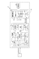
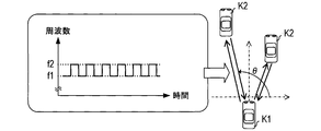
- FIG. 1 is a block diagram illustrating a schematic configuration of an in-vehicle system according to an embodiment of the present disclosure. It is explanatory drawing showing the transmission / reception aspect of the radar wave which concerns on embodiment of this indication content. It is a functional block diagram showing the function implement
- the in-vehicle system 1 includes a radar device 10 and a driving assistance ECU 100.
- This in-vehicle system 1 is mounted on a vehicle K1 such as a four-wheeled vehicle.
- the radar apparatus 10 emits a radar wave, receives the reflected wave, and based on the received signal, the distance R from the apparatus 10 to the target T, which is a forward object that reflects the radar wave, the target.
- the velocity V of T and the azimuth ⁇ of the target T are observed.
- the radar apparatus 10 inputs these observation values (R z , V z , ⁇ z ) to the driving support ECU 100.
- the radar apparatus 10 of the present embodiment is configured as a dual-frequency CW type radar apparatus.
- the radar apparatus 10 includes a transmission circuit 20, a distributor 30, a transmission antenna 40, a reception antenna 50, a reception circuit 60, a processing unit 70, and an output unit 80.
- the transmission circuit 20 is a circuit for supplying the transmission signal Ss to the transmission antenna 40.
- the transmission circuit 20 inputs a millimeter-wave band high-frequency signal to a distributor 30 located upstream of the transmission antenna 40.
- the transmission circuit 20 alternately includes a high-frequency signal having a first frequency (f1) and a high-frequency signal having a second frequency (f2) slightly different from the first frequency (f1) at short time intervals. Are input to the distributor 30.
- the distributor 30 converts the high-frequency signal input from the transmission circuit 20 into a transmission signal Ss and local signals L (f1) and L having the first frequency (f1) and the second frequency (f2) of the high-frequency signal, respectively.
- the power is distributed to (f2).
- the transmission antenna 40 Based on the transmission signal Ss supplied from the distributor 30, the transmission antenna 40 emits a radar wave having a frequency corresponding to the transmission signal Ss, for example, ahead of the host vehicle K1. Thereby, as shown in the left area of FIG. 2, the radar wave of the first frequency (f1) and the radar wave of the second frequency (f2) are alternately output.
- the receiving antenna 50 is an antenna for receiving a radar wave (reflected wave) reflected from a target.
- the receiving antenna 50 is configured as, for example, a linear array antenna in which a plurality of antenna elements 51 are arranged in a line.
- a reception signal Sr of a reflected wave from each antenna element 51 is input to the reception circuit 60.
- the reception circuit 60 processes the reception signal Sr input from each antenna element 51 constituting the reception antenna 50 to generate and output a beat signal BT for each antenna element 51. Specifically, for each antenna element 51, the receiving circuit 60 converts the received signal Sr input from the antenna element 51 and the local signals L (f 1) and L (f 2) input from the distributor 30 through the mixer 61. By using and mixing, a beat signal BT for each antenna element 51 is generated and output.
- the receiving circuit 60 as a process until the beat signal BT is output, (i) A process of amplifying the reception signal Sr input from each antenna element 51 (ii)
- the antenna element is obtained by mixing the received signal Sr input and amplified from each antenna element 51 and the local signals L (f1) and L (f2) input from the distributor 30 using the mixer 61.
- Process of generating beat signal BT every 51 (iii) a process of removing unnecessary signal components from the generated beat signal BT for each antenna element 51, and (iv) A process of converting the beat signal BT for each antenna element 51 from which unnecessary components are removed into digital data is included.
- the receiving circuit 60 converts the generated beat signal BT for each antenna element 51 into digital data and outputs the digital data.
- the output beat signal BT for each antenna element 51 is input to the processing unit 70.
- the processing unit 70 calculates the observed value (R z , V z , ⁇ z ) for each target T that reflects the radar wave by analyzing the beat signal BT for each antenna element 51.
- the observed value R z is an observed value of the distance R from the radar device 10 (in other words, the host vehicle K1 on which the radar device 10 is mounted) to each target T
- the observed value V z is the value of each target T. This is an observed value of the relative speed V with respect to the host vehicle K1.
- the observed value ⁇ z is based on the arrangement direction of the antenna elements 51 orthogonal to the front-rear direction of the host vehicle K1, and the observed value about the direction ⁇ (see the right region in FIG. 2) of each target T from this reference. It is.
- a solid line arrow in the right region of FIG. 2 simply indicates the propagation direction of the radar wave in an environment where the radar wave is reflected by the front vehicle K2, which is the target T in front of the host vehicle K1.
- a method of calculating observed values (R z , V z , ⁇ z ) for each target T from the beat signal BT based on each antenna element 51 is known. Therefore, here, a method of calculating the observation values (R z , V z , ⁇ z ) in the processing unit 70 will be briefly described.
- the processing unit 70 for each antenna element 51 includes first and second beat signals BT included in each antenna element 51. Fourier transform the two-beat signal. As a result, the first and second beat signals are converted into signals in the frequency domain.
- the first beat signal here is a beat signal BT generated when the mixer 61 mixes the received signal Sr and the local signal L (f1) of the first frequency (f1).
- the beat signal is a beat signal BT generated when the mixer 61 mixes the received signal Sr and the local signal L (f2) of the second frequency (f2). Since the time required for transmission / reception of the radar wave is very small, the first beat signal includes a reflected wave component of the radar wave of the first frequency (f1), and the second beat signal includes the second frequency (f2). The reflected wave component of the radar wave is included.
- the average of the power spectrum is calculated, and from this average, the peak frequency that is the frequency at which the power is equal to or higher than the threshold is detected.
- a plurality of peak frequencies are detected, it is estimated that there are a plurality of targets T.
- there is one peak frequency it is estimated that there is one target T.
- the signal components of the first and second beat signals corresponding to the peak frequency correspond to the reflected wave component of the corresponding target T. Note that since the frequency difference between the first frequency (f1) and the second frequency (f2) is slight, the difference in peak frequency between the first and second beat signals can be ignored. .
- the processing unit 70 calculates an observation value V z for the relative velocity V of each corresponding target T from the information on the peak frequency for each peak frequency. Furthermore, the processing unit 70 is based on the phase difference between the reflected wave component of the first beat signal BT corresponding to the peak frequency and the reflected wave component of the second beat signal BT corresponding to the peak frequency for each peak frequency. Thus, the observed value R z for the distance R to each corresponding target T is calculated. In addition, for each peak frequency, the observed value ⁇ z for each azimuth ⁇ of the corresponding target T from the phase difference between the antenna elements for the reflected wave components of the first and second beat signals BT corresponding to the peak frequency. Is calculated.
- the processing unit 70 calculates the observed value V z for the relative velocity V for each target T from the frequency information of the beat signal BT obtained for each antenna element 51, and is obtained for each antenna element 51. From the phase information of the beat signal BT, the observed value R z and the observed value ⁇ z for the distance R and azimuth ⁇ for each target T are calculated. Then, the processing unit 70 inputs the observation values (R z , V z , ⁇ z ) for each target T to the driving support ECU 100 via the output unit 80.
- the driving assistance ECU 100 includes a control unit 110 and an input unit 120.
- the control unit 110 estimates the state of each target T based on the observation values (R z , V z , ⁇ z ) for each target T input from the radar apparatus 10 via the input unit 120. Based on the estimation result, the control unit 110 executes a process for supporting the driving of the vehicle by the driver.
- the control unit 110 includes a CPU 111 that executes processes according to various programs, a ROM 113 that stores these various programs, and a RAM 115 that is used as a work area when the CPU 111 executes processes.
- ROM 113 for example, an electrically rewritable nonvolatile memory such as a flash memory can be adopted.
- Various processes including a process related to state estimation and a process related to driving support are realized by the CPU 111 executing processes according to the program.
- the control unit 110 executes a process of displaying a warning to the driver of the vehicle K1 that there is an approaching object, for example, by controlling a display device as the control target 200 as a process related to driving support.
- the control unit 110 controls the brake system, steering system, and the like of the vehicle K1 as the control target 200 as processing related to driving support, thereby avoiding a collision between the vehicle K1 and an approaching object with respect to the vehicle K1. Carry out vehicle control.
- the driving support ECU 100 is connected to the controlled object 200 via a dedicated line or via a vehicle network so as to be controllable.
- Vehicle control via the in-vehicle network is realized by cooperation between an electronic control unit (ECU) in the in-vehicle network such as an engine ECU, a brake ECU, and a steering ECU and the driving support ECU 100, for example.
- ECU electronice control unit
- the engine ECU is an electronic control device that controls the internal combustion engine of the vehicle K1
- the steering ECU is an electronic control device that performs steering control of the vehicle K1
- the brake ECU performs braking control of the vehicle K1. It is an electronic control device.
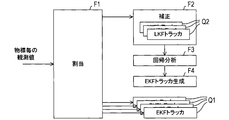
- control unit 110 generates an EKF tracker Q1 for each target T as shown in FIG. 3 when estimating the state of each target T based on the observed values (R z , V z , ⁇ z ). And the state estimation of each target T using this EKF tracker Q1 is performed.
- the EKF tracker Q1 is a tracker that performs state estimation of the corresponding target T using an extended Kalman filter (EKF).
- the extended Kalman filter is a Kalman filter that estimates a state quantity by linearly approximating a nonlinear state space model.
- the tracker is generated as an object or task executed by the control unit 110, for example.
- the processing realized by the tracker may be described using an expression with the tracker as the execution subject of the process, but this expression means that the control unit 110 executes the process corresponding to the tracker. .
- the control unit 110 sets an initial value for the state quantity of the corresponding target T in the EKF tracker Q1. Set. In this setting, the control unit 110 realizes a characteristic processing operation by the functions F1 to F4 shown in FIG.
- the control unit 110 assigns the observation values (R z , V z , ⁇ z ) of each target T obtained from the radar apparatus 10 to the corresponding EKF tracker Q1 (allocation function F1). However, when an observation value (R z , V z , ⁇ z ) of a new target that is not tracked by the EKF tracker Q1 occurs, the control unit 110 generates the LKF tracker Q2. Then, the observed values (R z , V z ) corresponding to the LKF tracker Q2 are assigned, and the observed values (R z , V z ) are corrected, that is, smoothed (correcting function F2).
- the LKF tracker Q2 is a tracker that performs state estimation of a corresponding target using a linear Kalman filter (LKF).
- the linear Kalman filter is a Kalman filter that estimates a state quantity based on a linear state space model.
- the LKF tracker Q2 follows the simple one-dimensional linear motion model in which the motion of the corresponding target in the direction of the distance R is modeled, and the distance R to the target and the relative velocity V to the target. Is configured as a tracker for estimating a state quantity (R, V) including.
- the LKF tracker Q2 performs state estimation without using the observed value ⁇ z for the direction ⁇ . That is, the LKF tracker Q2 estimates the state quantities (R, V) of the corresponding target using the observed values (R z , V z ) for the distance R and the relative velocity V.
- the control unit 110 uses the LKF tracker Q2 to correct the a posteriori estimated value of the state quantity (R, V) of the corresponding target at each time in the past even after the start of the estimation, and the observed value (R c , V c ) after correction. To perform subsequent processing. That is, as the subsequent processing, the control unit 110 performs a characteristic linear regression analysis using the corrected observation values (R c , V c ) as samples (regression analysis function F3). As a result, the highly accurate estimation of the distance R to the corresponding target at each past time is performed even at the start of the above estimation.
- control unit 110 which while generating EKF tracker Q1 to the corresponding target object, by using the estimated value R e of the distance R, to determine the initial value of the state amount to be set in EKF tracker Q1, generated The initial value is set in the tracker Q1 (EKF tracker generation function F4).
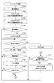
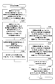
- control unit 110 repeatedly executes the tracking process in FIG. 4 for each sampling period of the observed values (R z , V z , ⁇ z ).
- the functions F1 to F4 described above are realized, and the state of the target is estimated using the EKF tracker Q1.
- the control unit 110 takes in the observed values (R z , V z , ⁇ z ) for each target T obtained from the radar apparatus 10 (S110). Thereafter, the observed value for each target T (R z, V z, ⁇ z) of the observed value of the target object being tracked by EKF tracker Q1 (R z, V z, ⁇ z) of the respective, The corresponding target EKF tracker Q1 is assigned (S120).
- control unit 110 the remaining observations (R z, V z, ⁇ z) of the observed value of the target object being tracked by LKF tracker Q2 (R z, V z, ⁇ z) each of s Are assigned to the LKF tracker Q2 of the corresponding target (S130).
- the control unit 110 In S150, the control unit 110 generates a new LKF tracker Q2 for each new target. In each of the generated LKF trackers Q2, the observed value (R z , V z ) of the corresponding new target is set as the initial value of the state quantity (R, V). Thereafter, the process proceeds to S160. On the other hand, if there is no observation value (R z , V z ) of the new target and a negative determination is made in S140, the control unit 110 skips S150 and proceeds to S160.
- control unit 110 determines whether or not the processes after S180 have been executed for all the generated trackers. If it is determined that it is not executed (No in S160), the process proceeds to S170. In S170, the control unit 110 selects one of the unprocessed trackers as a processing target for the processes in and after S180 from the generated tracker group.
- the generated tracker group referred to here is a group of trackers other than the tracker newly generated in the current tracking process in the group of the generated EKF tracker Q1 and LKF tracker Q2.
- the tracker newly generated in this tracking process is excluded from the selection target in S170.
- the control unit 110 proceeds to S180 and determines whether or not the target tracked by the selected tracker has disappeared.
- the determination as to whether or not the target has disappeared is realized by determining whether or not the observed values (R z , V z , ⁇ z ) of the target corresponding to the tracker are continuously missing for a predetermined number of times. be able to.
- control unit 110 deletes this tracker, ends tracking of the corresponding target, moves to S160, and selects a tracker to be processed. Switch.
- the control unit 110 executes a process of updating the tracker to be processed (S190).
- the tracker to be processed is caused to calculate the a posteriori estimated value of the state quantity at the current time based on the observed values (R z , V z , ⁇ z ) (S190). Thereby, the state quantity of the target held by the tracker to be processed is updated.
- the a posteriori estimated value of the target state quantity (X, Y, Vx, Vy) based on the extended Kalman filter is calculated (updated) by this tracker.
- the state quantity Y represents the Y coordinate of the position of the target in the XY coordinate system when the front-rear direction of the host vehicle is the Y axis
- the state quantity X is the position of the target in the XY coordinate system and represents the X coordinate.
- the X-axis direction is a direction orthogonal to the Y-axis and parallel to the ground (in other words, the arrangement direction of the antenna elements 51).
- Vy represents the Y-axis direction component of the relative speed of the target to the host vehicle
- Vx represents the X-axis direction component of the relative speed of the target to the host vehicle.
- the state quantities (X, Y, Vx, Vy) are updated based on the observed values (R z , V z , ⁇ z ) and the prior estimated values of the state quantities (X, Y, Vx, Vy).
- a prior estimated value of the state quantity (X, Y, Vx, Vy) corresponding to the initial value is used.
- the control unit 110 assumes that the prior estimated value of the state quantity (X, Y, Vx, Vy) corresponds to the observed value (R z , V z , ⁇ z ), and the state quantity (X , Y, Vx, Vy).
- the a posteriori estimated value of the target state quantity (R, V) based on the linear Kalman filter is calculated (updated) by this tracker.
- the state quantities (R, V) are updated based on the observed values (R z , V z ) and the prior estimated values of the state quantities (R, V). As described above, in estimating the state quantities (R, V), the observed value ⁇ z of the azimuth ⁇ is not used.
- the a posteriori estimated value of the state quantity (R, V) calculated by the LKF tracker Q2 is used in subsequent processing as a correction value (R c , V c ) of the observed value (R z , V z ).
- the control unit 110 uses the posterior estimated value (R c , V c ) calculated by the LKF tracker Q2 in S190 together with the observed value ⁇ z of the azimuth ⁇ observed together with the observed values (R z , V z ).
- the corrected observation values (R c , V c , ⁇ z ) corresponding to the observation values (R z , V z , ⁇ z ) are stored in, for example, the RAM 115 or the like.
- the control unit 110 stores the current number of updates of the processing target tracker in the RAM 115, for example.
- the control unit 110 switches processing depending on whether or not the processing target tracker is the LKF tracker Q2 (S200). Specifically, if the tracker to be processed is not the LKF tracker Q2 but the EKF tracker Q1 (No in S200), the control unit 110 skips S210 and S220 and proceeds to S160.
- the control unit 110 stores the number of updates in S210 of the tracker to be processed in S190, that is, the RAM 15 or the like by the process in step S190. It is determined whether or not the number of updates performed is equal to or greater than a specified number (N + 1).
- control unit 110 proceeds to S220, generates an EKF tracker Q1 that replaces the LKF tracker Q2 to be processed, and this EFK tracker Q1
- the analysis generation process shown in FIG. 5 including the procedure for setting the initial value is executed. Thereafter, the process proceeds to S160.
- the control unit 110 makes a negative determination in S210, skips S220, and proceeds to S160.
- control unit 110 sequentially selects each of the trackers belonging to the generated tracker group as a processing target (S170), executes the processing after S180, and the state of the target held by each tracker Q1, Q2 Update quantity.
- the number of updates of the LKF tracker Q2 is equal to or greater than the specified number (N + 1)
- the analysis generation process shown in FIG. 5 is executed (S220), and the LKF tracker Q2 is switched to the EKF tracker Q1.
- control unit 110 performs the analysis generation process shown in FIG. 5, so that the N + 1 observation values (R c ) including the corrected observation values (R c , V c ) regarding the new target are obtained. , V c , ⁇ z ), and an EKF tracker Q1 with appropriate initial values is generated from these observation values (R c , V c , ⁇ z ). Thereafter, state estimation using the EKF tracker Q1 is performed for this target.
- the constant T used in the equation [1] is the tracking processing execution period T shown in FIG. 4 and coincides with the sampling period T of the observed values (R z , V z , ⁇ z ).
- step S330 the control unit 110 performs linear regression analysis using the distance R as the objective variable and the displacement ⁇ as the explanatory variable, and the observed value (R) at each time in the predetermined period. c ) and a regression analysis using the observed value ( ⁇ c ) at each time as a sample.
- X e [n] R e [n] ⁇ cos ( ⁇ z [n]) [3]
- Y e [n] R e [n] ⁇ sin ( ⁇ z [n]) [4]
- a function X (t) representing a change in the position of the target in the X-axis direction is calculated by linear regression analysis using n] as a sample (S360).
- Vx0 the X-axis direction component of the relative velocity V
- the function Y (t) representing the position change of the target in the Y-axis direction is calculated by linear regression analysis using n] as a sample (S370).
- Vy0 the Y-axis direction component of the relative velocity V
- the control unit 110 sets the slope Vx0 of the function X (t) as the initial value of the state quantity Vx, and sets the slope Vy0 of the function Y (t) as the initial value of the state quantity Vy.
- the control unit 110 ends the analysis generation process.
- the initial value is set in the EKF tracker Q1 by such a procedure. Then, regarding this target, the control unit 110 performs state estimation using the EKF tracker Q1.
- the control unit 110 uses the LKF tracker Q2 before setting an initial value for the EKF tracker Q1.
- the observed value (R z , V z ) of the corresponding new target obtained from the radar apparatus 10 is corrected (smoothed).
- the control unit 110 sets an initial value for the EKF tracker Q1 based on the corrected observed values (R c , V c ).
- the observation value Rz for the distance R to the target is calculated from the phase information included in the received signal of the reflected wave as described above. Therefore, the accuracy of the observations R z is poor, there is a possibility that a large variation in the observed value R z.
- the variation can be suppressed. Therefore, in the control unit 110 according to this embodiment, it is possible to suppress the low observation accuracy of the distance R in the radar device 10 from adversely affecting the setting of the initial value for the EKF tracker Q1.
- the control unit 110 uses the difference in accuracy to estimate the distance R to the target with high accuracy by the processes of S310, S330, and S340 described above.
- an estimated value of the distance R corresponding to the observed value R z is calculated by linear regression analysis using the time t as an explanatory variable and the distance R as an objective variable, and an initial value for the tracker is set based on the estimated value. It was.
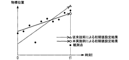
- the regression line obtained by the regression analysis is greatly affected by the observed value R z of the distance R having a large error from the true value. Therefore, the position of the target as the initial value of the state quantity set to the tracker at time t1 based on the regression line is a value greatly deviated from the true value as represented by triangular plot points in FIG. turn into. In addition, the relative speed of the target as the initial value of the state quantity set from the slope of the regression line becomes a value greatly deviated from the true value.
- the displacement amount ⁇ c is used as the explanatory variable, and the distance R is used as the target variable, using the displacement amount ⁇ c based on the observed value V c of the highly accurate velocity V. Perform regression analysis.
- the estimated value R e of the distance R corresponding to the observed value R c Therefore, by suppressing the influence of the large observed value of the error from the true value can be obtained a highly accurate estimate R e.
- the position of the target as the initial value of the state quantity is true for the EKF tracker Q1, as represented by the white circle in FIG. It can be appropriately set as a value with a small error from the value. Further, as a result of obtaining a highly accurate regression equation, the relative speed of the target as the initial value of the state quantity can be appropriately set as a value with a small error from the true value.
- an appropriate initial value can be set as described above.
- the EKF tracker Q1 after the time t1 when the initial value is set is used.
- the dashed-dotted line shown in FIG. 7 represents the locus of the estimated value of the state quantity by the EKF tracker Q1 when a value larger than the true value is set as the initial value of the state quantity.
- the EKF tracker Q1 calculates the estimated value of the state quantity as a value deviating upward from the true value.
- the EKF tracker Q1 it is not possible to perform state estimation with high accuracy in the initial stage of target state estimation by the EKF tracker Q1.
- control unit 110 when the target position (R, ⁇ ) is converted into the XY coordinate system and the initial value is set in the EKF tracker Q1, the observed value of the azimuth ⁇ is measured. Considering that ⁇ z also includes errors, further regression analysis was performed.
- the control unit 110 uses the estimated value (R e [n], ⁇ z [n]) of the target position as the estimated value (X e ) of the position (X, Y) in the XY coordinate system. [N], Y e [n]) (S350), the estimated values (X e [n], Y e [n]) are further subjected to linear regression analysis (S360, S370).
- the control unit 110 sets an initial value according to the result of the regression analysis for the EKF tracker Q1, thereby suppressing an error in the initial value due to the observation error of the azimuth ⁇ .
- control unit 110 According to the control unit 110 according to the present embodiment, a more appropriate initial value can be set, and a good system can be constructed as a target state estimation system using the EKF tracker Q1.
- the control unit 110 corrects (smooths) the observation values (R z , V z ) obtained from the radar device 10 using the LKF tracker Q2, and the observation values (R c , with V c), and to calculate the estimated value R e of the distance R of the target.
- the control unit 110 does not calculate the estimated value R e , but the observed values (R z , V z ) obtained from the radar device 10 instead of the observed values (R c , V c ) corrected by the LKF tracker Q2. It is also possible to use.
- the control unit 110 in S310 ⁇ S340 of analyzing generation process, the observed value (R c, V c) the same processing as in the case of using the observed value instead of the observed value (R c, V c) (R z, V z) was performed using the estimated value R e of the distance R may be calculated.
- control unit 110 for setting the initial values for EKF tracker Q1 by the procedure of S310 ⁇ S340, has been calculated estimated value R e of the distance R, the present disclosure, It is also possible to utilize this calculation technique for purposes other than setting initial values.
- the calculation technique of the estimated value R e of the distance R according to the procedure of S310 to S340 uses the high observation accuracy of the velocity V when the observation accuracy of the distance R is worse than the observation accuracy of the velocity V.
- the driving assistance ECU 100 of the present embodiment corresponds to an example of an estimation device
- the radar device 10 corresponds to an example of an observation device.
- the process of S310 executed by the control unit 110 of the driving support ECU 100 corresponds to an example of the process realized by the displacement amount calculation means
- the processes of S330 and S340 executed by the control unit 110 are realized by the distance estimation means. This corresponds to an example of processing to be performed.
- the processes of S130 to S150 and S190 executed by the control unit 110 correspond to an example of the process realized by the correcting means, and the processes of S350 to S370 executed by the control unit 110 are realized by the position estimating means.
- the processing of S350 corresponds to an example of processing realized by the conversion means.
- the update process of the state quantity held by the EKF tracker Q1 realized by S190 executed by the control unit 110 corresponds to an example of the process realized by the state estimation unit, and the process of S390 executed by the control unit 110 is as follows. This corresponds to an example of processing realized by the initial value setting means.
Landscapes
- Engineering & Computer Science (AREA)
- Radar, Positioning & Navigation (AREA)
- Remote Sensing (AREA)
- Physics & Mathematics (AREA)
- General Physics & Mathematics (AREA)
- Computer Networks & Wireless Communication (AREA)
- Electromagnetism (AREA)
- Radar Systems Or Details Thereof (AREA)
Abstract
Description
つまり、位相情報から得られる距離の観測精度は、周波数情報から得られる速度の観測精度に比べて劣っている(例えば、文献:Steven M. Kay, “Fundamentals of Statistical Signal Processing Vol1. Estimation Theory, pp. 56-57の3.41式参照)。
すなわち、本開示内容の一態様は、前方物体までの距離及び前方物体の速度を観測する観測装置から得られる観測値に基づいて、高精度に前方物体までの距離を推定可能な技術を提供することを目的とする。
また、本開示内容の他の態様は、状態推定フィルタに与える状態量の初期値を高精度に設定可能な技術を提供することを目的とする。
この推定装置によれば、速度の観測精度が距離の観測精度よりも高い場合、時間対距離の関係に従って距離の観測値を標本とした線形回帰分析を行う従来技術よりも、上記期間の開始時刻における前方物体までの距離を高精度に推定することができる。
具体的に、状態推定フィルタを用いて前方物体の位置及び速度を推定する状態推定部を備える推定装置には、次の初期値設定部を設けることができる。
図1に示す本実施形態の車載システム1は、レーダ装置10と運転支援ECU100とを備える。この車載システム1は、四輪自動車等の車両K1に搭載される。
送信回路20は、送信アンテナ40に送信信号Ssを供給するための回路である。送信回路20は、ミリ波帯の高周波信号を、送信アンテナ40の上流に位置する分配器30に入力する。具体的に、送信回路20は、短い時間間隔で交互に、第一周波数(f1)の高周波信号と、第一周波数(f1)とは僅かに周波数の異なる第二周波数(f2)の高周波信号と、を生成して分配器30に入力する。
送信アンテナ40は、分配器30から供給される送信信号Ssに基づいて、送信信号Ssに対応する周波数のレーダ波を自車両K1の例えば前方に発射する。これにより、図2左領域に示すように、第一周波数(f1)のレーダ波と、第二周波数(f2)のレーダ波とを交互に出力する。
(i)各アンテナ素子51から入力される受信信号Srを増幅する過程
(ii)各アンテナ素子51から入力され、かつ増幅された受信信号Srと分配器30から入力されるローカル信号L(f1)およびL(f2)とをミキサ61を用いて混合することによりアンテナ素子51毎のビート信号BTを生成する過程
(iii)生成されたアンテナ素子51毎のビート信号BTから不要な信号成分を除去する過程、および
(iv)不要成分が除去されたアンテナ素子51毎のビート信号BTをディジタルデータに変換する過程
が含まれている。
このように、受信回路60は、生成したアンテナ素子51毎のビート信号BTをディジタルデータに変換して出力する。出力されたアンテナ素子51毎のビート信号BTは、処理ユニット70に入力される。
即ち、制御ユニット110は、上記後続の処理として、補正後の観測値(Rc,Vc)を標本として用いた特徴的な線形回帰分析を行う(回帰分析機能F3)。これによって、上記推定開始時によりも過去の各時刻における対応する物標までの距離Rについての高精度な推定を行う。そして、制御ユニット110は、対応する物標に対するEKFトラッカQ1を生成しつつ、この距離Rの推定値Reを用いて、EKFトラッカQ1に設定する状態量の初期値を決定し、生成したEKFトラッカQ1に当該初期値を設定する(EKFトラッカ生成機能F4)。


Xe[n]=Re[n]・cos(θz[n]) [3]
Ye[n]=Re[n]・sin(θz[n]) [4]
その後、制御ユニット110は、上記変換により得られた各時刻t=nT(n=0,…,N)の位置推定値(Xe[n],Ye[n])のX座標Xe[n]を標本として用いた線形回帰分析により、物標のX軸方向の位置変化を表す関数X(t)を算出する(S360)。
しかしながら、本実施形態に係る制御ユニット110によるLKFトラッカQ2を用いた補正によれば、そのばらつきを抑えることができる。従って、本実施形態に係る制御ユニット110においては、レーダ装置10における距離Rの観測精度の低さがEKFトラッカQ1に対する初期値の設定に悪影響を与えるのを抑えることができる。
以上に、本開示内容の一実施形態について説明したが、本開示内容は、上記実施形態に限定されるものではなく、種々の態様を採ることができる。
本実施形態の運転支援ECU100は、推定装置の一例に対応し、レーダ装置10は、観測装置の一例に対応する。そして、運転支援ECU100の制御ユニット110が実行するS310の処理は、変位量算出手段によって実現される処理の一例に対応し、制御ユニット110が実行するS330,S340の処理は、距離推定手段によって実現される処理の一例に対応する。
Claims (14)
- 前方物体までの距離(R)及び前記前方物体の速度(V)を観測する観測装置(10)による所定期間における複数の時刻それぞれの前記速度(V)の観測値(Vz)に基づき、前記時刻毎に、前記期間の開始時刻から対応する時刻までの前記前方物体の変位量(δ)に関する観測値(δz)として、前記開始時刻から前記対応する時刻までの前記観測値(Vz)の時間積分値を算出する変位量算出手段(110,S310)と、
目的変数として前記距離(R)を用い、且つ、説明変数として前記変位量(δ)を用いた回帰分析であって、前記観測装置による前記所定期間における前記各時刻の前記距離(R)の観測値(Rz)、及び、前記各時刻の前記観測値(δz)を標本として用いた回帰分析を実行し、当該回帰分析により算出された回帰式に従う前記変位量(δ)がゼロであるときの前記距離(R)の値を、前記開始時刻における前記前方物体までの前記距離(R)の値であると推定する距離推定手段(110,S330,S340)と、
を備えることを特徴とする推定装置。 - 線形状態空間モデルに基づく状態推定フィルタを用いた前記前方物体の状態推定によって、前記各時刻の前記観測値(Rz)及び前記観測値(Vz)を補正する補正手段(110,S130~S150,S190)をさらに備え、前記変位量算出手段は、前記各時刻の観測値(δz)として、前記補正手段による補正後の前記観測値(Vc)の時間積分値(δc)を算出し、前記距離推定手段は、前記補正手段による補正後の前記各時刻の観測値(Rc)、及び、前記各時刻の前記観測値(δc)を標本として用いて、前記回帰分析を実行することを特徴とする請求項1記載の推定装置。
- 前記線形状態空間モデルに基づく状態推定フィルタは、線形カルマンフィルタであることを特徴とする請求項2記載の推定装置。
- 前記距離推定手段は、前記推定した前記開始時刻における前記距離(R)と前記各時刻の前記観測値(δz)との加算値を、前記各時刻における前記前方物体までの前記距離(R)として推定することを特徴とする請求項1記載の推定装置。
- 前記距離推定手段は、前記推定した前記開始時刻における前記距離(R)と前記各時刻の前記観測値(δz)との加算値を、前記各時刻における前記前方物体までの前記距離(R)として推定することを特徴とする請求項2記載の推定装置。
- 前記距離推定手段は、前記推定した前記開始時刻における前記距離(R)と前記各時刻の前記観測値(δz)との加算値を、前記各時刻における前記前方物体までの前記距離(R)として推定することを特徴とする請求項3記載の推定装置。
- 前記観測装置は、前記前方物体の方位θを更に観測する装置であり、
前記推定装置は、前記距離推定手段により推定された前記各時刻における前記距離(R)と、前記観測装置による前記方位(θ)の観測値(θz)とに基づき、直交座標系での前記各時刻(t)における前記前方物体の位置{P(t)}を推定する位置推定手段(110,S350~S370)をさらに備えることを特徴とする請求項4記載の推定装置。 - 前記位置推定手段は、前記距離推定手段により推定された前記各時刻における前記距離(R)及び前記観測値(θz)から特定される極座標系での前記各時刻の前記前方物体の位置(R,θz)を、前記直交座標系であるXY座標系での前記各時刻の前記前方物体の位置(Xz,Yz)に、変換する変換手段(110,S350)を備え、前記変換によって得られた前記各時刻の前記位置(Xz,Yz)のX座標(Xz)標本として用いた回帰分析により、時刻(t)と前記前方物体の位置のX座標との対応関係を表す関数{X(t)}を算出する一方、前記各時刻の前記位置(Xz,Yz)のY座標(Yz)を標本として用いた回帰分析により、時刻(t)と前記前方物体の位置のY座標との対応関係を表す関数{Y(t)}を算出し、これによって、前記各時刻における前記前方物体の位置{P(t)=(X(t),Y(t))}を推定することを特徴とする請求項7記載の推定装置。
- 非線形状態空間モデルに基づく状態推定フィルタを用いて前記前方物体の位置及び速度を推定する状態推定手段(110,S190,Q1)と、前記状態推定手段が用いる前記状態推定フィルタに対し、前記前方物体の位置及び速度に関する初期値として、前記位置推定手段により推定された前記位置{P(t)}から特定される前記初期値に対応する時刻での位置及び速度を設定する初期値設定手段(110,S390)と、をさらに備えることを特徴とする請求項7記載の推定装置。
- 非線形状態空間モデルに基づく状態推定フィルタを用いて前記前方物体の位置及び速度を推定する状態推定手段(110,S190,Q1)と、前記状態推定手段が用いる前記状態推定フィルタに対し、前記前方物体の位置及び速度に関する初期値として、前記位置推定手段により推定された前記位置{P(t)}から特定される前記初期値に対応する時刻での位置及び速度を設定する初期値設定手段(110,S390)と、をさらに備えることを特徴とする請求項8記載の推定装置。
- 前記非線形状態空間モデルに基づく状態推定フィルタは、非線形カルマンフィルタであることを特徴とする請求項10記載の推定装置。
- 前記非線形カルマンフィルタは、拡張カルマンフィルタであることを特徴とする請求項11記載の推定装置。
- 前記観測装置は、レーダ波を発射して反射波を受信し、前記反射波の受信信号に含まれる周波数情報から、前記前方物体の前記速度(V)を観測し、前記受信信号に含まれる位相情報から前記前方物体までの前記距離(R)を観測する装置であることを特徴とする請求項1記載の推定装置。
- 前記観測装置は、二周波CW(Dual Frequency Continuous Wave)方式によりレーダ波を発射し、前記前方物体による前記レーダ波の反射に基づく反射波を受信し、前記反射波の受信信号から前記前方物体までの前記距離(R)及び前記前方物体の速度(V)を観測する装置であることを特徴とする請求項1記載の推定装置。
Priority Applications (3)
| Application Number | Priority Date | Filing Date | Title |
|---|---|---|---|
| CN201480011993.0A CN105008954B (zh) | 2013-03-04 | 2014-03-04 | 推定装置 |
| US14/772,691 US10077979B2 (en) | 2013-03-04 | 2014-03-04 | Estimation apparatus |
| DE112014001120.7T DE112014001120T5 (de) | 2013-03-04 | 2014-03-04 | Schätzvorrichtung |
Applications Claiming Priority (2)
| Application Number | Priority Date | Filing Date | Title |
|---|---|---|---|
| JP2013041882A JP6266887B2 (ja) | 2013-03-04 | 2013-03-04 | 推定装置 |
| JP2013-041882 | 2013-03-04 |
Publications (1)
| Publication Number | Publication Date |
|---|---|
| WO2014136754A1 true WO2014136754A1 (ja) | 2014-09-12 |
Family
ID=51491270
Family Applications (1)
| Application Number | Title | Priority Date | Filing Date |
|---|---|---|---|
| PCT/JP2014/055403 Ceased WO2014136754A1 (ja) | 2013-03-04 | 2014-03-04 | 推定装置 |
Country Status (5)
| Country | Link |
|---|---|
| US (1) | US10077979B2 (ja) |
| JP (1) | JP6266887B2 (ja) |
| CN (1) | CN105008954B (ja) |
| DE (1) | DE112014001120T5 (ja) |
| WO (1) | WO2014136754A1 (ja) |
Cited By (5)
| Publication number | Priority date | Publication date | Assignee | Title |
|---|---|---|---|---|
| EP2998762A1 (en) * | 2014-09-17 | 2016-03-23 | Honda Motor Co., Ltd. | Object recognition apparatus |
| US20160299216A1 (en) * | 2015-04-08 | 2016-10-13 | Denso Corporation | Axial misalignment determination apparatus |
| JP2018059873A (ja) * | 2016-10-07 | 2018-04-12 | 株式会社Soken | 物体検出装置 |
| US10077979B2 (en) | 2013-03-04 | 2018-09-18 | Denso Corporation | Estimation apparatus |
| CN109617839A (zh) * | 2018-11-21 | 2019-04-12 | 重庆邮电大学 | 一种基于卡尔曼滤波算法的莫尔斯信号检测方法 |
Families Citing this family (8)
| Publication number | Priority date | Publication date | Assignee | Title |
|---|---|---|---|---|
| WO2016096635A1 (en) * | 2014-12-17 | 2016-06-23 | Koninklijke Philips N.V. | Method and system for calculating a displacement of an object of interest |
| JP6716984B2 (ja) | 2016-03-16 | 2020-07-01 | 株式会社デンソー | 物標検出装置 |
| JP7060441B2 (ja) * | 2018-05-10 | 2022-04-26 | 株式会社デンソーテン | レーダ装置および物標検出方法 |
| US11391832B2 (en) * | 2018-10-10 | 2022-07-19 | Massachusetts Institute Of Technology | Phase doppler radar |
| JP7197456B2 (ja) * | 2019-10-15 | 2022-12-27 | 株式会社Soken | 物体追跡装置 |
| KR102775306B1 (ko) * | 2019-11-21 | 2025-03-05 | 삼성전자주식회사 | 운동 정보 결정 방법 및 장치 |
| US20230003872A1 (en) * | 2021-06-30 | 2023-01-05 | Zoox, Inc. | Tracking objects with radar data |
| EP4220224B1 (en) * | 2022-01-26 | 2025-05-21 | Robert Bosch GmbH | Method and device for detecting and tracking objects and driver assistance system |
Citations (7)
| Publication number | Priority date | Publication date | Assignee | Title |
|---|---|---|---|---|
| JPH08124080A (ja) * | 1994-10-20 | 1996-05-17 | Honda Motor Co Ltd | 車両の障害物検出装置 |
| JP2001272466A (ja) * | 2000-03-27 | 2001-10-05 | Toyota Central Res & Dev Lab Inc | レーダ装置 |
| JP2008203095A (ja) * | 2007-02-20 | 2008-09-04 | Mitsubishi Electric Corp | 運動諸元推定装置 |
| JP2008249427A (ja) * | 2007-03-29 | 2008-10-16 | Toyota Motor Corp | 移動体用測位装置及び移動体用測位方法 |
| JP2010091407A (ja) * | 2008-10-08 | 2010-04-22 | Furuno Electric Co Ltd | 測位装置 |
| JP2010256083A (ja) * | 2009-04-22 | 2010-11-11 | Mitsubishi Electric Corp | レーダ装置 |
| JP2013120127A (ja) * | 2011-12-07 | 2013-06-17 | Mitsubishi Electric Corp | 目標追尾装置 |
Family Cites Families (15)
| Publication number | Priority date | Publication date | Assignee | Title |
|---|---|---|---|---|
| JP3256332B2 (ja) * | 1993-05-24 | 2002-02-12 | 郁男 荒井 | 距離計測方法ならびに距離計測装置 |
| JP3400875B2 (ja) | 1994-10-20 | 2003-04-28 | 本田技研工業株式会社 | 移動体の検出装置 |
| FR2748817B1 (fr) * | 1996-05-14 | 1998-08-14 | Siemens Automotive Sa | Procede et dispositif de mesure de la distance d'un objet par rapport a un appareil de mesure de cette distance |
| DE19952056A1 (de) * | 1999-10-28 | 2001-05-03 | Bosch Gmbh Robert | Abstandssensor mit einer Kompensationseinrichtung für einen Dejustagewinkel an einem Fahrzeug |
| DE10019182A1 (de) * | 2000-04-17 | 2001-10-25 | Bosch Gmbh Robert | Verfahren und Vorrichtung zum Ermitteln einer Fehlausrichtung der Strahlungscharakteristik eines Sensors zur Geschwindigkeits- und Abstandsregelung eines Fahrzeugs |
| JP4116898B2 (ja) * | 2003-02-18 | 2008-07-09 | 三菱電機株式会社 | 目標追尾装置 |
| JP4940062B2 (ja) * | 2007-08-24 | 2012-05-30 | 株式会社東芝 | 追尾装置 |
| US20110112740A1 (en) * | 2009-11-11 | 2011-05-12 | Denso Corporation | Control device for internal combustion engine and method for controlling internal combustion engine |
| JP5419784B2 (ja) * | 2010-04-06 | 2014-02-19 | 三菱電機株式会社 | 予測装置及び予測システム及びコンピュータプログラム及び予測方法 |
| JP5516429B2 (ja) * | 2011-01-07 | 2014-06-11 | 日本電気株式会社 | 目標追尾処理装置及び目標追尾処理方法 |
| US8207888B1 (en) * | 2011-01-24 | 2012-06-26 | The United States Of America As Represented By The Secretary Of The Navy | Systems and methods of range tracking |
| US9096234B2 (en) * | 2012-11-20 | 2015-08-04 | General Motors Llc | Method and system for in-vehicle function control |
| KR101240629B1 (ko) * | 2012-11-30 | 2013-03-11 | 한국항공우주연구원 | Ads-b 시스템이 탑재된 항공기를 이용한 미지신호 검출 및 발생원 위치 추정방법 |
| JP6266887B2 (ja) | 2013-03-04 | 2018-01-24 | 株式会社デンソー | 推定装置 |
| JP6409346B2 (ja) * | 2014-06-04 | 2018-10-24 | 株式会社デンソー | 移動距離推定装置 |
-
2013
- 2013-03-04 JP JP2013041882A patent/JP6266887B2/ja active Active
-
2014
- 2014-03-04 US US14/772,691 patent/US10077979B2/en active Active
- 2014-03-04 DE DE112014001120.7T patent/DE112014001120T5/de active Pending
- 2014-03-04 CN CN201480011993.0A patent/CN105008954B/zh active Active
- 2014-03-04 WO PCT/JP2014/055403 patent/WO2014136754A1/ja not_active Ceased
Patent Citations (7)
| Publication number | Priority date | Publication date | Assignee | Title |
|---|---|---|---|---|
| JPH08124080A (ja) * | 1994-10-20 | 1996-05-17 | Honda Motor Co Ltd | 車両の障害物検出装置 |
| JP2001272466A (ja) * | 2000-03-27 | 2001-10-05 | Toyota Central Res & Dev Lab Inc | レーダ装置 |
| JP2008203095A (ja) * | 2007-02-20 | 2008-09-04 | Mitsubishi Electric Corp | 運動諸元推定装置 |
| JP2008249427A (ja) * | 2007-03-29 | 2008-10-16 | Toyota Motor Corp | 移動体用測位装置及び移動体用測位方法 |
| JP2010091407A (ja) * | 2008-10-08 | 2010-04-22 | Furuno Electric Co Ltd | 測位装置 |
| JP2010256083A (ja) * | 2009-04-22 | 2010-11-11 | Mitsubishi Electric Corp | レーダ装置 |
| JP2013120127A (ja) * | 2011-12-07 | 2013-06-17 | Mitsubishi Electric Corp | 目標追尾装置 |
Cited By (7)
| Publication number | Priority date | Publication date | Assignee | Title |
|---|---|---|---|---|
| US10077979B2 (en) | 2013-03-04 | 2018-09-18 | Denso Corporation | Estimation apparatus |
| EP2998762A1 (en) * | 2014-09-17 | 2016-03-23 | Honda Motor Co., Ltd. | Object recognition apparatus |
| US20160299216A1 (en) * | 2015-04-08 | 2016-10-13 | Denso Corporation | Axial misalignment determination apparatus |
| JP2018059873A (ja) * | 2016-10-07 | 2018-04-12 | 株式会社Soken | 物体検出装置 |
| WO2018066556A1 (ja) * | 2016-10-07 | 2018-04-12 | 株式会社デンソー | 物体検出装置 |
| CN109617839A (zh) * | 2018-11-21 | 2019-04-12 | 重庆邮电大学 | 一种基于卡尔曼滤波算法的莫尔斯信号检测方法 |
| CN109617839B (zh) * | 2018-11-21 | 2021-03-02 | 重庆邮电大学 | 一种基于卡尔曼滤波算法的莫尔斯信号检测方法 |
Also Published As
| Publication number | Publication date |
|---|---|
| DE112014001120T5 (de) | 2015-12-31 |
| US20160018219A1 (en) | 2016-01-21 |
| JP6266887B2 (ja) | 2018-01-24 |
| CN105008954A (zh) | 2015-10-28 |
| JP2014169923A (ja) | 2014-09-18 |
| CN105008954B (zh) | 2018-05-04 |
| US10077979B2 (en) | 2018-09-18 |
Similar Documents
| Publication | Publication Date | Title |
|---|---|---|
| JP6266887B2 (ja) | 推定装置 | |
| US12265175B2 (en) | Processing radar signals | |
| KR102241929B1 (ko) | 위상을 보정하는 레이더 감지 | |
| JP6321464B2 (ja) | レーダ装置 | |
| JP6520203B2 (ja) | 搭載角度誤差検出方法および装置、車載レーダ装置 | |
| CN110907910B (zh) | 一种分布式相参雷达动目标回波相参合成方法 | |
| JP5912879B2 (ja) | レーダ装置 | |
| JP2008232832A (ja) | 干渉判定方法,fmcwレーダ | |
| JP2016003873A (ja) | レーダ装置 | |
| WO2019216375A1 (ja) | レーダ装置 | |
| CN111007473B (zh) | 基于距离频域自相关函数的高速微弱目标检测方法 | |
| US10809356B2 (en) | Mounting angle learning device | |
| US10983195B2 (en) | Object detection apparatus | |
| WO2023008471A1 (ja) | 車両用レーダ装置 | |
| WO2016031919A1 (ja) | 軸ずれ診断装置 | |
| JP2001042033A (ja) | Fft信号処理でのピーク周波数算出方法 | |
| JP2018048978A (ja) | レーダ装置および到来方向推定方法 | |
| JP2023165238A (ja) | レーダ装置 | |
| JP7140568B2 (ja) | 到来方向推定装置及び到来方向推定方法 | |
| US12248092B2 (en) | Radar device | |
| JP4209312B2 (ja) | 周波数変調レーダ装置 | |
| JP2018155607A (ja) | 方位誤差検出方法および装置 | |
| CN113678023A (zh) | 雷达装置 | |
| JP5174880B2 (ja) | 車載用レーダ装置 | |
| JP7124329B2 (ja) | 信号処理装置 |
Legal Events
| Date | Code | Title | Description |
|---|---|---|---|
| 121 | Ep: the epo has been informed by wipo that ep was designated in this application |
Ref document number: 14760369 Country of ref document: EP Kind code of ref document: A1 |
|
| WWE | Wipo information: entry into national phase |
Ref document number: 14772691 Country of ref document: US |
|
| WWE | Wipo information: entry into national phase |
Ref document number: 1120140011207 Country of ref document: DE Ref document number: 112014001120 Country of ref document: DE |
|
| 122 | Ep: pct application non-entry in european phase |
Ref document number: 14760369 Country of ref document: EP Kind code of ref document: A1 |