WO2014136495A1 - バスバーユニット - Google Patents
バスバーユニット Download PDFInfo
- Publication number
- WO2014136495A1 WO2014136495A1 PCT/JP2014/051634 JP2014051634W WO2014136495A1 WO 2014136495 A1 WO2014136495 A1 WO 2014136495A1 JP 2014051634 W JP2014051634 W JP 2014051634W WO 2014136495 A1 WO2014136495 A1 WO 2014136495A1
- Authority
- WO
- WIPO (PCT)
- Prior art keywords
- stator
- bus bar
- extending portion
- extending
- axial direction
- Prior art date
- Legal status (The legal status is an assumption and is not a legal conclusion. Google has not performed a legal analysis and makes no representation as to the accuracy of the status listed.)
- Ceased
Links
Images









Classifications
-
- H—ELECTRICITY
- H02—GENERATION; CONVERSION OR DISTRIBUTION OF ELECTRIC POWER
- H02K—DYNAMO-ELECTRIC MACHINES
- H02K3/00—Details of windings
- H02K3/46—Fastening of windings on the stator or rotor structure
- H02K3/52—Fastening salient pole windings or connections thereto
- H02K3/521—Fastening salient pole windings or connections thereto applicable to stators only
- H02K3/522—Fastening salient pole windings or connections thereto applicable to stators only for generally annular cores with salient poles
-
- H—ELECTRICITY
- H02—GENERATION; CONVERSION OR DISTRIBUTION OF ELECTRIC POWER
- H02K—DYNAMO-ELECTRIC MACHINES
- H02K3/00—Details of windings
- H02K3/04—Windings characterised by the conductor shape, form or construction, e.g. with bar conductors
-
- H—ELECTRICITY
- H02—GENERATION; CONVERSION OR DISTRIBUTION OF ELECTRIC POWER
- H02K—DYNAMO-ELECTRIC MACHINES
- H02K2203/00—Specific aspects not provided for in the other groups of this subclass relating to the windings
- H02K2203/09—Machines characterised by wiring elements other than wires, e.g. bus rings, for connecting the winding terminations
Definitions
- the present invention relates to a bus bar unit that is connected to a winding of a motor or a generator and distributes current to the winding.
- a bus bar unit to distribute current from an external terminal portion to the winding of each coil.
- JP 6-233483A discloses a bus bar unit including bus bars corresponding to the U phase, the V phase, and the W phase, and an insulating resin that holds the bus bars in a state of being spaced apart in the axial direction of the stator. .
- the bus bar includes an arc-shaped main body portion extending along the circumferential direction of the stator, and a connection portion extending from the main body portion to the outer side in the radial direction of the stator and connected to a coil winding terminal.
- the connecting portions of the bus bars are not at the same position in the axial direction of the stator (the height positions are different). For this reason, for example, when the coil winding terminal and the connection portion are connected by a jig (welding jig), a dedicated jig is required for each height position, resulting in an increase in cost.
- An object of the present invention is to provide a bus bar unit in which the connection portions of the bus bars of each phase are arranged at the same position in the axial direction of the stator.
- the bus bar unit includes a plurality of bus bars to which winding terminals of a plurality of coils constituting the stator are connected, and the plurality of bus bars are arranged along the axial direction of the stator,
- the plurality of bus bars include a main body portion that extends along the circumferential direction of the stator so that the plate thickness direction coincides with the axial direction of the stator, and a protruding portion that protrudes outward in the radial direction of the stator from the outer periphery of the main body portion, An extending portion that is bent from the protruding portion and extends in the axial direction and the radial direction of the stator, and a connecting portion that is provided at a distal end of the extending portion and that is connected to a winding terminal of the coil.
- a bus bar unit in which the position of the connecting portion is defined according to the length extending in the axial direction and the radial direction.
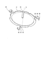
- FIG. 1 is a structural diagram of a stator constituting a three-phase AC motor.
- FIG. 2 is a perspective view showing the bus bar unit.
- FIG. 3 is a perspective view showing the first to fourth bus bars stacked.
- FIG. 4 is a perspective view showing the fourth bus bar.
- FIG. 5 is a perspective view showing a part of the fourth bus bar.
- FIG. 6 is a front view showing a part of the fourth bus bar.
- FIG. 7 is a view of the fourth bus bar as viewed from the direction of arrow A in FIG. 6.
- FIG. 8 is a perspective view showing the third bus bar.
- FIG. 9 is a perspective view showing a part of the third bus bar.
- FIG. 10 is a front view showing a part of the third bus bar.
- FIG. 11 is a view of the third bus bar as seen from the direction of arrow B in FIG.
- FIG. 12 is a perspective view showing the second bus bar.
- FIG. 13 is a perspective view showing a part of the second bus bar.
- FIG. 14 is a front view showing a part of the second bus bar.
- FIG. 15 is a view of the second bus bar as seen from the direction of arrow C in FIG.
- FIG. 16 is a perspective view showing the first bus bar.
- FIG. 17 is a perspective view showing a part of the first bus bar.
- FIG. 18 is a front view showing a part of the first bus bar.
- FIG. 19 is a view of the first bus bar as seen from the direction of arrow D in FIG.
- FIG. 20 is a side view showing the stacked first to fourth bus bars.
- FIG. 1 is a configuration diagram showing a stator 100 constituting a three-phase AC motor.
- a large number of teeth are formed on the annular stator core 112 held by the housing 111 so as to protrude to the inner peripheral side.
- a copper wire is wound around each tooth to form a U-phase coil 113, a V-phase coil 114, and a W-phase coil 115.
- a total of 18 U-phase coils 113, V-phase coils 114, and W-phase coils 115 are annularly arranged along the circumferential direction of the stator 100.
- Three sets of two U-phase coils 113, V-phase coils 114, and W-phase coils 115 are arranged in the circumferential direction of the stator 100 at intervals of 120 degrees. That is, two adjacent V-phase coils 114 are arranged next to two adjacent U-phase coils 113, and two adjacent W-phase coils 115 are arranged next to the two V-phase coils 114.
- the winding terminals 116 of adjacent coils of each phase are connected, and the remaining winding terminals 117 are connected to the bus bar unit 1 described later.
- FIG. 2 is a perspective view showing the bus bar unit 1.
- the axis O is the central axis of the bus bar unit 1 or the stator 100.
- axial direction means a direction in which the axis O extends
- radial direction means a radial direction around the axis O
- circumferential direction means a direction around the axis O.
- the bus bar unit 1 is provided concentrically with the stator 100 at the axial end portion of the stator 100.
- Stator 100 is arranged on the upper right side of bus bar unit 1 in FIG.
- the bus bar unit 1 includes a first bus bar 10, a second bus bar 20, and a third bus bar 30 corresponding to each phase, a fourth bus bar 40 for a neutral point that electrically connects neutral points, and first to first bus bars.
- Insulating resin 50 which accommodates the bus bars 10, 20, 30, 40 and electrically insulates the bus bars 10, 20, 30, 40 from each other and holds them in a predetermined position.
- Each bus bar 10, 20, 30, 40 and the insulating resin 50 are integrally formed by, for example, insert molding.
- the insulating resin 50 is fixed to the stator 100 by engaging a plurality of arms 51 protruding from the outer periphery thereof with an engaging portion (not shown) on the outer periphery of the stator 100.
- FIG. 3 is a perspective view showing a state in which the first to fourth bus bars 10, 20, 30, 40 are assembled.
- the bus bar unit 1 includes a first bus bar 10 connected to the W-phase coil 115, a second bus bar 20 connected to the U-phase coil 113, a third bus bar 30 connected to the V-phase coil 114, and a U-phase coil. 113, and a fourth bus bar 40 for a neutral point connected to all of the V-phase coil 114 and the W-phase coil 115.
- the first to fourth bus bars 10, 20, 30, 40 are arranged in order along the axial direction of the stator 100.
- the first bus bar 10 is provided at a position farthest from the stator 100.
- the fourth bus bar 40 is provided at a position closest to the stator 100.
- the first to fourth bus bars 10, 20, 30, 40 are respectively body portions 11, 21, 31, which are extended along the circumferential direction of the stator 100 so that the plate thickness direction coincides with the axial direction of the stator 100.
- connection portions 18, 28, 38, 48 connected to the winding terminals 117 of the coils 113, 114, 115.
- the extended portions 14, 24, 34, 44 are projected portions 13, 23, 33, 43. It is formed by bending.
- the main body portions 11, 21, 31, 41 are extended along the circumferential direction of the stator 100 so that the plate thickness direction thereof coincides with the axial direction of the stator 100. That is, the axial thickness of the main body portions 11, 21, 31, 41 is the plate thickness of the conductive material, and the radial width is the punching width of the conductive material.
- the first bus bar 10 corresponding to the W phase includes a W phase terminal 19 that extends in the axial direction of the stator 100 from the main body 11 to the outside of the insulating resin 50 and is connected to external wiring.
- the second bus bar 20 corresponding to the U phase includes a U phase terminal 29.
- the third bus bar 30 corresponding to the V phase similarly includes a V phase terminal 39.
- the bus bar unit 1 supplies a current supplied from a power source (not shown) to each phase coil 113, 114, 115 via each phase terminal 19, 29, 39 as an external terminal.
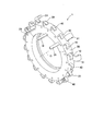
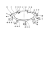
- FIG. 4 is a perspective view showing the fourth bus bar 40
- FIG. 5 is a perspective view showing a part of the fourth bus bar 40
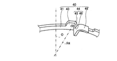
- FIG. 6 is a front view showing a part of the fourth bus bar 40
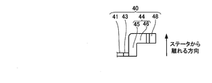
- FIG. FIG. 6 is a diagram when FIG. 6 is viewed from the direction of arrow A.
- the extended portion 44 is formed in a band shape extending in a crank shape, and extends in the axial direction of the stator 100 (the direction away from the stator 100), and the first axially extended portion 45. And a radially extending portion 46 extending in the radial direction of the stator 100.
- the punching widths of the first axially extending portion 45 and the radial extending portion 46 are formed to be equal to or greater than the punching width of the protruding portion 43, and a sufficient cross-sectional area of the conductive material is ensured.
- the extending portion 44 When the extending portion 44 is bent, the extending portion 44 held by a jig (not shown) is bent around the line R4 with respect to the protruding portion 43 held by another jig (not shown). .
- the extended portion 44 has a gap between the outer periphery 41 ⁇ / b> A of the main body portion 41. Thereby, it is avoided that the jig which clamps the extension part 44 interferes with the main-body part 41 at the time of a bending process.
- the extended portion 44 is bent at a right angle along a line R ⁇ b> 4 extending from the protruding portion 43 in the radial direction of the stator 100.
- the extending portion 44 is bent with respect to the protruding portion 43 in a direction away from the stator 100, and the connecting portion 48 is offset in a direction away from the main body portion 41 in the axial direction of the stator 100.
- the connecting portion 48 is a portion protruding from the radial tip of the radially extending portion 46, and this portion is bent into a hook shape.
- FIG. 8 is a perspective view showing the third bus bar 30
- FIG. 9 is a perspective view showing a part of the third bus bar 30
- FIG. 10 is a front view showing a part of the third bus bar 30, and
- FIG. 10 is a diagram when FIG. 10 is viewed from the direction of arrow B.
- the extending portion 34 is formed in a belt shape extending in a crank shape, and extends in the axial direction of the stator 100 (a direction away from the stator 100), and the first axially extending portion 35. And a radially extending portion 36 extending in the radial direction of the stator 100.
- the punching widths of the first axially extending portion 35 and the radial extending portion 36 are formed to be equal to or greater than the punching width of the protruding portion 33, and a sufficient cross-sectional area of the conductive material is ensured.
- the extending portion 34 held by a jig (not shown) is bent around the line R3 with respect to the protruding portion 33 held by another jig (not shown). .
- the outer periphery 31 ⁇ / b> A of the main body portion 31 extending along the extending portion 34 has an outer diameter smaller than the outer periphery 31 ⁇ / b> B adjacent thereto, and the extending portion 34 is between the outer periphery 31 ⁇ / b> A of the main body portion 31. Has a gap. Thereby, it is avoided that the jig which clamps the extension part 34 interferes with the main-body part 31 at the time of a bending process.
- the extended portion 34 is bent at a right angle along a line R ⁇ b> 3 extending from the protruding portion 33 in the radial direction of the stator 100.
- the extending portion 34 is bent in a direction away from the stator 100 with respect to the protruding portion 33, and the connecting portion 38 is offset in a direction away from the main body portion 31 in the axial direction of the stator 100.
- the length of the first axially extending portion 35 of the third bus bar 30 is larger than the length of the first axially extending portion 45 of the fourth bus bar 40 in the axial distance between the main body 31 and the main body 41.
- the portion 31 is formed to be shorter by the length including the plate thickness.
- the connecting portion 38 is a portion protruding from the radial tip of the radially extending portion 36, and this portion is bent into a hook shape.
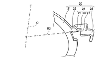
- FIG. 12 is a perspective view showing the second bus bar 20
- FIG. 13 is a perspective view showing a part of the second bus bar 20
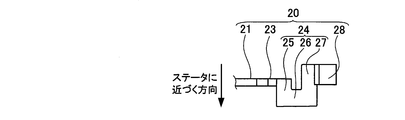
- FIG. 14 is a front view showing a part of the second bus bar 20
- FIG. FIG. 14 is a diagram when FIG. 14 is viewed from the direction of arrow C.
- the extending portion 24 is formed in a belt-like shape extending in a crank shape, and extends in the axial direction of the stator 100 (direction approaching the stator 100), and the first axially extending portion 25.
- the first axially extending portion 25 extends from the end of the radially extending portion 26 opposite to the first axially extending portion 25, and the radially extending portion 26 extending from the stator 100 in the radial direction of the stator 100.
- a second axially extending portion 27 extending in a parallel direction (a direction away from the stator 100).
- the punching widths of the first axially extending portion 25, the radial extending portion 26, and the second axially extending portion 27 are formed equal to or greater than the punching width of the protruding portion 23, and the cross-sectional area of the conductive material is sufficiently large Secured.
- the extending portion 24 held by a jig (not shown) is perpendicular to the protrusion 23 held by another jig (not shown) with the line R2 as the center. It can be bent.
- the outer periphery 21 ⁇ / b> A of the main body portion 21 extending along the extending portion 24 has an outer diameter smaller than the outer periphery 21 ⁇ / b> B adjacent thereto, and the extending portion 24 is between the outer periphery 21 ⁇ / b> A of the main body portion 21. Has a gap. Thereby, it is avoided that the jig which clamps the extension part 24 interferes with the main-body part 21 at the time of a bending process.
- the extending portion 24 is bent at a right angle along a line R ⁇ b> 2 extending from the protruding portion 23 in the radial direction of the stator 100.
- the extending portion 24 is bent in a direction approaching the stator 100 with respect to the protruding portion 23, but the second axially extending portion 27 extends in a direction away from the stator 100, so that the connecting portion 28 is the main body portion 21. Is hardly offset.
- the connecting portion 28 is a portion protruding from the radial tip of the radially extending portion 26, and this portion is bent into a hook shape.
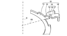
- FIG. 16 is a perspective view showing the first bus bar 10
- FIG. 17 is a perspective view showing a part of the first bus bar 10
- FIG. 18 is a front view showing a part of the first bus bar 10
- FIG. 19 is a diagram when FIG. 18 is viewed from the direction of arrow D.
- the extension part 14 is formed in a belt-like shape extending in a crank shape, and extends in the axial direction of the stator 100 (direction approaching the stator 100) and the first axial extension part 15. From the end of the radial extension portion 16 opposite to the first axial extension portion 15, the first axial extension portion 15 extends from the radial direction of the stator 100. And a second axially extending portion 17 extending in a parallel direction (a direction away from the stator 100).
- the punching widths of the first axially extending portion 15, the radial extending portion 16, and the second axially extending portion 17 are formed to be equal to or greater than the punching width of the protruding portion 13, and the cross-sectional area of the conductive material is sufficient. Secured.
- the extending portion 14 held by a jig (not shown) is perpendicular to the protruding portion 13 held by another jig (not shown) around the line R1. It can be bent.
- the outer periphery 11 ⁇ / b> A of the main body 11 extending along the extending portion 14 has an outer diameter smaller than the outer periphery 11 ⁇ / b> B adjacent thereto, and the extending portion 14 is between the outer periphery 11 ⁇ / b> A of the main body 11. Has a gap. Thereby, it is avoided that the jig which clamps the extension part 14 interferes with the main-body part 11 at the time of a bending process.
- the extending portion 14 is bent at a right angle along a line R ⁇ b> 1 extending from the protruding portion 13 in the radial direction of the stator 100.
- the extended portion 14 is bent in a direction approaching the stator 100 with respect to the protruding portion 13.
- the axial length of the second axially extending portion 17 is set to be equal to the axial length of the first axially extending portion 15. Thereby, the distance by which the connecting portion 18 is offset in the axial direction of the stator 100 with respect to the main body portion 11 becomes zero.
- the length of the first axially extending portion 15 of the first bus bar 10 is larger than the length of the first axially extending portion 25 of the second bus bar 20 in the axial distance between the main body 11 and the main body 21. It is formed longer by the length of the portion 21 plus the plate thickness. Thereby, the connecting portion 18 and the connecting portion 28 are arranged at the same position in the axial direction of the stator 100.
- the connecting portion 18 is a portion protruding from the radial tip of the radially extending portion 16, and this portion is bent into a hook shape.
- the hook-shaped connecting portions 18, 28, 38, and 48 are bent in the thickness direction and coupled to the winding terminals 117 of the phase coils 113, 114, and 115, respectively.
- connecting portions 18, 28, 38, and 48 are not limited to the shape that is bent into a hook shape as described above, and may have other shapes.
- FIG. 20 is a side view showing the state where the first to fourth bus bars 10, 20, 30, 40 are assembled, with the insulating resin 50 omitted.
- the first to fourth bus bars 10, 20, 30, and 40 are formed so that the connection portions 18, 28, 38, and 48 are arranged at the same position in the axial direction of the stator 100.
- a winding terminal 117 is coupled to the connecting portions 18, 28, 38, and 48 by a caulking process and a welding process.
- the connecting portions 18, 28, 38, 48 are arranged so as to fit in the same position in the axial direction as the main body portions 11, 21, and all the connecting portions 18, 28, 38 are between the first bus bar 10 and the fourth bus bar 40. , 48 can be accommodated, so that the bus bar unit 1 can be reduced in size.
- the first to fourth bus bars 10, 20, 30, and 40 are insert-molded in a state in which the protruding portions 13, 23, 33, and 43 are stacked so as to be arranged at equal intervals in the circumferential direction. Insert molding is performed by housing the first to fourth bus bars 10, 20, 30, 40 in a mold (not shown) and injecting an insulating resin 50 into the mold.
- the bus bar unit 1 in which the first to fourth bus bars 10, 20, 30, 40 and the insulating resin 50 are combined is removed from the mold to complete the bus bar unit 1 shown in FIG. .
- the bus bar unit 1 includes a plurality of bus bars 10, 20, 30, 40 to which winding terminals of a plurality of coils constituting the stator 100 are connected, and the plurality of bus bars 10, 20, 30, 40 are in the plate thickness direction.
- the stator 100 from the outer periphery of the main body parts 11, 21, 31, 41 extending along the circumferential direction of the stator 100 and the main body parts 11, 21, 31, 41 so as to coincide with the axial direction of the stator 100.
- stator 100 Projecting portions 13, 23, 33, 43 projecting outward in the direction, and extending portions 14, 24, 34, which are bent from the projecting portions 13, 23, 33, 43 and extend in the axial direction and the radial direction of the stator 100, 44 and connecting portions 18, 28, 38, and 48 that are provided at the distal ends of the extending portions 14, 24, 34, and 44 and that are connected to the coil winding terminals, and are provided with the extending portions 14, 24, 34, and 44.
- Is the stator Position of the connection portion 18,28,38,48 are defined according to the the length extending in the axial direction and the radial direction of 00.
- the extending portion 14 is bent in a direction approaching the stator 100 with respect to the protruding portion 13.
- the connecting portion 18 is disposed at a predetermined position in the axial direction of the stator 100.
- the bus bar 40 provided at a position closest to the stator 100 among the plurality of bus bars 10, 20, 30, 40, the extending portion 44 is bent in a direction away from the stator 100 with respect to the protruding portion 43, and the connecting portion 48. Is arranged at a predetermined position in the axial direction of the stator.
- the bus bars 10, 20, 30, 40 have a simple structure in which the extending portions 14, 24, 34, 44 are simply bent from the protruding portions 13, 23, 33, 43, and the extending portions 14, 24 are provided.
- , 34, 44 can be arranged at the same position in the axial direction of the stator 100 by adjusting the length in which the stator 100 extends in the axial direction of the stator 100. Therefore, for example, it is not necessary to use separate dedicated jigs (welding jigs) to connect the winding terminals 117 of the phase coils 113, 114, and 115 and the connecting portions 18, 28, 38, and 48, respectively. The cost of the product can be reduced.
- the bus bar unit 1 includes first to fourth bus bars 10, 20, 30, and 40 that are sequentially arranged in a direction in which the main body portions 11, 21, 31, and 41 approach from a position far from the stator 100.
- the extended portions 14 and 24 are bent in a direction approaching the stator 100 with respect to the projecting portions 13 and 23, and in the third and fourth bus bars 30 and 40, the extended portions are extended.
- the parts 34 and 44 are bent in a direction away from the stator 100 with respect to the projecting parts 33 and 43. Thereby, the connection parts 18, 28, 38, 48 can be aligned at the same position in the axial direction of the stator 100.
- the extending portions 14, 24, 34, 44 are bent along the lines R 1, R 2, R 3, R 4 extending in the radial direction of the stator 100 from the projecting portions 13, 23, 33, 43, thereby extending the extending portion 14. , 24, 34, 44 are obtained in a shape extending in the axial direction and the radial direction of the stator 100. Thereby, by adjusting the length of the extending portions 14, 24, 34, 44 extending in the axial direction of the stator 100 and the length extending in the radial direction of the stator 100, all the connecting portions 18, 28, 38, and 48 can be arranged at the same conditions in the axial direction and the radial direction of the stator 100.
- the extended portions 14, 24, 34, and 44 are formed by one-time bending with respect to the protruding portions 13, 23, 33, and 43, so that the number of times of bending can be reduced compared to a conventional bus bar. It is possible to simplify the structure and reduce the number of man-hours during manufacturing.
- the extended portions 14, 24, 34, 44 are bent from the projecting portions 13, 23, 33, 43 and are extended in the axial direction of the stator 100, and the first axially extended portions 15, 25, 35, 45 and radial extending portions 16, 26, 36, 46 extending in the radial direction of the stator 100 from the first axial extending portions 15, 25, 35, 45, and the first axial direction
- the extended portions 15, 25, 35, 45 and the radially extending portions 16, 26, 36, 46 are formed in a crank shape. Accordingly, the length in which the first axially extending portions 15, 25, 35, 45 are extended in the axial direction of the stator 100 and the radially extending portions 16, 26, 36, 46 are in the radial direction of the stator 100.
- all the connecting portions 18, 28, 38, 48 can be arranged at the same conditions in the axial direction and the radial direction of the stator 100.
- the extending portions 14 and 24 of the first and second bus bars 10 and 20 are connected to the stator 100 from the ends of the radial extending portions 16 and 26 opposite to the first axial extending portions 15 and 25.
- the first axially extending portions 15 and 25 extend in the axial direction
- the second axially extending portions 17 and 27 extend in the direction parallel to the first axially extending portions 15 and 25.
- the mounting portions 16 and 26 and the second axially extending portions 17 and 27 form a crank shape.
- the connecting portions 18 and 28 are connected to the main body portion 11 according to the length of the first axially extending portions 15 and 25 and the second axially extending portions 17 and 27 extending in the axial direction of the stator 100.
- the distance offset in the axial direction from 21 can be set small.
- connection portions 18, 28, 38, 48 are arranged in the same circumferential shape. Therefore, since the connection parts 18, 28, 38, and 48 are arrange
- the first to fourth bus bars 10, 20, 30, and 40 are illustrated as having an annular shape, but may be in an arc shape.
- bus bars 10, 20, 30, 40 are provided.
- the configuration may include three or less or five or more types of bus bars depending on the type of motor.
- the three-phase alternating current motor which has 18 coils 113, 114, 115 was illustrated, the number of coils is not limited to this.
- first to fourth bus bars 10, 20, 30, 40 are arranged in the order of the first bus bar 10, the second bus bar 20, the third bus bar 30, and the fourth bus bar 40 in the bus bar unit 1. Other arrangement orders may be used.
- bus bar unit is connected to a motor that generates power by electric power.
- the bus bar unit may be applied to a generator that generates electric power by power.
Landscapes
- Engineering & Computer Science (AREA)
- Power Engineering (AREA)
- Insulation, Fastening Of Motor, Generator Windings (AREA)
- Manufacture Of Motors, Generators (AREA)
Abstract
Description
Claims (6)
- ステータを構成する複数のコイルの巻線端末が接続される複数のバスバーを備え、前記複数のバスバーが前記ステータの軸方向に沿って配置されるバスバーユニットであって、
前記複数のバスバーは、板厚方向が前記ステータの軸方向に一致するように前記ステータの周方向に沿って延設される本体部と、前記本体部の外周から前記ステータの径方向外側に突出する突出部と、前記突出部から折り曲げられ前記ステータの軸方向及び径方向に延設される延設部と、前記延設部の先端に設けられ前記コイルの巻線端末に接続する接続部と、を備え、
前記延設部が前記ステータの軸方向及び径方向に延設される長さに応じて前記接続部の位置が規定される、
バスバーユニット。 - 請求項1に記載のバスバーユニットであって、
前記複数のバスバーのうち前記ステータから最も遠い位置に設けられる前記バスバーでは、前記延設部が前記突出部に対して前記ステータに近づく方向に折り曲げられ、前記接続部が前記ステータの軸方向の所定位置に配置され、
前記複数のバスバーのうち前記ステータに最も近い位置に設けられる前記バスバーでは、前記延設部が前記突出部に対して前記ステータから離れる方向に折り曲げられ、前記接続部が前記ステータの軸方向の前記所定位置に配置される、
バスバーユニット。 - 請求項1に記載のバスバーユニットであって、
前記複数のバスバーは、前記ステータに対して遠い位置から近づく方向に順に並ぶ第1~第4の前記バスバーを有し、
前記第1、第2のバスバーでは、前記延設部が前記突出部に対して前記ステータに近づく方向に折り曲げられ、
前記第3、第4のバスバーでは、前記延設部が前記突出部に対して前記ステータから離れる方向に折り曲げられる、
バスバーユニット。 - 請求項3に記載のバスバーユニットであって、
前記延設部は、前記突出部から折り曲げられて前記ステータの軸方向に延設される第1軸方向延設部と、前記第1軸方向延設部から前記ステータの径方向に延設される径方向延設部と、を有し、第1軸方向延設部及び径方向延設部によってクランク状に形成される、
バスバーユニット。 - 請求項4に記載のバスバーユニットであって、
前記第1、第2バスバーの前記延設部は、前記径方向延設部の前記第1軸方向延設部とは反対側の端部から前記ステータの軸方向に前記第1軸方向延設部と平行方向に延設される第2軸方向延設部を有し、前記第1軸方向延設部、前記径方向延設部及び第2軸方向延設部によってクランク状に形成される、
バスバーユニット。 - 請求項1に記載のバスバーユニットであって、
前記接続部は、それぞれ同一円周状に配置される、
バスバーユニット。
Priority Applications (2)
| Application Number | Priority Date | Filing Date | Title |
|---|---|---|---|
| US14/772,025 US9917483B2 (en) | 2013-03-08 | 2014-01-27 | Bus bar unit |
| CN201480010659.3A CN105027392B (zh) | 2013-03-08 | 2014-01-27 | 汇流条单元 |
Applications Claiming Priority (2)
| Application Number | Priority Date | Filing Date | Title |
|---|---|---|---|
| JP2013047234A JP6286129B2 (ja) | 2013-03-08 | 2013-03-08 | バスバーユニット |
| JP2013-047234 | 2013-03-08 |
Publications (1)
| Publication Number | Publication Date |
|---|---|
| WO2014136495A1 true WO2014136495A1 (ja) | 2014-09-12 |
Family
ID=51491021
Family Applications (1)
| Application Number | Title | Priority Date | Filing Date |
|---|---|---|---|
| PCT/JP2014/051634 Ceased WO2014136495A1 (ja) | 2013-03-08 | 2014-01-27 | バスバーユニット |
Country Status (4)
| Country | Link |
|---|---|
| US (1) | US9917483B2 (ja) |
| JP (1) | JP6286129B2 (ja) |
| CN (1) | CN105027392B (ja) |
| WO (1) | WO2014136495A1 (ja) |
Cited By (3)
| Publication number | Priority date | Publication date | Assignee | Title |
|---|---|---|---|---|
| WO2017199736A1 (ja) * | 2016-05-16 | 2017-11-23 | Kyb株式会社 | バスバーユニット及び回転電機 |
| DE102017208353A1 (de) * | 2017-05-18 | 2018-11-22 | Robert Bosch Gmbh | Kontaktierung von Wickeldraht |
| US20220320936A1 (en) * | 2019-06-06 | 2022-10-06 | Nidec Corporation | Stator and motor including the same |
Families Citing this family (26)
| Publication number | Priority date | Publication date | Assignee | Title |
|---|---|---|---|---|
| KR102625432B1 (ko) * | 2016-01-08 | 2024-01-16 | 엘지이노텍 주식회사 | 버스바 터미널, 버스바, 모터 및 이를 포함하는 차량 |
| JP6771537B2 (ja) * | 2016-02-24 | 2020-10-21 | 株式会社日立製作所 | アキシャルギャップ型回転電機 |
| CN108886307B (zh) * | 2016-03-17 | 2020-08-18 | 本田技研工业株式会社 | 夹具、定子制造装置以及定子的制造方法 |
| KR102697649B1 (ko) * | 2016-04-27 | 2024-08-23 | 엘지이노텍 주식회사 | 파워 터미널 및 이를 포함하는 모터 |
| DE102017216074A1 (de) | 2016-10-14 | 2018-04-19 | Robert Bosch Gmbh | Elektromotor mit einem Klemmelement |
| DE202016008549U1 (de) * | 2016-11-04 | 2018-07-31 | Nidec Corporation | Sammelschieneneinheit für einen Elektromotor |
| DE112017005921T5 (de) | 2016-11-23 | 2019-08-29 | Nidec Corporation | Motor und elektrische servolenkvorrichtung |
| DE102016123479A1 (de) | 2016-12-05 | 2018-06-07 | Nidec Corporation | Sammelschieneneinheit für einen Stator eines Elektromotors |
| DE102016224542A1 (de) * | 2016-12-08 | 2018-06-14 | Bayerische Motoren Werke Aktiengesellschaft | Schaltring für einen Stator einer elektrischen Rotationsmaschine |
| CN107070036A (zh) * | 2017-04-25 | 2017-08-18 | 余姚市爱优特电机有限公司 | 一种电机定子绕组连接结构及其连接方法 |
| JP7031441B2 (ja) * | 2017-09-28 | 2022-03-08 | 日本電産株式会社 | モータ |
| JP7205479B2 (ja) * | 2017-09-28 | 2023-01-17 | 日本電産株式会社 | モータおよびモータの製造方法 |
| JPWO2019064878A1 (ja) * | 2017-09-29 | 2020-10-22 | 日本電産株式会社 | バスバーユニット、モータ |
| DE102018202408A1 (de) * | 2018-02-16 | 2019-08-22 | Bühler Motor GmbH | Stator mit einer wicklungsverschaltung |
| DE102018216463A1 (de) * | 2018-09-26 | 2020-03-26 | Zf Friedrichshafen Ag | Verschaltungsanordnung für eine elektrische Maschine |
| JP2020088877A (ja) * | 2018-11-14 | 2020-06-04 | 日本電産株式会社 | バスバーユニット、モータ |
| DE102018219539A1 (de) * | 2018-11-15 | 2020-05-20 | Zf Friedrichshafen Ag | Verschaltungsanordnung für eine elektrische Maschine |
| US11438680B2 (en) * | 2019-02-28 | 2022-09-06 | Murata Manufacturing Co., Ltd. | Transducer for converting between electrical energy and mechanical energy |
| WO2021031783A1 (zh) * | 2019-08-20 | 2021-02-25 | 安徽威灵汽车部件有限公司 | 汇流排、汇流排主体、电机、电动助力转向系统和车辆 |
| CN112421274B (zh) * | 2019-08-20 | 2026-04-03 | 安徽威灵汽车部件有限公司 | 汇流排、电机及车辆 |
| EP3800349B1 (en) * | 2019-10-02 | 2022-08-03 | Siemens Gamesa Renewable Energy A/S | Busbar arrangement for wind turbine generator |
| TWI699075B (zh) | 2019-10-14 | 2020-07-11 | 群光電能科技股份有限公司 | 馬達定子結線裝置 |
| JP6945611B2 (ja) * | 2019-12-17 | 2021-10-06 | 三菱電機株式会社 | 回転電機の固定子 |
| CN113783048B (zh) * | 2020-06-09 | 2025-04-29 | 安徽威灵汽车部件有限公司 | 汇流排、电机、水泵和车辆 |
| KR20220103391A (ko) * | 2021-01-15 | 2022-07-22 | 엘지이노텍 주식회사 | 모터 |
| CN117856499A (zh) | 2022-09-30 | 2024-04-09 | 日本电产株式会社 | 马达 |
Citations (2)
| Publication number | Priority date | Publication date | Assignee | Title |
|---|---|---|---|---|
| JP2009290921A (ja) * | 2008-05-27 | 2009-12-10 | Mitsuba Corp | ブラシレスモータ |
| JP2013042633A (ja) * | 2011-08-19 | 2013-02-28 | Nippon Densan Corp | モータ |
Family Cites Families (4)
| Publication number | Priority date | Publication date | Assignee | Title |
|---|---|---|---|---|
| JPH06233483A (ja) | 1993-01-29 | 1994-08-19 | Honda Motor Co Ltd | ステータに於けるコイル巻線の結線構造 |
| JP5703604B2 (ja) * | 2010-03-03 | 2015-04-22 | 日本電産株式会社 | バスバーユニット及びモータ |
| JP5534598B2 (ja) * | 2010-07-22 | 2014-07-02 | 株式会社ケーヒン | 回転電機 |
| EP2562915B1 (en) | 2011-08-24 | 2015-05-20 | Sumitomo Wiring Systems, Ltd. | Central power supply member and method of assembling it |
-
2013
- 2013-03-08 JP JP2013047234A patent/JP6286129B2/ja active Active
-
2014
- 2014-01-27 CN CN201480010659.3A patent/CN105027392B/zh not_active Expired - Fee Related
- 2014-01-27 US US14/772,025 patent/US9917483B2/en not_active Expired - Fee Related
- 2014-01-27 WO PCT/JP2014/051634 patent/WO2014136495A1/ja not_active Ceased
Patent Citations (2)
| Publication number | Priority date | Publication date | Assignee | Title |
|---|---|---|---|---|
| JP2009290921A (ja) * | 2008-05-27 | 2009-12-10 | Mitsuba Corp | ブラシレスモータ |
| JP2013042633A (ja) * | 2011-08-19 | 2013-02-28 | Nippon Densan Corp | モータ |
Cited By (3)
| Publication number | Priority date | Publication date | Assignee | Title |
|---|---|---|---|---|
| WO2017199736A1 (ja) * | 2016-05-16 | 2017-11-23 | Kyb株式会社 | バスバーユニット及び回転電機 |
| DE102017208353A1 (de) * | 2017-05-18 | 2018-11-22 | Robert Bosch Gmbh | Kontaktierung von Wickeldraht |
| US20220320936A1 (en) * | 2019-06-06 | 2022-10-06 | Nidec Corporation | Stator and motor including the same |
Also Published As
| Publication number | Publication date |
|---|---|
| US20160013691A1 (en) | 2016-01-14 |
| JP2014176207A (ja) | 2014-09-22 |
| JP6286129B2 (ja) | 2018-02-28 |
| CN105027392A (zh) | 2015-11-04 |
| US9917483B2 (en) | 2018-03-13 |
| CN105027392B (zh) | 2018-10-09 |
Similar Documents
| Publication | Publication Date | Title |
|---|---|---|
| JP6286129B2 (ja) | バスバーユニット | |
| JP6053001B2 (ja) | バスバーユニット | |
| JP4465395B2 (ja) | 回転電機の集配電リング | |
| US10615656B2 (en) | Bus bar structure for a motor | |
| JP6190599B2 (ja) | バスバーユニットの製造方法 | |
| US8836186B2 (en) | Bus bar device, stator, motor and manufacturing method for stator | |
| US8497618B2 (en) | Stator for rotatry electrical machine including an insulating bobbin | |
| JP6465203B2 (ja) | ステータ | |
| JP4684023B2 (ja) | 車両用薄型ブラシレスモータの集中配電部材 | |
| JP5377702B2 (ja) | 回転電機およびその製造方法 | |
| US9887601B2 (en) | Stator of rotary electric machine | |
| US12166386B2 (en) | Stator, motor, and method for manufacturing stator | |
| US20220320937A1 (en) | Busbar unit, stator, and method for manufacturing busbar unit | |
| US20190013710A1 (en) | Rotary Electric Machine | |
| JP2007174869A (ja) | インシュレータ、ステータアセンブリ、セグメントステータ、及び回転電機用ステータ | |
| US20170214287A1 (en) | Stator for rotating electric machine and rotating electric machine including the stator | |
| JP5818771B2 (ja) | 回転電機のステータ | |
| JP5963928B1 (ja) | 回転電機の結線ユニット | |
| JP4465396B2 (ja) | 回転電機の配電接続構造および回転電機の配電接続構造の製造方法 | |
| JP2019037103A (ja) | ステータ及びモータ | |
| WO2014157621A1 (ja) | ステータの構造 | |
| JP6086243B2 (ja) | モータの集中配電部材 | |
| JP7216254B2 (ja) | ステータ | |
| JP5144180B2 (ja) | ステータの中点連結構造 | |
| JP2015192457A (ja) | 回転電機用ステータの端子台 |
Legal Events
| Date | Code | Title | Description |
|---|---|---|---|
| WWE | Wipo information: entry into national phase |
Ref document number: 201480010659.3 Country of ref document: CN |
|
| 121 | Ep: the epo has been informed by wipo that ep was designated in this application |
Ref document number: 14760129 Country of ref document: EP Kind code of ref document: A1 |
|
| WWE | Wipo information: entry into national phase |
Ref document number: 14772025 Country of ref document: US |
|
| NENP | Non-entry into the national phase |
Ref country code: DE |
|
| 122 | Ep: pct application non-entry in european phase |
Ref document number: 14760129 Country of ref document: EP Kind code of ref document: A1 |