WO2014136450A1 - 車両用空調装置 - Google Patents
車両用空調装置 Download PDFInfo
- Publication number
- WO2014136450A1 WO2014136450A1 PCT/JP2014/001213 JP2014001213W WO2014136450A1 WO 2014136450 A1 WO2014136450 A1 WO 2014136450A1 JP 2014001213 W JP2014001213 W JP 2014001213W WO 2014136450 A1 WO2014136450 A1 WO 2014136450A1
- Authority
- WO
- WIPO (PCT)
- Prior art keywords
- refrigerant
- cycle
- air conditioner
- heat
- compressor
- Prior art date
Links
Images


Classifications
-
- B—PERFORMING OPERATIONS; TRANSPORTING
- B60—VEHICLES IN GENERAL
- B60H—ARRANGEMENTS OF HEATING, COOLING, VENTILATING OR OTHER AIR-TREATING DEVICES SPECIALLY ADAPTED FOR PASSENGER OR GOODS SPACES OF VEHICLES
- B60H1/00—Heating, cooling or ventilating [HVAC] devices
- B60H1/00007—Combined heating, ventilating, or cooling devices
-
- B—PERFORMING OPERATIONS; TRANSPORTING
- B60—VEHICLES IN GENERAL
- B60H—ARRANGEMENTS OF HEATING, COOLING, VENTILATING OR OTHER AIR-TREATING DEVICES SPECIALLY ADAPTED FOR PASSENGER OR GOODS SPACES OF VEHICLES
- B60H1/00—Heating, cooling or ventilating [HVAC] devices
- B60H1/00642—Control systems or circuits; Control members or indication devices for heating, cooling or ventilating devices
- B60H1/00814—Control systems or circuits characterised by their output, for controlling particular components of the heating, cooling or ventilating installation
- B60H1/00878—Control systems or circuits characterised by their output, for controlling particular components of the heating, cooling or ventilating installation the components being temperature regulating devices
- B60H1/00899—Controlling the flow of liquid in a heat pump system
- B60H1/00921—Controlling the flow of liquid in a heat pump system where the flow direction of the refrigerant does not change and there is an extra subcondenser, e.g. in an air duct
-
- B—PERFORMING OPERATIONS; TRANSPORTING
- B60—VEHICLES IN GENERAL
- B60H—ARRANGEMENTS OF HEATING, COOLING, VENTILATING OR OTHER AIR-TREATING DEVICES SPECIALLY ADAPTED FOR PASSENGER OR GOODS SPACES OF VEHICLES
- B60H1/00—Heating, cooling or ventilating [HVAC] devices
- B60H1/32—Cooling devices
- B60H1/3204—Cooling devices using compression
- B60H1/3205—Control means therefor
- B60H1/3213—Control means therefor for increasing the efficiency in a vehicle heat pump
-
- B—PERFORMING OPERATIONS; TRANSPORTING
- B60—VEHICLES IN GENERAL
- B60H—ARRANGEMENTS OF HEATING, COOLING, VENTILATING OR OTHER AIR-TREATING DEVICES SPECIALLY ADAPTED FOR PASSENGER OR GOODS SPACES OF VEHICLES
- B60H1/00—Heating, cooling or ventilating [HVAC] devices
- B60H1/32—Cooling devices
- B60H1/3204—Cooling devices using compression
- B60H1/3228—Cooling devices using compression characterised by refrigerant circuit configurations
- B60H1/32284—Cooling devices using compression characterised by refrigerant circuit configurations comprising two or more secondary circuits, e.g. at evaporator and condenser side
-
- B—PERFORMING OPERATIONS; TRANSPORTING
- B60—VEHICLES IN GENERAL
- B60H—ARRANGEMENTS OF HEATING, COOLING, VENTILATING OR OTHER AIR-TREATING DEVICES SPECIALLY ADAPTED FOR PASSENGER OR GOODS SPACES OF VEHICLES
- B60H1/00—Heating, cooling or ventilating [HVAC] devices
- B60H1/00642—Control systems or circuits; Control members or indication devices for heating, cooling or ventilating devices
- B60H1/00814—Control systems or circuits characterised by their output, for controlling particular components of the heating, cooling or ventilating installation
- B60H1/00878—Control systems or circuits characterised by their output, for controlling particular components of the heating, cooling or ventilating installation the components being temperature regulating devices
- B60H2001/00928—Control systems or circuits characterised by their output, for controlling particular components of the heating, cooling or ventilating installation the components being temperature regulating devices comprising a secondary circuit
-
- F—MECHANICAL ENGINEERING; LIGHTING; HEATING; WEAPONS; BLASTING
- F25—REFRIGERATION OR COOLING; COMBINED HEATING AND REFRIGERATION SYSTEMS; HEAT PUMP SYSTEMS; MANUFACTURE OR STORAGE OF ICE; LIQUEFACTION SOLIDIFICATION OF GASES
- F25B—REFRIGERATION MACHINES, PLANTS OR SYSTEMS; COMBINED HEATING AND REFRIGERATION SYSTEMS; HEAT PUMP SYSTEMS
- F25B5/00—Compression machines, plants or systems, with several evaporator circuits, e.g. for varying refrigerating capacity
- F25B5/02—Compression machines, plants or systems, with several evaporator circuits, e.g. for varying refrigerating capacity arranged in parallel
Definitions
- the present invention relates to a vehicle air conditioner.
- Patent Document 1 a vehicle air conditioner that uses a heat pump to cool and heat the vehicle interior has been proposed (see, for example, Patent Document 1).
- This type of problem is not limited to the vehicle air conditioner disclosed in Patent Document 1, and may occur when the first refrigerant cycle and the second refrigerant cycle are provided in various patterns and a part of the refrigerant passage is shared. .
- An object of the present invention is to provide a vehicle air conditioner that eliminates a decrease in the refrigerant amount in the first refrigerant cycle and suppresses a decrease in air conditioning performance.
- An air conditioner for a vehicle is a path for circulating a refrigerant, a first refrigerant cycle forming a first heat pump cycle, and a path for circulating the refrigerant, the first heat pump cycle,
- the second refrigerant cycle that forms a different second heat pump cycle and shares a part of the path with the first refrigerant cycle, the low-temperature low-pressure refrigerant included in the first refrigerant cycle, and the coolant of the heating member of the vehicle
- a first water refrigerant heat exchanger that vaporizes the refrigerant by exchanging heat between them, a flow rate adjusting means for adjusting a flow rate of the coolant flowing through the heat generating member and the first water refrigerant heat exchanger, and the second Detecting means for detecting a decrease in the refrigerant amount in the first refrigerant cycle due to the inflow of refrigerant into the refrigerant cycle; and when detecting a decrease in the refrigerant amount
- the present invention it is possible to eliminate the decrease in the amount of refrigerant in the first refrigerant cycle and suppress the deterioration in air conditioning performance.
- FIG. 4 is a flowchart showing the sleeping refrigerant recovery operation procedure shown in FIG. Flow chart showing the normal operation procedure shown in FIG.
- FIG. 4 is a flowchart showing the sleeping refrigerant recovery operation procedure shown in FIG. The figure which showed the state of the stagnation of the refrigerant together with the discharge pressure and the suction pressure of the refrigerant
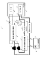
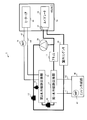
- FIG. 1 is a configuration diagram illustrating a vehicle air conditioner according to Embodiment 1 of the present invention.
- the vehicle air conditioner 1 is a device that is mounted on a vehicle having an engine (internal combustion engine) and performs heating, dehumidification, and cooling of the passenger compartment.
- the vehicle air conditioner 1 includes a first water refrigerant heat exchanger 11, a second water refrigerant heat exchanger 12, an on-off valve 13, an expansion valve 14 with a solenoid valve, a second water pump 16, an accumulator 17, an expansion valve 37, and a compressor. (Compressor) 38, an outdoor condenser 39, an engine cooling unit 40, a heater core 44, an evaporator 48, and a coolant pipe and a refrigerant pipe that connect them.
- the heater core 44 and the evaporator 48 are disposed in an intake passage of an HVAC (Heating, Ventilation, and Air Conditioning) 70.
- the HVAC 70 is provided with a blower fan (not shown) through which intake air flows.
- the first water refrigerant heat exchanger 11 has a passage through which a low-temperature and low-pressure refrigerant flows and a passage through which a coolant flows, and performs heat exchange between the refrigerant and the coolant.
- the first water refrigerant heat exchanger 11 is supplied with a low-temperature and low-pressure refrigerant in a predetermined operation mode, and the coolant is circulated between the engine cooling unit 40 via the pipes h1 and h2. To move heat from the coolant to the low temperature and low pressure refrigerant.
- the second water refrigerant heat exchanger 12 has a passage through which a high-temperature and high-pressure refrigerant flows and a passage through which a cooling liquid flows, and performs heat exchange between the refrigerant and the cooling liquid.
- a coolant is circulated between the heater core 44 and the heat from the high-temperature and high-pressure refrigerant to the coolant in a predetermined operation mode.
- a second water pump 16 is provided on one of the two pipes h3 and h4 connected to the coolant inlet and the outlet of the second water refrigerant heat exchanger 12, respectively. These two pipes h3 and h4 are connected to the heater core 44.
- the second water pump 16 is a pump capable of circulating the coolant between the second water refrigerant heat exchanger 12 and the heater core 44 by, for example, electrical driving.
- the refrigerant pipe j1 connected to the refrigerant inlet of the second water refrigerant heat exchanger 12 is connected to the discharge port of the compressor 38.
- the refrigerant pipe j2 connected to the refrigerant outlet of the second water refrigerant heat exchanger 12 is branched into two.
- One of the branched refrigerant pipes is connected to the refrigerant inlet of the outdoor capacitor 39 via the on-off valve 13.
- the other of the branched refrigerant pipes j3 is connected to the refrigerant inlet of the first water refrigerant heat exchanger 11 via an expansion valve 14 with a solenoid valve.
- the refrigerant pipe j4 connected to the refrigerant outlet of the first water refrigerant heat exchanger 11 is connected to the refrigerant inlet of the compressor 38 via the accumulator 17.
- the refrigerant pipe of the evaporator 48 is also joined to the refrigerant suction port of the compressor 38.
- the on-off valve 13 is a valve that switches between opening and closing of the refrigerant pipe, for example, by electrical control.
- the expansion valve 14 with a solenoid valve is a valve that functions as an expansion valve when the refrigerant pipe is opened and closed by, for example, electrical control and is opened.
- the accumulator 17 separates the vaporized refrigerant that has passed through the first water refrigerant heat exchanger 11 and the non-vaporized refrigerant, and sends only the vaporized refrigerant to the compressor 38.
- the compressor 38 is driven by electricity to compress the sucked refrigerant into a high temperature and high pressure and discharge it.
- the compressed refrigerant is sent to the second water refrigerant heat exchanger 12.
- the engine cooling unit 40 includes a water jacket for flowing a coolant around the engine and a first water pump 42 for flowing the coolant to the water jacket and the first water-refrigerant heat exchanger 11, and the coolant flowing to the water jacket To release heat from the engine.
- the first water pump 42 is rotated by, for example, engine power.
- the heater core 44 is a device that exchanges heat between the coolant and air, and is disposed in the intake passage of the HVAC 70 that supplies air into the passenger compartment.
- the heater core 44 is supplied with a heated coolant and releases heat to the intake air that is sent into the passenger compartment during the heating operation.
- the evaporator 48 is a device that exchanges heat between the low-temperature and low-pressure refrigerant and the air, and is disposed in the intake passage of the HVAC 70.
- the evaporator 48 is supplied with a low-temperature and low-pressure refrigerant during the cooling operation or the dehumidifying operation, and cools the intake air supplied into the passenger compartment.
- the expansion valve 37 expands the high-pressure refrigerant to a low temperature and low pressure and discharges it to the evaporator 48.
- the expansion valve 37 is disposed in the vicinity of the evaporator 48.
- the outdoor condenser 39 has a passage through which the refrigerant flows and a passage through which the air flows.
- the outdoor condenser 39 is disposed near the top of the vehicle in the engine room and exchanges heat between the refrigerant and the outside air.
- a high-temperature and high-pressure refrigerant is passed through the outdoor condenser 39 in the cooling mode and the dehumidifying mode, and heat is discharged from the refrigerant to the outside air. Outside air is blown onto the outdoor condenser 39 by, for example, a fan.
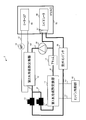
- FIG. 2 is a diagram for explaining the operation in the heating mode in the vehicle air conditioner 1.
- the on-off valve 13 is closed, the expansion valve 14 with a solenoid valve is opened, and the second water pump 16 is turned on.
- the compressor 38 when the compressor 38 is operated, the refrigerant passes through the second water refrigerant heat exchanger 12, the expansion valve 14 with a solenoid valve, the first water refrigerant heat exchanger 11, the accumulator 17, and the compressor 38 in this order. It flows cyclically. This path is called a heating refrigerant cycle (corresponding to a first refrigerant cycle).
- the high-temperature and high-pressure refrigerant compressed by the compressor 38 releases heat to the coolant in the second water refrigerant heat exchanger 12 and condenses. Further, the low-temperature and low-pressure refrigerant expanded by the expansion valve 14 with a solenoid valve is vaporized by absorbing heat from the coolant in the first water refrigerant heat exchanger 11.
- Coolant flows in two paths and flows independently.
- the coolant in the first path flows cyclically between the engine cooling unit 40 and the first water refrigerant heat exchanger 11.
- the coolant in the first path cools the engine in the engine cooling unit 40 and releases heat to the low-temperature and low-pressure refrigerant in the first water-refrigerant heat exchanger 11.
- the coolant in the second path circulates between the second water refrigerant heat exchanger 12 and the heater core 44 by the second water pump 16.
- the coolant in the second path absorbs heat from the high-temperature and high-pressure refrigerant in the second water-refrigerant heat exchanger 12 and releases heat to the intake air that is sent into the passenger compartment in the heater core 44.
- the vehicle air conditioner 1 has a high temperature because the refrigerant saturation pressure of the outdoor condenser 39 installed in a low temperature environment decreases at a low outdoor temperature (for example, ⁇ 20 ° C.).
- the pressure of the outdoor condenser 39 is lower than that of the first water-refrigerant heat exchanger 11, and the refrigerant pipe (cooling refrigerant cycle (second refrigerant cycle) of the evaporator 48 connected to the heating refrigerant cycle at the refrigerant inlet of the compressor 38 is joined.
- the refrigerant flows into a part of The refrigerant that has flowed into the refrigerant pipe of the evaporator 48 stagnates in the outdoor condenser 39.
- a check valve is not provided in the vehicle air conditioner 1 and an air conditioner ECU (Electronic Control Unit) controls each part in the apparatus to collect the sleeping refrigerant.
- ECU Electronic Control Unit
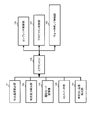
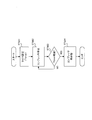
- FIG. 3 is a block diagram showing a functional configuration around the air conditioner ECU in the vehicle air conditioner 1 according to Embodiment 1 of the present invention.
- the discharge temperature detection unit 101 detects the temperature of the refrigerant discharged from the compressor 38 and notifies the air conditioner ECU 109 of the detected temperature of the refrigerant.
- the discharge pressure detection unit 102 detects the pressure of the refrigerant discharged from the compressor 38 and notifies the air conditioner ECU 109 of the detected refrigerant pressure.
- the operation mode storage unit 103 stores the current operation mode of the vehicle air conditioner 1, that is, the heating mode, the cooling mode, the dehumidifying mode, and the like, and notifies the air conditioner ECU 109 of the current operation mode.
- the AC switch unit 104 is a switch for the user to control the air conditioning in the passenger compartment, receives instructions from the user such as on / off of the air conditioner, temperature, and air volume, and outputs the instructions from the user to the air conditioner ECU 109.
- the blower temperature detection unit 105 exchanges heat with the heater core 44 or the evaporator 48 to detect the blowout temperature of the intake air supplied to the passenger compartment, and notifies the air conditioner ECU 109 of the detected blowout temperature.
- the compressor control unit 106 controls the rotation speed of the compressor 38 based on the control of the air conditioner ECU 109 and notifies the air conditioner ECU 109 of the rotation speed of the compressor 38 and the like.
- the blower fan control unit 107 controls the rotational speed of the blower fan in the HVAC 70 based on the control of the air conditioner ECU 109, and notifies the air conditioner ECU 109 of the rotational speed of the blower fan and the like.
- the water pump control unit 108 controls the number of rotations of the first water pump 42 and the second water pump 16 in the engine cooling unit 40 based on the control of the air conditioner ECU 109, and the first water pump 42 and the second water pump 16 are also controlled.
- the air conditioner ECU 109 is notified of the rotational speed of the pump 16 and the like.
- the air conditioner ECU 109 determines whether or not stagnation has occurred in the cooling refrigerant cycle during the heating mode based on information from the various detection units, switches, and various control units. The stagnation refrigerant recovery operation for recovery to the heating refrigerant cycle is performed, and the normal operation is performed when the stagnation does not occur. The detailed operation of the air conditioner ECU 109 will be described later.
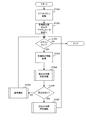
- step (hereinafter abbreviated as “ST”) 201 the air conditioner EUC 109 is activated upon receiving an ignition ON operation.
- step (ST 202) the air conditioner ECU 109 opens and closes various doors provided in the various detection units and the HVAC 70. Initialize the actuator to perform.
- the air conditioner ECU 109 acquires detection information from various detection units, and in ST205, a sleeping refrigerant determination process is performed. Details of the sleeping refrigerant determination process will be described later.
- the air conditioner ECU 109 determines whether or not the refrigerant has stagnation as a result of the stagnation refrigerant determination process in ST205. If the stagnation has occurred (YES), the process proceeds to ST207 and the stagnation has occurred. If not (NO), the process proceeds to ST208.
- the air conditioner ECU 109 performs the sleep refrigerant recovery operation and returns to ST203. Details of the sleeping refrigerant recovery operation will be described later.
- the air conditioner ECU 109 performs normal operation and returns to ST203. Details of the normal operation will be described later.
- the air conditioner ECU 109 determines whether or not the rotation speed of the compressor 38 is changed. If there is no change (YES), the process proceeds to ST302, and if there is a change (NO), ST308. Migrate to
- the air conditioner ECU 109 determines whether or not there is a change in the rotation speed (air volume) of the blower fan in the HVAC 70. If there is no change (YES), the process proceeds to ST303, and if there is a change (NO). Moves to ST308.
- the air conditioner ECU 109 determines whether or not the operation mode is changed. If there is no change (YES), the process proceeds to ST304, and if there is a change (NO), the process proceeds to ST308.
- the air conditioner ECU 109 determines whether or not the rotational speed of the second water pump 16 is changed. If there is no change (YES), the process proceeds to ST305, and if there is a change (NO), ST308. Migrate to Note that the procedures of ST301 to ST304 may be performed in any order, or may be performed simultaneously.
- the air conditioner ECU 109 determines whether or not the stagnation determination timer is set. If it is set (YES), the process proceeds to ST310, and if it is not set (NO), the process proceeds to ST306. .
- the air conditioner ECU 109 acquires the refrigerant discharge temperature Td and the coolant outlet water temperature Tsc_out in the second water refrigerant heat exchanger 12, and stores them as reference values.
- the stagnation determination timer is set.
- the set value Twait seconds is set, and the sleeping refrigerant determination process is terminated.
- the air conditioner ECU 109 deletes the stagnation determination timer set in ST307, and in ST309, determines that the refrigerant has not stagnation and ends the stagnation refrigerant determination process.
- the air conditioner ECU 109 determines whether the stagnation determination timer has passed the set value Twait seconds. If Twait seconds have elapsed (YES), the process proceeds to ST312, and if Twait seconds have not elapsed (NO), In ST311, it is determined that the refrigerant has not stagnation, and the stagnation refrigerant determination process is terminated.
- the air conditioner ECU 109 obtains the refrigerant discharge temperature Td and the coolant outlet water temperature Tsc_out in the second water refrigerant heat exchanger 12, and in ST313, the reference value stored in ST306 and the refrigerant obtained in ST312. From the discharge temperature Td and the coolant outlet water temperature Tsc_out, the condition that the refrigerant discharge temperature Td change ⁇ Td is 0 or more and the outlet water temperature change ⁇ Tsc_out of the second water refrigerant heat exchanger 12 is smaller than zero. Judge whether to meet. When this condition is satisfied (YES), the process proceeds to ST314, and when this condition is not satisfied (NO), the process proceeds to ST315.
- the air conditioner ECU 109 determines that the stagnation of the refrigerant has occurred, and in ST315, determines that the stagnation of the refrigerant has not occurred.
- the discharge temperature Td is set under the condition that the compressor speed, the blower fan speed, the operation mode (corresponding to the outside air temperature and the environmental temperature) and the second water pump speed are not changed. It is determined that the refrigerant has stagnated when the outlet water temperature Tsc_out of the second water-refrigerant heat exchanger 12 is lowered despite being constant or rising. This is shown in FIG.
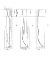
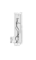
- FIG. 6 (a) is a diagram showing the state of stagnation of the refrigerant together with the discharge pressure and the suction pressure of the refrigerant, with the horizontal axis indicating time and the vertical axis indicating pressure and temperature. Further, the solid line indicates the degree of superheat of the compressor suction portion indicating a stagnation state, the dotted line indicates the refrigerant discharge pressure, and the alternate long and short dash line indicates the refrigerant suction pressure. Note that the degree of superheat of the compressor suction portion increases when the refrigerant stagnates and decreases when the stagnation of the refrigerant is eliminated.
- FIG. 6B is a diagram showing the refrigerant suction temperature Ts and the discharge temperature Td, with the horizontal axis representing time and the vertical axis representing temperature.
- the solid line indicates the discharge temperature Td, and the dotted line indicates the suction temperature Ts.
- FIG.6 (c) is the figure which showed the exit water temperature of a 1st water refrigerant
- the stagnation of the refrigerant means that the refrigerant amount decreases in the heating refrigerant cycle, and therefore the stagnation refrigerant determination process corresponds to a means for detecting a decrease in the refrigerant amount of the heating refrigerant cycle.
- the refrigerant is not included in the sleep refrigerant determination process under the condition that the compressor speed, the blower fan speed, the operation mode (corresponding to the outside air temperature and the environmental temperature) and the second water pump speed are not changed.
- the discharge temperature Td and the coolant outlet water temperature Tsc_out in the second water refrigerant heat exchanger 12 are used, the present invention is not limited to this.
- the determination may be made from the discharge pressure and the discharge temperature of the refrigerant under the above conditions. In this case, if the discharge pressure decreases at a constant discharge temperature, it is determined that the refrigerant has stagnated.
- the compressor intake section superheat degree indicating that the refrigerant cycle is in the state of a low refrigerant may be directly measured. In this case, if the heating degree is increased, it is determined that the refrigerant has stagnated.
- the air conditioner ECU 109 stops the first water pump 42 in the engine cooling unit 40, and in ST402, it is determined whether the difference between the blowing temperature and the target blowing temperature is equal to or greater than a predetermined threshold. If it is equal to or greater than the threshold (YES), the process returns to ST402 while the first water pump 42 is stopped. If the difference is less than the threshold (NO), the process proceeds to ST403.
- the air conditioner ECU 109 restarts the first water pump 42 and ends the sleeping refrigerant recovery operation.
- the first water pump in the engine cooling unit 40 is stopped, so that the low pressure of the first water refrigerant heat exchanger 11 is lowered, and the liquid refrigerant stored in the outdoor condenser 39 is compressed into the compressor. It can be recovered in 38 and returned to the heating refrigerant cycle.
- the first water pump 42 is stopped in the sleep refrigerant recovery operation.
- the present invention is not limited to this, and the number of rotations of the first water pump 42 is reduced to a predetermined value or less. Also good.
- the predetermined value may be a value smaller than the rotation speed of the first water pump 42 when the coolant temperature of the engine is stabilized.
- the air conditioner ECU 109 calculates a target blowing temperature.
- the air conditioner ECU 109 instructs the rotation speed of the compressor 38 based on the target blowing temperature, and in ST503, instructs the rotation speed of the second water pump 16 based on the target blowing temperature.
- FIG. 9 is a diagram showing how the refrigerant stagnates together with the refrigerant discharge pressure and the suction pressure.
- the horizontal axis indicates time
- the vertical axis indicates pressure and temperature.
- the solid line indicates the degree of superheat of the compressor suction portion indicating a stagnation state
- the dotted line indicates the refrigerant discharge pressure.
- the vehicle air conditioner 1 of the present embodiment includes the heating refrigerant cycle and the cooling refrigerant cycle that share the compressor 38 and a part of the path, and the air conditioner ECU 109 supplies the refrigerant to the cooling refrigerant cycle.
- the air conditioner ECU 109 supplies the refrigerant to the cooling refrigerant cycle.
- the first water refrigerant heat exchanger 11 circulates the coolant cyclically with the engine cooling unit 40 .
- the first water refrigerant heat exchanger 11 is, for example, a traveling motor used in an electric vehicle, an inverter for driving the traveling motor, a storage battery for supplying electric energy to the traveling motor, and charging a storage battery from the outside of the vehicle.
- a cooling liquid may be circulated between the heat generating member such as a charger for performing the conversion and a DC-DC converter for performing a voltage conversion of the storage battery.
- the vehicle air conditioner 1 includes the accumulator 17 .
- the present invention is not limited to this, and the accumulator 17 may not be provided.
- coolant heat exchanger 11 and the engine cooling part 40 are connected by piping h1 and h2 of a cooling liquid
- coolant heat exchanger 12 and the heater core 44 are a cooling liquid.
- the engine cooling unit 40 and the second water refrigerant heat exchanger 12 are connected by a coolant pipe h1
- the second water refrigerant heat exchanger 12 and the heater core 44 are connected to each other.
- the pipe h3 is connected, the heater core 44 and the first water refrigerant heat exchanger 11 are connected by a cooling pipe h4, and the first water refrigerant heat exchanger 11 and the engine cooling section 40 are connected by a cooling pipe h2. You may connect. Accordingly, the coolant circulates in the order of the engine cooling unit 40, the second water refrigerant heat exchanger 12, the heater core 44, the first water refrigerant heat exchanger 11, and the engine cooling unit 40.
- the refrigerant circuit in which the refrigerant discharged from the compressor 38 is sent to the outdoor capacitor 39 via the sub capacitor 12 during the cooling operation or the dehumidifying operation is shown, but the circuit configuration is not limited to this.
- FIG. 11 shows a modification of the refrigerant circuit of the vehicle air conditioner according to the embodiment.
- the refrigerant circuit of FIG. 11 branches the refrigerant piping at the discharge port of the compressor 38 and sends the refrigerant from the compressor 38 to the second water refrigerant heat exchanger 12, and the compressor 38 to the second water refrigerant heat exchanger 12. And a path for sending the refrigerant to the outdoor condenser 39 without being interposed.
- the refrigerant circuit of FIG. 11 has an on-off valve 13 and an on-off valve 15 for switching whether the refrigerant discharged from the compressor 38 is sent to the second water refrigerant heat exchanger 12 or to the outdoor condenser 39. .
- the refrigerant circuit of Embodiment 1 can be changed to the refrigerant circuit of FIG.
- the flow rate of the coolant flowing through the pipes h1 and h2 is adjusted by controlling the rotation speed of the first water pump 42 inside the engine cooling unit 40, but the present invention is not limited to this.
- the flow rate may be adjusted by using an on-off valve or a throttle valve instead of the water pump as the flow rate adjusting means.
- FIG. 12 is a configuration diagram showing a vehicle air conditioner according to Embodiment 2 of the present invention.
- the vehicle air conditioner 1 is a device that is mounted on a vehicle having an engine (internal combustion engine) and performs heating, dehumidification, and cooling of the passenger compartment.
- the vehicle air conditioner 1 includes a first water refrigerant heat exchanger 11, a second water refrigerant heat exchanger 12, an on-off valve 13, an expansion valve 14 with a solenoid valve, a water pump 16, an accumulator 17, an expansion valve 37, a compressor (compression). Machine) 38, an outdoor condenser 39, an engine cooling section 40, a heater core 44, an evaporator 48, and a cooling liquid pipe and a refrigerant pipe connecting them.
- the heater core 44 and the evaporator 48 are disposed in an intake passage of an HVAC (Heating, Ventilation, and Air Conditioning) 70.
- the HVAC 70 is provided with a blower fan (not shown) through which intake air flows.
- the first water refrigerant heat exchanger 11 has a passage through which a low-temperature and low-pressure refrigerant flows and a passage through which a coolant flows, and performs heat exchange between the refrigerant and the coolant.
- the first water refrigerant heat exchanger 11 is supplied with a low-temperature and low-pressure refrigerant in a predetermined operation mode, and the coolant is circulated between the engine cooling unit 40 via the pipes h1 and h2. To move heat from the coolant to the low temperature and low pressure refrigerant.
- the second water refrigerant heat exchanger 12 has a passage through which a high-temperature and high-pressure refrigerant flows and a passage through which a cooling liquid flows, and performs heat exchange between the refrigerant and the cooling liquid.
- a coolant is circulated between the heater core 44 and the heat from the high-temperature and high-pressure refrigerant to the coolant in a predetermined operation mode.
- a water pump 16 is provided on one of the two pipes h3 and h4 connected to the coolant inlet and the outlet of the second water refrigerant heat exchanger 12, respectively. These two pipes h3 and h4 are connected to the heater core 44.
- the water pump 16 is a pump capable of circulating the coolant between the second water refrigerant heat exchanger 12 and the heater core 44 by, for example, electrical driving.
- the refrigerant pipe j1 connected to the refrigerant inlet of the second water refrigerant heat exchanger 12 is connected to the discharge port of the compressor 38.
- the refrigerant pipe j2 connected to the refrigerant outlet of the second water refrigerant heat exchanger 12 is branched into two.
- One of the branched refrigerant pipes is connected to the refrigerant inlet of the outdoor capacitor 39 via the on-off valve 13.
- the other of the branched refrigerant pipes j3 is connected to the refrigerant inlet of the first water refrigerant heat exchanger 11 via an expansion valve 14 with a solenoid valve.
- the refrigerant pipe j4 connected to the refrigerant outlet of the first water refrigerant heat exchanger 11 is connected to the refrigerant inlet of the compressor 38 via the accumulator 17.
- the refrigerant pipe of the evaporator 48 is also joined to the refrigerant suction port of the compressor 38.
- the on-off valve 13 is a valve that switches between opening and closing of the refrigerant pipe, for example, by electrical control.
- the expansion valve 14 with a solenoid valve is a valve that functions as an expansion valve when the refrigerant pipe is opened and closed by, for example, electrical control and is opened.
- the accumulator 17 separates the vaporized refrigerant that has passed through the first water refrigerant heat exchanger 11 and the non-vaporized refrigerant, and sends only the vaporized refrigerant to the compressor 38.
- the compressor 38 is driven by electricity to compress the sucked refrigerant into a high temperature and high pressure and discharge it.
- the compressed refrigerant is sent to the second water refrigerant heat exchanger 12.
- the engine cooling unit 40 includes a water jacket for flowing a coolant around the engine and a pump for flowing the coolant to the water jacket, and releases heat from the engine to the coolant flowing in the water jacket.
- the pump is rotated by the power of the engine, for example.
- the heater core 44 is a device that exchanges heat between the coolant and air, and is disposed in the intake passage of the HVAC 70 that supplies air into the passenger compartment.
- the heater core 44 is supplied with a heated coolant and releases heat to the intake air that is sent into the passenger compartment during the heating operation.
- the evaporator 48 is a device that exchanges heat between the low-temperature and low-pressure refrigerant and the air, and is disposed in the intake passage of the HVAC 70.
- the evaporator 48 is supplied with a low-temperature and low-pressure refrigerant during the cooling operation or the dehumidifying operation, and cools the intake air supplied into the passenger compartment.
- the expansion valve 37 expands the high-pressure refrigerant to a low temperature and low pressure and discharges it to the evaporator 48.
- the expansion valve 37 is disposed in the vicinity of the evaporator 48.
- the outdoor condenser 39 has a passage through which the refrigerant flows and a passage through which the air flows.
- the outdoor condenser 39 is disposed near the top of the vehicle in the engine room and exchanges heat between the refrigerant and the outside air.
- a high-temperature and high-pressure refrigerant is passed through the outdoor condenser 39 in the cooling mode and the dehumidifying mode, and heat is discharged from the refrigerant to the outside air. Outside air is blown onto the outdoor condenser 39 by, for example, a fan.
- FIG. 13 is a diagram for explaining the operation in the heating mode in the vehicle air conditioner 1.
- the on-off valve 13 When the operation in the heating mode is requested, as shown in FIG. 13, the on-off valve 13 is closed, the expansion valve 14 with a solenoid valve is opened, and the water pump 16 is turned on.
- the compressor 38 when the compressor 38 is operated, the refrigerant passes through the second water refrigerant heat exchanger 12, the expansion valve 14 with a solenoid valve, the first water refrigerant heat exchanger 11, the accumulator 17, and the compressor 38 in this order. It flows cyclically. This path is called a heating refrigerant cycle (corresponding to a first refrigerant cycle).
- the high-temperature and high-pressure refrigerant compressed by the compressor 38 releases heat to the coolant in the second water refrigerant heat exchanger 12 and condenses. Further, the low-temperature and low-pressure refrigerant expanded by the expansion valve 14 with a solenoid valve is vaporized by absorbing heat from the coolant in the first water refrigerant heat exchanger 11.
- Coolant flows in two paths and flows independently.
- the coolant in the first path flows cyclically between the engine cooling unit 40 and the first water refrigerant heat exchanger 11.
- the coolant in the first path cools the engine in the engine cooling unit 40 and releases heat to the low-temperature and low-pressure refrigerant in the first water-refrigerant heat exchanger 11.
- the coolant in the second path flows cyclically between the second water refrigerant heat exchanger 12 and the heater core 44 by the water pump 16.
- the coolant in the second path absorbs heat from the high-temperature and high-pressure refrigerant in the second water-refrigerant heat exchanger 12 and releases heat to the intake air that is sent into the passenger compartment in the heater core 44.
- the vehicle air conditioner 1 has a high temperature because the refrigerant saturation pressure of the outdoor condenser 39 installed in a low temperature environment decreases at a low outdoor temperature (for example, ⁇ 20 ° C.).
- the pressure of the outdoor condenser 39 is lower than that of the first water-refrigerant heat exchanger 11, and the refrigerant pipe (cooling refrigerant cycle (second refrigerant cycle) of the evaporator 48 connected to the heating refrigerant cycle at the refrigerant inlet of the compressor 38 is joined.
- the refrigerant flows into a part of The refrigerant that has flowed into the refrigerant pipe of the evaporator 48 stagnates in the outdoor condenser 39.
- a check valve is not provided in the vehicle air conditioner 1 and an air conditioner ECU (Electronic Control Unit) controls each part in the apparatus to collect the sleeping refrigerant.
- ECU Electronic Control Unit
- FIG. 14 is a block diagram showing a functional configuration around the air conditioner ECU in the vehicle air conditioner 1 according to Embodiment 2 of the present invention.
- the discharge temperature detection unit 101 detects the temperature of the refrigerant discharged from the compressor 38 and notifies the air conditioner ECU 109 of the detected temperature of the refrigerant.
- the discharge pressure detection unit 102 detects the pressure of the refrigerant discharged from the compressor 38 and notifies the air conditioner ECU 109 of the detected refrigerant pressure.
- the operation mode storage unit 103 stores the current operation mode of the vehicle air conditioner 1, that is, the heating mode, the cooling mode, the dehumidifying mode, and the like, and notifies the air conditioner ECU 109 of the current operation mode.
- the AC switch unit 104 is a switch for the user to control the air conditioning in the passenger compartment, receives instructions from the user such as on / off of the air conditioner, temperature, and air volume, and outputs the instructions from the user to the air conditioner ECU 109.
- the compressor control unit 106 controls the rotation speed of the compressor 38 based on the control of the air conditioner ECU 109 and notifies the air conditioner ECU 109 of the rotation speed of the compressor 38 and the like.
- the blower fan control unit 107 controls the rotational speed of the blower fan in the HVAC 70 based on the control of the air conditioner ECU 109, and notifies the air conditioner ECU 109 of the rotational speed of the blower fan and the like.
- the water pump control unit 108 controls the rotation speed of the water pump 16 based on the control of the air conditioner ECU 109, and notifies the air conditioner ECU 109 of the rotation speed of the water pump 16 and the like.
- the air conditioner ECU 109 determines whether or not stagnation has occurred in the cooling refrigerant cycle during the heating mode based on information from the various detection units, switches, and various control units. The stagnation refrigerant recovery operation for recovery to the heating refrigerant cycle is performed, and the normal operation is performed when the stagnation does not occur. The detailed operation of the air conditioner ECU 109 will be described later.
- step (hereinafter abbreviated as “ST”) 201 the air conditioner EUC 109 is activated upon receiving an ignition ON operation.
- step (ST 202) the air conditioner ECU 109 opens and closes various doors provided in the various detection units and the HVAC 70. Initialize the actuator to perform.
- the air conditioner ECU 109 acquires detection information from various detection units, and in ST205, a sleeping refrigerant determination process is performed. Details of the sleeping refrigerant determination process will be described later.
- the air conditioner ECU 109 determines whether or not the refrigerant has stagnation as a result of the stagnation refrigerant determination process in ST205. If the stagnation has occurred (YES), the process proceeds to ST207 and the stagnation has occurred. If not (NO), the process proceeds to ST208.
- the air conditioner ECU 109 performs the sleep refrigerant recovery operation and returns to ST203. Details of the sleeping refrigerant recovery operation will be described later.
- the air conditioner ECU 109 performs normal operation and returns to ST203. Details of the normal operation will be described later.
- the air conditioner ECU 109 determines whether or not the rotation speed of the compressor 38 is changed. If there is no change (YES), the process proceeds to ST302, and if there is a change (NO), ST308. Migrate to
- the air conditioner ECU 109 determines whether or not there is a change in the rotation speed (air volume) of the blower fan in the HVAC 70. If there is no change (YES), the process proceeds to ST303, and if there is a change (NO). Moves to ST308.
- the air conditioner ECU 109 determines whether or not the operation mode is changed. If there is no change (YES), the process proceeds to ST304, and if there is a change (NO), the process proceeds to ST308.
- the air conditioner ECU 109 determines whether or not the rotation speed of the water pump 16 has changed, and if there is no change (YES), the process proceeds to ST305, and if there is a change (NO), the process proceeds to ST308. To do. Note that the procedures of ST301 to ST304 may be performed in any order, or may be performed simultaneously.
- the air conditioner ECU 109 determines whether or not the stagnation determination timer is set. If it is set (YES), the process proceeds to ST310, and if it is not set (NO), the process proceeds to ST306. .
- the air conditioner ECU 109 acquires the refrigerant discharge temperature Td and the coolant outlet water temperature Tsc_out in the second water refrigerant heat exchanger 12, and stores them as reference values.
- the stagnation determination timer is set.
- the set value Twait seconds is set, and the sleeping refrigerant determination process is terminated.
- the air conditioner ECU 109 deletes the stagnation determination timer set in ST307, and in ST309, determines that the refrigerant has not stagnation and ends the stagnation refrigerant determination process.
- the air conditioner ECU 109 determines whether the stagnation determination timer has passed the set value Twait seconds. If Twait seconds have elapsed (YES), the process proceeds to ST312, and if Twait seconds have not elapsed (NO), In ST311, it is determined that the refrigerant has not stagnation, and the stagnation refrigerant determination process is terminated.
- the air conditioner ECU 109 obtains the refrigerant discharge temperature Td and the coolant outlet water temperature Tsc_out in the second water refrigerant heat exchanger 12, and in ST313, the reference value stored in ST306 and the refrigerant obtained in ST312. From the discharge temperature Td and the coolant outlet water temperature Tsc_out, the condition that the refrigerant discharge temperature Td change ⁇ Td is 0 or more and the outlet water temperature change ⁇ Tsc_out of the second water refrigerant heat exchanger 12 is smaller than zero. Judge whether to meet. When this condition is satisfied (YES), the process proceeds to ST314, and when this condition is not satisfied (NO), the process proceeds to ST315.
- the air conditioner ECU 109 determines that the stagnation of the refrigerant has occurred, and in ST315, determines that the stagnation of the refrigerant has not occurred.
- the discharge temperature Td is constant under the condition that the compressor speed, the blower fan speed, the operation mode (corresponding to the outside air temperature and the environmental temperature) and the water pump speed are not changed. It is determined that the refrigerant has stagnated when the outlet water temperature Tsc_out of the second water-refrigerant heat exchanger 12 decreases despite the increase. Since the stagnation of the refrigerant means a decrease in the refrigerant amount in the heating refrigerant cycle, the stagnation refrigerant determination process corresponds to a means for detecting a decrease in the refrigerant amount in the heating refrigerant cycle.
- the refrigerant discharge temperature is included in the sleep refrigerant determination process under the condition that the compressor rotation speed, blower fan rotation speed, operation mode (corresponding to the outside air temperature and environmental temperature), and water pump rotation speed are not changed.
- Td and the coolant outlet water temperature Tsc_out in the second water refrigerant heat exchanger 12 are used, the present invention is not limited to this.
- the determination may be made from the discharge pressure and the discharge temperature of the refrigerant under the above conditions. In this case, if the discharge pressure decreases at a constant discharge temperature, it is determined that the refrigerant has stagnated. Further, the compressor intake section superheat degree indicating that the refrigerant cycle is in the state of a low refrigerant may be directly measured. In this case, when the superheat degree is increased, it is determined that the refrigerant has stagnated.
- the air conditioner ECU 109 sets a timer to a set value Ttimer (for example, 30 seconds), and in ST602, the compressor 38 is stopped.
- Ttimer for example, 30 seconds
- the air conditioner ECU 109 determines whether the timer has reached the set value Ttimer seconds. If Ttimer seconds have elapsed (YES), the process proceeds to ST604, and if Twait seconds have not elapsed (NO), the process returns to ST402. .
- the air conditioner ECU 109 restarts the compressor 38 and ends the stagnation refrigerant recovery operation.
- FIG. 6 shows an operation in which the compressor 38 is temporarily stopped and restarted once, intermittent operation in which this operation is repeated may be performed.
- the air conditioner ECU 109 calculates a target blowing temperature.
- the air conditioner ECU 109 instructs the rotation speed of the compressor 38 based on the target blowing temperature, and in ST503, instructs the rotation speed of the water pump 16 based on the target blowing temperature.
- FIG. 16 is a diagram showing how the refrigerant stagnates together with the refrigerant discharge pressure and the suction pressure.
- the horizontal axis indicates time
- the vertical axis indicates pressure and temperature.
- the solid line indicates the degree of superheat of the compressor suction portion indicating a stagnation state
- the dotted line indicates the refrigerant discharge pressure
- the alternate long and short dash line indicates the refrigerant suction pressure. Note that the degree of superheat of the compressor suction portion increases when the refrigerant stagnates and decreases when the stagnation of the refrigerant is eliminated.
- FIG. 16 shows that when the degree of superheat of the compressor suction increases and stagnation occurs, the discharge pressure starts to decrease.
- the stagnation refrigerant recovery operation is performed and the compressor 38 is temporarily stopped, the discharge pressure rapidly decreases, and when the compressor 38 is restarted, the discharge pressure returns and the suction pressure rapidly increases.
- the degree of superheat of the compressor suction portion also suddenly decreases, and the stagnation of the refrigerant is temporarily eliminated.
- the sleeping refrigerant recovery operation intermittentt operation of the compressor
- the vehicle air conditioner 1 of the present embodiment includes the heating refrigerant cycle and the cooling refrigerant cycle that share the compressor 38 and a part of the path, and the air conditioner ECU 109 supplies the refrigerant to the cooling refrigerant cycle. Is detected, the compressor 38 is temporarily stopped and then restarted.
- the refrigerant suction pressure of the compressor 38 temporarily decreases, and the liquid refrigerant stored in the cooling refrigerant cycle can be collected in the compressor 38 and returned to the heating refrigerant cycle. As a result, a decrease in heating performance can be suppressed.
- the present invention is not limited to this, and the accumulator 17 may not be provided.
- coolant flow path shown in FIG. 10 may be applied, or the refrigerant circuit shown in FIG. 11 may be applied.
- the compressor 38 is described as a compressor that can be driven by electricity and whose rotation speed can be controlled, such as an electric compressor, but may be a compressor that is driven by engine power.
- a compressor driven by the engine either a fixed capacity compressor having a fixed discharge capacity or a variable capacity compressor having a variable discharge capacity can be applied.
- the compressor driven by the engine can start the compression of the refrigerant by turning on the clutch, and can stop the compression of the refrigerant by turning off the clutch.
- “stop of the compressor 38” in ST601 of FIG. 15 can be realized by turning off the clutch.
- the “restart of the compressor 38” in ST604 in FIG. 15 can be realized by turning on the clutch.
- Aspect 1 is a path for circulating the refrigerant, the first refrigerant cycle forming the first heat pump cycle, and the path for circulating the refrigerant, forming a second heat pump cycle different from the first heat pump cycle, A second refrigerant cycle that shares a part of the path with the first refrigerant cycle, and a refrigerant that is included in the first refrigerant cycle and exchanges heat between the low-temperature and low-pressure refrigerant and the coolant of the heating member of the vehicle.
- the first water refrigerant heat exchanger to be vaporized the flow rate adjusting means for adjusting the flow rate of the coolant flowing through the heat generating member and the first water refrigerant heat exchanger, and the inflow of the refrigerant into the second refrigerant cycle.
- the flow rate adjusting unit is controlled to Air conditioning system comprising a control means for reducing the flow rate of the liquid.
- Aspect 2 is the vehicle air conditioner according to aspect 1, further comprising a compressor that is shared by the first refrigerant cycle and the second refrigerant cycle and compresses and discharges the refrigerant.
- Aspect 3 is the vehicle air conditioner according to aspect 1 or aspect 2, wherein the coolant is circulated between the heat generating member and the first water-refrigerant heat exchanger.
- Aspect 4 is a second water that condenses the refrigerant by exchanging heat between the heater core that gives heat to the air that is sent to the passenger compartment by flowing the cooling liquid, and the high-temperature and high-pressure refrigerant and the cooling liquid for heat transport.
- a refrigerant heat exchanger wherein the coolant is circulated between the heat generating member, the second water refrigerant heat exchanger, the heater core, and the first water refrigerant heat exchanger.
- Aspect 5 is any one of aspects 1 to 4, wherein the control means controls the flow rate adjusting means to reduce the flow rate of the coolant when the decrease in the refrigerant amount in the first refrigerant cycle is detected.
- the vehicle air conditioner according to aspect 2 including a two-water refrigerant heat exchanger.
- the second refrigerant cycle includes the compressor, a second water refrigerant heat exchanger that condenses the refrigerant by performing heat exchange between the high-temperature and high-pressure refrigerant and the coolant for heat transport, and the refrigerant.
- the second refrigerant cycle includes the compressor, an outdoor condenser that dissipates heat from the refrigerant to the outside air to condense the refrigerant, and an evaporator that absorbs heat from the intake air sent to the vehicle interior and vaporizes the refrigerant.
- the vehicle air conditioner according to aspect 2 or aspect 6.
- Aspect 9 is the vehicle air conditioner according to aspect 2, wherein the first refrigerant cycle and the second refrigerant cycle are joined together at the refrigerant inlet of the compressor.
- Aspect 10 is an aspect 9 in which the first refrigerant cycle and the second refrigerant cycle are joined and connected without using a valve that prevents the refrigerant from flowing into the second refrigerant cycle from the first refrigerant cycle.
- Aspect 11 is a path for circulating the refrigerant, the first refrigerant cycle forming the first heat pump cycle, and the path for circulating the refrigerant, forming a second heat pump cycle different from the first heat pump cycle, A second refrigerant cycle sharing a part of the path with the first refrigerant cycle, a detecting means for detecting a decrease in the amount of refrigerant in the first refrigerant cycle due to the inflow of refrigerant into the second refrigerant cycle, and the first Control means for performing control to stop and restart the compressor that compresses and discharges the refrigerant that is shared by the first refrigerant cycle and the second refrigerant cycle when a decrease in the refrigerant amount in the refrigerant cycle is detected;
- a vehicle air conditioner comprising:
- Aspect 12 is the vehicle air conditioner according to aspect 11, further comprising a compressor that is shared by the first refrigerant cycle and the second refrigerant cycle and compresses and discharges the refrigerant.
- Aspect 13 includes a first water refrigerant heat exchanger that exchanges heat between the compressor, the low-temperature and low-pressure refrigerant and the engine coolant, and vaporizes the refrigerant in the first refrigerant cycle, and a high-temperature and high-pressure refrigerant.
- the second refrigerant cycle includes the compressor, a second water refrigerant heat exchanger that condenses the refrigerant by exchanging heat between the high-temperature and high-pressure refrigerant and the coolant for heat transport, and the refrigerant.
- the outdoor condenser that dissipates heat to the outside air to condense the refrigerant, and the evaporator that absorbs heat from the intake air sent into the vehicle interior and vaporizes the refrigerant, according to any one of aspects 11 to 13.
- Vehicle air conditioner is any one of aspects 11 to 13.
- the compressor in the second refrigerant cycle, the compressor, an outdoor capacitor that dissipates heat from the refrigerant to the outside air to condense the refrigerant, and an evaporator that absorbs heat from the intake air sent to the vehicle interior and vaporizes the refrigerant.
- the vehicle air conditioner according to any one of aspects 11 to 13.
- Aspect 16 is the vehicle air conditioner according to any one of aspects 11 to 15, wherein the first refrigerant cycle and the second refrigerant cycle are joined and connected at the refrigerant inlet of the compressor.
- Aspect 17 is a mode 16 in which the first refrigerant cycle and the second refrigerant cycle are joined and connected without using a valve that prevents the refrigerant from flowing into the second refrigerant cycle from the first refrigerant cycle.
- the present invention can be used for a vehicle air conditioner mounted on a vehicle.
Landscapes
- Physics & Mathematics (AREA)
- Thermal Sciences (AREA)
- Engineering & Computer Science (AREA)
- Mechanical Engineering (AREA)
- Air-Conditioning For Vehicles (AREA)
Abstract
Description
図1は、本発明の実施の形態1に係る車両用空調装置を示す構成図である。
図2は、車両用空調装置1における暖房モードの動作を説明する図である。
図3は、本発明の実施の形態1に係る車両用空調装置1におけるエアコンECU周辺の機能構成を示すブロック図である。
次に、上述したエアコンECU109の詳細な動作について、図4を用いて説明する。
次に、図4に示した寝込み冷媒判定処理について、図5を用いて説明する。
次に、図4に示した寝込み冷媒回収運転について、図7を用いて説明する。
次に、図4に示した通常運転について、図8を用いて説明する。
図9は、冷媒の寝込みの様子を冷媒の吐出圧力および吸入圧力と共に示した図である。図9において、横軸が時間を、縦軸が圧力および温度を示している。また、実線が寝込みの状態を示すコンプレッサ吸入部過熱度を、点線が冷媒の吐出圧力をそれぞれ示している。
このように、本実施の形態の車両用空調装置1では、コンプレッサ38および一部の経路を共用する暖房用冷媒サイクルと冷房用冷媒サイクルとを有し、エアコンECU109が冷房用冷媒サイクルへの冷媒の流入による暖房用冷媒サイクルにおける冷媒量の減少を検知した場合、第1水冷媒熱交換器11とエンジン冷却部40との間で冷却液を輸送する第1ウォータポンプ42を停止させる。
また、本実施の形態では、第1水冷媒熱交換器11とエンジン冷却部40とを冷却液の配管h1、h2で接続し、第2水冷媒熱交換器12とヒーターコア44とを冷却液の配管h3、h4で接続する場合について示したが、これに制限されない。例えば、図10に示すように、エンジン冷却部40と第2水冷媒熱交換器12とを冷却液の配管h1で接続し、第2水冷媒熱交換器12とヒーターコア44とを冷却液の配管h3で接続し、ヒーターコア44と第1水冷媒熱交換器11とを冷却液の配管h4で接続し、第1水冷媒熱交換器11とエンジン冷却部40とを冷却液の配管h2で接続してもよい。これにより、エンジン冷却部40、第2水冷媒熱交換器12、ヒーターコア44、第1水冷媒熱交換器11、エンジン冷却部40の順に冷却液が循環する。
図12は、本発明の実施の形態2に係る車両用空調装置を示す構成図である。
図13は、車両用空調装置1における暖房モードの動作を説明する図である。
図14は、本発明の実施の形態2に係る車両用空調装置1におけるエアコンECU周辺の機能構成を示すブロック図である。
次に、上述したエアコンECU109の詳細な動作について、図4を用いて説明する。
次に、図4に示した寝込み冷媒判定処理について、図5を用いて説明する。
次に、図4に示した寝込み冷媒回収運転について、図15を用いて説明する。
次に、図4に示した通常運転について、図8を用いて説明する。
図16は、冷媒の寝込みの様子を冷媒の吐出圧力および吸入圧力と共に示した図である。図16において、横軸が時間を、縦軸が圧力および温度を示している。また、実線が寝込みの状態を示すコンプレッサ吸入部過熱度を、点線が冷媒の吐出圧力を、一点鎖線が冷媒の吸入圧力をそれぞれ示している。なお、コンプレッサ吸入部過熱度は、冷媒が寝込むと大きくなり、冷媒の寝込みが解消すると小さくなる。
このように、本実施の形態の車両用空調装置1では、コンプレッサ38および一部の経路を共用する暖房用冷媒サイクルと冷房用冷媒サイクルとを有し、エアコンECU109が冷房用冷媒サイクルへの冷媒の流入による暖房用冷媒サイクルにおける冷媒量の減少を検知した場合、コンプレッサ38を一時停止した後、再始動させる。
続いて、本発明にかかる一態様の概要を記載する。
11 第1水冷媒熱交換器
12 第2水冷媒熱交換器
13、15 開閉弁
14 電磁弁付き膨張弁
16 第2ウォータポンプ
37、43 膨張弁
38 コンプレッサ
39 室外コンデンサ
40 エンジン冷却部
42 第1ウォータポンプ
44 ヒーターコア
48 エバポレータ
70 HVAC
h1~h4 配管
j1~j4 冷媒配管
101 吐出温度検出部
102 吐出圧力検出部
103 運転モード記憶部
104 ACスイッチ部
105 吹き出し温度検出部
106 コンプレッサ制御部
107 ブロアファン制御部
108 ウォータポンプ制御部
109 エアコンECU
Claims (17)
- 冷媒を循環させる経路であって、第1ヒートポンプサイクルを形成する第1冷媒サイクルと、
冷媒を循環させる経路であって、前記第1ヒートポンプサイクルと異なる第2ヒートポンプサイクルを形成し、前記第1冷媒サイクルと一部の経路を共用する第2冷媒サイクルと、
前記第1冷媒サイクルに含まれ、低温低圧冷媒と車両の発熱部材の冷却液との間で熱交換を行って冷媒を気化させる第1水冷媒熱交換器と、
前記発熱部材および前記第1水冷媒熱交換器を流れる前記冷却液の流量を調整する流量調整手段と、
前記第2冷媒サイクルへの冷媒の流入による前記第1冷媒サイクルにおける冷媒量の減少を検知する検知手段と、
前記第1冷媒サイクルにおける冷媒量の減少が検知された場合、前記流量調整手段を制御し、前記冷却液の流量を低下させる制御手段と、
を具備する車両用空調装置。 - 前記第1冷媒サイクルと前記第2冷媒サイクルとで共用し、冷媒を圧縮して吐出するコンプレッサを、更に具備する、
請求項1に記載の車両用空調装置。 - 前記発熱部材と前記第1水冷媒熱交換器との間で前記冷却液を循環させる、
請求項1または請求項2に記載の車両用空調装置。 - 冷却液が流されて車室内へ送られる空気に熱を与えるヒーターコアと、
高温高圧冷媒と熱輸送用の冷却液との間で熱交換を行って冷媒を凝縮させる第2水冷媒熱交換器と、をさらに具備し、
前記発熱部材、前記第2水冷媒熱交換器、前記ヒーターコア、および、前記第1水冷媒熱交換器、の間で前記冷却液を循環させる、
請求項1または請求項2に記載の車両用空調装置。 - 前記制御手段は、前記第1冷媒サイクルにおける冷媒量の減少が検知された場合、前記流量調整手段を制御し、前記冷却液の流量をゼロにする、
請求項1から請求項4のいずれか一項に記載の車両用空調装置。 - 前記第1冷媒サイクルには、
前記コンプレッサと、
前記第1水冷媒熱交換器と、
高温高圧冷媒と熱輸送用の冷却液との間で熱交換を行って冷媒を凝縮させる第2水冷媒熱交換器と、
が含まれる請求項2に記載の車両用空調装置。 - 前記第2冷媒サイクルには、
前記コンプレッサと、
高温高圧冷媒と熱輸送用の冷却液との間で熱交換を行って冷媒を凝縮させる第2水冷媒熱交換器と、
冷媒から外気に熱を放熱させて冷媒を凝縮させる室外コンデンサと、
車室内へ送られる吸気から熱を吸収して冷媒を気化させるエバポレータと、
が含まれる請求項2または請求項6に記載の車両用空調装置。 - 前記第2冷媒サイクルには、
前記コンプレッサと、
冷媒から外気に熱を放熱させて冷媒を凝縮させる室外コンデンサと、
車室内へ送られる吸気から熱を吸収して冷媒を気化させるエバポレータと、
が含まれる請求項2または請求項6に記載の車両用空調装置。 - 前記第1冷媒サイクルと前記第2冷媒サイクルとが、前記コンプレッサの冷媒吸入口で合流接続されている、
請求項2に記載の車両用空調装置。 - 前記第1冷媒サイクルから前記第2冷媒サイクルへの冷媒の流入を阻止する弁を介さずに、前記第1冷媒サイクルと前記第2冷媒サイクルとが合流接続されている、
請求項9に記載の車両用空調装置。 - 冷媒を循環させる経路であって、第1ヒートポンプサイクルを形成する第1冷媒サイクルと、
冷媒を循環させる経路であって、前記第1ヒートポンプサイクルと異なる第2ヒートポンプサイクルを形成し、前記第1冷媒サイクルと一部の経路を共用する第2冷媒サイクルと、
前記第2冷媒サイクルへの冷媒の流入による前記第1冷媒サイクルにおける冷媒量の減少を検知する検知手段と、
前記第1冷媒サイクルにおける冷媒量の減少が検知された場合、前記第1冷媒サイクルと前記第2冷媒サイクルとで共用し冷媒を圧縮して吐出するコンプレッサを停止してから再始動させる制御を行う制御手段と、
を具備する車両用空調装置。 - 前記第1冷媒サイクルと前記第2冷媒サイクルとで共用し、冷媒を圧縮して吐出する前記コンプレッサを、更に具備する、
請求項11に記載の車両用空調装置。 - 前記第1冷媒サイクルには、
前記コンプレッサと、
低温低圧冷媒とエンジンの冷却液との間で熱交換を行って冷媒を気化させる第1水冷媒熱交換器と、
高温高圧冷媒と熱輸送用の冷却液との間で熱交換を行って冷媒を凝縮させる第2水冷媒熱交換器と、
が含まれる請求項11または請求項12に記載の車両用空調装置。 - 前記第2冷媒サイクルには、
前記コンプレッサと、
高温高圧冷媒と熱輸送用の冷却液との間で熱交換を行って冷媒を凝縮させる第2水冷媒熱交換器と、
冷媒から外気に熱を放熱させて冷媒を凝縮させる室外コンデンサと、
車室内へ送られる吸気から熱を吸収して冷媒を気化させるエバポレータと、
が含まれる請求項11から請求項13のいずれか一項に記載の車両用空調装置。 - 前記第2冷媒サイクルには、
前記コンプレッサと、
冷媒から外気に熱を放熱させて冷媒を凝縮させる室外コンデンサと、
車室内へ送られる吸気から熱を吸収して冷媒を気化させるエバポレータと、
が含まれる請求項11から請求項13のいずれか一項に記載の車両用空調装置。 - 前記第1冷媒サイクルと前記第2冷媒サイクルとが、前記コンプレッサの冷媒吸入口で合流接続されている、
請求項11から請求項15のいずれか一項に記載の車両用空調装置。 - 前記第1冷媒サイクルから前記第2冷媒サイクルへの冷媒の流入を阻止する弁を介さずに、前記第1冷媒サイクルと前記第2冷媒サイクルとが合流接続されている、
請求項16に記載の車両用空調装置。
Priority Applications (4)
| Application Number | Priority Date | Filing Date | Title |
|---|---|---|---|
| EP14760661.0A EP2965932B1 (en) | 2013-03-06 | 2014-03-05 | Vehicle air conditioning device |
| US14/769,982 US20160001634A1 (en) | 2013-03-06 | 2014-03-05 | Vehicle air conditioning device |
| CN201480011815.8A CN105026195B (zh) | 2013-03-06 | 2014-03-05 | 车辆用空调装置 |
| JP2015504181A JP6274201B2 (ja) | 2013-03-06 | 2014-03-05 | 車両用空調装置 |
Applications Claiming Priority (4)
| Application Number | Priority Date | Filing Date | Title |
|---|---|---|---|
| JP2013-044136 | 2013-03-06 | ||
| JP2013044136 | 2013-03-06 | ||
| JP2013-044133 | 2013-03-06 | ||
| JP2013044133 | 2013-03-06 |
Publications (1)
| Publication Number | Publication Date |
|---|---|
| WO2014136450A1 true WO2014136450A1 (ja) | 2014-09-12 |
Family
ID=51490983
Family Applications (1)
| Application Number | Title | Priority Date | Filing Date |
|---|---|---|---|
| PCT/JP2014/001213 WO2014136450A1 (ja) | 2013-03-06 | 2014-03-05 | 車両用空調装置 |
Country Status (5)
| Country | Link |
|---|---|
| US (1) | US20160001634A1 (ja) |
| EP (1) | EP2965932B1 (ja) |
| JP (1) | JP6274201B2 (ja) |
| CN (1) | CN105026195B (ja) |
| WO (1) | WO2014136450A1 (ja) |
Cited By (5)
| Publication number | Priority date | Publication date | Assignee | Title |
|---|---|---|---|---|
| CN107000543A (zh) * | 2014-11-27 | 2017-08-01 | 康奈可关精株式会社 | 车辆用空调装置 |
| EP3319822A4 (en) * | 2015-06-15 | 2018-09-26 | BYD Company Limited | Air conditioning system for vehicle and vehicle having same |
| WO2019054401A1 (ja) * | 2017-09-15 | 2019-03-21 | 株式会社ヴァレオジャパン | 冷凍サイクル装置 |
| JP2019515238A (ja) * | 2016-05-02 | 2019-06-06 | ウォン, リー, ワWONG, Lee, Wa | エネルギ効率が良いセントラル空調及びヒートポンプシステム |
| JP2019100688A (ja) * | 2017-12-08 | 2019-06-24 | 株式会社デンソー | ヒートポンプシステム |
Families Citing this family (13)
| Publication number | Priority date | Publication date | Assignee | Title |
|---|---|---|---|---|
| CN106322505A (zh) * | 2015-06-15 | 2017-01-11 | 比亚迪股份有限公司 | 汽车空调系统及其控制方法、汽车 |
| CN106314064B (zh) * | 2015-06-15 | 2018-10-16 | 比亚迪股份有限公司 | 汽车空调系统及其控制方法、汽车 |
| JP6565744B2 (ja) * | 2016-03-10 | 2019-08-28 | 株式会社デンソー | 空調装置 |
| DE102016112095A1 (de) * | 2016-07-01 | 2018-01-04 | Hanon Systems | System zum Klimatisieren der Luft eines Fahrgastraums und zur Wärmeübertragung mit Antriebskomponenten eines Kraftfahrzeugs sowie Verfahren zum Betreiben des Systems |
| CN106335340A (zh) * | 2016-08-29 | 2017-01-18 | 博耐尔汽车电气系统有限公司 | 一种热泵汽车空调 |
| JP6798441B2 (ja) | 2017-07-31 | 2020-12-09 | 株式会社デンソー | 冷凍サイクル装置 |
| CN107388663B (zh) * | 2017-08-03 | 2019-03-26 | 珠海格力电器股份有限公司 | 热泵系统的控制方法及热泵系统 |
| JP6794964B2 (ja) * | 2017-08-31 | 2020-12-02 | 株式会社デンソー | 冷凍サイクル装置 |
| JP2019060580A (ja) * | 2017-09-28 | 2019-04-18 | 株式会社デンソー | 冷凍サイクル装置 |
| GB201718141D0 (en) * | 2017-11-02 | 2017-12-20 | Rolls Royce Plc | Thermal management system |
| FR3077030B1 (fr) * | 2018-01-22 | 2021-02-26 | Renault Sas | Dispositif de pilotage d'un ensemble de refroidissement pour vehicule automobile |
| WO2019203963A1 (en) * | 2018-04-16 | 2019-10-24 | Carrier Corporation | Dual compressor heat pump |
| CN108593996B (zh) * | 2018-05-11 | 2023-08-08 | 沈阳工业大学 | 一种基于液体导热的电介质热刺激电流测量装置及方法 |
Citations (5)
| Publication number | Priority date | Publication date | Assignee | Title |
|---|---|---|---|---|
| JPH08197937A (ja) | 1993-12-27 | 1996-08-06 | Nippondenso Co Ltd | 車両用空気調和装置 |
| JP2000211347A (ja) * | 1999-01-27 | 2000-08-02 | Japan Climate Systems Corp | 車両用空調装置 |
| US20050224221A1 (en) * | 2002-06-06 | 2005-10-13 | Behr Gmbh & Co. Kg | Air conditioner for a motor vehicle |
| WO2012160434A1 (en) * | 2011-05-26 | 2012-11-29 | Toyota Jidosha Kabushiki Kaisha | Cooling system and vehicle |
| WO2013000547A1 (fr) * | 2011-06-20 | 2013-01-03 | Valeo Systemes Thermiques | Circuit de fluide refrigerant avec deux moyens de stockage du fluide refrigerant |
Family Cites Families (10)
| Publication number | Priority date | Publication date | Assignee | Title |
|---|---|---|---|---|
| JP2000211349A (ja) * | 1999-01-27 | 2000-08-02 | Japan Climate Systems Corp | 車両用空調装置 |
| LU90841B1 (en) * | 2001-09-25 | 2003-03-26 | Delphi Tech Inc | Combined heating and cooling system |
| JP4085694B2 (ja) * | 2002-02-27 | 2008-05-14 | 株式会社デンソー | 空気調和装置 |
| US6862892B1 (en) * | 2003-08-19 | 2005-03-08 | Visteon Global Technologies, Inc. | Heat pump and air conditioning system for a vehicle |
| JP2005263200A (ja) * | 2004-02-18 | 2005-09-29 | Denso Corp | 車両用空調装置 |
| JP4797727B2 (ja) * | 2006-03-22 | 2011-10-19 | ダイキン工業株式会社 | 冷凍装置 |
| JP2007278624A (ja) * | 2006-04-07 | 2007-10-25 | Denso Corp | ヒートポンプサイクル |
| JP2011031679A (ja) * | 2009-07-30 | 2011-02-17 | Sanden Corp | 車両用空調装置 |
| FR2963408B1 (fr) * | 2010-08-02 | 2014-07-04 | Valeo Systemes Thermiques | Systeme de climatisation, notamment d'un vehicule automobile, comprenant une boucle de climatisation et une boucle secondaire cooperant avec la boucle de climatisation |
| KR20130041640A (ko) * | 2011-10-17 | 2013-04-25 | 엘지전자 주식회사 | 공기조화기 및 그 운전 방법 |
-
2014
- 2014-03-05 EP EP14760661.0A patent/EP2965932B1/en active Active
- 2014-03-05 CN CN201480011815.8A patent/CN105026195B/zh active Active
- 2014-03-05 JP JP2015504181A patent/JP6274201B2/ja not_active Expired - Fee Related
- 2014-03-05 WO PCT/JP2014/001213 patent/WO2014136450A1/ja active Application Filing
- 2014-03-05 US US14/769,982 patent/US20160001634A1/en not_active Abandoned
Patent Citations (5)
| Publication number | Priority date | Publication date | Assignee | Title |
|---|---|---|---|---|
| JPH08197937A (ja) | 1993-12-27 | 1996-08-06 | Nippondenso Co Ltd | 車両用空気調和装置 |
| JP2000211347A (ja) * | 1999-01-27 | 2000-08-02 | Japan Climate Systems Corp | 車両用空調装置 |
| US20050224221A1 (en) * | 2002-06-06 | 2005-10-13 | Behr Gmbh & Co. Kg | Air conditioner for a motor vehicle |
| WO2012160434A1 (en) * | 2011-05-26 | 2012-11-29 | Toyota Jidosha Kabushiki Kaisha | Cooling system and vehicle |
| WO2013000547A1 (fr) * | 2011-06-20 | 2013-01-03 | Valeo Systemes Thermiques | Circuit de fluide refrigerant avec deux moyens de stockage du fluide refrigerant |
Cited By (5)
| Publication number | Priority date | Publication date | Assignee | Title |
|---|---|---|---|---|
| CN107000543A (zh) * | 2014-11-27 | 2017-08-01 | 康奈可关精株式会社 | 车辆用空调装置 |
| EP3319822A4 (en) * | 2015-06-15 | 2018-09-26 | BYD Company Limited | Air conditioning system for vehicle and vehicle having same |
| JP2019515238A (ja) * | 2016-05-02 | 2019-06-06 | ウォン, リー, ワWONG, Lee, Wa | エネルギ効率が良いセントラル空調及びヒートポンプシステム |
| WO2019054401A1 (ja) * | 2017-09-15 | 2019-03-21 | 株式会社ヴァレオジャパン | 冷凍サイクル装置 |
| JP2019100688A (ja) * | 2017-12-08 | 2019-06-24 | 株式会社デンソー | ヒートポンプシステム |
Also Published As
| Publication number | Publication date |
|---|---|
| JPWO2014136450A1 (ja) | 2017-02-09 |
| JP6274201B2 (ja) | 2018-02-07 |
| EP2965932A1 (en) | 2016-01-13 |
| US20160001634A1 (en) | 2016-01-07 |
| EP2965932A4 (en) | 2017-03-29 |
| CN105026195B (zh) | 2017-04-26 |
| EP2965932B1 (en) | 2019-05-08 |
| CN105026195A (zh) | 2015-11-04 |
Similar Documents
| Publication | Publication Date | Title |
|---|---|---|
| JP6274201B2 (ja) | 車両用空調装置 | |
| JP6605928B2 (ja) | 車両用空調装置 | |
| JP6388213B2 (ja) | 車両用空調装置 | |
| JP5005122B2 (ja) | 車両用空調装置 | |
| WO2013136693A1 (ja) | 冷凍サイクル装置 | |
| JP5786615B2 (ja) | 自動車用温調システム | |
| US10583711B2 (en) | Vehicular temperature regulation device | |
| JP2020172178A (ja) | 車載温調装置 | |
| JP2020168950A (ja) | 車載温調装置 | |
| JP2015101180A (ja) | ヒートポンプシステム | |
| JP6432046B2 (ja) | 車両用空調装置 | |
| WO2014136423A1 (ja) | 車両用空調装置およびその構成ユニット | |
| EP3878670A1 (en) | In-vehicle temperature control system | |
| JP6358424B2 (ja) | 吸気温度制御システム | |
| JP5096956B2 (ja) | 車両用空気調和システム | |
| JPWO2015008463A1 (ja) | 車両用空調装置およびその構成ユニット | |
| JP6315222B2 (ja) | 車両用空調装置の構成ユニット | |
| JP5517891B2 (ja) | 空気調和装置 | |
| JP6167891B2 (ja) | ヒートポンプサイクル装置。 | |
| JP2020199870A (ja) | 車両用空調装置 | |
| WO2017163687A1 (ja) | 車両用空調装置および空調制御方法 | |
| JP2014149103A (ja) | 冷凍サイクル装置 | |
| JP5803526B2 (ja) | 自動車用冷凍システム、及び、自動車用温調システム | |
| JP2012076589A (ja) | 車両用空調装置 | |
| JP2002168534A (ja) | ヒートポンプ式空調装置 |
Legal Events
| Date | Code | Title | Description |
|---|---|---|---|
| WWE | Wipo information: entry into national phase |
Ref document number: 201480011815.8 Country of ref document: CN |
|
| 121 | Ep: the epo has been informed by wipo that ep was designated in this application |
Ref document number: 14760661 Country of ref document: EP Kind code of ref document: A1 |
|
| ENP | Entry into the national phase |
Ref document number: 2015504181 Country of ref document: JP Kind code of ref document: A |
|
| WWE | Wipo information: entry into national phase |
Ref document number: 2014760661 Country of ref document: EP |
|
| WWE | Wipo information: entry into national phase |
Ref document number: 14769982 Country of ref document: US |
|
| NENP | Non-entry into the national phase |
Ref country code: DE |