WO2014136290A1 - 履帯連結装置 - Google Patents
履帯連結装置 Download PDFInfo
- Publication number
- WO2014136290A1 WO2014136290A1 PCT/JP2013/072246 JP2013072246W WO2014136290A1 WO 2014136290 A1 WO2014136290 A1 WO 2014136290A1 JP 2013072246 W JP2013072246 W JP 2013072246W WO 2014136290 A1 WO2014136290 A1 WO 2014136290A1
- Authority
- WO
- WIPO (PCT)
- Prior art keywords
- crawler belt
- pin
- link
- master pin
- groove
- Prior art date
- Legal status (The legal status is an assumption and is not a legal conclusion. Google has not performed a legal analysis and makes no representation as to the accuracy of the status listed.)
- Ceased
Links
Images




Classifications
-
- B—PERFORMING OPERATIONS; TRANSPORTING
- B62—LAND VEHICLES FOR TRAVELLING OTHERWISE THAN ON RAILS
- B62D—MOTOR VEHICLES; TRAILERS
- B62D55/00—Endless track vehicles
- B62D55/08—Endless track units; Parts thereof
- B62D55/18—Tracks
- B62D55/20—Tracks of articulated type, e.g. chains
- B62D55/205—Connections between track links
- B62D55/21—Links connected by transverse pivot pins
- B62D55/213—Master track links
-
- B—PERFORMING OPERATIONS; TRANSPORTING
- B62—LAND VEHICLES FOR TRAVELLING OTHERWISE THAN ON RAILS
- B62D—MOTOR VEHICLES; TRAILERS
- B62D55/00—Endless track vehicles
- B62D55/08—Endless track units; Parts thereof
- B62D55/18—Tracks
- B62D55/20—Tracks of articulated type, e.g. chains
- B62D55/205—Connections between track links
- B62D55/21—Links connected by transverse pivot pins
-
- B—PERFORMING OPERATIONS; TRANSPORTING
- B62—LAND VEHICLES FOR TRAVELLING OTHERWISE THAN ON RAILS
- B62D—MOTOR VEHICLES; TRAILERS
- B62D55/00—Endless track vehicles
- B62D55/06—Endless track vehicles with tracks without ground wheels
-
- B—PERFORMING OPERATIONS; TRANSPORTING
- B62—LAND VEHICLES FOR TRAVELLING OTHERWISE THAN ON RAILS
- B62D—MOTOR VEHICLES; TRAILERS
- B62D55/00—Endless track vehicles
- B62D55/08—Endless track units; Parts thereof
- B62D55/18—Tracks
- B62D55/26—Ground engaging parts or elements
- B62D55/28—Ground engaging parts or elements detachable
-
- E—FIXED CONSTRUCTIONS
- E02—HYDRAULIC ENGINEERING; FOUNDATIONS; SOIL SHIFTING
- E02F—DREDGING; SOIL-SHIFTING
- E02F3/00—Dredgers; Soil-shifting machines
- E02F3/04—Dredgers; Soil-shifting machines mechanically-driven
- E02F3/28—Dredgers; Soil-shifting machines mechanically-driven with digging tools mounted on a dipper- or bucket-arm, i.e. there is either one arm or a pair of arms, e.g. dippers, buckets
- E02F3/30—Dredgers; Soil-shifting machines mechanically-driven with digging tools mounted on a dipper- or bucket-arm, i.e. there is either one arm or a pair of arms, e.g. dippers, buckets with a dipper-arm pivoted on a cantilever beam, i.e. boom
- E02F3/32—Dredgers; Soil-shifting machines mechanically-driven with digging tools mounted on a dipper- or bucket-arm, i.e. there is either one arm or a pair of arms, e.g. dippers, buckets with a dipper-arm pivoted on a cantilever beam, i.e. boom working downwardly and towards the machine, e.g. with backhoes
-
- E—FIXED CONSTRUCTIONS
- E02—HYDRAULIC ENGINEERING; FOUNDATIONS; SOIL SHIFTING
- E02F—DREDGING; SOIL-SHIFTING
- E02F9/00—Component parts of dredgers or soil-shifting machines, not restricted to one of the kinds covered by groups E02F3/00 - E02F7/00
- E02F9/02—Travelling-gear, e.g. associated with slewing gears
Definitions
- the present invention relates to a crawler belt coupling device, and more particularly to a crawler belt coupling device provided with a master pin.
- the track includes a belt-like track link chain in which a plurality of track links are connected.
- the belt-like crawler belt link chain is turned into an endless crawler belt by connecting the crawler belt links at both ends thereof, and is wound around the traveling device.
- the traveling device is composed of drive wheels, idle wheels, track frames, and the like.
- a special track pin or a special track link is used as a device for connecting both ends of the track link chain.
- the former is called a master pin, and the latter is called a master link.
- the crawler belt may be detached from the traveling device for reasons such as replacement of consumable parts. When this crawler belt is detached from the traveling device, it is necessary to connect / disconnect the crawler belt link chain.
- the master pin When the master pin is used as a connecting device, the master pin is attached to or detached from the crawler belt link to connect / disconnect the crawler belt link chain.
- a press machine is required to remove the master pin. Therefore, in order to detach the crawler belt from the traveling device at the work site of the work vehicle, a press machine is required. Therefore, in the work of removing and attaching the crawler belt at the work site, it takes time to prepare a press machine, and the workability is not good.
- Patent Document 1 Japanese Utility Model Laid-Open Publication No. 64-1078
- Patent Document 1 includes a master pin that can be attached to and detached from the crawler belt link, and a retaining pin for preventing the master pin from coming off from the crawler belt link.
- a device has been proposed.
- the master pin can be attached to and detached from the crawler belt link without using a press by inserting and removing the retaining pin.
- a hook is provided at one end of the master pin, and a retaining pin can be inserted at the other end.
- the crawler belt link is provided with a locking boss that engages with the collar of the master pin. The engagement of the master pin with respect to the crawler belt link can be suppressed by the engagement of the heel of the master pin and the locking boss of the crawler belt link.
- the locking boss is worn by the contact of the crest corner of the master pin with the locking boss of the crawler belt link as the crawler belt is used. This increases the gap between the crawler belt locking boss and the master pin heel, so that the master pin rotates around the crawler belt link. Furthermore, there is a possibility that the master pin may come off from the crawler belt link.
- the present invention has been made in view of the above-described problems, and an object of the present invention is to provide a crawler belt coupling device that can improve the workability of the crawler belt detachment and can prevent the master pin from falling off the crawler belt link. Is to provide.
- the crawler belt coupling apparatus of the present invention includes a first crawler belt link, a second crawler belt link, a master pin, a rotation stopper pin, and a snap ring.
- the first crawler belt link has a first through hole.
- the second crawler belt link is disposed to face the first crawler belt link, has a second through hole, and has a groove formed on an end surface opposite to the first crawler belt link.
- the master pin is inserted into the first and second through holes.
- the master pin is formed with an insertion hole penetrating in the radial direction of the master pin.
- the locking pin is press-fitted into the insertion hole, and both ends protrude from the master pin.
- the snap ring has a C shape, has an outer diameter larger than that of the first through hole, is located on the opposite side of the second crawler belt link with respect to the first through hole, and is attached to the master pin. Yes.
- the groove has a width smaller than the diameter of the master pin.
- the detent pin is disposed in the groove.
- the groove has a width smaller than the diameter of the master pin, the link boss part of the second crawler belt link provided around the groove can be formed thick. For this reason, wear of the link boss part can be suppressed. Thereby, it can prevent that a master pin rotates with respect to a 2nd crawler belt link.
- the detent pin has a cylindrical shape, and the groove has an arc-shaped bottom surface along the cylindrical shape. For this reason, the detent pin can be in surface contact with the bottom surface of the groove. Therefore, wear of the groove due to contact with the rotation stopper pin can be suppressed. Thereby, it is possible to avoid the master pin from falling off from the second crawler belt link.
- the diameter of the central portion of the detent pin is smaller than the diameter of both side portions sandwiching the central portion. For this reason, a gap can be formed between the center portion and the inner peripheral surface of the insertion hole while both sides are press-fitted into the insertion hole. As a result, the contact resistance between the rotation stopper pin and the insertion hole is reduced, so that the rotation stopper pin can be easily inserted into the insertion hole.
- the detent pin is arranged at the center in the length direction of the groove. For this reason, it is possible to make it difficult for the anti-rotation pin to come off from both sides in the length direction of the groove.
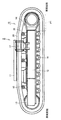
- the idler wheel 13 is rotatably provided at the front end of the track frame 12, and the drive wheel 14 is rotatably provided at the rear end of the track frame 12.
- the plurality of upper rollers 15 are provided on the upper surface side of the track frame 12, and the plurality of lower rollers 16 are provided on the lower surface side of the track frame 12.
- the crawler belt coupling device is provided at an end link of the endless belt-like crawler belt link chain 20, and connects both ends of the crawler belt link chain to form an endless crawler belt link chain 20. It is a device for.
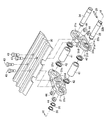
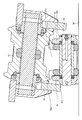
- the crawler belt coupling apparatus according to the present embodiment mainly includes a first crawler belt link 21, a second crawler belt link 31, a master pin 22, a detent pin 25, and a snap ring 26.
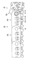
- the crawler belt link 20 a at one location of the crawler belt link chain 20 constitutes a part of the crawler belt coupling device, and has a first crawler belt link 21 and a second crawler belt link 31 that form a pair.
- the first crawler belt link 21 and the second crawler belt link 31 are spaced apart and arranged in parallel in a direction (crawler belt width direction) orthogonal to the connection direction of the crawler belt link chain 20.
- the first crawler belt link 21 and the second crawler belt link 31 are formed substantially symmetrically.
- the side on which the pair of crawler belt links is disposed is the inner side, and the opposite side is the outer side.
- Each of the first crawler belt link 21 and the second crawler belt link 31 includes a first through hole 21a and a second through hole 31a on one end side in the longitudinal direction, and a third through hole 21c on the other end side.
- the fourth through hole 31c is provided.
- the second crawler belt link 31 is disposed to face the first crawler belt link 21.
- the second crawler belt link 31 has a groove 31 b formed on the end surface opposite to the first crawler belt link 21. The shape of the groove 31b will be described later.
- the master pin 22 is a cylindrical part having a central axis A (FIG. 5).
- the master pin 22 has a circumferential groove 22c with which the snap ring 26 is engaged with the outer peripheral surface 22a. Since the snap ring 26 is fitted into the circumferential groove 22c, the snap ring 26 can be reliably fixed at a predetermined position. As a result, the master pin 22 can be prevented from falling off.
- the master pin 22 is formed with an insertion hole 22b penetrating in the radial direction of the master pin 22 in the vicinity of one end in the axial direction thereof.
- the insertion hole 22b has a smaller diameter than the diameter of the detent pin 25 at the portion engaged with the insertion hole 22b. Therefore, the rotation prevention pin 25 is press-fitted into the insertion hole 22 b of the master pin 22.
- the snap ring 26 is separated from the end surface 21b of the first crawler belt link 21 with a gap, but the snap ring 26 may be in contact with the end surface 21b of the first crawler belt link 21.
- the snap ring 26 may be singular or plural, and in the present embodiment, two snap rings 26 are lined up and fitted in the circumferential groove 22c.
- a crawler belt bushing 41 is disposed between one end portions of the first crawler belt link 21 and the second crawler belt link 31.
- the crawler belt bushing 41 is rotatably fitted to the master pin 22.
- the crawler belt bushing 41 is fixed to the third and fourth through holes 21c and 31c of one adjacent crawler belt link 20a. Therefore, the first crawler belt link 21 and the second crawler belt link 31 and the adjacent one of the crawler belt links 20a are coupled to each other via the crawler belt bush 41 so as to be rotatable.
- a crawler belt pin 34 is installed on the other end of each of the first crawler belt link 21 and the second crawler belt link 31.
- the other ends of the first crawler belt link 21 and the second crawler belt link 31 are disposed inside the other adjacent crawler belt link 20a.
- a crawler belt bushing 41 is arranged between the other ends of the first crawler belt link 21 and the second crawler belt link 31.
- the crawler belt bushing 41 is rotatably fitted to the crawler belt pin 34.
- the crawler belt bushing 41 is inserted and fixed in the third through hole 21c of the first crawler belt link 21 and the fourth through hole 31c of the second crawler belt link 31. Therefore, the first crawler belt link 21 and the second crawler belt link 31 and the other adjacent crawler belt link 20a are connected to each other via the crawler belt bush 41 so as to be rotatable.
- the end portion of the crawler belt pin 34 is press-fitted into the first and second through holes 21a and 31a of the other adjacent crawler belt link 20a, and is firmly fixed by an interference fit.
- the crawler belt pin 34 is press-fitted into the other crawler belt link 20a at 160 kN (kilonewtons).
- the end of the master pin 22 is applied to the through hole 21a of the first crawler belt link 21 and the through hole 31a of the second crawler belt link 31 with a force smaller than that of the crawler belt pin 34. It is press-fitted and engaged with an intermediate fit rather than an interference fit.
- each of the first crawler belt link 21 and the second crawler belt link 31 includes crawler plate mounting surfaces 21d and 31d on one end side in the short side direction, and a tread on the other end side. 21e, 31e.
- the crawler plate mounting surface 21 d and the tread surface 21 e of the first crawler belt link 21 are respectively disposed between one end and the other end of the first crawler belt link 21 in the longitudinal direction.
- the crawler plate mounting surface 31 d and the tread surface 31 e of the second crawler belt link 31 are disposed between one end and the other end in the longitudinal direction of the second crawler belt link 31.
- the crawler plate mounting surface 21d of the first crawler belt link 21 and the crawler plate mounting surface 31d of the second crawler belt link 21 are fixed to the crawler plate 30 by bolts 43 and nuts 44 shown in FIG.
- the tread surface 21e of the first crawler belt link 21 and the tread surface 31e of the second crawler belt link 31 are configured to be able to contact the upper roller 15 and the lower roller 16 shown in FIG.
- the first crawler belt link 21 and the second crawler belt link 31 are respectively opposite to each other (outside) the link boss portion 21f of the first crawler belt link 21 and the link boss portion 31f of the second crawler belt link 31. have.
- the link boss portion 21f and the link boss portion 31f are portions projecting from the periphery in order to reinforce the edges of the first through hole 21a and the second through hole 31a, respectively.
- the master pin 22 has a supply path 22 d for supplying lubricating oil between the master pin 22 and the crawler belt bushing 41.
- the supply path 22d is formed along the central axis A, and has an opening on the end face on one end side of the master pin.
- the supply path 22 d has a through hole that communicates with the outer peripheral surface 22 a of the master pin 22. Thereby, the lubricating oil injected into the opening is supplied from the supply path to the gap between the master pin 22 and the crawler belt bushing 41 through the through hole.
- the master pin 22 has a plug member 45 that can be attached to the opening of the supply path 22d. After the lubricating oil is injected from the opening to the supply path 22d, the plug member 45 is attached to the opening.
- one of the pair of crawler belt links (second crawler belt link 31) to which master pin 22 is attached has a groove 31b parallel to the longitudinal direction of tread surface 31e in its link boss portion 31f. .
- the master pin 22 is attached to the second crawler belt link 31 so that the insertion hole 22b is aligned with the parallel groove 31b.
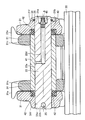
- the anti-rotation pin 25 is press-fitted into the insertion hole 22b of the master pin 22 through the groove 31b. Both ends of the press-fitted anti-rotation pin 25 are accommodated in the groove 31b.
- the groove 31b has a width smaller than the diameter of the master pin 22. For this reason, when the master pin 22 rotates, the detent pin 25 is locked to the side wall of the groove 31b.
- the groove 31 b is formed in parallel with the tread surface 31 e of the second crawler belt link 31. In this shape, the length of the groove 31b can be formed longer than the case where the groove 31b is formed perpendicular to the tread surface 31e.
- the groove 31b has a width equal to or larger than the diameter of the detent pin 25.
- the anti-rotation pin 25 is disposed at the center of the master pin 22. In other words, the central axis B of the locking pin 25 is arranged so as to overlap the central axis A of the master pin 22.
- the groove 31b has an arc-shaped bottom surface that follows the cylindrical shape of the detent pin 25.
- the groove 31b has a taper that increases the opening area toward the surface of the link boss portion 31f. This taper may be a short taper by chamfering.
- the depth of the groove 31b is larger than the diameter of the rotation prevention pin 25.
- the detent pin 25 is disposed in the groove 31b.
- the anti-rotation pin 25 has a cylindrical shape and is engaged with the arc-shaped bottom surface of the groove 31b.
- the anti-rotation pin 25 is disposed at the center in the length direction of the groove 31b. That is, the detent pin 25 does not protrude outside the groove 31b from both ends in the length direction of the groove 31b.
- the diameter of the central portion 25a of the rotation preventing pin 25 is smaller than the diameter of both side portions 25b sandwiching the central portion 25a.
- the outer diameter of the central portion 25a is set to a diameter that is an intermediate fit with respect to the inner diameter of the insertion hole 22b.
- the outer diameter of both side portions 25b is set to a diameter that provides an interference fit with the inner diameter of the insertion hole 22b.
- the locking pin 25 is press-fitted into the insertion hole 22 b of the master pin 22. In a state where the rotation prevention pin 25 is attached to the master pin 22, the center portion 25a of the rotation prevention pin 25 is in the insertion hole 22b with an intermediate fit. Both side portions 25b of the locking pin 25 are outside the insertion hole 22b.
- the anti-rotation pin 25 having this shape is difficult to drop off from the master pin 22.
- the detent pin 25 is displaced from the center of the master pin 22 toward the crawler plate mounting surface.
- the center axis B of the locking pin 25 is shifted from the center axis A of the master pin 22 by the offset amount S toward the shoeboard mounting surface.
- a plurality of detent pins 25 may be provided.
- the two anti-rotation pins 25 may be arranged so as to be shifted from the center of the master pin 22 to the crawler plate mounting surface side and the tread surface side, respectively.
- the master pin 22 is pulled out by the following procedure. First, the C-shaped notch of the snap ring 26 is widened to remove the snap ring 26 from the circumferential groove 22c. Then, the snap ring 26 is removed from the master pin 22 by removing the snap ring 26 from the end of the master pin 22. In this state, the master pin 22 is pulled out to the second crawler belt link side. Thereby, the connection of the crawler belt coupling device is released.
- the crawler belt connecting device when connecting the crawler belt connecting device again, it can be connected in the reverse procedure to that described above. That is, in the crawler belt coupling apparatus of the present embodiment, the master pin 22 can be attached to and detached from the first crawler belt link 21 and the second crawler belt link 31 by detaching the snap ring 26. Therefore, since the crawler belt 10 can be connected and released without using a press machine, the workability of attaching / detaching the crawler belt 10 can be improved.
- the detent pin 25 is press-fitted into an insertion hole 22 b formed in the master pin 22, and both ends protrude from the master pin 22.
- the groove 31 b is formed on the end surface of the second crawler belt link 31 opposite to the first crawler belt link 21 and has a width smaller than the diameter of the master pin 22.
- the rotation prevention pin 25 is arrange
- the present invention can be applied particularly advantageously to a crawler belt coupling device having a master pin.
Landscapes
- Engineering & Computer Science (AREA)
- Chemical & Material Sciences (AREA)
- Combustion & Propulsion (AREA)
- Transportation (AREA)
- Mechanical Engineering (AREA)
- Jib Cranes (AREA)
- Hand Tools For Fitting Together And Separating, Or Other Hand Tools (AREA)
- Transmissions By Endless Flexible Members (AREA)
Abstract
Description
まず本発明の一実施の形態における油圧ショベルの構成について説明する。以下、本発明の思想を適用可能な装軌式作業車両の一例である油圧ショベルについて説明するが、本発明はブルドーザなどの油圧ショベル以外の装軌式作業車両にも適用可能である。
再び図4および図5を参照して、本実施の形態の履帯連結装置では、マスタピン22が第1の履帯リンク21および第2の履帯リンク31ならびに第1の履帯リンク21および第2の履帯リンク31に隣接する一方の履帯リンク20aから引き抜かれることにより、連結が解除される。
本実施の形態の履帯連結装置によれば、スナップリング26がC型形状を有しているためスナップリング26をマスタピン22に容易に脱着することができる。スナップリング26を脱着することでマスタピン22を第1および第2の履帯リンク21、31に脱着することができる。したがって、プレス機を用いずに第1および第2の履帯リンク21、31にマスタピン22を脱着することができる。よって、履帯10の脱着の作業性を向上することができる。
Claims (6)
- 第1の貫通孔を有する第1の履帯リンクと、
前記第1の履帯リンクと対向して配置され、第2の貫通孔を有し、かつ前記第1の履帯リンクと反対側の端面に形成された溝を有する第2の履帯リンクと、
前記第1および第2の貫通孔に挿入されたマスタピンとを備え、
前記マスタピンには、前記マスタピンの径方向に貫通する挿入孔が形成されており、さらに、
前記挿入孔に圧入され、かつ前記マスタピンから両端が突き出した回り止めピンと、
C型形状を有し、前記第1の貫通孔よりも大きな外径を有し、前記第1の貫通孔に対して前記第2の履帯リンクと反対側に位置し、かつ前記マスタピンに取り付けられたスナップリングとを備え、
前記溝は前記マスタピンの径よりも小さい幅を有し、
前記回り止めピンは前記溝内に配置されている、履帯連結装置。 - 前記マスタピンは前記第1および第2の貫通孔に中間嵌めで係合する、請求項1に記載の履帯連結装置。
- 前記回り止めピンは円柱形状であり、
前記溝は前記円柱形状に沿う半円状の底面を有している、請求項1または2に記載の履帯連結装置。 - 前記回り止めピンの中央部の径は前記中央部を挟む両側部の径よりも小さい、請求項1~3のいずれか1項に記載の履帯連結装置。
- 前記回り止めピンは前記溝の長さ方向の中央に配置される、請求項1~4のいずれか1項に記載の履帯連結装置。
- 前記第2の履帯リンクは踏面とリンクボス部とを含み、
前記溝は前記踏面と平行に前記リンクボス部に形成されている、請求項1~5のいずれか1項に記載の履帯連結装置。
Priority Applications (5)
| Application Number | Priority Date | Filing Date | Title |
|---|---|---|---|
| KR1020157013110A KR101733330B1 (ko) | 2013-03-06 | 2013-08-21 | 크롤러 벨트 연결 장치 |
| DE112013006771.4T DE112013006771B4 (de) | 2013-03-06 | 2013-08-21 | Raupenband-Koppeleinrichtung |
| CN201380002879.7A CN104159810B (zh) | 2013-03-06 | 2013-08-21 | 履带连结装置 |
| US14/376,882 US9630665B2 (en) | 2013-03-06 | 2013-08-21 | Crawler belt coupling apparatus |
| IN4013DEN2015 IN2015DN04013A (ja) | 2013-03-06 | 2015-05-12 |
Applications Claiming Priority (2)
| Application Number | Priority Date | Filing Date | Title |
|---|---|---|---|
| JP2013043880A JP5775894B2 (ja) | 2013-03-06 | 2013-03-06 | 履帯連結装置 |
| JP2013-043880 | 2013-03-06 |
Publications (1)
| Publication Number | Publication Date |
|---|---|
| WO2014136290A1 true WO2014136290A1 (ja) | 2014-09-12 |
Family
ID=51490838
Family Applications (1)
| Application Number | Title | Priority Date | Filing Date |
|---|---|---|---|
| PCT/JP2013/072246 Ceased WO2014136290A1 (ja) | 2013-03-06 | 2013-08-21 | 履帯連結装置 |
Country Status (7)
| Country | Link |
|---|---|
| US (1) | US9630665B2 (ja) |
| JP (1) | JP5775894B2 (ja) |
| KR (1) | KR101733330B1 (ja) |
| CN (1) | CN104159810B (ja) |
| DE (1) | DE112013006771B4 (ja) |
| IN (1) | IN2015DN04013A (ja) |
| WO (1) | WO2014136290A1 (ja) |
Cited By (2)
| Publication number | Priority date | Publication date | Assignee | Title |
|---|---|---|---|---|
| US11565761B2 (en) | 2019-02-06 | 2023-01-31 | Caterpillar Inc. | Track joint assembly in machine track having pin stop for cartridge pin retention |
| WO2025109871A1 (ja) * | 2023-11-21 | 2025-05-30 | 株式会社小松製作所 | 履帯連結装置 |
Families Citing this family (7)
| Publication number | Priority date | Publication date | Assignee | Title |
|---|---|---|---|---|
| CN107848586B (zh) * | 2015-07-10 | 2021-05-28 | 意大利农用机贸易股份公司 | 链条接头组件 |
| US10189518B2 (en) | 2016-10-17 | 2019-01-29 | Caterpillar Inc. | Track nut with increased bearing area |
| USD818810S1 (en) | 2016-10-17 | 2018-05-29 | Caterpillar Inc. | Track nut |
| EP3717335B1 (en) * | 2017-11-27 | 2022-03-02 | Italtractor ITM S.p.A. | Connection assembly for articulated chains |
| US10981612B2 (en) * | 2018-08-22 | 2021-04-20 | Caterpillar Inc. | Flanged master track pin with retaining ring |
| CN114488276B (zh) * | 2020-10-23 | 2025-11-25 | 中国石油化工股份有限公司 | 面向不同应用场景的地震传感器快速筛选方法及系统 |
| US11964711B2 (en) * | 2021-07-28 | 2024-04-23 | Caterpillar Inc. | Track link in track link assembly having guide protrusion |
Citations (8)
| Publication number | Priority date | Publication date | Assignee | Title |
|---|---|---|---|---|
| JPS5292115A (en) * | 1976-01-30 | 1977-08-03 | Hitachi Ltd | Fan putting on and off equipment |
| JPS58190277U (ja) * | 1982-06-14 | 1983-12-17 | 三菱重工業株式会社 | 装軌車両の履帯 |
| JPS58190278U (ja) * | 1982-06-14 | 1983-12-17 | 三菱重工業株式会社 | 装軌車両の履帯連結用マスタピン抜止め装置 |
| JPS6216394Y2 (ja) * | 1981-04-09 | 1987-04-24 | ||
| JPS641078U (ja) * | 1988-02-19 | 1989-01-06 | ||
| JPH0364839B2 (ja) * | 1985-05-15 | 1991-10-08 | Seikosha Kk | |
| JPH0641265B2 (ja) * | 1985-02-08 | 1994-06-01 | 日立建機株式会社 | 履 帯 |
| JPH08295268A (ja) * | 1995-04-28 | 1996-11-12 | Hitachi Constr Mach Co Ltd | トラックリンクのマスタピン抜け止め装置 |
Family Cites Families (19)
| Publication number | Priority date | Publication date | Assignee | Title |
|---|---|---|---|---|
| US1983548A (en) * | 1933-02-06 | 1934-12-11 | Harry A Knox | Track for tracklaying vehicles |
| US2430573A (en) * | 1943-12-31 | 1947-11-11 | Goodrich Co B F | Cushioned connection |
| US2988926A (en) * | 1958-07-28 | 1961-06-20 | Gen Motors Corp | Master link |
| US3027201A (en) * | 1959-12-08 | 1962-03-27 | Lempco Products Inc | Master pin for articulated tracks |
| US3013844A (en) * | 1960-05-18 | 1961-12-19 | Gen Motors Corp | Master pin |
| DE1821189U (de) | 1960-09-15 | 1960-11-03 | Sybille Dohle | Laufwerk fuer gleiskettenfahrzeuge. |
| US3169039A (en) * | 1964-06-24 | 1965-02-09 | Case Co J I | Track chain |
| JPS489444Y1 (ja) * | 1968-10-04 | 1973-03-13 | ||
| US4150856A (en) * | 1977-11-25 | 1979-04-24 | Caterpillar Tractor Co. | One-piece track pin |
| JPS5493641U (ja) * | 1977-12-15 | 1979-07-03 | ||
| US4277199A (en) * | 1979-03-23 | 1981-07-07 | Caterpillar Tractor Co. | Keeper assembly |
| JP4298180B2 (ja) * | 2001-03-16 | 2009-07-15 | 株式会社小松製作所 | 履帯のリンクとピンとの固定構造 |
| US7766433B2 (en) | 2006-09-22 | 2010-08-03 | Deere & Company | Cartridge for use as joint in endless track chain and associated method |
| ITMI20070147A1 (it) * | 2007-01-30 | 2008-07-31 | Berco Spa | Sistema di tenuta per giunto di cingolatura |
| US20080265667A1 (en) * | 2007-04-24 | 2008-10-30 | Livesay Richard E | Bolt together machine track and method |
| CN101544248B (zh) * | 2008-03-21 | 2011-08-10 | 董明国 | 密封润滑式履带及履带的连接方法 |
| IT1399166B1 (it) * | 2009-03-24 | 2013-04-11 | Berco Spa | Catena a boccole rotanti per veicoli cingolati |
| IT1393533B1 (it) * | 2009-03-24 | 2012-04-27 | Berco Spa | Catena a boccole rotanti per veicoli cingolati con cuscinetti a strisciamento migliorati |
| DE102009020906B4 (de) | 2009-05-12 | 2011-05-05 | Diehl Remscheid Gmbh & Co.Kg | Verbindungsvorrichtung |
-
2013
- 2013-03-06 JP JP2013043880A patent/JP5775894B2/ja not_active Expired - Fee Related
- 2013-08-21 WO PCT/JP2013/072246 patent/WO2014136290A1/ja not_active Ceased
- 2013-08-21 US US14/376,882 patent/US9630665B2/en not_active Expired - Fee Related
- 2013-08-21 CN CN201380002879.7A patent/CN104159810B/zh not_active Expired - Fee Related
- 2013-08-21 KR KR1020157013110A patent/KR101733330B1/ko not_active Expired - Fee Related
- 2013-08-21 DE DE112013006771.4T patent/DE112013006771B4/de not_active Expired - Fee Related
-
2015
- 2015-05-12 IN IN4013DEN2015 patent/IN2015DN04013A/en unknown
Patent Citations (8)
| Publication number | Priority date | Publication date | Assignee | Title |
|---|---|---|---|---|
| JPS5292115A (en) * | 1976-01-30 | 1977-08-03 | Hitachi Ltd | Fan putting on and off equipment |
| JPS6216394Y2 (ja) * | 1981-04-09 | 1987-04-24 | ||
| JPS58190277U (ja) * | 1982-06-14 | 1983-12-17 | 三菱重工業株式会社 | 装軌車両の履帯 |
| JPS58190278U (ja) * | 1982-06-14 | 1983-12-17 | 三菱重工業株式会社 | 装軌車両の履帯連結用マスタピン抜止め装置 |
| JPH0641265B2 (ja) * | 1985-02-08 | 1994-06-01 | 日立建機株式会社 | 履 帯 |
| JPH0364839B2 (ja) * | 1985-05-15 | 1991-10-08 | Seikosha Kk | |
| JPS641078U (ja) * | 1988-02-19 | 1989-01-06 | ||
| JPH08295268A (ja) * | 1995-04-28 | 1996-11-12 | Hitachi Constr Mach Co Ltd | トラックリンクのマスタピン抜け止め装置 |
Cited By (2)
| Publication number | Priority date | Publication date | Assignee | Title |
|---|---|---|---|---|
| US11565761B2 (en) | 2019-02-06 | 2023-01-31 | Caterpillar Inc. | Track joint assembly in machine track having pin stop for cartridge pin retention |
| WO2025109871A1 (ja) * | 2023-11-21 | 2025-05-30 | 株式会社小松製作所 | 履帯連結装置 |
Also Published As
| Publication number | Publication date |
|---|---|
| DE112013006771T5 (de) | 2015-12-24 |
| US9630665B2 (en) | 2017-04-25 |
| IN2015DN04013A (ja) | 2015-06-26 |
| CN104159810A (zh) | 2014-11-19 |
| DE112013006771B4 (de) | 2018-09-06 |
| JP2014172418A (ja) | 2014-09-22 |
| KR101733330B1 (ko) | 2017-05-08 |
| US20160221619A1 (en) | 2016-08-04 |
| CN104159810B (zh) | 2016-06-15 |
| KR20150075104A (ko) | 2015-07-02 |
| JP5775894B2 (ja) | 2015-09-09 |
Similar Documents
| Publication | Publication Date | Title |
|---|---|---|
| JP5775894B2 (ja) | 履帯連結装置 | |
| JP5247913B1 (ja) | 履帯連結装置 | |
| JP5270042B2 (ja) | 履帯と履帯のためのマスタリンク | |
| JP5230836B1 (ja) | 履帯用リンクおよび履帯装置 | |
| US9840291B2 (en) | Roller device for track-type work vehicle, roller shell unit and roller shell | |
| KR101138913B1 (ko) | 크롤러 벨트 | |
| US20160236735A1 (en) | Roller device and roller shell for track-type work vehicle | |
| US9555845B2 (en) | Roller device for track-type work vehicle | |
| JP6721604B2 (ja) | 走行体および作業車両 | |
| US20140333125A1 (en) | Sprocket with replaceable teeth | |
| JP3904428B2 (ja) | 装軌式車両の走行駆動装置 | |
| JP2015151080A (ja) | 作業機の無限軌道帯 | |
| WO2025109871A1 (ja) | 履帯連結装置 | |
| JP2004168094A (ja) | 無限軌条走行体の駆動装置 |
Legal Events
| Date | Code | Title | Description |
|---|---|---|---|
| WWE | Wipo information: entry into national phase |
Ref document number: 14376882 Country of ref document: US |
|
| 121 | Ep: the epo has been informed by wipo that ep was designated in this application |
Ref document number: 13876938 Country of ref document: EP Kind code of ref document: A1 |
|
| ENP | Entry into the national phase |
Ref document number: 20157013110 Country of ref document: KR Kind code of ref document: A |
|
| WWE | Wipo information: entry into national phase |
Ref document number: 112013006771 Country of ref document: DE Ref document number: 1120130067714 Country of ref document: DE |
|
| 122 | Ep: pct application non-entry in european phase |
Ref document number: 13876938 Country of ref document: EP Kind code of ref document: A1 |