WO2014132691A1 - 偏光板、偏光板の製造方法及び液晶表示装置 - Google Patents
偏光板、偏光板の製造方法及び液晶表示装置 Download PDFInfo
- Publication number
- WO2014132691A1 WO2014132691A1 PCT/JP2014/050635 JP2014050635W WO2014132691A1 WO 2014132691 A1 WO2014132691 A1 WO 2014132691A1 JP 2014050635 W JP2014050635 W JP 2014050635W WO 2014132691 A1 WO2014132691 A1 WO 2014132691A1
- Authority
- WO
- WIPO (PCT)
- Prior art keywords
- film
- protective film
- polarizing plate
- acid
- cellulose ester
- Prior art date
- Legal status (The legal status is an assumption and is not a legal conclusion. Google has not performed a legal analysis and makes no representation as to the accuracy of the status listed.)
- Ceased
Links
Images


Classifications
-
- G—PHYSICS
- G02—OPTICS
- G02B—OPTICAL ELEMENTS, SYSTEMS OR APPARATUS
- G02B5/00—Optical elements other than lenses
- G02B5/30—Polarising elements
- G02B5/3025—Polarisers, i.e. arrangements capable of producing a definite output polarisation state from an unpolarised input state
- G02B5/3033—Polarisers, i.e. arrangements capable of producing a definite output polarisation state from an unpolarised input state in the form of a thin sheet or foil, e.g. Polaroid
-
- B—PERFORMING OPERATIONS; TRANSPORTING
- B32—LAYERED PRODUCTS
- B32B—LAYERED PRODUCTS, i.e. PRODUCTS BUILT-UP OF STRATA OF FLAT OR NON-FLAT, e.g. CELLULAR OR HONEYCOMB, FORM
- B32B23/00—Layered products comprising a layer of cellulosic plastic substances, i.e. substances obtained by chemical modification of cellulose, e.g. cellulose ethers, cellulose esters, viscose
- B32B23/04—Layered products comprising a layer of cellulosic plastic substances, i.e. substances obtained by chemical modification of cellulose, e.g. cellulose ethers, cellulose esters, viscose comprising such cellulosic plastic substance as the main or only constituent of a layer, which is next to another layer of the same or of a different material
- B32B23/08—Layered products comprising a layer of cellulosic plastic substances, i.e. substances obtained by chemical modification of cellulose, e.g. cellulose ethers, cellulose esters, viscose comprising such cellulosic plastic substance as the main or only constituent of a layer, which is next to another layer of the same or of a different material of synthetic resin
-
- B—PERFORMING OPERATIONS; TRANSPORTING
- B32—LAYERED PRODUCTS
- B32B—LAYERED PRODUCTS, i.e. PRODUCTS BUILT-UP OF STRATA OF FLAT OR NON-FLAT, e.g. CELLULAR OR HONEYCOMB, FORM
- B32B23/00—Layered products comprising a layer of cellulosic plastic substances, i.e. substances obtained by chemical modification of cellulose, e.g. cellulose ethers, cellulose esters, viscose
- B32B23/20—Layered products comprising a layer of cellulosic plastic substances, i.e. substances obtained by chemical modification of cellulose, e.g. cellulose ethers, cellulose esters, viscose comprising esters
-
- B—PERFORMING OPERATIONS; TRANSPORTING
- B32—LAYERED PRODUCTS
- B32B—LAYERED PRODUCTS, i.e. PRODUCTS BUILT-UP OF STRATA OF FLAT OR NON-FLAT, e.g. CELLULAR OR HONEYCOMB, FORM
- B32B27/00—Layered products comprising a layer of synthetic resin
- B32B27/32—Layered products comprising a layer of synthetic resin comprising polyolefins
- B32B27/325—Layered products comprising a layer of synthetic resin comprising polyolefins comprising polycycloolefins
-
- B—PERFORMING OPERATIONS; TRANSPORTING
- B32—LAYERED PRODUCTS
- B32B—LAYERED PRODUCTS, i.e. PRODUCTS BUILT-UP OF STRATA OF FLAT OR NON-FLAT, e.g. CELLULAR OR HONEYCOMB, FORM
- B32B7/00—Layered products characterised by the relation between layers; Layered products characterised by the relative orientation of features between layers, or by the relative values of a measurable parameter between layers, i.e. products comprising layers having different physical, chemical or physicochemical properties; Layered products characterised by the interconnection of layers
- B32B7/04—Interconnection of layers
- B32B7/12—Interconnection of layers using interposed adhesives or interposed materials with bonding properties
-
- G—PHYSICS
- G02—OPTICS
- G02B—OPTICAL ELEMENTS, SYSTEMS OR APPARATUS
- G02B1/00—Optical elements characterised by the material of which they are made; Optical coatings for optical elements
- G02B1/10—Optical coatings produced by application to, or surface treatment of, optical elements
- G02B1/14—Protective coatings, e.g. hard coatings
-
- B—PERFORMING OPERATIONS; TRANSPORTING
- B32—LAYERED PRODUCTS
- B32B—LAYERED PRODUCTS, i.e. PRODUCTS BUILT-UP OF STRATA OF FLAT OR NON-FLAT, e.g. CELLULAR OR HONEYCOMB, FORM
- B32B2307/00—Properties of the layers or laminate
- B32B2307/40—Properties of the layers or laminate having particular optical properties
- B32B2307/42—Polarizing, birefringent, filtering
-
- B—PERFORMING OPERATIONS; TRANSPORTING
- B32—LAYERED PRODUCTS
- B32B—LAYERED PRODUCTS, i.e. PRODUCTS BUILT-UP OF STRATA OF FLAT OR NON-FLAT, e.g. CELLULAR OR HONEYCOMB, FORM
- B32B2307/00—Properties of the layers or laminate
- B32B2307/50—Properties of the layers or laminate having particular mechanical properties
- B32B2307/536—Hardness
-
- B—PERFORMING OPERATIONS; TRANSPORTING
- B32—LAYERED PRODUCTS
- B32B—LAYERED PRODUCTS, i.e. PRODUCTS BUILT-UP OF STRATA OF FLAT OR NON-FLAT, e.g. CELLULAR OR HONEYCOMB, FORM
- B32B2457/00—Electrical equipment
- B32B2457/20—Displays, e.g. liquid crystal displays, plasma displays
- B32B2457/202—LCD, i.e. liquid crystal displays
-
- G02B1/105—
Definitions
- the present invention relates to a polarizing plate, a method for producing the same, and a liquid crystal display device including the polarizing plate. More specifically, a thin film polarizing plate constituted by laminating a thin cellulose ester film and a thin film polarizer using an ultraviolet curable adhesive, a manufacturing method thereof, and a liquid crystal display including the polarizing plate Relates to the device.
- a general configuration of a liquid crystal display device includes a liquid crystal cell in which a transparent electrode, a liquid crystal layer, a color filter, and the like are sandwiched between glass plates, and two polarizing plates provided on both sides thereof. Each polarizing plate is usually configured such that a polarizer is sandwiched between two transparent resin films.
- a cellulose ester film such as cellulose acetate is often used for the purpose of protecting the polarizer.
- the cellulose ester film has a high transmittance, and by immersing it in an alkaline aqueous solution to saponify its surface and make it hydrophilic, excellent adhesion to a polarizer is realized.
- a polarizing plate constituting the display is also required to be thin.
- the cellulose acetate film that is a protective film is thinned, there is a problem that the film strength and dimensional stability are reduced.
- the thickness is a thin film of 40 ⁇ m or less, Therefore, it is an obstacle to the realization of a thinner polarizing plate.
- a method for bonding a polarizer and a cellulose ester film using an ultraviolet curable adhesive is disclosed in order to simplify the manufacturing process of a polarizing plate by omitting the saponification step of the cellulose ester film.
- the polarizer polarizing film
- the polarizer is not easily decolorized even under severe environmental conditions such as high temperature and high humidity, and a highly durable polarizing plate can be obtained.
- part of the applied ultraviolet curable adhesive is a cellulose ester.
- unevenness of curing occurred in the ultraviolet curable adhesive layer when irradiated with ultraviolet rays, and that the entire surface of the cellulose ester film had high and low moisture permeability.
- the prepared polarizing plate is too thin, so that the rigidity as the polarizing plate is insufficient, and handling in the polarizing plate manufacturing process We had problems with sex.
- the present invention has been made in view of the above problems, and the problem to be solved is a polarizing plate composed of a cellulose ester film and a polarizer as a protective film, and is exposed to a high temperature and high humidity environment for a long time.
- a polarizing plate of a thin film with excellent deterioration resistance (image unevenness resistance, adhesion durability) of the polarizer and improved handleability and thin film suitability at the time of manufacture, a manufacturing method thereof, and a liquid crystal display provided with the polarizing plate Is to provide a device.
- the present inventor is a polarizing plate having a protective film A, a polarizer, and a protective film B in this order
- the protective film A is a cellulose ester film
- the cellulose ester film (1) Contains cellulose acetate having an average degree of acetyl group substitution in a specific range as a main component, (2) has a thin film configuration having a film thickness in the range of 15 to 40 ⁇ m, and (3) has a Martens hardness of 1 ⁇ m in measurement depth.
- the average value in the width direction is within a specific numerical range, and the variation width of the Martens hardness coefficient in the width direction is 10.0% or less.
- the protective film A is a cellulose ester film
- the cellulose ester film is (1) containing cellulose acetate having an average degree of acetyl group substitution in the range of 2.60 to 2.95 as a main component; (2)
- the film thickness is in the range of 15-40 ⁇ m, (3)
- the average value in the width direction of the Martens hardness at a measurement depth of 1 ⁇ m is in the range of 140 to 230 N / mm 2 , and the variation coefficient of the Martens hardness in the width direction is 10.0% or less
- the cellulose-ester film which is the said protective film A, and the at least one surface of the said polarizer are bonded by the ultraviolet curable adhesive.
- the polarizing plate characterized by the above-mentioned.
- the coefficient of variation of the Martens hardness in the width direction of the cellulose ester film that is the protective film A is 5.0% or less.
- An embossed portion having a height from the bottom surface of the film within a range of 1 to 20 ⁇ m is formed in a region within 5% of the length of the film width from both ends in the width direction of the cellulose ester film as the protective film A.
- the height of the convex portion of the embossed portion after being stored for 10 minutes under a load of 1 kg in a circular region having a diameter of 5 mm on the surface of the embossed portion in an environment of 23 ° C. and 55% RH
- D is the height and D 0 is the height of the convex portion of the embossed portion before the load is applied
- the embossing crush resistance (%) defined by the following formula (1) is 50 for both embossed portions at both ends. % Or more,
- Embossing crush resistance (%) D / D 0 ⁇ 100 (%) 4).
- the cellulose ester film as the protective film A is 1) sugar ester, 2) polycondensate of dicarboxylic acid and diol, 3) phosphate ester compound, 4) esters of aliphatic polyhydric alcohol and monocarboxylic acid, And 5)
- a film thickness of the cellulose ester film as the protective film A is in a range of 15 to 30 ⁇ m.
- a film thickness of the polarizer is in a range of 2 to 15 ⁇ m.
- the protective film A is a cellulose ester film
- the cellulose ester film is (1) containing cellulose acetate having an average degree of acetyl group substitution in the range of 2.60 to 2.95 as a main component; (2) The film thickness is in the range of 15-40 ⁇ m, (3) The average value in the width direction of the Martens hardness at a measurement depth of 1 ⁇ m is in the range of 140 to 230 N / mm 2 , and the variation coefficient of the Martens hardness in the width direction is 10% or less
- the cellulose ester film as the protective film A is produced using at least one production condition selected from the following conditions 1 to 3;
- the polarizing plate is produced by bonding a cellulose ester film as the protective film A and at least one surface of the polarizer using an ultraviolet curable adhesive. Production method.
- Condition 1 Forming the cellulose ester film by forming a film using a dope having an alcohol concentration in the range of 0.5 to 4.0% by mass.
- the cellulose ester film is produced by performing a stretching treatment under the condition that the amount of residual solvent in the film is in the range of 0.5 to 4.0% by mass.
- the cellulose ester film is produced by subjecting the roll laminate of the cellulose ester film to an aging treatment for 3 days or more under the condition of 50 ° C. or more.
- the protective film B constituting the polarizing plate is a retardation film, and the polarizer and the retardation film that is the protective film B are bonded and manufactured using an ultraviolet curable adhesive.
- a liquid crystal display device comprising the polarizing plate according to any one of items 1 to 11.
- a thin film having excellent polarizer deterioration resistance image unevenness resistance, adhesion durability
- image unevenness resistance, adhesion durability image unevenness resistance, adhesion durability
- FIG. 1 Schematic sectional view showing an example of the configuration of the polarizing plate of the present invention
- Partial sectional drawing which shows an example of the embossed part vicinity of the cellulose-ester film which is the protective film A which concerns on this invention
- Partial sectional view showing an example of an embossed part in the measurement of the anti-embossing crush rate
- the schematic perspective view which shows an example of the measuring method of the embossing crushing rate of the convex part of an embossed part
- the polarizing plate of this invention has the structure which laminated
- the said protective film A is a cellulose-ester film,
- the said cellulose-ester film is (1) average acetyl. Contains cellulose acetate as the main component with a degree of group substitution in the range of 2.60 to 2.95, (2) has a film thickness in the range of 15 to 40 ⁇ m, and (3) Martens hardness with a measurement depth of 1 ⁇ m.
- a cellulose ester film as the protective film A having an average value in the width direction of 140 to 230 N / mm 2 and a coefficient of variation of Martens hardness in the width direction of 10.0% or less; At least one surface of the polarizer is bonded with an ultraviolet curable adhesive.
- the coefficient of variation of the Martens hardness in the width direction of the cellulose ester film is further 5.0% or less, from the viewpoint that the effect intended by the present invention can be further expressed. preferable.
- the embossed portion having a height within the range of 1 to 20 ⁇ m from the bottom surface of the film in a region within 5% of the length of the width of the film from the both ends in the width direction of the cellulose ester film as the protective film A It is preferable from the viewpoint of obtaining a highly uniform cellulose ester film that the embossing crushing rate (%) defined by the formula (1) is 50% or more for both embossed portions. .
- the cellulose ester film as the protective film A contains a polycondensate of dicarboxylic acid and diol, and the carbon number of the dicarboxylic acid is more preferably 8 or more.
- the cellulose ester film as the protective film A is composed of 1) sugar ester, 2) polycondensate of dicarboxylic acid and diol, 3) phosphate ester compound, 4) ester of aliphatic polyhydric alcohol and monocarboxylic acid. And 5) at least three compounds selected from esters of glycolic acid.
- the retardation film which is B is comprised from the cycloolefin polymer.
- the retardation film as the protective film B and at least one surface of the polarizer are bonded with an ultraviolet curable adhesive.
- the protective film A is a cellulose ester film
- the average acetyl group substitution degree of the said cellulose ester film is 2.60.
- the average value in the direction is in the range of 140 to 230 N / mm 2
- the variation coefficient of Martens hardness in the width direction is 10% or less
- the cellulose ester film as the protective film A has the conditions 1 to Manufactured using at least one manufacturing condition selected from Condition 3
- the polarizing plate is the protective film A
- at least one surface of a cellulose ester film and the polarizer that is characterized by producing bonded combined and using an ultraviolet curing adhesive.
- the cellulose ester film as the protective film A was produced under the production conditions satisfying all of the above conditions 1 to 3, or the polarizing plate further has a retardation film as the protective film B, It is a preferable aspect that the polarizer and the retardation film are bonded and manufactured using an ultraviolet curable adhesive.
- the present inventor has a polarizing plate formed by laminating a protective film A, a polarizer and a protective film B in this order, and more specifically, a thin film polarizer which is a thin film polarizer and a protective film A.
- a polarizing plate formed by laminating a protective film A, a polarizer and a protective film B in this order, and more specifically, a thin film polarizer which is a thin film polarizer and a protective film A.
- the present inventors have found that the ultraviolet curable adhesive penetrates the cellulose acetate film. This phenomenon occurs when the surface hardness of the cellulose acetate film is low, and in addition, the bonding force with the ultraviolet curable adhesive on the surface is insufficient, and as a result, the ultraviolet curable adhesive and the cellulose acetate It has been found that the bonding strength between the films is reduced, and unevenness occurs in the adhesive strength. It was speculated that this phenomenon caused the above problem, that is, the deterioration of the polarizer when exposed to a high temperature and high humidity environment for a long time.
- the film hardness (Martens hardness) is controlled to be within a certain range, and the fluctuation (fluctuation) of the film hardness within the film plane. It has been found that the above-mentioned problems can be solved by applying a cellulose acetate film with a reduced coefficient. In addition, by making the Martens hardness of the cellulose acetate film within a certain range and suppressing the fluctuation of the film hardness in the film surface, the produced polarizing plate is not easily bent and the handling property is improved. did it.
- a desired range of Martens hardness can be obtained by reducing the residual solvent of the web during stretching in the cellulose acetate film forming step. It has been found that the Martens hardness is further increased by stretching in a state where the residual solvent amount of the web is small.
- the film is laminated and wound up in a roll shape, and the outer peripheral portion of the laminated roll is subjected to moisture-proof hermetically sealed packaging, followed by a high temperature environment of 50 to 60 ° C.
- a high temperature environment 50 to 60 ° C.
- the embossing resistance against embossing is a characteristic of the embossed portion provided in the vicinity of both ends of the roll-shaped cellulose acetate film. Is within a specific range, the hardness of the embossed part formed is increased, and even when a long cellulose acetate film is laminated in a roll shape, it becomes difficult to cause crushing due to the lamination of the embossed part.
- the cellulose acetate films in the laminated state are less likely to stick to each other, and the aging treatment which is the third method can be performed under more uniform conditions.
- a cellulose acetate film having a specific range of Martens hardness, a low coefficient of variation of Martens hardness, and high homogeneity can be obtained.
- the entire adhesive surface is bonded to a polarizer via an ultraviolet curable adhesive.
- an ultraviolet curable adhesive As a result of the high homogeneity, it has been found that there is no place where the moisture permeation resistance is excessive or insufficient over the entire surface, the surface becomes uniform, and the degree of polarization does not deteriorate over the entire surface.
- the handleability as a polarizing plate is improved by increasing the uniformity of the hardness of the cellulose acetate film.
- a retardation film as the protective film B more specifically, a cycloolefin polymer film, from the viewpoint of moisture resistance or the like with respect to the cellulose ester film as the protective film A.
- the cycloolefin polymer film cannot be bonded with water (polyvinyl alcohol adhesive) after saponification, so the polarizer and the retardation film, which is the protective film B, are UV-cured. It is effective to use a mold adhesive.
- the ultraviolet curable adhesive used by bonding with the cellulose acetate film which is the protective film A, and a polarizer, and the ultraviolet curable adhesive used by bonding with the retardation film which is a polarizer and the protective film B and From the viewpoint of being able to form an adhesive layer having the same behavior, stable characteristics, and excellent production efficiency, it is preferable to use the same type of ultraviolet curable adhesive.
- ⁇ is used to mean that the numerical values described before and after it are included as the lower limit value and the upper limit value.
- the polarizing plate of the present invention has a configuration in which a protective film A, a polarizer and a protective film B are laminated in this order.
- the protective film A is a cellulose ester film (cellulose acetate film), and the cellulose ester film (cellulose acetate film). ) And a polarizer are bonded via an ultraviolet curable adhesive.
- FIG. 1 is a schematic cross-sectional view showing an example of the configuration of the polarizing plate of the present invention.
- a polarizing plate 101 of the present invention has a cellulose acetate film 102 as a protective film A and a polarizer 104 from the surface side.
- the cellulose acetate film 102 and the polarizer 104 are composed of an ultraviolet curable adhesive. Bonded by layer 103A.
- the UV curable adhesive layer 103A is made of a material that is cured by irradiating ultraviolet rays or the like. Details of the ultraviolet curable adhesive will be described later.
- the surface of the polarizer 104 opposite to the surface on which the cellulose acetate film 102 as the protective film A is disposed is further protected via an ultraviolet curable adhesive layer 103B.
- a retardation film 105 having a specific retardation value is laminated.
- an antiglare layer for example, an antiglare layer, an antireflection layer, an antifouling layer, a hard coat layer, etc.
- the functional layer may be provided on the further outer side (outermost surface portion) of the cellulose ester film 102.
- the cellulose acetate used for forming the protective film A according to the present invention is triacetyl cellulose (abbreviation: TAC) having an average degree of acetyl group substitution in the range of 2.60 to 2.95. Furthermore, the average degree of acetyl group substitution is preferably in the range of 2.80 to 2.94. The degree of acetyl group substitution in the cellulose ester can be determined by measurement according to ASTM-D817-96.
- the average degree of acetyl group substitution of the cellulose acetate to be applied is 2.60 or more, it is possible to obtain characteristics such as high casting suitability during film formation and excellent handleability as a film. it can.
- the film thickness of the cellulose ester film according to the present invention is characterized by being in the range of 15 to 40 ⁇ m, more preferably in the range of 15 to 30 ⁇ m. If the film thickness of the cellulose ester film is 15 ⁇ m or more, sufficient rigidity can be obtained and excellent handling properties can be obtained, and if it is 40 ⁇ m or less, it can contribute to the production of a thin film polarizing plate.
- the number average molecular weight (Mn) of the triacetyl cellulose is preferably in the range of 125000 to 155000, and more preferably in the range of 129000 to 152000.
- the weight average molecular weight (Mw) is preferably in the range of 265,000 to 310000.
- the ratio (Mw / Mn) of the weight average molecular weight (Mw) to the number average molecular weight (Mn) is preferably in the range of 1.9 to 2.1.
- the average molecular weight (Mn, Mw) referred to in the present invention can be measured by gel permeation chromatography.
- the measurement conditions are as follows.
- the Martens hardness at a measurement depth of 1 ⁇ m of the cellulose ester film (cellulose acetate film) as the protective film A the average value in the width direction is in the range of 140 to 230 N / mm 2 and the width
- the coefficient of variation of Martens hardness in the hand direction is 10.0% or less.
- the Martens hardness according to the present invention can be measured by, for example, a method based on ISO145757-1 (* 1).
- the Martens hardness according to the present invention (also referred to as Martens hardness) is an index indicating the degree of hardness by the “load” required to scratch a measurement object with an indenter and create a dent of a certain depth. In the invention, it is obtained as a measured value at a depth of 1 ⁇ m.
- the Martens hardness according to the present invention is such that the Martens hardness on either the front or back side of the cellulose ester film (cellulose acetate film) is in the range of 140 to 230 N / mm 2 and the Martens hardness in the width direction.
- the Martens hardness at least on the side in contact with the ultraviolet adhesive is in the range specified above.
- Martens hardness F /
- the Martens hardness according to the present invention can be measured using, for example, a dynamic ultra-micro hardness meter DUH-211S manufactured by Shimadzu Corporation.
- the width direction of the cellulose ester film (cellulose acetate film) referred to in the present invention is a step (also referred to as a TD direction) perpendicular to the transport direction (MD direction) in the step of forming a cellulose ester film.
- Variation coefficient of Martens hardness (%) (standard deviation of Martens hardness / average value of Martens hardness) ⁇ 100 Specifically, in the same manner as in the above method, the Martens hardness is measured at 20 locations or more, preferably 50 locations in the width direction, the average value of the Martens hardness, which is the arithmetic average value, and the standard of Martens hardness. It can be calculated by obtaining the deviation.
- the method for adjusting the average value and the coefficient of variation in the width direction of the Martens hardness of the cellulose ester film (cellulose acetate film) according to the present invention within the range defined in the present invention is not particularly limited. As described above, this can be achieved by appropriately selecting or combining the following methods. Although the method applicable to this invention is shown below, this invention is not restrict
- the hardness of the formed cellulose acetate film becomes constant in the in-plane direction, and the coefficient of variation Can be prepared to desired conditions.
- the Martens hardness defined in the present invention can be obtained by setting the residual solvent of the web at the time of stretching in the cellulose acetate film forming step.
- the film is wound in a state of being laminated in a roll shape, and the outer peripheral portion of the laminated roll is subjected to moisture-proof hermetically sealed packaging, followed by a high temperature of 50 to 60 ° C.
- This is a method of performing an aging process for 3 days or more in an environment.
- the fifth method the first method, the second method, and the fourth method described above are combined, and embossing is performed in the vicinity of both ends of the roll-shaped cellulose acetate film.
- the cellulose ester film (cellulose acetate film) according to the present invention preferably contains a polycondensate of dicarboxylic acid and diol.
- the inclusion of a polycondensate of a dicarboxylic acid and a diol is preferable from the viewpoint of improving the tear resistance of the film and making it possible to produce a film that does not easily break even when stretched.
- B represents an aliphatic or aromatic monocarboxylic acid residue.
- G represents an alkylene glycol residue having 2 to 12 carbon atoms, an aryl glycol residue having 6 to 12 carbon atoms, or an oxyalkylene glycol residue having 4 to 12 carbon atoms.
- A represents an alkylene dicarboxylic acid residue having 4 to 12 carbon atoms or an aryl dicarboxylic acid residue having 6 to 12 carbon atoms.
- n represents an integer of 1 or more.
- the polycondensate (polyester compound) according to the present invention is a polyester containing a repeating unit obtained by reacting a dicarboxylic acid and a diol, A represents a carboxylic acid residue in the ester, and G represents an alcohol residue. .
- the dicarboxylic acid constituting the polyester is an aromatic dicarboxylic acid, an aliphatic dicarboxylic acid or an alicyclic dicarboxylic acid, preferably an aromatic dicarboxylic acid.
- the dicarboxylic acid may be one type or a mixture of two or more types.
- the carbon number of the dicarboxylic acid constituting the polycondensate is preferably 8 or more.
- the diol constituting the polyester is an aromatic diol, an aliphatic diol or an alicyclic diol, preferably an aliphatic diol, more preferably a diol having 1 to 4 carbon atoms.
- the diol may be one type or a mixture of two or more types.
- Both ends of the molecule of the polyester may be sealed or not sealed, but from the viewpoint of reducing the retardation fluctuation of the cellulose ester film with respect to the temperature and humidity fluctuation, it may be sealed. preferable.
- alkylene dicarboxylic acid constituting A in the general formula (I) include, for example, 1,2-ethanedicarboxylic acid (succinic acid), 1,3-propanedicarboxylic acid (glutaric acid), 1,4-butane.
- Divalent groups derived from dicarboxylic acid (adipic acid), 1,5-pentanedicarboxylic acid (pimelic acid), 1,8-octanedicarboxylic acid (sebacic acid) and the like are included.
- alkenylene dicarboxylic acid constituting A include maleic acid and fumaric acid.
- aryl dicarboxylic acid constituting A examples include 1,2-benzenedicarboxylic acid (phthalic acid), 1,3-benzenedicarboxylic acid, 1,4-benzenedicarboxylic acid, 1,5-naphthalenedicarboxylic acid, and the like. Can be mentioned.
- G is a divalent group derived from an alkylene glycol having 2 to 12 carbon atoms, a divalent group derived from an aryl glycol having 6 to 12 carbon atoms, or a carbon number. Represents a divalent group derived from 4 to 12 oxyalkylene glycols.
- divalent groups derived from aryl glycols having 6 to 12 carbon atoms in G include 1,2-dihydroxybenzene (catechol), 1,3-dihydroxybenzene (resorcinol), 1,4-dihydroxybenzene And divalent groups derived from (hydroquinone).
- divalent group derived from oxyalkylene glycol having 4 to 12 carbon atoms in G are derived from diethylene glycol, triethylene glycol, tetraethylene glycol, dipropylene glycol, tripropylene glycol and the like. A divalent group is mentioned.
- G may be one type or two or more types may be combined. Among these, G is preferably an alkylene glycol having 2 to 12 carbon atoms.
- B in the general formula (I) is a monovalent group derived from an aromatic ring-containing monocarboxylic acid or an aliphatic monocarboxylic acid.
- the aromatic ring-containing monocarboxylic acid in the monovalent group derived from the aromatic ring-containing monocarboxylic acid is a carboxylic acid containing an aromatic ring in the molecule, and not only those in which the aromatic ring is directly bonded to a carboxy group, Also included are those in which an aromatic ring is bonded to a carboxy group via an alkylene group or the like.
- monovalent groups derived from aromatic ring-containing monocarboxylic acids include benzoic acid, para-tert-butyl benzoic acid, orthotoluic acid, metatoluic acid, p-toluic acid, dimethyl benzoic acid, ethyl benzoic acid, and normal propyl benzoic acid.
- the weight average molecular weight of the polyester according to the present invention is preferably in the range of 300 to 3000, and more preferably in the range of 400 to 2000.
- the weight average molecular weight can be measured by the gel permeation chromatography (GPC).
- polyester P1 180 g of ethylene glycol, 278 g of phthalic anhydride, 91 g of adipic acid, 610 g of benzoic acid, 0.191 g of tetraisopropyl titanate as an esterification catalyst, 2 liters equipped with a thermometer, a stirrer, and a slow cooling tube
- the mixture was added to a four-necked flask, gradually heated while being stirred in a nitrogen stream until reaching 230 ° C., and subjected to a dehydration condensation reaction while observing the degree of polymerization. After completion of the reaction, polyester P1 was obtained by distilling off unreacted ethylene glycol at 200 ° C. under reduced pressure. Polyester P1 had an acid value of 0.20 (KOH mg / g) and a number average molecular weight of 450.
- polyester P2 > 251 g of 1,2-propylene glycol, 244 g of phthalic anhydride, 103 g of adipic acid, 610 g of benzoic acid, 0.191 g of tetraisopropyl titanate as an esterification catalyst, equipped with thermometer, stirrer and slow cooling tube
- the mixture was added to a 2 L four-necked flask and gradually heated while stirring in a nitrogen stream until it reached 230 ° C., and a dehydration condensation reaction was performed while observing the degree of polymerization.
- polyester P2 was obtained by distilling off unreacted 1,2-propylene glycol at 200 ° C. under reduced pressure. Polyester P2 had an acid value of 0.10 (KOH mg / g) and a number average molecular weight of 450.
- polyester P3 ⁇ Synthesis of polyester P3> 330g 1,4-butanediol, 244g phthalic anhydride, 103g adipic acid, 610g benzoic acid, 0.191g tetraisopropyl titanate as an esterification catalyst, equipped with thermometer, stirrer and slow cooling tube The mixture was added to a 2 L four-necked flask, gradually heated to 230 ° C. in a nitrogen stream, and subjected to a dehydration condensation reaction while observing the degree of polymerization. After completion of the reaction, unreacted 1,4-butanediol was distilled off at 200 ° C. under reduced pressure to obtain polyester P3. Polyester P3 had an acid value of 0.50 (KOH mg / g) and a number average molecular weight of 2,000.
- polyester P5 > 251 g of 1,2-propylene glycol, 354 g of terephthalic acid, 680 g of p-troyl acid, 0.191 g of tetraisopropyl titanate as an esterification catalyst, 4 L of 4 L equipped with a thermometer, stirrer, and slow cooling tube
- the mixture was added to a one-necked flask, gradually heated while stirring in a nitrogen stream until it reached 230 ° C., and subjected to a dehydration condensation reaction while observing the degree of polymerization. After completion of the reaction, unreacted 1,2-propylene glycol was distilled off at 200 ° C. under reduced pressure to obtain polyester P5.
- Polyester P5 had an acid value of 0.30 (KOH mg / g) and a number average molecular weight of 400.
- polyester P6 > 180 g of 1,2-propylene glycol, 292 g of adipic acid and 0.191 g of tetraisopropyl titanate as an esterification catalyst were added to a 2 L four-necked flask equipped with a thermometer, a stirrer, and a quick cooling tube, The temperature was gradually increased while stirring until 200 ° C. in a nitrogen stream, and a dehydration condensation reaction was performed while observing the degree of polymerization. After completion of the reaction, unreacted 1,2-propylene glycol was distilled off at 200 ° C. under reduced pressure to obtain polyester P6. Polyester P6 had an acid value of 0.10 (KOH mg / g) and a number average molecular weight of 400.
- polyester P7 160 g of ethylene glycol, 292 g of adipic acid, and 0.191 g of tetraisopropyl titanate as an esterification catalyst were added to a 2 L four-necked flask equipped with a thermometer, a stirrer, and a slow cooling tube. The temperature was gradually increased while stirring until 200 ° C., and a dehydration condensation reaction was performed while observing the degree of polymerization. After completion of the reaction, polyester P7 was obtained by distilling off unreacted ethylene glycol under reduced pressure at 200 ° C. Polyester P7 had an acid value of 0.10 (KOH mg / g) and a number average molecular weight of 1,000.
- the content of the polycondensate of dicarboxylic acid and diol in the cellulose ester film as the protective film A is preferably in the range of 1 to 40% by mass, more preferably 1.5 to 15% by mass. And more preferably in the range of 2 to 12% by mass. Within the above range, the effect of imparting plasticity can be exhibited, and the Martens hardness of the cellulose ester film according to the present invention can be easily controlled to a desired condition.
- the Martens hardness is defined as containing at least three compounds from the group consisting of (4) esters of aliphatic polyhydric alcohol and monocarboxylic acid, and (5) esters of glycolic acid. From the viewpoint of easy control within the range.
- the sugar ester according to the present invention is a compound containing at least one of a furanose ring and a pyranose ring, and may be a monosaccharide or a polysaccharide having 2 to 12 sugar structures linked together.
- the sugar ester is preferably a compound in which at least one OH group of the sugar structure is esterified.
- the esterification rate of the sugar ester is preferably 50% or more of the OH group present in the pyranose ring or furanose ring, more preferably 60% or more, and particularly preferably 80% or more. If it is 50% or more, it is possible to prevent the film from being colored by heat in the stretching and drying steps when the cellulose ester film is formed.
- Preferred examples of the sugar constituting the sugar ester include sucrose, kestose, nystose, 1F-fructosyl nystose, stachyose, and more preferably sucrose.
- the monocarboxylic acid for esterification is not particularly limited, and known aliphatic monocarboxylic acid, alicyclic monocarboxylic acid, aromatic monocarboxylic acid, and the like can be used.
- the carboxylic acid used may be one type or a mixture of two or more types.
- Examples of preferred aliphatic monocarboxylic acids constituting the esters of sugar esters include acetic acid, propionic acid, butyric acid, isobutyric acid, valeric acid, caproic acid, enanthic acid, caprylic acid, pelargonic acid, capric acid, 2-ethyl- Hexanecarboxylic acid, undecylic acid, lauric acid, tridecylic acid, myristic acid, pentadecylic acid, palmitic acid, heptadecylic acid, stearic acid, nonadecanoic acid, arachidic acid, behenic acid, lignoceric acid, serotic acid, heptacosanoic acid, montanic acid, melicin
- saturated fatty acids such as acid and lacteric acid
- unsaturated fatty acids such as undecylenic acid, oleic acid, sorbic acid, linoleic acid, linolenic acid, arachi
- Examples of preferable alicyclic monocarboxylic acid constituting the ester of a sugar ester include cyclopentanecarboxylic acid, cyclohexanecarboxylic acid, cyclooctanecarboxylic acid, or derivatives thereof.
- aromatic monocarboxylic acids constituting the esters of sugar esters include aromatic monocarboxylic acids, cinnamates, and benzyls in which alkyl groups and alkoxy groups are introduced into the benzene ring of benzoic acids such as benzoic acid and toluic acid.
- Aromatic monocarboxylic acids having two or more benzene rings such as acid, biphenyl carboxylic acid, naphthalene carboxylic acid, tetralin carboxylic acid, or derivatives thereof are included.
- the sugar ester is a compound obtained by condensing 1 or more and 12 or less of at least one pyranose ring or furanose ring represented by the following general formula (A).
- R 11 to R 15 and R 21 to R 25 in the general formula (A) each represent an acyl group having 2 to 22 carbon atoms or a hydrogen atom, m and n are each an integer of 0 to 12, and m + n is It is an integer from 1 to 12.
- R 11 to R 15 and R 21 to R 25 are each preferably a benzoyl group or a hydrogen atom.
- the benzoyl group may have a substituent.
- the substituent include an alkyl group, an alkenyl group, an alkoxyl group, and a phenyl group, and these alkyl group, alkenyl group, and phenyl group have a substituent. You may do it. Oligosaccharide ester compounds can also be produced in the same manner as other sugar esters.
- the sugar ester according to the present invention has a substituent of an aliphatic alkyl group or an aromatic alkyl group, and when the number of aliphatic alkyl groups is AL and the number of aromatic alkyl groups is AR, the aliphatic ester It is preferable that the number of alkyl groups is larger than the number of the aromatic alkyl groups (AR ⁇ AL) from the viewpoint that the objective effect of the present invention can be further expressed.
- Specific phosphoric acid ester compounds include triphenyl phosphate, 9,10-dihydro-9-oxa-10-phosphaphenanthrene-10-oxide, phenylphosphonic acid, tris ( ⁇ -chloroethyl) phosphate, tris ( Dichloropropyl) phosphate, tris (tribromoneopentyl) phosphate, and the like.
- Aliphatic polyhydric alcohol and monocarboxylic acid esters In the cellulose ester film constituting the protective film A according to the present invention, it is preferable to apply polyhydric alcohol esters, but the present invention is applicable.
- One of the polyhydric alcohol esters is a compound composed of a dihydric or higher aliphatic polyhydric alcohol and an ester of a monocarboxylic acid (hereinafter also referred to as polyhydric alcohol ester according to the present invention).
- a compound having an aromatic ring or a cycloalkyl ring therein is preferred.
- a divalent to 20-valent aliphatic polyhydric alcohol ester is preferred.
- R 11 represents an n-valent organic group.
- n represents an integer of 2 or more.
- the OH group represents an alcoholic or phenolic hydroxy group (hydroxyl group).
- Preferred polyhydric alcohols include, for example, adonitol, arabitol, ethylene glycol, diethylene glycol, triethylene glycol, tetraethylene glycol, 1,2-propanediol, 1,3-propanediol, dipropylene glycol, tripropylene glycol, 1, 2-butanediol, 1,3-butanediol, 1,4-butanediol, dibutylene glycol, 1,2,4-butanetriol, 1,5-pentanediol, 1,6-hexanediol, hexanetriol, gallium
- Preferred examples of the monocarboxylic acid include the following, but the present invention is not limited to this.
- a fatty acid having a straight chain or a side chain having 1 to 32 carbon atoms can be preferably used as the aliphatic monocarboxylic acid.
- the number of carbon atoms is more preferably 1-20, and particularly preferably 1-10.
- Examples of preferred alicyclic monocarboxylic acids include cyclopentane carboxylic acid, cyclohexane carboxylic acid, cyclooctane carboxylic acid, and derivatives thereof.
- aromatic monocarboxylic acids examples include those in which 1 to 3 alkoxy groups such as alkyl group, methoxy group or ethoxy group are introduced into the benzene ring of benzoic acid such as benzoic acid or toluic acid, biphenylcarboxylic acid, Examples thereof include aromatic monocarboxylic acids having two or more benzene rings such as naphthalenecarboxylic acid and tetralincarboxylic acid, or derivatives thereof. Benzoic acid is particularly preferable.
- the molecular weight of the polyhydric alcohol ester according to the present invention is not particularly limited, but is preferably in the range of 300 to 1500, and more preferably in the range of 350 to 750.
- a molecular weight of 1500 or less is preferable because it is difficult to volatilize, and a molecular weight of 300 or more is preferable in terms of moisture permeability and compatibility with cellulose acylate.
- the glycolate compound applicable to the present invention is not particularly limited, but alkylphthalylalkyl glycolates can be preferably used.
- the cellulose ester film according to the present invention is used as the protective film A disposed on the surface side (viewing side) of the liquid crystal display device. It is preferable from a viewpoint of improving light resistance.
- the ultraviolet absorber is intended to improve light resistance by absorbing ultraviolet rays of 400 nm or less, and in particular, the transmittance at a wavelength of 370 nm is preferably 10% or less, more preferably 5% or less, still more preferably. Is 2% or less.
- the UV absorbers preferably used in the present invention are benzotriazole UV absorbers, benzophenone UV absorbers, and triazine UV absorbers, and particularly preferably benzotriazole UV absorbers and benzophenone UV absorbers.
- the cellulose ester film according to the present invention preferably contains two or more kinds of ultraviolet absorbers.
- a polymeric ultraviolet absorber can also be preferably used, and in particular, a polymer type ultraviolet absorber described in JP-A-6-148430 can be preferably used. Moreover, it is preferable that the ultraviolet absorber does not have a halogen group.
- the amount of UV absorber used is not uniform depending on the type of UV absorber, usage conditions, etc., but when the dry film thickness of the cellulose ester film is in the range of 15 to 50 ⁇ m, The addition is preferably within the range of 0.5 to 10% by mass, and more preferably within the range of 0.6 to 4% by mass.
- Antioxidant Antioxidants are also referred to as deterioration inhibitors.
- a liquid crystal image display device or the like When a liquid crystal image display device or the like is placed in a high humidity and high temperature environment for a long period of time, the cellulose ester film may be deteriorated.
- an antioxidant For the purpose of preventing such deterioration, It is preferable to add an antioxidant.
- a hindered phenol compound is preferably used.
- 2,6-di-t-butyl-p-cresol, pentaerythrityl-tetrakis [3- (3,5-di-t-butyl-4-hydroxyphenyl) propionate], triethylene glycol-bis [3 -(3-tert-butyl-5-methyl-4-hydroxyphenyl) propionate] is preferred.
- hydrazine-based metal deactivators such as N, N′-bis [3- (3,5-di-t-butyl-4-hydroxyphenyl) propionyl] hydrazine and tris (2,4-di- A phosphorus processing stabilizer such as t-butylphenyl) phosphite may be used in combination.
- the amount of these compounds added is preferably in the range of 1 ppm to 1.0% by mass ratio with respect to the cellulose ester (cellulose acetate), and more preferably in the range of 10 to 1000 ppm.
- the cellulose ester film according to the present invention may contain fine particles (mat agent) as necessary.
- Silicon dioxide fine particles are also available as commercial products, such as Aerosil R972, R972V, R974, R812, 200, 200V, 300, R202, OX50, TT600, NAX50 (above, Nippon Aerosil Co., Ltd.), Sea Hoster KE-P10, KE-P30, KE-P50, KE-P100 (manufactured by Nippon Shokubai Co., Ltd.) and the like.
- Aerosil R972V, NAX50, Seahoster KE-P30 and the like are particularly preferable because the friction coefficient can be reduced while keeping the haze of the obtained film low.
- the primary particle diameter of the fine particles is preferably in the range of 5 to 50 nm, and more preferably in the range of 7 to 20 nm.
- a larger primary particle size has a larger effect of increasing the slipperiness of the resulting film, but the transparency tends to decrease. Therefore, the fine particles may be contained as secondary aggregates (secondary particles) having a particle diameter in the range of 0.05 to 0.3 ⁇ m.
- the size of the primary particles or the secondary aggregates of the fine particles was determined by observing the primary particles or secondary aggregates with a transmission electron microscope at a magnification of 500,000 to 2,000,000 times, and measuring 100 primary particles or secondary aggregates. It can be determined as an average value of the particle diameter.
- the addition amount of the fine particles is preferably in the range of 0.05 to 1.0% by mass, more preferably in the range of 0.1 to 0.8% by mass with respect to the cellulose ester (cellulose acetate). preferable.
- Examples of a method for producing a cellulose acetate film which is a protective film A (cellulose ester film) according to the present invention include a normal inflation method, a T-die method, a calendar method, a cutting method, a casting method, an emulsion method, a hot press method, and the like.
- Various known film-forming manufacturing methods can be used, but from the viewpoint of suppression of coloring, suppression of foreign matter defects, suppression of optical defects such as die lines, etc., as a film formation method, a solution casting film formation method or It is preferable to select from the melt casting film forming method, and the solution casting method is particularly preferable from the viewpoint of obtaining a surface having a uniform Martens hardness distribution.
- a cellulose ester or the like is dissolved to prepare a dope, but organic solvents useful for preparing the dope are cellulose ester (cellulose acetate) and others. Any compound can be used without limitation as long as the compound can be dissolved simultaneously.
- methylene chloride as a non-chlorinated organic solvent, methyl acetate, ethyl acetate, amyl acetate, acetone, tetrahydrofuran, 1,3-dioxolane, 1,4-dioxane, cyclohexanone, ethyl formate, 2,2,2-trifluoroethanol, 2,2,3,3-hexafluoro-1-propanol, 1,3-difluoro-2-propanol, 1,1,1,3,3,3-hexafluoro- 2-methyl-2-propanol, 1,1,1,3,3,3-hexafluoro-2-propanol, 2,2,3,3,3-pentafluoro-1-propanol, nitroethane, etc.
- Methylene chloride, methyl acetate, ethyl acetate, and acetone can be preferably used.
- the dope preferably contains 1 to 40% by mass of a linear or branched aliphatic alcohol having 1 to 4 carbon atoms.
- a linear or branched aliphatic alcohol having 1 to 4 carbon atoms.
- the web is gelled and peeling from the metal support becomes easy.
- the ratio of the aliphatic alcohol is small, cellulose in a non-chlorine organic solvent system is used. There is also a role of promoting dissolution of esters (cellulose acetate) and other compounds.
- the alcohol concentration is increased from the point of increasing the uniformity of the Martens hardness in the surface of the obtained cellulose ester film and suppressing the coefficient of variation of the Martens hardness in the width direction to 10% or less. It is preferable to apply a method of forming a film using a dope having a value of 0.5 to 4.0% by mass.
- cellulose ester cellulose acetate
- other compounds are added in a total range of 15 to 45% by mass. It is preferable to use a dope composition dissolved in (1).
- linear or branched aliphatic alcohol having 1 to 4 carbon atoms examples include methanol, ethanol, n-propanol, iso-propanol, n-butanol, sec-butanol, and tert-butanol. Of these, methanol and ethanol are preferred because of the stability of the dope, the boiling point is relatively low, and the drying property is good.
- Dissolution process In an organic solvent mainly composed of a good solvent for cellulose ester (cellulose acetate), the cellulose ester (cellulose acetate) in a dissolution vessel, and in some cases, a sugar ester that is an additive applicable to the present invention, It is an additive applicable to the present invention in a step of preparing a dope by dissolving a polycondensate (polyester), a polyhydric alcohol ester, or other compound while stirring, or the cellulose ester (cellulose acetate) solution. This is a step of preparing a dope which is a main solution by mixing sugar ester, polyester, polyhydric alcohol ester, or other compound solution.
- a cellulose ester film is produced by forming a film using a dope having an alcohol concentration in the range of 0.5 to 4.0% by mass. Is one of the preferred embodiments.
- a method for dissolving cellulose ester (cellulose acetate) and sugar ester, polyester, polyhydric alcohol ester, or other compounds that are suitably used in the present invention a method performed at normal pressure, the boiling point of the main solvent or lower , A method of pressurizing at a temperature higher than the boiling point of the main solvent, a cooling dissolution method described in JP-A-9-95544, JP-A-9-95557, JP-A-9-95538, or the like.
- Various dissolving methods such as a method of performing the method and a method of performing at a high pressure described in JP-A No. 11-21379 can be applied, but a method of performing pressurization at a temperature equal to or higher than the boiling point of the main solvent is particularly preferable.
- the concentration of cellulose ester (cellulose acetate) in the dope is preferably in the range of 10 to 40% by mass.
- Various compounds are added to the dope during or after dissolution to dissolve or disperse it, and then filtered using a filter medium, then defoamed and sent to the next step with a liquid feed pump.
- a filter medium having a collected particle diameter in the range of 0.5 to 5 ⁇ m and a drainage time in the range of 10 to 25 sec / 100 ml.
- agglomerates remaining when the fine particles as the mat material are dispersed or agglomerates generated when the main dope is added are collected within a range of a collected particle size of 0.5 to 5 ⁇ m and a drainage time of 10 to
- a filter medium in the range of 25 sec / 100 ml only these aggregates can be removed.
- the concentration of fine particles is sufficiently lower than that of the additive solution, so that aggregates do not stick together during filtration and the filtration pressure does not increase rapidly.
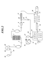
- FIG. 2 is a diagram schematically showing an example of a dope preparation step, a casting step, and a drying step of a solution casting film forming method preferable for the present invention.
- additives are prepared or prepared in the charging tank 41, then sent from the charging tank 41 to the filter 44 by the pump 43, large aggregates are removed by the filter 44, and then sent to the additive stock tank 42. Liquid. Thereafter, various additive solutions are added to the main dope dissolving vessel 1 from the stock vessel 42 of each additive.
- the main dope is sent to the main filter 3 by the pump 2 and filtered, and an ultraviolet absorbent additive prepared in a separate line is added in-line through the conduit 16 to the main dope.
- an ultraviolet absorbent additive prepared in a separate line is added in-line through the conduit 16 to the main dope.
- the detailed description of the preparation process of a ultraviolet absorber addition liquid is abbreviate
- the main dope may contain a recycled material in the range of 10 to 50% by mass.
- Recycled material is a finely pulverized piece of cellulose ester film, which exceeds the specified value of the film due to film edges that are cut off on both sides of the film or scratches that occur when the cellulose ester film is formed.
- a cellulose ester film is used.
- a pellet obtained by pelletizing cellulose ester (cellulose acetate) and other compounds in advance can be preferably used as a raw material of the resin used for preparing the dope.
- An endless metal belt such as a stainless steel belt or a rotating metal drum, which feeds the dope to a pressure die 30 through a liquid feed pump (for example, a pressurized metering gear pump) and transfers it indefinitely.
- the dope is cast from the slit of the pressure die 30 to the casting position on the metal support 31.
- ⁇ Slit shape of die die can be adjusted, and a pressure die that facilitates uniform film thickness is preferred.
- the pressure die include a coat hanger die and a T die, and any of them is preferably used.
- the surface of the metal support is a mirror surface.
- two or more pressure dies 30 may be provided on the metal support 31 and the dope amount may be divided and laminated. Or it is also a preferable film-forming method to obtain the film of a laminated structure by the co-casting method which casts several dope simultaneously.
- Solvent evaporation step A web (hereinafter, a dope is cast on a casting support and the formed dope film is referred to as a web) is heated on the casting metal support 31 to evaporate the solvent. It is a process.
- the web on the metal support 31 after casting is preferably dried on the support in an atmosphere of 40 to 100 ° C. In order to maintain the atmosphere at 40 to 100 ° C., it is preferable to apply hot air at this temperature to the upper surface of the web or heat by means such as infrared rays.
- the web is preferably peeled from the metal support 31 within 30 to 120 seconds.
- the temperature at the peeling position 33 on the metal support 31 is preferably in the range of 10 to 40 ° C., more preferably in the range of 11 to 30 ° C.
- the residual solvent amount at the time of peeling of the web on the metal support 31 at the time of peeling is peeled within a range of 50 to 120% by mass depending on the strength of drying conditions, the length of the metal support 31 and the like.
- the residual solvent amount at the time of peeling is set.
- the amount of residual solvent in the web is defined by the following formula (4).
- Residual solvent amount (%) (mass before web heat treatment ⁇ mass after web heat treatment) / (mass after web heat treatment) ⁇ 100 Note that the heat treatment for measuring the residual solvent amount represents performing heat treatment at 115 ° C. for 1 hour.
- the peeling tension at the time of peeling the metal support 31 from the film is usually in the range of 196 to 245 N / m. However, if wrinkles easily occur at the time of peeling, the film can be peeled with a tension of 190 N / m or less. preferable.
- the temperature at the peeling position 33 on the metal support 31 is preferably in the range of ⁇ 50 to 40 ° C., more preferably in the range of 10 to 40 ° C., and in the range of 15 to 30 ° C. Is most preferable.
- the drying means is generally to blow hot air on both sides of the web, but there is also a means to heat by applying microwaves instead of wind. Too rapid drying tends to impair the flatness of the finished film. Drying at a high temperature is preferably performed from about 8% by mass or less of the residual solvent. Throughout, the drying is generally carried out in the range of 40-250 ° C. It is particularly preferable to dry within the range of 40 to 200 ° C.
- tenter stretching device 34 When using the tenter stretching device 34 in the stretching process, it is preferable to use a device that can independently control the film gripping length (distance from the start of gripping to the end of gripping) left and right by the left and right gripping means of the tenter. In the tenter process, it is also preferable to intentionally create sections having different temperatures in order to improve planarity.
- the stretching operation in the stretching step may be performed in multiple stages, and it is particularly preferable to perform biaxial stretching in the casting direction and the width direction.
- biaxial stretching When biaxial stretching is performed, simultaneous biaxial stretching may be performed or may be performed stepwise.
- the draw ratio is 1.05 to 2.5 times, preferably 1.1 to 1.5 times the original width of the film, by adding the casting direction and the width direction. preferable. More preferably, it is in the range of 1.1 to 1.4 times.
- stepwise means that, for example, stretching in different stretching directions can be sequentially performed, stretching in the same direction is divided into multiple stages, and stretching in different directions is added to any one of the stages. Is also possible. That is, for example, the following stretching steps are possible.
- the cellulose ester film according to the present invention it is preferable from the viewpoint of obtaining a desired Martens hardness, after drying, to perform a stretching treatment under the condition that the amount of residual solvent in the film is 0.5 to 4.0% by mass. .
- the temperature distribution in the width direction of the atmosphere is small from the viewpoint of improving the uniformity of the film, and the temperature distribution in the width direction in the tenter stretching step is preferably within ⁇ 5 ° C., and ⁇ 2 It is more preferably within 1 ° C, and most preferably within 1 ° C.
- the cellulose ester film according to the present invention is a thin film having a film thickness in the range of 15 to 40 ⁇ m, when the cellulose ester film is stored in a roll shape, Although there is a concern about deviation and deterioration of optical quality (film surface homogeneity), they can be effectively prevented by embossing to give embossed portions to both ends of the cellulose ester film.
- the embossed part is a constant consisting of minute concavities and convexities at the end of the film in order to prevent the back surface and the surface of the wound film from completely contacting each other before winding the long film. It has a pattern with a width of.
- a relatively concave shape is formed on the other surface (for example, the lower surface) of the film corresponding to the convex shape.
- the cellulose ester film according to the present invention has a high Martens hardness within the range of 140 to 230 N / mm 2 , and the embossing to be formed becomes hard, so that the wound films are completely bonded or partially
- the embossing effect can prevent the film from adhering to the film and affecting the surface condition of the film and causing failure.
- an embossed portion having a height in the range of 1 to 20 ⁇ m is formed in a region within 5% of the film width from both ends in the film width direction, After holding for 10 minutes with a 1 kg load applied to a 5 mm diameter circular region on the surface of the embossed part under% RH, the height of the convex part of the embossed part is set to D and the load is applied.
- the embossing crush resistance (%) defined by the following formula (1) is preferably 50% or more for both embossed portions.
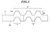
- FIG. 3 is a cross-sectional view showing an example of the structure in the vicinity of the embossed portion of the cellulose ester film 102.
- the height D 0 of the plurality of convex portions 51A constituting the embossed portion 51 is preferably in the range of 1 to 20 ⁇ m, and more preferably in the range of 2 to 15 ⁇ m.
- the height D 0 of the convex portion 51A refers to the height from the film surface F (the film surface of the base portion where no embossing is formed) to the apex of the convex portion 51A.
- convex part 51A If the height of convex part 51A is 1 micrometer or more, it will become difficult to adhere cellulose ester films closely, and is preferable. On the other hand, if the height of the convex portion 51A is 20 ⁇ m or less, there is no deflection in the widthwise central portion where the roll laminate is not embossed, and the flatness as the cellulose ester film can be maintained. it can.
- the convex part 51A which is an embossed part when the film width length of the cellulose ester film 102 is 100%, is formed in a region within 5% from each end part to sufficiently secure the effective area of the cellulose ester film. From the viewpoint of being able to do so.
- the width w of the convex portion 51A is preferably in the range of 0.05 to 5 mm.
- the width w of the convex portion 51 ⁇ / b> A is expressed as a distance between two points in the convex portion 51 ⁇ / b> A where the convex portion 51 ⁇ / b> A intersects the film surface F in the cross section of the embossed portion 51.
- the distance b between the convex portion 51A and the convex portion 51A is preferably in the range of 0.1 to 5 mm, and more preferably in the range of 0.5 to 2 mm.
- the interval b between the convex portions 51 ⁇ / b> A and the convex portions 51 ⁇ / b> A is represented by the distance between the convex portions 51 ⁇ / b> A where two adjacent convex portions 51 ⁇ / b> A intersect the film surface F in the cross section of the embossed portion 51.
- the width w of the embossed portion 51 is preferably in the range of 0.12 to 2.1% with respect to the width of the cellulose ester film 102. Specifically, although the width w of the embossed portion 51 depends on the width of the cellulose ester film 102, it is not in the range of 5 to 25 mm and is preferably in the range of 10 to 20 mm. If the width w of the embossed part 51 is within the above range, it is easy to secure an area that can be used as a cellulose ester film, and adhesion between the front and back surfaces of the cellulose ester film can be prevented.
- the cellulose ester film according to the present invention is such that even if force is applied to the embossed portion 51 of the cellulose ester film 102, the convex portion 51A of the embossed portion is not easily crushed, that is, the embossed portion 51 has a high Martens hardness. It has characteristics that can suppress the deterioration of the winding shape when laminated in a roll shape.
- the average value of the embossing crushing resistance (%) of the convex portion 51A of the embossed part measured by the following method is preferably 50% or more at the left and right ends of the film, and 70% or more. More preferably.
- the embossing crush resistance (%) of the convex portion 51A of the embossed portion can be measured by the following method.
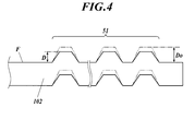
- FIG. 4 is a partial cross-sectional view showing an example of the embossed part 51 in the measurement of the embossing crushing rate
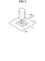
- FIG. 5 is a schematic perspective view showing an example of a method for measuring the embossing crushing rate of the convex part 51A of the embossed part. is there.
- a region including the embossed portion 51 of the cellulose ester film 102 is cut out to obtain a sample film 50A (see FIG. 5). Then, the convex portion 51A of the embossed portion 51 of the sample film 50A (in FIG. 4, the height D 0 of the front convex portion 51A which applies a load) Height D 0 and measured at a thickness measuring instrument.
- a thickness measuring device for example, a constant pressure thickness measuring device (PG-02 manufactured by Teclock Co., Ltd.) can be used.
- the sample film 50 ⁇ / b> A is placed on the stage 52.
- a weight 53 of a total of 1 kg consisting of a metal cylindrical rod 53A having a diameter of 5 mm placed perpendicular to the film surface and a weight 53B placed thereon is placed.
- this state is maintained for 10 minutes in an environment of 23 ° C. and 55% RH with a load of 1 kg applied to a circular region having a diameter of 5 mm on the surface of the embossed portion 51.
- the height D of the convex portion 51A of the embossed portion 51 after removing the load (excluding the weight) is measured with a thickness measuring machine. taking measurement.
- the adjustment of the embossing crushing rate (%) of the convex portion of the embossed portion is not particularly limited and various methods can be adopted, but a cellulose ester film having the characteristics according to the present invention is applied. In addition, it is preferable to carry out under the embossing conditions shown below.
- the surface temperature of the embossing roller, (2) the surface temperature of the back roller, (3) the roller diameter of the embossing roller, and (4) the combination of two or more of the materials of the back roller. can do.
- Winding step This is a step of winding up the cellulose ester film by the winder 37 shown in FIG. 2 after the residual solvent amount in the web is 2% by mass or less. Thus, a film having good dimensional stability can be obtained. In particular, it is preferable to wind in a range of 0.00 to 0.10% by mass.
- a generally used method may be used, and there are a constant torque method, a constant tension method, a taper tension method, a program tension control method with a constant internal stress, and the like.
- the cellulose ester film according to the present invention is preferably a long film, specifically, preferably a winding length in the range of 100 to 10,000 m, particularly preferably a cellulose ester having a winding length of 5000 m or more. It is a roll laminated body of a film.
- the film width is preferably 1 to 4 m, more preferably 1.4 to 3 m.
- the thickness of the cellulose ester film according to the present invention is in the range of 15 to 40 ⁇ m, and preferably in the range of 15 to 30 ⁇ m.
- the cellulose ester film laminate produced by the above method can be subjected to an aging treatment for 3 days or more under conditions of 50 ° C or higher after the outer peripheral portion is packaged. This is a preferable manufacturing condition from the viewpoint that the coefficient of variation of Martens hardness can be set to a desired condition.
- the roll laminate of the cellulose ester film according to the present invention is a resin film for packaging, in particular, after the outer peripheral portion is packaged with a moisture-proof film vapor-deposited on the resin film for packaging, and then the winding shaft portion is fastened with a string or rubber band A storage form is preferred.
- FIG. 6 an example of the packaging form of the roll laminated body of the cellulose-ester film which is the protective film A which concerns on this invention is shown in a schematic diagram.
- the packaging form 210 of the roll laminated body of the cellulose-ester film which is the protective film A which concerns on this invention shown in FIG. 6 the surrounding surface of the cellulose-ester film wound up by the cylindrical core 201 in roll shape The entire left and right side surfaces are covered with a sheet-like packaging material 203, and both end portions of the packaging material 203 in the roll circumferential direction are overlapped with each other.
- the left and right ends are fastened with multiple layers of gummed tape, and the winding shaft portion is fastened with a string or rubber band rather than having a gap substantially without sealing inside,
- the roll body can be appropriately absorbed and dehumidified during storage or transportation, which is a preferred embodiment for enhancing the uniformity of the optical properties and physical properties of the optical film.
- Examples of the packaging material 203 constituting the packaging form of the roll laminate include a film of a polyolefin-based synthetic resin such as polyethylene or polypropylene, and a film of a polyester-based synthetic resin such as polyethylene terephthalate and polyethylene naphthalate.
- the thickness of the packaging material 203 is preferably 10 ⁇ m or more from the viewpoint of maintaining moisture resistance, and is preferably 100 ⁇ m or less from the viewpoint of handling such as rigidity.
- the moisture resistance of the packaging material 203 varies depending on the thickness of the synthetic resin film constituting the packaging material 203, the moisture resistance of the packaging material 203 can be appropriately adjusted by adjusting the thickness of the synthetic resin film. Can do.
- the moisture resistance of the packaging material 203 if the moisture permeability per day specified by JIS Z0208 is 10 g / m 2 or less, the desired Martens hardness and the coefficient of variation of the Martens hardness in the width direction are This is preferable because it can be realized and, in addition, deterioration of the winding shape and foreign matter failure can be prevented, and the occurrence of scratches caused thereby is less likely to occur.
- the moisture vapor transmission rate per day prescribed by JIS Z 0208 is 5 g / m 2 or less for the roll laminated body of the cellulose ester film.
- Packaging with the packaging material 203 is preferable, and packaging with the packaging material 203 having a moisture permeability of 1 g / m 2 or less is more preferable. The reason is that deterioration during storage (deterioration of the winding shape, occurrence of sticking failure between films and foreign matter failure) in a physical distribution state such as storage and transportation of the film can be further suppressed.
- packaging material 203 for example, a polyolefin-based synthetic resin films such as polyethylene and polypropylene, Composite materials laminated with polyester-based synthetic resin films such as polyethylene terephthalate and polyethylene naphthalate, or a metal such as aluminum is deposited on these films, or a thin film of metal is laminated and laminated. And composite materials.
- the thickness of the packaging material 203 made of these composite materials is preferably 1 ⁇ m or more from the viewpoint of maintaining moisture resistance, and is preferably 50 ⁇ m or less from the viewpoint of handling such as rigidity. Since the moisture resistance of the packaging material 203 changes depending on the thickness of the composite material, the moisture resistance of the packaging material 203 can be appropriately adjusted by adjusting the thickness.
- a composite material in which a polyolefin-based synthetic resin film such as polyethylene and polypropylene and a polyester-based synthetic resin film such as polyethylene terephthalate and polyethylene naphthalate are laminated, and a metal foil such as aluminum is deposited on these films.
- a composite material in which a metal thin film is bonded to form a laminated body can be used particularly preferably in terms of handling because high moisture resistance is obtained and the material is lightweight.
- the packaging material 203 having the above-described form can exhibit the above-described effect by winding at least once on the roll laminate of the cellulose ester film according to the present invention, but preferably wound twice or more.
- the roll laminate of the cellulose ester film according to the present invention packaged in the above packaging form is a cellulose ester film having a uniform Martens hardness without deterioration of the winding shape even during long-term storage in a warehouse or transportation by truck or ship. Can be provided.
- the polarizer which is the main component of the polarizing plate of the present invention, is an element that passes only light having a plane of polarization in a certain direction, and a typical known polarizer is a polyvinyl alcohol polarizing film.
- the polyvinyl alcohol polarizing film includes those obtained by dyeing iodine on a polyvinyl alcohol film and those obtained by dyeing a dichroic dye.
- polarizer a polarizer obtained by forming a polyvinyl alcohol aqueous solution into a film and dyeing it by uniaxial stretching or dyeing and then uniaxially stretching and then preferably performing a durability treatment with a boron compound may be used.
- the thickness of the polarizer is generally in the range of 2 to 30 ⁇ m, but in the present invention, it is preferably in the range of 2 to 15 ⁇ m.
- the average ethylene unit content described in JP-A-2003-248123, JP-A-2003-342322, etc. is 1 to 4 mol%
- the degree of polymerization is 2000 to 4000
- the degree of saponification is 99.0 to 99.99 mol. %
- Ethylene-modified polyvinyl alcohol is also preferably used.
- an ethylene-modified polyvinyl alcohol film having a hot water cutting temperature in the range of 66 to 73 ° C. is preferably used.
- a polarizer using this ethylene-modified polyvinyl alcohol film is excellent in polarization performance and durability performance, has few color spots, and can be particularly preferably applied to a large liquid crystal display device.
- a coating type polarizer is produced by the method described in JP 2011-1000016 A, JP 4691205 A, JP 4751481, JP 4804589 A, etc., and the protective film A according to the present invention is used. It is also preferable to produce a polarizing plate by laminating with a certain cellulose ester film.
- one of the characteristics is that the cellulose ester film, which is the protective film A described above, and at least one surface of the polarizer are bonded with an ultraviolet curable adhesive.
- a retardation film which is a protective film B described later, and a polarizer are similarly bonded by an ultraviolet curable adhesive.
- the productivity is high and the durability of the polarizer is increased. Excellent properties can be obtained.
- composition of UV curable adhesive examples include a photo radical polymerization composition using photo radical polymerization, a photo cation polymerization composition using photo cation polymerization, and photo radical polymerization and photo cation polymerization. Hybrid type compositions using a combination of these are known.
- the photo-radical polymerization composition examples include a specific ratio of a radical polymerizable compound containing a polar group such as a hydroxy group and a carboxy group described in JP-A-2008-009329 and a radical polymerizable compound not containing a polar group. And the like are known.
- the radical polymerizable compound is preferably a compound having a radical polymerizable ethylenically unsaturated bond.
- the compound having an ethylenically unsaturated bond capable of radical polymerization include a compound having a (meth) acryloyl group.
- the compound having a (meth) acryloyl group examples include an N-substituted (meth) acrylamide compound and a (meth) acrylate compound.
- (Meth) acrylamide means acrylamide or methacrylamide.
- cationic photopolymerization type composition as described in JP 2011-028234 A, ( ⁇ ) cationic polymerizable compound, ( ⁇ ) photo cationic polymerization initiator, ( ⁇ ) wavelength longer than 380 nm UV curable adhesive compositions composed of components such as a photosensitizer exhibiting maximum absorption of light and ( ⁇ ) a naphthalene photosensitizer.
- ⁇ cationic photopolymerization type composition
- ⁇ cationic photopolymerization type composition, as described in JP 2011-028234 A, ( ⁇ ) cationic polymerizable compound, ( ⁇ ) photo cationic polymerization initiator, ( ⁇ ) wavelength longer than 380 nm UV curable adhesive compositions composed of components such as a photosensitizer exhibiting maximum absorption of light and ( ⁇ ) a naphthalene photosensitizer.
- other ultraviolet curable adhesives may be used.
- a pre-processing process is a process of performing an easily bonding process with respect to the adhesive surface with the polarizer of a cellulose-ester film.
- an easy adhesion treatment is performed on the surface side of each protective film to be bonded to the polarizer. Examples of the easy adhesion treatment include corona treatment and plasma treatment.
- the ultraviolet curable adhesive is applied to at least one of the adhesive surfaces of the polarizer and the protective film A.
- the application method is not particularly limited. For example, a doctor blade, a wire bar, a die coater, a comma coater, a gravure coater, etc. Various wet coating methods can be used.
- the method of pressurizing with a roll etc. and spreading it uniformly can also be utilized.
- Bonding process After apply
- this bonding step for example, when an ultraviolet curable adhesive is applied to the surface of the polarizer in the previous application step, the protective film A is superimposed there.
- a polarizer is superimposed thereon.
- the protective film A and the protective film B are bonded to both surfaces of the polarizer
- the protective film A and the protective film B are respectively bonded to both surfaces of the polarizer via an ultraviolet curable adhesive.
- an ultraviolet curable adhesive Are applied in a state of being superposed, and a method of simultaneously curing the ultraviolet curable adhesive on both sides is advantageous.
- the dose of ultraviolet rays is preferably in accumulated light amount is within the range of 50 ⁇ 1500mJ / cm 2, even more preferably in the range of 100 ⁇ 500mJ / cm 2.
- the polarizing plate of this invention has the protective film B with the protective film A and a polarizer, It is characterized by the above-mentioned.
- the resin material that can be used for the production of the retardation film according to the present invention is not particularly limited, but may be a cellulose resin (for example, a cellulose ester film (such as the protective film A (cellulose acetate) according to the present invention), acrylic, etc.
- the resin include a polycarbonate resin, a polycarbonate resin, and a cycloolefin polymer. Among these, a film composed of a cycloolefin polymer is preferable.
- ⁇ Cellulosic resin examples include cellulose acetate propionate, cellulose acetate butyrate, cellulose acetate propionate butyrate or cellulose acetate phthalate as well as propionate group, butyrate group or phthalyl group.
- a mixed fatty acid ester of cellulose to which is bound can be used.
- the butyryl group that forms butyrate may be linear or branched.
- Examples of the cellulose ester used in the present invention include cellulose acetate, cellulose acetate butyrate, and cellulose acetate propionate.
- the cellulose acetate preferably has an average degree of acetyl group substitution of 2.00 or more, more preferably in the range of 2.00 to 2.95, and further in the range of 2.20 to 2.90. preferable.
- the protective film B composed of a cellulose-based resin can be obtained as a commercially available product.
- a commercially available cellulose ester film for example, Konica Minoltack KC8UX, KC5UX, KC4UX, KC8UCR3, KC4SR, KC4BR, KC4CR, KC4DR KC4FR, KC4KR, KC8UY, KC6UY, KC4UY, KC4UE, KC8UE, KC8UY-HA, KC2UA, KC4UA, KC6UA, KC2UAH, KC4UAH, KC6UAH, and more
- polycarbonate resin examples include aromatic polycarbonates obtained by a reaction between an aromatic dihydric phenol and a carbonate precursor.
- the aromatic polycarbonate used in the present invention is not particularly limited as long as it is an aromatic polycarbonate capable of obtaining desired properties of the film.
- a polymer material called polycarbonate uses a polycondensation reaction as a synthesis method thereof, and is a general term for a material in which the main chain is linked by a carbonic acid bond.
- a phenol derivative and a phosgene are generally used.
- an aromatic polycarbonate represented by a repeating unit having 2,2-bis (4-hydroxyphenyl) propane called bisphenol-A as a bisphenol component is preferably selected.
- bisphenol derivatives should be selected as appropriate.
- an aromatic polycarbonate copolymer can be constituted.
- Examples of the copolymer component constituting the polycarbonate-based resin include bis (4-hydroxyphenyl) methane, 1,1-bis (4-hydroxyphenyl) cyclohexane, 9,9 in addition to bisphenol-A described above.
- -B is (4-hydroxyphenyl) fluorene, 1,1-bis (4-hydroxyphenyl) -3,3,5-trimethylcyclohexane, 2,2-bis (4-hydroxy-3-methylphenyl) propane, 2, 2-bis (4-hydroxyphenyl) -2-phenylethane, 2,2-bis (4-hydroxyphenyl) -1,1,1,3,3,3-hexafluoropropane, bis (4-hydroxyphenyl) Diphenylmethane, bis (4-hydroxyphenyl) sulfide, bis (4-hydroxyphenyl) sulfone, 1,1 Bis (4-hydroxyphenyl) -3,3,5-trimethylcyclohexane, and the like.
- the polycarbonate-based resin can also be selected and used as appropriate.
- the retardation film (protective film B) according to the present invention it is particularly preferable to use a film composed of a cycloolefin polymer.
- the cycloolefin polymer applicable to the present invention is composed of a polymer resin containing an alicyclic structure.
- a preferred cycloolefin polymer is a resin obtained by polymerizing or copolymerizing a cyclic olefin.
- cyclic olefin examples include norbornene, dicyclopentadiene, tetracyclododecene, ethyltetracyclododecene, ethylidenetetracyclododecene, tetracyclo [7.4.0.110, 13.02,7] trideca-2, Polycyclic unsaturated hydrocarbons such as 4,6,11-tetraene and derivatives thereof; cyclobutene, cyclopentene, cyclohexene, 3,4-dimethylcyclopentene, 3-methylcyclohexene, 2- (2-methylbutyl) -1-cyclohexene Monocyclic unsaturated hydrocarbons such as cyclooctene, 3a, 5,6,7a-tetrahydro-4,7-methano-1H-indene, cycloheptene, cyclopentadiene, cyclohexadiene, and derivatives thereof.
- cyclic olefins may have a polar group as a substituent.
- the polar group include a hydroxy group, a carboxy group, an alkoxyl group, an epoxy group, a glycidyl group, an oxycarbonyl group, a carbonyl group, an amino group, an ester group, and a carboxylic acid anhydride group.
- a carboxy group or a carboxylic anhydride group is preferred.
- Preferred cycloolefin polymers may be those obtained by addition copolymerization of monomers other than cyclic olefins.
- the addition copolymerizable monomer include ethylene or ⁇ -olefin such as ethylene, propylene, 1-butene and 1-pentene; 1,4-hexadiene, 4-methyl-1,4-hexadiene, 5- And dienes such as methyl-1,4-hexadiene and 1,7-octadiene.
- the cyclic olefin can be obtained by an addition polymerization reaction or a metathesis ring-opening polymerization reaction.
- the polymerization reaction is usually performed in the presence of a catalyst.
- addition polymerization catalyst examples include a polymerization catalyst composed of a vanadium compound and an organoaluminum compound.
- a polymerization catalyst comprising a metal halide such as ruthenium, rhodium, palladium, osmium, iridium, platinum, nitrate or acetylacetone compound, and a reducing agent, or titanium, vanadium, zirconium,
- metal halide such as ruthenium, rhodium, palladium, osmium, iridium, platinum, nitrate or acetylacetone compound
- a reducing agent or titanium, vanadium, zirconium
- titanium, vanadium, zirconium examples thereof include polymerization catalysts composed of metal halides such as tungsten and molybdenum or acetylacetone compounds and organoaluminum compounds.
- Conditions such as polymerization temperature and pressure are not particularly limited, but the polymerization is usually carried out at a polymerization temperature of -50 to 100 ° C. and a pressure range of 0 to 490 N / cm 2 .
- cycloolefin polymer it is preferable to apply a method in which a cyclic olefin is polymerized or copolymerized and then hydrogenated to convert unsaturated bonds in the molecule into saturated bonds.
- the hydrogenation reaction is performed by blowing hydrogen gas in the presence of a known hydrogenation catalyst.
- the hydrogenation catalyst examples include transition metals such as cobalt acetate / triethylaluminum, nickel acetylacetonate / triisobutylaluminum, titanocene dichloride / n-butyllithium, zirconocene dichloride / sec-butyllithium, tetrabutoxytitanate / dimethylmagnesium.
- transition metals such as cobalt acetate / triethylaluminum, nickel acetylacetonate / triisobutylaluminum, titanocene dichloride / n-butyllithium, zirconocene dichloride / sec-butyllithium, tetrabutoxytitanate / dimethylmagnesium.
- Homogeneous catalyst comprising a combination of compound / alkyl metal compound; heterogeneous metal catalyst such as nickel, palladium, platinum, etc .; nickel / silica, nickel / diatomaceous earth, nickel / alumina, palladium / carbon, palladium / silica, palladium / Examples thereof include heterogeneous solid supported catalysts obtained by supporting a metal catalyst such as diatomaceous earth and palladium / alumina on a support.
- the cycloolefin polymer the following norbornene-based resins can also be mentioned.
- the norbornene-based resin preferably has a norbornene skeleton as a repeating unit. Specific examples thereof include, for example, JP-A-62-252406, JP-A-62-2252407, and JP-A-2-133413. JP, 63-145324, JP 63-264626, JP 1-2240517, JP 57-8815, JP 5-2108, JP 5-39403.
- the cycloolefin polymer can also be obtained as a commercial product. Specifically, ZEONEX manufactured by Nippon Zeon Co., Ltd., ZEONOR (trade name), Arton (trade name) manufactured by JSR Corporation, Appell (trade name, APL8008T, APL6509T, APL6013T, APL5014DP, APL6015T) manufactured by Mitsui Chemicals, Inc. is preferably used.
- the molecular weight of the cycloolefin polymer is appropriately selected according to the purpose of use, but is converted to polyisoprene or polystyrene measured by gel permeation chromatography method of cyclohexane solution (or toluene solution if the polymer resin does not dissolve).
- the mechanical strength of the molded article is usually within the range of 5000 to 500,000, preferably within the range of 8000 to 200,000, more preferably within the range of 10,000 to 100,000. Molding processability is highly balanced and suitable.
- the conventional surface cannot be bonded with water glue (polyvinyl alcohol adhesive) after saponification, so the polarizer and the protective film B (position) It is effective to apply a method of laminating a phase difference film) using an ultraviolet curable adhesive.
- the polarizing plate provided with the protective film A which is a cellulose ester film according to the present invention, can be used in various display devices, but is particularly preferably applied to a liquid crystal display device.
- liquid crystal display device including the polarizing plate of the present invention
- a TN (Twisted Nematic) method a STN (Super Twisted Nematic) method
- an IPS (In-Plane Switching) method an OCB (Optically Compensated Birefringce) method.
- It can be preferably used for a Vertical Alignment (MVA) system (including a multi-domain Vertical Alignment and PVA; Patterned Vertical Alignment), a HAN (Hybrid Aligned Nematic) system, and the like.
- the VA (MVA, PVA) method is preferable.
- the polarizing plate of the present invention uses an obliquely stretched ⁇ / 4 retardation film as the retardation film that is the protective film B together with the protective film A (cellulose ester film) according to the present invention, and displays organic electroluminescence. It is also preferably used as a polarizing plate for organic electroluminescence applied to the apparatus.
- the configuration of the organic EL display device is shown below, but is not limited thereto.
- a protective film according to the present invention is applied to a polarizer on an organic EL device having a metal electrode, a TFT, an organic light emitting layer, a transparent electrode (ITO, etc.), an insulating layer, and a sealing layer in this order on a substrate using glass or polyimide.
- a and the polarizing plate (circular polarizing plate) of this invention comprised by A and the protective film B are provided, and an organic electroluminescent image display apparatus is comprised. In this case, it is necessary to arrange the protective film B ( ⁇ / 4 retardation film) on the organic EL element side.
- the organic light emitting layer is a laminate of various organic thin films, for example, a laminate of a hole injection layer made of a triphenylamine derivative or the like and a light emitting layer made of a fluorescent organic solid such as anthracene, Or a structure having various combinations such as a laminate of such a light-emitting layer and an electron injection layer made of a perylene derivative, or a laminate of these hole injection layer, light-emitting layer, and electron injection layer.
- a laminate of various organic thin films for example, a laminate of a hole injection layer made of a triphenylamine derivative or the like and a light emitting layer made of a fluorescent organic solid such as anthracene, Or a structure having various combinations such as a laminate of such a light-emitting layer and an electron injection layer made of a perylene derivative, or a laminate of these hole injection layer, light-emitting layer, and electron injection layer.
- an organic EL image display device by applying a voltage between a transparent electrode and a metal electrode, holes and electrons are injected into the organic light-emitting layer, and energy generated by recombination of these holes and electrons is converted into a phosphor material. It emits light on the principle that it is excited and emits light when the excited fluorescent material returns to the ground state.
- the mechanism of recombination in the middle is the same as that of a general diode, and as can be predicted from this, the current and the emission intensity show strong nonlinearity with rectification with respect to the applied voltage.
- At least one of the electrodes needs to be transparent, and is usually formed of a transparent conductor such as indium tin oxide (ITO).
- ITO indium tin oxide
- the electrode is preferably used as the anode.
- metal electrodes such as Mg—Ag and Al—Li are used.
- the organic light emitting layer is formed of a very thin film having a thickness of about 10 nm. For this reason, the organic light emitting layer transmits light almost completely like the transparent electrode. As a result, light that is incident from the surface of the transparent substrate at the time of non-light emission, passes through the transparent electrode and the organic light emitting layer, and is reflected by the metal electrode is again emitted to the surface side of the transparent substrate.
- the display surface of the organic EL image display device looks like a mirror surface.
- an organic EL image display device including an organic EL element having a transparent electrode on the surface side of an organic light emitting layer that emits light by applying a voltage and a metal electrode on the back side of the organic light emitting layer, the surface side of the transparent electrode ( By providing a circularly polarizing plate on the viewing side), light passing through it is transmitted through the transparent substrate, transparent electrode, and organic thin film, reflected by the metal electrode, and again transmitted through the organic thin film, transparent electrode, and transparent substrate. Then, since the circularly polarizing plate makes the linearly polarized light again, this linearly polarized light is orthogonal to the polarization direction of the polarizing plate, and cannot pass through the polarizing plate. As a result, the mirror surface of the metal electrode can be completely shielded.
- the polarizing plate of the present invention is a polarizing plate for organic electroluminescence that is applied to an organic electroluminescence display device using an obliquely stretched ⁇ / 4 retardation film as a retardation film together with the cellulose ester film according to the present invention. Also, it is preferably used.
- Example 1 Production of cellulose acetate film >> [Production of Cellulose Acetate Film 1] (Preparation of fine particle dispersion) 10 parts by mass of Aerosil 972V (manufactured by Nippon Aerosil Co., Ltd., primary average particle size: 16 nm, apparent specific gravity 90 g / L) and 90 parts by mass of ethanol were mixed with stirring for 30 minutes with a dissolver, and then high pressure A fine particle dispersion was prepared by dispersing using a Manton Gorin type homogenizer which is a type disperser.
- Aerosil 972V manufactured by Nippon Aerosil Co., Ltd., primary average particle size: 16 nm, apparent specific gravity 90 g / L
- a fine particle dispersion was prepared by dispersing using a Manton Gorin type homogenizer which is a type disperser.
- the obtained dope 1 was uniformly cast on a stainless steel band support using a belt casting apparatus under the conditions of a liquid temperature of the dope 1 of 35 ° C. and a width of 1.95 m.
- the organic solvent in the obtained dope film was evaporated until the residual solvent amount reached 100% by mass to form a web, and then the web was peeled from the stainless steel band support.
- the obtained web was further dried at 35 ° C. and then slit to have a width of 1.90 m. Thereafter, the web was stretched 1.2 times in the TD direction (the width direction of the film) with a tenter under the condition of 160 ° C.
- the residual solvent amount of the web at the start of stretching was 2.0% by mass.
- the draw ratio of MD direction computed from the rotational speed of a stainless steel band support body and the driving speed of a tenter was 1.0. Thereafter, the obtained film was dried at 120 ° C. for 15 minutes while being transported by a number of rolls in the drying apparatus, then slit to 2.2 m width, and the height of the convex portion was 10 ⁇ m at both ends in the width direction.
- the embossed part (the width w of the embossed part: 15 mm) having a width w of the convex part of 100 ⁇ m and an interval between the convex parts of 1000 ⁇ m was formed. Embossing was performed under the following conditions.
- the outer periphery of the laminated roll body 1 is double-wrapped using a moisture-proof film packaging material in which aluminum is vapor-deposited on a 50 ⁇ m thick polyethylene resin film, and the end of the core is fastened with a rubber band. Was made.
- the produced laminated roll body 1A was subjected to an aging treatment for 3 days in a constant temperature environment of 50 ° C. to produce a cellulose acetate film 1.
- Martens hardness was obtained by measuring under the following measurement conditions using a dynamic ultra-micro hardness meter DUH-211S (manufactured by Shimadzu Corporation).
- Indenter shape Triangular pyramid indenter (edge angle 115 °) Measurement environment: temperature 23 ° C, relative humidity 50% Maximum test load: 196.13mN Loading speed: 6.662 mN / 10 seconds Maximum load creep time: 10 seconds Unloading speed: 6.662 mN / 10 seconds [Measurement of coefficient of variation of Martens hardness] Using the measured values of the Martens hardness (N / mm 2 ) at 50 locations in the width direction, the coefficient of variation of the Martens hardness in the width direction was calculated according to the following formula.
- Variation coefficient of Martens hardness (%) (standard deviation of Martens hardness / average value of Martens hardness) ⁇ 100 [Measurement of embossing crush resistance] According to the method shown in FIGS. 4 and 5, the embossing crush resistance (%) of the convex portion of the embossed portion was measured. The measurement procedure is as follows.
- a region including the embossed portion 51 of the cellulose acetate film 102 was cut out to produce a sample film 50A (see FIG. 5). Then, the convex portion of the embossed portion 51 of the sample film 50A (in FIG. 4, the height D 0 of the convex portion before applying a load) Height D 0 was measured by a thickness measuring instrument.
- a thickness measuring instrument a constant pressure thickness measuring device (TECLOCK PG-02 Co., Ltd.) was used.
- Embossing crush resistance (%) D / D 0 ⁇ 100 (%) The measurement was made at 10 arbitrary positions of the embossed portion, and the average value of the embossing crush resistance (%) was obtained.
- Table 1 shows the measurement results obtained as described above.
- UV curable adhesive 1 After mixing the following components, defoaming was performed to prepare an ultraviolet curable adhesive 1. Triarylsulfonium hexafluorophosphate was blended as a 50% propylene carbonate solution, and the solid content of triarylsulfonium hexafluorophosphate was shown below. In Table 2, UV adhesive 1 was abbreviated.
- the retardation values Ro and Rt of the protective film B1 were measured according to the following method.
- the retardation value was measured according to the following formula using an automatic birefringence meter KOBRA-WPR (Oji Scientific Instruments).
- n x represents a refractive index in the direction x in which the refractive index in the plane direction is maximized in the film.
- n y in-plane direction of the film, the refractive index in the direction y perpendicular to the direction x.
- nz represents the refractive index in the thickness direction z of the film.
- d represents the thickness (nm) of the film.
- protective film B2 cellulose acetate propionate film
- B2 CAP in the column of the protective film B in Table 2
- Fine particles (Aerosil R972V manufactured by Nippon Aerosil Co., Ltd.) 11 parts by mass Ethanol 89 parts by mass The above was stirred and mixed with a dissolver for 50 minutes, and then dispersed with a Manton Gorin type homogenizer which is a high-pressure disperser.
- a dope B2 having the following composition was prepared. First, methylene chloride and ethanol were added to the pressure dissolution tank. Cellulose acetate propionate (average acetyl group substitution degree: 1.56, propionyl group substitution degree: 0.90, Mw: 180000) was added to the pressure dissolution tank containing the organic solvent with stirring. This was completely dissolved while being heated and stirred, and this was dissolved in Azumi filter paper No. 1 manufactured by Azumi Filter Paper Co., Ltd. The main dope B2 was prepared by filtration using 244. Next, additive 1, polycondensation ester and fine particle additive liquid B2 were added to main dope B2, and dissolved and filtered with stirring to prepare dope B2.
- the prepared dope B2 was uniformly cast on a stainless steel belt support at a temperature of 33 ° C. and a width of 1500 mm.
- the temperature of the stainless steel belt was controlled at 30 ° C.
- the solvent was evaporated on the stainless steel belt support until the amount of residual solvent in the cast (cast) film reached 88%, and then peeled off from the stainless steel belt support with a peeling tension of 130 N / m.
- the peeled cellulose acetate propionate film was stretched 1.15 times in the width direction using a tenter while applying heat at 160 ° C.
- the residual solvent at the start of stretching was 10%.
- drying was completed while the drying zone was conveyed by a number of rolls.
- the drying temperature was 130 ° C. and the transport tension was 100 N / m.
- a protective film B2 which is a cellulose acetate propionate film having a dry film thickness of 45 ⁇ m and a length of 2000 m was obtained.
- a polarizing plate 1 (101) having the configuration shown in FIG. 1 was produced according to the following method.
- the numerical value in the parenthesis indicates the sign of each component described in FIG.
- the produced protective film B1 (cycloolefin polymer film) was used, and the surface thereof was subjected to corona discharge treatment.
- the corona discharge treatment was performed at a corona output intensity of 2.0 kW and a line speed of 18 m / min.
- the prepared UV curable adhesive 1 is applied to the corona discharge-treated surface of the retardation film (105) with a bar coater so that the film thickness after curing is about 3 ⁇ m, and a photocurable resin layer is formed. (103B) was formed.
- the polyvinyl alcohol-iodine polarizer 2 (104, thickness 10 ⁇ m) produced above was bonded to the resulting photocurable resin layer (103B).
- the protective film A (102) the produced cellulose acetate film 1 (detailed configuration is described in Table 1) was used, and the surface was subjected to corona discharge treatment.
- the conditions of the corona discharge treatment were a corona output intensity of 2.0 kW and a speed of 18 m / min.
- the ultraviolet curable adhesive 1 prepared as described above is applied to the corona discharge treated surface of the protective film A (102) with a bar coater so that the film thickness after curing is about 3 ⁇ m.
- a layer (103A) was formed.
- the polarizer (104) bonded to one side of the retardation film (105) is bonded to the ultraviolet curable adhesive layer (103A), and the protective film A (102) / ultraviolet curable adhesive layer ( 103A) / polarizer (104) / ultraviolet curable adhesive layer (103B) / protective film B (retardation film, 105) was obtained. In that case, it bonded so that the slow axis of retardation film (105) and the absorption axis of polarizer (104) might become mutually orthogonal.
- UV curable adhesive layers (103A, 103B) were cured to produce a polarizing plate 1 (101) having a total film thickness of 66 ⁇ m.
- polarizing plates 2 to 26 were produced in the same manner except that the type of the protective film A, the type of the protective film B, and the type of the polarizer were changed to the combinations shown in Table 2. .
- a polarizer 4 is obtained by continuously treating a polyvinyl alcohol film having an average thickness of 52 ⁇ m and a moisture content of 4.4% in the order of pre-swelling, dyeing, uniaxial stretching by a wet method, fixing treatment, drying, and heat treatment. Produced. Specifically, the polyvinyl alcohol film is pre-swelled by immersing it in water at a temperature of 30 ° C. for 30 seconds, and in an aqueous solution having an iodine concentration of 0.4 g / liter and a potassium iodide concentration of 40 g / liter at a temperature of 35 ° C. for 3 minutes.
- polarizer 4 had an average thickness of 25 ⁇ m, a polarization performance of 43.0% transmittance, a polarization degree of 99.5%, and a dichroic ratio of 40.1.
- Step a The prepared polarizer 4 was immersed in a storage tank of a polyvinyl alcohol adhesive solution having a solid content of 2% by mass for 1 to 2 seconds.
- Step b The protective film B1 (retardation film) and the protective film A (cellulose acetate film 1) were subjected to alkali saponification treatment under the following conditions, followed by water washing, neutralization and water washing in this order, and then dried at 100 ° C. Next, the excess adhesive adhered to the polarizer 4 immersed in the polyvinyl alcohol adhesive solution in the step a is gently removed, and the protective film B1 (retardation film) and the protective film A (cellulose acetate film) are attached to the polarizer 4. 1) was sandwiched and a laminate was produced.
- Step d The sample prepared in step c was dried in a dryer at a temperature of 80 ° C. for 5 minutes to prepare the polarizing plate 27.
- a liquid crystal display device provided with the prepared polarizing plate was prepared. Specifically, an IPS mode liquid crystal television Wooo W32-L7000 manufactured by Hitachi was prepared, the polarizing plate on the backlight side previously bonded was peeled off, and each of the prepared polarizing plates was bonded to the glass surface of the liquid crystal cell. . Liquid crystal display devices 1 to 27 were prepared by bonding so that the absorption axis of the prepared polarizing plate was in the same direction as the absorption axis of the polarizing plate bonded in advance, and image unevenness was evaluated by the following method.
- Each liquid crystal display device produced was left in a chamber at 60 ° C. and 90% RH for 100 hours. Thereafter, the liquid crystal display device was taken out of the chamber, and the difference (image unevenness) between the luminance near the four vertices of the display screen and the luminance near the center of the display screen was visually observed in a state where the liquid crystal display device was displayed black at room temperature. . Image unevenness resistance was evaluated according to the following criteria.
- ⁇ Appropriate rigidity, no wrinkling or bending at all, good handling and curling
- ⁇ Wrinkling and bending are hardly generated, and there are no major problems with handling and curling
- ⁇ 1 to 2 out of 10 weak wrinkles and bends occur, but the handling and curling properties are within the practically acceptable range.
- ⁇ Clear wrinkles and breaks in 3 or more out of 10 Bending occurs or the rigidity is too strong, and there is a problem in handling and spreadability.
- the total film thickness of the polarizing plate is less than 70 ⁇ m ⁇ : The total film thickness of the polarizing plate is 71 ⁇ m or more and less than 80 ⁇ m ⁇ : The film thickness of the polarizing plate is 80 ⁇ m or more
- Table 2 The total film thickness of the polarizing plate is less than 70 ⁇ m ⁇ : The total film thickness of the polarizing plate is 71 ⁇ m or more and less than 80 ⁇ m ⁇ : The film thickness of the polarizing plate is 80 ⁇ m or more
- the polarizing plate of the present invention having the structure defined in the present invention has durability (image unevenness resistance, interlayer adhesion durability), handleability and polarization relative to the comparative example. It turns out that it is excellent in the thin film suitability as a board.
- Example 2 Production of cellulose acetate films 31-46 >>
- a phosphate ester compound, a sugar ester compound, a polycondensed ester compound A, a polycondensed ester compound B, an aliphatic poly Cellulose acetate and monocarboxylic acid ester, and the combination and addition amount of ester of glycolic acid were changed to the constitution shown in Table 3, and the same procedure as in the production method of cellulose acetate film 1 including manufacturing conditions was performed.
- Acetate films 31 to 46 were produced.
- the polarizing plate in which the combination of each additive (plasticizer) is appropriately changed in the polarizing plate of the present invention has durability (image unevenness resistance, adhesion durability between layers) and handling. It can be seen that the film has excellent properties and suitability for thin films as polarizing plates.
- Example 3 ⁇ Production of liquid crystal display device> Using the commercially available VA type liquid crystal display device (SONY 40 type display KLV-40J3000), the polarizing plate bonded to both surfaces of the liquid crystal cell was peeled off, and the polarized light of the present invention produced in Example 1 and Example 2 was used. A polarizing plate was bonded to both surfaces of the liquid crystal cell using an acrylic adhesive so that the protective film B was positioned outside the liquid crystal cell, and the liquid crystal display device of the present invention was produced.
- VA type liquid crystal display device SONY 40 type display KLV-40J3000
- the manufactured liquid crystal display device of the present invention had little image unevenness and good viewing angle and contrast.
- the polarizing plate of the present invention is a thin film having excellent polarizer deterioration resistance (image unevenness resistance, adhesion durability) even when exposed to a high temperature and high humidity environment for a long period of time, and improved handling and thin film suitability during production. And can be suitably used for various display devices, particularly liquid crystal display devices. Moreover, it is preferably used also as a polarizing plate for organic electroluminescence applied to an organic electroluminescence display device.
Landscapes
- Physics & Mathematics (AREA)
- General Physics & Mathematics (AREA)
- Optics & Photonics (AREA)
- Polarising Elements (AREA)
- Liquid Crystal (AREA)
Abstract
本発明の課題は、高温高湿環境下に長期間曝されても偏光子の劣化耐性(画像ムラ耐性、接着耐久性)に優れ、かつ製造時の取扱い性、薄膜適性が改良された薄膜の偏光板と、その製造方法及び当該偏光板を具備した液晶表示装置を提供することである。 本発明の偏光板は、保護フィルムA、偏光子及び保護フィルムBをこの順に有し、保護フィルムAがセルロースエステルフィルムで、平均アセチル基置換度が2.60~2.95の範囲内にあるセルロースアセテートを主成分として含有し、膜厚が15~40μmの範囲内で、測定深さ1μmのマルテンス硬度の幅手方向における平均値が、140~230N/mm2の範囲内であり、かつ幅手方向におけるマルテンス硬度の変動係数が10.0%以下であり、保護フィルムAであるセルロースエステルフィルムと偏光子とが、紫外線硬化型接着剤により貼合されていることを特徴とする。
Description
本発明は、偏光板とその製造方法、及び当該偏光板を具備した液晶表示装置に関する。より詳しくは、薄膜のセルロースエステルフィルムと薄膜の偏光子とを、紫外線硬化型接着剤を用いて貼合して構成される薄膜の偏光板と、その製造方法及び当該偏光板を具備した液晶表示装置に関する。
液晶表示装置は、液晶テレビやパソコンの液晶ディスプレイ等の用途で、需要が拡大している。液晶表示装置の一般的な構成としては、透明電極、液晶層、カラーフィルター等をガラス板で挟み込んだ液晶セルと、その両側に設けられた2枚の偏光板で構成されている。それぞれの偏光板は、通常、偏光子を2枚の透明樹脂フィルムで挟持する構成になっている。このような透明樹脂フィルムの一つとしては、偏光子を保護する目的で、セルロースアセテートなどのセルロースエステルフィルムがよく使用されている。セルロースエステルフィルムは透過率が高く、アルカリ水溶液に浸漬させてその表面をケン化し、親水化することで、偏光子との優れた密着性を実現している。
近年、ディスプレイの大型化や薄型化が求められているため、それを構成する偏光板に対しても薄膜化が求められている。具体的には、偏光板を構成する偏光子や保護フィルムとして用いられているセルロースエステルフィルムに対し、薄膜化が要望されている。しかしながら、偏光板を薄くするという観点から、保護フィルムであるセルロースアセテートフィルムを薄くすると、フィルム強度や寸法安定性が低下するといった問題があり、特に、厚さが40μm以下の薄膜フィルムになると、上記のような膜物性の低下を引き起こすため、偏光板の薄膜化実現に対し、障害となっている。
一方、上記のような薄膜の保護フィルムを有する偏光板の強度を改善するため、偏光子と保護フィルムの接着性の改善や、偏光板用の保護フィルムの強度の増大等の試みがなされてきた。例えば、透明性、寸法安定性に優れ、低吸湿性を有する樹脂であるアクリル樹脂とセルロースエステル樹脂とを用い、アクリル樹脂の欠点である脆性を改善した偏光板保護フィルムに適したアクリル樹脂を含有するセルロースエステルフィルムが提案されている(例えば、特許文献1参照。)。しかし、このアクリル樹脂を含有するセルロースエステルフィルムは、偏光子との密着性が低く、破断点応力や折り曲げ強度が十分ではないことが明らかになった。
一方、セルロースエステルフィルムのケン化工程を省略して、偏光板の製造工程を簡略化することを目的として、偏光子とセルロースエステルフィルムとを紫外線硬化型接着剤を用いて貼合する方法が開示されている(例えば、特許文献2及び3参照。)。これらの方法によれば、高温高湿等の過酷な環境条件下においても、偏光子(偏光フィルム)の脱色が生じにくく、耐久性の高い偏光板を得ることができるとされている。
しかしながら、上記のような薄膜の保護フィルムであるセルロースエステルフィルムと薄膜の偏光子とを紫外線硬化型接着剤により接着及び貼合しようとする場合、付与した紫外線硬化型接着剤の一部がセルロースエステルフィルム内部に浸透してしまい、その結果、紫外線照射時に紫外線硬化型接着層で硬化ムラが生じ、セルロースエステルフィルム面全体としては、耐透湿性の高い領域と低い領域とが生じることが判明した。
その結果、このような特性を有する偏光板を液晶表示装置に組み入れると、耐湿性が劣化し、外気より湿度(水分)が浸透した領域では、偏光子がダメージを受け、偏光度が面全体で低下することが分かった。特に、このような紫外線硬化型接着剤の接着ムラによる耐湿性の変動現象は、偏光子とセルロースエステルフィルムが薄膜化されているときに、顕著に発現することが判明した。
加えて、薄膜の偏光子と、保護フィルムとして薄膜のセルロースエステルフィルムより構成した偏光板では、作製される偏光板が薄膜すぎることにより、偏光板としての剛度が不足し、偏光板製造工程における取扱い性等に課題を抱えていた。
本発明は、上記問題に鑑みてなされたものであり、その解決課題は、保護フィルムとしてセルロースエステルフィルムと、偏光子より構成される偏光板であって、高温高湿環境下に長期間曝されても偏光子の劣化耐性(画像ムラ耐性、接着耐久性)に優れ、かつ製造時の取扱い性及び薄膜適性が改良された薄膜の偏光板と、その製造方法及び当該偏光板を具備した液晶表示装置を提供することである。
本発明者は、上記課題に鑑み鋭意検討を進めた結果、保護フィルムA、偏光子及び保護フィルムBをこの順に有する偏光板で、保護フィルムAはセルロースエステルフィルムであり、当該セルロースエステルフィルムとして、(1)特定範囲の平均アセチル基置換度のセルロースアセテートを主成分として含有し、(2)膜厚が15~40μmの範囲内という薄膜構成であり、(3)測定深さ1μmのマルテンス硬度の幅手方向における平均値が、特定の数値範囲内であり、かつ幅手方向におけるマルテンス硬度の変動係数が10.0%以下というバラツキ幅が小さく、前記保護フィルムAであるセルロースエステルフィルムと前記偏光子の少なくとも一方の面を紫外線硬化型接着剤により貼合したことを特徴とする偏光板により、高温高湿環境下に長期間曝されても、偏光子の劣化耐性(画像ムラ耐性、接着耐久性)に優れ、かつ製造時の取扱い性、薄膜適性が改良された薄膜の偏光板を実現することができることを見出し、本発明に至った。
すなわち、本発明の上記課題は、下記の手段により解決される。
1.保護フィルムA、偏光子及び保護フィルムBをこの順に有する偏光板であって、
前記保護フィルムAがセルロースエステルフィルムであり、
当該セルロースエステルフィルムは、
(1)平均アセチル基置換度が2.60~2.95の範囲内にあるセルロースアセテートを主成分として含有し、
(2)膜厚が15~40μmの範囲内であり、
(3)測定深さ1μmのマルテンス硬度の幅手方向における平均値が、140~230N/mm2の範囲内であり、かつ幅手方向におけるマルテンス硬度の変動係数が10.0%以下であり、
かつ、前記保護フィルムAであるセルロースエステルフィルムと前記偏光子の少なくとも一方の面とが、紫外線硬化型接着剤により貼合されている
ことを特徴とする偏光板。
前記保護フィルムAがセルロースエステルフィルムであり、
当該セルロースエステルフィルムは、
(1)平均アセチル基置換度が2.60~2.95の範囲内にあるセルロースアセテートを主成分として含有し、
(2)膜厚が15~40μmの範囲内であり、
(3)測定深さ1μmのマルテンス硬度の幅手方向における平均値が、140~230N/mm2の範囲内であり、かつ幅手方向におけるマルテンス硬度の変動係数が10.0%以下であり、
かつ、前記保護フィルムAであるセルロースエステルフィルムと前記偏光子の少なくとも一方の面とが、紫外線硬化型接着剤により貼合されている
ことを特徴とする偏光板。
2.前記保護フィルムAであるセルロースエステルフィルムの幅手方向における前記マルテンス硬度の変動係数が、5.0%以下であることを特徴とする第1項に記載の偏光板。
3.前記保護フィルムAであるセルロースエステルフィルムの幅手方向の両端部からフィルム幅手の長さの5%以内の領域に、フィルム基底面からの高さが1~20μmの範囲内であるエンボス部を有し、23℃、55%RHの環境下で、前記エンボス部の表面上の直径5mmの円領域に、1kgの荷重を加えた状態で10分間保存した後の前記エンボス部の凸部の高さをDとし、前記荷重を加える前のエンボス部の凸部の高さをD0としたとき、下記式(1)で定義される耐エンボスつぶれ率(%)が、両端のエンボス部とも50%以上であることを特徴とする第1項又は第2項に記載の偏光板。
式(1)
耐エンボスつぶれ率(%)=D/D0×100(%)
4.前記保護フィルムAであるセルロースエステルフィルムが、ジカルボン酸とジオールとの重縮合物を含有することを特徴とする第1項から第3項までのいずれか一項に記載の偏光板。
耐エンボスつぶれ率(%)=D/D0×100(%)
4.前記保護フィルムAであるセルロースエステルフィルムが、ジカルボン酸とジオールとの重縮合物を含有することを特徴とする第1項から第3項までのいずれか一項に記載の偏光板。
5.前記ジカルボン酸の炭素数が、8以上であることを特徴とする第4項に記載の偏光板。
6.前記保護フィルムAであるセルロースエステルフィルムが、1)糖エステル、2)ジカルボン酸とジオールとの重縮合物、3)リン酸エステル化合物、4)脂肪族多価アルコールとモノカルボン酸のエステル類、及び5)グリコール酸のエステル類から選ばれる少なくとも3種の化合物を含有することを特徴とする第1項から第5項までのいずれか一項に記載の偏光板。
7.前記保護フィルムAであるセルロースエステルフィルムの膜厚が、15~30μmの範囲内であることを特徴とする第1項から第6項までのいずれか一項に記載の偏光板。
8.前記偏光子の膜厚が、2~15μmの範囲内であることを特徴とする第1項から第7項までのいずれか一項に記載の偏光板。
9.前記偏光子を挟んで、前記保護フィルムAであるセルロースエステルフィルムを有する面とは反対側の面に、前記保護フィルムBとして位相差フィルムを有することを特徴とする第1項から第8項までのいずれか一項に記載の偏光板。
10.前記保護フィルムBである位相差フィルムが、シクロオレフィンポリマーを含有していることを特徴とする第9項に記載の偏光板。
11.前記保護フィルムBである位相差フィルムと前記偏光子の少なくとも一方の面とが、紫外線硬化型接着剤により貼合されていることを特徴とする第9項又は第10項に記載の偏光板。
12.保護フィルムA、偏光子及び保護フィルムBをこの順に有する偏光板の製造方法であって、
前記保護フィルムAがセルロースエステルフィルムであり、
当該セルロースエステルフィルムは、
(1)平均アセチル基置換度が2.60~2.95の範囲内にあるセルロースアセテートを主成分として含有し、
(2)膜厚が15~40μmの範囲内であり、
(3)測定深さ1μmのマルテンス硬度の幅手方向における平均値が、140~230N/mm2の範囲内であり、かつ幅手方向におけるマルテンス硬度の変動係数が10%以下であり、
前記保護フィルムAであるセルロースエステルフィルムは、下記条件1~条件3から選ばれる少なくとも一つの製造条件を用いて製造し、
かつ、前記偏光板が、前記保護フィルムAであるセルロースエステルフィルムと前記偏光子の少なくとも一方の面とを、紫外線硬化型接着剤を用いて貼合して製造することを特徴とする偏光板の製造方法。
前記保護フィルムAがセルロースエステルフィルムであり、
当該セルロースエステルフィルムは、
(1)平均アセチル基置換度が2.60~2.95の範囲内にあるセルロースアセテートを主成分として含有し、
(2)膜厚が15~40μmの範囲内であり、
(3)測定深さ1μmのマルテンス硬度の幅手方向における平均値が、140~230N/mm2の範囲内であり、かつ幅手方向におけるマルテンス硬度の変動係数が10%以下であり、
前記保護フィルムAであるセルロースエステルフィルムは、下記条件1~条件3から選ばれる少なくとも一つの製造条件を用いて製造し、
かつ、前記偏光板が、前記保護フィルムAであるセルロースエステルフィルムと前記偏光子の少なくとも一方の面とを、紫外線硬化型接着剤を用いて貼合して製造することを特徴とする偏光板の製造方法。
条件1:アルコール濃度が0.5~4.0質量%の範囲内であるドープを用いて成膜して、前記セルロースエステルフィルムを作製すること。
条件2:フィルム中の残留溶媒量が0.5~4.0質量%の範囲内の条件で、延伸処理を施して前記セルロースエステルフィルムを作製すること。
条件3:前記セルロースエステルフィルムのロール積層体を、50℃以上の条件下で、3日以上のエージング処理を施して前記セルロースエステルフィルムを作製すること。
13.前記保護フィルムAであるセルロースエステルフィルムを、前記条件1~条件3の全てを満たす製造条件により作製することを特徴とする第12項に記載の偏光板の製造方法。
14.前記偏光板を構成する前記保護フィルムBが位相差フィルムであり、前記偏光子と前記保護フィルムBである位相差フィルムとを、紫外線硬化型接着剤を用いて貼合して製造することを特徴とする第12項又は第13項に記載の偏光板の製造方法。
15.第1項から第11項までのいずれか一項に記載の偏光板を具備していることを特徴とする液晶表示装置。
本発明の上記手段により、高温高湿環境下に長期間曝されても偏光子の劣化耐性(画像ムラ耐性、接着耐久性)に優れ、かつ製造時の取扱い性及び薄膜適性が改良された薄膜の偏光板と、その製造方法及び当該偏光板を具備した液晶表示装置を提供することができる。
本発明の偏光板は、保護フィルムA、偏光子及び保護フィルムBをこの順で積層した構成を有し、前記保護フィルムAがセルロースエステルフィルムであり、当該セルロースエステルフィルムが、(1)平均アセチル基置換度が2.60~2.95の範囲内にあるセルロースアセテートを主成分として含有し、(2)膜厚が15~40μmの範囲内であり、(3)測定深さ1μmのマルテンス硬度の幅手方向における平均値が、140~230N/mm2の範囲内であり、かつ幅手方向におけるマルテンス硬度の変動係数が10.0%以下であり、前記保護フィルムAであるセルロースエステルフィルムと前記偏光子の少なくとも一方の面とが、紫外線硬化型接着剤により貼合されていることを特徴とする。この特徴は、請求項1から請求項15に係る発明に共通する技術的特徴である。
本発明の実施態様としては、本発明の目的とする効果をより発現できる観点から、前記セルロースエステルフィルムの幅手方向における前記マルテンス硬度の変動係数が、更には5.0%以下であることが好ましい。
また、前記保護フィルムAであるセルロースエステルフィルムの幅手方向の両端部からフィルム幅手の長さの5%以内の領域に、フィルム基底面から高さが1~20μmの範囲内であるエンボス部を有し、前記式(1)で定義される耐エンボスつぶれ率(%)が、両端のエンボス部とも50%以上であることが、均質性の高いセルロースエステルフィルムを得ることができる観点から好ましい。
また、前記保護フィルムAであるセルロースエステルフィルムが、ジカルボン酸とジオールとの重縮合物を含有すること、前記ジカルボン酸の炭素数が、8以上であることがより好ましい態様である。
また、前記保護フィルムAであるセルロースエステルフィルムが、1)糖エステル、2)ジカルボン酸とジオールとの重縮合物、3)リン酸エステル化合物、4)脂肪族多価アルコールとモノカルボン酸のエステル類、及び5)グリコール酸のエステル類から選ばれる少なくとも3種の化合物を含有することが好ましい。
また、偏光子を挟んで、前記保護フィルムAであるセルロースエステルフィルムを有する面とは反対側の面に、保護フィルムBとして位相差フィルムを有することが好ましい態様であり、更には、前記保護フィルムBである位相差フィルムが、シクロオレフィンポリマーから構成されていることが好ましい。
また、前記保護フィルムBである位相差フィルムと前記偏光子の少なくとも一方の面とが、紫外線硬化型接着剤により貼合されていることが好ましい。
本発明の保護フィルムA、偏光子及び保護フィルムBをこの順に有する偏光板の製造方法としては、保護フィルムAはセルロースエステルフィルムであり、当該セルロースエステルフィルムは、平均アセチル基置換度が2.60~2.95の範囲内にあるセルロースアセテート(以下、トリアセチルセルロースともいう。)を主成分として含有し、膜厚が15~40μmの範囲内であり、測定深さ1μmのマルテンス硬度の幅手方向における平均値が、140~230N/mm2の範囲内であり、かつ幅手方向におけるマルテンス硬度の変動係数が10%以下であり、前記保護フィルムAであるセルロースエステルフィルムは、前記条件1~条件3から選ばれる少なくとも一つの製造条件を用いて製造し、前記偏光板が、前記保護フィルムAであるセルロースエステルフィルムと前記偏光子の少なくとも一方の面とを、紫外線硬化型接着剤を用いて貼合して製造することを特徴とする。
更には、保護フィルムAであるセルロースエステルフィルムが、前記条件1~条件3の全てを満たす製造条件により作製されたこと、又は、前記偏光板が、更に保護フィルムBとして位相差フィルムを有し、前記偏光子と位相差フィルムとが、紫外線硬化型接着剤を用いて貼合して製造することが好ましい態様である。
本発明で規定する上記構成により、本発明の目的とする効果が得られる技術的理由に関しては、その機構の詳細は全て解明されてはいないが、以下のように推測している。
本発明者は、上記課題に鑑み、保護フィルムA、偏光子及び保護フィルムBをこの順に積層して構成される偏光板、更に詳しくは、薄膜の偏光子と保護フィルムAである薄膜のセルロースエステルフィルムを有する偏光板に関する特性について鋭意検討を進めた結果、本発明で規定する条件を満たすセルロースエステルフィルムを保護フィルムAとして適用することにより、高温高湿環境下における偏光子の劣化を防止し、取扱い性にも優れた偏光板を見出すことができた。
すなわち、本発明者は、紫外線硬化型接着剤と保護フィルムAである薄膜のセルロースアセテートフィルムとを貼合した際の界面における挙動を解析した結果、セルロースアセテートフィルムにおいては紫外線硬化型接着剤が浸透しやすく、この現象はセルロースアセテートフィルムの表面硬度が低いときに発現し、加えて、その表面における紫外線硬化型接着剤との結合力の不足が生じ、その結果、紫外線硬化型接着剤とセルロースアセテートフィルム間での結合力が低下し、接着力にムラが生じることが判明した。この現象により、上記問題、すなわち、高温高湿環境下に長期間曝された際の偏光子の劣化を引き起こしていると推測した。
そこで、紫外線硬化型接着剤とセルロースアセテートフィルム間での接着ムラを改良する方法として、フィルム硬度(マルテンス硬度)が一定の範囲になるように制御し、かつフィルム面内におけるフィルム硬度の変動(変動係数)を抑制したセルロースアセテートフィルムを適用することにより、上記課題を解決することができることを見出したものである。加えて、セルロースアセテートフィルムのマルテンス硬度を一定の範囲内とし、かつフィルム面内におけるフィルム硬度の変動も抑制することにより、作製した偏光板が過度に撓みやすくならず、取扱い性も向上することができた。
本発明において、保護フィルムAであるセルロースアセテートフィルムのマルテンス硬度を本発明で規定する条件を達成するための具体的な方法について、鋭意検討を進めた結果、特に、下記に挙げる方法が有効であることを見出した。
第1の方法としては、セルロースアセテートフィルムの成膜時には、通常、ドープ調製時の有機溶媒としては、アルコール類とジクロロメタンが用いられているが、ドープ調製時のアルコール類の濃度を低く設定することにより、成膜したセルロースアセテートフィルムの硬度が面内で一定になり、変動が抑制されることを見出した。これは、フィルムの成膜時に用いるドープ中において、ジクロロメタンに溶解した酢綿繊維の間にアルコール分子が入り込むと、酢綿の絡まった分子鎖が解きほぐされた状態になるが、アルコール類の濃度を低く設定すると、酢綿が十分に解されることなく、酢綿繊維同士が絡まり、安定した状態で成膜されることになる。その結果、成膜後の膜質が均一となり、マルテンス硬度の分布が抑えられたセルロースアセテートフィルムを得ることができるものと推測している。
第2の方法は、セルロースアセテートフィルムの成膜工程において、延伸加工を行う際のウェブの残留溶媒を少なくすることにより、所望のマルテンス硬度の範囲を得ることができる。これは、ウェブの残留溶媒量が少ない状態で延伸することで、よりマルテンス硬度が高まることを見出したものである。
第3の方法としては、セルロースアセテートフィルムの成膜が完了した後、ロール状に積層して巻取り、この積層ロールの外周部に防湿密封包装加工を行った後、50~60℃の高温環境下で、3日以上のエージング処理を施すことにより、成膜したセルロースアセテートフィルム中にごく少量残留した有機溶媒を除去し、かつフィルム膜中に含まれる可塑剤を表面領域に配向及び析出させることにより、フィルム表面におけるマルテンス硬度の均一性を高めることができることを見出した。
第4の方法としては、セルロースアセテートフィルム作製時に、添加剤として、それぞれ構造あるいは機能が異なる3種以上の化合物を共存させることにより、化合物間の相互作用を高めることにより、フィルム表面におけるマルテンス硬度の均一性を高めることができる。
第5の方法としては、上記で示した第1の方法、第2の方法及び第4の方法を組み合わせ、ロール状のセルロースアセテートフィルムの両端部近傍に設けるエンボス部の特性として、耐エンボスつぶれ率を特定の範囲内とすることにより、形成したエンボス部の硬度が高まり、長尺のセルロースアセテートフィルムをロール状に積層した際にも、エンボス部が積層することによるつぶれを起こしにくくなり、その結果、積層した状態でのセルロースアセテートフィルム同士がくっつきにくくなり、より均一の条件下で上記第3の方法であるエージング処理を施すことができる。
以上の各方法を選択あるいは組み合わせることにより、特定の範囲のマルテンス硬度を有し、かつマルテンス硬度の変動係数が小さく、均質性の高いセルロースアセテートフィルムを得ることができる。
このような特性を備えた本発明に係るセルロースアセテートフィルムを、偏光板を構成する保護フィルムAとして適用することにより、紫外線硬化型接着剤を介して偏光子と貼合する際に、接着面全体が均質性の高い特性となることにより、面内全体で耐透湿性の過不足となるヶ所が無く、均一となり、面全体での偏光度も劣化しないことが判明した。
更に、セルロースアセテートフィルムの硬度の均一性が高まることにより、偏光板としての取扱い性も向上したものである。
また、保護フィルムBとして位相差フィルム、より具体的には、シクロオレフィンポリマーフィルムを適用することが、保護フィルムAであるセルロースエステルフィルムに対し、防湿性等の観点で有利である。しかしながら、シクロオレフィンポリマーフィルムはセルロースエステルフィルムとは異なり、ケン化後に水のり(ポリビニルアルコール系接着剤)では接着することができないため、偏光子と保護フィルムBである位相差フィルムとを、紫外線硬化型接着剤を用いて貼合することが有効である。この際、保護フィルムAであるセルロースアセテートフィルムと偏光子との貼合で用いる紫外線硬化型接着剤と、偏光子と保護フィルムBである位相差フィルムとの貼合で用いる紫外線硬化型接着剤とは、同一挙動の接着剤層を形成でき、特性が安定し、かつ生産効率に優れる観点から、同一種の紫外線硬化型接着剤を用いることが好ましい。
以下、本発明とその構成要素、及び本発明を実施するための形態・態様について詳細な説明をする。なお、本発明において示す「~」は、その前後に記載される数値を下限値及び上限値として含む意味で使用する。
《偏光板》
以下、本発明の偏光板の各構成要素の詳細について説明する。
以下、本発明の偏光板の各構成要素の詳細について説明する。
[偏光板の構成]
本発明の偏光板は、保護フィルムA、偏光子及び保護フィルムBをこの順に積層した構成を有し、保護フィルムAはセルロースエステルフィルム(セルロースアセテートフィルム)であり、当該セルロースエステルフィルム(セルロースアセテートフィルム)と偏光子とが、紫外線硬化型接着剤を介して貼合されている。
本発明の偏光板は、保護フィルムA、偏光子及び保護フィルムBをこの順に積層した構成を有し、保護フィルムAはセルロースエステルフィルム(セルロースアセテートフィルム)であり、当該セルロースエステルフィルム(セルロースアセテートフィルム)と偏光子とが、紫外線硬化型接着剤を介して貼合されている。
図1は、本発明の偏光板の構成の一例を示す概略断面図である。
図1において、本発明の偏光板101は、表面側より、保護フィルムAであるセルロースアセテートフィルム102と、偏光子104を有し、このセルロースアセテートフィルム102と偏光子104は、紫外線硬化型接着剤層103Aにより接着されている。
この紫外線硬化型接着剤層103Aは、紫外線等を照射することにより硬化する材料により構成されている。なお、紫外線硬化型接着剤の詳細について後述する。
本発明の偏光板101では、更に、保護フィルムAであるセルロースアセテートフィルム102が配置されている面とは反対側の偏光子104の面に、更に紫外線硬化型接着剤層103Bを介して、保護フィルムBとして特定のリターデーション値を備えた位相差フィルム105が積層されている構成である。
また、図1において記載はしていないが、セルロースエステルフィルム102の更に外側(最表面部)には、必要に応じて、例えば、防眩層、反射防止層、防汚層、ハードコート層等の機能性層を設けても良い。
[セルロースエステルフィルム]
〔セルロースアセテート〕
本発明に係る保護フィルムAの形成に用いるセルロースアセテートは、平均アセチル基置換度が2.60~2.95の範囲内にあるトリアセチルセルロース(略称:TAC)である。更には、平均アセチル基置換度としては、2.80~2.94の範囲内であることが好ましい。セルロースエステルにおけるアセチル基置換度は、ASTM-D817-96に準じて測定して求めることができる。
〔セルロースアセテート〕
本発明に係る保護フィルムAの形成に用いるセルロースアセテートは、平均アセチル基置換度が2.60~2.95の範囲内にあるトリアセチルセルロース(略称:TAC)である。更には、平均アセチル基置換度としては、2.80~2.94の範囲内であることが好ましい。セルロースエステルにおけるアセチル基置換度は、ASTM-D817-96に準じて測定して求めることができる。
本発明において、適用するセルロースアセテートの平均アセチル基置換度が2.60以上であれば、成膜時の流延適性が高く、フィルムとしての取扱い性にも優れている等の特性を得ることができる。
また、本発明に係るセルロースエステルフィルムの膜厚は、15~40μmの範囲内であることを特徴とし、更に好ましくは、15~30μmの範囲内である。セルロースエステルフィルムの膜厚が15μm以上であれば、十分な剛度を備え、取扱い性に優れた特性を得ることができ、40μm以下であれば、薄膜の偏光板の作製に寄与することができる。
また、上記トリアセチルセルロースの数平均分子量(Mn)は、125000~155000の範囲内であることが好ましく、更には129000~152000の範囲内であることが好ましい。また、重量平均分子量(Mw)は、265000~310000の範囲内であることが好ましい。数平均分子量(Mn)に対する重量平均分子量(Mw)の比率(Mw/Mn)は、1.9~2.1の範囲内であることが好ましい。
本発明でいう平均分子量(Mn、Mw)は、それぞれゲルパーミエーションクロマトグラフィーにより測定することができる。測定条件は以下のとおりである。
溶媒:メチレンクロライド
カラム:Shodex K806、K805、K803G(昭和電工(株)製のカラムを3本接続して使用した)
カラム温度:25℃
試料濃度:0.1質量%
検出器:RI Model 504(GLサイエンス社製)
ポンプ:L6000(日立製作所(株)製)
流量:1.0ml/min
校正曲線:標準ポリスチレンSTK standard ポリスチレン(東ソー(株)製)Mw=500~2800000迄の13サンプルによる校正曲線を使用した。13サンプルは、ほぼ等間隔に用いることが好ましい。
カラム:Shodex K806、K805、K803G(昭和電工(株)製のカラムを3本接続して使用した)
カラム温度:25℃
試料濃度:0.1質量%
検出器:RI Model 504(GLサイエンス社製)
ポンプ:L6000(日立製作所(株)製)
流量:1.0ml/min
校正曲線:標準ポリスチレンSTK standard ポリスチレン(東ソー(株)製)Mw=500~2800000迄の13サンプルによる校正曲線を使用した。13サンプルは、ほぼ等間隔に用いることが好ましい。
本発明に係る保護フィルムAを構成するトリアセチルセルロースは、慣用の方法、例えば、硫酸触媒法、酢酸法、メチレンクロライド法などの方法で製造することができ、原材料としては、特に限定はないが、綿花リンター、木材パルプ(針葉樹由来、広葉樹由来)、ケナフ等を挙げることができる。またそれらから得られたトリアセチルセルロースは、それぞれ任意の割合で混合して使用することができる。また、本発明に係るトリアセチルセルロースは、例えば、特開平10-45804号公報、特開2005-281645号公報等に記載の方法を参考にしても合成することができる。
なお、セルロースアセテートフィルムの具体的な製造方法の詳細については、後述する。
〔マルテンス硬度〕
本発明においては、保護フィルムAであるセルロースエステルフィルム(セルロースアセテートフィルム)の測定深さ1μmにおけるマルテンス硬度として、幅手方向における平均値が、140~230N/mm2の範囲内であり、かつ幅手方向におけるマルテンス硬度の変動係数が10.0%以下であることを特徴とする。本発明に係るマルテンス硬度は、例えば、ISO14577-1(*1)に準拠した方法で測定することができる。
本発明においては、保護フィルムAであるセルロースエステルフィルム(セルロースアセテートフィルム)の測定深さ1μmにおけるマルテンス硬度として、幅手方向における平均値が、140~230N/mm2の範囲内であり、かつ幅手方向におけるマルテンス硬度の変動係数が10.0%以下であることを特徴とする。本発明に係るマルテンス硬度は、例えば、ISO14577-1(*1)に準拠した方法で測定することができる。
(*1)ISO14577-1:2002 Metallic materials-Tnstrumented identation test for hardness and materials parameters
本発明に係るセルロースエステルフィルム(セルロースアセテートフィルム)のマルテンス硬度として140N/mm2以上であれば、搬送時の傷や故障が発生しにくく、ハードコート表面加工を施したときに、高い硬度を実現することができ、230N/mm2以下であれば、しなやかで割れにくく、取扱い性に優れた特性を得ることができる。また、幅手方向におけるマルテンス硬度の変動係数が10.0%以下であれば、マルテンス硬度の幅手方向でのバラツキが小さく、均質性に優れたセルロースエステルフィルムを得ることができる。
本発明に係るセルロースエステルフィルム(セルロースアセテートフィルム)のマルテンス硬度として140N/mm2以上であれば、搬送時の傷や故障が発生しにくく、ハードコート表面加工を施したときに、高い硬度を実現することができ、230N/mm2以下であれば、しなやかで割れにくく、取扱い性に優れた特性を得ることができる。また、幅手方向におけるマルテンス硬度の変動係数が10.0%以下であれば、マルテンス硬度の幅手方向でのバラツキが小さく、均質性に優れたセルロースエステルフィルムを得ることができる。
本発明に係るマルテンス硬度(マルテンス硬さともいう。)は、圧子で測定対象を引っ掻き、一定の深さの凹みを作るのに要した「荷重」で硬さの度合いを示した指標で、本発明においては、深さ1μmにおける測定値として求める。
本発明に係るマルテンス硬度は、セルロースエステルフィルム(セルロースアセテートフィルム)の表面又は裏面側のいずれか一方の面のマルテンス硬度が140~230N/mm2の範囲内であり、かつ幅手方向におけるマルテンス硬度の変動係数が10.0%以下であることを特徴とするが、その中でも、少なくとも紫外線接着剤に接する面側のマルテンス硬度が、上記で規定する範囲内にあることが特に好ましい。
マルテンス硬度は、圧子として四角錐圧子あるいは三角錐圧子を用いて測定される。具体的には、下式(2)で示されるように、試験荷重Fを、接触ゼロ点から圧子の侵入した表面積Asで除した値と定義される。
式(2)
マルテンス硬度=F/As
本発明に係るマルテンス硬度は、例えば、島津製作所社製のダイナミック超微小硬度計 DUH-211S等を用いて測定することができる。
マルテンス硬度=F/As
本発明に係るマルテンス硬度は、例えば、島津製作所社製のダイナミック超微小硬度計 DUH-211S等を用いて測定することができる。
具体的な測定条件の一例としては、ダイナミック超微小硬度計 DUH-211S(島津製作所社製)を用い、下記の測定条件で測定して求めることができる。
圧子形状:三角錐圧子(稜間角115°)
測定環境:温度23℃、相対湿度50%
最大試験荷重:196.13mN
荷重速度:6.662mN/10秒
最大荷重クリープ時間:10秒
除荷速度:6.662mN/10秒
本発明に係るマルテンス硬度は、作製したセルロースエステルフィルム(セルロースアセテートフィルム)の幅手方向の50ヶ所について、上記方法でマルテンス硬度を測定し、その算術平均値を、本発明でいう「マルテンス硬度の平均値」と定義する。本発明でいうセルロースエステルフィルム(セルロースアセテートフィルム)の幅手方向とは、セルロースエステルフィルムを成膜する工程で、搬送方向(MD方向)に対し直交する方向(TD方向ともいう。)である。
測定環境:温度23℃、相対湿度50%
最大試験荷重:196.13mN
荷重速度:6.662mN/10秒
最大荷重クリープ時間:10秒
除荷速度:6.662mN/10秒
本発明に係るマルテンス硬度は、作製したセルロースエステルフィルム(セルロースアセテートフィルム)の幅手方向の50ヶ所について、上記方法でマルテンス硬度を測定し、その算術平均値を、本発明でいう「マルテンス硬度の平均値」と定義する。本発明でいうセルロースエステルフィルム(セルロースアセテートフィルム)の幅手方向とは、セルロースエステルフィルムを成膜する工程で、搬送方向(MD方向)に対し直交する方向(TD方向ともいう。)である。
また、本発明に係るセルロースエステルフィルム(セルロースアセテートフィルム)においては、幅手方向におけるマルテンス硬度の変動係数が10%以下であることを特徴とし、好ましくは5.0%以下である。
本発明でいうマルテンス硬度の変動係数は、下式(3)により求めることができる。
式(3)
マルテンス硬度の変動係数(%)=(マルテンス硬度の標準偏差/マルテンス硬度の平均値)×100
具体的には、上記の方法と同様にして、幅手方向について、20ヶ所以上、好ましくは50ヶ所についてマルテンス硬度を測定し、その算術平均値であるマルテンス硬度の平均値と、マルテンス硬度の標準偏差を求めることにより算出することができる。
マルテンス硬度の変動係数(%)=(マルテンス硬度の標準偏差/マルテンス硬度の平均値)×100
具体的には、上記の方法と同様にして、幅手方向について、20ヶ所以上、好ましくは50ヶ所についてマルテンス硬度を測定し、その算術平均値であるマルテンス硬度の平均値と、マルテンス硬度の標準偏差を求めることにより算出することができる。
本発明において、本発明に係るセルロースエステルフィルム(セルロースアセテートフィルム)のマルテンス硬度の幅手方向における平均値及び変動係数を、本発明で規定する範囲内に調整する方法としては、特に制限はないが、前述のとおり、下記に示す方法を適宜選択あるいは組み合わせることにより達成することができる。以下に、本発明に適用可能な方法を示すが、本発明は、以下に示す方法にのみ制限されるものではない。
第1の方法としては、セルロースアセテートフィルムの成膜工程において、ドープ調製時のアルコール類の濃度を低く設定することにより、成膜したセルロースアセテートフィルムの硬度が面内方向で一定になり、変動係数を所望の条件に調製することができる。
第2の方法は、セルロースアセテートフィルムの成膜工程において、延伸加工を行う際のウェブの残留溶媒を少なく設定することにより、本発明で規定するマルテンス硬度を得ることができる。
第3の方法としては、セルロースアセテートフィルムの成膜が完了した後、ロール状に積層した状態で巻取り、この積層ロールの外周部に防湿密封包装加工を施した後、50~60℃の高温環境下で、3日以上のエージング処理を行う方法である。
第4の方法としては、セルロースアセテートフィルム成膜時に、添加剤として、それぞれ構造あるいは機能が異なる3種以上の化合物を共存させることにより、化合物間の相互作用を高め、フィルム表面におけるマルテンス硬度の均質性を向上させることができる。
第5の方法としては、上記で示した第1の方法、第2の方法及び第4の方法を組み合わせるとともに、ロール状のセルロースアセテートフィルムの両端部近傍にエンボス加工を施す方法である。
なお、上記の各技術の詳細については、後述する。
次いで、本発明に係る保護フィルムAを構成するセルロースエステルフィルムに添加可能な各種化合物について説明する。
〔ジカルボン酸とジオールの重縮合物〕
本発明に係るセルロースエステルフィルム(セルロースアセテートフィルム)では、ジカルボン酸とジオールとの重縮合物を含有することが好ましい。
〔ジカルボン酸とジオールの重縮合物〕
本発明に係るセルロースエステルフィルム(セルロースアセテートフィルム)では、ジカルボン酸とジオールとの重縮合物を含有することが好ましい。
本発明において、ジカルボン酸とジオールとの重縮合物を含有することにより、フィルムの引き裂き耐性が向上し、延伸加工を施しても破断しにくいフィルムを作製することができる観点から好ましい。
本発明に係るセルロースエステルフィルムでは、後述する糖エステル以外に、下記一般式(I)で表される構造を有する重縮合物(以下、ポリエステルともいう。)を含有することが好ましい。
一般式(I)
B-(G-A)n-G-B
上記一般式(I)において、Bは、脂肪族又は芳香族モノカルボン酸残基を表す。Gは、炭素数が2~12のアルキレングリコール残基、炭素数が6~12のアリールグリコール残基又は炭素数が4~12のオキシアルキレングリコール残基を表す。Aは、炭素数が4~12のアルキレンジカルボン酸残基又は炭素数が6~12のアリールジカルボン酸残基を表す。nは1以上の整数を表す。
B-(G-A)n-G-B
上記一般式(I)において、Bは、脂肪族又は芳香族モノカルボン酸残基を表す。Gは、炭素数が2~12のアルキレングリコール残基、炭素数が6~12のアリールグリコール残基又は炭素数が4~12のオキシアルキレングリコール残基を表す。Aは、炭素数が4~12のアルキレンジカルボン酸残基又は炭素数が6~12のアリールジカルボン酸残基を表す。nは1以上の整数を表す。
本発明に係る重縮合物(ポリエステル化合物)は、ジカルボン酸とジオールを反応させて得られる繰り返し単位を含むポリエステルであり、Aはエステル中のカルボン酸残基を表し、Gはアルコール残基を表す。
ポリエステルを構成するジカルボン酸は、芳香族ジカルボン酸、脂肪族ジカルボン酸又は脂環式ジカルボン酸であり、好ましくは芳香族ジカルボン酸である。ジカルボン酸は、1種類であっても、2種類以上の混合物であってもよい。本発明においては、重縮合物を構成するジカルボン酸の炭素数としては、8以上であることが好ましい。
ポリエステルを構成するジオールは、芳香族ジオール、脂肪族ジオール又は脂環式ジオールであり、好ましくは脂肪族ジオールであり、より好ましくは炭素数が1~4のジオールである。ジオールは、1種類であっても、2種類以上の混合物であってもよい。
中でも、少なくとも芳香族ジカルボン酸を含むジカルボン酸と、炭素数が1~8のジオールとを反応させて得られる繰り返し単位を含むことが好ましく、芳香族ジカルボン酸と脂肪族ジカルボン酸とを含むジカルボン酸と、炭素数が1~8のジオールとを反応させて得られる繰り返し単位を含むことがより好ましい。
ポリエステルの分子の両末端は、封止されていても、封止されていなくてもよいが、温湿度変動に対するセルロースエステルフィルムのリターデーション変動を低減する観点からは、封止されていることが好ましい。
一般式(I)においてAを構成するアルキレンジカルボン酸の具体例としては、例えば、1,2-エタンジカルボン酸(コハク酸)、1,3-プロパンジカルボン酸(グルタル酸)、1,4-ブタンジカルボン酸(アジピン酸)、1,5-ペンタンジカルボン酸(ピメリン酸)、1,8-オクタンジカルボン酸(セバシン酸)などから誘導される2価の基が含まれる。Aを構成するアルケニレンジカルボン酸の具体例としては、マレイン酸、フマル酸などが挙げられる。Aを構成するアリールジカルボン酸の具体例としては、1,2-ベンゼンジカルボン酸(フタル酸)、1,3-ベンゼンジカルボン酸、1,4-ベンゼンジカルボン酸、1,5-ナフタレンジカルボン酸などが挙げられる。
Aは、1種類であっても、2種類以上が組み合わされてもよい。中でも、Aとしては、炭素数が4~12のアルキレンジカルボン酸と炭素数が8~12のアリールジカルボン酸との組み合わせが好ましい。
一般式(I)において、Gは、炭素数が2~12のアルキレングリコールから誘導される2価の基、炭素数が6~12のアリールグリコールから誘導される2価の基、又は炭素数が4~12のオキシアルキレングリコールから誘導される2価の基を表す。
Gにおける炭素数が2~12のアルキレングリコールから誘導される2価の基の例には、エチレングリコール、1,2-プロピレングリコール、1,3-プロピレングリコール、1,2-ブタンジオール、1,3-ブタンジオール、1,2-プロパンジオール、2-メチル-1,3-プロパンジオール、1,4-ブタンジオール、1,5-ペンタンジオール、2,2-ジメチル-1,3-プロパンジオール(ネオペンチルグリコール)、2,2-ジエチル-1,3-プロパンジオール(3,3-ジメチロールペンタン)、2-n-ブチル-2-エチル-1,3-プロパンジオール(3,3-ジメチロールヘプタン)、3-メチル-1,5-ペンタンジオール、1,6-ヘキサンジオール、2,2,4-トリメチル-1,3-ペンタンジオール、2-エチル-1,3-ヘキサンジオール、2-メチル-1,8-オクタンジオール、1,9-ノナンジオール、1,10-デカンジオール、及び1,12-オクタデカンジオール等から誘導される2価の基が挙げられる。
Gにおける炭素数が6~12のアリールグリコールから誘導される2価の基の例には、1,2-ジヒドロキシベンゼン(カテコール)、1,3-ジヒドロキシベンゼン(レゾルシノール)、1,4-ジヒドロキシベンゼン(ヒドロキノン)などから誘導される2価の基が挙げられる。Gにおける炭素原子数が4~12のオキシアルキレングリコールから誘導される2価の基の例には、ジエチレングルコール、トリエチレングリコール、テトラエチレングリコール、ジプロピレングリコール、トリプロピレングリコールなどから誘導される2価の基が挙げられる。
Gは、1種類であっても、2種類以上が組み合わされてもよい。中でも、Gは、炭素数が2~12のアルキレングリコールであることが好ましい。
一般式(I)のBは、芳香環含有モノカルボン酸又は脂肪族モノカルボン酸から誘導される1価の基である。
芳香環含有モノカルボン酸から誘導される1価の基における芳香環含有モノカルボン酸は、分子内に芳香環を含有するカルボン酸であり、芳香環がカルボキシ基と直接結合したものだけでなく、芳香環がアルキレン基などを介してカルボキシ基と結合したものも含む。芳香環含有モノカルボン酸から誘導される1価の基の例には、安息香酸、パラターシャリブチル安息香酸、オルソトルイル酸、メタトルイル酸、パラトルイル酸、ジメチル安息香酸、エチル安息香酸、ノルマルプロピル安息香酸、アミノ安息香酸、アセトキシ安息香酸、フェニル酢酸、3-フェニルプロピオン酸などから誘導される1価の基が挙げられる。
脂肪族モノカルボン酸から誘導される1価の基の例には、酢酸、プロピオン酸、ブタン酸、カプリル酸、カプロン酸、デカン酸、ドデカン酸、ステアリン酸、オレイン酸などから誘導される1価の基が含まれる。中でも、アルキル部分の炭素数が1~3であるアルキルモノカルボン酸から誘導される1価の基が好ましく、アセチル基(酢酸から誘導される1価の基)がより好ましい。
本発明に係るポリエステルの重量平均分子量は、300~3000の範囲であることが好ましく、400~2000の範囲であることがより好ましい。重量平均分子量は前記ゲルパーミエーションクロマトグラフィー(GPC)によって測定することができる。
以下、一般式(I)で表される構造を有する本発明に係るジカルボン酸とジオールとの重縮合物(ポリエステル)の具体例I-1~I-19を示すが、これに限定されるものではない。

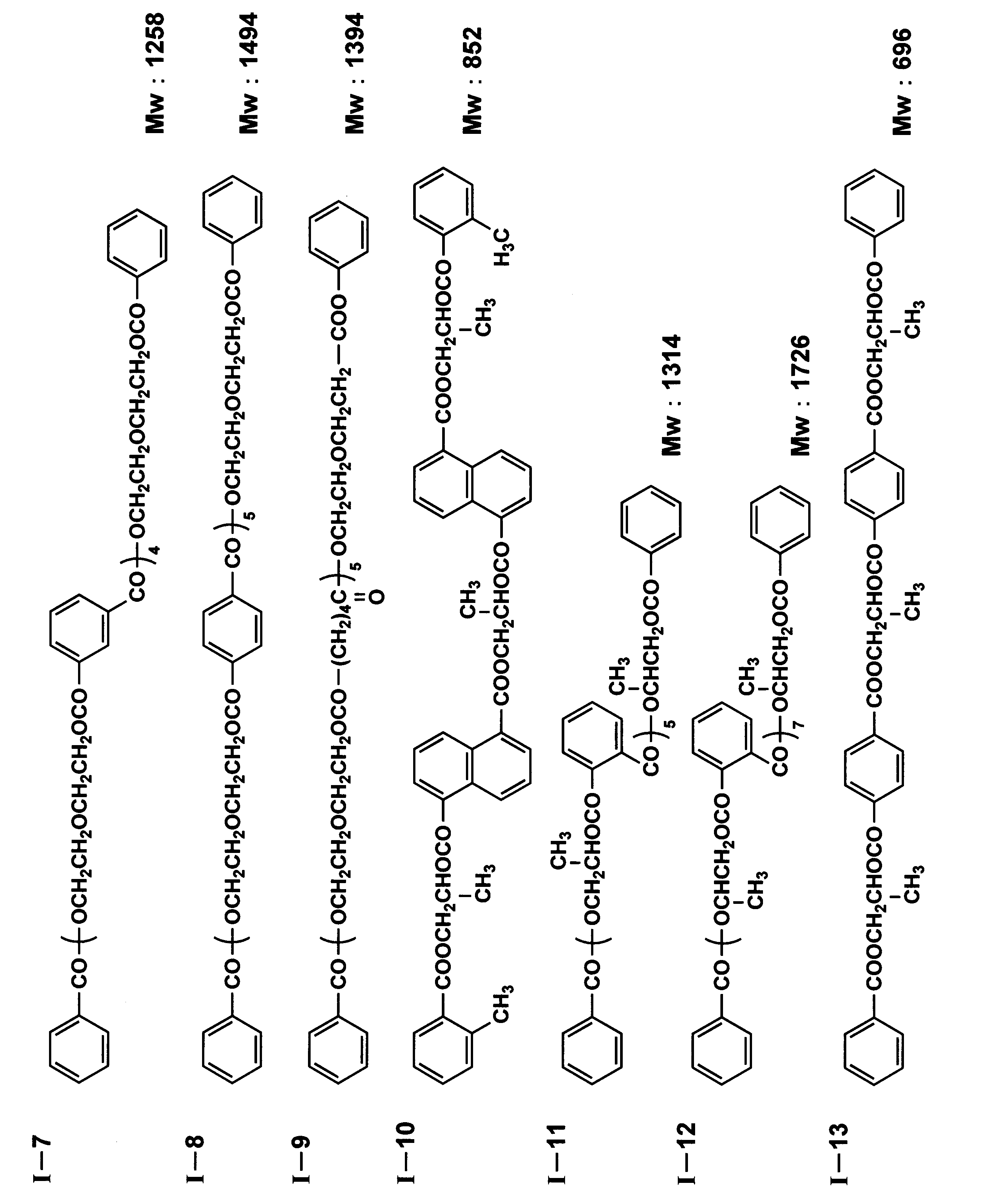
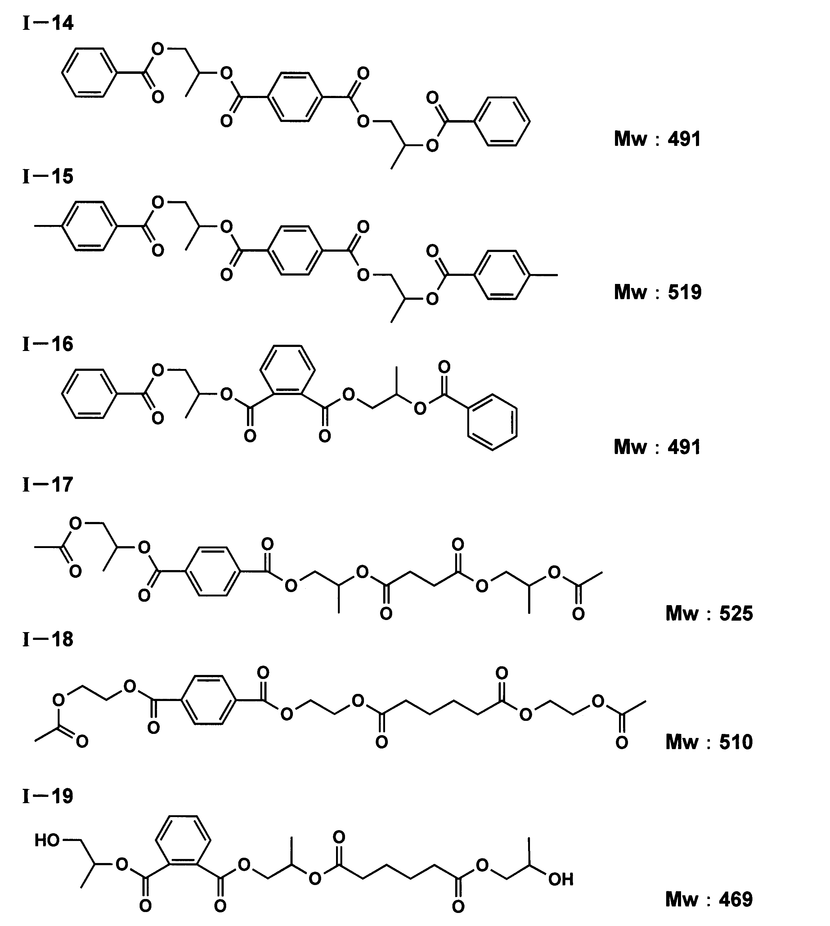
以下に、本発明に係るジカルボン酸とジオールとの重縮合物であるポリエステルP1~P8の合成の一例を示す。
〈ポリエステルP1の合成〉
エチレングリコールを180g、無水フタル酸を278g、アジピン酸を91g、安息香酸を610gと、0.191gのエステル化触媒であるテトライソプロピルチタネートを、温度計、撹拌器、緩急冷却管を備えた2Lの四つ口フラスコに添加し、窒素気流中で230℃になるまで撹拌しながら徐々に昇温し、重合度を観察しながら脱水縮合反応させた。反応終了後、200℃で未反応のエチレングリコールを減圧留去することにより、ポリエステルP1を得た。ポリエステルP1の酸価は0.20(KOHmg/g)、数平均分子量は450であった。
エチレングリコールを180g、無水フタル酸を278g、アジピン酸を91g、安息香酸を610gと、0.191gのエステル化触媒であるテトライソプロピルチタネートを、温度計、撹拌器、緩急冷却管を備えた2Lの四つ口フラスコに添加し、窒素気流中で230℃になるまで撹拌しながら徐々に昇温し、重合度を観察しながら脱水縮合反応させた。反応終了後、200℃で未反応のエチレングリコールを減圧留去することにより、ポリエステルP1を得た。ポリエステルP1の酸価は0.20(KOHmg/g)、数平均分子量は450であった。
〈ポリエステルP2の合成〉
1,2-プロピレングリコールを251g、無水フタル酸を244g、アジピン酸を103g、安息香酸を610gと、エステル化触媒として0.191gのテトライソプロピルチタネートを、温度計、撹拌器、緩急冷却管を備えた2Lの四つ口フラスコに添加し、窒素気流中で230℃になるまで撹拌しながら徐々に昇温し、重合度を観察しながら脱水縮合反応させた。反応終了後、200℃で未反応の1,2-プロピレングリコールを減圧留去することにより、ポリエステルP2を得た。ポリエステルP2の酸価は0.10(KOHmg/g)、数平均分子量は450であった。
1,2-プロピレングリコールを251g、無水フタル酸を244g、アジピン酸を103g、安息香酸を610gと、エステル化触媒として0.191gのテトライソプロピルチタネートを、温度計、撹拌器、緩急冷却管を備えた2Lの四つ口フラスコに添加し、窒素気流中で230℃になるまで撹拌しながら徐々に昇温し、重合度を観察しながら脱水縮合反応させた。反応終了後、200℃で未反応の1,2-プロピレングリコールを減圧留去することにより、ポリエステルP2を得た。ポリエステルP2の酸価は0.10(KOHmg/g)、数平均分子量は450であった。
〈ポリエステルP3の合成〉
1,4-ブタンジオールを330g、無水フタル酸を244g、アジピン酸を103g、安息香酸を610gと、エステル化触媒として0.191gのテトライソプロピルチタネートを、温度計、撹拌器、緩急冷却管を備えた2Lの四つ口フラスコに添加し、窒素気流中で230℃になるまで、撹拌しながら徐々に昇温し、重合度を観察しながら脱水縮合反応させた。反応終了後、200℃で未反応の1,4-ブタンジオールを減圧留去することにより、ポリエステルP3を得た。ポリエステルP3の酸価は0.50(KOHmg/g)、数平均分子量は2000であった。
1,4-ブタンジオールを330g、無水フタル酸を244g、アジピン酸を103g、安息香酸を610gと、エステル化触媒として0.191gのテトライソプロピルチタネートを、温度計、撹拌器、緩急冷却管を備えた2Lの四つ口フラスコに添加し、窒素気流中で230℃になるまで、撹拌しながら徐々に昇温し、重合度を観察しながら脱水縮合反応させた。反応終了後、200℃で未反応の1,4-ブタンジオールを減圧留去することにより、ポリエステルP3を得た。ポリエステルP3の酸価は0.50(KOHmg/g)、数平均分子量は2000であった。
〈ポリエステルP4の合成〉
1,2-プロピレングリコールを251g、テレフタル酸を354g、安息香酸を610gと、エステル化触媒として0.191gのテトライソプロピルチタネートを、温度計、撹拌器、緩急冷却管を備えた2Lの四つ口フラスコに添加し、窒素気流中で230℃になるまで撹拌しながら徐々に昇温し、重合度を観察しながら脱水縮合反応させた。反応終了後、200℃で未反応の1,2-プロピレングリコールを減圧留去することにより、ポリエステルP4を得た。ポリエステルP4の酸価は0.10(KOHmg/g)、数平均分子量は400であった。
1,2-プロピレングリコールを251g、テレフタル酸を354g、安息香酸を610gと、エステル化触媒として0.191gのテトライソプロピルチタネートを、温度計、撹拌器、緩急冷却管を備えた2Lの四つ口フラスコに添加し、窒素気流中で230℃になるまで撹拌しながら徐々に昇温し、重合度を観察しながら脱水縮合反応させた。反応終了後、200℃で未反応の1,2-プロピレングリコールを減圧留去することにより、ポリエステルP4を得た。ポリエステルP4の酸価は0.10(KOHmg/g)、数平均分子量は400であった。
〈ポリエステルP5の合成〉
1,2-プロピレングリコールを251g、テレフタル酸を354g、p-トロイル酸を680gと、エステル化触媒として0.191gのテトライソプロピルチタネートを、温度計、撹拌器、緩急冷却管を備えた2Lの四つ口フラスコに添加し、窒素気流中で230℃になるまで撹拌しながら徐々に昇温し、重合度を観察しながら脱水縮合反応させた。反応終了後、200℃で未反応の1,2-プロピレングリコールを減圧留去することにより、ポリエステルP5を得た。ポリエステルP5の酸価は0.30(KOHmg/g)、数平均分子量は400であった。
1,2-プロピレングリコールを251g、テレフタル酸を354g、p-トロイル酸を680gと、エステル化触媒として0.191gのテトライソプロピルチタネートを、温度計、撹拌器、緩急冷却管を備えた2Lの四つ口フラスコに添加し、窒素気流中で230℃になるまで撹拌しながら徐々に昇温し、重合度を観察しながら脱水縮合反応させた。反応終了後、200℃で未反応の1,2-プロピレングリコールを減圧留去することにより、ポリエステルP5を得た。ポリエステルP5の酸価は0.30(KOHmg/g)、数平均分子量は400であった。
〈ポリエステルP6の合成〉
1,2-プロピレングリコールを180g、アジピン酸を292gと、エステル化触媒として0.191gのテトライソプロピルチタネートを、温度計、撹拌器、緩急冷却管を備えた2Lの四つ口フラスコに添加し、窒素気流中で200℃になるまで、撹拌しながら徐々に昇温し、重合度を観察しながら脱水縮合反応させた。反応終了後、200℃で未反応の1,2-プロピレングリコールを減圧留去することにより、ポリエステルP6を得た。ポリエステルP6の酸価は0.10(KOHmg/g)、数平均分子量は400であった。
1,2-プロピレングリコールを180g、アジピン酸を292gと、エステル化触媒として0.191gのテトライソプロピルチタネートを、温度計、撹拌器、緩急冷却管を備えた2Lの四つ口フラスコに添加し、窒素気流中で200℃になるまで、撹拌しながら徐々に昇温し、重合度を観察しながら脱水縮合反応させた。反応終了後、200℃で未反応の1,2-プロピレングリコールを減圧留去することにより、ポリエステルP6を得た。ポリエステルP6の酸価は0.10(KOHmg/g)、数平均分子量は400であった。
〈ポリエステルP7の合成〉
エチレングリコールを160g、アジピン酸を292gと、エステル化触媒として0.191gのテトライソプロピルチタネートを、温度計、撹拌器、緩急冷却管を備えた2Lの四つ口フラスコに添加し、窒素気流中で200℃になるまで、撹拌しながら徐々に昇温し、重合度を観察しながら脱水縮合反応させた。反応終了後、200℃で未反応のエチレングリコールを減圧留去することにより、ポリエステルP7を得た。ポリエステルP7の酸価は0.10(KOHmg/g)、数平均分子量は1000であった。
エチレングリコールを160g、アジピン酸を292gと、エステル化触媒として0.191gのテトライソプロピルチタネートを、温度計、撹拌器、緩急冷却管を備えた2Lの四つ口フラスコに添加し、窒素気流中で200℃になるまで、撹拌しながら徐々に昇温し、重合度を観察しながら脱水縮合反応させた。反応終了後、200℃で未反応のエチレングリコールを減圧留去することにより、ポリエステルP7を得た。ポリエステルP7の酸価は0.10(KOHmg/g)、数平均分子量は1000であった。
〈ポリエステルP8の合成〉
エチレングリコールを251g、無水フタル酸を244g、セバシン酸を200g、安息香酸を610gと、エステル化触媒として0.191gのテトライソプロピルチタネートを、温度計、撹拌器、緩急冷却管を備えた2Lの四つ口フラスコに添加し、窒素気流中で230℃になるまで、撹拌しながら徐々に昇温し、重合度を観察しながら脱水縮合反応させた。反応終了後、200℃で未反応のエチレングリコールを減圧留去することにより、ポリエステルP8を得た。ポリエステルP8の酸価は0.50(KOHmg/g)、数平均分子量は2000であった。
エチレングリコールを251g、無水フタル酸を244g、セバシン酸を200g、安息香酸を610gと、エステル化触媒として0.191gのテトライソプロピルチタネートを、温度計、撹拌器、緩急冷却管を備えた2Lの四つ口フラスコに添加し、窒素気流中で230℃になるまで、撹拌しながら徐々に昇温し、重合度を観察しながら脱水縮合反応させた。反応終了後、200℃で未反応のエチレングリコールを減圧留去することにより、ポリエステルP8を得た。ポリエステルP8の酸価は0.50(KOHmg/g)、数平均分子量は2000であった。
本発明において、ジカルボン酸とジオールとの重縮合物の保護フィルムAであるセルロースエステルフィルムにおける含有量は、好ましくは1~40質量%の範囲内であり、より好ましくは1.5~15質量%の範囲内であり、さらに好ましくは2~12質量%の範囲内である。上記範囲内であると、可塑性としての付与効果が発現でき、本発明に係るセルロースエステルフィルムのマルテンス硬度を所望の条件に制御しやすくなる。
〔その他の添加剤〕
本発明に係るセルロースエステルフィルム(セルロースアセテートフィルム)においては、(1)糖エステル、既に上記でその詳細を説明した(2)ジカルボン酸とジオールとの重縮合物、(3)リン酸エステル化合物、(4)脂肪族多価アルコールとモノカルボン酸のエステル類、及び(5)グリコール酸のエステル類の化合物群の中から、少なくとも3種の化合物を含有することが、マルテンス硬度を本発明で規定する範囲内に制御しやすくなる観点から好ましい。
本発明に係るセルロースエステルフィルム(セルロースアセテートフィルム)においては、(1)糖エステル、既に上記でその詳細を説明した(2)ジカルボン酸とジオールとの重縮合物、(3)リン酸エステル化合物、(4)脂肪族多価アルコールとモノカルボン酸のエステル類、及び(5)グリコール酸のエステル類の化合物群の中から、少なくとも3種の化合物を含有することが、マルテンス硬度を本発明で規定する範囲内に制御しやすくなる観点から好ましい。
(1)糖エステル
本発明に係るセルロースエステルフィルム(セルロースアセテートフィルム)においては、セルロースエステル以外の糖エステルを含有することが好ましい。
本発明に係るセルロースエステルフィルム(セルロースアセテートフィルム)においては、セルロースエステル以外の糖エステルを含有することが好ましい。
本発明に係る糖エステルとしては、ピラノース環又はフラノース環の少なくとも1種を1個以上、12個以下有し、その構造のOH基の全て若しくは一部をエステル化した糖エステルであることが好ましい。
本発明に係る糖エステルとは、フラノース環及びピラノース環の少なくとも一つを含む化合物であり、単糖類であっても、糖構造が2~12個連結した多糖類であってもよい。そして、糖エステルは、糖構造が有するOH基の少なくとも一つがエステル化された化合物が好ましい。糖エステルのエステル化率は、ピラノース環又はフラノース環内に存在するOH基の50%以上であることが好ましく、60%以上であることがより好ましく、80%以上であることが特に好ましい。50%以上であれば、セルロースエステルフィルムを成膜する際の延伸及び乾燥工程において、熱でフィルムが着色するのを防止することができる。
本発明に係るセルロースエステルフィルムは、マルテンス硬度を制御する観点から、糖エステルをセルロースエステルフィルムに対して1~30質量%の範囲で含有することが好ましく、5~30質量%の範囲で含有することがより好ましい。
糖エステルを構成する糖の例には、グルコース、ガラクトース、マンノース、フルクトース、キシロース、あるいはアラビノース、ラクトース、スクロース、ニストース、1F-フラクトシルニストース、スタキオース、マルチトール、ラクチトール、ラクチュロース、セロビオース、マルトース、セロトリオース、マルトトリオース、ラフィノースあるいはケストースなどが含まれる。さらに、糖エステルを構成する糖の例には、ゲンチオビオース、ゲンチオトリオース、ゲンチオテトラオース、キシロトリオース、ガラクトシルスクロースなども含まれる。もちろん、糖はこれらに限定されない。糖エステルを構成する糖構造は、特にピラノース環とフラノース環を両方含むことが好ましい。
糖エステルを構成する糖の好ましい例は、スクロース、ケストース、ニストース、1F-フラクトシルニストース、スタキオースなどであり、更に好ましくは、スクロースである。
糖エステルでは、ピラノース環又はフラノース環中のOH基の全て又は一部がエステル化されている。エステル化のためのモノカルボン酸は、特に制限はなく、公知の脂肪族モノカルボン酸、脂環族モノカルボン酸、芳香族モノカルボン酸等を用いることができる。用いられるカルボン酸は1種類でもよいし、2種以上の混合であってもよい。
糖エステルのエステルを構成する好ましい脂肪族モノカルボン酸の例には、酢酸、プロピオン酸、酪酸、イソ酪酸、吉草酸、カプロン酸、エナント酸、カプリル酸、ペラルゴン酸、カプリン酸、2-エチル-ヘキサンカルボン酸、ウンデシル酸、ラウリン酸、トリデシル酸、ミリスチン酸、ペンタデシル酸、パルミチン酸、ヘプタデシル酸、ステアリン酸、ノナデカン酸、アラキン酸、ベヘン酸、リグノセリン酸、セロチン酸、ヘプタコサン酸、モンタン酸、メリシン酸、ラクセル酸等の飽和脂肪酸、ウンデシレン酸、オレイン酸、ソルビン酸、リノール酸、リノレン酸、アラキドン酸、オクテン酸等の不飽和脂肪酸などが含まれる。その中でも、特に、酢酸及び酪酸が好ましい。
糖エステルのエステルを構成する好ましい脂環族モノカルボン酸の例には、シクロペンタンカルボン酸、シクロヘキサンカルボン酸、シクロオクタンカルボン酸、又はそれらの誘導体が含まれる。
糖エステルのエステルを構成する好ましい芳香族モノカルボン酸の例には、安息香酸、トルイル酸等の安息香酸のベンゼン環にアルキル基、アルコキシ基を導入した芳香族モノカルボン酸、ケイ皮酸、ベンジル酸、ビフェニルカルボン酸、ナフタリンカルボン酸、テトラリンカルボン酸等のベンゼン環を2個以上有する芳香族モノカルボン酸、又はそれらの誘導体が含まれる。より具体的には、キシリル酸、ヘメリト酸、メシチレン酸、プレーニチル酸、γ-イソジュリル酸、ジュリル酸、メシト酸、α-イソジュリル酸、クミン酸、α-トルイル酸、ヒドロアトロパ酸、アトロパ酸、ヒドロケイ皮酸、サリチル酸、o-アニス酸、m-アニス酸、p-アニス酸、クレオソート酸、o-ホモサリチル酸、m-ホモサリチル酸、p-ホモサリチル酸、o-ピロカテク酸、β-レソルシル酸、バニリン酸、イソバニリン酸、ベラトルム酸、o-ベラトルム酸、没食子酸、アサロン酸、マンデル酸、ホモアニス酸、ホモバニリン酸、ホモベラトルム酸、o-ホモベラトルム酸、フタロン酸、p-クマル酸が含まれ、特に安息香酸が好ましい。また、芳香族者カルボン酸を有した糖エステルと、脂肪族を有した糖エステルとを混合して用いることも好ましい。
オリゴ糖のエステル化合物は、本発明における糖エステルとして用いることができる。オリゴ糖は、デンプン、ショ糖等にアミラーゼなどの酵素を作用させて製造されるもので、好ましいオリゴ糖の例には、マルトオリゴ糖、イソマルトオリゴ糖、フラクトオリゴ糖、ガラクトオリゴ糖、キシロオリゴ糖が挙げられる。
糖エステルは、下記一般式(A)で表されるピラノース環又はフラノース環の少なくとも1種を、1個以上、12個以下縮合した化合物である。一般式(A)におけるR11~R15、R21~R25は、各々炭素数が2~22のアシル基又は水素原子を表し、m及びnは各々0~12の整数であり、m+nは1~12の整数である。
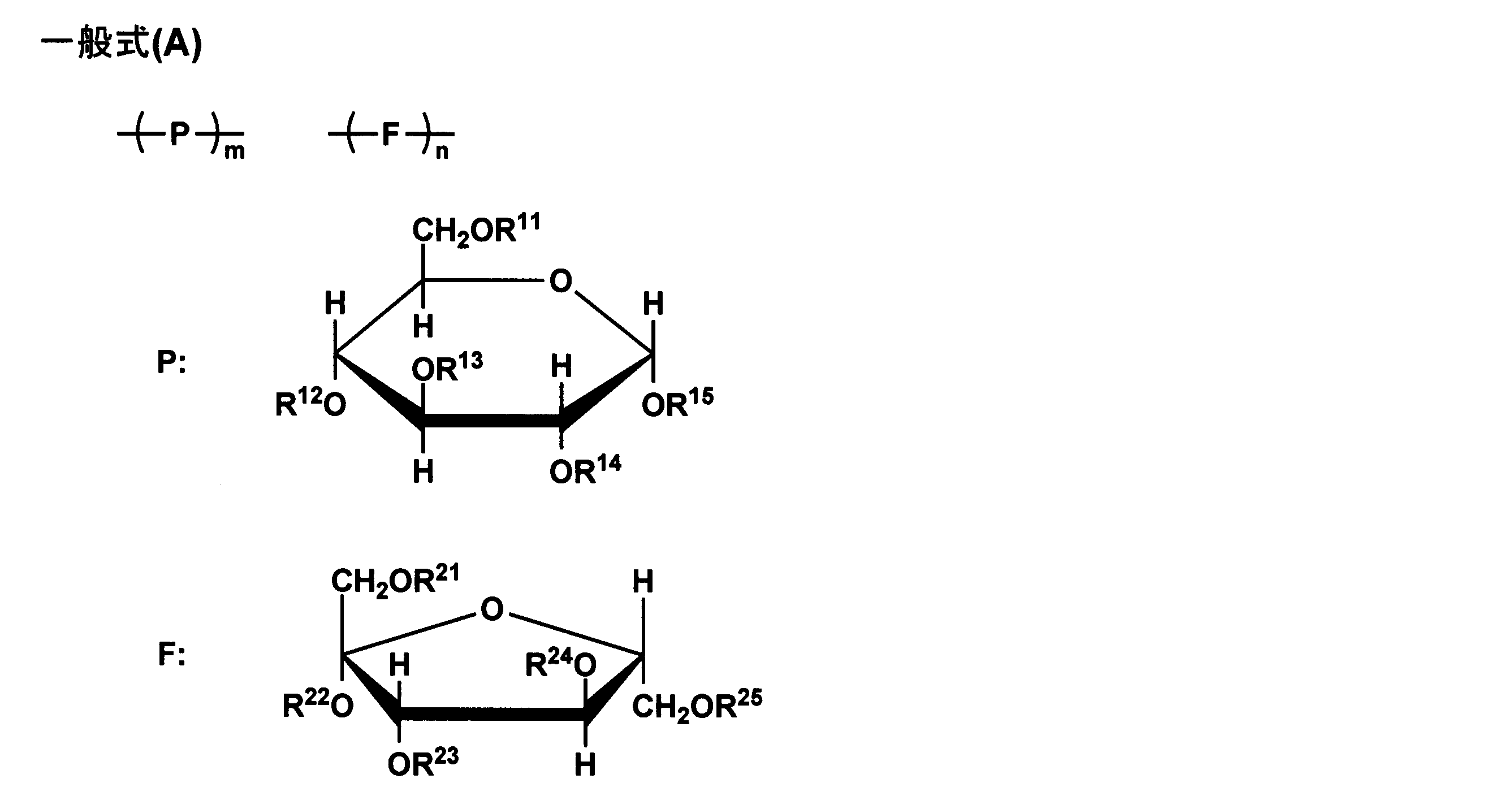
上記一般式(A)において、R11~R15、R21~R25は、各々ベンゾイル基又は水素原子であることが好ましい。ベンゾイル基は置換基を有していてもよく、例えば、置換基として、アルキル基、アルケニル基、アルコキシル基、フェニル基が挙げられ、更にこれらのアルキル基、アルケニル基、フェニル基は置換基を有していてもよい。オリゴ糖のエステル化合物も、他の糖エステルと同様な方法で製造することができる。
本発明に係る糖エステルは、脂肪族アルキル基又は芳香族アルキル基の置換基を有し、脂肪族アルキル基の数をAL、及び芳香族アルキル基の数をARとしたときに、当該脂肪族アルキル基の数が当該芳香族アルキル基の数より多い(AR<AL)ことが、本発明の目的効果をより発現できる観点から好ましい。
以下に、本発明に係る糖エステルの具体例として化合物1~化合物24を挙げるが、本発明はこれに限定されるものではない。


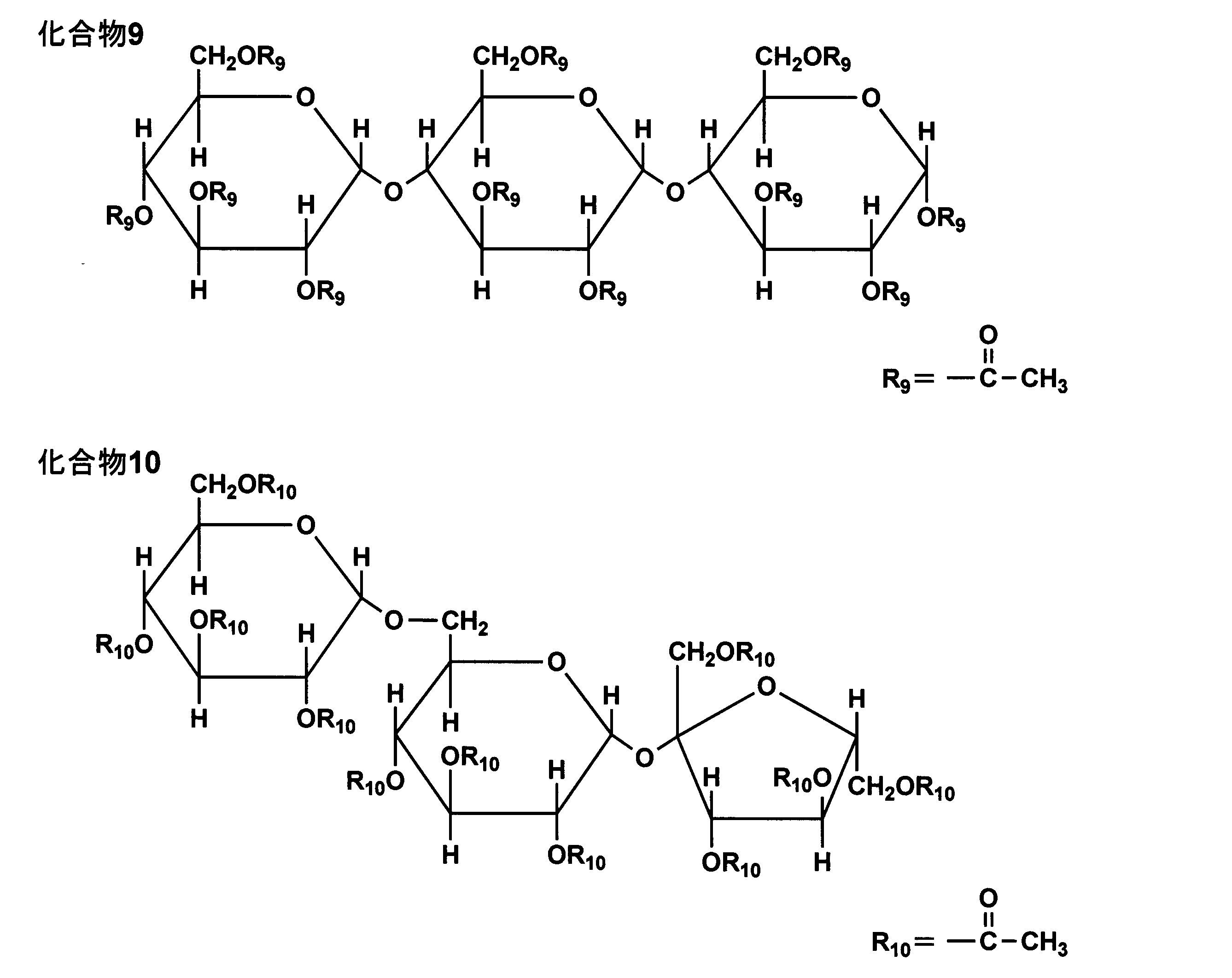


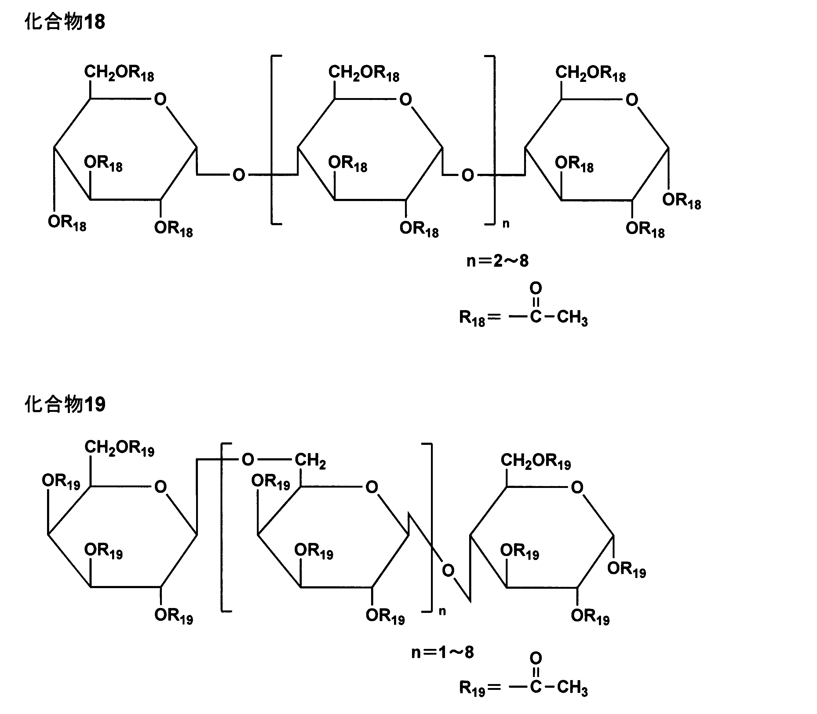

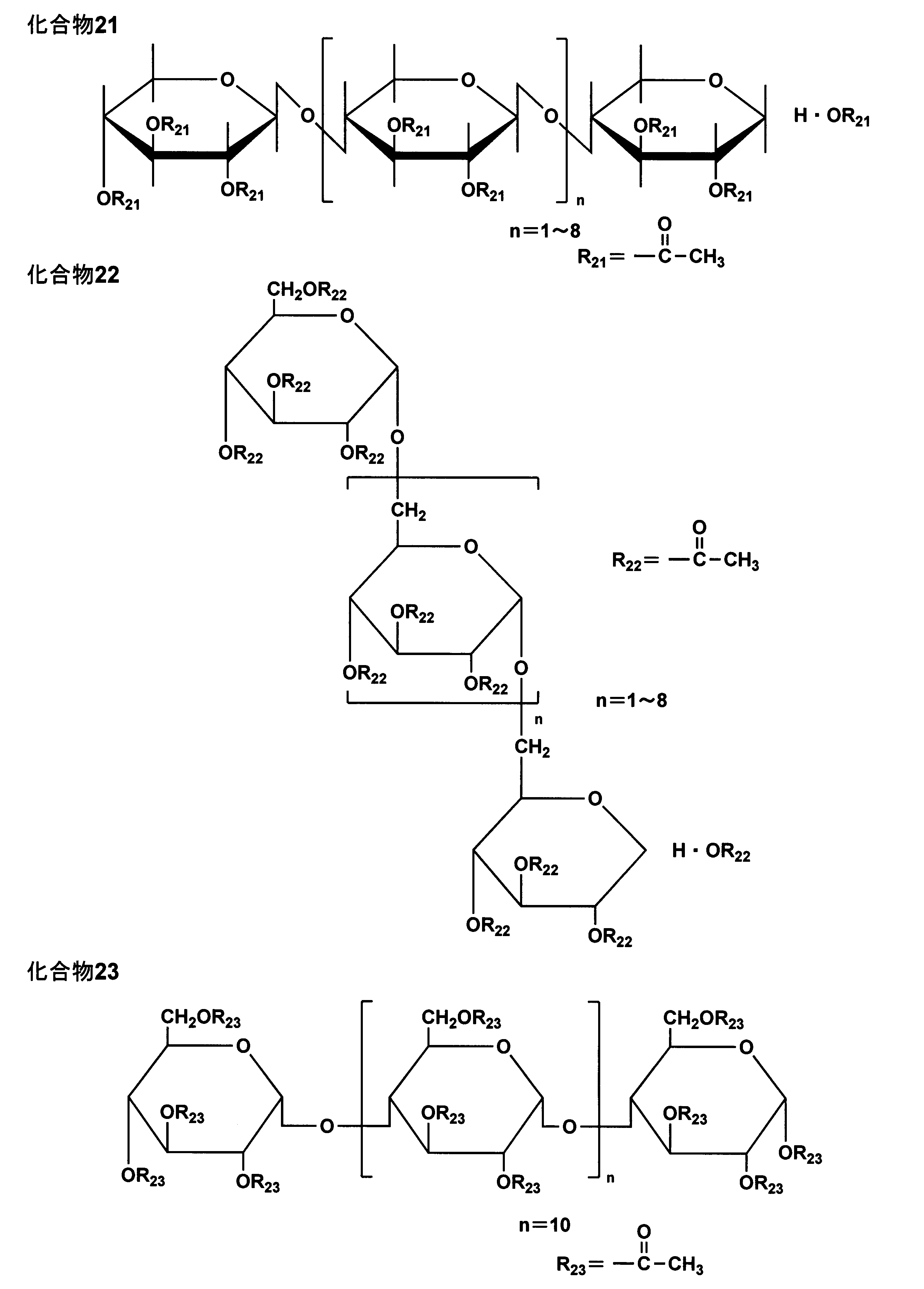

本発明に係る糖エステルは、前述の糖に、アシル化剤(エステル化剤ともいい、例えば、アセチルクロライドの酸ハロゲン化物、無水酢酸等の無水物等が挙げられる。)を反応させることによって製造することが可能である。置換度の分布は、アシル化剤の量、添加タイミング、エステル化反応時間の調節によってなされるが、置換度違いの糖エステルの混合、あるいは純粋に単離した置換度違いの化合物を混合することが好ましい。
(3)リン酸エステル化合物
本発明に適用可能なリン酸エステル化合物としては、トリアリールリン酸エステル、ジアリールリン酸エステル、モノアリールリン酸エステル、アリールホスホン酸化合物、アリールホスフィンオキシド化合物、縮合アリールリン酸エステル、ハロゲン化アルキルリン酸エステル、含ハロゲン縮合リン酸エステル、含ハロゲン縮合ホスホン酸エステル、含ハロゲン亜リン酸エステル等が挙げることができる。
本発明に適用可能なリン酸エステル化合物としては、トリアリールリン酸エステル、ジアリールリン酸エステル、モノアリールリン酸エステル、アリールホスホン酸化合物、アリールホスフィンオキシド化合物、縮合アリールリン酸エステル、ハロゲン化アルキルリン酸エステル、含ハロゲン縮合リン酸エステル、含ハロゲン縮合ホスホン酸エステル、含ハロゲン亜リン酸エステル等が挙げることができる。
具体的なリン酸エステル化合物としては、トリフェニルホスフェート、9,10-ジヒドロ-9-オキサ-10-ホスファフェナンスレン-10-オキシド、フェニルホスホン酸、トリス(β-クロロエチル)ホスフェート、トリス(ジクロロプロピル)ホスフェート、トリス(トリブロモネオペンチル)ホスフェート等が挙げられる。
(4)脂肪族多価アルコールとモノカルボン酸のエステル類
本発明に係る保護フィルムAを構成するセルロースエステルフィルムにおいては、多価アルコールエステル類を適用することが好ましいが、本発明に適用可能な多価アルコールエステル類の一つとしては、2価以上の脂肪族多価アルコールとモノカルボン酸のエステルとからなる化合物(以下、本発明に係る多価アルコールエステル類ともいう。)であり、分子内に芳香環又はシクロアルキル環を有する化合物が好ましい。好ましくは2~20価の脂肪族多価アルコールエステルである。
本発明に係る保護フィルムAを構成するセルロースエステルフィルムにおいては、多価アルコールエステル類を適用することが好ましいが、本発明に適用可能な多価アルコールエステル類の一つとしては、2価以上の脂肪族多価アルコールとモノカルボン酸のエステルとからなる化合物(以下、本発明に係る多価アルコールエステル類ともいう。)であり、分子内に芳香環又はシクロアルキル環を有する化合物が好ましい。好ましくは2~20価の脂肪族多価アルコールエステルである。
本発明に係る多価アルコールエステル類の形成に好ましく用いられる多価アルコールの一例としては、下記一般式(III)で表される化合物である。
一般式(III)
R11-(OH)n
式中、R11はn価の有機基を表す。nは2以上の整数を表す。OH基はアルコール性又はフェノール性ヒドロキシ基(水酸基)を表す。
R11-(OH)n
式中、R11はn価の有機基を表す。nは2以上の整数を表す。OH基はアルコール性又はフェノール性ヒドロキシ基(水酸基)を表す。
好ましい多価アルコールとしては、例えば、アドニトール、アラビトール、エチレングリコール、ジエチレングリコール、トリエチレングリコール、テトラエチレングリコール、1,2-プロパンジオール、1,3-プロパンジオール、ジプロピレングリコール、トリプロピレングリコール、1,2-ブタンジオール、1,3-ブタンジオール、1,4-ブタンジオール、ジブチレングリコール、1,2,4-ブタントリオール、1,5-ペンタンジオール、1,6-ヘキサンジオール、ヘキサントリオール、ガラクチトール、マンニトール、3-メチルペンタン-1,3,5-トリオール、ピナコール、ソルビトール、トリメチロールプロパン、トリメチロールエタン、キシリトール等が挙げられる。特に、トリエチレングリコール、テトラエチレングリコール、ジプロピレングリコール、トリプロピレングリコール、ソルビトール、トリメチロールプロパン、キシリトールが好ましい。
本発明に係る多価アルコールエステルに用いられるモノカルボン酸としては、特に制限はなく、公知の脂肪族モノカルボン酸、脂環族モノカルボン酸、芳香族モノカルボン酸等を用いることができる。脂環族モノカルボン酸、芳香族モノカルボン酸を用いると透湿性、保留性を向上させる点で好ましい。
好ましいモノカルボン酸の例としては以下のようなものを挙げることができるが、本発明はこれに限定されるものではない。
脂肪族モノカルボン酸としては、炭素数が1~32の直鎖又は側鎖を有する脂肪酸を好ましく用いることができる。炭素数は1~20であることがさらに好ましく、炭素数が1~10であることが特に好ましい。
好ましい脂肪族モノカルボン酸としては、酢酸、プロピオン酸、酪酸、吉草酸、カプロン酸、エナント酸、カプリル酸、ペラルゴン酸、カプリン酸、2-エチル-ヘキサン酸、ウンデシル酸、ラウリン酸、トリデシル酸、ミリスチン酸、ペンタデシル酸、パルミチン酸、ヘプタデシル酸、ステアリン酸、ノナデカン酸、アラキン酸、ベヘン酸、リグノセリン酸、セロチン酸、ヘプタコサン酸、モンタン酸、メリシン酸、ラクセル酸等の飽和脂肪酸、ウンデシレン酸、オレイン酸、ソルビン酸、リノール酸、リノレン酸、アラキドン酸等の不飽和脂肪酸等を挙げることができる。その中でも、酢酸を含有させることが、セルロースアシレートとの相溶性が増すため好ましく、酢酸と他のモノカルボン酸を混合して用いることも好ましい。
好ましい脂環族モノカルボン酸の例としては、シクロペンタンカルボン酸、シクロヘキサンカルボン酸、シクロオクタンカルボン酸、又はそれらの誘導体を挙げることができる。
好ましい芳香族モノカルボン酸の例としては、安息香酸、トルイル酸等の安息香酸のベンゼン環にアルキル基、メトキシ基又はエトキシ基等のアルコキシ基を1~3個を導入したもの、ビフェニルカルボン酸、ナフタリンカルボン酸、テトラリンカルボン酸等のベンゼン環を2個以上有する芳香族モノカルボン酸、又はそれらの誘導体を挙げることができる。特に安息香酸が好ましい。
本発明に係る多価アルコールエステル類の分子量は、特に制限はないが、300~1500の範囲内であることが好ましく、350~750の範囲内であることがさらに好ましい。分子量が1500以下であれば、揮発し難くなるため好ましく、分子量が300以上であれば、透湿性、セルロースアシレートとの相溶性の点では好ましい。
本発明に係る多価アルコールエステル類に用いられるカルボン酸は1種類でもよいし、2種以上の混合であってもよい。また、多価アルコール中のOH基は、全てエステル化してもよいし、一部を未置換の状態でOH基として残してもよい。
以下に、本発明に適用可能な多価アルコールエステル類の具体的化合物(ae-1)~(ae-34)を例示する。
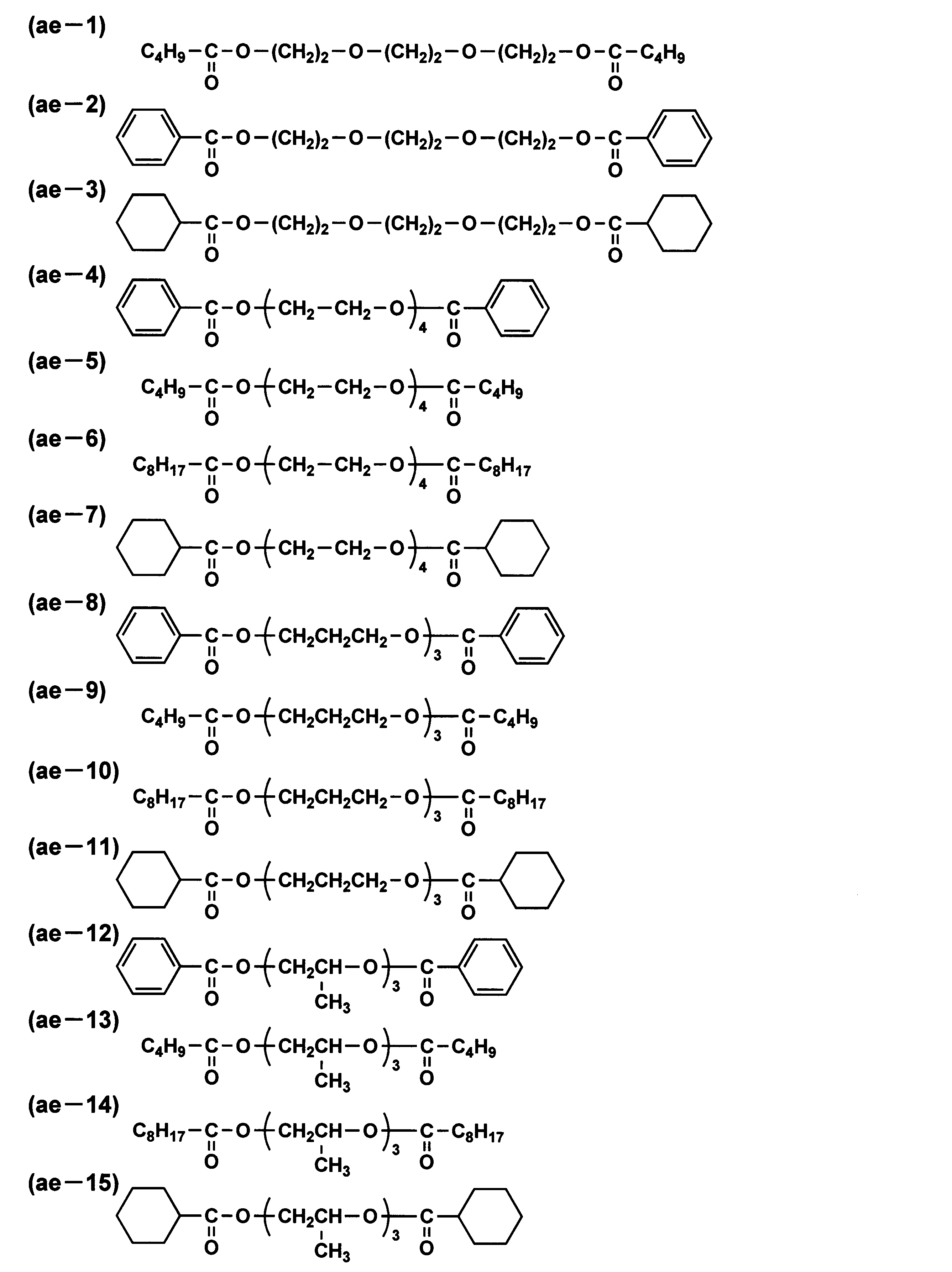
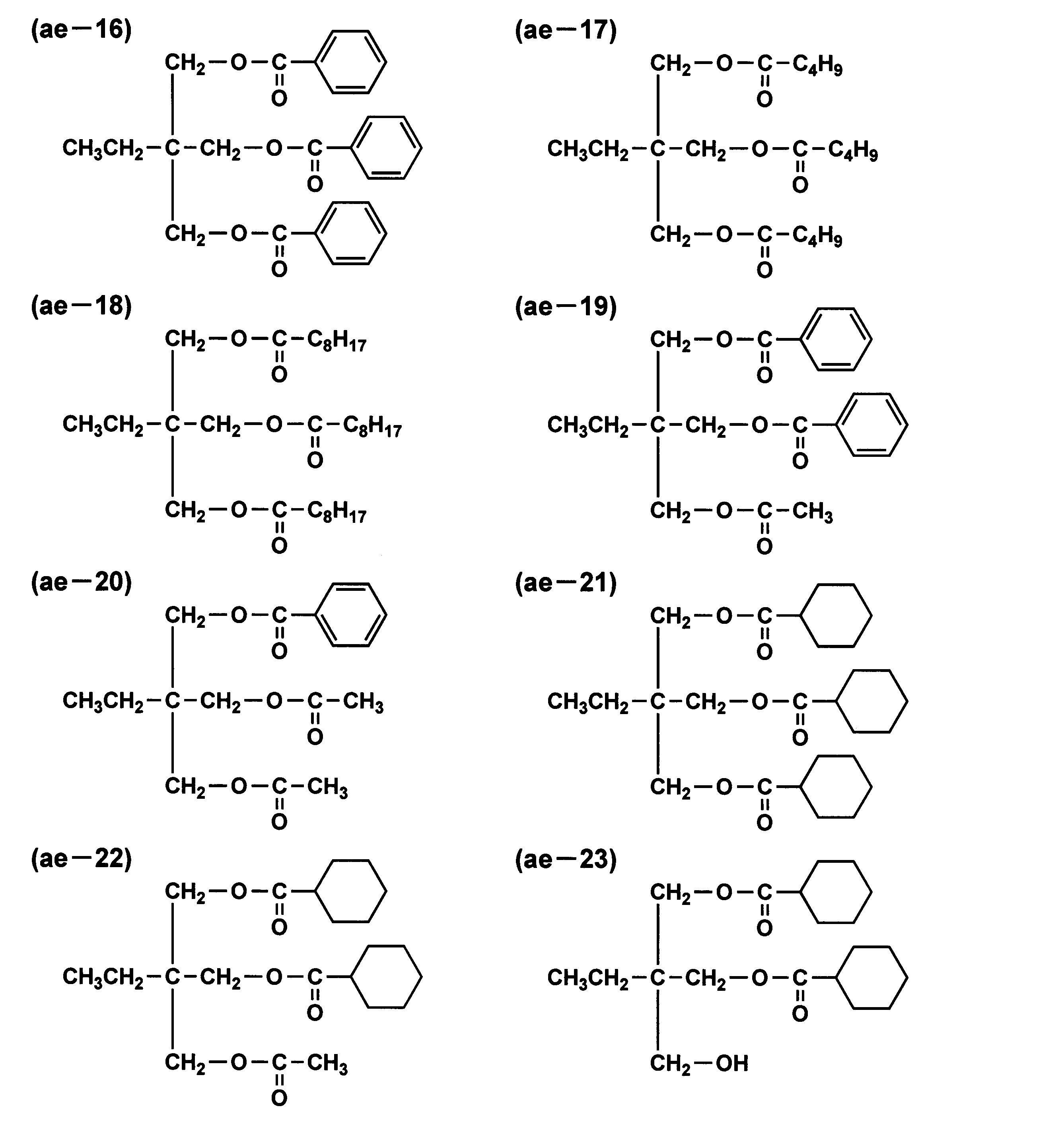

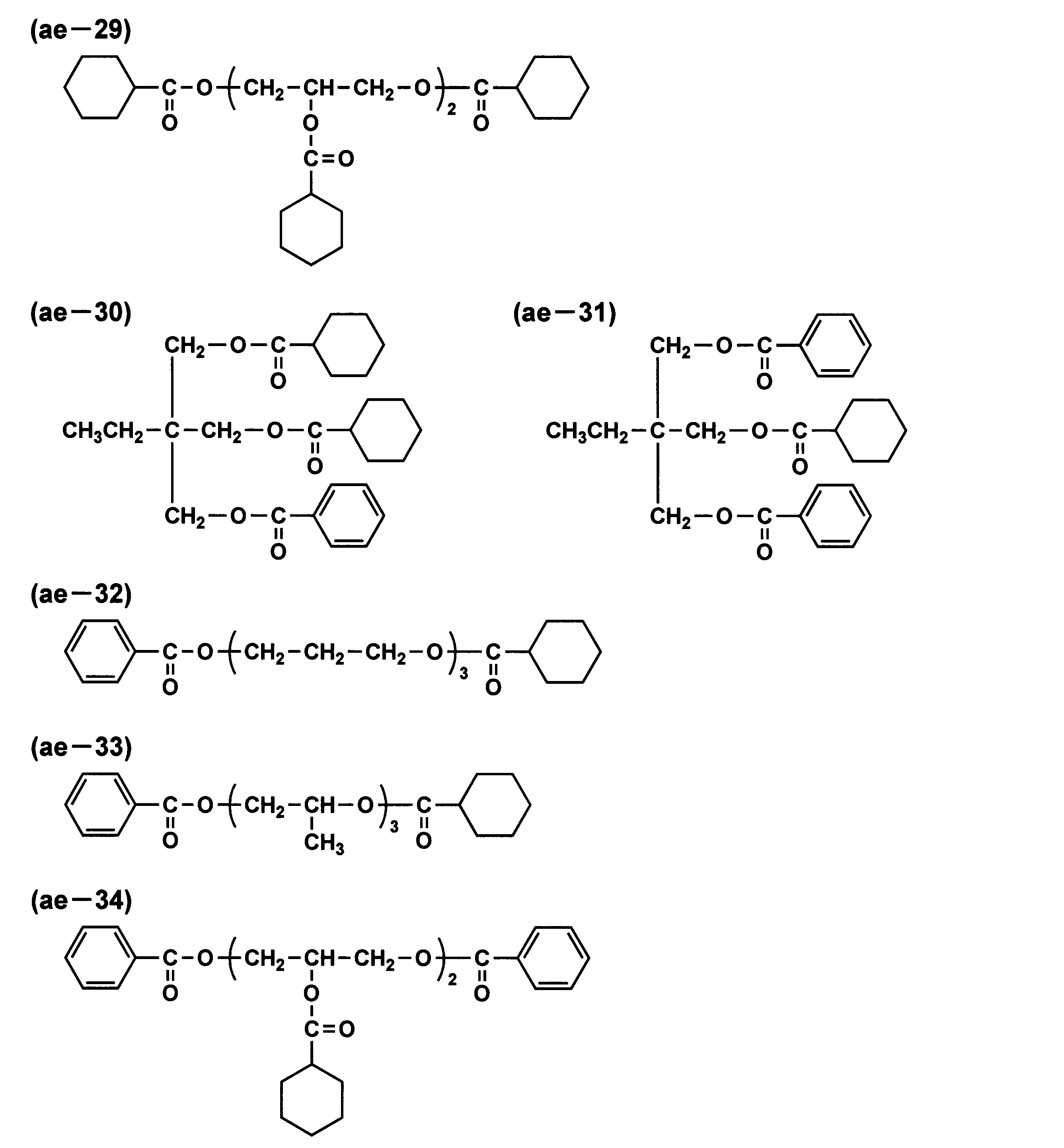
(5)グリコール酸のエステル類
また、本発明においては、多価アルコールエステル類の一種として、グリコール酸のエステル類(グリコレート化合物)を用いることが好ましい。
また、本発明においては、多価アルコールエステル類の一種として、グリコール酸のエステル類(グリコレート化合物)を用いることが好ましい。
本発明に適用可能なグリコレート化合物としては、特に限定されないが、アルキルフタリルアルキルグリコレート類が好ましく用いることができる。
アルキルフタリルアルキルグリコレート類としては、例えば、メチルフタリルメチルグリコレート、エチルフタリルエチルグリコレート、プロピルフタリルプロピルグリコレート、ブチルフタリルブチルグリコレート、オクチルフタリルオクチルグリコレート、メチルフタリルエチルグリコレート、エチルフタリルメチルグリコレート、エチルフタリルプロピルグリコレート、メチルフタリルブチルグリコレート、エチルフタリルブチルグリコレート、ブチルフタリルメチルグリコレート、ブチルフタリルエチルグリコレート、プロピルフタリルブチルグリコレート、ブチルフタリルプロピルグリコレート、メチルフタリルオクチルグリコレート、エチルフタリルオクチルグリコレート、オクチルフタリルメチルグリコレート、オクチルフタリルエチルグリコレート等が挙げられ、好ましくはエチルフタリルエチルグリコレートである。
(6)可塑剤
本発明に係るセルロースエステルフィルムには、上記糖エステル、ジカルボン酸とジオールの縮合物、リン酸エステル化合物、脂肪族多価アルコールとモノカルボン酸のエステル類、グリコール酸のエステル類以外に、分子量が10000以下の公知の可塑剤の効果を阻害しない範囲で用いることもできる。
本発明に係るセルロースエステルフィルムには、上記糖エステル、ジカルボン酸とジオールの縮合物、リン酸エステル化合物、脂肪族多価アルコールとモノカルボン酸のエステル類、グリコール酸のエステル類以外に、分子量が10000以下の公知の可塑剤の効果を阻害しない範囲で用いることもできる。
可塑剤の含有量は、セルロースエステル(セルロースアセテート)に対して好ましくは1~20質量%の範囲であり、より好ましくは4.0~15質量%の範囲である。可塑剤の含有量が上記範囲内であると、可塑性の付与効果が発現でき、セルロースエステルフィルムからの可塑剤の耐染みだし性にも優れる。
(7)その他の添加剤
〈7.1〉紫外線吸収剤
本発明に係るセルロースエステルフィルムには、液晶表示装置の表面側(視認側)に配置する保護フィルムAとして用いるものであり、紫外線吸収剤を含有することが耐光性を向上する観点から好ましい。紫外線吸収剤は400nm以下の紫外線を吸収することで、耐光性を向上させることを目的としており、特に波長370nmにおける透過率が10%以下であることが好ましく、より好ましくは5%以下、更に好ましくは2%以下である。
〈7.1〉紫外線吸収剤
本発明に係るセルロースエステルフィルムには、液晶表示装置の表面側(視認側)に配置する保護フィルムAとして用いるものであり、紫外線吸収剤を含有することが耐光性を向上する観点から好ましい。紫外線吸収剤は400nm以下の紫外線を吸収することで、耐光性を向上させることを目的としており、特に波長370nmにおける透過率が10%以下であることが好ましく、より好ましくは5%以下、更に好ましくは2%以下である。
本発明で好ましく用いられる紫外線吸収剤は、ベンゾトリアゾール系紫外線吸収剤、ベンゾフェノン系紫外線吸収剤、トリアジン系紫外線吸収剤であり、特に好ましくはベンゾトリアゾール系紫外線吸収剤及びベンゾフェノン系紫外線吸収剤である。
本発明に適用可能な紫外線吸収剤の具体例としては、5-クロロ-2-(3,5-ジ-sec-ブチル-2-ヒドロキシルフェニル)-2H-ベンゾトリアゾール、(2-2H-ベンゾトリアゾール-2-イル)-6-(直鎖及び側鎖ドデシル)-4-メチルフェノール、2-ヒドロキシ-4-ベンジルオキシベンゾフェノン、2,4-ベンジルオキシベンゾフェノン等があり、また、チヌビン109、チヌビン171、チヌビン234、チヌビン326、チヌビン327、チヌビン328、チヌビン928等のチヌビン類があり、これらはいずれもBASFジャパン社製の市販品であり、好ましく使用できる。これらの紫外線吸収剤の中では、ハロゲンフリーの化合物が好ましい。
この他には、1,3,5トリアジン環を有する化合物等の円盤状化合物も紫外線吸収剤として好ましく用いられる。
本発明に係るセルロースエステルフィルムは、紫外線吸収剤を2種以上含有することが好ましい。
また、紫外線吸収剤としては高分子紫外線吸収剤も好ましく用いることができ、特に特開平6-148430号公報に記載のポリマータイプの紫外線吸収剤を好ましく用いることができる。また、紫外線吸収剤は、ハロゲン基を有していないことが好ましい。
紫外線吸収剤の添加方法は、メタノール、エタノール、ブタノール等のアルコールやメチレンクロライド、酢酸メチル、アセトン、ジオキソラン等の有機溶媒あるいはこれらの混合溶媒に紫外線吸収剤を溶解してから、セルロースエステルフィルムの成膜に用いるドープに添加するか、又は直接ドープ調製時に添加してもよい。
また、紫外線吸収剤が無機粉体のような有機溶媒に溶解しないものは、有機溶媒とセルロースエステル(セルロースアセテート)の混合液中にディゾルバーやサンドミルを使用し、分散してからドープに添加する。
紫外線吸収剤の使用量は、紫外線吸収剤の種類、使用条件等により一様ではないが、セルロースエステルフィルムの乾燥膜厚が15~50μmの範囲内である場合には、セルロースエステルフィルムに対して0.5~10質量%の範囲内で添加することが好ましく、0.6~4質量%の範囲内が更に好ましい。
〈7.2〉酸化防止剤
酸化防止剤は、劣化防止剤ともいわれている。高湿高温環境下に液晶画像表示装置などが長期間置かれた場合には、構成しているセルロースエステルフィルムの劣化が生じる場合があり、そのような劣化を防止する目的で、セルロースエステルフィルム中に酸化防止剤を添加することが好ましい。
酸化防止剤は、劣化防止剤ともいわれている。高湿高温環境下に液晶画像表示装置などが長期間置かれた場合には、構成しているセルロースエステルフィルムの劣化が生じる場合があり、そのような劣化を防止する目的で、セルロースエステルフィルム中に酸化防止剤を添加することが好ましい。
酸化防止剤は、例えば、セルロースエステルフィルム中の残留溶媒に含まれるハロゲンやリン酸系可塑剤のリン酸等によりセルロースエステルフィルムが分解するのを遅らせたり、抑制したりする役割を有する。
本発明に適用可能な酸化防止剤としては、ヒンダードフェノール系化合物が好ましく用いられ、例えば、2,6-ジ-t-ブチル-p-クレゾール、ペンタエリスリチル-テトラキス〔3-(3,5-ジ-t-ブチル-4-ヒドロキシフェニル)プロピオネート〕、トリエチレングリコール-ビス〔3-(3-t-ブチル-5-メチル-4-ヒドロキシフェニル)プロピオネート〕、1,6-ヘキサンジオール-ビス〔3-(3,5-ジ-t-ブチル-4-ヒドロキシフェニル)プロピオネート〕、2,4-ビス-(n-オクチルチオ)-6-(4-ヒドロキシ-3,5-ジ-t-ブチルアニリノ)-1,3,5-トリアジン、2,2-チオ-ジエチレンビス〔3-(3,5-ジ-t-ブチル-4-ヒドロキシフェニル)プロピオネート〕、オクタデシル-3-(3,5-ジ-t-ブチル-4-ヒドロキシフェニル)プロピオネート、N,N′-ヘキサメチレンビス(3,5-ジ-t-ブチル-4-ヒドロキシ-ヒドロシンナマミド)、1,3,5-トリメチル-2,4,6-トリス(3,5-ジ-t-ブチル-4-ヒドロキシベンジル)ベンゼン、トリス-(3,5-ジ-t-ブチル-4-ヒドロキシベンジル)-イソシアヌレイト等を挙げることができる。
特に、2,6-ジ-t-ブチル-p-クレゾール、ペンタエリスリチル-テトラキス〔3-(3,5-ジ-t-ブチル-4-ヒドロキシフェニル)プロピオネート〕、トリエチレングリコール-ビス〔3-(3-t-ブチル-5-メチル-4-ヒドロキシフェニル)プロピオネート〕が好ましい。また、例えば、N,N′-ビス〔3-(3,5-ジ-t-ブチル-4-ヒドロキシフェニル)プロピオニル〕ヒドラジン等のヒドラジン系の金属不活性剤やトリス(2,4-ジ-t-ブチルフェニル)フォスファイト等のリン系加工安定剤を併用してもよい。
これらの化合物の添加量は、セルロースエステル(セルロースアセテート)に対して質量割合で1ppm~1.0%の範囲内が好ましく、10~1000ppmの範囲内であることが更に好ましい。
〈7.3〉微粒子(マット剤)
本発明に係るセルロースエステルフィルムには、表面の滑り性を高めるため、必要に応じて微粒子(マット剤)を含有させてもよい。
本発明に係るセルロースエステルフィルムには、表面の滑り性を高めるため、必要に応じて微粒子(マット剤)を含有させてもよい。
微粒子は、無機微粒子であっても有機微粒子であってもよい。無機微粒子の例としては、二酸化ケイ素(シリカ)、二酸化チタン、酸化アルミニウム、酸化ジルコニウム、炭酸カルシウム、炭酸カルシウム、タルク、クレイ、焼成カオリン、焼成ケイ酸カルシウム、水和ケイ酸カルシウム、ケイ酸アルミニウム、ケイ酸マグネシウム及びリン酸カルシウムなどが含まれる。中でも、二酸化ケイ素や酸化ジルコニウムが好ましく、得られるフィルムのヘイズの増大を抑制することができる点から、より好ましくは二酸化ケイ素である。
二酸化ケイ素の微粒子は市販品としても入手可能であり、例えば、アエロジルR972、R972V、R974、R812、200、200V、300、R202、OX50、TT600、NAX50(以上、日本アエロジル(株)製)、シーホスターKE-P10、KE-P30、KE-P50、KE-P100(以上、日本触媒(株)製)などが挙げられる。中でも、アエロジルR972V、NAX50、シーホスターKE-P30などが、得られるフィルムのヘイズを低く保ちつつ、摩擦係数を低減させることができるため特に好ましい。
微粒子の一次粒子径は、5~50nmの範囲内であることが好ましく、7~20nmの範囲内であることがより好ましい。一次粒子径が大きい方が、得られるフィルムの滑り性を高める効果は大きいが、透明性が低下しやすい。そのため、微粒子は、粒子径が0.05~0.3μmの範囲内にある二次凝集体(二次粒子)として含有されていてもよい。微粒子の一次粒子又はその二次凝集体の大きさは、透過型電子顕微鏡にて倍率50万~200万倍で一次粒子又は二次凝集体を観察し、一次粒子又は二次凝集体100個の粒子径の平均値として求めることができる。
微粒子の添加量は、セルロースエステル(セルロースアセテート)に対して0.05~1.0質量%の範囲内であることが好ましく、0.1~0.8質量%の範囲内であることがより好ましい。
[セルロースエステルフィルムの製造方法]
本発明に係る保護フィルムA(セルロースエステルフィルム)であるセルロースアセテートフィルムの製造方法としては、通常のインフレーション法、T-ダイ法、カレンダー法、切削法、流延法、エマルジョン法、ホットプレス法等の公知の各種成膜製造法を使用することができるが、着色の抑制、異物欠点の抑制、ダイラインなどの光学欠点の抑制などの観点から、成膜方法としては、溶液流延成膜法又は溶融流延成膜法から選択することが好ましく、特に溶液流延法であることが、マルテンス硬度分布が均一な表面を得ることができる観点から好ましい。
本発明に係る保護フィルムA(セルロースエステルフィルム)であるセルロースアセテートフィルムの製造方法としては、通常のインフレーション法、T-ダイ法、カレンダー法、切削法、流延法、エマルジョン法、ホットプレス法等の公知の各種成膜製造法を使用することができるが、着色の抑制、異物欠点の抑制、ダイラインなどの光学欠点の抑制などの観点から、成膜方法としては、溶液流延成膜法又は溶融流延成膜法から選択することが好ましく、特に溶液流延法であることが、マルテンス硬度分布が均一な表面を得ることができる観点から好ましい。
〔溶液流延成膜法〕
以下、本発明に係る保護フィルムAであるセルロースエステルフィルムの製造方法として、溶液流延法による製造例について説明する。
以下、本発明に係る保護フィルムAであるセルロースエステルフィルムの製造方法として、溶液流延法による製造例について説明する。
本発明に係るセルロースエステルフィルムを溶液流延法で製造する場合、セルロースエステル等を溶解してドープを調製するが、ドープを調製するのに有用な有機溶媒は、セルロースエステル(セルロースアセテート)及びその他の化合物を同時に溶解するものであれば制限なく用いることができる。
例えば、塩素系有機溶媒としては、塩化メチレン、非塩素系有機溶媒としては、酢酸メチル、酢酸エチル、酢酸アミル、アセトン、テトラヒドロフラン、1,3-ジオキソラン、1,4-ジオキサン、シクロヘキサノン、ギ酸エチル、2,2,2-トリフルオロエタノール、2,2,3,3-ヘキサフルオロ-1-プロパノール、1,3-ジフルオロ-2-プロパノール、1,1,1,3,3,3-ヘキサフルオロ-2-メチル-2-プロパノール、1,1,1,3,3,3-ヘキサフルオロ-2-プロパノール、2,2,3,3,3-ペンタフルオロ-1-プロパノール、ニトロエタン等を挙げることができ、塩化メチレン、酢酸メチル、酢酸エチル、アセトンを好ましく使用することができる。
ドープには、上記有機溶媒の他に、1~40質量%の炭素数が1~4の直鎖又は分岐鎖状の脂肪族アルコールを含有させることが好ましい。ドープ中で当該脂肪族アルコールの比率が高くなるとウェブがゲル化し、金属支持体からの剥離が容易になり、また、当該脂肪族アルコールの割合が少ないときは、非塩素系有機溶媒系でのセルロースエステル(セルロースアセテート)及びその他の化合物の溶解を促進する役割もある。
本発明に係るセルロースエステルフィルムの成膜においては、得られるセルロースエステルフィルムの面内におけるマルテンス硬度の均一性を高め、幅手方向におけるマルテンス硬度の変動係数を10%以下に抑える点から、アルコール濃度が0.5~4.0質量%の範囲内にあるドープを用いて成膜する方法を適用することが好ましい。
本発明に係るセルロースエステルフィルムの成膜においては、得られるセルロースエステルフィルムの面内におけるマルテンス硬度の均一性を高め、幅手方向におけるマルテンス硬度の変動係数を10%以下に抑える点から、アルコール濃度が0.5~4.0質量%の範囲内にあるドープを用いて成膜する方法を適用することが好ましい。
特に、メチレンクロライド、及び炭素数が1~4の直鎖又は分岐鎖状の脂肪族アルコールを含有する溶媒に、セルロースエステル(セルロースアセテート)及びその他の化合物を、計15~45質量%の範囲内で溶解させたドープ組成物を用いることが好ましい。
炭素数が1~4の直鎖又は分岐鎖状の脂肪族アルコールとしては、メタノール、エタノール、n-プロパノール、iso-プロパノール、n-ブタノール、sec-ブタノール、tert-ブタノールを挙げることができる。これらの内、ドープの安定性、沸点も比較的低く、乾燥性もよいこと等からメタノール及びエタノールが好ましい。
以下、本発明に係るセルロースエステルフィルムの好ましい成膜方法の具体的な内容について説明する。
1)溶解工程
セルロースエステル(セルロースアセテート)に対する良溶媒を主とする有機溶媒に、溶解釜中で当該セルロースエステル(セルロースアセテート)、場合によって、本発明に適用可能な添加剤である、糖エステル、重縮合物(ポリエステル)、多価アルコールエステル、又はその他の化合物を撹拌しながら溶解してドープを調製する工程、あるいは該セルロースエステル(セルロースアセテート)溶液に、本発明に適用可能な添加剤である糖エステル、ポリエステル、多価アルコールエステル、又はその他の化合物溶液を混合して主溶解液であるドープを調製する工程である。
セルロースエステル(セルロースアセテート)に対する良溶媒を主とする有機溶媒に、溶解釜中で当該セルロースエステル(セルロースアセテート)、場合によって、本発明に適用可能な添加剤である、糖エステル、重縮合物(ポリエステル)、多価アルコールエステル、又はその他の化合物を撹拌しながら溶解してドープを調製する工程、あるいは該セルロースエステル(セルロースアセテート)溶液に、本発明に適用可能な添加剤である糖エステル、ポリエステル、多価アルコールエステル、又はその他の化合物溶液を混合して主溶解液であるドープを調製する工程である。
本発明に係るセルロースエステル(セルロースアセテート)の成膜工程においては、アルコール濃度が0.5~4.0質量%の範囲内であるドープを用いて成膜して、セルロースエステルフィルムを作製することが好ましい態様の一つである。
セルロースエステル(セルロースアセテート)と、本発明に好適に用いられる添加剤である糖エステル、ポリエステル、多価アルコールエステル、又はその他の化合物の溶解方法としては、常圧で行う方法、主溶媒の沸点以下で行う方法、主溶媒の沸点以上で加圧して行う方法、特開平9-95544号公報、特開平9-95557号公報、又は特開平9-95538号公報等に記載されている冷却溶解法で行う方法、特開平11-21379号公報に記載されている高圧で行う方法等、種々の溶解方法を適用することができるが、特に、主溶媒の沸点以上で加圧して行う方法が好ましい。
ドープ中のセルロースエステル(セルロースアセテート)の濃度は、10~40質量%の範囲であることが好ましい。溶解中又は溶解後のドープに、各種化合物を加えて溶解あるいは分散した後、濾材を用いて濾過し、次いで、脱泡して送液ポンプで次工程に送る。
濾過条件としては、捕集粒子径が0.5~5μmの範囲内で、かつ濾水時間が10~25sec/100mlの範囲内にある濾材を適用することが好ましい。
この方法では、例えば、マット材である微粒子の分散時に残存する凝集物や主ドープ添加時に生じる凝集物を、捕集粒子径が0.5~5μmの範囲内で、かつ濾水時間が10~25sec/100mlの範囲内にある濾材を用いることで、これらの凝集物だけ除去することができる。主ドープは、微粒子の濃度も添加液に比べ十分に低いため、濾過時に凝集物同士がくっついて急激な濾圧上昇することもない。
図2は、本発明に好ましい溶液流延成膜方法のドープ調製工程、流延工程及び乾燥工程の一例を模式的に示した図である。
各種添加剤は、仕込釜41で調製あるいは準備した後、ポンプ43により仕込釜41から濾過器44に送液し、濾過器44で大きな凝集物を除去した後、添加剤のストック釜42へ送液する。その後、各添加剤のストック釜42より主ドープ溶解釜1へ各種添加液を添加する。
その後、主ドープは、ポンプ2で主濾過器3に送液して濾過され、これに、別ラインで調製された紫外線吸収剤添加液が導管16よりインライン添加される。なお、紫外線吸収剤添加液の調製工程の詳細な説明は、省略する。
多くの場合、主ドープには返材が10~50質量%の範囲内で含まれることがある。
返材とは、セルロースエステルフィルムを細かく粉砕したフィルム片で、セルロースエステルフィルムを成膜するときに発生する、フィルムの両サイド部分を切り落としたフィルム端部や、擦り傷などでフィルムの規定値を越えたセルロースエステルフィルム原反が使用される。
また、ドープ調製に用いられる樹脂の原料としては、あらかじめセルロースエステル(セルロースアセテート)及びその他の化合物などをペレット化したものも、好ましく用いることができる。
2)流延工程
ドープを、送液ポンプ(例えば、加圧型定量ギヤポンプ)を通して加圧ダイ30に送液し、無限に移送する無端の金属ベルト、例えば、ステンレスベルトや、あるいは回転する金属ドラム等の金属支持体31上の流延位置に、加圧ダイ30のスリットからドープを流延する工程である。
ドープを、送液ポンプ(例えば、加圧型定量ギヤポンプ)を通して加圧ダイ30に送液し、無限に移送する無端の金属ベルト、例えば、ステンレスベルトや、あるいは回転する金属ドラム等の金属支持体31上の流延位置に、加圧ダイ30のスリットからドープを流延する工程である。
ダイの口金部分のスリット形状は調整することができ、膜厚を均一にしやすい加圧ダイが好ましい。加圧ダイには、コートハンガーダイやTダイ等があり、いずれも好ましく用いられる。金属支持体の表面は鏡面となっている。成膜速度を上げるため、加圧ダイ30を金属支持体31上に2基以上設け、ドープ量を分割して積層塗設してもよい。あるいは複数のドープを同時に流延する共流延法によって積層構造のフィルムを得ることも好ましい成膜方法である。
3)溶媒蒸発工程
ウェブ(以下、流延用支持体上にドープを流延し、形成されたドープ膜をウェブという。)を流延用の金属支持体31上で加熱し、溶媒を蒸発させる工程である。
ウェブ(以下、流延用支持体上にドープを流延し、形成されたドープ膜をウェブという。)を流延用の金属支持体31上で加熱し、溶媒を蒸発させる工程である。
溶媒を蒸発させるには、ウェブ側から風を吹かせる方法又は支持体の裏面から液体により伝熱させる方法、輻射熱により表裏から伝熱する方法等があるが、裏面液体伝熱方法が、乾燥効率が良く好ましい。また、それらを組み合わせる方法も好ましく用いられる。流延後の金属支持体31上のウェブを40~100℃の雰囲気下、支持体上で乾燥させることが好ましい。40~100℃の雰囲気下に維持するには、この温度の温風をウェブ上面に当てるか赤外線等の手段により加熱することが好ましい。
面品質、透湿性、剥離性の観点から、30~120秒以内で当該ウェブを金属支持体31から剥離することが好ましい。
4)剥離工程
金属支持体31上で溶媒が蒸発したウェブを、剥離位置33で剥離する工程である。剥離されたウェブは次工程に送られる。
金属支持体31上で溶媒が蒸発したウェブを、剥離位置33で剥離する工程である。剥離されたウェブは次工程に送られる。
金属支持体31上の剥離位置33における温度は、好ましくは10~40℃の範囲内であり、さらに好ましくは11~30℃の範囲内である。
なお、剥離する時点での金属支持体31上でのウェブの剥離時残留溶媒量は、乾燥の条件の強弱、金属支持体31の長さ等により、50~120質量%の範囲内で剥離することが好ましいが、残留溶媒量がより多い時点で剥離する場合、ウェブが柔らか過ぎると剥離時平面性を損ね、剥離張力によるツレや縦スジが発生しやすいため、経済速度と品質との兼ね合いで剥離時の残留溶媒量が設定される。
ウェブの残留溶媒量は、下式(4)で定義される。
式(4):残留溶媒量(%)=(ウェブの加熱処理前質量-ウェブの加熱処理後質量)/(ウェブの加熱処理後質量)×100
なお、残留溶媒量を測定する際の加熱処理としては、115℃で1時間の加熱処理を行うことを表す。
なお、残留溶媒量を測定する際の加熱処理としては、115℃で1時間の加熱処理を行うことを表す。
金属支持体31とフィルムを剥離する際の剥離張力は、通常、196~245N/mの範囲内であるが、剥離の際に皺が入りやすい場合、190N/m以下の張力で剥離することが好ましい。
本発明においては、当該金属支持体31上の剥離位置33における温度を-50~40℃の範囲内とするのが好ましく、10~40℃の範囲内がより好ましく、15~30℃の範囲内とするのが最も好ましい。
5)乾燥及び延伸工程
剥離後、ウェブをクリップでウェブの両端を挟持して搬送するテンター延伸装置34、及び乾燥装置内に複数配置したローラー36に交互に通して搬送する乾燥装置35を用いて、ウェブを乾燥する。
剥離後、ウェブをクリップでウェブの両端を挟持して搬送するテンター延伸装置34、及び乾燥装置内に複数配置したローラー36に交互に通して搬送する乾燥装置35を用いて、ウェブを乾燥する。
乾燥手段は、ウェブの両面に熱風を吹かせるのが一般的であるが、風の代わりにマイクロウェーブを当てて加熱する手段もある。余り急激な乾燥は出来上がりのフィルムの平面性を損ねやすい。高温による乾燥は、残留溶媒が8質量%以下くらいから行うのがよい。全体を通し、乾燥はおおむね40~250℃の範囲内で行われる。特に40~200℃の範囲内で乾燥させることが好ましい。
延伸工程にテンター延伸装置34を用いる場合は、テンターの左右把持手段によってフィルムの把持長(把持開始から把持終了までの距離)を左右で独立に制御できる装置を用いることが好ましい。また、テンター工程において、平面性を改善するため意図的に異なる温度を持つ区画を作ることも好ましい。
また、異なる温度区画の間にそれぞれの区画が干渉を起こさないように、ニュートラルゾーンを設けることも好ましい。
なお、延伸工程における延伸操作は、多段階に分割して実施してもよく、流延方向、幅手方向に二軸延伸を実施することが、特に好ましい。また、二軸延伸を行う場合には同時二軸延伸を行ってもよいし、段階的に実施してもよい。延伸倍率は、流延方向と幅手方向を足し合わせて、フィルムの元幅に対して1.05~2.5倍、好ましくは、1.1~1.5倍の範囲内であることが好ましい。更に好ましくは、1.1~1.4倍の範囲内である。
この場合、段階的とは、例えば、延伸方向の異なる延伸を順次行うことも可能であるし、同一方向の延伸を多段階に分割し、かつ異なる方向の延伸をそのいずれかの段階に加えることも可能である。即ち、例えば、次のような延伸ステップも可能である。
・流延方向に延伸→幅手方向に延伸→流延方向に延伸→流延方向に延伸
・幅手方向に延伸→幅手方向に延伸→流延方向に延伸→流延方向に延伸
本発明に係るセルロースエステルフィルムにおいては、乾燥後、フィルム中の残留溶媒量が0.5~4.0質量%の条件内で延伸処理を施すことが、所望のマルテンス硬度を得ることができる観点から好ましい。
・幅手方向に延伸→幅手方向に延伸→流延方向に延伸→流延方向に延伸
本発明に係るセルロースエステルフィルムにおいては、乾燥後、フィルム中の残留溶媒量が0.5~4.0質量%の条件内で延伸処理を施すことが、所望のマルテンス硬度を得ることができる観点から好ましい。
テンター延伸工程において、雰囲気の幅手方向の温度分布が少ないことが、フィルムの均一性を高める観点から好ましく、テンター延伸工程での幅手方向の温度分布は、±5℃以内が好ましく、±2℃以内がより好ましく、±1℃以内が最も好ましい。
6)エンボス加工工程
本発明に係るセルロースエステルフィルムは、膜厚が15~40μmの範囲内という薄膜であることを特徴とするため、セルロースエステルフィルムをロール状に積層した状態で保管するとき、巻ずれや光学品質(膜面均質性)の劣化に対し懸念があるが、セルロースエステルフィルムの両端部にエンボス部を付与するエンボス加工することによって、それらを効果的に防止することができる。
本発明に係るセルロースエステルフィルムは、膜厚が15~40μmの範囲内という薄膜であることを特徴とするため、セルロースエステルフィルムをロール状に積層した状態で保管するとき、巻ずれや光学品質(膜面均質性)の劣化に対し懸念があるが、セルロースエステルフィルムの両端部にエンボス部を付与するエンボス加工することによって、それらを効果的に防止することができる。
エンボス部とは、長尺状フィルムを巻取る前に、巻取られたフィルムの対面する裏面と表面が完全に密着するのを防止するため、フィルムの端部に微小の連続した凹凸からなる一定の幅の文様をつけたものである。フィルムの一面(例えば、上面)を凸状に突出させた際、当該フィルムの他面(例えば下面)に前記凸状に対応して相対的に凹状が形成される。
本発明に係るセルロースエステルフィルムは、140~230N/mm2の範囲内という高いマルテンス硬度を備えており、形成するエンボスも硬くなりことにより、巻取ったフィルム同士が完全に接着、あるいは、部分的に接着してフィルムの表面の状態に影響を与え、故障を引き起こすのを、エンボスの付与効果により防ぐことができる。
本発明に係るセルロースエステルフィルムにおいては、フィルム幅手方向の両端部からフィルム幅手長の5%以内の領域に、高さが1~20μmの範囲内であるエンボス部を形成し、23℃、55%RH下で、当該エンボス部の表面上の直径5mmの円領域に、1kgの荷重を加えた状態で10分間保持した後、当該エンボス部の凸部の高さをDとし、前記荷重を加える前の当該エンボス部の凸部の高さをD0としたとき、下記式(1)で定義される耐エンボスつぶれ率(%)が、両端のエンボス部とも50%以上とすることが好ましい。
式(1):耐エンボスつぶれ率(%)=D/D0×100(%)
図3は、セルロースエステルフィルム102のエンボス部近傍の構造の一例を示す断面図である。図3に示されるように、エンボス部51を構成する複数の凸部51Aの高さD0は、好ましくは1~20μmの範囲内であり、より好ましくは2~15μmの範囲内である。凸部51Aの高さD0とは、フィルム面F(エンボスが形成されていない基底部分のフィルム面)から凸部51Aの頂点までの高さをいう。凸部51Aの高さが1μm以上であれば、セルロースエステルフィルム同士が密着しにくくなり、好ましい。一方、凸部51Aの高さが20μm以下であれば、ロール積層体のエンボス加工を施していない幅手方向中央部にたわみが生じることがなく、セルロースエステルフィルムとしての平面性を維持することができる。エンボス部である凸部51Aは、セルロースエステルフィルム102のフィルム幅長を100%としたとき、各端部から5%以内の領域に形成することが、セルロースエステルフィルムの有効面積を十分に確保することができる観点から好ましい。
図3は、セルロースエステルフィルム102のエンボス部近傍の構造の一例を示す断面図である。図3に示されるように、エンボス部51を構成する複数の凸部51Aの高さD0は、好ましくは1~20μmの範囲内であり、より好ましくは2~15μmの範囲内である。凸部51Aの高さD0とは、フィルム面F(エンボスが形成されていない基底部分のフィルム面)から凸部51Aの頂点までの高さをいう。凸部51Aの高さが1μm以上であれば、セルロースエステルフィルム同士が密着しにくくなり、好ましい。一方、凸部51Aの高さが20μm以下であれば、ロール積層体のエンボス加工を施していない幅手方向中央部にたわみが生じることがなく、セルロースエステルフィルムとしての平面性を維持することができる。エンボス部である凸部51Aは、セルロースエステルフィルム102のフィルム幅長を100%としたとき、各端部から5%以内の領域に形成することが、セルロースエステルフィルムの有効面積を十分に確保することができる観点から好ましい。
凸部51Aの幅wは、0.05~5mmの範囲内とすることが好ましい。凸部51Aの幅wとは、エンボス部51の断面において、凸部51Aが、フィルム面Fと交わる凸部51A内の2点間の距離として表される。凸部51Aと凸部51Aの間隔bは、0.1~5mmの範囲内であることが好ましく、0.5~2mmの範囲内であることがより好ましい。凸部51Aと凸部51Aの間隔bは、エンボス部51の断面において、隣接する二つの凸部51Aが、それぞれフィルム面Fと交わる凸部51A間の距離で表される。
エンボス部51の幅wは、セルロースエステルフィルム102の幅に対して0.12~2.1%の範囲内であることが好ましい。具体的には、エンボス部51の幅wは、セルロースエステルフィルム102の幅の大きさにもよるが、5~25mmの範囲ないであり、10~20mmの範囲内とすることが好ましい。エンボス部51の幅wが上記範囲内であれば、セルロースエステルフィルムとして使用できる面積を確保しやすく、かつセルロースエステルフィルムの表裏面での密着を防止することができる。
本発明に係るセルロースエステルフィルムは、セルロースエステルフィルム102のエンボス部51に力が加わっても、エンボス部の凸部51Aがつぶれにくいこと、即ち、エンボス部51が、高いマルテンス硬度を有することで、ロール状に積層した際の巻形状の劣化を抑制することができる特性を備えている。
具体的には、以下の方法で測定されるエンボス部の凸部51Aの耐エンボスつぶれ率(%)の平均値が、フィルムの左右の両端部において50%以上であることが好ましく、70%以上であることがさらに好ましい。
エンボス部の凸部51Aの耐エンボスつぶれ率(%)は、以下の方法で測定することができる。図4は、耐エンボスつぶれ率の測定におけるエンボス部51の一例を示す部分断面図であり、図5は、エンボス部の凸部51Aの耐エンボスつぶれ率の測定方法の一例を示す概略斜視図である。
(1)セルロースエステルフィルム102のエンボス部51を含む領域を切り出して、サンプルフィルム50Aを得る(図5参照)。そして、サンプルフィルム50Aのエンボス部51の凸部51Aの高さD0(図4における、荷重を加える前の凸部51Aの高さD0)を、厚さ測定機で測定する。厚さ測定機としては、例えば、定圧厚さ測定機(株式会社テクロック製 PG-02)を用いることができる。
(2)次いで、図5に示されるように、ステージ52上にサンプルフィルム50Aを配置する。そして、フィルム面に対して垂直に載置された直径5mmの金属製の円筒棒53Aと、その上に配置された分銅53Bとからなる合計1kgの分銅53を載せる。このようにして、エンボス部51の表面上の直径5mmの円領域に1kgの荷重を加えた状態で、23℃、55%RHの環境下で10分間、この状態を保持する。その後、荷重を除いた(分銅を除いた)後の、エンボス部51の凸部51Aの高さD(図4における荷重を加えた後の凸部の高さD)を、厚さ測定機で測定する。
(3)前記(1)項で測定した荷重を加える前の凸部の高さD0と、前記(2)項で測定した荷重を加えた状態の凸部の高さDとを、前記式(1)に当てはめて、耐エンボスつぶれ率を算出する。
測定は、エンボス部の位置を任意に変えて10回行い、耐エンボスつぶれ率(%)の平均値を求める。
エンボス部の凸部の耐エンボスつぶれ率(%)の調整は、特に限定されるものではなく種々な方法を採用することができるが、本発明に係る特性を備えたセルロースエステルフィルムを適用することに加えて、以下に示すエンボス加工条件で行うことが好ましい。
具体的には、(1)エンボスローラーの表面温度、(2)バックローラーの表面温度、(3)エンボスローラーのローラー径、及び(4)バックローラーの材質のうち2つ以上を種々組み合わせて調整することができる。中でも、(1)エンボスローラーの表面温度と、(2)バックローラーの表面温度を調整することが好ましく、さらに(3)エンボスローラー径を調整することがより好ましく、更に(4)バックローラーの材質を選択することが特に好ましい。エンボス部の凸部の耐エンボスつぶれ率を高めるためには、例えば(1)エンボスローラーの表面温度を高くし、かつ(2)バックローラーの表面温度を高くすることが好ましい。
7)巻取り工程
ウェブ中の残留溶媒量が2質量%以下となってからセルロースエステルフィルムとして、図2に示す巻取り機37により巻取る工程であり、残留溶媒量を0.4質量%以下にすることにより寸法安定性の良好なフィルムを得ることができる。特に、0.00~0.10質量%の範囲で巻取ることが好ましい。
ウェブ中の残留溶媒量が2質量%以下となってからセルロースエステルフィルムとして、図2に示す巻取り機37により巻取る工程であり、残留溶媒量を0.4質量%以下にすることにより寸法安定性の良好なフィルムを得ることができる。特に、0.00~0.10質量%の範囲で巻取ることが好ましい。
巻取り方法は、一般に使用されているものを用いればよく、定トルク法、定テンション法、テーパーテンション法、内部応力一定のプログラムテンションコントロール法等があり、それらを使いわければよい。
本発明に係るセルロースエステルフィルムは、長尺フィルムであることが好ましく、具体的には、100~10000mの範囲の巻長であることが好ましく、特に好ましくは巻きの長さが5000m以上のセルロースエステルフィルムのロール積層体である。また、フィルムの幅は1~4mであることが好ましく、1.4~3mであることがより好ましい。また、本発明に係るセルロースエステルフィルムの厚さは、前述のとおり、15~40μmの範囲であることを特徴とし、好ましくは15~30μmの範囲内である。
8)ロール積層体のエージング処理
上記方法により作製したセルロースエステルフィルム積層体は、外周部に包装加工を施した後、50℃以上の条件下で、3日以上のエージング処理を施こすことが、マルテンス硬度の変動係数を所望の条件に設定することができる観点から好ましい製造条件である。
上記方法により作製したセルロースエステルフィルム積層体は、外周部に包装加工を施した後、50℃以上の条件下で、3日以上のエージング処理を施こすことが、マルテンス硬度の変動係数を所望の条件に設定することができる観点から好ましい製造条件である。
本発明に係るセルロースエステルフィルムのロール積層体は、包装用樹脂フィルム、中でも、包装用樹脂フィルムにアルミ蒸着された防湿フィルムで外周部を包装した後、巻き軸部分を紐若しくはゴムバンドで留めた保管形態にすることが好ましい。
図6に、本発明に係る保護フィルムAであるセルロースエステルフィルムのロール積層体の包装形態の一例を模式図に示す。
図6に示す本発明に係る保護フィルムAであるセルロースエステルフィルムのロール積層体の包装形態210の具体例では、筒状の巻芯201に、ロール状に巻き取られたセルロースエステルフィルムの周面及び左右両側面の全体が、シート状の包装材料203により覆われており、包装材料203のロール周方向の両端部が互いに重ね合わせられ、これら包装材料203の端部同士の接合部分にガムテープ204が貼り付けられて、包装材料203端部同士の接触部分に実質的に隙間がなく、内部へのゴミ等の侵入を防ぐようにするとともに、ロール状フィルムの左右両端部より外側に突出した巻芯201の両端部201aの周面と包装材料203の左右両端部との接合部分は、紐又はゴムバンド205で留められて、巻芯両端部201aの周面と包装材料203の左右両端部との間に実質的に僅かな隙間があり、緩い密閉状態となされているものである形態が好ましい。従来のように、左右両端部をガムテープで何重にも留めて、実質的に隙間がなく内部を密閉状態とするよりも、巻き軸部分を紐若しくはゴムバンドで留めた形態であることが、保管中又は輸送中にロール体の適度な吸湿及び放湿が可能となり、光学フィルムの光学特性及び物性の均一性を高めるうえで好ましい態様である。
図6に示す本発明に係る保護フィルムAであるセルロースエステルフィルムのロール積層体の包装形態210の具体例では、筒状の巻芯201に、ロール状に巻き取られたセルロースエステルフィルムの周面及び左右両側面の全体が、シート状の包装材料203により覆われており、包装材料203のロール周方向の両端部が互いに重ね合わせられ、これら包装材料203の端部同士の接合部分にガムテープ204が貼り付けられて、包装材料203端部同士の接触部分に実質的に隙間がなく、内部へのゴミ等の侵入を防ぐようにするとともに、ロール状フィルムの左右両端部より外側に突出した巻芯201の両端部201aの周面と包装材料203の左右両端部との接合部分は、紐又はゴムバンド205で留められて、巻芯両端部201aの周面と包装材料203の左右両端部との間に実質的に僅かな隙間があり、緩い密閉状態となされているものである形態が好ましい。従来のように、左右両端部をガムテープで何重にも留めて、実質的に隙間がなく内部を密閉状態とするよりも、巻き軸部分を紐若しくはゴムバンドで留めた形態であることが、保管中又は輸送中にロール体の適度な吸湿及び放湿が可能となり、光学フィルムの光学特性及び物性の均一性を高めるうえで好ましい態様である。
ロール積層体の包装形態を構成する包装材料203としては、ポリエチレン若しくはポリプロピレン等のポリオレフィン系合成樹脂のフィルム、またポリエチレンテレフタレート及びポリエチレンナフタレートなどのポリエステル系合成樹脂のフィルムなどが挙げられる。また、包装材料203の厚さは、防湿性を維持する観点から10μm以上であることが好ましく、また剛性など取り扱い上の観点から、100μm以下であることが好ましい。また、包装材料203の防湿性は、包装材料203を構成する合成樹脂フィルムの厚さにより変化するため、合成樹脂フィルムの厚さを調整することで、包装材料203の防湿性を適宜調整することができる。
ここで、包装材料203の防湿度としては、JIS Z0208で規定される1日あたりの透湿度が10g/m2以下であれば、所望のマルテンス硬度と、幅手方向におけるマルテンス硬度の変動係数を実現することができ、加えて、巻き形状の劣化や異物故障を防止でき、それに起因した傷発生が生じにくくなるので、好ましい。
なお、本発明に係るセルロースエステルフィルムのロール積層体の包装形態200においては、セルロースエステルフィルムのロール積層体を、JIS Z 0208で規定される1日あたりの透湿度が5g/m2以下である包装材料203により包装することが好ましく、さらに、透湿度が1g/m2以下である包装材料203により包装することがより好ましい。その理由は、フィルムの保管及び輸送などの物流状態における保管時の劣化(巻き形状の劣化、フィルム同士の貼り付き故障の発生及び異物故障)をより一層抑えることができる。
なお、JIS Z 0208で規定される1日あたりの透湿度が5g/m2以下、あるいは1g/m2以下である包装材料203としては、例えば、ポリエチレン及びポリプロピレンなどのポリオレフィン系合成樹脂フィルムと、ポリエチレンテレフタレート及びポリエチレンナフタレートなどのポリエステル系合成樹脂フィルムとが積層された複合材料、または、これらのフィルムに、アルミニウムなどの金属が蒸着されるか、若しくは金属の薄膜が貼合されて積層されている複合材料などが挙げられる。これらの複合材料よりなる包装材料203においては、その厚さとしては、防湿性を維持する観点から1μm以上であることが好ましく、また剛性など取り扱い上の観点から50μm以下であることが好ましい。そして、包装材料203の防湿性は、複合材料の厚さにより変化するため、厚さを調整することで、包装材料203の防湿性を適宜調整することができる。
特に、ポリエチレン及びポリプロピレンなどのポリオレフィン系合成樹脂フィルムと、ポリエチレンテレフタレート及びポリエチレンナフタレートなどのポリエステル系合成樹脂フィルムとが積層された複合材料、またこれらのフィルムに、アルミニウムなどの金属箔が蒸着されるか、若しくは金属の薄膜が貼合されて積層体を構成している複合材料は、高い防湿性が得られるうえに、材料が軽量であるため、取り扱い上、特に好ましく利用することができる。
上記のような形態を有する包装材料203は、本発明に係るセルロースエステルフィルムのロール積層体に対し、少なくとも1重に巻くことで前記効果を発現することができるが、好ましくは2重以上巻いた包装形態であり、このような形態で50℃以上の条件下で、3日以上のエージング処理を施こすことが、所望のマルテンス硬度及び幅手方向におけるマルテンス硬度の変動係数を得ることができる観点から好ましい。
上記包装形態で包装された本発明に係るセルロースエステルフィルムのロール積層体は、倉庫における長期保管やトラック、又は船舶による輸送中でも、巻き形状の劣化がなく、均一なマルテンス硬度を有するセルロースエステルフィルムを提供することができる。
[偏光子]
本発明の偏光板の主たる構成要素である偏光子は、一定方向の偏波面の光だけを通す素子であり、現在知られている代表的な偏光子は、ポリビニルアルコール系偏光フィルムである。ポリビニルアルコール系偏光フィルムには、ポリビニルアルコール系フィルムにヨウ素を染色させたものと、二色性染料を染色させたものとがある。
本発明の偏光板の主たる構成要素である偏光子は、一定方向の偏波面の光だけを通す素子であり、現在知られている代表的な偏光子は、ポリビニルアルコール系偏光フィルムである。ポリビニルアルコール系偏光フィルムには、ポリビニルアルコール系フィルムにヨウ素を染色させたものと、二色性染料を染色させたものとがある。
偏光子としては、ポリビニルアルコール水溶液を成膜し、これを一軸延伸させて染色するか、染色した後一軸延伸してから、好ましくはホウ素化合物で耐久性処理を行った偏光子が用いられ得る。偏光子の膜厚は、おおむね2~30μmの範囲内であるが、本発明においては、2~15μmの範囲内であることが好ましい態様である。
また、特開2003-248123号公報、特開2003-342322号公報等に記載のエチレン単位の平均含有量1~4モル%、重合度2000~4000、ケン化度99.0~99.99モル%の範囲にあるエチレン変性ポリビニルアルコールも好ましく用いられる。中でも、熱水切断温度が66~73℃の範囲内にあるエチレン変性ポリビニルアルコールフィルムが好ましく用いられる。このエチレン変性ポリビニルアルコールフィルムを用いた偏光子は、偏光性能及び耐久性能に優れているうえに、色斑が少なく、大型液晶表示装置に特に好ましく適用することができる。
また、特開2011-100161号公報、特許第4691205号公報、特許4751481号公報、特許第4804589号公報等に記載の方法で、塗布型の偏光子を作製し、本発明に係る保護フィルムAであるセルロースエステルフィルムと貼り合わせて偏光板を作製することも好ましい。
[紫外線硬化型接着剤]
本発明の偏光板においては、上記説明した保護フィルムAであるセルロースエステルフィルムと偏光子の少なくとも一方の面とが、紫外線硬化型接着剤により貼合されていることを特徴の一つとする。
本発明の偏光板においては、上記説明した保護フィルムAであるセルロースエステルフィルムと偏光子の少なくとも一方の面とが、紫外線硬化型接着剤により貼合されていることを特徴の一つとする。
また、後述する保護フィルムBである位相差フィルムと偏光子とが、同じく紫外線硬化型接着剤により貼合されていることが好ましい態様である。
本発明においては、保護フィルムAと偏光子との貼合、あるいは保護フィルムBと偏光子との貼合に紫外線硬化型接着剤を適用することにより、高生産性で、偏光子の耐久性に優れた特性を得ることができる。
〔紫外線硬化型接着剤の組成〕
偏光板に適用可能な紫外線硬化型接着剤組成物としては、光ラジカル重合を利用した光ラジカル重合型組成物、光カチオン重合を利用した光カチオン重合型組成物、並びに光ラジカル重合及び光カチオン重合を併用したハイブリッド型組成物が知られている。
偏光板に適用可能な紫外線硬化型接着剤組成物としては、光ラジカル重合を利用した光ラジカル重合型組成物、光カチオン重合を利用した光カチオン重合型組成物、並びに光ラジカル重合及び光カチオン重合を併用したハイブリッド型組成物が知られている。
光ラジカル重合型組成物としては、例えば、特開2008-009329号公報に記載のヒドロキシ基やカルボキシ基等の極性基を含有するラジカル重合性化合物及び極性基を含有しないラジカル重合性化合物を特定割合で含む組成物等が知られている。特に、ラジカル重合性化合物は、ラジカル重合可能なエチレン性不飽和結合を有する化合物であることが好ましい。ラジカル重合可能なエチレン性不飽和結合を有する化合物の好ましい例には、(メタ)アクリロイル基を有する化合物が含まれる。(メタ)アクリロイル基を有する化合物の例には、N置換(メタ)アクリルアミド系化合物、(メタ)アクリレート系化合物などが含まれる。(メタ)アクリルアミドは、アクリアミド又はメタクリアミドを意味する。
また、光カチオン重合型組成物としては、特開2011-028234号公報に記載されているような、(α)カチオン重合性化合物、(β)光カチオン重合開始剤、(γ)380nmより長い波長の光に極大吸収を示す光増感剤、及び(δ)ナフタレン系光増感助剤等の各成分から構成される紫外線硬化型接着剤組成物が挙げられる。ただし、これ以外の紫外線硬化型接着剤が用いられてもよい。
(前処理工程)
前処理工程は、セルロースエステルフィルムの偏光子との接着面に対し、易接着処理を行う工程である。偏光子の両面のそれぞれに保護フィルムA及び保護フィルムBを接着させる場合は、それぞれの保護フィルムの、偏光子と接着する面側に易接着処理を行う。易接着処理としては、コロナ処理、プラズマ処理等が挙げられる。
前処理工程は、セルロースエステルフィルムの偏光子との接着面に対し、易接着処理を行う工程である。偏光子の両面のそれぞれに保護フィルムA及び保護フィルムBを接着させる場合は、それぞれの保護フィルムの、偏光子と接着する面側に易接着処理を行う。易接着処理としては、コロナ処理、プラズマ処理等が挙げられる。
(紫外線硬化型接着剤の塗布工程)
紫外線硬化型接着剤の塗布工程としては、偏光子と保護フィルムAとの接着面のうち少なくとも一方に、上記紫外線硬化型接着剤を塗布する。偏光子又は保護フィルムAの表面に直接、紫外線硬化型接着剤を塗布する場合、その塗布方法としては、特に限定はなく、例えば、ドクターブレード、ワイヤーバー、ダイコーター、カンマコーター、グラビアコーター等、各種湿式塗布方式が利用できる。また、偏光子と保護フィルムAの間に、紫外線硬化型接着剤を流延させたのち、ロール等で加圧して均一に押し広げる方法も利用できる。
紫外線硬化型接着剤の塗布工程としては、偏光子と保護フィルムAとの接着面のうち少なくとも一方に、上記紫外線硬化型接着剤を塗布する。偏光子又は保護フィルムAの表面に直接、紫外線硬化型接着剤を塗布する場合、その塗布方法としては、特に限定はなく、例えば、ドクターブレード、ワイヤーバー、ダイコーター、カンマコーター、グラビアコーター等、各種湿式塗布方式が利用できる。また、偏光子と保護フィルムAの間に、紫外線硬化型接着剤を流延させたのち、ロール等で加圧して均一に押し広げる方法も利用できる。
(貼合工程)
上記の方法により紫外線硬化型接着剤を塗布した後は、貼合工程で処理される。この貼合工程では、例えば、先の塗布工程で偏光子の表面に紫外線硬化型接着剤を塗布した場合、そこに保護フィルムAが重ね合わされる。先の塗布工程で、はじめに保護フィルムAの表面に紫外線硬化型接着剤を塗布する方式の場合には、そこに偏光子が重ね合わされる。また、偏光子と保護フィルムAの間に紫外線硬化型接着剤を流延させた場合は、その状態で偏光子と保護フィルムAとが重ね合わされる。
偏光子の両面に保護フィルムA及び後述する保護フィルムBである位相差フィルムを接着する場合であって、両面とも紫外線硬化型接着剤を用いる場合は、偏光子の両面にそれぞれ、紫外線硬化型接着剤を介して保護フィルムA及び保護フィルムB(位相差フィルム)が重ね合わされる。そして、通常は、この状態で両面(偏光子の片面に保護フィルムAを重ね合わせた場合は、偏光子側と保護フィルムA側、また偏光子の両面に保護フィルムA及び保護フィルムB(位相差フィルム)を重ね合わせた場合は、その両面の保護フィルムA及び保護フィルムB(位相差フィルム)側)から加圧ローラー等で挟んで加圧することになる。加圧ローラーの材質は、金属やゴム等を用いることが可能である。両面に配置される加圧ローラーは、同じ材質であってもよいし、異なる材質であってもよい。
上記の方法により紫外線硬化型接着剤を塗布した後は、貼合工程で処理される。この貼合工程では、例えば、先の塗布工程で偏光子の表面に紫外線硬化型接着剤を塗布した場合、そこに保護フィルムAが重ね合わされる。先の塗布工程で、はじめに保護フィルムAの表面に紫外線硬化型接着剤を塗布する方式の場合には、そこに偏光子が重ね合わされる。また、偏光子と保護フィルムAの間に紫外線硬化型接着剤を流延させた場合は、その状態で偏光子と保護フィルムAとが重ね合わされる。
偏光子の両面に保護フィルムA及び後述する保護フィルムBである位相差フィルムを接着する場合であって、両面とも紫外線硬化型接着剤を用いる場合は、偏光子の両面にそれぞれ、紫外線硬化型接着剤を介して保護フィルムA及び保護フィルムB(位相差フィルム)が重ね合わされる。そして、通常は、この状態で両面(偏光子の片面に保護フィルムAを重ね合わせた場合は、偏光子側と保護フィルムA側、また偏光子の両面に保護フィルムA及び保護フィルムB(位相差フィルム)を重ね合わせた場合は、その両面の保護フィルムA及び保護フィルムB(位相差フィルム)側)から加圧ローラー等で挟んで加圧することになる。加圧ローラーの材質は、金属やゴム等を用いることが可能である。両面に配置される加圧ローラーは、同じ材質であってもよいし、異なる材質であってもよい。
(硬化工程)
硬化工程では、未硬化の紫外線硬化型接着剤に紫外線を照射して、カチオン重合性化合物(例えば、エポキシ化合物やオキセタン化合物)やラジカル重合性化合物(例えば、アクリレート系化合物、アクリルアミド系化合物等)を含む紫外線硬化型接着剤層を硬化させ、紫外線硬化型接着剤を介して重ね合わせた偏光子と保護フィルムA、あるいは偏光子と保護フィルムB(位相差フィルム)とを接着させる。偏光子の片面に保護フィルムAを貼合する場合、活性エネルギー線は、偏光子側又は保護フィルムA側のいずれから照射してもよい。また、偏光子の両面に保護フィルムA及び保護フィルムB(位相差フィルム)を貼合する場合、偏光子の両面にそれぞれ紫外線硬化型接着剤を介して保護フィルムA及び保護フィルムB(位相差フィルム)を重ね合わせた状態で、紫外線を照射し、両面の紫外線硬化型接着剤を同時に硬化させる方法が有利である。
硬化工程では、未硬化の紫外線硬化型接着剤に紫外線を照射して、カチオン重合性化合物(例えば、エポキシ化合物やオキセタン化合物)やラジカル重合性化合物(例えば、アクリレート系化合物、アクリルアミド系化合物等)を含む紫外線硬化型接着剤層を硬化させ、紫外線硬化型接着剤を介して重ね合わせた偏光子と保護フィルムA、あるいは偏光子と保護フィルムB(位相差フィルム)とを接着させる。偏光子の片面に保護フィルムAを貼合する場合、活性エネルギー線は、偏光子側又は保護フィルムA側のいずれから照射してもよい。また、偏光子の両面に保護フィルムA及び保護フィルムB(位相差フィルム)を貼合する場合、偏光子の両面にそれぞれ紫外線硬化型接着剤を介して保護フィルムA及び保護フィルムB(位相差フィルム)を重ね合わせた状態で、紫外線を照射し、両面の紫外線硬化型接着剤を同時に硬化させる方法が有利である。
紫外線の照射条件は、本発明に適用する紫外線硬化型接着剤を硬化しうる条件であれば、任意の適切な条件を採用できる。紫外線の照射量は、積算光量で50~1500mJ/cm2の範囲内であることが好ましく、100~500mJ/cm2の範囲内であるのがさらに好ましい。
偏光板の製造工程を、連続したオンライン方式で行う場合、ライン速度(搬送速度)は、接着剤の硬化時間にもよるが、好ましくは1~500m/minの範囲内であり、より好ましくは5~300m/minの範囲内であり、さらに好ましくは10~100m/minの範囲内である。ライン速度が1m/min以上であれば、生産性を確保することができ、又は保護フィルムAへのダメージを抑制することができ、耐久性に優れた偏光板を作製することができる。また、ライン速度が500m/min以下であれば、紫外線硬化型接着剤の硬化が十分となり、目的とする硬度を備え、接着性に優れた紫外線硬化型接着剤層を形成することができる。
(保護フィルムB)
本発明の偏光板においては、保護フィルムA及び偏光子とともに、保護フィルムBを有することを特徴とする。
本発明の偏光板においては、保護フィルムA及び偏光子とともに、保護フィルムBを有することを特徴とする。
保護フィルムBとしては、位相差フィルムであることが好ましい。
本発明に係る位相差フィルムの作製に用いることのできる樹脂材料としては、特に制限はないが、セルロース系樹脂(例えば、セルロースエステルフィルム(本発明に係る保護フィルムA(セルロースアセテート)等)、アクリル系樹脂、ポリカーボネート系樹脂、シクロオレフィンポリマー等を挙げることができるが、その中でも、シクロオレフィンポリマーから構成されるフィルムであることが好ましい。
〈セルロース系樹脂〉
本発明に適用可能なセルロース系樹脂としては、セルロースアセテートプロピオネート、セルロースアセテートブチレート、セルロースアセテートプロピオネートブチレート又はセルロースアセテートフタレートのようなアセチル基の他にプロピオネート基、ブチレート基又はフタリル基が結合したセルロースの混合脂肪酸エステルを用いることができる。なお、ブチレートを形成するブチリル基としては、直鎖状でも分岐していてもよい。
本発明に適用可能なセルロース系樹脂としては、セルロースアセテートプロピオネート、セルロースアセテートブチレート、セルロースアセテートプロピオネートブチレート又はセルロースアセテートフタレートのようなアセチル基の他にプロピオネート基、ブチレート基又はフタリル基が結合したセルロースの混合脂肪酸エステルを用いることができる。なお、ブチレートを形成するブチリル基としては、直鎖状でも分岐していてもよい。
本発明において用いられるセルロースエステルとしては、特に、セルロースアセテート、セルロースアセテートブチレート、セルロースアセテートプロピオネートが挙げられる。セルロースアセテートとしては、平均アセチル基置換度が2.00以上であることが好ましく、より好ましくは2.00~2.95の範囲であり、2.20~2.90の範囲であることが更に好ましい。
セルロース系樹脂から構成される当該保護フィルムBは、市販品として入手することができ、例えば、市販のセルロースエステルフィルム(例えば、コニカミノルタタック KC8UX、KC5UX、KC4UX、KC8UCR3、KC4SR、KC4BR、KC4CR、KC4DR、KC4FR、KC4KR、KC8UY、KC6UY、KC4UY、KC4UE、KC8UE、KC8UY-HA、KC2UA、KC4UA、KC6UA、KC2UAH、KC4UAH、KC6UAH、以上、コニカミノルタ(株)製)が挙げられる。
〈ポリカーボネート系樹脂〉
本発明に係る位相差フィルムの作製に用いることのできるポリカーボネート樹脂としては、芳香族2価フェノールとカーボネート前駆体との反応によって得られる芳香族ポリカーボネートが挙げられる。
本発明に係る位相差フィルムの作製に用いることのできるポリカーボネート樹脂としては、芳香族2価フェノールとカーボネート前駆体との反応によって得られる芳香族ポリカーボネートが挙げられる。
本発明で使用する芳香族ポリカーボネートについては、フィルムの所望の諸特性が得られる芳香族ポリカーボネートであれば、特に制約はない。一般に、ポリカーボネートと称される高分子材料は、その合成方法として重縮合反応を用い、主鎖が炭酸結合で結ばれているものを総称するが、これらのなかでも、一般に、フェノール誘導体と、ホスゲン、ジフェニルカーボネートからの重縮合で得られるものを意味する。通常、ビスフェノール-Aと呼称されている2,2-ビス(4-ヒドロキシフェニル)プロパンをビスフェノール成分とする繰り返し単位で表される芳香族ポリカーボネートが好ましく選ばれるが、適宜各種ビスフェノール誘導体を選択することで、芳香族ポリカーボネート共重合体を構成することができる。
ポリカーボネート系樹脂を構成する共重合成分としては、上記説明したビスフェノール-Aの他には、例えば、ビス(4-ヒドロキシフェニル)メタン、1,1-ビス(4-ヒドロキシフェニル)シクロヘキサン、9,9-ビス(4-ヒドロキシフェニル)フルオレン、1,1-ビス(4-ヒドロキシフェニル)-3,3,5-トリメチルシクロヘキサン、2,2-ビス(4-ヒドロキシ-3-メチルフェニル)プロパン、2,2-ビス(4-ヒドロキシフェニル)-2-フェニルエタン、2,2-ビス(4-ヒドロキシフェニル)-1,1,1,3,3,3-ヘキサフロロプロパン、ビス(4-ヒドロキシフェニル)ジフェニルメタン、ビス(4-ヒドロキシフェニル)サルファイド、ビス(4-ヒドロキシフェニル)スルホン、1,1-ビス(4-ヒドロキシフェニル)-3,3,5-トリメチルシクロヘキサン等を挙げることができる。
また、一部にテレフタル酸又はイソフタル酸成分を含む芳香族ポリエステルカーボネートを使用することも可能である。このような構成単位をビスフェノール-Aからなる芳香族ポリカーボネートの構成成分の一部に使用することにより、芳香族ポリカーボネートの性質、例えば、耐熱性、溶解性を改良することができるが、このような共重合体も本発明で用いることができる。
上記説明した以外に、例えば、特開2006-131660号公報、特開2006-143832号公報、特開2006-232897号公報、特開2008-163107号公報、特開2008-222965号公報、特開2008-285638号公報、特開2010-134232号公報、特開2010-241883号公報、特開2010-261008号公報、特開2011-148942号公報、特開2011-168742号公報等に記載されているポリカーボネート系樹脂も、適宜選択して用いることができる。
〈シクロオレフィンポリマー〉
本発明に係る位相差フィルム(保護フィルムB)としては、シクロオレフィンポリマーにより構成されるフィルムを用いることが、特に好ましい。
本発明に係る位相差フィルム(保護フィルムB)としては、シクロオレフィンポリマーにより構成されるフィルムを用いることが、特に好ましい。
本発明に適用可能なシクロオレフィンポリマーは、脂環式構造を含有する重合体樹脂から構成されるものである。好ましいシクロオレフィンポリマーとしては、環状オレフィンを重合又は共重合した樹脂である。環状オレフィンとしては、例えば、ノルボルネン、ジシクロペンタジエン、テトラシクロドデセン、エチルテトラシクロドデセン、エチリデンテトラシクロドデセン、テトラシクロ〔7.4.0.110,13.02,7〕トリデカ-2,4,6,11-テトラエンなどの多環構造の不飽和炭化水素及びその誘導体;シクロブテン、シクロペンテン、シクロヘキセン、3,4-ジメチルシクロペンテン、3-メチルシクロヘキセン、2-(2-メチルブチル)-1-シクロヘキセン、シクロオクテン、3a,5,6,7a-テトラヒドロ-4,7-メタノ-1H-インデン、シクロヘプテン、シクロペンタジエン、シクロヘキサジエンなどの単環構造の不飽和炭化水素及びその誘導体等が挙げられる。これら環状オレフィンには、置換基として極性基を有していてもよい。極性基としては、例えば、ヒドロキシ基、カルボキシ基、アルコキシル基、エポキシ基、グリシジル基、オキシカルボニル基、カルボニル基、アミノ基、エステル基、カルボン酸無水物基などが挙げられ、特に、エステル基、カルボキシ基又はカルボン酸無水物基が好適である。
好ましいシクロオレフィンポリマーは、環状オレフィン以外の単量体を付加共重合したものであってもよい。付加共重合可能な単量体としては、例えば、エチレン、プロピレン、1-ブテン、1-ペンテンなどのエチレン又はα-オレフィン;1,4-ヘキサジエン、4-メチル-1,4-ヘキサジエン、5-メチル-1,4-ヘキサジエン、1,7-オクタジエンなどのジエン等が挙げられる。
環状オレフィンは、付加重合反応、あるいはメタセシス開環重合反応によって得ることができる。重合反応は、通常、触媒の存在下で行われる。
付加重合用触媒として、例えば、バナジウム化合物と有機アルミニウム化合物とからなる重合触媒などが挙げられる。
開環重合用触媒としては、例えば、ルテニウム、ロジウム、パラジウム、オスミウム、イリジウム、白金などの金属のハロゲン化物、硝酸塩又はアセチルアセトン化合物と、還元剤とからなる重合触媒、あるいは、チタン、バナジウム、ジルコニウム、タングステン、モリブデンなどの金属のハロゲン化物又はアセチルアセトン化合物と、有機アルミニウム化合物とからなる重合触媒などが挙げられる。
重合温度、圧力等の条件は、特に限定されないが、通常-50~100℃の重合温度、0~490N/cm2の圧力範囲で重合させる。
シクロオレフィンポリマーは、環状オレフィンを重合又は共重合させた後、水素添加反応させて、分子中の不飽和結合を飽和結合に変換する方法を適用することが好ましい。水素添加反応は、公知の水素化触媒の存在下で、水素ガスを吹き込んで行う。
水素化触媒としては、例えば、酢酸コバルト/トリエチルアルミニウム、ニッケルアセチルアセトナート/トリイソブチルアルミニウム、チタノセンジクロリド/n-ブチルリチウム、ジルコノセンジクロリド/sec-ブチルリチウム、テトラブトキシチタネート/ジメチルマグネシウムのような遷移金属化合物/アルキル金属化合物の組み合わせからなる均一系触媒;ニッケル、パラジウム、白金などの不均一系金属触媒;ニッケル/シリカ、ニッケル/ケイ藻土、ニッケル/アルミナ、パラジウム/カーボン、パラジウム/シリカ、パラジウム/ケイ藻土、パラジウム/アルミナのような金属触媒を担体に担持してなる不均一系固体担持触媒などが挙げられる。
あるいは、シクロオレフィンポリマーとして、下記のノルボルネン系樹脂も挙げることができる。ノルボルネン系樹脂は、ノルボルネン骨格を繰り返し単位として有していることが好ましく、その具体例としては、例えば、特開昭62-252406号公報、特開昭62-252407号公報、特開平2-133413号公報、特開昭63-145324号公報、特開昭63-264626号公報、特開平1-240517号公報、特公昭57-8815号公報、特開平5-2108号公報、特開平5-39403号公報、特開平5-43663号公報、特開平5-43834号公報、特開平5-70655号公報、特開平5-279554号公報、特開平6-206985号公報、特開平7-62028号公報、特開平8-176411号公報、特開平9-241484号公報、特開2001-277430号公報、特開2003-139950号公報、特開2003-14901号公報、特開2003-161832号公報、特開2003-195268号公報、特開2003-211588号公報、特開2003-211589号公報、特開2003-268187号公報、特開2004-133209号公報、特開2004-309979号公報、特開2005-121813号公報、特開2005-164632号公報、特開2006-72309号公報、特開2006-178191号公報、特開2006-215333号公報、特開2006-268065号公報、特開2006-299199号公報等に記載されたものが挙げられるが、これらに限定されるものではない。また、これらは、単独で使用してもよいし、2種以上を併用してもよい。また、シクロオレフィンポリマーは、市販品として入手することもでき、具体的には、日本ゼオン(株)製のゼオネックス、ゼオノア(以上、商品名)、JSR(株)製のアートン(商品名)、三井化学(株)製のアペル(商品名、APL8008T、APL6509T、APL6013T、APL5014DP、APL6015T)などが好ましく用いられる。
シクロオレフィンポリマーの分子量は、使用目的に応じて適宜選択されるが、シクロヘキサン溶液(重合体樹脂が溶解しない場合は、トルエン溶液)のゲル・パーミエーション・クロマトグラフ法で測定したポリイソプレン又はポリスチレン換算の重量平均分子量で、通常、5000~500000の範囲内であり、好ましくは8000~200000の範囲内であり、より好ましくは10000~100000の範囲内であるときに、成形体の機械的強度、及び成形加工性が高度にバランスされて好適である。
保護フィルムBとして、シクロオレフィンポリマーを適用する場合には、従来のような表面をケン化後に水のり(ポリビニルアルコール系接着剤)等により接着することができないため、偏光子と保護フィルムB(位相差フィルム)とを、紫外線硬化型接着剤を用いて貼合する方法を適用することが有効である。
(表示装置)
本発明に係るセルロースエステルフィルムである保護フィルムAを具備した偏光板は、種々の表示装置に用いることができるが、特に、液晶表示装置に適用することが好ましい。
本発明に係るセルロースエステルフィルムである保護フィルムAを具備した偏光板は、種々の表示装置に用いることができるが、特に、液晶表示装置に適用することが好ましい。
本発明の偏光板を具備する液晶表示装置としては、例えば、TN(Twisted Nematic)方式、STN(Super Twisted Nematic)方式、IPS(In-Plane Switching)方式、OCB(Optically Compensated Birefringence)方式、VA(Vertical Alignment)方式(MVA;Multi-domain Vertical AlignmentやPVA;Patterned Vertical Alignmentも含む)、HAN(Hybrid Aligned Nematic)方式、等に好ましく用いることができる。コントラストを高めるためには、VA(MVA、PVA)方式が好ましい。
本発明の偏光板は、本発明に係る保護フィルムA(セルロースエステルフィルム)とともに、保護フィルムBである位相差フィルムとして、斜め延伸されたλ/4位相差フィルムを用いて、有機エレクトロルミネセンス表示装置に適用する有機エレクトロルミネッセンス用偏光板としても、好ましく用いられる。有機EL表示装置の構成を下記に示すが、これに限定されるものではない。
ガラスやポリイミド等を用いた基板上に順に金属電極、TFT、有機発光層、透明電極(ITO等)、絶縁層、封止層を有する有機EL素子上に、偏光子を本発明に係る保護フィルムAと、保護フィルムBによって挟持して構成される本発明の偏光板(円偏光板)を設けて、有機EL画像表示装置を構成する。この場合、保護フィルムB(λ/4位相差フィルム)を有機EL素子側に配置することが必要である。
一般に、有機EL画像表示装置は、透明基板上に金属電極と有機発光層と透明電極とを順に積層して発光体である素子(有機EL素子)を形成している。ここで、有機発光層は、種々の有機薄膜の積層体であり、例えば、トリフェニルアミン誘導体等からなる正孔注入層と、アントラセン等の蛍光性の有機固体からなる発光層との積層体や、あるいはこのような発光層とペリレン誘導体等からなる電子注入層の積層体や、またあるいはこれらの正孔注入層、発光層、及び電子注入層の積層体等、種々の組み合わせをもった構成が知られている。
有機EL画像表示装置は、透明電極と金属電極の間に電圧を印加することによって、有機発光層に正孔と電子と注入され、これら正孔と電子との再結合によって生じるエネルギーが蛍光物資を励起し、励起された蛍光物質が基底状態に戻るときに光を放射する、という原理で発光する。途中の再結合というメカニズムは、一般のダイオードと同様であり、このことからも予想できるように、電流と発光強度は印加電圧に対して整流性を伴う強い非線形性を示す。
有機EL画像表示装置においては、有機発光層での発光を取り出すために、少なくとも一方の電極が透明であることが必要であり、通常、酸化インジウムスズ(ITO)などの透明導電体で形成した透明電極を陽極として用いていることが好ましい。一方、電子注入を容易にして発光効率を上げるには、陰極に仕事関数の小さな物質を用いることが重要で、通常Mg-Ag、Al-Liなどの金属電極を用いている。
このような構成の有機EL画像表示装置において、有機発光層は、厚さ10nm程度と極めて薄い膜で形成されている。このため、有機発光層も透明電極と同様、光をほぼ完全に透過する。その結果、非発光時に透明基板の表面から入射し、透明電極と有機発光層とを透過して金属電極で反射した光が、再び透明基板の表面側へと出るため、外部から視認したとき、有機EL画像表示装置の表示面が鏡面のように見える。
電圧の印加によって発光する有機発光層の表面側に透明電極を備えるとともに、有機発光層の裏面側に金属電極を備えてなる有機EL素子を含む有機EL画像表示装置において、透明電極の表面側(視認側)に円偏光板を設けることで、それを通過する光が、透明基板、透明電極、有機薄膜を透過し、金属電極で反射して、再び有機薄膜、透明電極、透明基板を透過して、円偏光板によって再び直線偏光となるため、この直線偏光は、偏光板の偏光方向と直交しているので、偏光板を透過できない。その結果、金属電極の鏡面を完全に遮蔽することができる。
本発明の偏光板は、本発明に係るセルロースエステルフィルムとともに、位相差フィルムとして、斜め延伸されたλ/4位相差フィルムを用いて、有機エレクトロルミネセンス表示装置に適用する有機エレクトロルミネッセンス用偏光板としても、好ましく用いられる。
以下、実施例を挙げて本発明を具体的に説明するが、本発明はこれらに限定されるものではない。なお、実施例において「%」の表示を用いるが、特に断りがない限り「質量%」を表す。
実施例1
《セルロースアセテートフィルムの作製》
〔セルロースアセテートフィルム1の作製〕
(微粒子分散希釈液の調製)
10質量部のアエロジル972V(日本アエロジル社製、一次平均粒子径:16nm、見掛け比重90g/L)と、90質量部のエタノールとの混合液を、ディゾルバーで30分間撹拌して混合した後、高圧式分散機であるマントンゴーリン型ホモジナイザーを用いて分散して、微粒子分散液を調製した。
《セルロースアセテートフィルムの作製》
〔セルロースアセテートフィルム1の作製〕
(微粒子分散希釈液の調製)
10質量部のアエロジル972V(日本アエロジル社製、一次平均粒子径:16nm、見掛け比重90g/L)と、90質量部のエタノールとの混合液を、ディゾルバーで30分間撹拌して混合した後、高圧式分散機であるマントンゴーリン型ホモジナイザーを用いて分散して、微粒子分散液を調製した。
得られた微粒子分散液に、88質量部のジクロロメタンを撹拌しながら投入し、ディゾルバーで30分間撹拌混合して、希釈した。得られた溶液をアドバンテック東洋社製のポリプロピレンワインドカートリッジフィルター 品番:TCW-1N-PPS(濾過精度:1μm)を用いて濾過し、微粒子分散希釈液を得た。
(インライン添加液の調製)
紫外線吸収剤として15質量部のチヌビン928(2-(2H-ベンゾトリアゾール-2-イル)-6-(1-メチル-1-フェニルエチル)-4-(1,1,3,3-テトラメチルブチル)フェノール、BASFジャパン社製)と、100質量部のジクロロメタンとを密閉容器に投入し、加熱撹拌して完全に溶解させた後、濾過した。得られた紫外線吸収剤溶液に、36質量部の前記微粒子分散希釈液を撹拌しながら加えて、さらに30分間撹拌した後、6質量部のセルロースエステル1(平均アセチル基置換度=2.90、Mn=90000、Mw=152000、Mw/Mn=1.7)を撹拌しながら加えて60分間さらに撹拌した。得られた溶液を、日本精線(株)製ファインメットNFで濾過して、インライン添加液を得た。濾材は、公称濾過精度20μmのものを用いた。
紫外線吸収剤として15質量部のチヌビン928(2-(2H-ベンゾトリアゾール-2-イル)-6-(1-メチル-1-フェニルエチル)-4-(1,1,3,3-テトラメチルブチル)フェノール、BASFジャパン社製)と、100質量部のジクロロメタンとを密閉容器に投入し、加熱撹拌して完全に溶解させた後、濾過した。得られた紫外線吸収剤溶液に、36質量部の前記微粒子分散希釈液を撹拌しながら加えて、さらに30分間撹拌した後、6質量部のセルロースエステル1(平均アセチル基置換度=2.90、Mn=90000、Mw=152000、Mw/Mn=1.7)を撹拌しながら加えて60分間さらに撹拌した。得られた溶液を、日本精線(株)製ファインメットNFで濾過して、インライン添加液を得た。濾材は、公称濾過精度20μmのものを用いた。
(ドープ1の調製)
下記の各成分を密閉容器に投入し、加熱及び撹拌しながら完全に溶解させた。得られた溶液を安積濾紙(株)製の安積濾紙No.24で濾過して、主ドープ1を得た。
下記の各成分を密閉容器に投入し、加熱及び撹拌しながら完全に溶解させた。得られた溶液を安積濾紙(株)製の安積濾紙No.24で濾過して、主ドープ1を得た。
〈主ドープ1の調製〉
セルロースアセテート1(平均アセチル基置換度=2.90、Mn=90000、Mw=152000、Mw/Mn=1.7) 88.0質量部
リン酸化合物;トリフェニルホスフェート(TPP) 3.0質量部
糖エステル;化合物4:化合物24=1:1(質量比)の混合物
3.0質量部
重縮合エステル*B(ジカルボン酸 炭素数8以上);ポリエステルP8
3.0質量部
グリコレート化合物:エチルフタリルエチルグリコレート(EPEG)
3.0質量部
ジクロロメタン 430質量部
エタノール 11質量部
〈ドープの調製〉
100質量部の主ドープ1と、2.5質量部のインライン添加液とを、インラインミキサー(東レ静止型管内混合機 Hi-Mixer、SWJ)で十分に混合して、ドープ1を調製した。調製したドープ1におけるアルコール(エタノール)濃度は、3.0質量%である。
セルロースアセテート1(平均アセチル基置換度=2.90、Mn=90000、Mw=152000、Mw/Mn=1.7) 88.0質量部
リン酸化合物;トリフェニルホスフェート(TPP) 3.0質量部
糖エステル;化合物4:化合物24=1:1(質量比)の混合物
3.0質量部
重縮合エステル*B(ジカルボン酸 炭素数8以上);ポリエステルP8
3.0質量部
グリコレート化合物:エチルフタリルエチルグリコレート(EPEG)
3.0質量部
ジクロロメタン 430質量部
エタノール 11質量部
〈ドープの調製〉
100質量部の主ドープ1と、2.5質量部のインライン添加液とを、インラインミキサー(東レ静止型管内混合機 Hi-Mixer、SWJ)で十分に混合して、ドープ1を調製した。調製したドープ1におけるアルコール(エタノール)濃度は、3.0質量%である。
(成膜工程)
得られたドープ1を、ベルト流延装置を用いてステンレスバンド支持体上に、ドープ1の液温度35℃、幅1.95mの条件で均一に流延させた。ステンレスバンド支持体上で、得られたドープ膜中の有機溶媒を、残留溶媒量が100質量%になるまで蒸発させてウェブを形成した後、ステンレスバンド支持体からウェブを剥離した。得られたウェブを、35℃でさらに乾燥させた後、幅1.90mとなるようにスリットした。その後、ウェブを、160℃の条件で、テンターでTD方向(フィルムの幅手方向)に1.2倍に延伸した。延伸開始時のウェブの残留溶剤量は2.0質量%であった。また、ステンレスバンド支持体の回転速度とテンターの運転速度から算出されるMD方向の延伸倍率は1.0倍であった。その後、得られたフィルムを、乾燥装置内を多数のロールで搬送させながら120℃で15分間乾燥させた後、2.2m幅にスリットし、幅方向両端部に、凸部の高さが10μm、凸部の幅wが100μm、凸部同士の間隔が1000μmのエンボス部(エンボス部の幅w:15mm)を形成した。エンボス加工は、以下の条件で行った。
得られたドープ1を、ベルト流延装置を用いてステンレスバンド支持体上に、ドープ1の液温度35℃、幅1.95mの条件で均一に流延させた。ステンレスバンド支持体上で、得られたドープ膜中の有機溶媒を、残留溶媒量が100質量%になるまで蒸発させてウェブを形成した後、ステンレスバンド支持体からウェブを剥離した。得られたウェブを、35℃でさらに乾燥させた後、幅1.90mとなるようにスリットした。その後、ウェブを、160℃の条件で、テンターでTD方向(フィルムの幅手方向)に1.2倍に延伸した。延伸開始時のウェブの残留溶剤量は2.0質量%であった。また、ステンレスバンド支持体の回転速度とテンターの運転速度から算出されるMD方向の延伸倍率は1.0倍であった。その後、得られたフィルムを、乾燥装置内を多数のロールで搬送させながら120℃で15分間乾燥させた後、2.2m幅にスリットし、幅方向両端部に、凸部の高さが10μm、凸部の幅wが100μm、凸部同士の間隔が1000μmのエンボス部(エンボス部の幅w:15mm)を形成した。エンボス加工は、以下の条件で行った。
〈エンボス加工条件〉
エンボスロール;
材質:ステンレス製
ロール径:30cm
表面温度:270℃
バックロール;
材質:金属製(クロム製)
温度:60℃
フィルムの搬送速度;90m/分
フィルムの搬送張力;120N/m
エンボスロールとバックロールとのクリアランス;27μm
エンボスロールとバックロールとによるニップ圧;150Pa
このようにして得られた、幅2.2m、長さ4000m、厚さ30μmの長尺状のセルロースアセテートフィルムを長さ方向に巻き取って、セルロースアセテートフィルムの積層ロール体1を得た。
エンボスロール;
材質:ステンレス製
ロール径:30cm
表面温度:270℃
バックロール;
材質:金属製(クロム製)
温度:60℃
フィルムの搬送速度;90m/分
フィルムの搬送張力;120N/m
エンボスロールとバックロールとのクリアランス;27μm
エンボスロールとバックロールとによるニップ圧;150Pa
このようにして得られた、幅2.2m、長さ4000m、厚さ30μmの長尺状のセルロースアセテートフィルムを長さ方向に巻き取って、セルロースアセテートフィルムの積層ロール体1を得た。
(積層ロール体のエージング処理)
図6に記載の方法に従って、包装形態の積層ロール体1Aを作製した。
図6に記載の方法に従って、包装形態の積層ロール体1Aを作製した。
積層ロール体1の外周を、厚さ50μmのポリエチレン樹脂フィルムにアルミニウムが蒸着されている防湿フィルム包装材料を用いて、2重に包装し、巻き芯端部を輪ゴム留めして、積層ロール体1Aを作製した。
次いで、作製した積層ロール体1Aを、50℃の定温環境下で、3日間のエージング処理を施して、セルロースアセテートフィルム1を作製した。
〔セルロースアセテートフィルム2~22の作製〕
上記セルロースアセテートフィルム1の作製において、ドープ調製時のアルコール(エタノール)濃度、延伸処理時のウェブの残留溶媒濃度、成膜後の膜厚、及びエージング条件を、表1に記載の条件にそれぞれ変更した以外は同様にして、セルロースアセテートフィルム2~22を作製した。
上記セルロースアセテートフィルム1の作製において、ドープ調製時のアルコール(エタノール)濃度、延伸処理時のウェブの残留溶媒濃度、成膜後の膜厚、及びエージング条件を、表1に記載の条件にそれぞれ変更した以外は同様にして、セルロースアセテートフィルム2~22を作製した。
〔セルロースアセテートフィルム23の作製〕
上記セルロースアセテートフィルム1の作製において、セルロースアセテート1(アセチル基置換度:2.90)に代えて、下記のセルロースアセテート2を用いた以外は同様にして、セルロースアセテートフィルム23を作製した。
上記セルロースアセテートフィルム1の作製において、セルロースアセテート1(アセチル基置換度:2.90)に代えて、下記のセルロースアセテート2を用いた以外は同様にして、セルロースアセテートフィルム23を作製した。
セルロースアセテート2:平均アセチル基置換度2.10、重量平均分子量Mw=151000、数平均分子量Mn=100000、Mw/Mn=1.5
《セルロースアセテートフィルムの特性値の評価》
上記作製した長さ4000mの各セルロースアセテートフィルムについて、外周部から1000mの位置で評価用試料(長さ10cm、幅2.2m)をサンプリングし、下記の各評価を行った。
《セルロースアセテートフィルムの特性値の評価》
上記作製した長さ4000mの各セルロースアセテートフィルムについて、外周部から1000mの位置で評価用試料(長さ10cm、幅2.2m)をサンプリングし、下記の各評価を行った。
〔マルテンス硬度平均値の測定〕
サンプリングした試料の幅手方向(2.2m)について、下記の方法に従ってランダムに選択した50ヶ所のマルテンス硬度(N/mm2)を測定し、その算術平均値を求めた。
サンプリングした試料の幅手方向(2.2m)について、下記の方法に従ってランダムに選択した50ヶ所のマルテンス硬度(N/mm2)を測定し、その算術平均値を求めた。
マルテンス硬度は、ダイナミック超微小硬度計 DUH-211S(島津製作所社製)を用い、下記の測定条件で測定して求めた。
圧子形状:三角錐圧子(稜間角115°)
測定環境:温度23℃、相対湿度50%
最大試験荷重:196.13mN
荷重速度:6.662mN/10秒
最大荷重クリープ時間:10秒
除荷速度:6.662mN/10秒
〔マルテンス硬度の変動係数の測定〕
上記測定した幅手方向の50ヶ所におけるマルテンス硬度(N/mm2)の測定値を用い、下式に従って幅手方向におけるマルテンス硬度の変動係数を算出した。
測定環境:温度23℃、相対湿度50%
最大試験荷重:196.13mN
荷重速度:6.662mN/10秒
最大荷重クリープ時間:10秒
除荷速度:6.662mN/10秒
〔マルテンス硬度の変動係数の測定〕
上記測定した幅手方向の50ヶ所におけるマルテンス硬度(N/mm2)の測定値を用い、下式に従って幅手方向におけるマルテンス硬度の変動係数を算出した。
マルテンス硬度の変動係数(%)=(マルテンス硬度の標準偏差/マルテンス硬度の平均値)×100
〔耐エンボスつぶれ率の測定〕
図4及び図5に示す方法に従って、エンボス部の凸部の耐エンボスつぶれ率(%)を測定した。測定の手順は、以下のとおりである。
〔耐エンボスつぶれ率の測定〕
図4及び図5に示す方法に従って、エンボス部の凸部の耐エンボスつぶれ率(%)を測定した。測定の手順は、以下のとおりである。
(1)セルロースアセテートフィルム102のエンボス部51を含む領域を切り出して、サンプルフィルム50Aを作製した(図5参照)。次いで、サンプルフィルム50Aのエンボス部51の凸部の高さD0(図4における、荷重を加える前の凸部の高さD0)を、厚さ測定機で測定した。厚さ測定機としては、定圧厚さ測定機(株式会社テクロックPG-02)を用いた。
(2)次いで、図5に示されるように、ステージ52上にサンプルフィルム50Aを配置した。そして、フィルム面に対して垂直に載置された直径5mmの金属製の円筒棒53Aと、その上に配置された分銅53Bとの合計質量が1kgとなるように分銅53を載せる。このようにして、エンボス部51の表面上の直径5mmの円領域に1kgの荷重を加えた状態で、23℃、55%RHの環境下で10分間保持した後、エンボス部51の凸部の高さD(図4における荷重を加えた後の凸部の高さD)を、厚さ測定機で測定した。
(3)前記(1)で測定された荷重を加える前の凸部の高さD0と、前記(2)で測定した荷重を加えた後の凸部の高さDとを、下式に当てはめて、耐エンボスつぶれ率を算出した。
耐エンボスつぶれ率(%)=D/D0×100(%)
測定は、エンボス部の任意の位置10ヶ所について測定し、耐エンボスつぶれ率(%)の平均値を求めた。
測定は、エンボス部の任意の位置10ヶ所について測定し、耐エンボスつぶれ率(%)の平均値を求めた。
以上により得られた各測定結果を、表1に示す。

《偏光子の作製》
〔偏光子の準備〕
(偏光子1の作製)
平均重合度が2400、ケン化度が99.9モル%の厚さ75μmのポリビニルアルコールフィルムを、30℃の温水中に60秒間浸漬し膨潤させた。次いで、得られたフィルムを、ヨウ素/ヨウ化カリウム(質量比=0.5/8)の濃度0.3%の水溶液に浸漬し、3.5倍まで延伸させながら染色した。その後、得られたフィルムを、65℃のホウ酸エステル水溶液中で、トータルの延伸倍率が6倍となるように延伸した。その後、得られたフィルムを、40℃のオーブンにて3分間乾燥して、厚さ25μmの偏光子1を得た。
〔偏光子の準備〕
(偏光子1の作製)
平均重合度が2400、ケン化度が99.9モル%の厚さ75μmのポリビニルアルコールフィルムを、30℃の温水中に60秒間浸漬し膨潤させた。次いで、得られたフィルムを、ヨウ素/ヨウ化カリウム(質量比=0.5/8)の濃度0.3%の水溶液に浸漬し、3.5倍まで延伸させながら染色した。その後、得られたフィルムを、65℃のホウ酸エステル水溶液中で、トータルの延伸倍率が6倍となるように延伸した。その後、得られたフィルムを、40℃のオーブンにて3分間乾燥して、厚さ25μmの偏光子1を得た。
(偏光子2の作製)
平均重合度が2400、ケン化度が99.9モル%の厚さ30μmのポリビニルアルコールフィルムを、30℃の温水中に60秒間浸漬し膨潤させた。次いで、得られたフィルムを、ヨウ素/ヨウ化カリウム(質量比=0.5/8)の濃度0.3%の水溶液に浸漬し、3.5倍まで延伸させながら染色した。その後、得られたフィルムを、65℃のホウ酸エステル水溶液中で、トータルの延伸倍率が6倍となるように延伸した。その後、得られたフィルムを、40℃のオーブンにて3分間乾燥して、厚さ10μmの偏光子2を得た。
平均重合度が2400、ケン化度が99.9モル%の厚さ30μmのポリビニルアルコールフィルムを、30℃の温水中に60秒間浸漬し膨潤させた。次いで、得られたフィルムを、ヨウ素/ヨウ化カリウム(質量比=0.5/8)の濃度0.3%の水溶液に浸漬し、3.5倍まで延伸させながら染色した。その後、得られたフィルムを、65℃のホウ酸エステル水溶液中で、トータルの延伸倍率が6倍となるように延伸した。その後、得られたフィルムを、40℃のオーブンにて3分間乾燥して、厚さ10μmの偏光子2を得た。
(偏光子3の作製)
特許4751481号の実施例1記載の偏光子(非晶性PET樹脂基材上に塗布されている状態)を偏光子3とした。偏光子3の厚さは3μmに調整した。
特許4751481号の実施例1記載の偏光子(非晶性PET樹脂基材上に塗布されている状態)を偏光子3とした。偏光子3の厚さは3μmに調整した。
〔紫外線硬化型接着剤1の調製〕
下記の各成分を混合した後、脱泡して、紫外線硬化型接着剤1を調製した。なお、トリアリールスルホニウムヘキサフルオロホスフェートは、50%プロピレンカーボネート溶液として配合し、下記にはトリアリールスルホニウムヘキサフルオロホスフェートの固形分量を表示した。表2には、UV接着剤1と略記した。
下記の各成分を混合した後、脱泡して、紫外線硬化型接着剤1を調製した。なお、トリアリールスルホニウムヘキサフルオロホスフェートは、50%プロピレンカーボネート溶液として配合し、下記にはトリアリールスルホニウムヘキサフルオロホスフェートの固形分量を表示した。表2には、UV接着剤1と略記した。
3,4-エポキシシクロヘキシルメチル-3,4-エポキシシクロヘキサンカルボキシレート 45質量部
エポリードGT-301(ダイセル化学社製の脂環式エポキシ樹脂)
40質量部
1,4-ブタンジオールジグリシジルエーテル 15質量部
トリアリールスルホニウムヘキサフルオロホスフェート 2.3質量部
9,10-ジブトキシアントラセン 0.1質量部
1,4-ジエトキシナフタレン 2.0質量部
《保護フィルムBの作製》
(保護フィルムB1の作製:シクロオレフィンポリマーフィルム)
ノルボルネン系樹脂〔日本ゼオン(株)、ゼオノア(登録商標)1420、表2の保護フィルムBの欄には、B1:COPと略記する〕を250℃にて溶融押出して、延伸機にて幅手方向(TD方向)に延伸することにより、乾燥膜厚が25μm、延伸方向θ=90°、Ro=138nm、Rt=69nmの保護フィルムB1(位相差フィルム)を得た。
エポリードGT-301(ダイセル化学社製の脂環式エポキシ樹脂)
40質量部
1,4-ブタンジオールジグリシジルエーテル 15質量部
トリアリールスルホニウムヘキサフルオロホスフェート 2.3質量部
9,10-ジブトキシアントラセン 0.1質量部
1,4-ジエトキシナフタレン 2.0質量部
《保護フィルムBの作製》
(保護フィルムB1の作製:シクロオレフィンポリマーフィルム)
ノルボルネン系樹脂〔日本ゼオン(株)、ゼオノア(登録商標)1420、表2の保護フィルムBの欄には、B1:COPと略記する〕を250℃にて溶融押出して、延伸機にて幅手方向(TD方向)に延伸することにより、乾燥膜厚が25μm、延伸方向θ=90°、Ro=138nm、Rt=69nmの保護フィルムB1(位相差フィルム)を得た。
なお、保護フィルムB1のリターデーション値Ro及びRtは下記の方法に従って測定した。
上記リターデーション値は、自動複屈折計KOBRA-WPR(王子計測機器)を用い、下式に従って測定した。
式(i):Ro=(nx-ny)×d(nm)
式(ii):Rt={(nx+ny)/2-nz}×d(nm)
式(i)及び式(ii)において、nxは、フィルムの面内方向において屈折率が最大になる方向xにおける屈折率を表す。nyは、フィルムの面内方向において、前記方向xと直交する方向yにおける屈折率を表す。nzは、フィルムの厚さ方向zにおける屈折率を表す。dは、フィルムの厚さ(nm)を表す。
式(ii):Rt={(nx+ny)/2-nz}×d(nm)
式(i)及び式(ii)において、nxは、フィルムの面内方向において屈折率が最大になる方向xにおける屈折率を表す。nyは、フィルムの面内方向において、前記方向xと直交する方向yにおける屈折率を表す。nzは、フィルムの厚さ方向zにおける屈折率を表す。dは、フィルムの厚さ(nm)を表す。
(保護フィルムB2の作製:セルロースアセテートプロピオネートフィルム)
下記の方法に従って、保護フィルムB2としてセルロースアセテートプロピオネートフィルム(表2の保護フィルムBの欄には、B2:CAPと略記する。)を作製した。
下記の方法に従って、保護フィルムB2としてセルロースアセテートプロピオネートフィルム(表2の保護フィルムBの欄には、B2:CAPと略記する。)を作製した。
〈微粒子分散液B2の調製〉
微粒子(アエロジル R972V 日本アエロジル(株)製)11質量部
エタノール 89質量部
以上をディゾルバーで50分間撹拌混合した後、高圧式分散機であるマントンゴーリン型ホモジナイザーで分散を行った。
微粒子(アエロジル R972V 日本アエロジル(株)製)11質量部
エタノール 89質量部
以上をディゾルバーで50分間撹拌混合した後、高圧式分散機であるマントンゴーリン型ホモジナイザーで分散を行った。
〈微粒子添加液B2の調製〉
溶解タンクにメチレンクロライドを入れ後、十分に撹拌しながら、微粒子分散液B2をゆっくりと添加した。さらに、二次粒子の粒径が所定の大きさとなるようにアトライターにて分散を行った。これを日本精線(株)製のファインメットNFで濾過し、微粒子添加液B2を調製した。
溶解タンクにメチレンクロライドを入れ後、十分に撹拌しながら、微粒子分散液B2をゆっくりと添加した。さらに、二次粒子の粒径が所定の大きさとなるようにアトライターにて分散を行った。これを日本精線(株)製のファインメットNFで濾過し、微粒子添加液B2を調製した。
メチレンクロライド 99質量部
微粒子分散液B2 5質量部
〈ドープB2の調製〉
下記組成のドープB2を調製した。はじめに、加圧溶解タンクにメチレンクロライドとエタノールを添加した。この有機溶媒の入った加圧溶解タンクに、セルロースアセテートプロピオネート(平均アセチル基置換度:1.56、プロピオニル基置換度:0.90、Mw:180000)を撹拌しながら投入した。これを加熱、撹拌しながら、完全に溶解し、これを安積濾紙(株)製の安積濾紙No.244を使用して濾過し、主ドープB2を調製した。次いで、主ドープB2に、添加剤1、重縮合エステル及び微粒子添加液B2を投入し、撹拌しながら溶解及び濾過してドープB2を調製した。
微粒子分散液B2 5質量部
〈ドープB2の調製〉
下記組成のドープB2を調製した。はじめに、加圧溶解タンクにメチレンクロライドとエタノールを添加した。この有機溶媒の入った加圧溶解タンクに、セルロースアセテートプロピオネート(平均アセチル基置換度:1.56、プロピオニル基置換度:0.90、Mw:180000)を撹拌しながら投入した。これを加熱、撹拌しながら、完全に溶解し、これを安積濾紙(株)製の安積濾紙No.244を使用して濾過し、主ドープB2を調製した。次いで、主ドープB2に、添加剤1、重縮合エステル及び微粒子添加液B2を投入し、撹拌しながら溶解及び濾過してドープB2を調製した。
メチレンクロライド 340質量部
エタノール 64質量部
セルロースアセテートプロピオネート(平均アセチル置換度:1.56、プロピオニル基置換度:0.90、Mw:180000) 100質量部
添加剤1:トリアゾール環化合物(下記参照) 4.0質量部
重縮合エステル:ポリエステルP2 5.0質量部
微粒子添加液B2 1.0質量部
エタノール 64質量部
セルロースアセテートプロピオネート(平均アセチル置換度:1.56、プロピオニル基置換度:0.90、Mw:180000) 100質量部
添加剤1:トリアゾール環化合物(下記参照) 4.0質量部
重縮合エステル:ポリエステルP2 5.0質量部
微粒子添加液B2 1.0質量部

〈ドープの流延~フィルムの作製〉
次いで、図2に示すような無端ベルト方式の成膜装置を用い、上記調製したドープB2を、温度33℃、1500mm幅でステンレスベルト支持体上に均一に流延した。ステンレスベルトの温度は30℃に制御した。
次いで、図2に示すような無端ベルト方式の成膜装置を用い、上記調製したドープB2を、温度33℃、1500mm幅でステンレスベルト支持体上に均一に流延した。ステンレスベルトの温度は30℃に制御した。
次いで、ステンレスベルト支持体上で、流延(キャスト)したフィルム中の残留溶媒量が88%になるまで溶媒を蒸発させ、次いで剥離張力130N/mで、ステンレスベルト支持体上から剥離した。
剥離したセルロースアセテートプロピオネートフィルムを、160℃の熱をかけながらテンターを用いて幅方向に1.15倍延伸した。延伸開始時の残留溶媒は10%であった。
次いで、乾燥ゾーンを多数のロールで搬送させながら乾燥を終了させた。乾燥温度は130℃で、搬送張力は100N/mとした。
以上のようにして、乾燥膜厚45μm、2000m長のセルロースアセテートプロピオネートフィルムである保護フィルムB2を得た。
上記作製した保護フィルムB2の前記測定方法で求めたリターデーション値は、Ro=70nm、Rt=150nmであった。
《偏光板の作製》
〔偏光板1の作製〕
下記の方法に従って、図1に記載の構成からなる偏光板1(101)を作製した。カッコ内の数値は、図1に記載した各構成要素の符号を示す。
〔偏光板1の作製〕
下記の方法に従って、図1に記載の構成からなる偏光板1(101)を作製した。カッコ内の数値は、図1に記載した各構成要素の符号を示す。
まず、保護フィルムBである位相差フィルム(105)として、上記作製した保護フィルムB1(シクロオレフィンポリマーフィルム)を使用し、その表面にコロナ放電処理を施した。なお、コロナ放電処理の条件は、コロナ出力強度2.0kW、ライン速度18m/分とした。次いで、位相差フィルム(105)のコロナ放電処理面に、上記調製した紫外線硬化型接着剤1を、硬化後の膜厚が約3μmとなるようにバーコーターで塗工して光硬化型樹脂層(103B)を形成した。得られた光硬化型樹脂層(103B)に、上記作製したポリビニルアルコール-ヨウ素系の偏光子2(104、厚さ10μm)を貼合した。
次いで、保護フィルムA(102)として上記作製したセルロースアセテートフィルム1(詳細な構成は、表1に記載。)を用い、その表面にコロナ放電処理を施した。コロナ放電処理の条件は、コロナ出力強度2.0kW、速度18m/分とした。
次いで、保護フィルムA(102)のコロナ放電処理面に、上記調製した紫外線硬化型接着剤1を、硬化後の膜厚が約3μmとなるようにバーコーターで塗工して紫外線硬化型接着剤層(103A)を形成した。
この紫外線硬化型接着剤層(103A)に、位相差フィルム(105)の片面に貼合された偏光子(104)を貼合して、保護フィルムA(102)/紫外線硬化型接着剤層(103A)/偏光子(104)/紫外線硬化型接着剤層(103B)/保護フィルムB(位相差フィルム、105)が積層された積層体を得た。その際に、位相差フィルム(105)の遅相軸と偏光子(104)の吸収軸が互いに直交になるように貼合した。
この積層体の両面側から、ベルトコンベヤー付き紫外線照射装置(ランプは、フュージョンUVシステムズ社製のDバルブを使用)を用いて、積算光量が750mJ/cm2となるように紫外線を照射し、それぞれの紫外線硬化型接着剤層(103A,103B)を硬化させ、総膜厚が66μmの偏光板1(101)を作製した。
〔偏光板2~26の作製〕
上記偏光板1の作製において、保護フィルムAの種類、保護フィルムBの種類、及び偏光子の種類を、表2に記載の組み合わせに変更した以外は同様にして、偏光板2~26を作製した。
上記偏光板1の作製において、保護フィルムAの種類、保護フィルムBの種類、及び偏光子の種類を、表2に記載の組み合わせに変更した以外は同様にして、偏光板2~26を作製した。
〔偏光板27の作製〕
(偏光子4の作製)
平均厚さが52μm、水分率が4.4%のポリビニルアルコールフィルムを予備膨潤、染色、湿式法による一軸延伸、固定処理、乾燥、熱処理の順番で、連続的に処理して、偏光子4を作製した。
具体的な作製方法は、ポリビニルアルコールフィルムを温度30℃の水中に30秒間浸して予備膨潤し、ヨウ素濃度0.4g/リットル、ヨウ化カリウム濃度40g/リットルの温度35℃の水溶液中に3分間浸して膨潤した。続いて、ホウ酸濃度4%の50℃の水溶液中でフィルムにかかる張力が700N/mとなる条件下で、6倍に一軸延伸を行った後、ヨウ化カリウム濃度40g/リットル、ホウ酸濃度40g/リットル、塩化亜鉛濃度10g/リットルの温度30℃の水溶液中に5分間浸漬して固定処理を行った。その後、ポリビニルアルコールフィルムを取り出し、温度40℃で熱風乾燥し、更に温度100℃で5分間熱処理を行った。得られた偏光子4は、平均厚さが25μm、偏光性能については透過率が43.0%、偏光度が99.5%、二色性比が40.1であった。
(偏光子4の作製)
平均厚さが52μm、水分率が4.4%のポリビニルアルコールフィルムを予備膨潤、染色、湿式法による一軸延伸、固定処理、乾燥、熱処理の順番で、連続的に処理して、偏光子4を作製した。
具体的な作製方法は、ポリビニルアルコールフィルムを温度30℃の水中に30秒間浸して予備膨潤し、ヨウ素濃度0.4g/リットル、ヨウ化カリウム濃度40g/リットルの温度35℃の水溶液中に3分間浸して膨潤した。続いて、ホウ酸濃度4%の50℃の水溶液中でフィルムにかかる張力が700N/mとなる条件下で、6倍に一軸延伸を行った後、ヨウ化カリウム濃度40g/リットル、ホウ酸濃度40g/リットル、塩化亜鉛濃度10g/リットルの温度30℃の水溶液中に5分間浸漬して固定処理を行った。その後、ポリビニルアルコールフィルムを取り出し、温度40℃で熱風乾燥し、更に温度100℃で5分間熱処理を行った。得られた偏光子4は、平均厚さが25μm、偏光性能については透過率が43.0%、偏光度が99.5%、二色性比が40.1であった。
(貼合)
下記工程a~工程eに従って、偏光子4と、保護フィルムB(位相差フィルム)として、偏光板1の作製に用いたのと同様のコロナ放電処理済みの保護フィルムB1(COP)と、保護フィルムAとして、偏光板1の作製に用いたのと同様のコロナ放電処理済みのセルロースアセテートフィルム1を貼り合わせた。
下記工程a~工程eに従って、偏光子4と、保護フィルムB(位相差フィルム)として、偏光板1の作製に用いたのと同様のコロナ放電処理済みの保護フィルムB1(COP)と、保護フィルムAとして、偏光板1の作製に用いたのと同様のコロナ放電処理済みのセルロースアセテートフィルム1を貼り合わせた。
工程a:上記調製した偏光子4を、固形分2質量%のポリビニルアルコール接着剤溶液の貯留槽中に1~2秒間浸漬した。
工程b:保護フィルムB1(位相差フィルム)と、保護フィルムA(セルロースアセテートフィルム1)について、下記条件でアルカリケン化処理し、水洗、中和、水洗の順に行い、次いで100℃で乾燥した。次いで、工程aでポリビニルアルコール接着剤溶液に浸漬した偏光子4に付着した過剰の接着剤を軽く取り除き、この偏光子4に、保護フィルムB1(位相差フィルム)と、保護フィルムA(セルロースアセテートフィルム1)とを挟み込んで、積層物を作製した。
〈アルカリケン化処理〉
ケン化工程 1.5M-KOH 50℃ 45秒
水洗工程 水 30℃ 60秒
中和工程 10質量%HCl水溶液 30℃ 45秒
水洗工程 水 30℃ 60秒
工程c:上記作製した積層物を、二つの回転するローラー間に挟み、20~30N/cm2の圧力で約2m/minの速度で貼り合わせた。このとき、気泡が入らないように注意して実施した。
ケン化工程 1.5M-KOH 50℃ 45秒
水洗工程 水 30℃ 60秒
中和工程 10質量%HCl水溶液 30℃ 45秒
水洗工程 水 30℃ 60秒
工程c:上記作製した積層物を、二つの回転するローラー間に挟み、20~30N/cm2の圧力で約2m/minの速度で貼り合わせた。このとき、気泡が入らないように注意して実施した。
工程d:工程cで作製した試料を、温度80℃の乾燥機中にて5分間乾燥処理し偏光板27を作製した。
《偏光板の評価》
上記作製した偏光板1~27について、下記に示す方法に従って、各評価を行った。
上記作製した偏光板1~27について、下記に示す方法に従って、各評価を行った。
〔耐久性1の評価:画像ムラ耐性の評価〕
上記作製した偏光板を具備した液晶表示装置を作製した。具体的には、日立製IPSモード液晶テレビWooo W32-L7000を準備し、あらかじめ貼合されていたバックライト側の偏光板を剥がし、上記作製した各偏光板を液晶セルのガラス面に貼合した。作製した偏光板の吸収軸が、あらかじめ貼合されていた偏光板の吸収軸と同一方向となるように貼り合わせた液晶表示装置1~27を作製し、以下の方法によって画像ムラを評価した。
上記作製した偏光板を具備した液晶表示装置を作製した。具体的には、日立製IPSモード液晶テレビWooo W32-L7000を準備し、あらかじめ貼合されていたバックライト側の偏光板を剥がし、上記作製した各偏光板を液晶セルのガラス面に貼合した。作製した偏光板の吸収軸が、あらかじめ貼合されていた偏光板の吸収軸と同一方向となるように貼り合わせた液晶表示装置1~27を作製し、以下の方法によって画像ムラを評価した。
作製した各液晶表示装置を、60℃、90%RHのチャンバー内で、100時間放置した。その後、チャンバーから液晶表示装置を取り出して、常温で液晶表示装置に黒表示させた状態で、表示画面の4頂点付近の輝度と表示画面中央付近の輝度との差(画像ムラ)を目視観察した。以下の基準で画像ムラ耐性を評価した。
◎:画像全面にわたり、画像ムラが認められない
○:非常に細かく注意すると、部分的に僅かな画像ムラが認められる
△:まばらに画像ムラが散在するが、実用上は許容される範囲の品質である
×:かなり強い画像ムラの発生が認められる
××:全面にわたり、画像ムラの発生が認められる
〔耐久性2の評価:接着耐久性〕
上記作製した各偏光板を温度衝撃試験機にて、23℃、55%RHの環境下で1時間保管し、次いで50℃、14%RHの環境下で1時間保管し、最後に40℃、85%RHの環境下で1時間保管する操作を1サイクルとし、計1000回のサイクル処理を行った。
○:非常に細かく注意すると、部分的に僅かな画像ムラが認められる
△:まばらに画像ムラが散在するが、実用上は許容される範囲の品質である
×:かなり強い画像ムラの発生が認められる
××:全面にわたり、画像ムラの発生が認められる
〔耐久性2の評価:接着耐久性〕
上記作製した各偏光板を温度衝撃試験機にて、23℃、55%RHの環境下で1時間保管し、次いで50℃、14%RHの環境下で1時間保管し、最後に40℃、85%RHの環境下で1時間保管する操作を1サイクルとし、計1000回のサイクル処理を行った。
次いで、上記サイクル処理を施した各偏光板について、紫外線硬化型接着剤層と各保護フィルム間での膜剥がれの有無を目視観察し、下記の基準に従って接着耐久性の評価を行った。
◎:全面にわたり全く膜剥がれの発生が認められない
○:ほぼ全面にわたり膜剥がれの発生が認められない
△:各偏光板の4隅の一部でごく弱い剥離が認められるが、実用上許容される品質である
×:明らかな膜剥がれの発生が認められ、実用上問題となる品質である
〔取扱い性の評価〕
上記作製した各偏光板を、30cm×21cmのサイズに断裁し、それぞれ10枚準備した。それぞれのサンプルについて、捌き性、端部の一ヶ所を保持しての折れ曲げ耐性、シワの発生の有無等を評価し、下記の基準に従って取扱い性を評価した。
○:ほぼ全面にわたり膜剥がれの発生が認められない
△:各偏光板の4隅の一部でごく弱い剥離が認められるが、実用上許容される品質である
×:明らかな膜剥がれの発生が認められ、実用上問題となる品質である
〔取扱い性の評価〕
上記作製した各偏光板を、30cm×21cmのサイズに断裁し、それぞれ10枚準備した。それぞれのサンプルについて、捌き性、端部の一ヶ所を保持しての折れ曲げ耐性、シワの発生の有無等を評価し、下記の基準に従って取扱い性を評価した。
◎:適度の剛性を備え、シワや折れ曲げが全く発生せず、取扱い性及び捌き性が良好である
○:シワや折れ曲げがほぼ発生せず、取扱い性及び捌き性について大きな問題は無い
△:10枚中、1~2枚で弱いシワや折れ曲げが発生するが、ほぼ取扱い性及び捌き性については実用上許容範囲内である
×:10枚中、3枚以上で明らかなシワや折れ曲げが発生するか、あるいは剛性が強すぎて、取扱い性及び捌き性に問題がある。
○:シワや折れ曲げがほぼ発生せず、取扱い性及び捌き性について大きな問題は無い
△:10枚中、1~2枚で弱いシワや折れ曲げが発生するが、ほぼ取扱い性及び捌き性については実用上許容範囲内である
×:10枚中、3枚以上で明らかなシワや折れ曲げが発生するか、あるいは剛性が強すぎて、取扱い性及び捌き性に問題がある。
〔薄膜適性の評価〕
作製した各偏光板の総膜厚を測定し、下記の基準に従って薄膜適性の評価を行った。△以上のランクであれば、ディスプレイの薄型化の要請に対し、偏光板として適性を有していると判定した。
作製した各偏光板の総膜厚を測定し、下記の基準に従って薄膜適性の評価を行った。△以上のランクであれば、ディスプレイの薄型化の要請に対し、偏光板として適性を有していると判定した。
○:偏光板の総膜厚が、70μm未満である
△:偏光板の総膜厚が、71μm以上、80μm未満である
×:偏光板の層膜厚が、80μm以上である
以上により得られた各評価結果を、表2に示す。
△:偏光板の総膜厚が、71μm以上、80μm未満である
×:偏光板の層膜厚が、80μm以上である
以上により得られた各評価結果を、表2に示す。

表2に記載の結果より明らかなように、本発明で規定する構成からなる本発明の偏光板は、比較例に対し、耐久性(画像ムラ耐性、層間の接着耐久性)、取扱い性及び偏光板としての薄膜適性に優れていることが分かる。
実施例2
《セルロースアセテートフィルム31~46の作製》
実施例1に記載のセルロースアセテートフィルム1の作製において、ドープを構成する添加剤(可塑剤)として、リン酸エステル化合物、糖エステル化合物、重縮合エステル化合物A、重縮合エステル化合物B、脂肪族多価アルコールとモノカルボン酸のエステル、及びグルコール酸のエステルの組み合わせ及び添加量を、表3に記載の構成に変更した以外は、製造条件を含めセルロースアセテートフィルム1の作製方法と同様にして、セルロースアセテートフィルム31~46を作製した。
《セルロースアセテートフィルム31~46の作製》
実施例1に記載のセルロースアセテートフィルム1の作製において、ドープを構成する添加剤(可塑剤)として、リン酸エステル化合物、糖エステル化合物、重縮合エステル化合物A、重縮合エステル化合物B、脂肪族多価アルコールとモノカルボン酸のエステル、及びグルコール酸のエステルの組み合わせ及び添加量を、表3に記載の構成に変更した以外は、製造条件を含めセルロースアセテートフィルム1の作製方法と同様にして、セルロースアセテートフィルム31~46を作製した。
なお、表3に記載の各添加剤(可塑剤)の詳細は、以下のとおりである。
糖エステル化合物;化合物4:化合物24=1:1(質量比)の混合物
脂肪族多価アルコールとモノカルボン酸のエステル類;例示化合物ae-8
グリコール酸のエステル;エチルフタリルエチルグリコレート(EPEG)
リン酸エステル化合物;トリフェニルホスフェート(TPP)
重縮合エステル化合物*A(ジカルボン酸 炭素数8未満);ポリエステルP1
重縮合エステル化合物*B(ジカルボン酸 炭素数8以上);ポリエステルP8
《セルロースアセテートフィルムの特性値の評価》
上記作製した長尺の各セルロースアセテートフィルムについて、外周部から1000mの位置で評価用試料(長さ10cm、幅2.2m)をサンプリングし、実施例1に記載の方法と同様にして、マルテンス硬度平均値の測定、マルテンス硬度の変動係数の測定、及び耐エンボスつぶれ率の測定を行い、得られた各測定結果を、表3に示す。
脂肪族多価アルコールとモノカルボン酸のエステル類;例示化合物ae-8
グリコール酸のエステル;エチルフタリルエチルグリコレート(EPEG)
リン酸エステル化合物;トリフェニルホスフェート(TPP)
重縮合エステル化合物*A(ジカルボン酸 炭素数8未満);ポリエステルP1
重縮合エステル化合物*B(ジカルボン酸 炭素数8以上);ポリエステルP8
《セルロースアセテートフィルムの特性値の評価》
上記作製した長尺の各セルロースアセテートフィルムについて、外周部から1000mの位置で評価用試料(長さ10cm、幅2.2m)をサンプリングし、実施例1に記載の方法と同様にして、マルテンス硬度平均値の測定、マルテンス硬度の変動係数の測定、及び耐エンボスつぶれ率の測定を行い、得られた各測定結果を、表3に示す。

《偏光板31~46の作製》
実施例1に記載の偏光板1の作製において、保護フィルムAとして、セルロースアセテートフィルム1に代えて、上記作製したセルロースアセテートフィルム31~46をそれぞれ用いた以外は同様にして、偏光板31~46を作製した。
実施例1に記載の偏光板1の作製において、保護フィルムAとして、セルロースアセテートフィルム1に代えて、上記作製したセルロースアセテートフィルム31~46をそれぞれ用いた以外は同様にして、偏光板31~46を作製した。
《偏光板の評価》
上記作製した偏光板31~46及び実施例1で作製した偏光板1について、実施例1に記載の方法と同様にして、耐久性1の評価:画像ムラ耐性の評価、耐久性2の評価:接着耐久性の評価、取扱い性の評価及び薄膜適性の評価を行い、得られた結果を表4に示す。
上記作製した偏光板31~46及び実施例1で作製した偏光板1について、実施例1に記載の方法と同様にして、耐久性1の評価:画像ムラ耐性の評価、耐久性2の評価:接着耐久性の評価、取扱い性の評価及び薄膜適性の評価を行い、得られた結果を表4に示す。

表4に記載の結果より明らかなように、本発明の偏光板で各添加剤(可塑剤)の組み合わせを適宜変更した偏光板は、耐久性(画像ムラ耐性、層間の接着耐久性)、取扱い性及び偏光板としての薄膜適性に優れていることが分かる。
実施例3
《液晶表示装置の作製》
市販のVA型液晶表示装置(SONY製40型ディスプレイKLV-40J3000)を用い、液晶セルの両面に貼合されていた偏光板を剥離し、実施例1及び実施例2で作製した本発明の偏光板を、保護フィルムBがそれぞれ液晶セルの外側に位置するようにして、液晶セルの両面に、アクリル系の粘着剤を用いて偏光板を貼合して本発明の液晶表示装置を作製した。
《液晶表示装置の作製》
市販のVA型液晶表示装置(SONY製40型ディスプレイKLV-40J3000)を用い、液晶セルの両面に貼合されていた偏光板を剥離し、実施例1及び実施例2で作製した本発明の偏光板を、保護フィルムBがそれぞれ液晶セルの外側に位置するようにして、液晶セルの両面に、アクリル系の粘着剤を用いて偏光板を貼合して本発明の液晶表示装置を作製した。
作製した本発明の液晶表示装置は、画像ムラが少なく、視野角やコントラストが良好であることを確認することができた。
また、本発明の偏光板を、有機エレクトロルミネセンス表示装置に適用する有機エレクトロルミネッセンス用偏光板としても、良好な特性を得ることができることを確認することができた。
本発明の偏光板は、高温高湿環境下に長期間曝されても偏光子の劣化耐性(画像ムラ耐性、接着耐久性)に優れ、かつ製造時の取扱い性及び薄膜適性が改良された薄膜の偏光板であり、種々の表示装置、特に、液晶表示装置に好適に利用できる。また、有機エレクトロルミネセンス表示装置に適用する有機エレクトロルミネッセンス用偏光板としても、好ましく用いられる。
1 溶解釜
3、6、12、15 濾過器
4、13 ストック釜
5、14 送液ポンプ
8、16 導管
10 紫外線吸収剤仕込釜
20 合流管
21 混合機
30 加圧ダイ
31 金属支持体(金属ベルト)
32 ウェブ
33 剥離位置
34 テンター延伸装置
35 乾燥装置
41 仕込釜
42 ストック釜
43 ポンプ
44 濾過器
50A サンプルフィルム
51 エンボス部(凸部)
52 ステージ
53A 円筒棒
53B 分銅
53 分銅
F フィルム面
w エンボス部の幅
101 偏光板
102 保護フィルムA(セルロースアセテートフィルム)
103A、103B 紫外線硬化型接着剤層
104 偏光子
105 保護フィルムB(位相差フィルム)
201 巻芯
201a 巻芯の両端部
203 包装材料
204 ガムテープ
205 紐又はゴムバンド
210 セルロースアセテートフィルムのロール体の包装形態
3、6、12、15 濾過器
4、13 ストック釜
5、14 送液ポンプ
8、16 導管
10 紫外線吸収剤仕込釜
20 合流管
21 混合機
30 加圧ダイ
31 金属支持体(金属ベルト)
32 ウェブ
33 剥離位置
34 テンター延伸装置
35 乾燥装置
41 仕込釜
42 ストック釜
43 ポンプ
44 濾過器
50A サンプルフィルム
51 エンボス部(凸部)
52 ステージ
53A 円筒棒
53B 分銅
53 分銅
F フィルム面
w エンボス部の幅
101 偏光板
102 保護フィルムA(セルロースアセテートフィルム)
103A、103B 紫外線硬化型接着剤層
104 偏光子
105 保護フィルムB(位相差フィルム)
201 巻芯
201a 巻芯の両端部
203 包装材料
204 ガムテープ
205 紐又はゴムバンド
210 セルロースアセテートフィルムのロール体の包装形態
Claims (15)
- 保護フィルムA、偏光子及び保護フィルムBをこの順に有する偏光板であって、
前記保護フィルムAがセルロースエステルフィルムであり、
当該セルロースエステルフィルムは、
(1)平均アセチル基置換度が2.60~2.95の範囲内にあるセルロースアセテートを主成分として含有し、
(2)膜厚が15~40μmの範囲内であり、
(3)測定深さ1μmのマルテンス硬度の幅手方向における平均値が、140~230N/mm2の範囲内であり、かつ幅手方向におけるマルテンス硬度の変動係数が10.0%以下であり、
かつ、前記保護フィルムAであるセルロースエステルフィルムと前記偏光子の少なくとも一方の面とが、紫外線硬化型接着剤により貼合されている
ことを特徴とする偏光板。 - 前記保護フィルムAであるセルロースエステルフィルムの幅手方向における前記マルテンス硬度の変動係数が、5.0%以下であることを特徴とする請求項1に記載の偏光板。
- 前記保護フィルムAであるセルロースエステルフィルムの幅手方向の両端部からフィルム幅手の長さの5%以内の領域に、フィルム基底面からの高さが1~20μmの範囲内であるエンボス部を有し、23℃、55%RHの環境下で、前記エンボス部の表面上の直径5mmの円領域に、1kgの荷重を加えた状態で10分間保存した後の前記エンボス部の凸部の高さをDとし、前記荷重を加える前のエンボス部の凸部の高さをD0としたとき、下記式(1)で定義される耐エンボスつぶれ率(%)が、両端のエンボス部とも50%以上であることを特徴とする請求項1又は請求項2に記載の偏光板。
式(1)
耐エンボスつぶれ率(%)=D/D0×100(%) - 前記保護フィルムAであるセルロースエステルフィルムが、ジカルボン酸とジオールとの重縮合物を含有することを特徴とする請求項1から請求項3までのいずれか一項に記載の偏光板。
- 前記ジカルボン酸の炭素数が、8以上であることを特徴とする請求項4に記載の偏光板。
- 前記セルロースエステルフィルムが、1)糖エステル、2)ジカルボン酸とジオールとの重縮合物、3)リン酸エステル化合物、4)脂肪族多価アルコールとモノカルボン酸のエステル類、及び5)グリコール酸のエステル類から選ばれる少なくとも3種の化合物を含有することを特徴とする請求項1から請求項5までのいずれか一項に記載の偏光板。
- 前記保護フィルムAであるセルロースエステルフィルムの膜厚が、15~30μmの範囲内であることを特徴とする請求項1から請求項6までのいずれか一項に記載の偏光板。
- 前記偏光子の膜厚が、2~15μmの範囲内であることを特徴とする請求項1から請求項7までのいずれか一項に記載の偏光板。
- 前記偏光子を挟んで、前記保護フィルムAであるセルロースエステルフィルムを有する面とは反対側の面に、前記保護フィルムBとして位相差フィルムを有することを特徴とする請求項1から請求項8までのいずれか一項に記載の偏光板。
- 前記保護フィルムBである位相差フィルムが、シクロオレフィンポリマーを含有していることを特徴とする請求項9に記載の偏光板。
- 前記保護フィルムBである位相差フィルムと前記偏光子の少なくとも一方の面とが、紫外線硬化型接着剤により貼合されていることを特徴とする請求項9又は請求項10に記載の偏光板。
- 保護フィルムA、偏光子及び保護フィルムBをこの順に有する偏光板の製造方法であって、
前記保護フィルムAがセルロースエステルフィルムであり、
当該セルロースエステルフィルムは、
(1)平均アセチル基置換度が2.60~2.95の範囲内にあるセルロースアセテートを主成分として含有し、
(2)膜厚が15~40μmの範囲内であり、
(3)測定深さ1μmのマルテンス硬度の幅手方向における平均値が、140~230N/mm2の範囲内であり、かつ幅手方向におけるマルテンス硬度の変動係数が10%以下であり、
前記保護フィルムAであるセルロースエステルフィルムは、下記条件1~条件3から選ばれる少なくとも一つの製造条件を用いて製造し、
かつ、前記偏光板が、前記保護フィルムAであるセルロースエステルフィルムと前記偏光子の少なくとも一方の面とを、紫外線硬化型接着剤を用いて貼合して製造することを特徴とする偏光板の製造方法。
条件1:アルコール濃度が0.5~4.0質量%の範囲内であるドープを用いて成膜して、前記セルロースエステルフィルムを作製すること。
条件2:フィルム中の残留溶媒量が0.5~4.0質量%の範囲内の条件で、延伸処理を施して前記セルロースエステルフィルムを作製すること。
条件3:前記セルロースエステルフィルムのロール積層体を、50℃以上の条件下で、3日以上のエージング処理を施して前記セルロースエステルフィルムを作製すること。 - 前記保護フィルムAであるセルロースエステルフィルムを、前記条件1~条件3の全てを満たす製造条件により作製することを特徴とする請求項12に記載の偏光板の製造方法。
- 前記偏光板を構成する前記保護フィルムBが位相差フィルムであり、前記偏光子と前記保護フィルムBである位相差フィルムとを、紫外線硬化型接着剤を用いて貼合して製造することを特徴とする請求項12又は請求項13に記載の偏光板の製造方法。
- 請求項1から請求項11までのいずれか一項に記載の偏光板を具備していることを特徴とする液晶表示装置。
Priority Applications (1)
| Application Number | Priority Date | Filing Date | Title |
|---|---|---|---|
| JP2015502801A JPWO2014132691A1 (ja) | 2013-02-26 | 2014-01-16 | 偏光板、偏光板の製造方法及び液晶表示装置 |
Applications Claiming Priority (2)
| Application Number | Priority Date | Filing Date | Title |
|---|---|---|---|
| JP2013035531 | 2013-02-26 | ||
| JP2013-035531 | 2013-02-26 |
Publications (1)
| Publication Number | Publication Date |
|---|---|
| WO2014132691A1 true WO2014132691A1 (ja) | 2014-09-04 |
Family
ID=51427965
Family Applications (1)
| Application Number | Title | Priority Date | Filing Date |
|---|---|---|---|
| PCT/JP2014/050635 Ceased WO2014132691A1 (ja) | 2013-02-26 | 2014-01-16 | 偏光板、偏光板の製造方法及び液晶表示装置 |
Country Status (2)
| Country | Link |
|---|---|
| JP (1) | JPWO2014132691A1 (ja) |
| WO (1) | WO2014132691A1 (ja) |
Cited By (13)
| Publication number | Priority date | Publication date | Assignee | Title |
|---|---|---|---|---|
| KR101791321B1 (ko) | 2015-12-31 | 2017-10-30 | 주식회사 효성 | 명암비의 신뢰성이 우수한 수직 배향형 액정 표시 장치 및 그의 제조방법 |
| KR101791320B1 (ko) | 2015-12-31 | 2017-10-30 | 주식회사 효성 | 명암비의 신뢰성이 우수한 수직 배향형 액정 표시 장치 및 그의 제조방법 |
| KR101793348B1 (ko) | 2015-12-31 | 2017-11-03 | 주식회사 효성 | 명암비의 신뢰성이 우수한 수직 배향형 액정 표시 장치 및 그의 제조방법 |
| KR101793794B1 (ko) | 2015-12-31 | 2017-11-06 | 주식회사 효성 | 고온고습에서의 편광도 신뢰성이 우수한 셀룰로오스계 편광판 및 그의 제조방법 |
| KR101793793B1 (ko) | 2015-12-31 | 2017-11-06 | 주식회사 효성 | 편광도 신뢰성이 우수한 셀룰로오스계 편광판 및 그의 제조방법 |
| KR101793795B1 (ko) | 2015-12-31 | 2017-11-06 | 주식회사 효성 | 고온고습에서의 편광도 신뢰성이 우수한 셀룰로오스계 편광판 및 그의 제조방법 |
| KR101807385B1 (ko) | 2016-01-21 | 2017-12-11 | 주식회사 효성 | 광학 신뢰성이 향상된 편광판 |
| KR101807375B1 (ko) | 2015-12-31 | 2017-12-11 | 주식회사 효성 | 고온고습에서의 편광도 신뢰성이 우수한 셀룰로오스계 편광판 및 그의 제조방법 |
| JP2020149065A (ja) * | 2020-05-26 | 2020-09-17 | 日東電工株式会社 | 有機el表示装置用積層体及び有機el表示装置 |
| JP2021009231A (ja) * | 2019-07-01 | 2021-01-28 | 日東電工株式会社 | 偏光フィルム及びその製造方法、光学フィルム、並びに画像表示装置 |
| WO2021250904A1 (ja) * | 2020-06-12 | 2021-12-16 | コニカミノルタ株式会社 | フィルムおよびその製造方法、ロール体およびその製造方法 |
| JP2022191315A (ja) * | 2020-10-30 | 2022-12-27 | 住友化学株式会社 | 円偏光板 |
| TWI923092B (zh) | 2023-11-22 | 2026-04-21 | 日商柯尼卡美能達股份有限公司 | 相位差薄膜、偏光板及液晶顯示裝置 |
Citations (8)
| Publication number | Priority date | Publication date | Assignee | Title |
|---|---|---|---|---|
| JP2006293201A (ja) * | 2005-04-14 | 2006-10-26 | Konica Minolta Opto Inc | 反射防止フィルム、その製造方法、偏光板及び液晶表示装置 |
| JP2006349728A (ja) * | 2005-06-13 | 2006-12-28 | Konica Minolta Opto Inc | 位相差フィルムの製造方法、位相差フィルム、偏光板及び液晶表示装置 |
| WO2009119122A1 (ja) * | 2008-03-26 | 2009-10-01 | コニカミノルタオプト株式会社 | 偏光板、偏光板保護フィルムの製造方法および液晶表示装置 |
| JP2011195605A (ja) * | 2010-03-17 | 2011-10-06 | Konica Minolta Opto Inc | 樹脂フィルム、樹脂フィルムの製造方法、偏光板、及び液晶表示装置 |
| JP2012163652A (ja) * | 2011-02-04 | 2012-08-30 | Konica Minolta Advanced Layers Inc | 光学フィルム、光学フィルムの製造方法、偏光板及び画像表示装置 |
| JP5105033B1 (ja) * | 2012-03-19 | 2012-12-19 | コニカミノルタアドバンストレイヤー株式会社 | 光学フィルムのロール体、およびそれを用いた偏光板の製造方法 |
| JP2013011799A (ja) * | 2011-06-30 | 2013-01-17 | Sumitomo Chemical Co Ltd | 位相差フィルム、その製造方法及び複合偏光板 |
| JP2013022800A (ja) * | 2011-07-20 | 2013-02-04 | Konica Minolta Advanced Layers Inc | セルロースエステルフィルム、ハードコートフィルム、偏光板及び液晶表示装置 |
-
2014
- 2014-01-16 WO PCT/JP2014/050635 patent/WO2014132691A1/ja not_active Ceased
- 2014-01-16 JP JP2015502801A patent/JPWO2014132691A1/ja active Pending
Patent Citations (8)
| Publication number | Priority date | Publication date | Assignee | Title |
|---|---|---|---|---|
| JP2006293201A (ja) * | 2005-04-14 | 2006-10-26 | Konica Minolta Opto Inc | 反射防止フィルム、その製造方法、偏光板及び液晶表示装置 |
| JP2006349728A (ja) * | 2005-06-13 | 2006-12-28 | Konica Minolta Opto Inc | 位相差フィルムの製造方法、位相差フィルム、偏光板及び液晶表示装置 |
| WO2009119122A1 (ja) * | 2008-03-26 | 2009-10-01 | コニカミノルタオプト株式会社 | 偏光板、偏光板保護フィルムの製造方法および液晶表示装置 |
| JP2011195605A (ja) * | 2010-03-17 | 2011-10-06 | Konica Minolta Opto Inc | 樹脂フィルム、樹脂フィルムの製造方法、偏光板、及び液晶表示装置 |
| JP2012163652A (ja) * | 2011-02-04 | 2012-08-30 | Konica Minolta Advanced Layers Inc | 光学フィルム、光学フィルムの製造方法、偏光板及び画像表示装置 |
| JP2013011799A (ja) * | 2011-06-30 | 2013-01-17 | Sumitomo Chemical Co Ltd | 位相差フィルム、その製造方法及び複合偏光板 |
| JP2013022800A (ja) * | 2011-07-20 | 2013-02-04 | Konica Minolta Advanced Layers Inc | セルロースエステルフィルム、ハードコートフィルム、偏光板及び液晶表示装置 |
| JP5105033B1 (ja) * | 2012-03-19 | 2012-12-19 | コニカミノルタアドバンストレイヤー株式会社 | 光学フィルムのロール体、およびそれを用いた偏光板の製造方法 |
Cited By (16)
| Publication number | Priority date | Publication date | Assignee | Title |
|---|---|---|---|---|
| KR101791320B1 (ko) | 2015-12-31 | 2017-10-30 | 주식회사 효성 | 명암비의 신뢰성이 우수한 수직 배향형 액정 표시 장치 및 그의 제조방법 |
| KR101793348B1 (ko) | 2015-12-31 | 2017-11-03 | 주식회사 효성 | 명암비의 신뢰성이 우수한 수직 배향형 액정 표시 장치 및 그의 제조방법 |
| KR101793794B1 (ko) | 2015-12-31 | 2017-11-06 | 주식회사 효성 | 고온고습에서의 편광도 신뢰성이 우수한 셀룰로오스계 편광판 및 그의 제조방법 |
| KR101793793B1 (ko) | 2015-12-31 | 2017-11-06 | 주식회사 효성 | 편광도 신뢰성이 우수한 셀룰로오스계 편광판 및 그의 제조방법 |
| KR101793795B1 (ko) | 2015-12-31 | 2017-11-06 | 주식회사 효성 | 고온고습에서의 편광도 신뢰성이 우수한 셀룰로오스계 편광판 및 그의 제조방법 |
| KR101807375B1 (ko) | 2015-12-31 | 2017-12-11 | 주식회사 효성 | 고온고습에서의 편광도 신뢰성이 우수한 셀룰로오스계 편광판 및 그의 제조방법 |
| KR101791321B1 (ko) | 2015-12-31 | 2017-10-30 | 주식회사 효성 | 명암비의 신뢰성이 우수한 수직 배향형 액정 표시 장치 및 그의 제조방법 |
| KR101807385B1 (ko) | 2016-01-21 | 2017-12-11 | 주식회사 효성 | 광학 신뢰성이 향상된 편광판 |
| JP2021009231A (ja) * | 2019-07-01 | 2021-01-28 | 日東電工株式会社 | 偏光フィルム及びその製造方法、光学フィルム、並びに画像表示装置 |
| JP2020149065A (ja) * | 2020-05-26 | 2020-09-17 | 日東電工株式会社 | 有機el表示装置用積層体及び有機el表示装置 |
| JP2022058558A (ja) * | 2020-05-26 | 2022-04-12 | 日東電工株式会社 | 有機el表示装置用積層体及び有機el表示装置 |
| WO2021250904A1 (ja) * | 2020-06-12 | 2021-12-16 | コニカミノルタ株式会社 | フィルムおよびその製造方法、ロール体およびその製造方法 |
| JPWO2021250904A1 (ja) * | 2020-06-12 | 2021-12-16 | ||
| JP7556386B2 (ja) | 2020-06-12 | 2024-09-26 | コニカミノルタ株式会社 | フィルムおよびその製造方法、ロール体およびその製造方法 |
| JP2022191315A (ja) * | 2020-10-30 | 2022-12-27 | 住友化学株式会社 | 円偏光板 |
| TWI923092B (zh) | 2023-11-22 | 2026-04-21 | 日商柯尼卡美能達股份有限公司 | 相位差薄膜、偏光板及液晶顯示裝置 |
Also Published As
| Publication number | Publication date |
|---|---|
| JPWO2014132691A1 (ja) | 2017-02-02 |
Similar Documents
| Publication | Publication Date | Title |
|---|---|---|
| WO2014132691A1 (ja) | 偏光板、偏光板の製造方法及び液晶表示装置 | |
| JP6015469B2 (ja) | 光学フィルムのロール体、偏光板及び液晶表示装置 | |
| US20160025900A1 (en) | Organic electroluminescent display device and method for manufacturing same | |
| JP5725011B2 (ja) | 偏光板の製造方法、それを用いた偏光板、及び液晶表示装置 | |
| JP2008102475A (ja) | 偏光板及び液晶表示装置 | |
| WO2016111316A1 (ja) | 偏光板保護フィルムとその製造方法、偏光板及び液晶表示装置 | |
| TWI645964B (zh) | Optical film, optical film roll body and optical film manufacturing method | |
| JP2013127569A (ja) | 偏光板およびこれを用いた液晶表示装置 | |
| JP2013001042A (ja) | セルロースエステルフィルムおよびその製造方法、並びにこれを用いた位相差フィルムおよび表示装置 | |
| JP6136226B2 (ja) | 光学フィルムのロール体とその製造方法、包装体、偏光板および液晶表示装置 | |
| KR101361251B1 (ko) | 위상차 필름, 그것을 사용한 편광판 및 액정 표시 장치 | |
| JP6330808B2 (ja) | 偏光板および液晶表示装置 | |
| JP2012230154A (ja) | 偏光板、その製造方法及び垂直配向型液晶表示装置 | |
| JP5962002B2 (ja) | 偏光板およびこれを用いた表示装置 | |
| JP2013097873A (ja) | 有機エレクトロルミネッセンス表示装置 | |
| JP6020563B2 (ja) | 偏光板 | |
| JP2011248192A (ja) | ロール状偏光板、枚葉状偏光板、及びそれを用いた液晶表示装置 | |
| JP6164124B2 (ja) | 液晶表示装置 | |
| JP6330807B2 (ja) | 偏光板および液晶表示装置 | |
| JP6791139B2 (ja) | 偏光板及びそれを用いた液晶表示装置 | |
| JP5531929B2 (ja) | 光散乱性フィルム、光散乱性偏光板、及び液晶表示装置 | |
| JP2016018021A (ja) | 円偏光板、有機エレクトロルミネッセンス表示装置及び円偏光板の製造方法 | |
| JPWO2015083480A1 (ja) | ガラス積層体及び液晶表示装置 |
Legal Events
| Date | Code | Title | Description |
|---|---|---|---|
| 121 | Ep: the epo has been informed by wipo that ep was designated in this application |
Ref document number: 14756971 Country of ref document: EP Kind code of ref document: A1 |
|
| ENP | Entry into the national phase |
Ref document number: 2015502801 Country of ref document: JP Kind code of ref document: A |
|
| NENP | Non-entry into the national phase |
Ref country code: DE |
|
| 122 | Ep: pct application non-entry in european phase |
Ref document number: 14756971 Country of ref document: EP Kind code of ref document: A1 |