WO2014132324A1 - Communication system and electronic component mounting device - Google Patents
Communication system and electronic component mounting device Download PDFInfo
- Publication number
- WO2014132324A1 WO2014132324A1 PCT/JP2013/054851 JP2013054851W WO2014132324A1 WO 2014132324 A1 WO2014132324 A1 WO 2014132324A1 JP 2013054851 W JP2013054851 W JP 2013054851W WO 2014132324 A1 WO2014132324 A1 WO 2014132324A1
- Authority
- WO
- WIPO (PCT)
- Prior art keywords
- communication
- unit
- electronic component
- data
- mounting
- Prior art date
Links
Images


Classifications
-
- H—ELECTRICITY
- H05—ELECTRIC TECHNIQUES NOT OTHERWISE PROVIDED FOR
- H05K—PRINTED CIRCUITS; CASINGS OR CONSTRUCTIONAL DETAILS OF ELECTRIC APPARATUS; MANUFACTURE OF ASSEMBLAGES OF ELECTRICAL COMPONENTS
- H05K13/00—Apparatus or processes specially adapted for manufacturing or adjusting assemblages of electric components
- H05K13/08—Monitoring manufacture of assemblages
- H05K13/081—Integration of optical monitoring devices in assembly lines; Processes using optical monitoring devices specially adapted for controlling devices or machines in assembly lines
- H05K13/0812—Integration of optical monitoring devices in assembly lines; Processes using optical monitoring devices specially adapted for controlling devices or machines in assembly lines the monitoring devices being integrated in the mounting machine, e.g. for monitoring components, leads, component placement
Definitions
- the present invention relates to a communication system for transmitting a processing result of an imaging apparatus having an image processing function and an electronic component mounting apparatus using the communication system.
- Automatic machines that operate in various production lines such as electronic component mounting devices and industrial robots perform work such as mounting work such as electronic components held on movable parts such as mounting heads and arms to circuit boards.
- the automatic machine performs the mounting work based on the control program, but the position is changed when the actual position of the electronic part of the movable part and the circuit board is deviated from the desired relative position set in the control program. adjust.
- a movable unit includes an imaging device that captures an electronic component to be held and executes image processing (for example, Patent Document 1).
- the imaging device executes image processing that detects the orientation of the electronic component, the amount of positional deviation, and the like from the captured image data.
- the imaging device transmits the processing result to the control unit through the network.
- the control unit adjusts the direction by driving the movable unit based on the processing result received from the imaging device and rotating the electronic component.
- the control unit detects an abnormality based on the processing result of the imaging device, for example, when the orientation of the electronic component held by the movable unit is not adjustable, the imaging device Transmits the data of the actual image as it is captured and displays it on the monitor.
- a real image that has not been subjected to image processing has a data amount that is larger than the processing results such as the orientation of electronic components and the amount of positional deviation obtained by image processing. Therefore, if an actual image is transmitted as it is, the transmission time becomes longer than the processing result, and the network connection port is used for a long time.
- the present invention has been made in view of the above-described problems. By optimizing the communication line in accordance with the capacity of data to be transmitted, communication efficiency can be improved, and thus manufacturing cost can be reduced. It is an object of the present invention to provide a system and an electronic component mounting apparatus using the communication system.
- the communication system is provided with a movable part that holds and moves a work, and necessary information from image data that is provided integrally with the movable part and that captures a state in which the movable part holds the work.
- An imaging device that performs image processing to be extracted, a control unit that drives a movable unit based on processing result data of image processing performed by the imaging device, and a first communication unit that transmits processing result data from the imaging device to the control unit
- a second communication unit other than the first communication unit and the control unit causes the second communication unit to transmit the image data from the imaging device based on the processing result data.
- the electronic component mounting apparatus uses the communication system according to the technology disclosed in the present application to transmit data related to the mounting operation of the electronic component held as a work by the movable portion on the circuit board.
- a movable part that holds and moves a workpiece, and an imaging device that is provided integrally with the movable part and performs image processing for extracting necessary information from image data obtained by imaging the state in which the movable part holds the workpiece;
- a control unit that drives the movable unit based on the processing result data of the image processing by the imaging device, a first communication unit that transmits the processing result data from the imaging device to the control unit, and a second communication other than the first communication unit And the control unit transmits the image data from the imaging device by the second communication unit based on the processing result data.
- the perspective view of an electronic component mounting apparatus provided with the communication system of this embodiment.
- FIG. 1 is a perspective view in which a part of an exterior component of the mounting apparatus 10 is removed.
- the mounting apparatus 10 includes a system base 12 and two electronic component mounting machines (hereinafter, may be abbreviated as “mounting machines”) 16 arranged side by side on the system base 12. This is a mounting device for mounting the electronic component P (see FIG. 3).
- mounting machines two electronic component mounting machines
- the direction in which the mounting machines 16 are arranged side by side is the X axis direction
- the directions perpendicular to the X axis direction and along the horizontal direction are the Y axis direction, the X axis direction, and the Y axis.
- a direction perpendicular to the direction is referred to as an up-down direction and will be described.
- the mounting machine 16 includes a mounting unit body 24 including a frame unit 20 and a beam unit 22 overlaid on the frame unit 20, and a transport device 26 that transports the circuit board in the X-axis direction and lifts and clamps the circuit board at a set position.
- a mounting head 28 that performs a mounting operation on the circuit board fixed by the transport device 26, a moving device 30 that is disposed on the beam unit 22 and moves the mounting head 28 in the X-axis direction and the Y-axis direction, and a frame
- An electronic component supply device hereinafter, may be abbreviated as “supply device”) 32 connected to the front of the unit 20 and supplying the electronic component P.
- the mounting machine 16 includes an operation panel 18 in the exterior portion of the beam portion 22.
- the operation panel 18 is a touch panel display device, and can accept operations such as start and stop of the mounting operation of the electronic component P and display information related to the operation.
- the conveying device 26 is of a so-called double conveyor type including two conveyor devices 40 and 42.
- Each conveyor apparatus 40 and 42 is provided in the approximate center part in the Y-axis direction of the frame part 20, and is arranged in parallel in the Y-axis direction. Moreover, the conveyor apparatuses 40 and 42 are being fixed in the state where the conveyance direction followed the X-axis direction.
- Each of the conveyor devices 40 and 42 conveys and fixes the circuit board.
- the moving device 30 is a so-called XY robot type moving device, and drives the electromagnetic motor 52 (see FIG. 5) built in the slider 50 to move the slider 50 along a guide rail (not shown) held by the beam unit 22. Slide in the Y-axis direction.
- the slider 50 is provided with a guide rail (not shown) along the X-axis direction, and a mounting head 28 is mounted on the guide rail via a guide block 90 (see FIG. 2).
- the mounting head 28 moves in the X-axis direction along the guide rail of the slider 50 when the built-in electromagnetic motor 54 (see FIG. 5) is driven.
- the moving device 30 can drive the two electromagnetic motors 52 and 54 to move the mounting head 28 to an arbitrary position on the frame unit 20.
- the electromagnetic motors 52 and 54 are, for example, linear motors.
- FIG. 2 is a perspective view showing the mounting head 28 removed from the guide rail of the slider 50, and a guide block 90 is provided on the side surface of the mounting head 28 on the slider 50 side.
- the mounting head 28 has a plurality of sets of suction nozzles 80 that suck the electronic component P (see FIG. 3) and mounting units 82 that hold the suction nozzle 80 at the tip (in this embodiment, 12 sets).
- Each of the suction nozzles 80 is connected to a positive / negative pressure supply device (not shown) via negative pressure air and positive pressure air passages, and holds the electronic component P by suction and is supplied with a slight positive pressure.
- the mounting unit 82 has a substantially rod shape, and the axial direction is held along the vertical direction of the mounting device 10.
- the mounting units 82 are provided at equal intervals on the outer periphery of the substantially cylindrical unit holder 86.
- the unit holder 86 is rotatably supported with respect to the head main body 88 of the mounting head 28, and is intermittently rotated together with the mounting unit 82 by a holding body rotating device (not shown).
- the mounting unit 82 has a structure that moves in the vertical direction as the unit holder 86 rotates intermittently. Specifically, the mounting unit 82 moves to the lowermost position at a stop position (hereinafter referred to as “mounting station”) that is farthest from the head main body 88.
- the suction nozzle 80 sucks and holds the electronic component P at the mounting station or mounts the held electronic component P on the circuit board.
- the mounting unit 82 moves to the uppermost position at a stop position closest to the head main body 88 (hereinafter referred to as “imaging station”) and four stop positions located two on each side in the rotation direction of the imaging station. To do. That is, a total of five mounting units 82 at the stop position move to the uppermost end with the imaging station as the center.
- the mounting head 28 has a unit rotation device (not shown) that rotates each mounting unit 82 around its axis, and the holding posture of the electronic component P sucked and held by each mounting unit 82 is changed. It is possible.
- the mounting head 28 includes a unit lifting / lowering device 89 that individually lifts and lowers the mounting unit 82, and moves the mounting unit 82 to an arbitrary position in the vertical direction.
- the lower end portion of the head main body 88 extends below the tip end portion of the suction nozzle 80 located at the mounting station.
- the head main body 88 is provided with a parts camera 96 at a portion facing the tip of the suction nozzle 80.
- the parts camera 96 images the electronic component P held by the suction nozzle 80 located at the imaging station.
- the head main body 88 is formed such that the extended tip is bent toward the suction nozzle 80 side.
- the head main body 88 is provided with a mark camera 98 (see FIG. 5) at a bent portion.
- the mark camera 98 is fixed in a state of facing downward, and images a reference position mark of the circuit board, an ID mark for identifying the circuit board, a mounting state of the electronic component P, and the like.
- FIG. 3 is a partially enlarged view of the mounting head 28 in a state where the electronic component P is held.
- the unit holder 86 has a cylindrical reflector 86 ⁇ / b> A capable of reflecting light fixed to the lower end portion.
- a box-shaped bracket 91 is fixed to the head main body 88 at a portion where the parts camera 96 faces the suction nozzle 80.
- the bracket 91 includes a light source (not shown) such as an LED that emits light toward the reflector 86A. In the bracket 91, the light emitted from the light source is reflected by the reflector 86A and is incident from the incident portion 91A.
- the reflector 86 ⁇ / b> A, the electronic component P sucked by the suction nozzle 80, and the incident portion 91 ⁇ / b> A are arranged on the virtual straight line 92 in a state where the suction nozzle 80 is moved to the uppermost end at the imaging station.
- Two prisms 94 are provided inside the bracket 91.
- the parts camera 96 the light reflected by the reflector 86A passes through the outer peripheral edge of the electronic component P and the incident portion 91A and is reflected by the prism 94 and incident thereon.
- the parts camera 96 acquires a two-dimensional image of the electronic component P sucked by the suction nozzle 80.
- the bracket 91 is provided with a shielding plate for preventing light from being directly applied to the electronic component P from the light source.
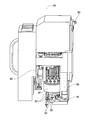
- the supply device 32 is a feeder-type supply device, and includes a plurality of tape feeders 74 that accommodate tape-shaped components 70 (see FIG. 4) on which electronic components P are taped, wound around a reel 72, and the like.
- a feeder main body 77 (see FIG. 4) for feeding out the taped components 70 accommodated in each of the plurality of tape feeders 74 is provided, and the electronic components P are sequentially supplied from the taped components 70 at the supply position.
- the tape feeder 74 of FIG. 4 is a perspective view with a part of the exterior part removed. As shown in FIG.
- the tape feeder 74 has a reel holding unit 76 that holds a reel 72 around which the taped component 70 is wound, and a taped component 70 that is drawn from the reel 72 is extended to the upper end surface.
- a feeder main body 77 is included.
- the feeder main body 77 is fed out in a direction away from the reel 72 on the upper end surface of the feeder main body 77 by rotating a sprocket (not shown) incorporated therein.
- the taped parts 70 are sequentially released by the peeling device (not shown) at the supply position of the tip of the feeder main body 77 and taken out by the suction nozzle 80.
- the tape feeder 74 is detachably attached to the feeder support base 100 provided at the front end portion of the frame portion 20 (see FIG. 1).
- the feeder support base 100 is composed of a slot portion 102 provided on the upper surface of the frame portion 20 and a connection portion 106 erected at an end portion on the rear side (conveying device 26 side) of the slot portion 102.
- the slot portion 102 has a plurality of slots 108 formed along the Y-axis direction.
- the tape feeder 74 is connected to the connecting portion 106 by sliding the lower edge portion of the feeder main body 77 into each of the plurality of slots 108.
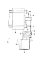
- a connector 114 and a pair of positioning pins 116 are provided at positions where the connector 114 is sandwiched in the vertical direction.
- the connecting portion 106 is formed with a connector 112 to which the connector 114 is connected corresponding to each of the slots 108 and a pair of fitting holes 118 into which the positioning pins 116 are fitted.
- the tape feeder 74 is supplied with power from the feeder support base 100 via the connectors 112 and 114 connected to each other, and also includes necessary control signals (part request signals, part supply completion signals, etc.) and individual tape feeders 74. Management information such as ID is sent.
- the feeder support base 100 is equipped with a disposal box 122 for discarding the electronic component P.
- the disposal box 122 is for collecting the electronic component P that has not been mounted on the circuit board because, for example, it is not attracted to the suction nozzle 80 in a normal posture.
- the disposal box 122 is provided with a connector and a positioning pin (both not shown) for connection to the connecting portion 106.
- the discard box 122 transmits management information such as an ID for identifying each discard box 122 via the connector 112.
- the disposal box 122 may be provided for each type of electronic component P.
- the mounting apparatus 10 of the present embodiment is configured to use optical wireless communication for data transmission between the controller 201 of the mounting apparatus 10 and the movable part (slider 50 and mounting head 28).
- FIG. 5 shows a schematic configuration of the mounting device 10, and each device constituting the mounting device 10 is appropriately omitted.
- the configuration of the communication system illustrated in FIG. 5 is an example, and is appropriately changed according to the type and number of devices included in the mounting device 10.
- the communication system of the present application is a system that can be applied to an automatic machine operating in various production lines in addition to the electronic component mounting apparatus exemplified by the mounting apparatus 10.
- the mounting apparatus 10 includes a controller 201 mainly composed of a computer including a CPU, an optical wireless communication I / F (hereinafter referred to as “optical wireless I / F”) 211, and drive control.
- a board 212 and a short-range wireless communication I / F (hereinafter referred to as “near wireless I / F”) 213 are built in the mounting machine main body 24.
- the optical wireless I / F 211 processes data transmission with the cameras 96 and 98 of the mounting head 28.
- the drive control board 212 is a board that controls input / output of operation commands for the electromagnetic motor 52 of the slider 50 and the electromagnetic motor 54 of the mounting head 28 and information fed back in real time from the electromagnetic motors 52 and 54.
- the drive control board 212 controls the drive circuit 215 connected to each of the electromagnetic motors 52 and 54 by a wired cable to drive the motors 52 and 54.
- the near wireless I / F 213 controls the start of data transmission of a near field wireless communication unit (hereinafter referred to as “communication unit”) 217 connected by a wired cable.
- communication unit a near field wireless communication unit
- the optical wireless I / F 211 is connected to the optical wireless device 221 built in the mounting machine body 24.
- the slider 50 is provided with an optical wireless device 222 that faces the optical wireless device 221.
- the optical wireless device 222 is fixed to the slider 50 so that the optical axis along the Y-axis direction coincides with the optical wireless device 221 of the mounting machine body 24.
- the optical wireless apparatuses 221 and 222 transmit input / output data of the optical wireless I / F 211 by optical wireless communication using, for example, LEDs.
- the optical wireless communication between the optical wireless devices 221 and 222 is transmitted and received as multiplexed data, for example, time division multiplexing (TDM) frame data.
- TDM time division multiplexing
- the optical wireless device 222 is connected to the optical wireless device 224 built in the slider 50.
- the mounting head 28 is provided with an optical wireless device 225 that faces the optical wireless device 224.
- the optical wireless device 225 is fixed to the mounting head 28 so that the optical axis along the X-axis direction coincides with the optical wireless device 224 of the slider 50.
- the optical wireless devices 224 and 225 transmit input / output data of the optical wireless I / F 211 by optical wireless communication.
- the parts camera 96 of the mounting head 28 includes an imaging unit 231, an image processing unit 232, an I / F circuit 233, a memory unit 235, and a short-range wireless communication unit (hereinafter referred to as “communication unit”) 237. .
- the mark camera 98 has the same configuration as that of the parts camera 96, and the internal configuration and detailed description thereof will be omitted as appropriate.
- the imaging unit 231 is an imaging element such as a CMOS sensor or a CCD sensor, for example.
- the imaging unit 231 outputs the captured image data to the image processing unit 232.
- the image processing unit 232 executes various types of image processing for extracting necessary information from the image data input from the imaging unit 231.
- the image processing unit 232 controls the I / F circuit 233 and outputs processing result data to the optical wireless device 225.
- the optical wireless device 225 transmits the processing result to the optical wireless device 221 on the apparatus body side through the optical wireless devices 224 and 222 of the slider 50.
- the image processing unit 232 executes edge detection processing, gamma correction, contour enhancement, and the like as various types of image processing for extracting necessary information. For example, the image processing unit 232 calculates a value for correcting the shift amount of the position of the electronic component P sucked by the suction nozzle 80 from the result of the edge detection process.
- the mark camera 98 has an image processing function for extracting necessary information, detects a reference position mark on the circuit board, and calculates a value for correcting the displacement amount of the circuit board. .
- the parts camera 96 transmits a position correction value to the controller 201 via the optical wireless device 225.
- the controller 201 moves the mounting head 28 onto the circuit board transported by the transport device 26 (see FIG.
- the controller 201 moves or rotates the suction nozzle 80 according to the error of the holding position to correct the holding position, and then mounts the electronic component P on the circuit board.
- the controller 201 holds the suction nozzle 80 by driving and controlling the mounting unit 82 of the mounting head 28 and the servo motor of the unit elevating device 89 (both refer to FIG. 2). Perform position correction.
- This control data is transmitted through optical wireless communication (such as optical wireless device 221).
- the image processing unit 232 compares, for example, the result of the edge detection process with the preset dimensions of each electronic component P to determine whether or not the electronic component P has been normally attracted to the suction nozzle 80.
- the reason why the electronic component P is not normally held by the suction nozzle 80 is that the direction of the electronic component P held by the suction nozzle 80 is incorrect, or the electronic component P is not sucked by the suction nozzle 80.
- the user of the mounting apparatus 10 needs to confirm a captured real image at the time of abnormal suction holding.
- the actual image data obtained by imaging the tip of the suction nozzle 80 has a larger data amount than the processing result data such as the position correction value transmitted in the normal state.
- the mounting apparatus 10 is different from optical wireless communication between the cameras 96 and 98 and the apparatus main body when an abnormality is detected such that the electronic component P is not normally held. Real image data is transmitted through short-range wireless communication.
- the image processing unit 232 executes image processing while executing processing for storing the actual image data input from the imaging unit 231 in the memory unit 235.
- the controller 201 receives processing result data indicating that the electronic component P is not normally held from the image processing unit 232, the controller 201 moves the mounting head 28 onto the disposal box 122 (see FIG. 4) and electronic components. A process of removing P from the suction nozzle 80 and discarding it is executed.
- the mounting head 28 transmits the real image data stored in the memory unit 235 from the communication unit 237 to the communication unit 217 on the apparatus main body side by short-range wireless communication.
- the short-range wireless communication between the communication units 217 and 237 is performed using a communication technique such as TransferJET (registered trademark).
- the communication speed between the communication units 217 and 237 is, for example, 350 Mbps, which is implemented by high-speed communication compared to optical wireless communication.
- the optical wireless communication for transmitting the processing result data (position correction values and the like) of the cameras 96 and 98 at the normal time is a low-speed wireless device (optical wireless device) compared to the communication units 217 and 237 for short-range wireless communication. 221, 222, 224, 225) can be used.
- the communication line during normal operation can be slowed down by using a separate line for large-capacity data transmission that temporarily occurs during the work process when suction retention is abnormal.
- the communication unit 217 on the apparatus main body side is provided in the connection unit 106 of the feeder support base 100.
- the communication unit 217 is provided at a position facing the communication unit 237 of the parts camera 96 when the controller 201 moves the mounting head 28 to the disposal box 122 to discard the electronic component P.
- the mounting head 28 is located close to the connection unit 106 and the disposal box 122 up to a distance of, for example, several centimeters.
- the controller 201 receives, from the near wireless I / F 213, real image data received by the communication unit 217 from the communication unit 237 through short-range wireless communication. Therefore, the controller 201 can perform parallel processing of the operation of discarding the electronic component P and the process of receiving actual image data.
- the controller 201 performs attachment work based on a control program or the like.
- the control program can be easily changed. Further, it is not necessary to secure a separate time for transmission of actual image data, and the influence on production efficiency is extremely small. That is, it is possible to reduce the speed of the communication line at the normal time without lowering the production efficiency when transmitting the image data.
- the controller 201 can perform data transmission by optical wireless communication even when performing short-range wireless communication, the controller 201 can eliminate the influence on the transmission of the processing result data at the normal time by the actual image data transmission. It becomes possible.
- the controller 201 performs processing for transmitting the received real image data to, for example, a control device (not shown) that centrally manages the plurality of mounting machines 16 and storing the actual image data in the external storage device.
- the controller 201 When storing the actual image data, the controller 201 combines other information (for example, time information, the type of the electronic component P, the ID of the disposal box 122, the identification information of the suction nozzle 80, the ID of the circuit board, etc.). Process to send.
- the user can view the actual image data stored in the external storage device on the monitor of the control device or the like when the mounting failure occurs or after the mounting failure occurs.
- the controller 201 may be set to transmit actual image data received through a network to a vendor or the like, for example. Thereby, it becomes possible for a user to deal with a judgment by an expert quickly and accurately.
- the communication units 217 and 237 perform short-range wireless communication in both directions.
- the controller 201 transmits setting data related to image processing of the parts camera 96 corresponding to the changed electronic component P to the communication units 217 and 237.
- This setting data is, for example, a setting value such as the size of a region to be processed by the image processing according to the shape and size of the electronic component P, and processing such as a position correction value output from the image processing unit 232 There is a high possibility that the amount of data will be larger than the result data.
- the controller 201 moves the mounting head 28 to the position of the communication unit 217 of the connection unit 106 (see FIG. 4) in accordance with the processing for changing the tape feeder 74 to be driven.
- the setting data is transmitted to the communication unit 237. This eliminates the need for speeding up the normal communication line in accordance with the transmission of large-capacity data that temporarily occurs during a work process such as when the electronic component P is changed.
- the controller 201 may transmit actual image data from the mounting head 28 side when setting data is transmitted by short-range wireless communication.
- the mounting apparatus 10 includes a mounting camera 28 that includes a parts camera 96 that images the electronic component P sucked by the suction nozzle 80 and a mark camera 98 that images a reference position mark on the circuit board. Each camera 96, 98 has an image processing function for processing captured image data.
- the mounting apparatus 10 includes two types of communication means for transmitting data of the cameras 96 and 98. Each of the cameras 96 and 98 is a controller for processing result data indicating whether or not the electronic component P is normally sucked by the suction nozzle 80 as a result of image processing through optical wireless communication via the optical wireless devices 221, 222, 224, and 225. To 201.
- the controller 201 When the controller 201 detects that the electronic component P is not normally held by the suction nozzle 80 based on the received processing result data, the controller 201 performs control to transmit the actual image data to each of the cameras 96 and 98. Each of the cameras 96 and 98 transmits actual image data to the controller 201 through short-range wireless communication via the communication units 217 and 237.
- the processing result data of the image processing that is normally transmitted in data has a smaller data amount than the actual image data that is necessary when the suction holding is abnormal. For this reason, the optical wireless communication can use a wireless device (such as the optical wireless device 221) that is slower than the short-range wireless communication.
- a large-capacity data transmission that temporarily occurs during a work process such as an abnormality is made a separate line, so that the normal communication line can be slowed down. That is, the transmission efficiency can be improved by optimizing the communication line in accordance with the capacity of the data to be transmitted, and the manufacturing cost can be reduced by using a low-speed and inexpensive wireless communication device.
- the controller 201 performs short-range wireless communication at a timing when it is detected that the electronic component P is not normally held by the suction nozzle 80 based on the processing result data transmitted from the image processing unit 232 of the parts camera 96. By transmitting actual image data, data transmission is efficiently performed.
- the controller 201 transmits the setting data of the parts camera 96 corresponding to the changed electronic component P through the communication units 217 and 237. .
- the high-speed data transmission temporarily generated during the work process such as when the electronic component P is changed is made a separate line, so that the normal communication line can be slowed down.
- the mounting device 10 is provided with a communication unit 217 on the apparatus main body side for short-distance wireless communication at the connection unit 106 to which the disposal box 122 in which the electronic component P with poor mounting is accommodated is connected.
- the communication unit 217 is provided at a position facing the communication unit 237 of the parts camera 96 when the electronic component P is discarded. As a result, the communication units 217 and 237 are more reliable in establishing a communication line when performing short-range wireless communication, and real image data transmission is stably performed.
- the controller 201 performs parallel processing of the operation of discarding the electronic component P and the process of receiving actual image data. As a result, the transmission speed of the normal communication line can be reduced without reducing the production efficiency even when transmitting the actual image data.
- control information for the controller 201 to control the mounting unit 82 of the mounting head 28 and the unit lifting / lowering apparatus 89 is transmitted through optical wireless communication. Optimization is planned.
- optical wireless communication has been described as an example of normal communication means.
- the present application is not limited to this, and wireless communication using various electromagnetic waves other than infrared light and visible light is possible.
- Communication or wired communication (for example, a communication standard based on RS485) may be applied.
- the communication speed of wired communication is lower than that of short-range wireless communication (for example, about 10 Mbps).
- communication cables used for wired communication have structural limitations on the cable jacket and the like when low impedance or impedance matching is required.
- cables that can be used for high-speed communication have lower elasticity.
- the degree of freedom of wiring in the mounting apparatus 10 is restricted. There is a high possibility that the internal signal line is disconnected.
- a low-speed wired cable with high elasticity can be used by optimizing the communication line in accordance with the capacity of data to be transmitted and reducing the speed of the communication line at normal times. As a result, the degree of freedom of wiring of the wired cable connecting the fixed portion and the movable portion is improved, the possibility of disconnection can be reduced, and the reliability of data transmission during normal times can be improved.
- electric field coupling communication may be applied as a normal communication means.
- a flat plate electrode facing the guide rail along the X-axis direction of the slider 50 and the guide block 90 of the mounting head 28 may be provided to transmit data by changing the capacitance.
- the short-range wireless communication in the above embodiment is not limited to TransferJET (registered trademark), but is also an infrared communication standard (Giga-IR), Bluetooth (registered trademark), wireless LAN standard (IEEE802.11), Zigbee (registered trademark).
- a communication means conforming to another communication standard such as a trademark) may be used.
- the communication between the communication units 217 and 237 is not limited to short-range wireless communication, and other wireless communication methods or wired communication may be used. Further, the communication between the communication units 217 and 237 may be a communication at a lower speed than the optical wireless communication (communication between the optical wireless devices 221, 222, 224, and 225).
- the communication units 217 and 237 serving as the second communication unit may be configured to be provided as separate lines other than the optical wireless communication (first communication unit) that transmits the processing result data of the image processing. Even in such a configuration, the communication line can be optimized according to the volume of data to be transmitted, and the transmission efficiency can be improved.
- the electronic component mounting apparatus 10 which mounts the electronic component P on a circuit board was demonstrated in the said embodiment, this application is not limited to this, It applies to the automatic machine etc. which operate
- the present invention may be applied to a communication system in which an assembly part held by a movable part such as a mounting head or an arm is used as a work imaged by the imaging unit 231 and image data and processing result data are transmitted.
- the automatic machine is not limited to one that performs mounting or assembly, and may be applied to a machine tool that performs cutting or the like, for example. In this case, it is good also as a target object which picturizes the work etc. which are cut.
- each mounting machine 16 may be configured to include a plurality of mounting heads 28 and moving devices 30.
- the electronic component mounting device 10 is an example of an electronic component mounting device
- the mounting head 28 is an example of a movable part
- the parts camera 96 and the mark camera 98 are examples of an imaging device
- a disposal box 122 and a connection unit 106 are
- the controller 201 is an example of the control unit
- the optical wireless devices 221, 222, 224, and 225 are examples of the first communication unit
- the communication units 217 and 237 are the first to perform short-range wireless communication.
- the communication unit 217 is an example of the receiving unit
- the electronic component P is an example of the workpiece and the electronic component
- the position correction value is an example of the processing result data.
Abstract
Description
(電子部品装着装置10の構成)
図1は、装着装置10の外装部品の一部を取り除いた斜視図である。装着装置10は、1つのシステムベース12と、システムベース12の上に並んで配列された2つの電子部品装着機(以下、「装着機」と略す場合がある)16とを備え、回路基板に電子部品P(図3参照)を装着する実装装置である。なお、以下の説明では、図1に示すように装着機16が並設される方向をX軸方向、X軸方向に直角で水平方向に沿った方向をY軸方向、X軸方向及びY軸方向に直角な方向を上下方向と称し、説明する。 Embodiments of the present invention will be described below with reference to the drawings. First, an electronic component mounting apparatus (hereinafter sometimes abbreviated as “mounting apparatus”) will be described as an example of an apparatus to which the communication system of the present application is applied.
(Configuration of electronic component mounting apparatus 10)
FIG. 1 is a perspective view in which a part of an exterior component of the mounting
図5に示すように、本実施形態の装着装置10は、装着装置10のコントローラ201と可動部(スライダ50及び装着ヘッド28)との間のデータ伝送に光無線通信を用いる構成となっている。なお、図5は、装着装置10の概略構成を示しており、装着装置10を構成する各装置を適宜省略して示している。また、図5に示す通信システムの構成は一例であり、装着装置10が備える装置の種類や数等に応じて適宜変更される。また、本願の通信システムは、装着装置10に例示される電子部品装着装置の他に、様々な製造ラインにおいて稼働する自動機などに適用可能なシステムである。 (Communication system applied to mounting device 10)
As shown in FIG. 5, the mounting
(1)装着装置10は、吸着ノズル80に吸着された電子部品Pを撮像するパーツカメラ96と回路基板の基準位置マーク等を撮像するマークカメラ98とを装着ヘッド28に備える。各カメラ96,98は、撮像された画像データを処理する画像処理機能を有する。装着装置10は、各カメラ96,98のデータを伝送させる2種類の通信手段を備える。各カメラ96,98は、光無線装置221,222,224,225を介した光無線通信を通じて画像処理の結果として電子部品Pが吸着ノズル80に正常に吸着されたか否かの処理結果データをコントローラ201に送信する。コントローラ201は、受信した処理結果データに基づいて電子部品Pが吸着ノズル80に正常に保持されていないことを検出した場合に、各カメラ96,98に実画像データを伝送させる制御を実行する。各カメラ96,98は、通信部217,237を介した近距離無線通信を通じて実画像データをコントローラ201に送信する。通常時にデータ伝送される画像処理の処理結果データは、吸着保持の異常時に必要な実画像データに比べてデータ量が小さい。このため、光無線通信は、近距離無線通信に比べて低速な無線装置(光無線装置221等)が使用できる。これにより、異常時などの作業工程中に一時的に生じる大容量のデータ伝送を別回線とすることで、通常時の通信回線を低速化できる。つまり、伝送されるデータの容量に応じて通信回線の最適化を図ることによって伝送効率の向上が図れ、ひいては低速で安価な無線通信装置を用いることで製造コストの低減を図ることができる。 As mentioned above, according to this embodiment mentioned above, there exist the following effects.
(1) The mounting
例えば、上記実施形態では、通常時の通信手段として光無線による通信を例に説明したが、本願はこれに限定されるものではなく、赤外線や可視光などの他に様々な電磁波を用いた無線通信、あるいは有線通信(例えば、RS485に準拠した通信規格など)を適用してもよい。この場合においても例えば有線通信の通信速度を近距離無線通信に比べて低速(例えば、10Mbps程度)とすることが好ましい。これにより、伝送されるデータの容量に応じて通信回線の最適化を図ることによって、伝送効率の向上及び製造コストの低減を図ることができる。 In addition, this invention is not limited to said embodiment, It cannot be overemphasized that various improvement and change are possible within the range which does not deviate from the meaning of this invention.
For example, in the above embodiment, optical wireless communication has been described as an example of normal communication means. However, the present application is not limited to this, and wireless communication using various electromagnetic waves other than infrared light and visible light is possible. Communication or wired communication (for example, a communication standard based on RS485) may be applied. Also in this case, for example, it is preferable that the communication speed of wired communication is lower than that of short-range wireless communication (for example, about 10 Mbps). Thereby, by optimizing the communication line according to the capacity of data to be transmitted, it is possible to improve the transmission efficiency and reduce the manufacturing cost.
また、通信部217,237間の通信は、近距離無線通信に限らず、他の無線通信方式や有線通信を用いてもよい。また、通信部217,237間の通信は、光無線通信(光無線装置221,222,224,225間の通信)に比べて低速な通信でもよい。つまり、第2通信手段としての通信部217,237は、画像処理の処理結果データを伝送する光無線通信(第1通信手段)以外に別回線として設けられる構成であればよい。このような構成においても、伝送されるデータの容量に応じて通信回線の最適化を図り、伝送効率の向上が図れる。 The short-range wireless communication in the above embodiment is not limited to TransferJET (registered trademark), but is also an infrared communication standard (Giga-IR), Bluetooth (registered trademark), wireless LAN standard (IEEE802.11), Zigbee (registered trademark). A communication means conforming to another communication standard such as a trademark) may be used.
Further, the communication between the
電子部品装着装置10は、電子部品装着装置の一例として、装着ヘッド28は、可動部の一例として、パーツカメラ96及びマークカメラ98は、撮像装置の一例として、廃棄ボックス122及び接続部106は、収容部の一例として、コントローラ201は、制御部の一例として、光無線装置221,222,224,225は、第1通信手段の一例として、通信部217,237は、近距離無線通信を行う第2通信手段の一例として、通信部217は、受信部の一例として、電子部品Pは、ワーク及び電子部品の一例として、位置補正値は、処理結果データの一例として挙げられる。 The correspondence with the terms in the claims is as follows.
The electronic
Claims (8)
- ワークを保持して移動する可動部と、
前記可動部に対し一体的に設けられ、前記可動部が前記ワークを保持する状態を撮像した画像データから必要情報を抽出する画像処理を施す撮像装置と、
前記撮像装置による画像処理の処理結果データに基づいて前記可動部を駆動させる制御部と、
前記撮像装置から前記制御部に向けて前記処理結果データを伝送する第1通信手段と、
前記第1通信手段以外の第2通信手段と、を備え、
前記制御部は、前記処理結果データに基づいて前記第2通信手段により前記撮像装置から前記画像データを伝送させることを特徴とする通信システム。 A movable part that holds and moves the workpiece;
An imaging device that is provided integrally with the movable part and that performs image processing for extracting necessary information from image data obtained by imaging the state in which the movable part holds the workpiece;
A control unit that drives the movable unit based on processing result data of image processing by the imaging device;
First communication means for transmitting the processing result data from the imaging device to the control unit;
Second communication means other than the first communication means,
The control unit causes the second communication unit to transmit the image data from the imaging device based on the processing result data. - 前記第2通信手段は、前記第1通信手段により伝送される前記処理結果データに比べて大容量のデータを近距離無線通信により伝送する通信装置であることを特徴とする請求項1に記載の通信システム。 2. The communication device according to claim 1, wherein the second communication unit is a communication device that transmits a large amount of data by short-range wireless communication compared to the processing result data transmitted by the first communication unit. Communications system.
- 前記制御部は、前記処理結果データに基づいて前記ワークが前記可動部に正常に保持されていないと判定した場合に、前記第2通信手段により前記画像データを伝送させることを特徴とする請求項1乃至請求項2のいずれかに記載の通信システム。 The control unit causes the second communication unit to transmit the image data when it is determined that the work is not normally held by the movable unit based on the processing result data. The communication system according to claim 1.
- 前記第2通信手段は、双方向の近距離無線通信を行う通信装置であり、
前記制御部は、前記可動部に保持される前記ワークの種類が変更される場合に、変更後のワークに対応した前記撮像装置の画像処理に係る設定データを前記第2通信手段により前記制御部から前記撮像装置に向けて伝送させることを特徴とする請求項1乃至請求項3のいずれかに記載の通信システム。 The second communication means is a communication device that performs bidirectional short-range wireless communication,
When the type of the work held by the movable part is changed, the control unit sends setting data related to image processing of the imaging apparatus corresponding to the changed work by the second communication unit. The communication system according to any one of claims 1 to 3, wherein the transmission is performed toward the imaging apparatus. - 前記制御部が前記処理結果データに基づいて前記ワークが前記可動部に正常に保持されていないと判定した場合に前記ワークを廃棄する収容部を備え、
前記第2通信手段は、前記制御部が前記ワークの廃棄のために前記可動部を前記収容部まで移動させた際に、前記撮像装置に対向する受信部を前記収容部に備えることを特徴とする請求項1乃至請求項4のいずれかに記載の通信システム。 When the control unit determines that the work is not normally held in the movable part based on the processing result data, the control unit includes a storage unit that discards the work.
The second communication unit includes a receiving unit facing the imaging device when the control unit moves the movable unit to the storage unit for discarding the workpiece. The communication system according to any one of claims 1 to 4. - 前記制御部は、前記可動部による前記ワークを破棄する処理と、前記第2通信手段による前記撮像装置から前記受信部に向けた前記画像データを伝送する処理とを並列的に実行することを特徴とする請求項5に記載の通信システム。 The control unit performs in parallel a process of discarding the workpiece by the movable part and a process of transmitting the image data from the imaging device to the receiving unit by the second communication unit. The communication system according to claim 5.
- 前記第1通信手段は、多重化された光無線の双方向通信を行う通信装置であり、
前記制御部は、前記可動部を駆動する制御データを前記第1通信手段により伝送させることを特徴とする請求項1乃至請求項6のいずれかに記載の通信システム。 The first communication means is a communication device that performs multiplexed optical wireless bidirectional communication,
The communication system according to claim 1, wherein the control unit transmits control data for driving the movable unit by the first communication unit. - 前記可動部により前記ワークとして保持される電子部品の回路基板への装着作業に係るデータの伝送を請求項1乃至請求項7のいずれかに記載の通信システムにより伝送する電子部品装着装置。 8. An electronic component mounting apparatus that transmits data related to mounting work of an electronic component held as the workpiece by the movable portion on a circuit board by the communication system according to claim 1.
Priority Applications (4)
| Application Number | Priority Date | Filing Date | Title |
|---|---|---|---|
| CN201380073796.7A CN105075421B (en) | 2013-02-26 | 2013-02-26 | Communication system and electronic element installation device |
| JP2015502592A JP6162211B2 (en) | 2013-02-26 | 2013-02-26 | Communication system and electronic component mounting apparatus |
| EP13876183.8A EP2964007B1 (en) | 2013-02-26 | 2013-02-26 | Communication system and electronic component mounting device |
| PCT/JP2013/054851 WO2014132324A1 (en) | 2013-02-26 | 2013-02-26 | Communication system and electronic component mounting device |
Applications Claiming Priority (1)
| Application Number | Priority Date | Filing Date | Title |
|---|---|---|---|
| PCT/JP2013/054851 WO2014132324A1 (en) | 2013-02-26 | 2013-02-26 | Communication system and electronic component mounting device |
Publications (1)
| Publication Number | Publication Date |
|---|---|
| WO2014132324A1 true WO2014132324A1 (en) | 2014-09-04 |
Family
ID=51427629
Family Applications (1)
| Application Number | Title | Priority Date | Filing Date |
|---|---|---|---|
| PCT/JP2013/054851 WO2014132324A1 (en) | 2013-02-26 | 2013-02-26 | Communication system and electronic component mounting device |
Country Status (4)
| Country | Link |
|---|---|
| EP (1) | EP2964007B1 (en) |
| JP (1) | JP6162211B2 (en) |
| CN (1) | CN105075421B (en) |
| WO (1) | WO2014132324A1 (en) |
Cited By (2)
| Publication number | Priority date | Publication date | Assignee | Title |
|---|---|---|---|---|
| JPWO2016088214A1 (en) * | 2014-12-03 | 2017-09-07 | 富士機械製造株式会社 | Multiplexed communication system and work machine |
| WO2020100254A1 (en) * | 2018-11-15 | 2020-05-22 | 株式会社Fuji | Work machine and work system |
Families Citing this family (4)
| Publication number | Priority date | Publication date | Assignee | Title |
|---|---|---|---|---|
| US11751373B2 (en) * | 2017-12-28 | 2023-09-05 | Fuji Corporation | Tracing device |
| JP7149456B2 (en) * | 2018-05-30 | 2022-10-07 | パナソニックIpマネジメント株式会社 | Component mounter |
| JP6792686B1 (en) * | 2019-09-20 | 2020-11-25 | ソフトバンク株式会社 | Mobiles, programs, and control methods |
| CN113453439B (en) * | 2021-07-15 | 2022-11-11 | 吉安满坤科技股份有限公司 | Sensing control Touch technology printed circuit board and preparation method thereof |
Citations (5)
| Publication number | Priority date | Publication date | Assignee | Title |
|---|---|---|---|---|
| JPH06164192A (en) * | 1992-11-19 | 1994-06-10 | Matsushita Electric Ind Co Ltd | Component mounting device |
| JP2006279927A (en) * | 2005-03-01 | 2006-10-12 | Omron Corp | Supervisory and control apparatus, monitoring system, monitoring method, program and recording medium |
| JP2009218933A (en) | 2008-03-11 | 2009-09-24 | Seiko Epson Corp | Smart camera and robot vision system |
| JP2011124605A (en) * | 2011-02-10 | 2011-06-23 | Hitachi High-Tech Instruments Co Ltd | Electronic component mounting device |
| JP2013026439A (en) * | 2011-07-21 | 2013-02-04 | Fuji Mach Mfg Co Ltd | Component mounting line |
Family Cites Families (7)
| Publication number | Priority date | Publication date | Assignee | Title |
|---|---|---|---|---|
| JPH08316695A (en) * | 1995-05-12 | 1996-11-29 | Toshiba Corp | Component mounting apparatus |
| JP2006042210A (en) * | 2004-07-29 | 2006-02-09 | Victor Co Of Japan Ltd | Optical radio receiver |
| JP2006054550A (en) * | 2004-08-10 | 2006-02-23 | Victor Co Of Japan Ltd | Transmission system |
| CN1829317A (en) * | 2005-03-01 | 2006-09-06 | 欧姆龙株式会社 | Monitoring control apparatus, monitoring system, monitoring method, wireless communication apparatus and wireless communication system |
| DE102006027662A1 (en) * | 2006-06-14 | 2007-12-20 | Siemens Ag | Method for data transmission between a placement head control device and a central control device in a placement machine, placement machine, placement head, transmitter-side transmission device and system of transmitter-side and receiver-side transmission device |
| JP4674220B2 (en) * | 2007-03-05 | 2011-04-20 | ヤマハ発動機株式会社 | Component transfer device, surface mounter, and electronic component inspection device |
| JP4998485B2 (en) * | 2009-01-23 | 2012-08-15 | パナソニック株式会社 | Component mounting line and component mounting method |
-
2013
- 2013-02-26 EP EP13876183.8A patent/EP2964007B1/en active Active
- 2013-02-26 JP JP2015502592A patent/JP6162211B2/en active Active
- 2013-02-26 CN CN201380073796.7A patent/CN105075421B/en active Active
- 2013-02-26 WO PCT/JP2013/054851 patent/WO2014132324A1/en active Application Filing
Patent Citations (5)
| Publication number | Priority date | Publication date | Assignee | Title |
|---|---|---|---|---|
| JPH06164192A (en) * | 1992-11-19 | 1994-06-10 | Matsushita Electric Ind Co Ltd | Component mounting device |
| JP2006279927A (en) * | 2005-03-01 | 2006-10-12 | Omron Corp | Supervisory and control apparatus, monitoring system, monitoring method, program and recording medium |
| JP2009218933A (en) | 2008-03-11 | 2009-09-24 | Seiko Epson Corp | Smart camera and robot vision system |
| JP2011124605A (en) * | 2011-02-10 | 2011-06-23 | Hitachi High-Tech Instruments Co Ltd | Electronic component mounting device |
| JP2013026439A (en) * | 2011-07-21 | 2013-02-04 | Fuji Mach Mfg Co Ltd | Component mounting line |
Cited By (2)
| Publication number | Priority date | Publication date | Assignee | Title |
|---|---|---|---|---|
| JPWO2016088214A1 (en) * | 2014-12-03 | 2017-09-07 | 富士機械製造株式会社 | Multiplexed communication system and work machine |
| WO2020100254A1 (en) * | 2018-11-15 | 2020-05-22 | 株式会社Fuji | Work machine and work system |
Also Published As
| Publication number | Publication date |
|---|---|
| EP2964007A1 (en) | 2016-01-06 |
| CN105075421B (en) | 2018-09-18 |
| EP2964007B1 (en) | 2020-07-22 |
| JP6162211B2 (en) | 2017-07-12 |
| CN105075421A (en) | 2015-11-18 |
| JPWO2014132324A1 (en) | 2017-02-02 |
| EP2964007A4 (en) | 2016-10-19 |
Similar Documents
| Publication | Publication Date | Title |
|---|---|---|
| JP6162211B2 (en) | Communication system and electronic component mounting apparatus | |
| US10492350B2 (en) | Electronic component mounting method and electronic component mounting apparatus | |
| JP6293899B2 (en) | Mounting device | |
| EP3197255B1 (en) | Component mounting device | |
| JP2013051240A (en) | Component supply method and component mounting device | |
| JP2011228583A (en) | Imaging determining method for electronic component and component mounter | |
| US10039218B2 (en) | Electronic circuit component mounting system | |
| JP6828223B2 (en) | Mounting device | |
| JP2021158372A (en) | Component mounting machine | |
| JP6356222B2 (en) | Component mounting device | |
| WO2015097865A1 (en) | Component mounting device and component mounting method | |
| CN108293322B (en) | Working device | |
| JP6475165B2 (en) | Mounting device | |
| JP2009212373A (en) | Component mounting apparatus | |
| US11778798B2 (en) | Information processing device, work system, and determination method | |
| JP6956861B2 (en) | Work equipment and imaging control method for work equipment | |
| JP5506583B2 (en) | Component mounting method | |
| JP2022107877A (en) | Component imaging apparatus and component mounting device | |
| JP6905976B2 (en) | Anti-board work machine | |
| WO2014128884A1 (en) | Communication system and electronic component mounting device | |
| JP4805084B2 (en) | Imaging control apparatus and surface mounter | |
| JP7149456B2 (en) | Component mounter | |
| JP7330075B2 (en) | Component placement system | |
| WO2013084330A1 (en) | Optical wireless system, imaging device, and control device | |
| JP2022088797A (en) | Mounting method and mounting device |
Legal Events
| Date | Code | Title | Description |
|---|---|---|---|
| WWE | Wipo information: entry into national phase |
Ref document number: 201380073796.7 Country of ref document: CN |
|
| 121 | Ep: the epo has been informed by wipo that ep was designated in this application |
Ref document number: 13876183 Country of ref document: EP Kind code of ref document: A1 |
|
| ENP | Entry into the national phase |
Ref document number: 2015502592 Country of ref document: JP Kind code of ref document: A |
|
| WWE | Wipo information: entry into national phase |
Ref document number: 2013876183 Country of ref document: EP |
|
| NENP | Non-entry into the national phase |
Ref country code: DE |