JP4805084B2 - Imaging control apparatus and surface mounter - Google Patents
Imaging control apparatus and surface mounter Download PDFInfo
- Publication number
- JP4805084B2 JP4805084B2 JP2006272031A JP2006272031A JP4805084B2 JP 4805084 B2 JP4805084 B2 JP 4805084B2 JP 2006272031 A JP2006272031 A JP 2006272031A JP 2006272031 A JP2006272031 A JP 2006272031A JP 4805084 B2 JP4805084 B2 JP 4805084B2
- Authority
- JP
- Japan
- Prior art keywords
- imaging
- signal
- image
- processing device
- signal line
- Prior art date
- Legal status (The legal status is an assumption and is not a legal conclusion. Google has not performed a legal analysis and makes no representation as to the accuracy of the status listed.)
- Active
Links
- 238000003384 imaging method Methods 0.000 title claims description 179
- 238000012545 processing Methods 0.000 claims description 110
- 238000004891 communication Methods 0.000 claims description 71
- 239000002131 composite material Substances 0.000 claims description 28
- 239000000758 substrate Substances 0.000 claims description 23
- 238000010586 diagram Methods 0.000 description 6
- 238000000034 method Methods 0.000 description 5
- 238000012544 monitoring process Methods 0.000 description 4
- 230000005540 biological transmission Effects 0.000 description 2
- 238000013461 design Methods 0.000 description 2
- 238000007493 shaping process Methods 0.000 description 2
- 239000003990 capacitor Substances 0.000 description 1
- 238000011982 device technology Methods 0.000 description 1
- 238000005286 illumination Methods 0.000 description 1
- 230000002093 peripheral effect Effects 0.000 description 1
- 238000001179 sorption measurement Methods 0.000 description 1
- 230000001360 synchronised effect Effects 0.000 description 1
Images


Landscapes
- Closed-Circuit Television Systems (AREA)
- Studio Devices (AREA)
Description
本発明は、例えば産業用の監視カメラなど複数の撮像手段を制御する撮像制御装置と、このような撮像制御装置を備えた表面実装機に関するものである。 The present invention relates to an image pickup control apparatus that controls a plurality of image pickup means such as industrial surveillance cameras, and a surface mounter including such an image pickup control apparatus.
一般に、電子部品を基板上に実装する表面実装機には、吸着ノズルに吸着された電子部品の吸着状態を認識するためのカメラや基板に付されたマークを認識するためのカメラなどの複数の撮像手段と、このような撮像手段が発信した画像信号を認識処理する画像処理装置とが設けられている。 Generally, a surface mounter that mounts electronic components on a substrate includes a plurality of cameras, such as a camera for recognizing the suction state of an electronic component sucked by a suction nozzle and a camera for recognizing a mark attached to the substrate. An imaging means and an image processing apparatus for recognizing and processing an image signal transmitted by such an imaging means are provided.
そして、これら複数の撮像手段と画像処理装置との間には、画像信号を画像処理装置に伝達する画像信号線と、画像処理装置が発信した撮像手段の駆動を制御する制御信号を撮像手段に伝達する制御信号線とが設けられ、これら画像信号線と、制御信号線とを適宜切り替えて、任意の撮像手段の画像信号を1つの画像処理装置で認識処理できるように構成されている。 An image signal line for transmitting an image signal to the image processing apparatus and a control signal for controlling driving of the imaging means transmitted by the image processing apparatus are provided between the plurality of imaging means and the image processing apparatus. A control signal line for transmission is provided, and the image signal line and the control signal line are appropriately switched so that an image signal of an arbitrary imaging unit can be recognized and processed by one image processing apparatus.
例えば、特許文献1には、クロック信号、水平および垂直同期パルス、各種電源を切り替える信号切り替え部を備えた監視カメラ切り替え装置の技術が開示されている。
しかしながら、上述の監視カメラ切り替え装置の技術では、クロック信号、水平および垂直同期パルス、各種電源等を制御するための信号制御ユニットのほかに、監視カメラの切り替えを行うための信号切り替えユニットおよび切り換え用信号線等を別途設ける必要がある。その結果、監視カメラと制御装置のためのシステムが高価になるという問題があった。 However, in the above-described surveillance camera switching device technology, in addition to the signal control unit for controlling the clock signal, horizontal and vertical synchronization pulses, various power sources, etc., the signal switching unit for switching the surveillance camera and the switching It is necessary to provide signal lines separately. As a result, there is a problem that the system for the monitoring camera and the control device becomes expensive.
本発明は上記不具合に鑑みてなされたものであり、各監視カメラの切り換えや設定変更を一つの撮像制御装置によって行うことができ、簡単な構成で多様な撮像手段の切り替えと制御ができる撮像制御装置およびこのような撮像制御装置を備えた表面実装機を提供することを課題としている。 The present invention has been made in view of the above-described problems, and can perform switching and setting change of each monitoring camera by a single imaging control device, and imaging control capable of switching and controlling various imaging means with a simple configuration. It is an object of the present invention to provide a device and a surface mounter including such an imaging control device.
上記課題を解決するための本発明にかかる撮像制御装置は、複数の撮像手段と画像処理装置との間に設けられる撮像制御装置であって、撮像手段が発信した画像にかかる撮像信号を画像処理装置に伝達する各撮像手段ごとの撮像信号線と、撮像手段の駆動を制御する制御信号を撮像手段に伝達する各撮像手段ごとの制御信号線と、各撮像信号線および各制御信号線を介して各撮像手段に接続されるとともに各信号線を介して画像処理装置に接続される信号処理装置と、複数の撮像手段と信号処理装置と画像処理装置とにわたって設けられ、撮像手段と画像処理装置との間で送受信するシリアル通信信号を相互に伝達するシリアル通信線とを備え、上記信号処理装置は、いずれかの撮像手段からの撮像信号を選択的に画像処理装置に送るように撮像信号線を切り替える撮像信号線切り替え回路と、画像処理装置が発信した制御信号を選択的にいずれかの撮像手段に送るように制御信号線を切り替える制御信号線切り替え回路と、上記シリアル通信線により複数の撮像手段と画像処理装置との間で伝達されるシリアル通信信号に含まれる切り替え情報に応じて、上記撮像信号線切り替え回路および制御信号線切り替え回路における切り替えを制御する演算回路とを含んでいることを特徴としている。 An imaging control apparatus according to the present invention for solving the above-described problems is an imaging control apparatus provided between a plurality of imaging means and an image processing apparatus, and performs image processing on an imaging signal relating to an image transmitted by the imaging means. An imaging signal line for each imaging means to be transmitted to the apparatus, a control signal line for each imaging means to transmit a control signal for controlling driving of the imaging means to the imaging means, and each imaging signal line and each control signal line A signal processing device connected to each imaging means and connected to the image processing device via each signal line, a plurality of imaging means, the signal processing device, and the image processing device. A serial communication line for transmitting and receiving serial communication signals to and from each other, and the signal processing device selectively sends an imaging signal from any imaging means to the image processing device An imaging signal line switching circuit for switching an image signal line, a control signal line switching circuit for switching a control signal line so as to selectively send a control signal transmitted from the image processing apparatus to any imaging means, and the serial communication line An arithmetic circuit that controls switching in the imaging signal line switching circuit and the control signal line switching circuit in accordance with switching information included in a serial communication signal transmitted between the plurality of imaging units and the image processing apparatus. It is characterized by being.
本発明によれば、複数の撮像手段と画像処理装置との間に設けられたシリアル通信線が、撮像手段と画像処理装置との間で送受信するシリアル通信信号を相互に伝達し、演算回路が、このシリアル通信信号に含まれる切り替え情報に応じて、複合切り替え回路の撮像信号線切り替え回路と、制御信号線切り替え回路とにおける、それぞれの信号線の選択的な切り替えを制御する。その結果、シリアル通信信号に含まれる切り替え情報を介して、ゲインや露光時間などの、各監視カメラの設定変更についても撮像制御装置側から切り替えたり、変更したりすることができるようになるなど、一つの撮像制御装置から多様な撮像手段の切り替えと制御ができるようになる。 According to the present invention, the serial communication lines provided between the plurality of imaging means and the image processing apparatus mutually transmit serial communication signals transmitted and received between the imaging means and the image processing apparatus, and the arithmetic circuit In accordance with the switching information included in the serial communication signal, the selective switching of each signal line in the imaging signal line switching circuit and the control signal line switching circuit of the composite switching circuit is controlled. As a result, via the switching information included in the serial communication signal, the setting change of each surveillance camera, such as gain and exposure time, can also be switched or changed from the imaging control device side, etc. A variety of imaging means can be switched and controlled from one imaging control device.
そして、シリアル通信を利用して切り替え情報を与えるようにしているため、信号切り替えのための制御ユニットや配線を別途設ける必要がない。 Since switching information is given using serial communication, it is not necessary to separately provide a control unit and wiring for signal switching.
ここで、上記撮像手段と信号処理装置との間において上記撮像信号と、制御信号と、シリアル通信信号とは、撮像手段および信号処理装置の両方もしくはいずれか一方に対して装脱可能な、一体となった撮像手段側複合通信ケーブルに備えられた撮像信号線と、制御信号線と、シリアル通信線とを介してそれぞれの信号が撮像手段と信号処理装置との間で授受されるものであることが好ましい。 Here, the image pickup signal, the control signal, and the serial communication signal between the image pickup means and the signal processing device can be attached to and / or removed from the image pickup means and / or the signal processing device. Each signal is exchanged between the image pickup means and the signal processing device via the image pickup signal line, the control signal line, and the serial communication line provided in the image pickup means side composite communication cable. It is preferable.
このようにすれば、撮像手段や信号処理装置に装脱可能な、撮像手段側複合通信ケーブルを介してそれぞれの信号が授受されるので、撮像手段と信号処理装置との間の信号線にかかる配線とその取り扱いが容易になる。 In this way, since each signal is exchanged via the imaging means side composite communication cable that can be attached to and detached from the imaging means and the signal processing apparatus, the signal lines between the imaging means and the signal processing apparatus are applied. Wiring and its handling become easy.
また、上記信号処理装置と画像処理装置との間において上記撮像信号と、制御信号と、シリアル通信信号とは、信号処理装置および画像処理装置の両方もしくはいずれか一方に対して装脱可能な、画像処理装置側複合通信ケーブルに備えられた撮像信号線と、制御信号線と、シリアル通信線とを介してそれぞれの信号が撮像手段と信号処理装置との間で授受されるものであることが好ましい。 In addition, the imaging signal, the control signal, and the serial communication signal between the signal processing device and the image processing device can be attached to and detached from either or both of the signal processing device and the image processing device. Each signal is exchanged between the imaging means and the signal processing device via the imaging signal line, the control signal line, and the serial communication line provided in the composite communication cable on the image processing apparatus side. preferable.
このようにすれば、信号処理装置や画像処理装置に装脱可能な、画像処理装置側複合通信ケーブルを介してそれぞれの信号が授受されるので、信号処理装置と画像処理装置との間の信号線にかかる配線とその取り扱いが容易になる。 In this way, each signal is exchanged via the image processing apparatus-side composite communication cable that can be attached to and detached from the signal processing apparatus or the image processing apparatus, so that the signal between the signal processing apparatus and the image processing apparatus Wiring and handling of the wires are easy.
そして、上記撮像信号は、撮像手段が撮像した画像の画像信号と撮像手段が採用しているクロック信号とを含み、上記撮像信号線は、この画像信号を伝達する画像信号線とクロック信号を伝達するクロック信号線とを備え、上記撮像信号線切り替え回路は、この画像信号線を選択的に切り替える画像信号線切り替え回路とクロック信号線を選択的に切り替えるクロック信号線切り替え回路とを備えていることが好ましい。 The image pickup signal includes an image signal of an image picked up by the image pickup means and a clock signal adopted by the image pickup means, and the image pickup signal line transmits an image signal line for transmitting the image signal and a clock signal. The imaging signal line switching circuit includes an image signal line switching circuit that selectively switches the image signal line and a clock signal line switching circuit that selectively switches the clock signal line. Is preferred.
このようにすれば、画像信号線切り替え回路が、画像信号線を選択的に切り替えるとともに、クロック信号線切り替え回路が、クロック信号線を選択的に切り替えるので、画像信号としてデジタルな画像信号を複数の撮像手段と画像処理装置との間で切り替えることができるようになる。 According to this configuration, the image signal line switching circuit selectively switches the image signal line, and the clock signal line switching circuit selectively switches the clock signal line. It becomes possible to switch between the imaging means and the image processing apparatus.
また、上記シリアル通信信号は、撮像手段の状態を報告するレポート情報および撮像手段の設定変更にかかる設定コマンド情報を含んでいることが好ましい。 The serial communication signal preferably includes report information for reporting the state of the imaging means and setting command information for changing the setting of the imaging means.
このようにすれば、撮像手段の切り替えを行う際に、選択した撮像手段の状態にかかるレポート情報を入手したり、この撮像手段の設定変更を行ったりすることができるようになる。 In this way, when the image pickup means is switched, report information relating to the state of the selected image pickup means can be obtained or the setting of the image pickup means can be changed.
また、上記課題を解決するための本発明にかかる表面実装機は、吸着ノズルを備えた移動可能な実装用ヘッドの前記吸着ノズルにより部品供給部から電子部品を吸着するとともに、この吸着ノズルに吸着された電子部品の吸着状態を画像認識手段により画像認識してからこの電子部品を基板上に実装する表面実装機であって、上記画像認識手段に設けられた撮像手段を含む複数の撮像手段と、この撮像手段が撮像した画像の画像処理を行う画像処理装置と、上記の本発明にかかる撮像制御装置を備えていることを特徴としている。 Further, a surface mounting machine according to the present invention for solving the above-described problems is to suck an electronic component from a component supply unit by the suction nozzle of a movable mounting head provided with a suction nozzle and to suck the suction component to the suction nozzle. A surface mounter that mounts the electronic component on a substrate after the image recognition means recognizes the picked-up state of the electronic component, and a plurality of image pickup means including the image pickup means provided in the image recognition means; The image processing apparatus includes an image processing apparatus that performs image processing on an image captured by the imaging unit, and the above-described imaging control apparatus according to the present invention.
本発明にかかる表面実装機によれば、表面実装機の画像認識手段が上記の本発明にかかる撮像制御装置を備えているので、多様な撮像手段の切り替えと制御がシリアル通信信号に含まれる切り替え情報を介して可能になる。 According to the surface mounter of the present invention, since the image recognition unit of the surface mounter includes the above-described image pickup control apparatus according to the present invention, the switching and control of various image pickup means are included in the serial communication signal. Made possible through information.
以上説明したように、本発明にかかる撮像制御装置と、表面実装機とによれば、シリアル通信信号に含まれる切り替え情報を介して一つの撮像制御装置から多様な撮像手段の切り替えと制御が可能になる。 As described above, according to the imaging control device and the surface mounter according to the present invention, various imaging means can be switched and controlled from one imaging control device via the switching information included in the serial communication signal. become.
そして、シリアル通信を利用して切り替え情報を与えるようにしているため、信号切り替えのための制御ユニットや配線を別途設ける必要がない。 Since switching information is given using serial communication, it is not necessary to separately provide a control unit and wiring for signal switching.
以下、添付図面を参照しながら本発明の好ましい実施の一形態について詳述する。図1は本発明の実施の形態に係る撮像制御装置30を備えた表面実装機1の構成を示す平面図であり、図2は、表面実装機1のヘッドユニット7の周辺の構成を示す側面図である。
Hereinafter, a preferred embodiment of the present invention will be described in detail with reference to the accompanying drawings. FIG. 1 is a plan view illustrating a configuration of a surface mounter 1 including an
図1と図2とに示すように、本発明の実施の形態に係る表面実装機1は、電子部品を基板2に実装する装置であって、基台3上に配置されて基板2を搬送する基板搬送手段4と、この基板搬送手段4の両側に配置され、複数の電子部品を供給する部品供給部5と、この部品供給部5から電子部品を吸着することが可能な吸着用ノズルを有する実装用ヘッド6を担持して部品供給部5と基板2との間を移動可能なヘッドユニット7と、実装用ヘッド6の吸着ノズルに吸着された電子部品について吸着状態の認識などを行う画像認識手段8(図3)とを備えている。
As shown in FIGS. 1 and 2, a surface mounter 1 according to an embodiment of the present invention is an apparatus for mounting electronic components on a substrate 2, and is disposed on a
上記基板搬送手段4は、基台3上において基板2を図1の右側から左側へ搬送する一対のコンベア4a、4aを有しており、このコンベア4a、4aにより搬入された基板2は、所定の実装作業位置(同図に示す基板2の位置)で一旦停止させられ、ここで電子部品が基板2に実装される。
The substrate transport means 4 has a pair of
上記部品供給部5は、基板搬送手段4の両側に配列された多数のテープフィーダ5aを備えている。このテープフィーダ5aは、詳しくは図示しないが、各々IC、トランジスタ、コンデンサ等の小片状のチップ電子部品を所定間隔おきに収納、保持したテープが巻回されたリールを有しており、このリールから電子部品を間欠的に繰り出すように構成されている。
The
上記実装用ヘッド6は、この部品供給部5のリールから間欠的に繰り出される電子部品を吸着ノズルにより吸着保持するものであり、図略の負圧発生装置に接続されることにより、ノズル先端に負圧状態を発生させ、この負圧吸着力により、電子部品を着脱可能に吸着保持し得るようになっている。
The
また上記吸着ノズルは、それぞれ、ヘッドユニット7に対して図略のノズル昇降駆動手段により昇降(Z軸方向の移動)が可能に、かつ図略のノズル回転駆動手段によりノズル中心軸回りの回転(R軸回りの回転)が可能に構成されている。
The suction nozzles can be moved up and down (moved in the Z-axis direction) with respect to the
ここで、ノズル昇降駆動手段は、吸着もしくは装着を行う時の下降位置と、搬送や撮像を行う時の上昇位置との間で吸着ノズル吸着ノズルを昇降させるものであり、ノズル回転駆動手段は、吸着ノズルを必要に応じて回転させて、電子部品の姿勢を調整するものである。これらノズル昇降駆動手段とノズル回転駆動手段は、それぞれサーボモータと所定の動力伝達機構で構成されている。 Here, the nozzle raising / lowering driving means raises and lowers the suction nozzle suction nozzle between a lowered position when performing suction or mounting and an elevated position when performing conveyance or imaging. The suction nozzle is rotated as necessary to adjust the posture of the electronic component. These nozzle lifting and lowering driving means and nozzle rotation driving means are each constituted by a servo motor and a predetermined power transmission mechanism.
上記ヘッドユニット7は、本実施形態では、6本の実装用ヘッド6がX軸方向(基板搬送手段4の搬送方向)に等間隔で一列に並べられた状態で搭載され、これらの実装用ヘッド6で吸着された複数の電子部品を部品供給部5と基板2との間で搬送し、電子部品を基板2に一つ一つ実装する。そのため、このヘッドユニット7は、基台3の所定範囲にわたりX軸方向及びY軸方向(X軸方向と直交する方向)に移動可能となっている。
In the present embodiment, the
すなわち、ヘッドユニット7は、X軸方向に延びる実装用ヘッド支持部材7aに対してX軸に沿って移動可能に支持されている。また、実装用ヘッド支持部材7aは、両端部がY軸方向の固定レール9に支持され、この固定レール9に沿ってY軸方向に移動可能になっている。そして、このヘッドユニット7は、X軸サーボモータ11によりボールねじ12を介してX軸方向に駆動され、実装用ヘッド支持部材7aは、Y軸サーボモータ13によりボールねじ14を介してY軸方向へ駆動される。
That is, the
上記画像認識手段8(図3)は、複数の撮像手段15、16として、本実施形態では、ヘッドユニット7に設けられた2つのマークカメラ15(15a、15b)と、1つのサイドビューカメラ16とを備えている。また、この画像認識手段8は、これらの撮像手段15、16が撮像した画像の画像処理を行う画像処理装置23(図3)と、本発明にかかる撮像制御装置30(図3)を備えている。
In the present embodiment, the image recognition unit 8 (FIG. 3) includes two mark cameras 15 (15a and 15b) provided in the
マークカメラ15(15a、15b)は、基板2に設けられたフィデューシャルマーク3a,3b)を認識することにより、基板2の位置を認識するためのカメラであり、撮像方向を下向きにした状態でヘッドユニット7に組付けられている。基板2が実装作業位置に搬入されると、このマークカメラ15による撮像に基づきフィデューシャルマーク3a,3bが画像認識され、装置本体に対する基板2の相対的な位置関係が調べられるようになっている。
The mark camera 15 (15a, 15b) is a camera for recognizing the position of the substrate 2 by recognizing the
サイドビューカメラ16は、吸着ノズルによる電子部品の吸着状態を側方から画像認識するためのカメラであり、撮像方向を横向きにした状態で実装用ヘッド支持部材7aに固定されている。電子部品が、各部品供給部5において吸着ノズルに吸着されると、このサイドビューカメラ16による撮像に基づき、各部品供給部5から基板2に移送される間に吸着ノズルの横方から電子部品が画像認識されるようになっている。
The
その他、本実施形態では、部品認識カメラ17が設けられている。この部品認識カメラ17は、吸着ノズルによる電子部品の吸着状態を画像認識するためのカメラであり、撮像方向を上向きにした状態で基台1上に固定されている。電子部品が、各部品供給部5において吸着ノズルに吸着されると、この部品認識カメラ17による撮像に基づき、各部品供給部5から基板2に移送される間に吸着ノズルの下方から電子部品が画像認識され、吸着ノズルに対する電子部品の吸着状態が調べられるようになっている。
In addition, in this embodiment, a
また、これらのマークカメラ15とサイドビューカメラ16と部品認識カメラ17とは、それぞれ照明装置を一体に備えている。
The
なお、本実施形態では、マークカメラ15とサイドビューカメラ16の制御にかかる撮像制御装置30について説明し、部品認識カメラ17の制御については、説明を省略するものとする。
In the present embodiment, the
次に、図3〜図5を参照して表面実装機1の制御装置20について説明する。図3は、表面実装機1の制御装置20の概略の構成を示すブロック図である。
Next, the
図3に示すように、表面実装機1の制御装置20は、その機能構成として主制御装置21、軸制御装置22、画像処理装置23を備えている。
As shown in FIG. 3, the
主制御装置21は、実装機の動作を統括的に制御するもので、論理演算を実行する周知のCPU、そのCPUを制御する種々のプログラムなどを予め記憶するROMおよび装置動作中に種々のデータを一時的に記憶するRAM等から構成される。
The
この主制御装置21は、図略の記憶部に予め記憶されているプログラムに従ってヘッドユニット7等を作動すべく軸制御装置22を介して各サーボモータ24を駆動制御する。なお各サーボモータ24には、それぞれエンコーダ25が設けられており、これにより各部の移動位置が検出される。
The
また、この主制御装置21は、画像処理装置23と本発明にかかる撮像制御装置30とを介してマークカメラ15およびサイドビューカメラ16を駆動制御するように構成されている。
The
ここで、図4は、本発明の実施の形態に係る撮像制御装置30の概略の構成を示すブロック図である。
Here, FIG. 4 is a block diagram showing a schematic configuration of the
図4に示すように、本発明の実施の形態に係る撮像制御装置30は、撮像手段15、16(マークカメラ15a、15bおよびサイドビューカメラ16)と画像処理装置23との間に設けられた信号処理装置30aを備え、この信号処理装置30aは、後記撮像信号線35および制御信号線36などの通信線を含む撮像手段側複合通信ケーブル37を介して各撮像手段15、16に接続されるとともに、信号線35、36などの通信線を含む画像処理装置側複合通信ケーブル38を介して制御装置20の画像処理装置23に接続されている。また、上記信号処理装置30aは、複合切り替え回路31と、シリアル通信線32と、複合切り替え回路31の信号線の選択的な切り替えを制御する演算回路33と、波形整形回路34とを備えている。
As shown in FIG. 4, the
上記複合切り替え回路31は、複数の撮像手段15、16(マークカメラ15およびサイドビューカメラ16)と画像処理装置23との間に設けられた撮像信号線切り替え回路31aと制御信号線切り替え回路31bとを有している。
The
撮像信号線切り替え回路31aは、いずれかの撮像手段15、16からの撮像信号を選択的に制御装置20の画像処理装置23に送るため、撮像手段15、16が発信した画像にかかる撮像信号を伝達する撮像信号線35を切り替える回路である。
The imaging signal
撮像信号は、撮像手段15、16が撮像した画像の画像信号と撮像手段15、16が採用しているクロック信号とを含み、撮像信号線35は、この画像信号を伝達する画像信号線35aとクロック信号を伝達するクロック信号線35bとを備え、撮像信号線切り替え回路31aは、この画像信号線35aを選択的に切り替える画像信号線切り替え回路35cとクロック信号線35bを選択的に切り替えるクロック信号線切り替え回路35dとを備えている。
The imaging signal includes an image signal of an image taken by the imaging means 15 and 16 and a clock signal adopted by the imaging means 15 and 16, and the
また、制御信号線切り替え回路31bは、画像処理装置23が発信した撮像手段15、16の駆動を制御する制御信号を撮像手段15、16に伝達する制御信号線36を選択的に切り替える回路である。
The control signal
上記シリアル通信線32は、複数の撮像手段15、16と画像処理装置23との間に設けられ、撮像手段15、16と画像処理装置23との間で送受信するシリアル通信信号を相互に伝達する通信線である。
The
このシリアル通信信号は、撮像手段15、16の状態を報告するレポート情報および撮像手段15、16の設定変更にかかる設定コマンド情報を含んでいる。 This serial communication signal includes report information for reporting the state of the imaging means 15 and 16 and setting command information for changing the settings of the imaging means 15 and 16.
上記演算回路33は、シリアル通信線32により複数の撮像手段15、16と画像処理装置23との間で伝達されるシリアル通信信号に含まれる切り替え情報に応じて、複合切り替え回路31の撮像信号線切り替え回路31aと、制御信号線切り替え回路31bとにおける、それぞれの信号線の選択的な切り替えを制御する回路である。
The
ここで、撮像手段15、16と信号処理装置30aとの間において撮像信号と、制御信号と、シリアル通信信号とは、撮像手段15、16および信号処理装置30aに装脱可能な、一体となった撮像手段側複合通信ケーブル37に備えられた撮像信号線35と、制御信号線36と、シリアル通信線32とを介してそれぞれの信号が撮像手段15、16と信号処理装置30aとの間で授受されるように構成されている。
Here, between the imaging means 15 and 16 and the
また、信号処理装置30aと画像処理装置23との間において撮像信号と、制御信号と、シリアル通信信号とは、信号処理装置30aおよび画像処理装置23に装脱可能な、画像処理装置側複合通信ケーブル38に備えられた撮像信号線35と、制御信号線36と、シリアル通信線32とを介してそれぞれの信号が信号処理装置30aと画像処理装置23との間で授受されるように構成されている。
Further, between the
ここで、図5は、撮像制御装置30が採用しているカメラリンク規格のインターフェースを示す概念図であり、表1は、カメラリンク規格のインターフェースの各ピンP1〜26ごとの信号を示す表である。
Here, FIG. 5 is a conceptual diagram showing a camera link standard interface adopted by the
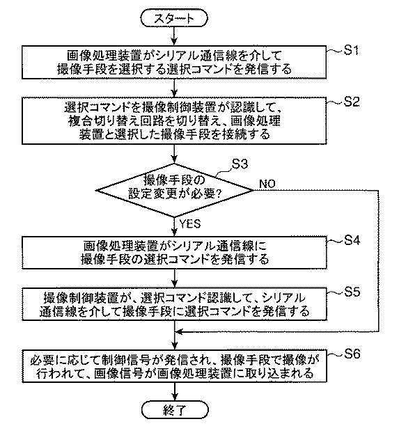
図5と表1とに示すように、本実施形態では、これら撮像手段側複合通信ケーブル37と画像処理装置側複合通信ケーブル38とは、一般の監視カメラで広く採用されているカメラリンク規格のインターフェースに準拠した構成になっている。なお、これら撮像手段側複合通信ケーブル37と、画像処理装置側複合通信ケーブル38とは、図4では省略しているが、各装置の電源のための電力線39(図5)も備えている。
As shown in FIG. 5 and Table 1, in this embodiment, the imaging means side
上記波形整形回路34は、撮像手段側複合通信ケーブル37で伝送される間に歪んだ撮像信号の波形を整形するものであり、撮像手段15、16のクロック信号に同期する位相同期回路40(PLL)を用いて歪んだ波形を整形するように構成されている。
The
次に図6を参照して、本発明の実施の形態に係る撮像制御装置30の作用について説明する。図6は、本発明の実施の形態に係る撮像制御装置30の制御要領を示すフロー図である。
Next, with reference to FIG. 6, the operation of the
図6に示すように、本発明の実施の形態に係る撮像制御装置30においては、まず、ステップS1において、画像処理装置23がシリアル通信線32を介して撮像手段15、16を選択する選択コマンドを発信する。
As shown in FIG. 6, in the
次にステップS2において、この選択コマンドを撮像制御装置30が認識して、複合切り替え回路31を切り替え、選択した撮像手段15、16と画像処理装置23とを接続する。
Next, in step S2, the
そしてステップS3において、ゲインや露光時間など、撮像手段15、16の設定変更が必要かどうかが判定され、NOの場合すなわち撮像手段15、16の設定変更が不要な場合は、ステップS6に進んで、必要に応じて制御信号が発信され、撮像手段15、16で撮像が行われて、画像信号が画像処理装置23に取り込まれる。
In step S3, it is determined whether or not setting changes of the imaging means 15 and 16 such as gain and exposure time are necessary. If NO, that is, if setting changes of the imaging means 15 and 16 are not required, the process proceeds to step S6. When necessary, a control signal is transmitted, the imaging means 15, 16 captures an image, and the image signal is taken into the
また、ステップS3において、YESすなわち、ゲインや露光時間など、撮像手段15、16の設定変更が必要な場合は、ステップS4に進み、画像処理装置23がシリアル通信線32に撮像手段15、16の設定コマンドを発信し(ステップS4)、撮像制御装置30が、設定コマンドを認識して、シリアル通信線32を介して撮像手段15、16に設定コマンドを発信し設定を変更する(ステップS5)。そして、ステップS6に進んで必要に応じて制御信号が発信され、撮像手段15、16で撮像が行われて、画像信号が画像処理装置23に取り込まれる。
If YES in step S3, that is, if it is necessary to change the settings of the imaging means 15 and 16, such as gain and exposure time, the process proceeds to step S4, where the
以上説明したように、本発明の実施の形態に係る撮像制御装置30によれば、複数の撮像手段15、16と画像処理装置23との間に設けられたシリアル通信線32が、撮像手段15、16と画像処理装置23との間で送受信するシリアル通信信号を相互に伝達し、演算回路33が、このシリアル通信信号に含まれる切り替え情報に応じて、複合切り替え回路31の撮像信号線切り替え回路31aと、制御信号線切り替え回路31bとにおける、それぞれの信号線の選択的な切り替えを制御する。その結果、シリアル通信信号に含まれる切り替え情報を介して、ゲインや露光時間などの、各監視カメラの設定変更についても撮像制御装置30側から切り替えたり、変更したりすることができるようになるなど、一つの撮像制御装置30から多様な撮像手段15、16の切り替えと制御ができるようになる。
As described above, according to the
そして、シリアル通信を利用して切り替え情報を与えるようにしているため、信号切り替えのための制御ユニットや配線を別途設ける必要がない。 Since switching information is given using serial communication, it is not necessary to separately provide a control unit and wiring for signal switching.
また、撮像手段15、16や信号処理装置30aに装脱可能な、撮像手段側複合通信ケーブル37を介してそれぞれの信号が授受されるので、撮像手段15、16と信号処理装置30aとの間の信号線にかかる配線とその取り扱いが容易になる。
In addition, since the respective signals are exchanged via the imaging means side
また、信号処理装置30aや画像処理装置23に装脱可能な、画像処理装置側複合通信ケーブル38を介してそれぞれの信号が授受されるので、信号処理装置30aと画像処理装置23との間の信号線にかかる配線とその取り扱いが容易になる。
In addition, since each signal is exchanged via the image processing apparatus side
また、画像信号線切り替え回路35cが、画像信号線35aを選択的に切り替えるとともに、クロック信号線切り替え回路35dが、クロック信号線35bを選択的に切り替えるので、画像信号としてデジタルな画像信号を複数の撮像手段15、16と画像処理装置23との間で切り替えることができるようになる。
In addition, the image signal
さらに、撮像手段15、16の切り替えを行う際に、選択した撮像手段15、16の状態にかかるレポート情報を入手したり、この撮像手段15、16の設定変更を行ったりすることができるようになる。 Further, when switching between the imaging means 15 and 16, report information relating to the state of the selected imaging means 15 and 16 can be obtained, or settings of the imaging means 15 and 16 can be changed. Become.
そして、本発明の実施の形態に係る表面実装機1によれば、表面実装機1の画像認識手段8が上記の本発明にかかる撮像制御装置30を備えているので、多様な撮像手段15、16の切り替えと制御がシリアル通信信号に含まれる切り替え情報を介して可能になる。
And according to the surface mounting machine 1 which concerns on embodiment of this invention, since the image recognition means 8 of the surface mounting machine 1 is equipped with the said
上述した実施の形態は本発明の好ましい具体例を例示したものに過ぎず、本発明は上述した実施の形態に限定されない。 The above-described embodiment is merely a preferred specific example of the present invention, and the present invention is not limited to the above-described embodiment.
例えば、本発明の実施の形態に係る表面実装機1は、必ずしも図示の形状に限定されない。移動可能なヘッドユニット7の実装用ヘッド6に設けられた吸着ノズルにより部品供給部5から電子部品を吸着した後、この電子部品を基板2上に実装するように構成されるとともに、吸着ノズルによる電子部品の吸着状態の認識などのために複数の撮像手段を備えている表面実装機であれば、種々の設計変更が可能である。
For example, the surface mounter 1 according to the embodiment of the present invention is not necessarily limited to the illustrated shape. The electronic component is adsorbed from the
また、画像認識手段8は、ヘッドユニット7に設けられた2つのマークカメラ15と、1つのサイドビューカメラ16とを備えたものに限定されない。複数の撮像手段と、これらの撮像手段が撮像した画像の画像処理を行う画像処理装置23と、本発明にかかる撮像制御装置30を備えているものであれば、種々の画像認識手段が採用可能である。
Further, the image recognition means 8 is not limited to one provided with two
さらに、撮像手段側複合通信ケーブル37と画像処理装置側複合通信ケーブル38のインターフェースのための規格としては、必ずしも図示のカメラリンク規格に限定されない。一体化された複合通信ケーブルのための規格であれば、その他種々の規格が採用可能である。
Furthermore, the standard for the interface between the imaging means side
その他、本発明の特許請求の範囲内で種々の設計変更が可能であることはいうまでもない。 In addition, it goes without saying that various design changes are possible within the scope of the claims of the present invention.
1 表面実装機
2 基板
5 部品供給部
6 実装用ヘッド
8 画像認識手段
15 マークカメラ(撮像手段)
16 サイドビューカメラ(撮像手段)
23 画像処理装置
30 撮像制御装置
30a 信号処理装置
31a 撮像信号線切り替え回路
31b 制御信号線切り替え回路
32 シリアル通信線
33 演算回路
35 撮像信号線
36 制御信号線
37 撮像手段側複合通信ケーブル
38 画像処理装置側複合通信ケーブル
35b クロック信号線
35d クロック信号線切り替え回路
DESCRIPTION OF SYMBOLS 1 Surface mounter 2 Board |
16 Side view camera (imaging means)
23
Claims (6)
撮像手段が発信した画像にかかる撮像信号を画像処理装置に伝達する各撮像手段ごとの撮像信号線と、
撮像手段の駆動を制御する制御信号を撮像手段に伝達する各撮像手段ごとの制御信号線と、
各撮像信号線および各制御信号線を介して各撮像手段に接続されるとともに各信号線を介して画像処理装置に接続される信号処理装置と、
複数の撮像手段と信号処理装置と画像処理装置とにわたって設けられ、撮像手段と画像処理装置との間で送受信するシリアル通信信号を相互に伝達するシリアル通信線とを備え、
上記信号処理装置は、
いずれかの撮像手段からの撮像信号を選択的に画像処理装置に送るように撮像信号線を切り替える撮像信号線切り替え回路と、
画像処理装置が発信した制御信号を選択的にいずれかの撮像手段に送るように制御信号線を切り替える制御信号線切り替え回路と、
上記シリアル通信線により複数の撮像手段と画像処理装置との間で伝達されるシリアル通信信号に含まれる切り替え情報に応じて、上記撮像信号線切り替え回路および制御信号線切り替え回路における切り替えを制御する演算回路とを含んでいることを特徴とする撮像制御装置。 An imaging control device provided between a plurality of imaging means and an image processing device,
An imaging signal line for each imaging means for transmitting an imaging signal relating to an image transmitted by the imaging means to the image processing device;
A control signal line for each imaging means for transmitting a control signal for controlling driving of the imaging means to the imaging means;
A signal processing device connected to each imaging means via each imaging signal line and each control signal line and connected to the image processing device via each signal line;
Provided with a plurality of imaging means, a signal processing device and an image processing device, comprising a serial communication line for mutually transmitting serial communication signals transmitted and received between the imaging means and the image processing device;
The signal processor is
An imaging signal line switching circuit that switches imaging signal lines so as to selectively send an imaging signal from any imaging means to the image processing device;
A control signal line switching circuit for switching a control signal line so as to selectively send a control signal transmitted by the image processing apparatus to any one of the imaging means;
Calculation for controlling switching in the imaging signal line switching circuit and the control signal line switching circuit according to switching information included in a serial communication signal transmitted between the plurality of imaging units and the image processing apparatus via the serial communication line An imaging control apparatus comprising a circuit.
上記撮像信号線は、この画像信号を伝達する画像信号線とクロック信号を伝達するクロック信号線とを備え、
上記撮像信号線切り替え回路は、この画像信号線を選択的に切り替える画像信号線切り替え回路とクロック信号線を選択的に切り替えるクロック信号線切り替え回路とを備えていることを特徴とする請求項1ないし請求項3のいずれか1項に記載の撮像制御装置。 The imaging signal includes an image signal of an image captured by the imaging unit and a clock signal adopted by the imaging unit,
The imaging signal line includes an image signal line for transmitting the image signal and a clock signal line for transmitting a clock signal.
The image pickup signal line switching circuit includes an image signal line switching circuit for selectively switching the image signal line and a clock signal line switching circuit for selectively switching a clock signal line. The imaging control device according to claim 3.
上記画像認識手段に設けられた撮像手段を含む複数の撮像手段と、この撮像手段が撮像した画像の画像処理を行う画像処理装置と、請求項1ないし請求項5のいずれか1項に記載の撮像制御装置を備えていることを特徴とする表面実装機。 The electronic component is adsorbed from the component supply unit by the adsorbing nozzle of the movable mounting head equipped with the adsorbing nozzle, and the adsorbing state of the electronic component adsorbed by the adsorbing nozzle is image-recognized by the image recognition means. A surface mounter for mounting electronic components on a substrate,
6. The image processing device according to claim 1, a plurality of image capturing units including an image capturing unit provided in the image recognition unit, an image processing apparatus that performs image processing of an image captured by the image capturing unit, and the image processing unit according to claim 1. A surface mounter comprising an imaging control device.
Priority Applications (1)
| Application Number | Priority Date | Filing Date | Title |
|---|---|---|---|
| JP2006272031A JP4805084B2 (en) | 2006-10-03 | 2006-10-03 | Imaging control apparatus and surface mounter |
Applications Claiming Priority (1)
| Application Number | Priority Date | Filing Date | Title |
|---|---|---|---|
| JP2006272031A JP4805084B2 (en) | 2006-10-03 | 2006-10-03 | Imaging control apparatus and surface mounter |
Publications (2)
| Publication Number | Publication Date |
|---|---|
| JP2008092355A JP2008092355A (en) | 2008-04-17 |
| JP4805084B2 true JP4805084B2 (en) | 2011-11-02 |
Family
ID=39376003
Family Applications (1)
| Application Number | Title | Priority Date | Filing Date |
|---|---|---|---|
| JP2006272031A Active JP4805084B2 (en) | 2006-10-03 | 2006-10-03 | Imaging control apparatus and surface mounter |
Country Status (1)
| Country | Link |
|---|---|
| JP (1) | JP4805084B2 (en) |
Families Citing this family (1)
| Publication number | Priority date | Publication date | Assignee | Title |
|---|---|---|---|---|
| JP6438793B2 (en) * | 2015-02-17 | 2018-12-19 | 株式会社Fuji | Multiplex communication equipment |
Family Cites Families (7)
| Publication number | Priority date | Publication date | Assignee | Title |
|---|---|---|---|---|
| JPH10233954A (en) * | 1997-02-21 | 1998-09-02 | Canon Inc | Image pickup device and image processor |
| JPH10229549A (en) * | 1997-02-14 | 1998-08-25 | Canon Inc | Video/audio input control system and adaptor |
| JPH11203578A (en) * | 1998-01-20 | 1999-07-30 | Fujitsu General Ltd | Multidisplay monitoring system |
| JP4262832B2 (en) * | 1999-05-20 | 2009-05-13 | Juki株式会社 | Image input method and apparatus |
| DE10310635A1 (en) * | 2003-03-10 | 2004-09-23 | Mobotix Ag | Monitoring device e.g. for large buildings such as prisons and airports, has response recognition store in which image data from cameras can be polled |
| JP4175956B2 (en) * | 2003-06-05 | 2008-11-05 | 三菱電機株式会社 | Camera control device and camera control system |
| JP4537233B2 (en) * | 2005-03-11 | 2010-09-01 | ヤマハ発動機株式会社 | Image recognition apparatus and surface mounter |
-
2006
- 2006-10-03 JP JP2006272031A patent/JP4805084B2/en active Active
Also Published As
| Publication number | Publication date |
|---|---|
| JP2008092355A (en) | 2008-04-17 |
Similar Documents
| Publication | Publication Date | Title |
|---|---|---|
| JP5791408B2 (en) | Electronic component mounting equipment | |
| JP6181758B2 (en) | Component mounting equipment | |
| JP2011233736A (en) | Backup pin device, backup pin arrangement method and arrangement apparatus | |
| JP2010135364A (en) | Electronic component mounting line and assembly work unit | |
| JP2005005288A (en) | Electronic component mounter and mounting method | |
| JP4769232B2 (en) | Mounting machine and component adsorption device | |
| JP6219838B2 (en) | Component mounter | |
| JP6021374B2 (en) | Component mounting apparatus and component mounting method | |
| JP2007281227A (en) | Arrangement setting method of component feeder in mounting machine | |
| JP4982287B2 (en) | BACKUP PLATE FORMING DEVICE, SURFACE MOUNTING MACHINE HAVING THE SAME, AND BACKUP PLATE FORMING METHOD | |
| JP6205161B2 (en) | Electronic component mounting equipment | |
| JP5988839B2 (en) | Component mounter | |
| JP4358013B2 (en) | Component conveying device, surface mounter and component testing device | |
| WO2015097865A1 (en) | Component mounting device and component mounting method | |
| JP4805084B2 (en) | Imaging control apparatus and surface mounter | |
| JP2007214494A (en) | Mark recognition method and surface mounter | |
| JP5850794B2 (en) | Component conveying device and component mounting machine | |
| JP2017054945A (en) | Component mounting device and imaging method in component mounting device | |
| JP4822282B2 (en) | Component mounting machine and method of using the same | |
| JP4537233B2 (en) | Image recognition apparatus and surface mounter | |
| JP4805085B2 (en) | Lighting control device and surface mounter | |
| JP2015012181A (en) | Electronic component mounting method and electronic component mounting device | |
| JP5506583B2 (en) | Component mounting method | |
| JPH06216579A (en) | Component packager | |
| US12082345B2 (en) | Component mounting machine |
Legal Events
| Date | Code | Title | Description |
|---|---|---|---|
| A621 | Written request for application examination |
Free format text: JAPANESE INTERMEDIATE CODE: A621 Effective date: 20090911 |
|
| A977 | Report on retrieval |
Free format text: JAPANESE INTERMEDIATE CODE: A971007 Effective date: 20110728 |
|
| TRDD | Decision of grant or rejection written | ||
| A01 | Written decision to grant a patent or to grant a registration (utility model) |
Free format text: JAPANESE INTERMEDIATE CODE: A01 Effective date: 20110809 |
|
| A01 | Written decision to grant a patent or to grant a registration (utility model) |
Free format text: JAPANESE INTERMEDIATE CODE: A01 |
|
| A61 | First payment of annual fees (during grant procedure) |
Free format text: JAPANESE INTERMEDIATE CODE: A61 Effective date: 20110810 |
|
| R150 | Certificate of patent or registration of utility model |
Ref document number: 4805084 Country of ref document: JP Free format text: JAPANESE INTERMEDIATE CODE: R150 Free format text: JAPANESE INTERMEDIATE CODE: R150 |
|
| FPAY | Renewal fee payment (event date is renewal date of database) |
Free format text: PAYMENT UNTIL: 20140819 Year of fee payment: 3 |
|
| R250 | Receipt of annual fees |
Free format text: JAPANESE INTERMEDIATE CODE: R250 |
|
| R250 | Receipt of annual fees |
Free format text: JAPANESE INTERMEDIATE CODE: R250 |
|
| R250 | Receipt of annual fees |
Free format text: JAPANESE INTERMEDIATE CODE: R250 |
|
| R250 | Receipt of annual fees |
Free format text: JAPANESE INTERMEDIATE CODE: R250 |
|
| R250 | Receipt of annual fees |
Free format text: JAPANESE INTERMEDIATE CODE: R250 |
|
| R250 | Receipt of annual fees |
Free format text: JAPANESE INTERMEDIATE CODE: R250 |
|
| R250 | Receipt of annual fees |
Free format text: JAPANESE INTERMEDIATE CODE: R250 |
|
| R250 | Receipt of annual fees |
Free format text: JAPANESE INTERMEDIATE CODE: R250 |
|
| R250 | Receipt of annual fees |
Free format text: JAPANESE INTERMEDIATE CODE: R250 |
|
| R250 | Receipt of annual fees |
Free format text: JAPANESE INTERMEDIATE CODE: R250 |
|
| R250 | Receipt of annual fees |
Free format text: JAPANESE INTERMEDIATE CODE: R250 |