WO2014129565A1 - Dispositif - Google Patents
Dispositif Download PDFInfo
- Publication number
- WO2014129565A1 WO2014129565A1 PCT/JP2014/054090 JP2014054090W WO2014129565A1 WO 2014129565 A1 WO2014129565 A1 WO 2014129565A1 JP 2014054090 W JP2014054090 W JP 2014054090W WO 2014129565 A1 WO2014129565 A1 WO 2014129565A1
- Authority
- WO
- WIPO (PCT)
- Prior art keywords
- display
- display area
- panel
- touch screen
- mobile phone
- Prior art date
Links
Images


Classifications
-
- G—PHYSICS
- G06—COMPUTING; CALCULATING OR COUNTING
- G06F—ELECTRIC DIGITAL DATA PROCESSING
- G06F3/00—Input arrangements for transferring data to be processed into a form capable of being handled by the computer; Output arrangements for transferring data from processing unit to output unit, e.g. interface arrangements
- G06F3/01—Input arrangements or combined input and output arrangements for interaction between user and computer
- G06F3/048—Interaction techniques based on graphical user interfaces [GUI]
- G06F3/0487—Interaction techniques based on graphical user interfaces [GUI] using specific features provided by the input device, e.g. functions controlled by the rotation of a mouse with dual sensing arrangements, or of the nature of the input device, e.g. tap gestures based on pressure sensed by a digitiser
- G06F3/0488—Interaction techniques based on graphical user interfaces [GUI] using specific features provided by the input device, e.g. functions controlled by the rotation of a mouse with dual sensing arrangements, or of the nature of the input device, e.g. tap gestures based on pressure sensed by a digitiser using a touch-screen or digitiser, e.g. input of commands through traced gestures
- G06F3/04883—Interaction techniques based on graphical user interfaces [GUI] using specific features provided by the input device, e.g. functions controlled by the rotation of a mouse with dual sensing arrangements, or of the nature of the input device, e.g. tap gestures based on pressure sensed by a digitiser using a touch-screen or digitiser, e.g. input of commands through traced gestures for inputting data by handwriting, e.g. gesture or text
-
- G—PHYSICS
- G06—COMPUTING; CALCULATING OR COUNTING
- G06F—ELECTRIC DIGITAL DATA PROCESSING
- G06F1/00—Details not covered by groups G06F3/00 - G06F13/00 and G06F21/00
- G06F1/16—Constructional details or arrangements
- G06F1/1613—Constructional details or arrangements for portable computers
- G06F1/1626—Constructional details or arrangements for portable computers with a single-body enclosure integrating a flat display, e.g. Personal Digital Assistants [PDAs]
-
- G—PHYSICS
- G06—COMPUTING; CALCULATING OR COUNTING
- G06F—ELECTRIC DIGITAL DATA PROCESSING
- G06F1/00—Details not covered by groups G06F3/00 - G06F13/00 and G06F21/00
- G06F1/16—Constructional details or arrangements
- G06F1/1613—Constructional details or arrangements for portable computers
- G06F1/1633—Constructional details or arrangements of portable computers not specific to the type of enclosures covered by groups G06F1/1615 - G06F1/1626
- G06F1/1637—Details related to the display arrangement, including those related to the mounting of the display in the housing
- G06F1/1643—Details related to the display arrangement, including those related to the mounting of the display in the housing the display being associated to a digitizer, e.g. laptops that can be used as penpads
-
- G—PHYSICS
- G06—COMPUTING; CALCULATING OR COUNTING
- G06F—ELECTRIC DIGITAL DATA PROCESSING
- G06F1/00—Details not covered by groups G06F3/00 - G06F13/00 and G06F21/00
- G06F1/16—Constructional details or arrangements
- G06F1/1613—Constructional details or arrangements for portable computers
- G06F1/1633—Constructional details or arrangements of portable computers not specific to the type of enclosures covered by groups G06F1/1615 - G06F1/1626
- G06F1/1637—Details related to the display arrangement, including those related to the mounting of the display in the housing
- G06F1/1647—Details related to the display arrangement, including those related to the mounting of the display in the housing including at least an additional display
-
- G—PHYSICS
- G06—COMPUTING; CALCULATING OR COUNTING
- G06F—ELECTRIC DIGITAL DATA PROCESSING
- G06F1/00—Details not covered by groups G06F3/00 - G06F13/00 and G06F21/00
- G06F1/16—Constructional details or arrangements
- G06F1/1613—Constructional details or arrangements for portable computers
- G06F1/1633—Constructional details or arrangements of portable computers not specific to the type of enclosures covered by groups G06F1/1615 - G06F1/1626
- G06F1/1637—Details related to the display arrangement, including those related to the mounting of the display in the housing
- G06F1/1652—Details related to the display arrangement, including those related to the mounting of the display in the housing the display being flexible, e.g. mimicking a sheet of paper, or rollable
-
- G—PHYSICS
- G06—COMPUTING; CALCULATING OR COUNTING
- G06F—ELECTRIC DIGITAL DATA PROCESSING
- G06F1/00—Details not covered by groups G06F3/00 - G06F13/00 and G06F21/00
- G06F1/16—Constructional details or arrangements
- G06F1/1613—Constructional details or arrangements for portable computers
- G06F1/1633—Constructional details or arrangements of portable computers not specific to the type of enclosures covered by groups G06F1/1615 - G06F1/1626
- G06F1/1684—Constructional details or arrangements related to integrated I/O peripherals not covered by groups G06F1/1635 - G06F1/1675
-
- G—PHYSICS
- G06—COMPUTING; CALCULATING OR COUNTING
- G06F—ELECTRIC DIGITAL DATA PROCESSING
- G06F3/00—Input arrangements for transferring data to be processed into a form capable of being handled by the computer; Output arrangements for transferring data from processing unit to output unit, e.g. interface arrangements
- G06F3/01—Input arrangements or combined input and output arrangements for interaction between user and computer
- G06F3/017—Gesture based interaction, e.g. based on a set of recognized hand gestures
-
- G—PHYSICS
- G06—COMPUTING; CALCULATING OR COUNTING
- G06F—ELECTRIC DIGITAL DATA PROCESSING
- G06F3/00—Input arrangements for transferring data to be processed into a form capable of being handled by the computer; Output arrangements for transferring data from processing unit to output unit, e.g. interface arrangements
- G06F3/01—Input arrangements or combined input and output arrangements for interaction between user and computer
- G06F3/03—Arrangements for converting the position or the displacement of a member into a coded form
- G06F3/033—Pointing devices displaced or positioned by the user, e.g. mice, trackballs, pens or joysticks; Accessories therefor
- G06F3/0354—Pointing devices displaced or positioned by the user, e.g. mice, trackballs, pens or joysticks; Accessories therefor with detection of 2D relative movements between the device, or an operating part thereof, and a plane or surface, e.g. 2D mice, trackballs, pens or pucks
- G06F3/03547—Touch pads, in which fingers can move on a surface
-
- G—PHYSICS
- G06—COMPUTING; CALCULATING OR COUNTING
- G06F—ELECTRIC DIGITAL DATA PROCESSING
- G06F3/00—Input arrangements for transferring data to be processed into a form capable of being handled by the computer; Output arrangements for transferring data from processing unit to output unit, e.g. interface arrangements
- G06F3/01—Input arrangements or combined input and output arrangements for interaction between user and computer
- G06F3/03—Arrangements for converting the position or the displacement of a member into a coded form
- G06F3/041—Digitisers, e.g. for touch screens or touch pads, characterised by the transducing means
- G06F3/0412—Digitisers structurally integrated in a display
-
- G—PHYSICS
- G06—COMPUTING; CALCULATING OR COUNTING
- G06F—ELECTRIC DIGITAL DATA PROCESSING
- G06F3/00—Input arrangements for transferring data to be processed into a form capable of being handled by the computer; Output arrangements for transferring data from processing unit to output unit, e.g. interface arrangements
- G06F3/01—Input arrangements or combined input and output arrangements for interaction between user and computer
- G06F3/03—Arrangements for converting the position or the displacement of a member into a coded form
- G06F3/041—Digitisers, e.g. for touch screens or touch pads, characterised by the transducing means
- G06F3/0416—Control or interface arrangements specially adapted for digitisers
-
- G—PHYSICS
- G06—COMPUTING; CALCULATING OR COUNTING
- G06F—ELECTRIC DIGITAL DATA PROCESSING
- G06F3/00—Input arrangements for transferring data to be processed into a form capable of being handled by the computer; Output arrangements for transferring data from processing unit to output unit, e.g. interface arrangements
- G06F3/01—Input arrangements or combined input and output arrangements for interaction between user and computer
- G06F3/048—Interaction techniques based on graphical user interfaces [GUI]
- G06F3/0481—Interaction techniques based on graphical user interfaces [GUI] based on specific properties of the displayed interaction object or a metaphor-based environment, e.g. interaction with desktop elements like windows or icons, or assisted by a cursor's changing behaviour or appearance
- G06F3/04817—Interaction techniques based on graphical user interfaces [GUI] based on specific properties of the displayed interaction object or a metaphor-based environment, e.g. interaction with desktop elements like windows or icons, or assisted by a cursor's changing behaviour or appearance using icons
-
- G—PHYSICS
- G06—COMPUTING; CALCULATING OR COUNTING
- G06F—ELECTRIC DIGITAL DATA PROCESSING
- G06F3/00—Input arrangements for transferring data to be processed into a form capable of being handled by the computer; Output arrangements for transferring data from processing unit to output unit, e.g. interface arrangements
- G06F3/01—Input arrangements or combined input and output arrangements for interaction between user and computer
- G06F3/048—Interaction techniques based on graphical user interfaces [GUI]
- G06F3/0484—Interaction techniques based on graphical user interfaces [GUI] for the control of specific functions or operations, e.g. selecting or manipulating an object, an image or a displayed text element, setting a parameter value or selecting a range
- G06F3/0485—Scrolling or panning
-
- G—PHYSICS
- G06—COMPUTING; CALCULATING OR COUNTING
- G06F—ELECTRIC DIGITAL DATA PROCESSING
- G06F3/00—Input arrangements for transferring data to be processed into a form capable of being handled by the computer; Output arrangements for transferring data from processing unit to output unit, e.g. interface arrangements
- G06F3/01—Input arrangements or combined input and output arrangements for interaction between user and computer
- G06F3/048—Interaction techniques based on graphical user interfaces [GUI]
- G06F3/0487—Interaction techniques based on graphical user interfaces [GUI] using specific features provided by the input device, e.g. functions controlled by the rotation of a mouse with dual sensing arrangements, or of the nature of the input device, e.g. tap gestures based on pressure sensed by a digitiser
- G06F3/0488—Interaction techniques based on graphical user interfaces [GUI] using specific features provided by the input device, e.g. functions controlled by the rotation of a mouse with dual sensing arrangements, or of the nature of the input device, e.g. tap gestures based on pressure sensed by a digitiser using a touch-screen or digitiser, e.g. input of commands through traced gestures
-
- G—PHYSICS
- G06—COMPUTING; CALCULATING OR COUNTING
- G06F—ELECTRIC DIGITAL DATA PROCESSING
- G06F2203/00—Indexing scheme relating to G06F3/00 - G06F3/048
- G06F2203/041—Indexing scheme relating to G06F3/041 - G06F3/045
- G06F2203/04101—2.5D-digitiser, i.e. digitiser detecting the X/Y position of the input means, finger or stylus, also when it does not touch, but is proximate to the digitiser's interaction surface and also measures the distance of the input means within a short range in the Z direction, possibly with a separate measurement setup
-
- G—PHYSICS
- G06—COMPUTING; CALCULATING OR COUNTING
- G06F—ELECTRIC DIGITAL DATA PROCESSING
- G06F2203/00—Indexing scheme relating to G06F3/00 - G06F3/048
- G06F2203/041—Indexing scheme relating to G06F3/041 - G06F3/045
- G06F2203/04102—Flexible digitiser, i.e. constructional details for allowing the whole digitising part of a device to be flexed or rolled like a sheet of paper
-
- G—PHYSICS
- G06—COMPUTING; CALCULATING OR COUNTING
- G06F—ELECTRIC DIGITAL DATA PROCESSING
- G06F2203/00—Indexing scheme relating to G06F3/00 - G06F3/048
- G06F2203/041—Indexing scheme relating to G06F3/041 - G06F3/045
- G06F2203/04103—Manufacturing, i.e. details related to manufacturing processes specially suited for touch sensitive devices
-
- G—PHYSICS
- G06—COMPUTING; CALCULATING OR COUNTING
- G06F—ELECTRIC DIGITAL DATA PROCESSING
- G06F2203/00—Indexing scheme relating to G06F3/00 - G06F3/048
- G06F2203/041—Indexing scheme relating to G06F3/041 - G06F3/045
- G06F2203/04104—Multi-touch detection in digitiser, i.e. details about the simultaneous detection of a plurality of touching locations, e.g. multiple fingers or pen and finger
-
- G—PHYSICS
- G06—COMPUTING; CALCULATING OR COUNTING
- G06F—ELECTRIC DIGITAL DATA PROCESSING
- G06F2203/00—Indexing scheme relating to G06F3/00 - G06F3/048
- G06F2203/048—Indexing scheme relating to G06F3/048
- G06F2203/04803—Split screen, i.e. subdividing the display area or the window area into separate subareas
Definitions
- the present invention relates to an apparatus having a touch screen display.
- a device equipped with a touch screen display is known.
- Devices that include a touch screen display include, for example, smartphones and tablets.
- a device with a touch screen display detects a finger or stylus pen gesture via the touch screen display.
- the device including the touch screen display operates according to the detected gesture.
- An example of the operation according to the detected gesture is described in Patent Document 1, for example.
- OS such as Android (registered trademark), BlackBerry (registered trademark) OS, Symbian (registered trademark) OS, iOS, Windows (registered trademark) Phone, etc. It is realized by Operating (System).
- An object of the present invention is to provide an apparatus with improved operability.
- An apparatus includes a housing having a first surface, a second surface, a third surface connecting the first surface and the second surface, and the third surface of the housing.
- a touch screen disposed in the housing, and a display disposed in the housing, wherein the display includes at least one first display area for displaying on the first surface and a second display area for displaying on the second surface.
- the display includes at least one first display area for displaying on the first surface and a second display area for displaying on the second surface.
- the first operation is a first gesture operation from the third surface toward the first surface
- the second operation is performed from the third surface to the second surface.
- the second gesture operation may be performed.
- the first operation and the second operation may be operations on the same icon on the touch screen.
- the controller may change a call volume according to a swipe operation on the touch screen on the third surface.
- the display may be one flexible display, and the flexible display includes the first display area and the second display area.
- An apparatus includes a housing having a first surface, a second surface, and a third surface that connects the first surface and the second surface, and is disposed in the housing.
- a flexible display comprising a first display area for displaying on the first surface, a second display area for displaying on the second surface, and a third display area for displaying on the third surface;
- a posture detection unit that detects a posture; and a controller that controls display of the third display area in accordance with the posture detected by the posture detection unit.
- the apparatus may include a proximity sensor that determines whether or not the object is close to the object, and the controller detects the posture detected by the posture detection unit in a vertical direction, and the proximity sensor When it is determined that the object is close to the object, the third display area may be controlled to display predetermined information.
- the posture detection unit may be configured such that one of the first display area and the second display area is located above the other of the first display area and the second display area.
- the controller may display predetermined information on the one of the first display area and the second display area located above the other.
- An apparatus is a housing, a panel attached to the housing, and a third surface that connects the first surface, the second surface, the first surface, and the second surface.
- a display attached to the panel, a first display area for displaying on the first surface, a second display area for displaying on the second surface, and a display on the third surface A display having a third display area; and a piezoelectric element attached to the display, wherein the panel is deformed due to deformation of the piezoelectric element, and transmits a human body vibration sound to an object in contact with the panel.
- a device with improved operability can be provided.
- FIG. 1 is a front view of a mobile phone.
- FIG. 2 is a rear view of the mobile phone.
- FIG. 3 is a top view of the mobile phone.
- FIG. 4 is a sectional view schematically showing a IV-IV section of the mobile phone.
- FIG. 5 is a cross-sectional view schematically showing a VV cross section of a mobile phone.
- FIG. 6 is a block diagram of the mobile phone according to the embodiment.
- 7A, FIG. 7B, and FIG. 7C are diagrams showing display modes in a plurality of display areas of the display.
- 8A and 8B are diagrams showing a first example of display control in a plurality of display areas of the display.
- 9A and 9B are diagrams illustrating a second example of display control in a plurality of display areas of the display.
- 10A and 10B are diagrams illustrating a third example of display control in a plurality of display areas of the display.
- 11A and 11B are diagrams showing a fourth example of display control in a plurality of display areas of the display.
- 12A and 12B are diagrams illustrating a first example of control according to a gesture for the third display region.
- 13A and 13B are diagrams illustrating a second example of control according to a gesture for the third display region.
- FIG. 1 is a front view of the mobile phone 1.
- FIG. 2 is a rear view of the mobile phone 1.
- FIG. 3 is a top view of the mobile phone 1.
- FIG. 4 is a cross-sectional view schematically showing a cross section IV-IV of the mobile phone 1.
- FIG. 5 is a cross-sectional view schematically showing a VV cross section of the mobile phone 1.
- the mobile phone 1 includes an illuminance sensor 4, a proximity sensor 5, a piezoelectric element 7, a first microphone 8 a and a second microphone 8 b, and a camera 12 on a front surface (first surface) 1 ⁇ / b> A.
- the panel 20a and the touch screen 21 are provided.
- the cellular phone 1 includes a camera 14, a panel 20b, and a touch screen 22 on the back surface (second surface) 1B.
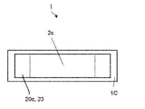
- the mobile phone 1 includes a panel 20c and a touch screen 23 on an upper surface (third surface) 1C.
- the mobile phone 1 has a structural design in which a large display is provided on the surface of the device and microphones are provided at symmetrical positions on both ends of the casing 40 in the longitudinal direction.
- the cellular phone 1 is almost the same when the end of the casing 40 in the longitudinal direction on the first microphone 8a side is up and the casing 40 in the longitudinal direction of the casing 40 on the second microphone 8b side. There is no difference in appearance.
- the display 2 is a display device such as a flexible organic EL display (OELD: Organic Electro-Luminescence Display). As shown in FIG. 4, the display 2 is arranged in a folded state inside the housing 40.
- the display 2 displays characters, images, symbols, graphics, and the like.
- the display 2 has a first display area 2a, a second display area 2b, and a third display area 2c.
- the display 2 can display the same information or different information on each of the first display area 2a, the second display area 2b, and the third display area 2c under the control of the controller 10 described later.
- the display 2 controls whether information is displayed or not displayed in each of the first display area 2a, the second display area 2b, and the third display area 2c under the control of the controller 10 described later.
- the content displayed in the first display area 2a is visible from the front 1A side via the panel 20a and the touch screen 21.
- the content displayed in the second display area 2b is visible from the back surface 1B side through the panel 20b and the touch screen 22.
- the content displayed in the third display area 2c is visible from the upper surface 1C side through the panel 20c and the touch screen 23.
- the illuminance sensor 4 detects the illuminance of the ambient light of the mobile phone 1. Illuminance indicates light intensity, brightness, or luminance. The illuminance sensor 4 is used for adjusting the luminance of the display 2, for example.
- the proximity sensor 5 detects the presence of a nearby object without contact. The proximity sensor 5 detects the presence of an object based on a change in a magnetic field or a change in a feedback time of an ultrasonic reflected wave. For example, the proximity sensor 5 detects that the display 2 is brought close to the face.
- the illuminance sensor 4 and the proximity sensor 5 may be configured as one sensor. The illuminance sensor 4 may be used as a proximity sensor.
- the piezoelectric element 7 expands or contracts or bends according to the electromechanical coupling coefficient of the constituent material when an electric signal (voltage corresponding to the sound signal) is applied. That is, the piezoelectric element 7 is deformed when an electric signal is applied.
- the piezoelectric element 7 is attached to the panel 20a and used as a vibration source for vibrating the panel 20a.
- the piezoelectric element 7 is formed using, for example, ceramic or quartz.
- the piezoelectric element 7 may be a unimorph type, a bimorph type, or a laminated type piezoelectric element.
- the multilayer piezoelectric element includes a multilayer bimorph element in which bimorphs are stacked (for example, 16 layers or 24 layers are stacked).
- the multilayer piezoelectric element is composed of, for example, a multilayer structure including a plurality of dielectric layers made of PZT (lead zirconate titanate) and electrode layers disposed between the plurality of dielectric layers.
- the unimorph type expands and contracts when an electric signal (voltage) is applied.
- the bimorph type bends when an electric signal (voltage) is applied.
- the first microphone 8a and the second microphone 8b are sound input units.
- the first microphone 8 a and the second microphone 8 b convert the input sound into an electrical signal and send it to the controller 10.
- the first microphone 8a and the second microphone 8b collect (input) voices uttered by the user during a call.
- the camera 12 converts the captured image into an electrical signal and sends it to the controller 10.
- the camera 12 includes, for example, an in-camera that captures an object facing the display 2 and an out-camera that captures an object facing the opposite surface of the display 2.
- the panel 20a vibrates as the piezoelectric element 7 is deformed (stretched or bent), and transmits the vibration to the ear cartilage (auricular cartilage) or the like that the user contacts with the panel 20a.
- the panel 20a is made of, for example, a synthetic resin such as glass or acrylic.
- the shape of the panel 20a is, for example, a plate shape.
- the panel 20a may be a flat plate.
- the panel 20a may be a curved panel whose surface is smoothly curved.
- the panel 20a may be a battery lid.
- the battery lid is a member that is attached to the housing 40 and covers the battery.
- the piezoelectric element 7 may be configured to vibrate corners of the housing 40 (for example, at least one of the four corners).
- the piezoelectric element 7 may be configured to be attached to the inner surface of the corner portion of the housing 40, and further includes an intermediate member, and vibration of the piezoelectric element 7 is transmitted to the corner portion of the housing 40 via the intermediate member. It may be configured. According to this configuration, the vibrating range can be made relatively narrow, so that air conduction sound generated by the vibration is difficult to leak to the surroundings. Further, according to this configuration, for example, air conduction sound and vibration sound are transmitted to the user in a state where the user inserts the corner portion of the housing 40 into the ear canal, so that ambient noise is difficult to enter the user's ear canal. . Therefore, the quality of the sound transmitted to the user can be improved.
- the display 2 and the piezoelectric element 7 are attached to the back surface of the panel 20a by the joining member 30 (see FIG. 5).
- the piezoelectric element 7 is spaced from the inner surface of the housing 40 by a predetermined distance while being arranged on the back surface of the panel 20a.
- the piezoelectric element 7 may be separated from the inner surface of the housing 40 even in a stretched or bent state. That is, the distance between the piezoelectric element 7 and the inner surface of the housing 40 is preferably larger than the maximum deformation amount of the piezoelectric element 7.
- the piezoelectric element 7 may be attached to the panel 20a via a reinforcing member (for example, sheet metal or glass fiber reinforced resin).
- the joining member 30 is, for example, a double-sided tape or an adhesive having thermosetting property or ultraviolet curable property.
- the joining member 30 may be an optical elastic resin that is a colorless and transparent acrylic ultraviolet curable adhesive.
- the piezoelectric element 7 is arranged in the vicinity of a predetermined distance from the short-side end of the panel 20a so that the longitudinal direction of the piezoelectric element 7 is parallel to the longitudinal direction of the panel 20a (see FIG. 1). ).
- the center in the longitudinal direction of the piezoelectric element 7 is located on a straight line that passes through the center in the longitudinal direction of the panel 20a and is parallel to the short direction of the panel 20a.
- the piezoelectric element 7 may be attached to each of the areas 7a, 7b, 7c on the back surface of the display 2, or one or two of the areas 7a, 7b, 7c. It may be attached to.
- the display 2 to which the piezoelectric element 7 is attached is deformed in accordance with expansion / contraction or bending of the piezoelectric element 7.
- the panel 20 to which the display 2 is attached is also deformed in accordance with the deformation of the display 2. At this time, when the user brings a part of the body (auricular cartilage) into contact with the panel 20, the panel 20 generates a vibration sound (human body vibration sound) transmitted to the user through the part of the body.
- the piezoelectric element 7 When the piezoelectric element 7 is attached to the region 7a, vibration generated by the deformation of the piezoelectric element 7 is transmitted to the panel 20a via the display 2, and the panel 20a is deformed. Since the panel 20a has substantially the same size as the front surface of the mobile phone 1, for example, it is possible to easily generate the vibration of the panel 20 in a region larger than the user's ear.
- the piezoelectric element 7 is attached to the region 7b, vibration generated by the deformation of the piezoelectric element 7 is transmitted to the panel 20b through the display 2, and the panel 20b is deformed.
- the panel 20b has substantially half the size of the panel 20a, and the area of the panel 20 that vibrates due to the deformation of the piezoelectric element 7 is made smaller than when the piezoelectric element 7 is attached to the area 7a. Sound leakage can be reduced.
- the piezoelectric element 7 is attached to the region 7c, vibration caused by the deformation of the piezoelectric element 7 is transmitted to the panel 20c via the display 2, and the panel 20c is deformed. At this time, since the vibration of the piezoelectric element 7 propagates to both the regions 7a and 7b connected to the region 7c of the display 2, the panels 20a and 20b are also deformed together.
- the user can hear the sound by putting his / her ear on either the front surface or the back surface of the mobile phone 1.
- the piezoelectric element 7 may be attached to the area
- the touch screen (touch sensor) 21 is disposed so as to overlap the display 2.
- the touch screen 21 detects contact. Based on the contact detected by the touch screen 21, the controller 10 (the mobile phone 1) uses the finger, stylus, pen, etc. (hereinafter simply referred to as “finger”) to perform various operations on the touch screen 21 ( Gesture).
- the touch screen 21 has a touch sensor.
- the touch sensor detects the contact of the finger on the touch screen 21 together with the position on the touch screen 21 of the touched location, and notifies the controller 10 of it.
- the controller 10 detects a user operation (gesture) on the surface of the display 20 by cooperating with the touch screen 21.
- Various operations (gestures) detected by the controller 10 via the touch screen 21 include, for example, touch, long touch, release, swipe, tap, double tap, long tap, drag, flick, pinch in, and pinch out.
- the detection method of the touch screen 21 may be any method such as a capacitance method, a resistive film method, a surface acoustic wave method (or an ultrasonic method), an infrared method, an electromagnetic induction method, and a load detection method.
- the display 2 and the touch screen 21 are functionally separated, but may be physically integrated as a touch screen display.
- the contact detected by the touch screen 21 includes an auricle contact with the panel 20a.
- the touch screen 22 is disposed on the back surface 1B of the mobile phone 1. In the present embodiment, the touch screen 22 has about half the size of the touch screen 21.
- the touch screen 23 is disposed on the upper surface 1 ⁇ / b> C of the mobile phone 1.
- the touch screen 22 detects contact with the back surface, and the touch screen 23 detects contact with the top surface.
- the detection result of the touch screen 22 or the touch screen 23 is used to detect a user's contact operation with a finger, a pen, a stylus pen, or the like.
- the operation (gesture) determined based on the contact detected using the touch screen 22 or the touch screen 23 is, for example, touch, long touch, release, swipe, tap, double tap, long tap, drag, flick, pinch in , And pinch out.
- the detection method of the touch screen 22 or the touch screen 23 may be any method such as a capacitance method, a resistive film method, a surface acoustic wave method (or an ultrasonic method), an infrared method, an electromagnetic induction method, and a load detection method. .
- the detection method of the touch screen 22 or the touch screen 23 may be different from the detection method of the touch screen 21.
- the housing 40 is formed using resin or metal.
- the housing 40 supports the display 2, the illuminance sensor 4, the proximity sensor 5, the first microphone 8a, the second microphone 8b, the camera 12, the panel 20a, and the like.
- An electrical signal corresponding to the output sound is applied to the piezoelectric element 7.
- ⁇ 15 V higher than ⁇ 5 V which is an applied voltage of a so-called panel speaker that transmits sound by air conduction sound through the ear canal, may be applied to the piezoelectric element 7.
- the piezoelectric element 7 can vibrate sufficiently to the panel 20a. And vibration sound transmitted through a part of the user's body can be generated.
- the voltage applied to the piezoelectric element 7 can be appropriately adjusted according to the fixing strength of the panel 20a with respect to the housing 40, the performance of the piezoelectric element 7, or the like.
- the piezoelectric element 7 When an electric signal is applied, the piezoelectric element 7 expands or contracts or bends in the longitudinal direction.
- the panel 20 a to which the piezoelectric element 7 is attached is deformed in accordance with expansion / contraction or bending of the piezoelectric element 7. Thereby, the panel 20a vibrates and generates air conduction sound. Further, when the user brings a part of the body (for example, auricular cartilage) into contact with the panel 20a, the panel 20a generates a vibration sound that is transmitted to the user through the part of the body. That is, as the piezoelectric element 7 is deformed, the panel 20a vibrates at a frequency that is perceived as vibration sound with respect to an object that contacts the panel 20a.
- a part of the body for example, auricular cartilage
- the panel 20a when an electrical signal corresponding to the voice of the other party of the call or sound data such as a ring tone or music is applied to the piezoelectric element 7, the panel 20a generates an air conduction sound and a vibration sound corresponding to the electrical signal.
- the sound signal output via the piezoelectric element 7 and the panel 20a may be based on sound data stored in the storage 9 described later.
- the sound signal output via the piezoelectric element 7 and the panel 20a may be based on sound data stored in an external server or the like and acquired via the network by the communication unit 6 described later.
- the panel 20a may be approximately the same size as the user's ear.
- the panel 20a may be larger than the user's ear. In this case, the user can bring the entire outer periphery of the ear into contact with the panel 20a when listening to the sound. Listening to the sound in this way makes it difficult for ambient sounds (noise) to enter the ear canal.
- at least the panel 20a has a length in the longitudinal direction (or short direction) corresponding to the distance from the lower leg of the anti-annulus (lower anti-annular leg) to the anti-tragus, and the distance from the tragus.
- a region wider than a region having a length in the short direction (or the longitudinal direction) corresponding to the distance to the ear ring vibrates.
- the panel 20a includes a length in the longitudinal direction (or short direction) corresponding to the distance from the region near the upper leg of the ear ring (upper pair leg) in the ear ring to the earlobe, and the vicinity of the ear ring in the ear ring from the tragus.
- a region having a length in the short direction (or the longitudinal direction) corresponding to the distance to the part may vibrate.
- the region having the above length and width may be a rectangular region, or an elliptical shape in which the length in the longitudinal direction is the major axis and the length in the lateral direction is the minor axis. Also good.
- the average size of the human ear can be found, for example, by referring to the Japanese human body size database (1992-1994) created by the Human Life Engineering Research Center (HQL).
- the panel 20a vibrates not only in the attachment region 20a to which the piezoelectric element 7 is attached, but also in a region away from the attachment region 20a.
- the panel 20a has a plurality of locations that vibrate in a direction intersecting the main surface of the panel 20a in the vibrating region, and in each of the plurality of locations, the value of the amplitude of vibration changes from positive to negative with time, Or vice versa.
- the panel 20a vibrates at a seemingly random or regular distribution in a portion where the vibration amplitude is relatively large and a portion where the vibration amplitude is relatively small. That is, vibrations of a plurality of waves are detected over the entire panel 20a.
- the cellular phone 1 can transmit the air conduction sound and the vibration sound through a part of the user's body (for example, auricular cartilage) to the user by the vibration of the panel 20a. Therefore, when the mobile phone 1 outputs a sound having a volume equivalent to that of a dynamic receiver, the sound transmitted to the surroundings of the mobile phone 1 due to air vibrations may be reduced compared to an electronic device having only a dynamic speaker. it can.
- a feature is suitable, for example, when listening to a recorded message in a place where there is another person nearby, such as in a train.
- the mobile phone 1 transmits a vibration sound to the user by the vibration of the panel 20a. Therefore, even if the user wears the earphone or the headphone, the user can hear the vibration sound caused by the vibration of the panel 20a through the earphone or the headphone and a part of the body by bringing the mobile phone 1 into contact therewith. it can.
- the mobile phone 1 transmits sound by vibration of the panel 20a. Therefore, when the mobile phone 1 does not include a separate dynamic receiver, it is not necessary to form an opening (sound outlet) in the housing 40 for transmitting the sound generated by the panel 20a to the outside. For this reason, when realizing a waterproof structure, the structure can be simplified.
- the cellular phone 1 closes the opening with a member that allows gas to pass but not liquid to realize a waterproof structure.
- a structure may be adopted.
- An example of the member that allows gas to pass but not liquid is Gore-Tex (registered trademark).
- the mobile phone 1 may have a speaker such as a dynamic speaker, for example.
- the combination of the piezoelectric element 7 and the panel 20a may be referred to as a vibration receiver.
- FIG. 6 is a block diagram of the mobile phone 1 according to the embodiment.
- the mobile phone 1 includes a display 2, an illuminance sensor 4, a proximity sensor 5, a communication unit 6, a piezoelectric element 7, a first microphone 8 a, a second microphone 8 b, and a storage 9.
- a controller 10 a camera 12, a vibration receiver 13 including a piezoelectric element 7 and a panel 20 a, a posture detection unit 15, a vibrator 18, and a touch screen 21.
- the communication unit 6 communicates wirelessly.
- the communication method supported by the communication unit 6 is a wireless communication standard.
- wireless communication standards include cellular phone communication standards such as 2G, 3G, and 4G.
- Cellular phone communication standards include, for example, LTE (Long-Term Evolution), W-CDMA (Wideband Code Division-Multiple Access), CDMA2000, PDC (Personal Digital Digital), GSM (registered trademark), Global SM Personal Handy-phone System).
- wireless communication standards for example, there are WiMAX (WorldwideWInteroperability for Microwave Access), IEEE802.11, Bluetooth (registered trademark), IrDA (Infrared Data Association), NFC (Near Frequency, etc.).
- the communication unit 6 may support one or more of the communication standards described above.
- the storage 9 stores programs and data.
- the storage 9 is also used as a work area for temporarily storing the processing result of the controller 10.
- the storage 9 may include any non-transitory storage medium such as a semiconductor storage medium and a magnetic storage medium.
- the storage 9 may include a plurality of types of storage media.
- the storage 9 may include a combination of a portable storage medium such as a memory card, an optical disk, or a magneto-optical disk and a storage medium reader.
- the storage 9 may include a storage device that is used as a temporary storage area such as a RAM (RandomoAccess Memory).
- the program stored in the storage 9 includes an application executed in the foreground or the background and a control program that supports the operation of the application.
- an application executed in the foreground displays a screen on the display 2.
- the control program includes an OS, for example.
- the application and the control program may be installed in the storage 9 via wireless communication by the communication unit 6 or a non-transitory storage medium.
- the storage 9 stores, for example, a control program 9A, a call application 9B, a music playback application 9C, a video playback application 9D, and setting data 9Z.
- the call application 9B provides a call function for a call by wireless communication.
- the music playback application 9C provides a music playback function for playing back sound from music data.
- the video playback application 9D provides a video playback function for playing back video and sound from video data.
- the setting data 9Z includes information regarding various settings and processes related to the operation of the mobile phone 1.
- the sound (for example, call voice) by the function provided by the call application 9B is output from the vibration receiver 13.
- the control program 9A provides functions related to various controls for operating the mobile phone 1.
- the control program 9A realizes a call by controlling the communication unit 6, the piezoelectric element 7, the first microphone 8a, the second microphone 8b, and the like, for example.
- the function provided by the control program 9A may be used in combination with a function provided by another program such as the call application 9B.
- the function provided by the control program 9A includes a function of determining which of the first microphone 8a and the second microphone 8b is used during a call.
- the control program 9A includes a function of determining which of the first microphone 8a and the second microphone 8b to use based on the detection result by the attitude detection unit 15 during a call.
- the controller 10 is an arithmetic processing unit.
- the arithmetic processing device includes, for example, a CPU (Central Processing Unit), an SoC (System-on-a-chip), an MCU (Micro Control Unit), and an FPGA (Field-Programmable Gate Array).
- the controller 10 controls various operations of the mobile phone 1 to realize various functions.
- the controller 10 executes instructions included in the program stored in the storage 9 while referring to the data stored in the storage 9 as necessary. And the controller 10 controls a function part according to data and a command, and implement
- the functional units include, for example, the display 2, the communication unit 6, the piezoelectric element 7, the first microphone 8a, the second microphone 8b, and the vibrator 18, but are not limited thereto.
- the controller 10 may change the control according to the detection result of the detection unit.
- a detection part contains the illumination intensity sensor 4, the proximity sensor 5, the camera 12, the attitude
- the controller 10 executes a process for determining which of the first microphone 8a and the second microphone 8b is used during a call by executing the control program 9A, for example. For example, the controller 10 determines which one of the first microphone 8a and the second microphone 8b to use based on the detection result by the posture detection unit 15 during a call.
- the vibration receiver 13 generates, for example, an air conduction sound and a vibration sound corresponding to the call voice and transmits them to the user.
- the posture detection unit 15 detects the posture of the mobile phone 1.
- the posture detection unit 15 includes at least one of an acceleration sensor, a direction sensor, and a gyroscope in order to detect the posture.
- the posture detection unit 15 measures, for example, an angle ( ⁇ ) formed by the housing 40 of the mobile phone 1 with respect to gravitational acceleration (g) based on detection results of an acceleration sensor, an orientation sensor, and a gyroscope, for example.
- ⁇ an angle formed by the housing 40 of the mobile phone 1 with respect to gravitational acceleration (g) based on detection results of an acceleration sensor, an orientation sensor, and a gyroscope, for example.
- the vibrator 18 vibrates a part or the whole of the mobile phone 1.
- the vibrator 18 includes, for example, a piezoelectric element or an eccentric motor in order to generate vibration.
- the vibration by the vibrator 18 is used to notify the user of various events such as incoming calls.
- Non-transitory storage media include, for example, optical disks such as CD (registered trademark), DVD (registered trademark), and Blu-ray (registered trademark), magneto-optical disks, magnetic storage media, memory cards, and solid-state storage media Including, but not limited to.
- the configuration of the mobile phone 1 shown in FIG. 6 is an example, and may be changed as appropriate without departing from the spirit of the present invention.
- the mobile phone 1 may include buttons such as a numeric keypad layout or a QWERTY layout as buttons for operations.
- FIG. 7 is a diagram showing display modes in a plurality of display areas of the display 2.
- the mobile phone 1 detects whether the predetermined information is displayed in the first display area 2a, the second display area 2b, or the third display area 3c of the display 2, the detection result of the illuminance sensor 4, and the detection of the proximity sensor 5 It is possible to switch based on the result and the detection result of the posture detection unit 15. Specifically, the controller 10 detects the first display area 2a and the second display area 2 of the display 2 based on the detection result of the illuminance sensor 4, the detection result of the proximity sensor 5, and the attitude of the mobile phone 1 detected by the attitude detection unit 15. The display of each of the display area 2b and the third display area 3c is controlled.
- the posture detection unit 15 detects that the front surface 1A or the back surface 1B of the mobile phone 1 is in the vertical direction, and the proximity sensor 5 detects that an object is close to the mobile phone 1.
- the mobile phone 1 displays predetermined information (here, information related to date and time) in the third display area 3c.
- predetermined information here, information related to date and time
- the user can check information regarding the date and time without removing the mobile phone 1 from the breast pocket.
- the mobile phone 1 detects, for example, which of the first display area 2a and the second display area 2b is positioned relatively upward by the posture detection unit 15, and based on the detection result, It is also possible to display information related to the date and time in one display area located above. That is, when the first display area 2a is positioned above the second display area 2b, the mobile phone 1 displays date and time information in the first display area 2a as shown in FIG. When the display area 2b is located above the first display area 2a, date and time information is displayed in the second display area 2b as shown in FIG. 7C.
- the controller 10 determines what state the mobile phone 1 is based on an image captured by the camera 12 or the camera 14, and based on the determination result, which one of the display areas of the display 2 is displayed. In addition, the controller 10 may control whether the cellular phone 1 is in combination with the detection results of the illuminance sensor 4, the proximity sensor 5, and the posture detection unit 15. You may determine whether there is.
- the mobile phone 1 is relatively lower if the user's face is detected by the camera 12.
- Information may be displayed in the first display area 2a located in the area. Thereby, for example, when the user is operating the mobile phone 1 while lying down, information is displayed in the first display area 2a viewed by the user, so that the user does not feel inconvenience.
- a touch sensor (not shown) may be provided on the side surface of the mobile phone 1, and the contact detection result by the touch sensor may be added to the criterion.
- the mobile phone 1 can simultaneously display the same information or different information on each of the first display area 2a, the second display area 2b, and the third display area 2c of the display 2 under the control of the controller 10.
- the display control of the mobile phone 1 in this case will be described with reference to FIGS.
- FIG. 8 is a diagram showing a first example of display control in a plurality of display areas of the display 2.
- FIG. 8A is a view of the third display region 2c provided on the upper surface 1C of the mobile phone 1 as viewed from above.
- the upper side of the drawing is the back 1B side
- the lower side of the drawing is the front 1A side.
- the positional relationship between the front surface 1A and the back surface 1B in the drawing showing the third display region 3c is the same as that in FIG. 8A.
- a mail icon composed of an envelope picture and the numeral 1 is displayed at the right end of the third display area 2c.
- This mail icon indicates that there is one unread mail.
- the third display area 2c is used as an indicator area. Then, the user flicks the mail icon displayed in the third display area 2c with a finger in the direction toward the front surface 1A (the direction of the arrow in the figure) starting from the upper surface 1C.
- FIG. 8B is a diagram showing a transition of the screen displayed in the first display area 2a before and after flicking the mail icon as shown in FIG. 8A.
- the home screen is displayed in the first display area 2a as shown in the left diagram of FIG. 8B.
- the flick is performed, as shown in the right diagram of FIG. 8B, the contents of the unread mail are displayed in the first display area 2a.
- the controller 10 of the mobile phone 1 displays a home screen in the first display area 2a. Then, the controller 10 detects a flick in the direction from the top surface 1C toward the front surface 1A with respect to the mail icon displayed in the third display area 2c via the touch screen 23 provided on the top surface 1C of the mobile phone 1. When the controller 10 detects a flick of the mail icon in the direction from the top surface 1C to the front surface 1A, the controller 10 displays the content of the unread mail that is information corresponding to the mail icon in the first display area 2a on the front surface 1A side of the mobile phone 1. indicate.
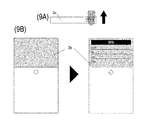
- FIG. 9 is a diagram illustrating a second example of display control in a plurality of display areas of the display 2.
- a mail icon indicating that there is one unread mail is displayed in the third display area 2c, as in FIG. 8A.
- the user flicks the mail icon displayed in the third display area 2c with the finger in the direction (the direction of the arrow in the figure) from the top surface 1C toward the back surface 1B.
- the flick direction shown in FIG. 9A is opposite to the flick direction shown in FIG. 8A.
- FIG. 9B is a diagram showing a transition of the screen displayed in the second display area 2b before and after flicking the mail icon as shown in FIG. 9A. Before the flick is performed, nothing is displayed in the second display area 2b as shown in the left diagram of FIG. 9B. Then, when the flick is performed, as shown in the right diagram of FIG. 9B, the contents of the unread mail are displayed in the second display area 2b.
- the controller 10 of the cellular phone 1 detects a flick in the direction from the top surface 1C to the back surface 1B for the mail icon displayed in the third display area 2c via the touch screen 23 provided on the top surface 1C of the cellular phone 1. To do.
- the controller 10 detects a flick of the mail icon in the direction from the top surface 1C to the back surface 1B, the controller 10 displays the content of the unread mail that is information corresponding to the mail icon in the second display area 2b on the back surface 1B side of the mobile phone 1. indicate.
- the area of the second display area 2b is smaller than that of the first display area 2a. Therefore, when displaying the contents of the unread mail in the second display area 2b, the controller 10 may reduce the size of the characters so that all the contents of the unread mail are displayed in the second display area 2b.
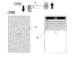
- FIG. 10 is a diagram illustrating a third example of display control in a plurality of display areas of the display 2.
- a mail icon indicating that there is one unread mail is displayed at the right end of the third display area 2c, as in FIG. 8A.
- a game icon that is an icon associated with the game application and is in the shape of the alphabet G is displayed.
- an icon that is associated with the search application and that looks like a magnifying glass is displayed.
- the user flicks the game icon displayed in the third display area 2c with the finger in the direction from the top surface 1C to the front surface 1A. Further, another user or the same user flicks the mail icon displayed in the third display area 2c in the direction from the top surface 1C to the back surface 1B with a finger.
- the screen control of the controller 10 in FIG. 10 is the same as the first example shown in FIG. 8 and the second example shown in FIG. However, the separate flicks in FIG. 10A may occur almost simultaneously.
- the controller 10 gives priority to the flick in the direction from the top surface 1C toward the front surface 1A, and displays the game screen in the first display area 2a. After that, an unread mail screen may be displayed in the second display area 2b.
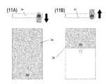
- FIG. 11 is a diagram illustrating a fourth example of display control in a plurality of display areas of the display 2.
- a camera icon corresponding to the camera application is displayed at the right end of the third display area 2c.
- the camera finder screen is displayed in the first display area 2a.
- the camera viewfinder screen is displayed in the second display area 2b.
- the mobile phone 1 Since the mobile phone 1 according to the present embodiment includes the camera 12 on the front surface 1A and the camera 13 on the back surface 1B, the image is captured by the camera 13 in the state illustrated in FIG. 11A and is captured by the camera 12 in the state illustrated in FIG. 11B. .
- the mobile phone 1 can use both the first display area 2a and the second display area 2b as a camera finder. Therefore, when the first display area 2a is used as a camera finder as shown in FIG. 11A, when a user tap is detected via the touch screen 22 on the back surface 1B side, the mobile phone 1 takes a picture. You can go.
- the mobile phone 1 uses the second display area 2b as a camera finder as shown in FIG. 11B, when a user tap is detected via the touch screen 21 on the front 1A side, You may take a picture.
- the user when the user is holding the mobile phone 1 with one hand, the user can tap the touch screen 21 or the touch screen 22 with the finger of the holding hand without using the other hand. Shooting can be performed, improving usability.
- the camera 14 is adjacent to the panel 20b (and the second display area 2b) on the back surface 1B and is provided near the center of the back surface 1B in the longitudinal direction.
- the camera 14 is positioned in front of his / her face and becomes a finder. Since the second display area 2b can be viewed for shooting, the usability is further improved.
- FIG. 12 is a diagram illustrating a first example of control according to a gesture with respect to the third display area 2c.
- FIG. 12B shows a state where the user is making a call using the telephone application.
- the user performs a swipe in the direction from left to right with respect to the third display area 2c.
- the controller 10 of the mobile phone 1 detects a swipe in the direction from left to right with respect to the third display area 2c via the touch screen 23
- the call volume is relatively increased.
- the controller 10 detects a swipe in the direction from right to left with respect to the third display area 2c via the touch screen 23
- the controller 10 relatively reduces the call volume.
- FIG. 13 is a diagram illustrating a second example of control according to a gesture for the third display region 2c.
- the mobile phone 1 In the state shown in FIG. 13A, the mobile phone 1 is in a locked state.
- An unlock icon is displayed at the center of the third display area 2c.
- the user flicks the unlock icon displayed in the third display area 2c with the finger in the direction toward the front surface 1A starting from the upper surface 1C.
- the controller 10 of the cellular phone 1 detects a flick in the direction toward the front surface 1A starting from the upper surface 1C with respect to the unlock icon, the controller 10 unlocks the cellular phone 1A and displays the home screen in the first display area 2a on the front surface 1A side. Display.
- the mobile phone 1 includes the touch screen 23 on the upper surface 1B that connects the front surface 1A and the back surface 1B of the mobile phone, and the upper surface 1C to the front surface 1A via the touch screen 23.
- a flick first gesture
- a screen corresponding to the flick is displayed in the first display area 2a on the front 1A side
- a flick second gesture
- the screen corresponding to the flick is displayed in the second display area 2b on the back surface 1B side, so that the usability of the mobile phone 1 is improved.
- the mobile phone 1 controls the display of the third display area 2c according to the attitude of the mobile phone 1. Thereby, the effective utilization of the 3rd display area 2c provided in the upper surface 1C of the housing
- the indicator area is displayed in the first display area 2a.
- the third display area 2c provided on the upper surface 1C of the mobile phone 1 is the indicator area. Therefore, the first display area 2a can be effectively used.
- a mobile phone has been described as an example of a device according to the appended claims.
- the device according to the appended claims is not limited to a mobile phone.
- the device according to the appended claims may be an electronic device other than a mobile phone. Examples of the electronic device include, but are not limited to, a tablet, a portable personal computer, a digital camera, a media player, an electronic book reader, a navigator, and a game machine.
- the display 2 is a flexible organic EL display, and the configuration including the first display area 2a, the second display area 2b, and the third display area 2c has been described as an example. It is not limited to.
- the mobile phone 1 may be configured to include separate displays (display units) and touch screens on the front surface 1A, the back surface 1B, and the top surface 1C, respectively.
- the touch screen 21, the touch screen 22, and the touch screen 23 are respectively arranged corresponding to the first display area 2a, the second display area 2b, and the third display area 2c. It is not limited to this.
- the mobile phone 1 may not include the touch screen 21 disposed on the front surface 1A and the touch screen 22 disposed on the back surface 1B, or may be disposed on the upper surface 1C.
- the third display area 2c to be provided may not be provided.
Landscapes
- Engineering & Computer Science (AREA)
- Theoretical Computer Science (AREA)
- General Engineering & Computer Science (AREA)
- Human Computer Interaction (AREA)
- Physics & Mathematics (AREA)
- General Physics & Mathematics (AREA)
- Computer Hardware Design (AREA)
- Telephone Function (AREA)
- Digital Computer Display Output (AREA)
- User Interface Of Digital Computer (AREA)
- Telephone Set Structure (AREA)
Abstract
Priority Applications (3)
| Application Number | Priority Date | Filing Date | Title |
|---|---|---|---|
| US14/768,711 US9891815B2 (en) | 2013-02-21 | 2014-02-20 | Device having touch screen and three display areas |
| JP2015501509A JP6121517B2 (ja) | 2013-02-21 | 2014-02-20 | 装置 |
| EP14753532.2A EP2960770A4 (fr) | 2013-02-21 | 2014-02-20 | Dispositif |
Applications Claiming Priority (4)
| Application Number | Priority Date | Filing Date | Title |
|---|---|---|---|
| JP2013031990 | 2013-02-21 | ||
| JP2013-031990 | 2013-02-21 | ||
| JP2013031991 | 2013-02-21 | ||
| JP2013-031991 | 2013-02-21 |
Publications (1)
| Publication Number | Publication Date |
|---|---|
| WO2014129565A1 true WO2014129565A1 (fr) | 2014-08-28 |
Family
ID=51391346
Family Applications (1)
| Application Number | Title | Priority Date | Filing Date |
|---|---|---|---|
| PCT/JP2014/054090 WO2014129565A1 (fr) | 2013-02-21 | 2014-02-20 | Dispositif |
Country Status (4)
| Country | Link |
|---|---|
| US (1) | US9891815B2 (fr) |
| EP (1) | EP2960770A4 (fr) |
| JP (1) | JP6121517B2 (fr) |
| WO (1) | WO2014129565A1 (fr) |
Cited By (3)
| Publication number | Priority date | Publication date | Assignee | Title |
|---|---|---|---|---|
| US10142547B2 (en) | 2013-11-28 | 2018-11-27 | Semiconductor Energy Laboratory Co., Ltd. | Electronic device and driving method thereof |
| WO2020021753A1 (fr) * | 2018-07-25 | 2020-01-30 | 株式会社ジャパンディスプレイ | Dispositif électronique et procédé de notification d'événement |
| JP2020035065A (ja) * | 2018-08-28 | 2020-03-05 | 京セラ株式会社 | 電子機器、制御プログラム及び表示制御方法 |
Families Citing this family (10)
| Publication number | Priority date | Publication date | Assignee | Title |
|---|---|---|---|---|
| KR101500130B1 (ko) * | 2013-09-02 | 2015-03-06 | 현대자동차주식회사 | 스티어링 휠에 설치된 차량용 제어장치 |
| KR102365393B1 (ko) * | 2014-12-11 | 2022-02-21 | 엘지전자 주식회사 | 이동단말기 및 그 제어방법 |
| US9936138B2 (en) | 2015-07-29 | 2018-04-03 | Samsung Electronics Co., Ltd. | User terminal apparatus and control method thereof |
| US11284003B2 (en) | 2015-07-29 | 2022-03-22 | Samsung Electronics Co., Ltd. | User terminal apparatus and control method thereof |
| KR20170046969A (ko) * | 2015-10-22 | 2017-05-04 | 엘지전자 주식회사 | 모바일 디바이스 및 그 제어 방법 |
| KR20170084586A (ko) * | 2016-01-12 | 2017-07-20 | 삼성전자주식회사 | 전자 장치의 플렉서블 디스플레이 및 그의 운용 방법 |
| KR102496410B1 (ko) * | 2016-03-25 | 2023-02-06 | 삼성전자 주식회사 | 전자 장치 및 전자 장치의 소리 출력 방법 |
| US9813150B1 (en) * | 2016-09-23 | 2017-11-07 | Qualcomm Incorporated | Controllable selection of light-capture devices |
| KR102682500B1 (ko) * | 2019-03-26 | 2024-07-08 | 삼성디스플레이 주식회사 | 폴더블 표시 장치와 그의 음향 제공 방법 |
| CN115052094B (zh) * | 2019-08-20 | 2024-09-17 | 深圳市大疆创新科技有限公司 | 运动相机、自拍控制方法及装置、可移动平台和存储介质 |
Citations (5)
| Publication number | Priority date | Publication date | Assignee | Title |
|---|---|---|---|---|
| WO2008086302A1 (fr) | 2007-01-07 | 2008-07-17 | Apple Inc. | Dispositif multifonction portatif, procédé, et interface graphique pour l'interprétation d'un mouvement du doigt sur un écran tactile |
| JP2010108273A (ja) * | 2008-10-30 | 2010-05-13 | Sony Corp | 情報処理装置、情報処理方法およびプログラム |
| WO2011047338A1 (fr) * | 2009-10-15 | 2011-04-21 | Qualcomm Incorporated | Procédé, système et produit programme informatique combinant une entrée gestuelle provenant de multiples écrans tactiles en une seule entrée gestuelle |
| WO2012081699A1 (fr) * | 2010-12-17 | 2012-06-21 | Necカシオモバイルコミュニケーションズ株式会社 | Dispositif de terminal mobile, procédé de commande d'affichage et programme |
| JP2013015835A (ja) * | 2011-06-30 | 2013-01-24 | Samsung Display Co Ltd | 可撓性表示パネル及び該可撓性表示パネルを備える表示装置 |
Family Cites Families (23)
| Publication number | Priority date | Publication date | Assignee | Title |
|---|---|---|---|---|
| US6035180A (en) | 1997-10-07 | 2000-03-07 | Ericsson Inc. | Communication module having selectively programmable exterior surface |
| EP1717684A3 (fr) | 1998-01-26 | 2008-01-23 | Fingerworks, Inc. | Procédé et dispositif d'intégration d'entrée manuelle |
| JP4367377B2 (ja) * | 2005-06-03 | 2009-11-18 | エプソンイメージングデバイス株式会社 | 表示装置、入力装置、及び電子機器 |
| US20070188450A1 (en) * | 2006-02-14 | 2007-08-16 | International Business Machines Corporation | Method and system for a reversible display interface mechanism |
| US20080316169A1 (en) * | 2007-06-21 | 2008-12-25 | Eli Reifman | Method circuit and system for interfacing with an electronic device |
| US7970442B2 (en) * | 2007-10-17 | 2011-06-28 | Akina Chiang | Chain-shaped foldable cellphone |
| US8947320B2 (en) * | 2008-09-08 | 2015-02-03 | Qualcomm Incorporated | Method for indicating location and direction of a graphical user interface element |
| JP5137767B2 (ja) * | 2008-09-29 | 2013-02-06 | Necパーソナルコンピュータ株式会社 | 情報処理装置 |
| KR101521219B1 (ko) * | 2008-11-10 | 2015-05-18 | 엘지전자 주식회사 | 플렉서블 디스플레이를 이용하는 휴대 단말기 및 그 제어방법 |
| KR101609162B1 (ko) * | 2008-11-13 | 2016-04-05 | 엘지전자 주식회사 | 터치 스크린을 구비한 이동 단말기 및 이를 이용한 데이터 처리 방법 |
| JP2010262557A (ja) | 2009-05-11 | 2010-11-18 | Sony Corp | 情報処理装置および方法 |
| US9152314B2 (en) * | 2009-11-30 | 2015-10-06 | Lg Electronics Inc. | Mobile terminal and controlling method thereof |
| JP5440136B2 (ja) * | 2009-12-04 | 2014-03-12 | ソニー株式会社 | 表示装置及び表示装置の制御方法 |
| US20110261002A1 (en) * | 2010-04-27 | 2011-10-27 | Microsoft Corporation | Displaying images on solid surfaces |
| US9268367B2 (en) * | 2010-10-13 | 2016-02-23 | Microsoft Technology Licensing, Llc | Use of low-power display on device |
| JP2012128668A (ja) * | 2010-12-15 | 2012-07-05 | Nikon Corp | 電子機器 |
| CN106027713B (zh) * | 2010-12-27 | 2020-07-07 | 株式会社精好 | 移动电话、声音输出装置、收听系统和收听设备 |
| US8320970B2 (en) * | 2011-02-16 | 2012-11-27 | Google Inc. | Mobile device display management |
| US9110580B2 (en) * | 2011-08-05 | 2015-08-18 | Nokia Technologies Oy | Apparatus comprising a display and a method and computer program |
| US8723824B2 (en) * | 2011-09-27 | 2014-05-13 | Apple Inc. | Electronic devices with sidewall displays |
| KR101917683B1 (ko) * | 2012-02-21 | 2018-11-13 | 엘지전자 주식회사 | 휴대 전자기기 |
| KR101899812B1 (ko) * | 2012-05-14 | 2018-09-20 | 엘지전자 주식회사 | 포터블 디바이스 및 그 제어 방법 |
| US20140132481A1 (en) * | 2012-11-09 | 2014-05-15 | Microsoft Corporation | Mobile devices with plural displays |
-
2014
- 2014-02-20 JP JP2015501509A patent/JP6121517B2/ja not_active Expired - Fee Related
- 2014-02-20 WO PCT/JP2014/054090 patent/WO2014129565A1/fr active Application Filing
- 2014-02-20 US US14/768,711 patent/US9891815B2/en not_active Expired - Fee Related
- 2014-02-20 EP EP14753532.2A patent/EP2960770A4/fr not_active Ceased
Patent Citations (5)
| Publication number | Priority date | Publication date | Assignee | Title |
|---|---|---|---|---|
| WO2008086302A1 (fr) | 2007-01-07 | 2008-07-17 | Apple Inc. | Dispositif multifonction portatif, procédé, et interface graphique pour l'interprétation d'un mouvement du doigt sur un écran tactile |
| JP2010108273A (ja) * | 2008-10-30 | 2010-05-13 | Sony Corp | 情報処理装置、情報処理方法およびプログラム |
| WO2011047338A1 (fr) * | 2009-10-15 | 2011-04-21 | Qualcomm Incorporated | Procédé, système et produit programme informatique combinant une entrée gestuelle provenant de multiples écrans tactiles en une seule entrée gestuelle |
| WO2012081699A1 (fr) * | 2010-12-17 | 2012-06-21 | Necカシオモバイルコミュニケーションズ株式会社 | Dispositif de terminal mobile, procédé de commande d'affichage et programme |
| JP2013015835A (ja) * | 2011-06-30 | 2013-01-24 | Samsung Display Co Ltd | 可撓性表示パネル及び該可撓性表示パネルを備える表示装置 |
Non-Patent Citations (1)
| Title |
|---|
| See also references of EP2960770A4 |
Cited By (7)
| Publication number | Priority date | Publication date | Assignee | Title |
|---|---|---|---|---|
| US10142547B2 (en) | 2013-11-28 | 2018-11-27 | Semiconductor Energy Laboratory Co., Ltd. | Electronic device and driving method thereof |
| JP2020024426A (ja) * | 2013-11-28 | 2020-02-13 | 株式会社半導体エネルギー研究所 | 電子機器 |
| US10771705B2 (en) | 2013-11-28 | 2020-09-08 | Semiconductor Energy Laboratory Co., Ltd. | Electronic device and driving method thereof |
| US11846963B2 (en) | 2013-11-28 | 2023-12-19 | Semiconductor Energy Laboratory Co., Ltd. | Electronic device and driving method thereof |
| WO2020021753A1 (fr) * | 2018-07-25 | 2020-01-30 | 株式会社ジャパンディスプレイ | Dispositif électronique et procédé de notification d'événement |
| JP2020035065A (ja) * | 2018-08-28 | 2020-03-05 | 京セラ株式会社 | 電子機器、制御プログラム及び表示制御方法 |
| JP7140603B2 (ja) | 2018-08-28 | 2022-09-21 | 京セラ株式会社 | 電子機器、制御プログラム及び表示制御方法 |
Also Published As
| Publication number | Publication date |
|---|---|
| JPWO2014129565A1 (ja) | 2017-02-02 |
| US20160004376A1 (en) | 2016-01-07 |
| US9891815B2 (en) | 2018-02-13 |
| EP2960770A4 (fr) | 2017-01-25 |
| EP2960770A1 (fr) | 2015-12-30 |
| JP6121517B2 (ja) | 2017-04-26 |
Similar Documents
| Publication | Publication Date | Title |
|---|---|---|
| JP6121517B2 (ja) | 装置 | |
| JP6017828B2 (ja) | 電子機器、制御方法、及び制御プログラム | |
| JP5818922B2 (ja) | 電子機器 | |
| WO2013164999A1 (fr) | Dispositif électronique, procédé de contrôle et programme de contrôle | |
| WO2013164980A1 (fr) | Appareil électronique, procédé de commande, et programme de commande | |
| JP2013131987A (ja) | 電子機器 | |
| JP2013141147A (ja) | 電子機器 | |
| WO2014003148A1 (fr) | Dispositif électronique, procédé de commande et programme de commande | |
| WO2014061679A1 (fr) | Appareil électronique portable | |
| JP6067999B2 (ja) | 電子機器、制御方法、及び制御プログラム | |
| JP5865774B2 (ja) | 電子機器、制御方法及び制御プログラム | |
| JP2015012342A (ja) | 電子機器 | |
| JP2013232853A (ja) | 電子機器、制御方法、及び制御プログラム | |
| JP6242040B2 (ja) | 電子機器、制御方法、及び制御プログラム | |
| JP6099320B2 (ja) | 電子機器、制御方法及び制御プログラム | |
| JP2014082674A (ja) | 電子機器、制御方法及び制御プログラム | |
| JP2014011512A (ja) | 電子機器、制御方法、及び制御プログラム | |
| JP2013236139A (ja) | 電子機器、制御方法、及び制御プログラム | |
| JP6017829B2 (ja) | 電子機器 | |
| JP2014011511A (ja) | 電子機器、制御方法、及び制御プログラム | |
| JP6110078B2 (ja) | 電子機器、制御方法、及び制御プログラム | |
| JP2015050703A (ja) | 電子機器 | |
| JP2013141213A (ja) | 電子機器 | |
| JP2014007444A (ja) | 電子機器、制御方法及び制御プログラム | |
| JP6125561B2 (ja) | 携帯端末装置、プログラムおよび音出力制御方法 |
Legal Events
| Date | Code | Title | Description |
|---|---|---|---|
| 121 | Ep: the epo has been informed by wipo that ep was designated in this application |
Ref document number: 14753532 Country of ref document: EP Kind code of ref document: A1 |
|
| ENP | Entry into the national phase |
Ref document number: 2015501509 Country of ref document: JP Kind code of ref document: A |
|
| WWE | Wipo information: entry into national phase |
Ref document number: 2014753532 Country of ref document: EP |
|
| WWE | Wipo information: entry into national phase |
Ref document number: 14768711 Country of ref document: US |
|
| NENP | Non-entry into the national phase |
Ref country code: DE |