WO2014129167A1 - 塗布膜除去装置 - Google Patents
塗布膜除去装置 Download PDFInfo
- Publication number
- WO2014129167A1 WO2014129167A1 PCT/JP2014/000792 JP2014000792W WO2014129167A1 WO 2014129167 A1 WO2014129167 A1 WO 2014129167A1 JP 2014000792 W JP2014000792 W JP 2014000792W WO 2014129167 A1 WO2014129167 A1 WO 2014129167A1
- Authority
- WO
- WIPO (PCT)
- Prior art keywords
- coating film
- removal liquid
- removal
- liquid
- supply means
- Prior art date
- Legal status (The legal status is an assumption and is not a legal conclusion. Google has not performed a legal analysis and makes no representation as to the accuracy of the status listed.)
- Ceased
Links
Images




Classifications
-
- B—PERFORMING OPERATIONS; TRANSPORTING
- B08—CLEANING
- B08B—CLEANING IN GENERAL; PREVENTION OF FOULING IN GENERAL
- B08B3/00—Cleaning by methods involving the use or presence of liquid or steam
- B08B3/04—Cleaning involving contact with liquid
- B08B3/10—Cleaning involving contact with liquid with additional treatment of the liquid or of the object being cleaned, e.g. by heat, by electricity or by vibration
- B08B3/12—Cleaning involving contact with liquid with additional treatment of the liquid or of the object being cleaned, e.g. by heat, by electricity or by vibration by sonic or ultrasonic vibrations
-
- B—PERFORMING OPERATIONS; TRANSPORTING
- B08—CLEANING
- B08B—CLEANING IN GENERAL; PREVENTION OF FOULING IN GENERAL
- B08B3/00—Cleaning by methods involving the use or presence of liquid or steam
- B08B3/02—Cleaning by the force of jets or sprays
- B08B3/024—Cleaning by means of spray elements moving over the surface to be cleaned
-
- B—PERFORMING OPERATIONS; TRANSPORTING
- B08—CLEANING
- B08B—CLEANING IN GENERAL; PREVENTION OF FOULING IN GENERAL
- B08B3/00—Cleaning by methods involving the use or presence of liquid or steam
- B08B3/04—Cleaning involving contact with liquid
- B08B3/10—Cleaning involving contact with liquid with additional treatment of the liquid or of the object being cleaned, e.g. by heat, by electricity or by vibration
-
- B—PERFORMING OPERATIONS; TRANSPORTING
- B08—CLEANING
- B08B—CLEANING IN GENERAL; PREVENTION OF FOULING IN GENERAL
- B08B5/00—Cleaning by methods involving the use of air flow or gas flow
- B08B5/02—Cleaning by the force of jets, e.g. blowing-out cavities
-
- B—PERFORMING OPERATIONS; TRANSPORTING
- B08—CLEANING
- B08B—CLEANING IN GENERAL; PREVENTION OF FOULING IN GENERAL
- B08B5/00—Cleaning by methods involving the use of air flow or gas flow
- B08B5/02—Cleaning by the force of jets, e.g. blowing-out cavities
- B08B5/023—Cleaning travelling work
- B08B5/026—Cleaning moving webs
-
- B—PERFORMING OPERATIONS; TRANSPORTING
- B32—LAYERED PRODUCTS
- B32B—LAYERED PRODUCTS, i.e. PRODUCTS BUILT-UP OF STRATA OF FLAT OR NON-FLAT, e.g. CELLULAR OR HONEYCOMB, FORM
- B32B38/00—Ancillary operations in connection with laminating processes
- B32B38/10—Removing layers, or parts of layers, mechanically or chemically
-
- G—PHYSICS
- G03—PHOTOGRAPHY; CINEMATOGRAPHY; ANALOGOUS TECHNIQUES USING WAVES OTHER THAN OPTICAL WAVES; ELECTROGRAPHY; HOLOGRAPHY
- G03F—PHOTOMECHANICAL PRODUCTION OF TEXTURED OR PATTERNED SURFACES, e.g. FOR PRINTING, FOR PROCESSING OF SEMICONDUCTOR DEVICES; MATERIALS THEREFOR; ORIGINALS THEREFOR; APPARATUS SPECIALLY ADAPTED THEREFOR
- G03F7/00—Photomechanical, e.g. photolithographic, production of textured or patterned surfaces, e.g. printing surfaces; Materials therefor, e.g. comprising photoresists; Apparatus specially adapted therefor
- G03F7/0005—Production of optical devices or components in so far as characterised by the lithographic processes or materials used therefor
-
- H—ELECTRICITY
- H10—SEMICONDUCTOR DEVICES; ELECTRIC SOLID-STATE DEVICES NOT OTHERWISE PROVIDED FOR
- H10K—ORGANIC ELECTRIC SOLID-STATE DEVICES
- H10K71/00—Manufacture or treatment specially adapted for the organic devices covered by this subclass
-
- H—ELECTRICITY
- H10—SEMICONDUCTOR DEVICES; ELECTRIC SOLID-STATE DEVICES NOT OTHERWISE PROVIDED FOR
- H10K—ORGANIC ELECTRIC SOLID-STATE DEVICES
- H10K71/00—Manufacture or treatment specially adapted for the organic devices covered by this subclass
- H10K71/10—Deposition of organic active material
- H10K71/12—Deposition of organic active material using liquid deposition, e.g. spin coating
- H10K71/13—Deposition of organic active material using liquid deposition, e.g. spin coating using printing techniques, e.g. ink-jet printing or screen printing
-
- H—ELECTRICITY
- H10—SEMICONDUCTOR DEVICES; ELECTRIC SOLID-STATE DEVICES NOT OTHERWISE PROVIDED FOR
- H10K—ORGANIC ELECTRIC SOLID-STATE DEVICES
- H10K71/00—Manufacture or treatment specially adapted for the organic devices covered by this subclass
- H10K71/10—Deposition of organic active material
- H10K71/12—Deposition of organic active material using liquid deposition, e.g. spin coating
- H10K71/13—Deposition of organic active material using liquid deposition, e.g. spin coating using printing techniques, e.g. ink-jet printing or screen printing
- H10K71/135—Deposition of organic active material using liquid deposition, e.g. spin coating using printing techniques, e.g. ink-jet printing or screen printing using ink-jet printing
Definitions
- the present invention relates to a coating film removing apparatus that selectively removes a coating film in a manufacturing process of a polymer organic EL display panel or the like.
- the organic EL element recombines injected electrons and holes by applying a voltage to the conductive organic light-emitting medium layer, and the organic light-emitting layer included in the organic light-emitting medium layer upon this recombination
- the organic light emitting material constituting the light is made to emit light.
- a first electrode and a second electrode are provided on both sides of the organic light emitting medium layer in order to apply a voltage to the organic light emitting layer and extract light to the outside.
- This organic EL element is configured by sequentially laminating a first electrode, an organic light emitting layer, and a second electrode (counter electrode) on a transparent substrate, and the first electrode formed on the substrate is an anode, on the organic light emitting layer.
- the counter electrode formed on is used as a cathode.
- a hole transport layer and a hole injection layer are provided between the anode and the organic light emitting layer, or an electron transport layer and an electron injection are provided between the organic light emitting layer and the cathode.
- the layers are appropriately selected and configured as an organic EL element.
- a laminated structure in which the organic light emitting layer and the hole transport layer, the hole injection layer, the electron transport layer, and the electron injection layer are combined is called an organic light emitting medium layer.
- Substances (light-emitting medium materials) constituting and functioning the organic light-emitting medium layer are generally low-molecular compounds, and each layer has a thickness of about 1 nm to 100 nm and is laminated by a vacuum evaporation method such as a resistance heating method.
- a vacuum evaporation method such as a resistance heating method.
- the luminescent medium layer a polymer obtained by dissolving a low-molecular luminescent dye in a polymer such as polystyrene, polymethyl methacrylate, polyvinyl carbazole, or a polymer such as polyphenylene vinylene derivative (PPV) or polyalkylfluorene derivative (PAF).
- a light emitter is used. Since these polymer materials can form a coating film by a wet method such as a coating method or a printing method by dissolving or dispersing in a solvent, compared with the organic EL element using the above-described low molecular weight material, There is an advantage that a film can be formed under atmospheric pressure and the equipment cost is low.
- a coating method includes a spin coating method, a bar coating method, a slit coating method, a dip coating method, and the like. If high-definition patterning is not particularly necessary, the coating is simple and uniform. The method is effective, and is effective for forming a common layer that does not need to be applied separately for each pixel, such as the hole transport layer and the hole injection layer. On the other hand, when high-definition patterning or RGB three-color coating is required, thin film formation by printing methods such as an intaglio printing method, a relief printing method, a planographic printing method, a screen printing method, and an ink jet method is most effective.
- the sealing which is a step after forming the cathode on the organic light emitting medium layer.
- the cathode In the state where the cathode is formed on the organic light emitting medium layer, it is particularly susceptible to moisture (water vapor) and oxygen, and the non-light emitting defect referred to as a dark spot occurs due to the deterioration of the light emission characteristics and the deterioration of the metal electrode. . Therefore, it is common to seal using a sealing glass substrate in which a hygroscopic agent is disposed in a portion facing the display region in a chamber in which moisture and oxygen are suppressed to the limit.
- the sealing glass substrate When the sealing glass substrate is formed on the substrate on which the organic light emitting medium layer is formed, there is a certain bonding width (sealing space) for bonding the sealing glass substrate and the substrate on which the organic light emitting medium layer is formed. Necessary. At that time, in order to sufficiently obtain the sealing performance, it is desirable that the organic material constituting the organic light emitting medium layer is not applied to the sealing space. However, when the hole transport layer and the hole injection layer are formed by a coating method, the organic material may be formed even in the sealing space, and there is a problem that the sealing performance is impaired. .
- an object of the present invention is to provide a coating film removing apparatus capable of easily and accurately removing a coating film applied to a film formation unnecessary region in a manufacturing process of a polymer organic EL panel or the like. Yes.
- One aspect of the present invention is a removal liquid supply unit that discharges a removal liquid for removing a coating film only to a coating film removal portion that is a part of a coating film on a substrate (for example, the substrate 1 shown in FIG. 3).
- the removal liquid discharge port and the removal liquid recovery port of the removal liquid recovery means facing the coating film removal section, a predetermined amount of the removal liquid is supplied from the removal liquid supply means only to the coating film removal section.
- the coating film removing apparatus includes a water-repellent outer shell portion (for example, the water-repellent outer shell portion 11 shown in FIG. 7) that has been subjected to a water-repellent treatment so as to include the discharge port and the recovery port. Also good.
- the water contact angle of the water repellent shell portion may be 90 degrees or more.
- the above-described coating film removing apparatus recovers the removing liquid by the removing liquid collecting means after a predetermined holding time has elapsed after the removing liquid is discharged only to the coating film removing unit. It may be.
- the coating film removing apparatus includes an ultrasonic vibration applying unit (for example, ultrasonic vibration applying unit 8 shown in FIG. 4) that applies ultrasonic vibration to the removal liquid discharged to the coating film removing unit.
- the temperature of the removal liquid discharged to the coating film removing unit may be 30 ° C. or higher and 40 ° C. or lower.
- the coating film removing apparatus further includes a gas supply unit (for example, an air supply unit 6 shown in FIG. 3) that discharges gas to an arbitrary position on the substrate, and the coating by the removal liquid supply unit. The discharge liquid is prevented from flowing out of the coating film removal section from the start of discharge of the removal liquid to the film removal section until the removal of the removal liquid by the removal liquid collection means ends.
- Gas may be discharged by the gas supply means.
- the gas supply means may be arranged so as to surround the water repellent outer shell.
- the gas supply unit may discharge nitrogen gas as the gas.
- the coating film removing apparatus is configured to horizontally move the removing liquid supply unit and the removing liquid collecting unit to a position facing the coating film removing unit to discharge and collect the removing liquid. Good.
- Another aspect of the present invention is a removing liquid that discharges a removing liquid for removing the coating film only to a coating film removing portion that is a part of the coating film on the substrate (for example, the substrate 1 shown in FIG. 3).
- the removal liquid is collected after a predetermined time has elapsed since the removal liquid was discharged to the coating film removal section by the supply means (for example, the removal liquid supply means 4 shown in FIG. 3) and the removal liquid supply means. From the start of discharge of the removal liquid by the removal liquid collection means (for example, the removal liquid collection means 5 shown in FIG. 3) and the removal liquid supply means until the removal of the removal liquid by the removal liquid collection means ends During this time, gas supply means (for example, air supply means 6 shown in FIG.
- a horizontal moving part for example, coating film removing means (vertical) 3a, coating film removing means (horizontal) 3b shown in FIG. 1) formed integrally with a gas discharge port of the gas supply means and movable horizontally;
- the gas discharge port is disposed so as to surround the removal liquid discharge port and the removal liquid recovery port.
- the coating film removing apparatus is disposed outside the removal liquid discharge port and the removal liquid recovery port, and the water repellent outer portion suppresses the wetting and spreading of the removal liquid to the outside of the coating film removal unit.
- the water-repellent outer shell portion 11 shown in FIG. 4 may be further provided, and the gas discharge port may be disposed so as to further surround the water-repellent outer shell portion.
- the coating film removing portion which is a part of the coating film on the substrate can be easily and accurately removed. Therefore, for example, the coating film such as the outer peripheral portion of the organic light emitting pixel can be reliably removed. As a result, the sealing performance can be improved and a polymer organic EL panel free from light emitting pixel defects can be easily obtained.
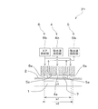
- FIG. 2 is a cross-sectional view of the removal processing unit according to the first embodiment of the present invention, which is a cross-sectional view taken along the line AA in FIG.
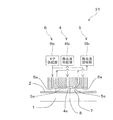
- FIG. 4 is a cross-sectional view of a removal processing unit according to a second embodiment of the present invention, which is a cross-sectional view taken along the line AA in FIG. It is sectional drawing which shows an example of the coating film removal means which has an ultrasonic vibration application means based on 2nd Embodiment of this invention.
- FIG. 1 is a schematic configuration diagram showing an example of coating film removing apparatuses 100 and 101 to which the present invention is applied.
- the coating film removing apparatuses 100 and 101 are apparatuses that remove a coating film removing unit that is a part of the coating film on the substrate. That is, this is an apparatus for removing a coating film removing portion applied to a film formation unnecessary region where coating of a coating film is unnecessary on the substrate.
- reference numeral 1 denotes a substrate on which a coating film is to be removed
- reference numeral 2 denotes a coating film applied on the substrate
- reference numeral 10 denotes a necessary component on the substrate 1 out of the coating film 2 applied onto the substrate 1.
- the coating film portion other than the necessary film formation region 10 is a film formation unnecessary region where the coating film removal unit is located.
- the coating film removing apparatus 100 includes a coating film removing unit 3 and a stage 9 that holds the substrate 1 to be coated film removed by suction.
- the coating film removing means 3 is a coating film removing means (longitudinal) 3a that moves along the left-right direction of the stage 9 in FIG. 1 and removes the coating film in units of the vertical direction (vertical direction in FIG. 1) with respect to the substrate 1.
- a coating film removing means (horizontal) 3 b that moves in the vertical direction of the stage 9 and removes the coating film in units in the lateral direction of the substrate 1 is provided.
- the coating film removing means (vertical) 3a is arranged along the vertical direction of the stage 9 so as to straddle the substrate 1 sucked and held on the stage 9, and the gap with the substrate 1 becomes a predetermined value. Be placed.
- the coating film removing means (vertical) 3a moves in the left-right direction using, for example, a guide (not shown) arranged along the left-right direction on the upper and lower sides of the stage 9 as a guide. Thereby, for example, as shown in FIG. 2, the coating film removing means (vertical) 3 a scans in the left-right direction of the substrate 1.
- the coating film removing means (horizontal) 3b is arranged at an angle shifted by 90 degrees from the coating film removing means (vertical) 3a. That is, they are arranged along the left-right direction of the stage 9 so as to straddle the substrate 1 held by suction on the stage 9 and arranged so that the gap with the substrate 1 becomes a predetermined value.
- the coating film removing means (horizontal) 3b moves in the vertical direction using, for example, a guide (not shown) arranged along the vertical direction on the left and right sides of the stage 9 as a guide.
- the coating film removing means (horizontal) 3b scans the substrate 1 in the vertical direction. That is, the coating film removing units 3a and 3b only need to be movable in two directions by setting, for example, orthogonal coordinates in the direction in which the necessary film forming regions 10 are arranged.
- the coating film removing means (vertical) 3a and the coating film removing means (horizontal) 3b are moved by a driving device (not shown).
- the removal processing unit is disposed on the coating film removing means (vertical) 3a and the coating film removing means (horizontal) 3b so as to face the film formation unnecessary area, which is an area excluding the necessary film formation area 10 on the substrate 1, respectively. 31 is provided. That is, as shown in FIG. 1C, the film formation unnecessary regions extending in the left-right direction of the substrate 1 are e1, e2, e3 in order from the top, and the film formation unnecessary regions extending in the vertical direction of the substrate 1 are from the left.
- the coating film removing means (vertical) 3a has a removal processing unit at positions corresponding to the film formation unnecessary regions e1 to e3 as shown in FIG. 31 is arranged.
- the removal processing unit 31 is arranged at a position corresponding to each of the film formation unnecessary regions e4 to e7 in the coating film removing unit (horizontal) 3b.
- Each removal processing unit 31 has the same configuration.
- FIG. 3 is a cross-sectional view taken along the line AA of the removal processing unit 31 shown in FIG.
- the removal processing unit 31 includes a removal liquid supply unit 4, a removal liquid collection unit 5, and an air supply unit 6.
- the removal liquid supply means 4 includes a removal liquid supply port 4a and a removal liquid supply unit 4b that supplies the removal liquid 7 to the removal liquid supply port 4a.
- the removal liquid supply port 4a is located in the vicinity of the center of the removal processing unit 31 so as to face a film formation unnecessary region (for example, e1 in FIG. 3) on the substrate 1. Be placed.
- the removal liquid 7 for removing the coating film is supplied to the removal liquid supply port 4a by the removal liquid supply unit 4b and removed from the opening end of the removal liquid supply port 4a on the substrate 1 side.
- the liquid 7 is discharged onto the substrate 1.
- the removal liquid supply unit 4b is configured by a syringe pump or the like capable of quantitative discharge, and discharges a predetermined amount of the removal liquid 7 onto the substrate 1 through the removal liquid supply port 4a.
- the removal liquid collection means 5 includes a removal liquid collection port 5 a and a removal liquid collection unit 5 b disposed so as to face a film formation unnecessary region on the substrate 1.
- a plurality of removal liquid recovery ports 5a are arranged so as to surround the removal liquid supply port 4a squarely, for example.
- the removal liquid recovery port 5a has an opening end facing the substrate 1 curved toward the removal liquid supply port 4a. Note that the cross-sectional shape of the removal processing unit 31, in particular, the shape and positional relationship of the removal liquid supply port 4 a and the removal collection port 5 a may not be limited to this.
- the removal liquid recovery unit 5b includes a suction device such as an ejector tank. By operating the removal liquid recovery unit 5b, the removal liquid 7 on the substrate 1 is recovered through the removal liquid recovery port 5a. Collected in part 5b.
- the air supply means 6 includes an air supply port 6 a and an air supply unit 6 b disposed so as to face a film formation unnecessary region on the substrate 1.
- the air supply port 6a is formed, for example, in a shape that surrounds the periphery of the removal liquid recovery port 5a squarely. And air is sprayed on the board
- the air supply unit 6 corresponds to the “gas supply unit” of the present application
- the air supply port 6a corresponds to the “gas supply port” of the present application
- the air supply unit 6b corresponds to the “gas supply unit” of the present application
- Air corresponds to the “gas” of the present application.
- the width w1 between the air supply ports 6a along the longitudinal direction of the coating film removing means (longitudinal) 3a is equal to the film formation unnecessary region e1 along the longitudinal direction of the coating film removing means (longitudinal) 3a. Is set slightly shorter than the width w2.
- the length of the air supply port 6a along the short direction of the coating film removing means (vertical) 3a is not limited.
- the removal processing unit 31 having such a configuration is disposed in the coating film removing means (vertical) 3a together with the intervals of the film formation unnecessary regions e1, e2, e3 shown in FIG.
- the removal liquid supply means 4 By operating the removal liquid supply means 4, the removal liquid collection means 5, and the air supply means 6 in a state where the removal means 31a is positioned so that the removal processing section 31 faces the film formation unnecessary areas e1 to e3.
- the removal liquid 7 can be discharged to the film formation unnecessary area and the removal liquid 7 can be recovered while preventing the removal liquid from flowing outside the film formation unnecessary area.
- the coating film removing means (horizontal) 3b for example, as shown in FIG. 1C, the removal processing unit 31 is disposed in the coating film removing means (horizontal) 3b together with the interval between the film formation unnecessary regions e4 to e7. do it.
- the removal liquid supply unit 4b, the removal liquid recovery unit 5b, and the air supply unit 6b may be provided in the main body of the coating film removing unit (vertical) 3a or separate from the coating film removing unit (vertical) 3a.
- the removal liquid supply unit 4b and the removal liquid supply port 4a may be connected via a deformable removal liquid supply tube.
- the removal liquid recovery may be performed via a deformable removal liquid collection tube.
- the part 5b and the removal liquid recovery port 5a may be connected, and the air supply unit 6b and the air supply port 6a may be connected via a deformable air supply tube.
- any one or two of 4b, the removal liquid recovery unit 5b, and the air supply unit 6b may be provided in the coating film removing means (vertical) 3a and the coating film removing means (horizontal) 3b.
- the arrangement of the removal liquid supply port 4a, the removal liquid recovery port 5a, and the air supply port 6a in the removal processing unit 31 is not limited to the above.
- a plurality of removal liquid supply ports 4a may be provided, and the removal liquid collection ports 5a may be arranged in a circle or randomly.
- the air supply port 6a is formed so as to surround the removal liquid supply port 4a and the removal liquid collection port 5a in a square shape, but may be formed so as to surround in a circular shape, and a plurality of air supply ports 6a are provided.
- the air supply port 6a may be randomly arranged at a position facing the vicinity of the boundary in the film formation unnecessary region.
- the removal liquid supply port 4a and the removal liquid recovery port 5a are within the range surrounded by the air curtain by the air supply means 6, and the removal liquid 7 discharged by the removal liquid supply port 4a is outside the film formation unnecessary region. It is only necessary to avoid scattering and moving.
- the removal processing unit 31 may be movably disposed on the coating film removing unit (vertical) 3a and the coating film removing unit (horizontal) 3b. In this way, even when a removal process is performed on a plurality of substrates having different widths and intervals of the film formation unnecessary regions, the removal process can be performed while the position of the removal processing unit 31 is shifted or removed. After adjusting the arrangement position of the processing unit 31 in accordance with the interval between the film formation unnecessary regions, it is possible to appropriately cope with the problem by starting the removal process.
- a coating film removing unit (vertical) 3 a is disposed so as to face the coating film 2 formed on the substrate 1, and the coating film removing unit (vertical) 3 a and the coating film are disposed.
- the removal liquid 7 is discharged from the removal liquid supply unit 4b to the substrate 1 through the removal liquid supply port 4a so that a fixed amount of the removal liquid 7 is held between the substrate 2 and the substrate 1 on which the film 2 is formed. Is held for a predetermined time. This predetermined time is sufficient for the coating film 2 to be dissolved or peeled off by the removal liquid 7.
- the substrate 1 and the coating film removing means (vertical) 3a are arranged close to each other, and a certain amount of the removing liquid 7 is discharged. Therefore, the gap between the substrate 1 and the coating film removing means (longitudinal) 3a takes into consideration the characteristics such as the amount and viscosity of the removing liquid 7, the discharge speed of the removing liquid 7 by the removing liquid supply means 4, and the like. Thus, by setting a gap between the substrate 1 and the coating film removing means (vertical) 3a, the removal liquid 7 can be held between the substrate 1 and the coating film removing means (vertical) 3a.
- the coating film removing means (vertical )
- the removal liquid 7 mixed with the coating film 2 between 3a and the substrate 1 is recovered by the removal liquid recovery means 5 and discharged. That is, the removal liquid recovery part 5b is operated, and the removal liquid 7 on the substrate 1 is recovered through the removal liquid recovery port 5a.
- the air supply means 6 is operated until the recovery of the removal liquid 7 on the substrate 1 is completed after the discharge of the removal liquid 7 by the removal liquid supply means 4 is started. Then, air is discharged onto the substrate 1.
- the air supply port 6a is disposed around the removal liquid supply port 4a and the removal liquid recovery port 5a, so that the substrate 1 is driven by the air discharged from the air supply port 6a. It is possible to avoid the removal liquid 7 ejected above from scattering or flowing outside the film formation unnecessary region, that is, the coating film 2 in the necessary film formation region 10 is unintentionally removed. Can be avoided. Therefore, only the coating film 2 in the film formation unnecessary region can be removed.
- the air supplied by the air supply means 6 considers the influence on the characteristics of the organic material used for the coating film 2 and has a reactivity with nitrogen gas or inert gas (that is, with the organic material used). Low gas). In short, a gas having low reactivity with the organic material to be used may be supplied from the air supply means 6.
- ultrasonic vibration may be applied to the removing liquid 7 in order to improve the removability of the coating film 2. That is, as shown in FIG. 4, for example, an ultrasonic vibration applying means 8 is provided at the opening end of the removal liquid supply port 4a, and the ultrasonic vibration applying means 8 is operated to vibrate the removal liquid 7. You can do it. Further, by setting the temperature of the removal liquid 7 to 30 ° C. or more and 40 ° C. or less, the coating film 2 can be efficiently dissolved, and the processing time can be shortened and the coating film 2 can be removed more reliably. it can. In the above embodiment, as shown in FIG.
- the coating film removing means (vertical) 3a and the coating film removing means (horizontal) 3b arranged at an angle of 90 degrees are scanned one by one.
- the present invention is not limited to this.
- the coating film removing unit 3 may be configured to be movable in the vertical direction and the horizontal direction.
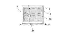
- a guide rail 21 is disposed along the vertical direction of the substrate 1 so as to straddle the substrate 1, and the coating film removing means 3 is movably disposed on the guide rail 21.
- a guide extending in the left-right direction is provided on the upper and lower sides of the substrate 1, and the guide rail 21 is arranged to be movable in the left-right direction using this guide as a guide.
- the coating film removing means 3 is moved in the vertical direction and the left-right direction with respect to the substrate 1.
- the coating liquid 7 is supplied and recovered by the coating film removing means 3 over the entire surface of the substrate 1.
- one removal processing unit 31 may be provided in the coating film removing unit 3. Further, when the removal process of the coating film 2 is performed on a plurality of film formation unnecessary regions by one removal processing unit 31, the width w1 of the removal processing unit 31 is significantly narrower than the width of the film formation unnecessary region. The width w1 of the removal processing unit 31 may not be an appropriate width with respect to the film formation unnecessary region. In this case, for example, in FIG. 6, the coating film removing means 3 is moved not only in the vertical direction but also in the horizontal direction so that the coating film is removed by moving in the vertical direction while performing fine adjustment in the horizontal direction. You can do it.
- the removal liquid supply means 4, the removal liquid collection means 5, the supply timing of the removal liquid 7 by the air supply means 6, the recovery timing of the removal liquid 7, and the control of the air supply timing are controlled by a host device (not shown).
- the host device also controls the coating film removing means (vertical) 3a, the coating film removing means (horizontal) 3b, and the drive device that drives the coating film removing means 3, and the coating film removing means (vertical) 3a and the coating film are also controlled.
- the coating film removal apparatus 101 has substantially the same configuration as the coating film removal apparatus 100 according to the first embodiment, but the coating film removal apparatus is provided with a removal processing unit 32. Different from the device 100. More specifically, the coating film removal apparatus 101 is different from the coating film removal apparatus 100 in that the removal processing unit 31 according to the first embodiment includes a removal processing unit 32 provided with the water-repellent outer shell 11. In other words, the coating film removal apparatus 101 is a coating film removal apparatus in which the removal processing unit 31 included in the coating film removal apparatus 100 is replaced with the removal processing unit 32. Therefore, only the water repellent outer shell 11 will be described, and the description of the other components will be omitted.
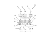
- FIG. 7 is a cross-sectional view of the removal processing unit according to the second embodiment of the present invention, which is a cross-sectional view taken along line AA of FIG.
- the removal processing unit 32 is obtained by providing the water repellent outer shell part 11 in the removal processing unit 31 according to the first embodiment.
- the water repellent shell 11 has a shape that surrounds the periphery of the removal liquid supply port 4a and the removal liquid recovery port 5a in a square shape, and is disposed inside the water repellent shell 11 by being formed in this shape.
- the removal liquid 7 discharged from the removal liquid supply port 4a is prevented from spreading outward.
- the water repellent outer shell 11 is formed so as to include the removal liquid supply port 4a and the removal liquid recovery port 5a.
- the water repellent outline 11 may be disposed so as to surround the removal liquid supply port 4a and the removal liquid collection port 5a as described above, for example, in a circular shape. It may be arranged as follows. Further, the water repellent outer portion 11 may be randomly arranged at a position facing the vicinity of the boundary in the film formation unnecessary region. In short, the removal liquid supply port 4a and the removal liquid recovery port 5a are within the range surrounded by the water repellent outer shell part 11, and the water repellent water repellent of the water repellent outer shell part 11 is discharged from the removal liquid supply port 4a. It is only necessary that 7 can be prevented from moving outside the film formation unnecessary region.
- the water contact angle of the water repellent outer shell 11 is preferably 90 degrees or more.
- the air supply port 6a may be disposed so as to surround the removal liquid supply port 4a, the removal liquid recovery port 5a, and the water repellent outer shell 11 in a square shape, or may be enclosed in a circular shape. It may be arranged as follows. A plurality of air supply ports 6a may be provided, and the air supply ports 6a may be randomly arranged at positions facing the vicinity of the boundary in the film formation unnecessary region. In short, the removal liquid supply port 4a, the removal liquid collection port 5a, and the water repellent outer shell 11 are within the range surrounded by the air curtain by the air supply means 6, and the removal liquid 7 discharged by the removal liquid supply port 4a is It suffices if it is possible to avoid scattering and movement outside the film formation unnecessary region.
- the water-repellent outer shell 11 subjected to the water-repellent treatment is disposed around the removal liquid supply port 4a and the removal liquid collection port 5a. Therefore, it is possible to suppress the removal liquid 7 discharged onto the substrate 1 from spreading out to the outside of the film formation unnecessary region due to the water repellency of the water repellent outline 11.
- the air supply port 6a is disposed around the removal liquid supply port 4a and the removal liquid recovery port 5a, so that the substrate 1 is driven by the air discharged from the air supply port 6a. It is possible to avoid the removal liquid 7 ejected above from being scattered or flowing outside the film formation unnecessary region.
- the coating film 2 in the necessary film forming region 10 is unintentionally removed together with the effect of suppressing the wetting and spreading of the removing liquid 7 by the water repellent outer shell 11. Can be avoided. Therefore, it is possible to more reliably remove only the coating film 2 in the film formation unnecessary region.
- the operation and others of the coating film removal apparatus 101 according to the present embodiment are the same as the operation and others of the coating film removal apparatus 100 according to the first embodiment. That is, for the operation and the like of the coating film removing apparatus 101, the items described in the operation and the like of the coating film removing apparatus 100 can be applied as they are. Therefore, detailed description of the operation and the like of the coating film removing apparatus 101 is omitted.
- ultrasonic vibration may be applied to the removal liquid 7 ejected for improving the removability of the coating film 2. That is, as shown in FIG. 8, for example, an ultrasonic vibration applying means 8 is provided at the end of the opening of the removal liquid supply port 4a, and the ultrasonic vibration applying means 8 is operated to vibrate the removing liquid 7. You can do it.
- Example 1 As an example of coating film removal using the coating film removing apparatuses 100 and 101 according to the embodiment of the present invention, an organic material for forming a hole transport layer on a substrate in a hole transport layer forming process of an organic EL display Is applied with a slit die, and the unnecessary coating film on the outer periphery of the light emitting region, which is a necessary film forming region, is removed.
- Poly (3,4) ethylenedioxythiophene / polystyrene sulfonic acid (PEDOT / PSS) was used as the hole transport layer material to be applied, and pure water was used as the removal liquid.
- alkali-free glass OA-10 Alkali-free glass 120mm x 120mm x 0.7mm as the substrate, and selectively removes unnecessary coating film on the outside of the four sides of the outer periphery when the required film formation area is 50mm x 50mm. Tried to do. First, the hole transport material was applied to a cleaned substrate in the range of 100 mm ⁇ 100 mm with a slit die, and then dried at 180 ° C. for 1 hour under reduced pressure to obtain a 100 nm coating film.
- OA-10 Alkali-free glass
- the outer sides of the outer periphery of the four sides are removed liquid supply means 4 and removed liquid recovery means 5 as shown in FIGS.
- the coating film was selectively removed by the coating film removing means 3 having The gap between the substrate and the lower end of the coating film removal means 3 is 1 mm, and a syringe pump is used as the removal liquid supply unit 4b of the removal liquid supply means 4 to enable quantitative discharge.
- the amount of the removal liquid retained in the gap was defined.
- the removal liquid recovery means 5 took out the exhaust gas, and was held between the substrate and the coating film removal means 3 for a desired time, and the removal liquid in which the hole transport material was dissolved was recovered.
- the coating film is generally removed if the holding time is 30 seconds or more, the same operation is repeated once more to reliably remove the material remaining without being recovered, Better cleanliness can be expected.
- the scanning by the coating film removing means 3 is repeated, the scanning direction is further switched by 90 degrees, and unnecessary coating films in the film formation unnecessary areas outside the four outer sides of the necessary film formation area are sequentially processed, whereby 50 mm ⁇ 50 mm A state in which there is no remaining coating film on the outer periphery of the necessary film formation region is obtained, and in the coating film removing means 3, air is supplied by the air supply port 6a disposed outside the removal solution supply port 4a and the removal solution collection port 5a. The desired state could be confirmed without scattering of the removal liquid to the necessary film formation region.
- the coating film removing apparatus 101 according to the second embodiment that is, the coating film removing apparatus including the removal processing unit 32 including the water repellent outline 11
- the suppression of wetting and spreading of the removal liquid to the required film formation region was confirmed by the water repellency of the water repellent outer shell portion 11 disposed outside the removal liquid supply port 4a and the removal liquid collection port 5a.
- the water repellent shell 11 was subjected to nickel-Teflon (registered trademark) plating treatment on the surface facing the coating film to obtain water repellency with a water contact angle of 90 degrees.
- Nickel Teflon (registered trademark) plating treatment means that Teflon (registered trademark) is combined in a nickel plating film.
- Example 2 Next, in each condition in Example 1, the temperature condition of the removal liquid was 24 ° C., but the temperature condition of the removal liquid was changed from 24 ° C. to 30 ° C. to remove the coating film in the same manner. went.
- the other conditions except the temperature condition of the removal liquid were the same as the conditions in Example 1.
- the temperature of the removal liquid is 24 ° C.
- the coating film can be removed in approximately 30 seconds
- the temperature of the removal liquid is 30 ° C.
- the time required for removing the coating film is approximately 20 seconds. It can be shortened and the removal performance is improved.
- the temperature of the removal liquid was further increased, it was confirmed that the removal performance was further improved.
- the temperature is higher than 40 ° C., the difference in removal performance improvement is not large and the effect is diminished.
- Example 3 each condition in Example 2, that is, the temperature condition of the removal liquid is 30 ° C., while applying ultrasonic vibration to the removal liquid by the ultrasonic vibrator as the ultrasonic vibration applying means 8.
- the coating film was removed by the coating film removing means 3.
- the output of the ultrasonic vibration was about 50 to 300 W and the frequency was about 30 to 100 kHz.
- the ultrasonic vibration when the ultrasonic vibration is not applied, the coating film can be removed in approximately 20 seconds, whereas by applying the ultrasonic vibration, the time required for removing the coating film can be reduced to 15 seconds. It was confirmed that the removal performance was improved.
- the coating film on the outer peripheral portion of the organic light emitting pixel can be surely removed by using any of the coating film removing apparatuses 100 and 101 in this way, a simple and uniform coating method can be used. It is possible to produce a polymer organic EL panel employed for forming a common layer that does not need to be applied separately for each pixel such as a hole transport layer and a hole injection layer.
- Example 4 As another example of the removal of the coating film using the coating film removing apparatuses 100 and 101, in the film forming process of the photosensitive resin layer of the color filter for liquid crystal display, an organic material for forming the photosensitive resin layer on the substrate is slit. A case will be described in which coating is performed with a die, a necessary film formation region is assumed to be a pixel region, and an unnecessary coating film on the outer periphery of the pixel region is removed. OFPR-800 manufactured by Tokyo Ohka Kogyo Co., Ltd. was used as the photosensitive resin material to be applied, and a 1.0 wt% sodium carbonate aqueous solution at 30 ° C. was used as the removing liquid.
- alkali-free glass OA-10 Alkali-free glass 120mm x 120mm x 0.7mm as the substrate, and selectively removes unnecessary coating film on the outside of the four sides of the outer periphery when the required film formation area is 50mm x 50mm. Tried to do.
- the photosensitive resin material was coated on a cleaned substrate with a slit die in a range of 100 mm ⁇ 100 mm, and then dried under reduced pressure of 1 Torr to obtain a 1.5 ⁇ m coating film.
- the removal liquid supply means 4 and the removal liquid collection means 5 as shown in FIG. 3 and FIG.
- the coating film was selectively removed by the coating film removing means 3 having The gap between the substrate and the lower end of the coating film removal means 3 is 1 mm, and a syringe pump is used as the removal liquid supply unit 4b of the removal liquid supply means 4 to enable quantitative discharge.
- the amount of the removal liquid retained in the gap was defined.
- the removal liquid collecting means 5 was evacuated and held for a desired time between the substrate and the coating film removing means 3 to collect the removal liquid in which the photosensitive resin material was dissolved.
- the coating film is generally removed if the holding time is 30 seconds or more, the same operation is repeated a plurality of times to reliably remove the material remaining without being collected, Better cleanliness can be expected.
- the scanning by the coating film removing means 3 is repeated, the scanning direction is further switched by 90 degrees, and unnecessary coating films in the film formation unnecessary areas outside the four outer sides of the necessary film formation area are sequentially processed, whereby 50 mm ⁇ 50 mm A state in which there is no remaining coating film on the outer periphery of the necessary film formation region is obtained, and in the coating film removing means 3, air is supplied by the air supply port 6a disposed outside the removal solution supply port 4a and the removal solution collection port 5a. The desired state could be confirmed without scattering of the removal liquid to the necessary film formation region.
- the Example of this invention was described, this invention is not restrict
- the organic EL display and the color filter for liquid crystal display have been described.
- the present invention is not limited to this, and may be applied to a deposition substrate for another use.
- the coating film is not limited to a material for organic EL applications including a hole transport layer or a photosensitive resin material, and may be applied to another functional material required for the application.
- the removal liquid can be appropriately selected according to the material of the coating film, and organic solvents are also targeted.
Landscapes
- Engineering & Computer Science (AREA)
- Mechanical Engineering (AREA)
- Coating Apparatus (AREA)
- Electroluminescent Light Sources (AREA)
- Optical Filters (AREA)
Abstract
基板に塗布された塗布膜の一部を、容易且つ的確に除去することが可能な塗布膜除去装置を提供することを目的とする。基板(1)上の塗布膜(2)を選択的に除去する。そのために、成膜不要領域(e1)の塗布膜(2)を除去するための除去液(7)を吐出する除去液供給手段(4)と、除去液(7)を回収する除去液回収手段(5)と、を設け、除去液供給手段(4)の除去液(7)の吐出口(4a)および除去液回収手段(5)の除去液(7)の回収口(5a)を成膜不要領域(e1)に対向させた状態で、成膜不要領域(e1)にのみ除去液供給手段(4)から所定量の除去液(7)を吐出させ、その後、除去液(7)を除去液回収手段(5)で回収する。
Description
本発明は、高分子有機ELディスプレイパネルなどの製造工程において、塗布膜を選択的に除去する塗布膜除去装置に関する。
有機EL素子は、導電性の有機発光媒体層に電圧を印加することにより、注入された電子と正孔とを再結合させ、この再結合の際に、有機発光媒体層に含まれる有機発光層を構成する有機発光材料を発光させるものである。有機発光層へ電圧を印加すると共に光を外部へ取り出すために、前記有機発光媒体層の両側には第一電極と第二電極とが設けられている。
この有機EL素子は、透明基板上に、第一電極、有機発光層、第二電極(対向電極)を順次積層して構成され、基板上に形成される第一電極は陽極、有機発光層上に形成される対向電極は陰極として利用されることが通常である。
さらに、発光効率を増大させるなどの目的から、陽極と有機発光層との間に、正孔輸送層、正孔注入層が、または有機発光層と陰極との間に、電子輸送層、電子注入層が、それぞれ適宜選択して設けられ、有機EL素子として構成されることが多い。前記有機発光層と正孔輸送層、正孔注入層、電子輸送層、電子注入層をあわせた積層構造が、有機発光媒体層と呼ばれている。
この有機EL素子は、透明基板上に、第一電極、有機発光層、第二電極(対向電極)を順次積層して構成され、基板上に形成される第一電極は陽極、有機発光層上に形成される対向電極は陰極として利用されることが通常である。
さらに、発光効率を増大させるなどの目的から、陽極と有機発光層との間に、正孔輸送層、正孔注入層が、または有機発光層と陰極との間に、電子輸送層、電子注入層が、それぞれ適宜選択して設けられ、有機EL素子として構成されることが多い。前記有機発光層と正孔輸送層、正孔注入層、電子輸送層、電子注入層をあわせた積層構造が、有機発光媒体層と呼ばれている。
この有機発光媒体層を構成し機能する物質(発光媒体材料)は一般的に低分子の化合物であり、各層は1nm以上100nm以下程度の厚みで、抵抗加熱方式などの真空蒸着法などによって積層される。このため、低分子材料を用いる有機薄膜EL素子の製造のためには、複数の蒸着釜を連結した真空蒸着装置を必要とし、生産性が低く製造コストが高いなどの問題点があった。
これに対し、有機発光媒体層として高分子材料を用いた高分子EL素子がある。
発光媒体層としては、ポリスチレン、ポリメチルメタクリレート、ポリビニルカルバゾールなどの高分子中に低分子の発光色素を溶解させたものや、ポリフェニレンビニレン誘導体(PPV)、ポリアルキルフルオレン誘導体(PAF)等の高分子発光体が用いられる。これら高分子材料は、溶剤に、溶解または分散することで塗布法や印刷法といった湿式法により塗布膜を形成することができるため、前述の低分子材料を用いた有機EL素子と比較して、大気圧下での膜形成が可能であり設備コストが安い、という利点がある。
これに対し、有機発光媒体層として高分子材料を用いた高分子EL素子がある。
発光媒体層としては、ポリスチレン、ポリメチルメタクリレート、ポリビニルカルバゾールなどの高分子中に低分子の発光色素を溶解させたものや、ポリフェニレンビニレン誘導体(PPV)、ポリアルキルフルオレン誘導体(PAF)等の高分子発光体が用いられる。これら高分子材料は、溶剤に、溶解または分散することで塗布法や印刷法といった湿式法により塗布膜を形成することができるため、前述の低分子材料を用いた有機EL素子と比較して、大気圧下での膜形成が可能であり設備コストが安い、という利点がある。
前記湿式法、例えば塗布法としては、スピンコート法、バーコート法、スリットコート法、ディップコート法等があり、特に高精細なパターニングが必要でない場合は、成膜が簡便で且つ均一なこの塗布法が有効であり、前記正孔輸送層や正孔注入層など、画素ごとに塗り分けする必要のない共通層の成膜に有効である。
一方、高精細なパターニングやRGB3色塗り分けが必要な場合には、凹版印刷法、凸版印刷法、平版印刷法、スクリーン印刷法、インクジェット法等の印刷法による薄膜形成が最も有効である。
一方、高精細なパターニングやRGB3色塗り分けが必要な場合には、凹版印刷法、凸版印刷法、平版印刷法、スクリーン印刷法、インクジェット法等の印刷法による薄膜形成が最も有効である。
次に、上記有機発光媒体層を積層した上に陰極を形成した後の工程である封止に関して説明する。
有機発光媒体層に陰極が形成された状態のままでは、特に水分(水蒸気)や酸素の影響を受けやすく、発光特性の低下や、金属電極の劣化によりダークスポットと称する非発光不具合が生じてしまう。そのため、水分や酸素を極限まで抑えたチャンバー内で、表示領域に対向する部分に吸湿剤を配置した封止ガラス基板を用いて封止するのが一般的である。
有機発光媒体層に陰極が形成された状態のままでは、特に水分(水蒸気)や酸素の影響を受けやすく、発光特性の低下や、金属電極の劣化によりダークスポットと称する非発光不具合が生じてしまう。そのため、水分や酸素を極限まで抑えたチャンバー内で、表示領域に対向する部分に吸湿剤を配置した封止ガラス基板を用いて封止するのが一般的である。
封止ガラス基板を有機発光媒体層が形成された基板上に形成する場合、封止ガラス基板と有機発光媒体層が形成された基板とを接着するための一定の接着幅(封止スペース)が必要となる。その際、封止性能を充分に得るために、封止スペースには有機発光媒体層を構成する有機材料が塗られていないことが望ましい。しかしながら、前記正孔輸送層、正孔注入層を塗布法により成膜した場合には、封止スペースにまで有機材料が成膜される場合があり、封止性能が損なわれるという問題があった。
その対応策として、パターニングが不要な正孔輸送層、正孔注入層の成膜に印刷法を採用し必要範囲のみを成膜するなどが提案されている。
また、成膜不要領域に成膜された被膜を除去する方法として、例えば、被膜を除去するための溶剤が貯留された貯蔵部に、不要な被膜が塗布された部分(例えば基板端部)を浸漬させることで除去する方法なども提案されている(例えば、特許文献1、特許文献2参照。)。
その対応策として、パターニングが不要な正孔輸送層、正孔注入層の成膜に印刷法を採用し必要範囲のみを成膜するなどが提案されている。
また、成膜不要領域に成膜された被膜を除去する方法として、例えば、被膜を除去するための溶剤が貯留された貯蔵部に、不要な被膜が塗布された部分(例えば基板端部)を浸漬させることで除去する方法なども提案されている(例えば、特許文献1、特許文献2参照。)。
しかしながら、印刷法の場合、成膜の簡便性、均一性の点で、より優れた塗布法が望まれる。
また、溶剤の貯蔵部に、被膜が塗布された部分を浸漬させる方法においては、基板の端部など、適用可能な箇所が限られてしまうため、任意の場所において被膜を除去することの可能な方法が望まれていた。
そこで、本発明は、高分子有機ELパネルなどの製造工程において、成膜不要領域に塗布された塗布膜を、容易且つ的確に除去することの可能な塗布膜除去装置を提供することを目的としている。
また、溶剤の貯蔵部に、被膜が塗布された部分を浸漬させる方法においては、基板の端部など、適用可能な箇所が限られてしまうため、任意の場所において被膜を除去することの可能な方法が望まれていた。
そこで、本発明は、高分子有機ELパネルなどの製造工程において、成膜不要領域に塗布された塗布膜を、容易且つ的確に除去することの可能な塗布膜除去装置を提供することを目的としている。
本発明の一態様は、基板(例えば図3に示す、基板1)上の塗布膜の一部である塗布膜除去部にのみ前記塗布膜を除去するための除去液を吐出する除去液供給手段(例えば図3に示す、除去液供給手段4)と、前記除去液を回収する除去液回収手段(例えば図3に示す、除去液回収手段5)と、を備え、前記除去液供給手段の前記除去液の吐出口および前記除去液回収手段の前記除去液の回収口を前記塗布膜除去部に対向させた状態で、前記塗布膜除去部にのみ前記除去液供給手段から所定量の除去液を吐出させ、その後、前記除去液を前記除去液回収手段で回収することを特徴とする塗布膜除去装置、である。
また、上記の塗布膜除去装置は、前記吐出口および前記回収口を内包するように、撥水処理を施した撥水外郭部(例えば図7に示す、撥水外郭部11)を設けていてもよい。
前記撥水外郭部の水接触角は、90度以上であってもよい。
また、上記の塗布膜除去装置は、前記塗布膜除去部にのみ前記除去液を吐出させてから、予め設定した保持時間が経過した後、前記除去液回収手段による前記除去液の回収を行うものであってよい。
また、上記の塗布膜除去装置は、前記吐出口および前記回収口を内包するように、撥水処理を施した撥水外郭部(例えば図7に示す、撥水外郭部11)を設けていてもよい。
前記撥水外郭部の水接触角は、90度以上であってもよい。
また、上記の塗布膜除去装置は、前記塗布膜除去部にのみ前記除去液を吐出させてから、予め設定した保持時間が経過した後、前記除去液回収手段による前記除去液の回収を行うものであってよい。
また、上記の塗布膜除去装置は、前記塗布膜除去部に吐出された除去液に超音波振動を与える超音波振動印加手段(例えば図4に示す、超音波振動印加手段8)を備えていてよい。
また、前記塗布膜除去部に吐出する除去液の温度は、30℃以上40℃以下であってよい。
また、上記の塗布膜除去装置は、前記基板上の任意の位置に対してガスを吐出するガス供給手段(例えば図3に示すエア供給手段6)をさらに備え、前記除去液供給手段による前記塗布膜除去部への除去液の吐出が開始されてから前記除去液回収手段による除去液の回収が終了するまでの間、前記塗布膜除去部外への前記除去液の流出を阻止するように前記ガス供給手段によりガスを吐出させるようになっていてよい。
また、前記ガス供給手段は、前記撥水外郭部を囲むように配置されていてもよい。
また、前記ガス供給手段は、前記ガスとして窒素ガスを吐出させるものであってよい。
また、上記の塗布膜除去装置は、前記除去液供給手段および前記除去液回収手段を前記塗布膜除去部と対向する位置に水平移動させて、前記除去液の吐出および回収を行うものであってよい。
また、前記塗布膜除去部に吐出する除去液の温度は、30℃以上40℃以下であってよい。
また、上記の塗布膜除去装置は、前記基板上の任意の位置に対してガスを吐出するガス供給手段(例えば図3に示すエア供給手段6)をさらに備え、前記除去液供給手段による前記塗布膜除去部への除去液の吐出が開始されてから前記除去液回収手段による除去液の回収が終了するまでの間、前記塗布膜除去部外への前記除去液の流出を阻止するように前記ガス供給手段によりガスを吐出させるようになっていてよい。
また、前記ガス供給手段は、前記撥水外郭部を囲むように配置されていてもよい。
また、前記ガス供給手段は、前記ガスとして窒素ガスを吐出させるものであってよい。
また、上記の塗布膜除去装置は、前記除去液供給手段および前記除去液回収手段を前記塗布膜除去部と対向する位置に水平移動させて、前記除去液の吐出および回収を行うものであってよい。
本発明の他の態様は、基板(例えば図3に示す、基板1)上の塗布膜の一部である塗布膜除去部にのみ、前記塗布膜を除去するための除去液を吐出する除去液供給手段(例えば図3に示す、除去液供給手段4)と、前記除去液供給手段により前記除去液が前記塗布膜除去部に吐出されてから所定時間が経過した後に、前記除去液を回収する除去液回収手段(例えば図3に示す、除去液回収手段5)と、前記除去液供給手段による前記除去液の吐出が開始されてから前記除去液回収手段による前記除去液の回収が終了するまでの間、前記塗布膜除去部外への前記除去液の流出を阻止するようにガスを吐出するガス供給手段(例えば図3に示す、エア供給手段6)と、前記除去液供給手段の除去液の吐出口と、前記除去液回収手段の除去液の回収口と、前記ガス供給手段のガスの吐出口とが一体に形成され且つ水平移動可能な水平移動部(例えば図1に示す塗布膜除去手段(縦)3a、塗布膜除去手段(横)3b)と、を備え、前記ガスの吐出口は、前記除去液の吐出口および前記除去液の回収口を囲むように配置されることを特徴とする塗布膜除去装置、である。
また、上記の塗布膜除去装置は、前記除去液の吐出口および前記除去液の回収口の外側に配置され、前記塗布膜除去部外への前記除去液の濡れ広がりを抑制する撥水外郭部(例えば図4に示す、撥水外郭部11)をさらに備え、前記ガスの吐出口は、前記撥水外郭部をさらに囲むように配置されていてもよい。
また、上記の塗布膜除去装置は、前記除去液の吐出口および前記除去液の回収口の外側に配置され、前記塗布膜除去部外への前記除去液の濡れ広がりを抑制する撥水外郭部(例えば図4に示す、撥水外郭部11)をさらに備え、前記ガスの吐出口は、前記撥水外郭部をさらに囲むように配置されていてもよい。
本発明の一態様によれば、基板上の塗布膜の一部である塗布膜除去部を容易且つ的確に除去することができる。そのため、例えば有機発光画素外周部などの塗布膜を確実に除去することができ、その結果、封止性能を向上させ、発光画素欠陥のない高分子有機ELパネルを容易に得ることができる。
以下、本発明の各実施形態に係る塗布膜除去装置について、各図面を参照しつつ説明する。なお、各図面において、同一の構成で同一の機能を有する部分には同一の符号を付している。
図1は、本発明を適用した塗布膜除去装置100、101の一例を示す概略構成図である。この塗布膜除去装置100、101は、基板上の塗布膜のうちの一部である塗布膜除去部を除去する装置である。すなわち、基板上の、塗布膜の塗布が不要である成膜不要領域に塗布された塗布膜除去部を除去する装置である。
図1は、本発明を適用した塗布膜除去装置100、101の一例を示す概略構成図である。この塗布膜除去装置100、101は、基板上の塗布膜のうちの一部である塗布膜除去部を除去する装置である。すなわち、基板上の、塗布膜の塗布が不要である成膜不要領域に塗布された塗布膜除去部を除去する装置である。
[第1実施形態]
(構成)
図1において、符号1は塗布膜除去対象の基板を、符号2は基板1上に塗布された塗布膜を、符号10は基板1上に塗布された塗布膜2のうち基板1上の必要成膜領域を表す。なお、必要成膜領域10以外の塗布膜部分が、塗布膜除去部が位置する成膜不要領域となる。
本発明の第1実施形態に係る塗布膜除去装置100は、塗布膜除去手段3と、塗布膜除去対象の基板1を吸着保持するステージ9とを備える。塗布膜除去手段3は、図1においてステージ9の左右方向に沿って移動し基板1に対し縦方向(図1において上下方向)の単位で塗布膜除去を行う塗布膜除去手段(縦)3aと、図1においてステージ9の上下方向に移動し、基板1の横方向の単位で塗布膜除去を行う塗布膜除去手段(横)3bと、を備える。
塗布膜除去手段(縦)3aは、ステージ9上に吸着保持された基板1を跨ぐように、ステージ9の上下方向に沿って配置され、且つ、基板1との間隙が所定値となるように配置される。この塗布膜除去手段(縦)3aは、例えばステージ9の上下の脇に左右方向に沿って配置された図示しないガイドを案内として左右方向に移動する。これによって、例えば図2に示すように、塗布膜除去手段(縦)3aが基板1の左右方向に走査するようになっている。
(構成)
図1において、符号1は塗布膜除去対象の基板を、符号2は基板1上に塗布された塗布膜を、符号10は基板1上に塗布された塗布膜2のうち基板1上の必要成膜領域を表す。なお、必要成膜領域10以外の塗布膜部分が、塗布膜除去部が位置する成膜不要領域となる。
本発明の第1実施形態に係る塗布膜除去装置100は、塗布膜除去手段3と、塗布膜除去対象の基板1を吸着保持するステージ9とを備える。塗布膜除去手段3は、図1においてステージ9の左右方向に沿って移動し基板1に対し縦方向(図1において上下方向)の単位で塗布膜除去を行う塗布膜除去手段(縦)3aと、図1においてステージ9の上下方向に移動し、基板1の横方向の単位で塗布膜除去を行う塗布膜除去手段(横)3bと、を備える。
塗布膜除去手段(縦)3aは、ステージ9上に吸着保持された基板1を跨ぐように、ステージ9の上下方向に沿って配置され、且つ、基板1との間隙が所定値となるように配置される。この塗布膜除去手段(縦)3aは、例えばステージ9の上下の脇に左右方向に沿って配置された図示しないガイドを案内として左右方向に移動する。これによって、例えば図2に示すように、塗布膜除去手段(縦)3aが基板1の左右方向に走査するようになっている。
本実施形態では、必要成膜領域10が格子状に配置されているので、塗布膜除去手段(横)3bは、塗布膜除去手段(縦)3aと90度ずれた角度で配置される。すなわち、ステージ9上に吸着保持された基板1を跨ぐように、ステージ9の左右方向に沿って配置され、且つ基板1との間隙が所定値となるように配置される。この塗布膜除去手段(横)3bは、例えばステージ9の左右の脇に上下方向に沿って配置された図示しないガイドを案内として上下方向に移動する。これによって、塗布膜除去手段(横)3bが基板1の上下方向に走査するようになっている。すなわち、塗布膜除去手段3a、3bは、必要成膜領域10の並び方向に例えば直交座標を設定して2方向に移動可能となっていればよい。
塗布膜除去手段(縦)3aおよび塗布膜除去手段(横)3bは、図示しない駆動装置によって、移動されるようになっている。また、塗布膜除去手段(縦)3aおよび塗布膜除去手段(横)3bには、それぞれ基板1上の必要成膜領域10を除く領域である成膜不要領域と対向するように、除去処理部31が設けられている。すなわち、図1(c)に示すように、基板1の左右方向に延びる成膜不要領域を、上から順にe1、e2、e3とし、基板1の上下方向に延びる成膜不要領域を、左から順にe4、e5、e6、e7とすると、塗布膜除去手段(縦)3aには、図1(c)に示すように、成膜不要領域e1~e3のそれぞれと対応する位置に、除去処理部31が配置されている。同様に、塗布膜除去手段(横)3bには、成膜不要領域e4~e7のそれぞれと対応する位置に、除去処理部31が配置されている。なお、各除去処理部31は、同一構成を有する。
図1(c)に示す除去処理部31のA-A断面図を、図3に示す。
図3に示すように、除去処理部31は、除去液供給手段4と、除去液回収手段5と、エア供給手段6を備える。
除去液供給手段4は、図3の断面図に示すように、除去液供給口4aと、当該除去液供給口4aに除去液7を供給する除去液供給部4bと、を備える。除去液供給口4aは、例えば除去処理部31を上面からみたとき、除去処理部31の中央部近傍に、基板1上の、成膜不要領域(例えば図3中のe1)と対向するように配置される。除去液供給部4bを作動させることにより、塗布膜除去用の除去液7が、除去液供給部4bにより除去液供給口4aに供給され、除去液供給口4aの基板1側の開口端から除去液7が基板1上に吐出される。除去液供給部4bは定量吐出が可能なシリンジポンプなどで構成され、一定量の除去液7を、除去液供給口4aを介して基板1上に吐出する。
図3に示すように、除去処理部31は、除去液供給手段4と、除去液回収手段5と、エア供給手段6を備える。
除去液供給手段4は、図3の断面図に示すように、除去液供給口4aと、当該除去液供給口4aに除去液7を供給する除去液供給部4bと、を備える。除去液供給口4aは、例えば除去処理部31を上面からみたとき、除去処理部31の中央部近傍に、基板1上の、成膜不要領域(例えば図3中のe1)と対向するように配置される。除去液供給部4bを作動させることにより、塗布膜除去用の除去液7が、除去液供給部4bにより除去液供給口4aに供給され、除去液供給口4aの基板1側の開口端から除去液7が基板1上に吐出される。除去液供給部4bは定量吐出が可能なシリンジポンプなどで構成され、一定量の除去液7を、除去液供給口4aを介して基板1上に吐出する。
除去液回収手段5は、図3の断面図に示すように、基板1上の成膜不要領域と対向するように配置された除去液回収口5aと、除去液回収部5bと、を備える。そして、除去処理部31を上面からみたとき、例えば除去液供給口4aの周囲を四角く取り囲むように複数の除去液回収口5aが配置される。また、除去液回収口5aは、図3に示すように、基板1と対向する側の開口端が除去液供給口4a側に湾曲している。なお、除去処理部31の断面形状、特に除去液供給口4aと除去回収口5aの形状および位置関係については、これに限定しなくてもよい。
除去液回収部5bは、エジェクタータンクなどの吸引機器を備えており、この除去液回収部5bを作動させることにより、基板1上の除去液7が、除去液回収口5aを介して除去液回収部5bに回収される。
エア供給手段6は、図3の断面図に示すように、基板1上の成膜不要領域と対向するように配置されたエア供給口6aと、エア供給部6bと、を備える。エア供給口6aは、例えば、除去液回収口5aの周囲を四角く取り囲む形状に形成される。そして、エア供給部6bを作動させることにより、基板1にエアが吹き付けられるようになっている。なお、エア供給手段6が本願の「ガス供給手段」に相当し、エア供給口6aが本願の「ガス供給口」に相当し、エア供給部6bが本願の「ガス供給部」に相当し、エアが本願の「ガス」に相当する。
エア供給手段6は、図3の断面図に示すように、基板1上の成膜不要領域と対向するように配置されたエア供給口6aと、エア供給部6bと、を備える。エア供給口6aは、例えば、除去液回収口5aの周囲を四角く取り囲む形状に形成される。そして、エア供給部6bを作動させることにより、基板1にエアが吹き付けられるようになっている。なお、エア供給手段6が本願の「ガス供給手段」に相当し、エア供給口6aが本願の「ガス供給口」に相当し、エア供給部6bが本願の「ガス供給部」に相当し、エアが本願の「ガス」に相当する。
図3に示すように、塗布膜除去手段(縦)3aの長手方向に沿ったエア供給口6a同士の幅w1は、塗布膜除去手段(縦)3aの長手方向に沿った成膜不要領域e1の幅w2よりも多少短く設定される。なお、塗布膜除去手段(縦)3aの短手方向に沿ったエア供給口6aの長さは限定されるものではない。
エア供給部6bを作動させることにより、エア供給口6aから吹き出されるエアがエアカーテンの役割を果たし、エア供給口6aの内側に配置された除去液供給口4aから吐出される除去液7が、成膜不要領域e1の外側に飛散したり流れ出たりすることを防止している。
エア供給部6bを作動させることにより、エア供給口6aから吹き出されるエアがエアカーテンの役割を果たし、エア供給口6aの内側に配置された除去液供給口4aから吐出される除去液7が、成膜不要領域e1の外側に飛散したり流れ出たりすることを防止している。
このような構成を有する除去処理部31を、例えば図1(c)に示す、成膜不要領域e1、e2、e3の間隔と併せて塗布膜除去手段(縦)3aに配置し、塗布膜除去手段(縦)3aを、除去処理部31が成膜不要領域e1~e3と対向するように位置決めした状態で、除去液供給手段4、除去液回収手段5、エア供給手段6を動作させることによって、成膜不要領域の外側に除去液が流れ出ることを防止しつつ、成膜不要領域に除去液7を吐出するとともに除去液7を回収できるようになっている。
塗布膜除去手段(横)3bの場合には、例えば図1(c)に示す、成膜不要領域e4~e7の間隔と併せて除去処理部31を、塗布膜除去手段(横)3bに配置すればよい。
塗布膜除去手段(横)3bの場合には、例えば図1(c)に示す、成膜不要領域e4~e7の間隔と併せて除去処理部31を、塗布膜除去手段(横)3bに配置すればよい。
なお、除去液供給部4b、除去液回収部5b、エア供給部6bは、塗布膜除去手段(縦)3a本体に設けられていてもよく、あるいは塗布膜除去手段(縦)3aとは別体として設け、変形可能な除去液供給用チューブを介して除去液供給部4bと除去液供給口4aとを接続してもよく、同様に、変形可能な除去液回収用チューブを介して除去液回収部5bと除去液回収口5aとを接続し、また、変形可能なエア供給用チューブを介して、エア供給部6bとエア供給口6aとを接続してもよい。また、これら除去液供給部4b、除去液回収部5b、エア供給部6b全てを塗布膜除去手段(縦)3a本体および塗布膜除去手段(横)3b本体に設ける必要はなく、除去液供給部4b、除去液回収部5b、エア供給部6bのうちのいずれか1つまたは2つを塗布膜除去手段(縦)3a、塗布膜除去手段(横)3bに設けるようにしてもよい。
また、除去処理部31における除去液供給口4a、除去液回収口5a、エア供給口6aの配置は、上記に限るものではない。例えば、除去液供給口4aを、複数備えていてもよく、また、除去液回収口5aは、円形に配置されていてもよくまたランダムに配置されていてもよい。また、エア供給口6aは、除去液供給口4a、除去液回収口5aを四角く取り囲むように形成したが円形状に囲むように形成してもよく、また、複数のエア供給口6aを設けてもよく、エア供給口6aは、成膜不要領域内の境界付近と対向する位置にランダムに配置されていてもよい。要は、除去液供給口4aおよび除去液回収口5aが、エア供給手段6によるエアカーテンで囲まれる範囲内にあり、除去液供給口4aにより吐出された除去液7が成膜不要領域外への飛散や移動することを回避することができればよい。
また、除去処理部31を、塗布膜除去手段(縦)3a、塗布膜除去手段(横)3bに移動可能に配置してもよい。このようにすることによって、成膜不要領域の幅や間隔が異なる複数の基板に対して、除去処理を行う場合であっても、除去処理部31の位置をずらしながら除去処理を行ったり、除去処理部31の配置位置を成膜不要領域の間隔に併せて調整した後、除去処理を開始することなどにより、適切に対応することができる。
また、除去処理部31を、塗布膜除去手段(縦)3a、塗布膜除去手段(横)3bに移動可能に配置してもよい。このようにすることによって、成膜不要領域の幅や間隔が異なる複数の基板に対して、除去処理を行う場合であっても、除去処理部31の位置をずらしながら除去処理を行ったり、除去処理部31の配置位置を成膜不要領域の間隔に併せて調整した後、除去処理を開始することなどにより、適切に対応することができる。
(動作その他)
次に、上記実施形態の動作を説明する。
図1に示すように、基板1に成膜された塗布膜2に近接するように、例えば塗布膜除去手段(縦)3aを対向させて配置し、塗布膜除去手段(縦)3aと塗布膜2が成膜された基板1との間に一定量の除去液7が保持されるように除去液供給部4bから除去液供給口4aを介して除去液7を基板1に吐出し、この状態を、所定時間保持する。この所定時間は、塗布膜2が除去液7により、溶解もしくは剥離するのに充分な時間である。
ここで、基板1と、塗布膜除去手段(縦)3aとは近接して配置され、また、一定量の除去液7を吐出している。したがって、基板1と塗布膜除去手段(縦)3aとの間の間隙は、除去液7の液量や粘度などの特性、また、除去液供給手段4による除去液7の吐出速度などを考慮して、基板1と塗布膜除去手段(縦)3aとの間の間隙を設定することによって、基板1と塗布膜除去手段(縦)3aとの間に、除去液7を保持することができる。
次に、上記実施形態の動作を説明する。
図1に示すように、基板1に成膜された塗布膜2に近接するように、例えば塗布膜除去手段(縦)3aを対向させて配置し、塗布膜除去手段(縦)3aと塗布膜2が成膜された基板1との間に一定量の除去液7が保持されるように除去液供給部4bから除去液供給口4aを介して除去液7を基板1に吐出し、この状態を、所定時間保持する。この所定時間は、塗布膜2が除去液7により、溶解もしくは剥離するのに充分な時間である。
ここで、基板1と、塗布膜除去手段(縦)3aとは近接して配置され、また、一定量の除去液7を吐出している。したがって、基板1と塗布膜除去手段(縦)3aとの間の間隙は、除去液7の液量や粘度などの特性、また、除去液供給手段4による除去液7の吐出速度などを考慮して、基板1と塗布膜除去手段(縦)3aとの間の間隙を設定することによって、基板1と塗布膜除去手段(縦)3aとの間に、除去液7を保持することができる。
成膜不要領域上に、除去液7を所定時間保持することにより塗布膜2が溶解もしくは剥離すると、つまり、塗布膜2が溶解もしくは剥離すると推定される時間が経過すると、塗布膜除去手段(縦)3aと基板1との間で塗布膜2と交じり合った除去液7を除去液回収手段5により回収し排出する。すなわち、除去液回収部5bを作動させ、除去液回収口5aを介して基板1上の除去液7を回収する。
この、除去液7の供給と回収とを繰り返すことで基板1上の塗布膜2の除去が行なわれ、より清浄な基板表面を得ることができる。
なお、このとき、除去液供給手段4による除去液7の吐出が開始されてから基板1上の除去液7の回収が終了するまでの間、エア供給手段6を作動させ、エア供給口6aを介して基板1にエアを吐出させる。このエア供給口6aは、図3の断面図に示すように、除去液供給口4aおよび除去液回収口5aの周囲に配置されているため、エア供給口6aから吐出されるエアによって、基板1上に吐出された除去液7が、成膜不要領域の外側に飛散したり流れ出たりすることを回避することができ、すなわち、必要成膜領域10の塗布膜2が、意図せず除去されてしまうことを回避することができる。したがって、成膜不要領域内の塗布膜2のみを除去することができる。
この、除去液7の供給と回収とを繰り返すことで基板1上の塗布膜2の除去が行なわれ、より清浄な基板表面を得ることができる。
なお、このとき、除去液供給手段4による除去液7の吐出が開始されてから基板1上の除去液7の回収が終了するまでの間、エア供給手段6を作動させ、エア供給口6aを介して基板1にエアを吐出させる。このエア供給口6aは、図3の断面図に示すように、除去液供給口4aおよび除去液回収口5aの周囲に配置されているため、エア供給口6aから吐出されるエアによって、基板1上に吐出された除去液7が、成膜不要領域の外側に飛散したり流れ出たりすることを回避することができ、すなわち、必要成膜領域10の塗布膜2が、意図せず除去されてしまうことを回避することができる。したがって、成膜不要領域内の塗布膜2のみを除去することができる。
そして、この操作を、図1(a)に示すように、塗布膜除去手段(縦)3aを左右方向に移動させながら各地点において行う。これによって、塗布膜除去手段(縦)3aによる基板1の左右方向に延びる成膜不要領域の塗布膜2の除去が終了したならば、次に、図1(b)に示すように、塗布膜除去手段(横)3bを上下方向に移動させながら各地点において、基板1の上下方向に延びる成膜不要領域の塗布膜2に対して同様の手順で塗布膜2の除去を行う。
このように、塗布膜除去手段(縦)3aおよび塗布膜除去手段(横)3bを動作させることによって、図1(c)に示すように、基板1の成膜不要領域の塗布膜2のみが除去される。
なお、エア供給手段6によって供給されるエアは、塗布膜2に使用される有機材料の特性への影響を考慮し、窒素ガスや不活性ガス(つまり、使用される有機材料との反応性が低いガス)とすることも可能である。要は、使用される有機材料との反応性が低いガスを、エア供給手段6から供給すればよい。
このように、塗布膜除去手段(縦)3aおよび塗布膜除去手段(横)3bを動作させることによって、図1(c)に示すように、基板1の成膜不要領域の塗布膜2のみが除去される。
なお、エア供給手段6によって供給されるエアは、塗布膜2に使用される有機材料の特性への影響を考慮し、窒素ガスや不活性ガス(つまり、使用される有機材料との反応性が低いガス)とすることも可能である。要は、使用される有機材料との反応性が低いガスを、エア供給手段6から供給すればよい。
また、塗布膜2の除去性向上のために除去液7に、超音波振動を与えるようにしてもよい。すなわち、図4に示すように、例えば、除去液供給口4aの開口部端部に超音波振動印加手段8を設け、この超音波振動印加手段8を動作させることで除去液7を振動させるようにすればよい。
また、除去液7の温度を30℃以上40℃以下とすることで、塗布膜2を効率よく溶解させることができ、処理時間の短縮と、より確実な塗布膜2の除去を実現することができる。
また、上記実施形態においては、図1に示すように、90度の角度を持って配置された塗布膜除去手段(縦)3aおよび塗布膜除去手段(横)3bを、一方ずつ走査させることにより、基板1の全面に対して塗布膜除去を行う場合について説明したが、これに限るものではない。
また、除去液7の温度を30℃以上40℃以下とすることで、塗布膜2を効率よく溶解させることができ、処理時間の短縮と、より確実な塗布膜2の除去を実現することができる。
また、上記実施形態においては、図1に示すように、90度の角度を持って配置された塗布膜除去手段(縦)3aおよび塗布膜除去手段(横)3bを、一方ずつ走査させることにより、基板1の全面に対して塗布膜除去を行う場合について説明したが、これに限るものではない。
例えば、図5および図6に示すように、塗布膜除去手段3を、上下方向および左右方向に移動可能に構成してもよい。例えば図5に示すように、基板1を跨ぐように基板1の上下方向に沿ってガイドレール21を配置し、このガイドレール21に塗布膜除去手段3を移動可能に配置する。さらに、基板1の上下の脇に、左右方向に延びるガイドを設け、このガイドを案内としてガイドレール21を左右方向に移動可能に配置する。
そして、ガイドレール21を左右方向に移動させ、且つ、ガイドレール21上において塗布膜除去手段3を上下方向に移動させることによって、塗布膜除去手段3を、基板1に対してその上下方向および左右方向に移動させ、すなわち基板1の全面にわたって塗布膜除去手段3による塗布液7の供給および回収を行う。
塗布膜除去に要する所要時間と制限タクトなどとの兼ね合いに応じて、図1に示す構成とするか、図5に示す構成とするかを選択することができる。
そして、ガイドレール21を左右方向に移動させ、且つ、ガイドレール21上において塗布膜除去手段3を上下方向に移動させることによって、塗布膜除去手段3を、基板1に対してその上下方向および左右方向に移動させ、すなわち基板1の全面にわたって塗布膜除去手段3による塗布液7の供給および回収を行う。
塗布膜除去に要する所要時間と制限タクトなどとの兼ね合いに応じて、図1に示す構成とするか、図5に示す構成とするかを選択することができる。
なお、図5に示すように、ガイドレール21に塗布膜除去手段3を設ける構成とする場合には、塗布膜除去手段3に1つの除去処理部31を設ければよい。また、1つの除去処理部31により複数の成膜不要領域に対して塗布膜2の除去処理を行う場合、除去処理部31の幅w1が、成膜不要領域の幅に対して大幅に狭いなど、除去処理部31の幅w1が、成膜不要領域に対して適度な幅とならない可能性がある。この場合には、例えば図6において、塗布膜除去手段3を上下方向だけでなく、左右方向にも移動させ、左右方向の微調整を行いつつ、上下方向に移動させて塗布膜除去を行うようにすればよい。
なお、上記実施形態において、除去液供給手段4、除去液回収手段5、エア供給手段6による除去液7の供給タイミング、除去液7の回収タイミング、エアの供給タイミングの制御は、図示しない上位装置で行うようにすればよい。この上位装置によって、塗布膜除去手段(縦)3aおよび塗布膜除去手段(横)3bや、塗布膜除去手段3を駆動する駆動装置の制御も行い、塗布膜除去手段(縦)3aおよび塗布膜除去手段(横)3bや、塗布膜除去手段3の位置に応じて除去液供給手段4、除去液回収手段5、エア供給手段6の動作タイミングを制御することにより、成膜不要領域の塗布膜2を的確に除去することができる。
[第2実施形態]
(構成)
図1に示すように、本実施形態に係る塗布膜除去装置101は、第1実施形態に係る塗布膜除去装置100と略同じ構成であるが、除去処理部32を備えた点で塗布膜除去装置100と異なる。より詳しくは、塗布膜除去装置101は、第1実施形態に係る除去処理部31に撥水外郭部11を設けた除去処理部32を備えた点で、塗布膜除去装置100と異なる。換言すると、塗布膜除去装置101は、塗布膜除去装置100に備わる除去処理部31を、除去処理部32に置き換えた塗布膜除去装置である。そこで、上記撥水外郭部11についてのみ説明し、その他の構成部分については、その説明を省略する。
(構成)
図1に示すように、本実施形態に係る塗布膜除去装置101は、第1実施形態に係る塗布膜除去装置100と略同じ構成であるが、除去処理部32を備えた点で塗布膜除去装置100と異なる。より詳しくは、塗布膜除去装置101は、第1実施形態に係る除去処理部31に撥水外郭部11を設けた除去処理部32を備えた点で、塗布膜除去装置100と異なる。換言すると、塗布膜除去装置101は、塗布膜除去装置100に備わる除去処理部31を、除去処理部32に置き換えた塗布膜除去装置である。そこで、上記撥水外郭部11についてのみ説明し、その他の構成部分については、その説明を省略する。
図7は、本発明の第2実施形態に係る除去処理部の断面図であって、図1(c)のA-A断面図である。図7に示すように、除去処理部32は、第1実施形態に係る除去処理部31に撥水外郭部11を設けたものである。この撥水外郭部11は、除去液供給口4aおよび除去液回収口5aの周囲を四角く取り囲む形状をしており、その形状に形成されることにより、撥水外郭部11の内側に配置された除去液供給口4aから吐出される除去液7が外側に濡れ広がることを抑制するようにしている。換言すると、撥水外郭部11は、除去液供給口4aおよび除去液回収口5aを内包するように形成されている。
なお、除去処理部32において、撥水外郭部11は、上述のように、除去液供給口4aおよび除去液回収口5aを四角く取り囲むように配置されていてもよいし、例えば、円形状に囲むように配置されていてもよい。また、撥水外郭部11は、成膜不要領域内の境界付近と対向する位置にランダムに配置されていてもよい。要は、除去液供給口4aおよび除去液回収口5aが、撥水外郭部11で囲まれる範囲内にあり、撥水外郭部11の撥水性で、除去液供給口4aにより吐出された除去液7が成膜不要領域外へ移動することを抑制することができればよい。なお、撥水外郭部11の水接触角は、90度以上であることが好ましい。
また、除去処理部32において、エア供給口6aは、例えば、除去液供給口4a、除去液回収口5a、撥水外郭部11を四角く取り囲むように配置されていてもよいし、円形状に囲むように配置されていてもよい。また、複数のエア供給口6aを設けてもよく、エア供給口6aは、成膜不要領域内の境界付近と対向する位置にランダムに配置されていてもよい。要は、除去液供給口4a、除去液回収口5aおよび撥水外郭部11が、エア供給手段6によるエアカーテンで囲まれる範囲内にあり、除去液供給口4aにより吐出された除去液7が成膜不要領域外への飛散や移動することを回避することができればよい。
上述のように、除去処理部32を備えた塗布膜除去装置101であれば、撥水処理を施した撥水外郭部11が除去液供給口4aおよび除去液回収口5aの周囲に配置されているため、基板1上に吐出された除去液7が、撥水外郭部11の撥水性により成膜不要領域の外側に濡れ広がることを抑制することができる。
また、塗布膜除去装置101であれば、エア供給口6aは、除去液供給口4aおよび除去液回収口5aの周囲に配置されているため、エア供給口6aから吐出されるエアによって、基板1上に吐出された除去液7が、成膜不要領域の外側に飛散したり流れ出たりすることを回避することができる。
このように、塗布膜除去装置101であれば、撥水外郭部11による除去液7の濡れ広がり抑制効果と併せて、必要成膜領域10の塗布膜2が、意図せず除去されてしまうことを回避することができる。したがって、より確実に成膜不要領域内の塗布膜2のみを除去することができる。
また、塗布膜除去装置101であれば、エア供給口6aは、除去液供給口4aおよび除去液回収口5aの周囲に配置されているため、エア供給口6aから吐出されるエアによって、基板1上に吐出された除去液7が、成膜不要領域の外側に飛散したり流れ出たりすることを回避することができる。
このように、塗布膜除去装置101であれば、撥水外郭部11による除去液7の濡れ広がり抑制効果と併せて、必要成膜領域10の塗布膜2が、意図せず除去されてしまうことを回避することができる。したがって、より確実に成膜不要領域内の塗布膜2のみを除去することができる。
(動作その他)
本実施形態に係る塗布膜除去装置101の動作その他は、第1実施形態に係る塗布膜除去装置100の動作その他と同じである。つまり、塗布膜除去装置101の動作その他については、塗布膜除去装置100の動作その他で説明した事項を、そのまま適用することができる。そこで、塗布膜除去装置101の動作その他についての詳細な説明は省略する。
なお、本実施形態において、第1実施形態と同様に、塗布膜2の除去性向上のために吐出した除去液7に、超音波振動を与えるようにしてもよい。すなわち、図8に示すように、例えば、除去液供給口4aの開口部端部に超音波振動印加手段8を設け、この超音波振動印加手段8を動作させることで除去液7を振動させるようにすればよい。
本実施形態に係る塗布膜除去装置101の動作その他は、第1実施形態に係る塗布膜除去装置100の動作その他と同じである。つまり、塗布膜除去装置101の動作その他については、塗布膜除去装置100の動作その他で説明した事項を、そのまま適用することができる。そこで、塗布膜除去装置101の動作その他についての詳細な説明は省略する。
なお、本実施形態において、第1実施形態と同様に、塗布膜2の除去性向上のために吐出した除去液7に、超音波振動を与えるようにしてもよい。すなわち、図8に示すように、例えば、除去液供給口4aの開口部端部に超音波振動印加手段8を設け、この超音波振動印加手段8を動作させることで除去液7を振動させるようにすればよい。
<有機ELディスプレイ>
(実施例1)
本発明の実施形態に係る塗布膜除去装置100、101を用いた塗布膜除去の一例として、有機ELディスプレイの正孔輸送層の成膜工程において、基板上に正孔輸送層を形成する有機材料をスリットダイで塗工し、必要成膜領域である発光領域の外周の不要な塗布膜を除去する場合について説明する。
塗布する正孔輸送層材料として、ポリ(3,4)エチレンジオキシチオフェン/ポリスチレンスルホン酸(PEDOT/PSS)を使用し、除去液として純水を使用した。
基板には無アルカリガラスOA-10(旭硝子製)120mm×120mm×0.7mmを使用し、必要成膜領域を50mm×50mmとしたときの外周4辺外側の不要な塗布膜を選択的に除去することを試みた。
まず、洗浄済みの基板に、前記正孔輸送材料を100mm×100mmの範囲でスリットダイにより塗工した後、減圧乾燥下で180℃、1時間乾燥することにより100nmの塗布膜を得た。
(実施例1)
本発明の実施形態に係る塗布膜除去装置100、101を用いた塗布膜除去の一例として、有機ELディスプレイの正孔輸送層の成膜工程において、基板上に正孔輸送層を形成する有機材料をスリットダイで塗工し、必要成膜領域である発光領域の外周の不要な塗布膜を除去する場合について説明する。
塗布する正孔輸送層材料として、ポリ(3,4)エチレンジオキシチオフェン/ポリスチレンスルホン酸(PEDOT/PSS)を使用し、除去液として純水を使用した。
基板には無アルカリガラスOA-10(旭硝子製)120mm×120mm×0.7mmを使用し、必要成膜領域を50mm×50mmとしたときの外周4辺外側の不要な塗布膜を選択的に除去することを試みた。
まず、洗浄済みの基板に、前記正孔輸送材料を100mm×100mmの範囲でスリットダイにより塗工した後、減圧乾燥下で180℃、1時間乾燥することにより100nmの塗布膜を得た。
この正孔輸送材料の塗布範囲の中心寄り50mm×50mmを必要成膜領域と想定し、その外周4辺の外側を図3および図7に示すような除去液供給手段4と除去液回収手段5とを有する塗布膜除去手段3により塗布膜の選択的除去を行なった。基板と塗布膜除去手段3の下端との間隙は1mmとし、除去液供給手段4の除去液供給部4bとしてシリンジポンプを使用し、定量吐出を可能とすることで、基板と塗布膜除去手段3の間隙に保持される除去液の量を規定した。
また、除去液回収手段5は排気をとり、基板と塗布膜除去手段3との間に所望の時間で保持され、正孔輸送材料を溶解した除去液を回収した。なお、保持時間は30秒以上であれば概ね塗布膜が除去されることが確認されたが、同様な動作をもう1度繰り返すことで、回収しきれずに残存してしまう材料を確実に取り除き、より良好な清浄度が期待できる。
また、除去液回収手段5は排気をとり、基板と塗布膜除去手段3との間に所望の時間で保持され、正孔輸送材料を溶解した除去液を回収した。なお、保持時間は30秒以上であれば概ね塗布膜が除去されることが確認されたが、同様な動作をもう1度繰り返すことで、回収しきれずに残存してしまう材料を確実に取り除き、より良好な清浄度が期待できる。
上記塗布膜除去手段3による走査を繰り返し行い、さらに走査方向を90度切り替え、必要成膜領域の外周4辺の外側の成膜不要領域の不要塗布膜を順次処理することで、50mm×50mmの必要成膜領域の外周に残存塗布膜のない状態が得られ、また、塗布膜除去手段3において、除去液供給口4aおよび除去液回収口5aの外側に配置したエア供給口6aによるエア供給によって、必要成膜領域への除去液の飛散もなく所望の状態を確認できた。
なお、第2実施形態に係る塗布膜除去装置(つまり、撥水外郭部11を備えた除去処理部32を含んだ塗布膜除去装置)101を用いた場合には、塗布膜除去手段3において、除去液供給口4aおよび除去液回収口5aの外側に配置した撥水外郭部11の撥水性により必要成膜領域への除去液の濡れ広がりの抑制を確認できた。なお、撥水外郭部11は塗布膜に対向する側の表面を、ニッケルテフロン(登録商標)鍍金処理を施すことで水接触角90度の撥水性が得られた。なお、「ニッケルテフロン(登録商標)鍍金処理」とは、ニッケル鍍金被膜中にテフロン(登録商標)を複合させることを意味するものである。
なお、第2実施形態に係る塗布膜除去装置(つまり、撥水外郭部11を備えた除去処理部32を含んだ塗布膜除去装置)101を用いた場合には、塗布膜除去手段3において、除去液供給口4aおよび除去液回収口5aの外側に配置した撥水外郭部11の撥水性により必要成膜領域への除去液の濡れ広がりの抑制を確認できた。なお、撥水外郭部11は塗布膜に対向する側の表面を、ニッケルテフロン(登録商標)鍍金処理を施すことで水接触角90度の撥水性が得られた。なお、「ニッケルテフロン(登録商標)鍍金処理」とは、ニッケル鍍金被膜中にテフロン(登録商標)を複合させることを意味するものである。
(実施例2)
次に、実施例1での各条件において、除去液の温度条件は24℃であったのに対し、この除去液の温度条件を24℃から30℃に変更して同様に塗布膜の除去を行った。なお、除去液の温度条件を除く他の条件は、実施例1における各条件と同一とした。
その結果、除去液の温度が24℃のときには、塗布膜を概ね30秒で除去できるのに対し、除去液の温度が30℃のときには、塗布膜の除去に要する所要時間を、概ね20秒まで短縮することができ、除去性能の向上が確認された。また、除去液の温度をさらに上げた場合には、より除去性能の向上が確認された。しかしながら、温度を40℃より高くすると除去性能向上の差異が大きくなく、効果が薄くなること、さらに一方で蒸気の影響が懸念される点から、温度条件の採用に当たっては、装置、材料への配慮が必要となる。
次に、実施例1での各条件において、除去液の温度条件は24℃であったのに対し、この除去液の温度条件を24℃から30℃に変更して同様に塗布膜の除去を行った。なお、除去液の温度条件を除く他の条件は、実施例1における各条件と同一とした。
その結果、除去液の温度が24℃のときには、塗布膜を概ね30秒で除去できるのに対し、除去液の温度が30℃のときには、塗布膜の除去に要する所要時間を、概ね20秒まで短縮することができ、除去性能の向上が確認された。また、除去液の温度をさらに上げた場合には、より除去性能の向上が確認された。しかしながら、温度を40℃より高くすると除去性能向上の差異が大きくなく、効果が薄くなること、さらに一方で蒸気の影響が懸念される点から、温度条件の採用に当たっては、装置、材料への配慮が必要となる。
(実施例3)
次に、実施例2での各条件、すなわち、除去液の温度条件は30℃とする条件下で、超音波振動印加手段8としての超音波振動子により、除去液に超音波振動を加えながらの塗布膜除去手段3による塗布膜の除去を行った。なお、超音波振動の出力は、50~300W程度、振動数30~100kHz程度とした。
その結果、超音波振動を加えないときには塗布膜を、概ね20秒で除去することができるのに対し、超音波振動を加えることにより、塗布膜の除去に要する所要時間を15秒まで短縮することができ、除去性能の向上が確認された。
したがって、このように、塗布膜除去装置100、101のいずれを用いても、有機発光画素外周部の塗布膜を確実に除去することができるため、成膜が簡便で且つ均一な塗布法を、正孔輸送層や正孔注入層などの画素ごとに塗り分けする必要のない共通層の成膜に採用した高分子有機ELパネルの生産が可能となる。
次に、実施例2での各条件、すなわち、除去液の温度条件は30℃とする条件下で、超音波振動印加手段8としての超音波振動子により、除去液に超音波振動を加えながらの塗布膜除去手段3による塗布膜の除去を行った。なお、超音波振動の出力は、50~300W程度、振動数30~100kHz程度とした。
その結果、超音波振動を加えないときには塗布膜を、概ね20秒で除去することができるのに対し、超音波振動を加えることにより、塗布膜の除去に要する所要時間を15秒まで短縮することができ、除去性能の向上が確認された。
したがって、このように、塗布膜除去装置100、101のいずれを用いても、有機発光画素外周部の塗布膜を確実に除去することができるため、成膜が簡便で且つ均一な塗布法を、正孔輸送層や正孔注入層などの画素ごとに塗り分けする必要のない共通層の成膜に採用した高分子有機ELパネルの生産が可能となる。
<液晶ディスプレイ用カラーフィルタ>
(実施例4)
また、塗布膜除去装置100、101を用いた塗布膜除去の異なる一例として、液晶ディスプレイ用カラーフィルタの感光性樹脂層の成膜工程において、基板上に感光性樹脂層を形成する有機材料をスリットダイで塗工し、必要成膜領域を画素領域と想定し、その画素領域外周の不要な塗布膜を除去する場合について説明する。
塗布する感光性樹脂材料として、東京応化工業(株)製OFPR-800を使用し、除去液として30℃の1.0重量%炭酸ナトリウム水溶液を使用した。
基板には無アルカリガラスOA-10(旭硝子製)120mm×120mm×0.7mmを使用し、必要成膜領域を50mm×50mmとしたときの外周4辺外側の不要な塗布膜を選択的に除去することを試みた。
まず、洗浄済みの基板に、前記感光性樹脂材料を100mm×100mmの範囲でスリットダイにより塗工した後、1Torrの減圧乾燥下で乾燥することにより1.5μmの塗布膜を得た。
(実施例4)
また、塗布膜除去装置100、101を用いた塗布膜除去の異なる一例として、液晶ディスプレイ用カラーフィルタの感光性樹脂層の成膜工程において、基板上に感光性樹脂層を形成する有機材料をスリットダイで塗工し、必要成膜領域を画素領域と想定し、その画素領域外周の不要な塗布膜を除去する場合について説明する。
塗布する感光性樹脂材料として、東京応化工業(株)製OFPR-800を使用し、除去液として30℃の1.0重量%炭酸ナトリウム水溶液を使用した。
基板には無アルカリガラスOA-10(旭硝子製)120mm×120mm×0.7mmを使用し、必要成膜領域を50mm×50mmとしたときの外周4辺外側の不要な塗布膜を選択的に除去することを試みた。
まず、洗浄済みの基板に、前記感光性樹脂材料を100mm×100mmの範囲でスリットダイにより塗工した後、1Torrの減圧乾燥下で乾燥することにより1.5μmの塗布膜を得た。
この感光性樹脂材料の塗布範囲の中心寄り50mm×50mmを必要成膜領域と想定し、その外周4辺の外側を図3および図7に示すような除去液供給手段4と除去液回収手段5とを有する塗布膜除去手段3により塗布膜の選択的除去を行なった。基板と塗布膜除去手段3の下端との間隙は1mmとし、除去液供給手段4の除去液供給部4bとしてシリンジポンプを使用し、定量吐出を可能とすることで、基板と塗布膜除去手段3の間隙に保持される除去液の量を規定した。
また、除去液回収手段5は排気をとり、基板と塗布膜除去手段3との間に所望の時間で保持され、感光性樹脂材料を溶解した除去液を回収した。なお、保持時間は30秒以上であれば概ね塗布膜が除去されることが確認されたが、同様な動作をもう複数回繰り返すことで、回収しきれずに残存してしまう材料を確実に取り除き、より良好な清浄度が期待できる。
また、除去液回収手段5は排気をとり、基板と塗布膜除去手段3との間に所望の時間で保持され、感光性樹脂材料を溶解した除去液を回収した。なお、保持時間は30秒以上であれば概ね塗布膜が除去されることが確認されたが、同様な動作をもう複数回繰り返すことで、回収しきれずに残存してしまう材料を確実に取り除き、より良好な清浄度が期待できる。
上記塗布膜除去手段3による走査を繰り返し行い、さらに走査方向を90度切り替え、必要成膜領域の外周4辺の外側の成膜不要領域の不要塗布膜を順次処理することで、50mm×50mmの必要成膜領域の外周に残存塗布膜のない状態が得られ、また、塗布膜除去手段3において、除去液供給口4aおよび除去液回収口5aの外側に配置したエア供給口6aによるエア供給によって、必要成膜領域への除去液の飛散もなく所望の状態を確認できた。なお、第2実施形態に係る塗布膜除去装置101を用いた場合には、塗布膜除去手段3に配置した撥水外郭部11の撥水性により必要成膜領域への除去液の濡れ広がりの抑制を確認できた。なお、撥水外郭部11は塗布膜に対向する側の表面を、ニッケルテフロン(登録商標)鍍金処理を施すことで水接触角90度の撥水性が得られた。
以上、本発明の実施例について説明したが、本発明は上記実施例に制限されるものではない。上記実施例では有機ELディスプレイと液晶ディスプレイ用カラーフィルタについて説明したが、本発明はこれに限定されるものではなく、別の用途の成膜基板に適用してもよい。また、塗布膜は、正孔輸送層を始めとする有機EL用途の材料、もしくは感光性樹脂材料に限定されるものではなく、その用途に求められる別の機能性材料に適用してもよい。また、除去液もその塗布膜の材料に応じたものを適宜選択でき、有機溶剤なども対象となる。
1・・・基板
2・・・塗布膜
3・・・塗布膜除去手段
3a・・・塗布膜除去手段(縦)
3b・・・塗布膜除去手段(横)
4・・・除去液供給手段
5・・・除去液回収手段
6・・・エア供給手段
7・・・除去液
8・・・超音波振動印加手段
9・・・ステージ
10・・・必要成膜領域
11・・・撥水外郭部
31・・・除去処理部
32・・・除去処理部
e1~e7・・・成膜不要領域
100・・・塗布膜除去装置
101・・・塗布膜除去装置
2・・・塗布膜
3・・・塗布膜除去手段
3a・・・塗布膜除去手段(縦)
3b・・・塗布膜除去手段(横)
4・・・除去液供給手段
5・・・除去液回収手段
6・・・エア供給手段
7・・・除去液
8・・・超音波振動印加手段
9・・・ステージ
10・・・必要成膜領域
11・・・撥水外郭部
31・・・除去処理部
32・・・除去処理部
e1~e7・・・成膜不要領域
100・・・塗布膜除去装置
101・・・塗布膜除去装置
Claims (12)
- 基板上の塗布膜の一部である塗布膜除去部にのみ前記塗布膜を除去するための除去液を吐出する除去液供給手段と、
前記除去液を回収する除去液回収手段と、を備え、
前記除去液供給手段の前記除去液の吐出口および前記除去液回収手段の前記除去液の回収口を前記塗布膜除去部に対向させた状態で、前記塗布膜除去部にのみ前記除去液供給手段から所定量の除去液を吐出させ、
その後、前記除去液を前記除去液回収手段で回収することを特徴とする塗布膜除去装置。 - 前記吐出口および前記回収口を内包するように、撥水処理を施した撥水外郭部を設けたことを特徴とする請求項1に記載の塗布膜除去装置。
- 前記撥水外郭部の水接触角は、90度以上であることを特徴とする請求項2に記載の塗布膜除去装置。
- 前記塗布膜除去部にのみ前記除去液を吐出させてから、予め設定した保持時間が経過した後、前記除去液回収手段による前記除去液の回収を行うことを特徴とする請求項1から請求項3のいずれか1項に記載の塗布膜除去装置。
- 前記塗布膜除去部に吐出された除去液に超音波振動を与える超音波振動印加手段を備えることを特徴とする請求項1から請求項4のいずれか1記載の塗布膜除去装置。
- 前記塗布膜除去部に吐出する除去液の温度は、30℃以上40℃以下であることを特徴とする請求項1から請求項5のいずれか1項に記載の塗布膜除去装置。
- 前記基板上の任意の位置に対してガスを吐出するガス供給手段をさらに備え、
前記除去液供給手段による前記塗布膜除去部への除去液の吐出が開始されてから前記除去液回収手段による除去液の回収が終了するまでの間、前記塗布膜除去部外への前記除去液の流出を阻止するように前記ガス供給手段によりガスを吐出させることを特徴とする請求項1から請求項6のいずれか1項に記載の塗布膜除去装置。 - 前記ガス供給手段は、前記撥水外郭部を囲むように配置されていることを特徴とする請求項7に記載の塗布膜除去装置。
- 前記ガス供給手段は、前記ガスとして窒素ガスを吐出させることを特徴とする請求項7又は請求項8に記載の塗布膜除去装置。
- 前記除去液供給手段および前記除去液回収手段を前記塗布膜除去部と対向する位置に水平移動させて、前記除去液の吐出および回収を行うことを特徴とする請求項1から請求項9のいずれか1項に記載の塗布膜除去装置。
- 基板上の塗布膜の一部である塗布膜除去部にのみ、前記塗布膜を除去するための除去液を吐出する除去液供給手段と、
前記除去液供給手段により前記除去液が前記塗布膜除去部に吐出されてから所定時間が経過した後に、前記除去液を回収する除去液回収手段と、
前記除去液供給手段による前記除去液の吐出が開始されてから前記除去液回収手段による前記除去液の回収が終了するまでの間、前記塗布膜除去部外への前記除去液の流出を阻止するようにガスを吐出するガス供給手段と、
前記除去液供給手段の除去液の吐出口と、前記除去液回収手段の除去液の回収口と、前記ガス供給手段のガスの吐出口とが一体に形成され且つ水平移動可能な水平移動部と、を備え、
前記ガスの吐出口は、前記除去液の吐出口および前記除去液の回収口を囲むように配置されることを特徴とする塗布膜除去装置。 - 前記除去液の吐出口および前記除去液の回収口の外側に配置され、前記塗布膜除去部外への前記除去液の濡れ広がりを抑制する撥水外郭部をさらに備え、
前記ガスの吐出口は、前記撥水外郭部をさらに囲むように配置されていることを特徴とする請求項11に記載の塗布膜除去装置。
Priority Applications (2)
| Application Number | Priority Date | Filing Date | Title |
|---|---|---|---|
| JP2015501327A JPWO2014129167A1 (ja) | 2013-02-21 | 2014-02-17 | 塗布膜除去装置 |
| US14/831,110 US20150352606A1 (en) | 2013-02-21 | 2015-08-20 | Coating film removing apparatus |
Applications Claiming Priority (4)
| Application Number | Priority Date | Filing Date | Title |
|---|---|---|---|
| JP2013-032582 | 2013-02-21 | ||
| JP2013032582 | 2013-02-21 | ||
| JP2013196929 | 2013-09-24 | ||
| JP2013-196929 | 2013-09-24 |
Related Child Applications (1)
| Application Number | Title | Priority Date | Filing Date |
|---|---|---|---|
| US14/831,110 Continuation US20150352606A1 (en) | 2013-02-21 | 2015-08-20 | Coating film removing apparatus |
Publications (1)
| Publication Number | Publication Date |
|---|---|
| WO2014129167A1 true WO2014129167A1 (ja) | 2014-08-28 |
Family
ID=51390965
Family Applications (1)
| Application Number | Title | Priority Date | Filing Date |
|---|---|---|---|
| PCT/JP2014/000792 Ceased WO2014129167A1 (ja) | 2013-02-21 | 2014-02-17 | 塗布膜除去装置 |
Country Status (3)
| Country | Link |
|---|---|
| US (1) | US20150352606A1 (ja) |
| JP (1) | JPWO2014129167A1 (ja) |
| WO (1) | WO2014129167A1 (ja) |
Cited By (2)
| Publication number | Priority date | Publication date | Assignee | Title |
|---|---|---|---|---|
| JP2021061274A (ja) * | 2019-10-03 | 2021-04-15 | 株式会社プレテック | 基板処理ノズル |
| JP2023141385A (ja) * | 2022-03-24 | 2023-10-05 | 東レ株式会社 | 洗浄装置および塗布装置 |
Families Citing this family (2)
| Publication number | Priority date | Publication date | Assignee | Title |
|---|---|---|---|---|
| EP3260209A1 (en) * | 2016-06-23 | 2017-12-27 | Fundacion Tekniker | Method and device for ultrasonic cleaning |
| US12138745B2 (en) * | 2023-03-22 | 2024-11-12 | Yield Engineering Systems, Inc. | Apparatus and method for coating removal |
Citations (6)
| Publication number | Priority date | Publication date | Assignee | Title |
|---|---|---|---|---|
| JPH10163153A (ja) * | 1996-11-29 | 1998-06-19 | Tadahiro Omi | 洗浄やエッチング、現像、剥離等を含むウエット処理に用いる省液型の液体供給ノズル、ウエット処理装置及びウエット処理方法 |
| JPH10215051A (ja) * | 1997-01-31 | 1998-08-11 | Mitsubishi Paper Mills Ltd | 画像形成方法、電子回路の製造方法、および該製造方法で製造された電子回路 |
| JP2001176838A (ja) * | 1999-12-16 | 2001-06-29 | Seiko Epson Corp | 有機物除去方法および装置 |
| JP2003203897A (ja) * | 2002-01-08 | 2003-07-18 | Toshiba Corp | ノズル、基板処理装置、基板処理方法、及び基板処理プログラム |
| JP2006256316A (ja) * | 2005-02-16 | 2006-09-28 | Brother Ind Ltd | 液滴噴射装置 |
| JP2010177424A (ja) * | 2009-01-29 | 2010-08-12 | Seiko Epson Corp | 表面処理装置及び表面処理方法 |
Family Cites Families (1)
| Publication number | Priority date | Publication date | Assignee | Title |
|---|---|---|---|---|
| WO2009065757A1 (en) * | 2007-11-23 | 2009-05-28 | Sez Ag | Device and process for wet treating a peripheral area of a wafer-shaped article |
-
2014
- 2014-02-17 JP JP2015501327A patent/JPWO2014129167A1/ja active Pending
- 2014-02-17 WO PCT/JP2014/000792 patent/WO2014129167A1/ja not_active Ceased
-
2015
- 2015-08-20 US US14/831,110 patent/US20150352606A1/en not_active Abandoned
Patent Citations (6)
| Publication number | Priority date | Publication date | Assignee | Title |
|---|---|---|---|---|
| JPH10163153A (ja) * | 1996-11-29 | 1998-06-19 | Tadahiro Omi | 洗浄やエッチング、現像、剥離等を含むウエット処理に用いる省液型の液体供給ノズル、ウエット処理装置及びウエット処理方法 |
| JPH10215051A (ja) * | 1997-01-31 | 1998-08-11 | Mitsubishi Paper Mills Ltd | 画像形成方法、電子回路の製造方法、および該製造方法で製造された電子回路 |
| JP2001176838A (ja) * | 1999-12-16 | 2001-06-29 | Seiko Epson Corp | 有機物除去方法および装置 |
| JP2003203897A (ja) * | 2002-01-08 | 2003-07-18 | Toshiba Corp | ノズル、基板処理装置、基板処理方法、及び基板処理プログラム |
| JP2006256316A (ja) * | 2005-02-16 | 2006-09-28 | Brother Ind Ltd | 液滴噴射装置 |
| JP2010177424A (ja) * | 2009-01-29 | 2010-08-12 | Seiko Epson Corp | 表面処理装置及び表面処理方法 |
Cited By (3)
| Publication number | Priority date | Publication date | Assignee | Title |
|---|---|---|---|---|
| JP2021061274A (ja) * | 2019-10-03 | 2021-04-15 | 株式会社プレテック | 基板処理ノズル |
| JP2023141385A (ja) * | 2022-03-24 | 2023-10-05 | 東レ株式会社 | 洗浄装置および塗布装置 |
| JP7701888B2 (ja) | 2022-03-24 | 2025-07-02 | 東レ株式会社 | 洗浄装置および塗布装置 |
Also Published As
| Publication number | Publication date |
|---|---|
| US20150352606A1 (en) | 2015-12-10 |
| JPWO2014129167A1 (ja) | 2017-02-02 |
Similar Documents
| Publication | Publication Date | Title |
|---|---|---|
| CN102388673B (zh) | 有机el显示面板及其制造方法 | |
| JP4148933B2 (ja) | 機能膜の製造方法、機能膜形成用塗液、機能素子、電子デバイス及び表示装置 | |
| TWI259803B (en) | Method of manufacturing color filter substrate, method of manufacturing electro-optical device, electro-optical device, and electronic apparatus | |
| JP5573616B2 (ja) | 表示装置 | |
| JP2003282244A (ja) | 薄膜、薄膜の製造方法、薄膜製造装置、有機el装置、有機el装置の製造方法、有機el装置の製造装置、及び電子機器 | |
| WO2014129167A1 (ja) | 塗布膜除去装置 | |
| JP4432358B2 (ja) | 電気光学装置の製造方法 | |
| CN1286082C (zh) | 电光学装置、其制造方法及电子仪器 | |
| JP4374197B2 (ja) | 機能性素子の製造方法およびその製造装置 | |
| JP4864041B2 (ja) | 有機デバイスの製造装置 | |
| JP4023344B2 (ja) | 描画装置、電気光学装置の製造方法、電気光学装置、および電子機器 | |
| JP2006164904A (ja) | 有機el表示装置を製造するための除去装置 | |
| JP2009238593A (ja) | 発光素子及びその製造方法 | |
| JP4631609B2 (ja) | 機能膜の形成方法、有機el表示パネルの製造方法、液晶表示パネルの製造方法、プラズマディスプレイパネルの製造方法、カラーフィルタの製造方法 | |
| JP2006261026A (ja) | 電気光学装置の製造方法および電気光学装置 | |
| US20140357087A1 (en) | Apparatus and method for etching organic layer | |
| JP2004047128A (ja) | 有機エレクトロルミネッセンス表示装置の製造方法 | |
| JP2005078911A (ja) | パターニングが施された基板およびその製造方法、並びに有機エレクトロルミネッセンス表示装置およびその製造方法 | |
| JP2006204997A (ja) | 基板乾燥装置、およびこれを備えた基板処理システム、並びに電気光学装置の製造方法、電気光学装置、および電子機器 | |
| JP6536410B2 (ja) | 塗布膜除去装置 | |
| JP2009163938A (ja) | 表示パネル製造装置及び表示パネルの製造方法 | |
| JP2004288469A (ja) | パターニングされた薄膜を有する基板の製造方法および基板、ならびに有機el素子の製造方法および有機el素子 | |
| JP2011238377A (ja) | 有機elディスプレイの製造方法及び有機elディスプレイ | |
| JP2012066222A (ja) | 機能膜形成方法及び電気光学素子の製造方法 | |
| JP2009054522A (ja) | 表示装置の製造装置及び表示装置の製造方法 |
Legal Events
| Date | Code | Title | Description |
|---|---|---|---|
| 121 | Ep: the epo has been informed by wipo that ep was designated in this application |
Ref document number: 14754695 Country of ref document: EP Kind code of ref document: A1 |
|
| ENP | Entry into the national phase |
Ref document number: 2015501327 Country of ref document: JP Kind code of ref document: A |
|
| NENP | Non-entry into the national phase |
Ref country code: DE |
|
| 122 | Ep: pct application non-entry in european phase |
Ref document number: 14754695 Country of ref document: EP Kind code of ref document: A1 |