WO2014128810A1 - ヘッドマウントディスプレイ及び画像表示装置 - Google Patents
ヘッドマウントディスプレイ及び画像表示装置 Download PDFInfo
- Publication number
- WO2014128810A1 WO2014128810A1 PCT/JP2013/007386 JP2013007386W WO2014128810A1 WO 2014128810 A1 WO2014128810 A1 WO 2014128810A1 JP 2013007386 W JP2013007386 W JP 2013007386W WO 2014128810 A1 WO2014128810 A1 WO 2014128810A1
- Authority
- WO
- WIPO (PCT)
- Prior art keywords
- display
- unit
- image
- control unit
- field
- Prior art date
Links
- 238000001514 detection method Methods 0.000 claims abstract description 76
- 230000000007 visual effect Effects 0.000 claims description 109
- 230000008859 change Effects 0.000 claims description 57
- 230000033001 locomotion Effects 0.000 claims description 18
- 238000005516 engineering process Methods 0.000 abstract description 16
- 230000006870 function Effects 0.000 description 51
- 238000000034 method Methods 0.000 description 28
- 230000005540 biological transmission Effects 0.000 description 18
- 238000010586 diagram Methods 0.000 description 15
- 230000008569 process Effects 0.000 description 11
- 230000006641 stabilisation Effects 0.000 description 10
- 238000011105 stabilization Methods 0.000 description 10
- 238000004891 communication Methods 0.000 description 9
- 238000012545 processing Methods 0.000 description 7
- 238000006243 chemical reaction Methods 0.000 description 4
- 238000012937 correction Methods 0.000 description 3
- 238000011161 development Methods 0.000 description 3
- 230000000694 effects Effects 0.000 description 3
- 238000011156 evaluation Methods 0.000 description 3
- 230000004044 response Effects 0.000 description 3
- 230000001133 acceleration Effects 0.000 description 2
- 230000006872 improvement Effects 0.000 description 2
- 238000009877 rendering Methods 0.000 description 2
- 206010034719 Personality change Diseases 0.000 description 1
- 230000003190 augmentative effect Effects 0.000 description 1
- 230000015572 biosynthetic process Effects 0.000 description 1
- 238000004364 calculation method Methods 0.000 description 1
- 238000012790 confirmation Methods 0.000 description 1
- 238000013461 design Methods 0.000 description 1
- 230000001815 facial effect Effects 0.000 description 1
- 230000005484 gravity Effects 0.000 description 1
- 230000010365 information processing Effects 0.000 description 1
- 238000010295 mobile communication Methods 0.000 description 1
- 230000003287 optical effect Effects 0.000 description 1
- 230000000717 retained effect Effects 0.000 description 1
- 238000005070 sampling Methods 0.000 description 1
- 230000002269 spontaneous effect Effects 0.000 description 1
- 238000003786 synthesis reaction Methods 0.000 description 1
Images


Classifications
-
- G—PHYSICS
- G02—OPTICS
- G02B—OPTICAL ELEMENTS, SYSTEMS OR APPARATUS
- G02B27/00—Optical systems or apparatus not provided for by any of the groups G02B1/00 - G02B26/00, G02B30/00
- G02B27/01—Head-up displays
- G02B27/017—Head mounted
- G02B27/0172—Head mounted characterised by optical features
-
- G—PHYSICS
- G02—OPTICS
- G02B—OPTICAL ELEMENTS, SYSTEMS OR APPARATUS
- G02B27/00—Optical systems or apparatus not provided for by any of the groups G02B1/00 - G02B26/00, G02B30/00
- G02B27/0093—Optical systems or apparatus not provided for by any of the groups G02B1/00 - G02B26/00, G02B30/00 with means for monitoring data relating to the user, e.g. head-tracking, eye-tracking
-
- G—PHYSICS
- G02—OPTICS
- G02B—OPTICAL ELEMENTS, SYSTEMS OR APPARATUS
- G02B27/00—Optical systems or apparatus not provided for by any of the groups G02B1/00 - G02B26/00, G02B30/00
- G02B27/01—Head-up displays
- G02B27/017—Head mounted
-
- G—PHYSICS
- G02—OPTICS
- G02B—OPTICAL ELEMENTS, SYSTEMS OR APPARATUS
- G02B27/00—Optical systems or apparatus not provided for by any of the groups G02B1/00 - G02B26/00, G02B30/00
- G02B27/01—Head-up displays
- G02B27/0179—Display position adjusting means not related to the information to be displayed
-
- G—PHYSICS
- G06—COMPUTING; CALCULATING OR COUNTING
- G06F—ELECTRIC DIGITAL DATA PROCESSING
- G06F3/00—Input arrangements for transferring data to be processed into a form capable of being handled by the computer; Output arrangements for transferring data from processing unit to output unit, e.g. interface arrangements
- G06F3/01—Input arrangements or combined input and output arrangements for interaction between user and computer
- G06F3/011—Arrangements for interaction with the human body, e.g. for user immersion in virtual reality
- G06F3/012—Head tracking input arrangements
-
- G—PHYSICS
- G06—COMPUTING; CALCULATING OR COUNTING
- G06T—IMAGE DATA PROCESSING OR GENERATION, IN GENERAL
- G06T19/00—Manipulating 3D models or images for computer graphics
- G06T19/003—Navigation within 3D models or images
-
- G—PHYSICS
- G06—COMPUTING; CALCULATING OR COUNTING
- G06T—IMAGE DATA PROCESSING OR GENERATION, IN GENERAL
- G06T19/00—Manipulating 3D models or images for computer graphics
- G06T19/006—Mixed reality
-
- G—PHYSICS
- G09—EDUCATION; CRYPTOGRAPHY; DISPLAY; ADVERTISING; SEALS
- G09G—ARRANGEMENTS OR CIRCUITS FOR CONTROL OF INDICATING DEVICES USING STATIC MEANS TO PRESENT VARIABLE INFORMATION
- G09G3/00—Control arrangements or circuits, of interest only in connection with visual indicators other than cathode-ray tubes
- G09G3/001—Control arrangements or circuits, of interest only in connection with visual indicators other than cathode-ray tubes using specific devices not provided for in groups G09G3/02 - G09G3/36, e.g. using an intermediate record carrier such as a film slide; Projection systems; Display of non-alphanumerical information, solely or in combination with alphanumerical information, e.g. digital display on projected diapositive as background
- G09G3/003—Control arrangements or circuits, of interest only in connection with visual indicators other than cathode-ray tubes using specific devices not provided for in groups G09G3/02 - G09G3/36, e.g. using an intermediate record carrier such as a film slide; Projection systems; Display of non-alphanumerical information, solely or in combination with alphanumerical information, e.g. digital display on projected diapositive as background to produce spatial visual effects
-
- G—PHYSICS
- G09—EDUCATION; CRYPTOGRAPHY; DISPLAY; ADVERTISING; SEALS
- G09G—ARRANGEMENTS OR CIRCUITS FOR CONTROL OF INDICATING DEVICES USING STATIC MEANS TO PRESENT VARIABLE INFORMATION
- G09G5/00—Control arrangements or circuits for visual indicators common to cathode-ray tube indicators and other visual indicators
- G09G5/003—Details of a display terminal, the details relating to the control arrangement of the display terminal and to the interfaces thereto
- G09G5/006—Details of the interface to the display terminal
-
- G—PHYSICS
- G02—OPTICS
- G02B—OPTICAL ELEMENTS, SYSTEMS OR APPARATUS
- G02B27/00—Optical systems or apparatus not provided for by any of the groups G02B1/00 - G02B26/00, G02B30/00
- G02B27/01—Head-up displays
- G02B27/017—Head mounted
- G02B2027/0178—Eyeglass type
-
- G—PHYSICS
- G02—OPTICS
- G02B—OPTICAL ELEMENTS, SYSTEMS OR APPARATUS
- G02B27/00—Optical systems or apparatus not provided for by any of the groups G02B1/00 - G02B26/00, G02B30/00
- G02B27/01—Head-up displays
- G02B27/0179—Display position adjusting means not related to the information to be displayed
- G02B2027/0187—Display position adjusting means not related to the information to be displayed slaved to motion of at least a part of the body of the user, e.g. head, eye
-
- G—PHYSICS
- G02—OPTICS
- G02B—OPTICAL ELEMENTS, SYSTEMS OR APPARATUS
- G02B27/00—Optical systems or apparatus not provided for by any of the groups G02B1/00 - G02B26/00, G02B30/00
- G02B27/01—Head-up displays
- G02B2027/0192—Supplementary details
- G02B2027/0198—System for aligning or maintaining alignment of an image in a predetermined direction
-
- G—PHYSICS
- G09—EDUCATION; CRYPTOGRAPHY; DISPLAY; ADVERTISING; SEALS
- G09G—ARRANGEMENTS OR CIRCUITS FOR CONTROL OF INDICATING DEVICES USING STATIC MEANS TO PRESENT VARIABLE INFORMATION
- G09G2320/00—Control of display operating conditions
- G09G2320/10—Special adaptations of display systems for operation with variable images
-
- G—PHYSICS
- G09—EDUCATION; CRYPTOGRAPHY; DISPLAY; ADVERTISING; SEALS
- G09G—ARRANGEMENTS OR CIRCUITS FOR CONTROL OF INDICATING DEVICES USING STATIC MEANS TO PRESENT VARIABLE INFORMATION
- G09G2340/00—Aspects of display data processing
- G09G2340/04—Changes in size, position or resolution of an image
- G09G2340/0492—Change of orientation of the displayed image, e.g. upside-down, mirrored
-
- G—PHYSICS
- G09—EDUCATION; CRYPTOGRAPHY; DISPLAY; ADVERTISING; SEALS
- G09G—ARRANGEMENTS OR CIRCUITS FOR CONTROL OF INDICATING DEVICES USING STATIC MEANS TO PRESENT VARIABLE INFORMATION
- G09G2340/00—Aspects of display data processing
- G09G2340/14—Solving problems related to the presentation of information to be displayed
- G09G2340/145—Solving problems related to the presentation of information to be displayed related to small screens
-
- G—PHYSICS
- G09—EDUCATION; CRYPTOGRAPHY; DISPLAY; ADVERTISING; SEALS
- G09G—ARRANGEMENTS OR CIRCUITS FOR CONTROL OF INDICATING DEVICES USING STATIC MEANS TO PRESENT VARIABLE INFORMATION
- G09G2370/00—Aspects of data communication
- G09G2370/12—Use of DVI or HDMI protocol in interfaces along the display data pipeline
Definitions
- the present technology relates to a head mounted display and an image display device capable of displaying an image including specific information in a display visual field.
- Patent Literature 1 describes a three-dimensional synthesis apparatus capable of displaying three-dimensional shape information of an arbitrary object in a real space to which an observer belongs.
- Patent Document 2 describes a head-mounted display capable of displaying an object related to a target existing in the external world visually recognized by a user.
- an object of the present technology is to provide a head mounted display and an image display device that can improve the searchability or visibility of an object.
- a head mounted display includes a display unit, a detection unit, and a first control unit.
- the said display part can be mounted
- the detection unit detects an orientation around at least one axis of the display unit.
- the first control unit includes an area limiting unit, a storage unit, and a display control unit.
- the region limiting unit is configured to be able to limit a display region along the uniaxial direction of the field of view in a three-dimensional coordinate surrounding the display unit.
- the storage unit stores an image to be displayed in the field of view in association with the three-dimensional coordinates.
- the display control unit displays the image on the three-dimensional coordinate corresponding to the orientation in the visual field based on the output of the detection unit.
- the head mounted display since the probability that an image displayed in accordance with the posture change around the one axis enters the user's field of view increases, the searchability of the image can be improved. In addition, since the image can easily be kept in the field of view, the visibility of the image can be improved.
- the orientation of the display unit typically means the front direction of the display unit.
- the front direction of the display unit can be defined as the front direction of the user. Therefore, “the orientation of the display unit” can be interpreted synonymously with the orientation of the user's face.
- the orientation around one axis of the display unit means the orientation of the display unit around the one axis.
- the one axis is a vertical axis
- the horizontal direction of east, west, south, and north corresponds.
- the direction of the display unit can be expressed by an angle from the direction.
- the orientation of the display unit around the one axis can be expressed by an elevation angle or a depression angle with respect to the horizontal plane.
- the one axis may be another axis that intersects the vertical axis and the horizontal axis.
- the detecting unit detects an orientation around the vertical axis of the display unit, and the region limiting unit limits a height direction region in cylindrical coordinates around the vertical axis according to a vertical region of the visual field. Also good. Thereby, the searchability and visibility of an image within a user's horizontal visual field can be improved.
- the region restriction unit may restrict the region in the height direction of the cylindrical coordinates to a height at which at least a part of the image stored in the storage unit is displayed in the field of view. As a result, the image existing in a certain direction can be easily recognized.
- the display control unit moves the image within the field of view according to the change of the azimuth when the azimuth changes by a first predetermined angle or more, and the change of the azimuth is less than the first predetermined angle.
- the display position of the image in the field of view may be fixed. Thereby, the movement of the image resulting from an inadvertent posture change around the vertical axis of the user can be restricted, and the visibility of the image can be improved.
- the detection unit may be configured to further detect a posture change around the horizontal axis of the display unit.
- the display control unit moves the image within the field of view according to the posture change, and the posture change is less than the second predetermined angle.
- the display position of the image in the field of view is fixed. Thereby, the movement of the image due to an inadvertent posture change around the horizontal axis of the user can be restricted, and the visibility of the image can be further improved.
- the display control unit may move the image to a predetermined position in the field of view when an output change of the detection unit is not more than a predetermined value for a predetermined time.
- a predetermined position may be, for example, the center of the field of view, and the image after movement may be enlarged and displayed.
- the display control unit may move the image to a predetermined position in the visual field when detecting an input of a predetermined signal generated by a user operation. Even in this configuration, the visibility of the image can be improved as described above, and the display of the image can be controlled in accordance with the user's intention.
- the display control unit In the state where the image is displayed at a predetermined position in the visual field, the display control unit, when the output change of the detection unit is equal to or higher than a predetermined frequency, out of the output of the detection unit, a frequency component equal to or higher than the predetermined frequency May be invalidated.
- a frequency corresponding to the user's face shake as the predetermined frequency, the visibility of the image can be ensured without being affected by the user's fine face shake.
- the first control unit when the first control unit detects an input of a predetermined signal generated by a user operation, the first control unit limits the height direction area in the three-dimensional coordinates according to the uniaxial area of the visual field.
- all the images displayed in the field of view may be configured to have the same height in the field of view. Thereby, the further improvement of the visibility of the image displayed on the visual field can be aimed at.
- the image may include information related to a predetermined object existing in the field of view. Thereby, information relating to the object can be provided to the user. Further, the image may be a still image or a moving image such as an animation image.
- the detection unit is not particularly limited as long as it can detect the orientation and orientation change of the display unit.
- a geomagnetic sensor, a motion sensor, or a combination thereof can be employed.
- the head mounted display may further include a second control unit having an image acquisition unit that acquires a plurality of images stored in the storage unit.
- the first control unit may be configured to request the second control unit to transmit one or more images selected from the plurality of images.
- the first control unit is the main body so that necessary images can be acquired in the required order, so that the actual image can be obtained from the communication speed between the first and second control units and the transmission request. It is possible to construct a system that does not cause problems such as time until transmission (latency).
- the first control unit requests the second control unit to preferentially transmit an image associated with a coordinate position closer to the display area of the visual field on the three-dimensional coordinate. It may be configured as follows.
- the image is an animation image
- priority may be given in consideration of the current time and the animation frame time.
- the first control unit may be configured to request the second control unit to collectively transmit at least a part of all the images constituting the animation image.
- the first control unit periodically evaluates the distance between the coordinate position of each of the images stored in the storage unit and the display area of the visual field, and sets the coordinate position farthest from the display area of the visual field.
- the image may be deleted from the storage unit. As a result, the capacity of the storage unit can be reduced.
- the second control unit may further include a position information acquisition unit that can acquire the position information of the display unit.
- the image acquisition unit acquires an image corresponding to the position information that can be transmitted to the first control unit. Thereby, the 2nd control unit can acquire an optimal picture according to a user's present position.
- an image display device includes a display unit, a detection unit, a region restriction unit, a storage unit, and a display control unit.
- the display unit has a display surface capable of displaying a real space.
- the detection unit detects an orientation around at least one axis of the display unit.
- the region limiting unit is configured to be able to limit a display region along the uniaxial direction of the field of view in a three-dimensional coordinate surrounding the display unit.
- the storage unit stores an image to be displayed in the field of view in association with the three-dimensional coordinates.
- the display control unit displays the image on the three-dimensional coordinate corresponding to the orientation in the visual field based on the output of the detection unit.
- the searchability or visibility of an object image can be improved.
- FIG. 5A It is a development view of the cylindrical coordinates shown in FIG. 5B. It is explanatory drawing of the coordinate position in the said cylindrical coordinate system.
- FIG. 1 is a schematic diagram illustrating functions of a head mounted display (hereinafter referred to as “HMD”) according to an embodiment of the present technology.
- HMD head mounted display
- the X-axis direction and the Y-axis direction indicate horizontal directions orthogonal to each other, and the Z-axis direction indicates a vertical axis direction.
- These XYZ orthogonal coordinate systems represent the coordinate system of the real space to which the user belongs, the X-axis arrow indicates the north direction, and the Y-axis arrow indicates the east direction.
- the Z-axis arrow indicates the direction of gravity.
- the HMD 100 is mounted on the head of the user U and configured to display a virtual image in the visual field V (display visual field) of the real space of the user U.
- the image displayed in the visual field V includes information related to the predetermined objects A1, A2, A3, A4 existing in the visual field V.
- the predetermined object for example, a landscape, a store, a product, etc. existing around the user U are applicable.
- the HMD 100 stores in advance images (hereinafter also referred to as objects) B1, B2, B3, and B4 associated with a virtual world coordinate system surrounding the user U wearing the HMD.
- the world coordinate system is a coordinate system equivalent to the real space to which the user belongs, and determines the positions of the objects A1 to A4 based on the position of the user U and a predetermined axial direction.
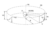
- the world coordinates are the cylindrical coordinates C0 with the vertical axis as an axis, but other three-dimensional coordinates such as celestial coordinates centered on the user U may be adopted.
- the radius R and height H of the cylindrical coordinates C0 can be set arbitrarily.
- the radius R is set shorter than the distance from the user U to the objects A1 to A4, but may be longer than the above distance.
- the height H is set to a size equal to or greater than the height (length in the vertical direction) Hv of the user's U visual field V provided via the HMD 100.
- the objects B1 to B4 are images that display information related to the objects A1 to A4 existing in the world coordinate system, and may be images including characters, patterns, etc., or animation images. Good.
- the object may be a two-dimensional image or a three-dimensional image.
- the shape of the object may be a rectangle, a circle, or other geometric shape, and can be set as appropriate depending on the type of the object.
- the coordinate positions of the objects B1 to B4 on the cylindrical coordinates C0 are associated with, for example, the intersecting positions of the user's eye line L watching the objects A1 to A4 and the cylindrical coordinates C0.
- the center position of each of the objects B1 to B4 is made coincident with the intersection position.
- the present invention is not limited to this, and a part of the periphery of the object (for example, part of the four corners) may coincide with the intersection position.
- the coordinate positions of the objects B1 to B4 may be associated with any position away from the intersection position.
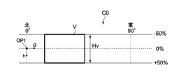
- the cylindrical coordinate C0 is a height in the height direction that represents a vertical coordinate axis ( ⁇ ) that represents an angle around the vertical axis with the north direction being 0 °, and a horizontal line of sight Lh of the user U.
- the coordinate axis ( ⁇ ) has a positive direction around the east, and the coordinate axis (h) has a depression angle as a positive direction and an elevation angle as a negative direction.
- the HMD 100 has a detection unit for detecting the viewpoint direction of the user U. Based on the output of the detection unit, the HMD 100 corresponds to which region on the cylindrical coordinate C0 the user's visual field V corresponds to. Judge whether to do. The HMD 100 displays (draws) the object B1 in the corresponding area when any object (for example, the object B1) exists in the corresponding area of the xy coordinate system forming the visual field V.
- the HMD 100 provides information related to the target A1 to the user U by displaying the object B1 in the field of view V so as to overlap the target A1 in the real space. Further, the HMD 100 can provide the user U with objects (B1 to B4) related to the predetermined objects A1 to A4 according to the orientation or direction of the viewpoint of the user U.
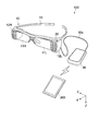
- FIG. 2 is an overall view showing the HMD 100
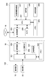
- FIG. 3 is a block diagram showing its configuration.
- the HMD 100 includes a display unit 10, a detection unit 20 that detects the attitude of the display unit 10, and a control unit 30 that controls driving of the display unit 10.
- the HMD 100 is configured as a see-through HMD that can provide a user with a visual field V in real space.
- the display unit 10 is configured to be attachable to the user U's head.
- the display unit 10 includes first and second display surfaces 11R and 11L, first and second image generation units 12R and 12L, and a support body 13.
- 1st and 2nd display surface 11R, 11L is comprised with the optical element which has transparency which can provide real space (external field visual field) to the right eye and left eye of the user U, respectively.
- the first and second image generation units 12R and 12L are configured to be able to generate images to be presented to the user U via the first and second display surfaces 11R and 11L, respectively.
- the support 13 supports the display surfaces 11R and 11L and the image generation units 12R and 12L, and the user's head so that the first and second display surfaces 11L and 11R face the right eye and the left eye of the user U, respectively. It has an appropriate shape that can be attached to the part.
- the display unit 10 configured as described above is configured to provide the user U with a field of view V in which a predetermined image (or virtual image) is superimposed on the real space via the display surfaces 11R and 11L. Is done.
- the detection unit 20 is configured to be able to detect a change in orientation or posture around at least one axis of the display unit 10.
- the detection unit 20 is configured to detect a change in orientation or posture of the display unit 10 around the X, Y, and Z axes.
- the orientation of the display unit 10 typically means the front direction of the display unit.
- the orientation of the display unit 10 is defined as the face direction of the user U.
- the detection unit 20 can be configured by a motion sensor such as an angular velocity sensor or an acceleration sensor, or a combination thereof.
- the detection unit 20 may be configured by a sensor unit in which each of the angular velocity sensor and the acceleration sensor is arranged in three axis directions, or the sensor to be used may be different depending on each axis.
- an integrated value of the output of the angular velocity sensor can be used as the posture change of the display unit 10, the direction of the change, the amount of the change, and the like.
- a geomagnetic sensor may be employed for detecting the orientation of the display unit 10 around the vertical axis (Z axis).
- the geomagnetic sensor and the motion sensor may be combined. Thereby, it is possible to detect a change in orientation or posture with high accuracy.
- the detection unit 20 is arranged at an appropriate position on the display unit 10.
- the position of the detection unit 20 is not particularly limited.
- the detection unit 20 is disposed on one of the image generation units 12R and 12L or a part of the support 13.
- the control unit 30 (first control unit) generates a control signal that controls driving of the display unit 10 (image generation units 12R and 12L) based on the output of the detection unit 20.
- the control unit 30 is electrically connected to the display unit 10 via a connection cable 30a.
- the present invention is not limited to this, and the control unit 30 may be connected to the display unit 10 through a wireless communication line.
- control unit 30 includes a CPU 301, a memory 302 (storage unit), a transmission / reception unit 303, an internal power supply 304, and an input operation unit 305.
- the CPU 301 controls the operation of the entire HMD 100.
- the memory 302 includes a ROM (Read Only Memory), a RAM (Random Access Memory), and the like, a program for executing control of the HMD 100 by the CPU 301, various parameters, an image (object) to be displayed on the display unit 10, and the like. Store the necessary data.
- the transmission / reception unit 303 constitutes an interface for communication with the portable information terminal 200 described later.
- the internal power supply 304 supplies power necessary for driving the HMD 100.
- the input operation unit 305 is for controlling an image displayed on the display unit 10 by a user operation.
- the input operation unit 305 may be configured with a mechanical switch or a touch sensor.
- the input operation unit 305 may be provided in the display unit 10.
- the HMD 100 may further include a sound output unit such as a speaker, a camera, and the like.
- the audio output unit and the camera are typically provided in the display unit 10.
- the control unit 30 may be provided with a display device that displays an input operation screen or the like of the display unit 10.
- the input operation unit 305 may be configured by a touch panel provided in the display device.
- the portable information terminal 200 (second control unit) is configured to be able to communicate with the control unit 30 via a wireless communication line.
- the portable information terminal 200 has a function of acquiring an image to be displayed on the display unit 10 and a function of transmitting the acquired image to the control unit 30.
- the portable information terminal 200 is organically combined with the HMD 100 to construct an HMD system.
- the portable information terminal 200 is carried by a user U who wears the display unit 10 and includes an information processing device such as a personal computer (PC: Personal Computer), a smartphone, a mobile phone, a tablet PC, or a PDA (Personal Digital Assistant).
- an information processing device such as a personal computer (PC: Personal Computer), a smartphone, a mobile phone, a tablet PC, or a PDA (Personal Digital Assistant).
- a terminal device dedicated to the HMD 100 may be used.
- the portable information terminal 200 includes a CPU 201, a memory 202, a transmission / reception unit 203, an internal power supply 204, a display unit 205, a camera 206, and a position information acquisition unit 207.
- the CPU 201 controls the operation of the mobile information terminal 200 as a whole.
- the memory 202 includes a ROM, a RAM, and the like, and stores programs and various parameters for executing control of the portable information terminal 200 by the CPU 201, images (objects) transmitted to the control unit 30, and other necessary data.
- the internal power supply 204 supplies power necessary for driving the portable information terminal 200.
- the transmission / reception unit 203 is connected to the server N, the control unit 30, other nearby portable information terminals, etc. using a wireless LAN (IEEE802.11, etc.) such as WiFi (Wireless Fidelity) or a 3G or 4G network for mobile communication. connect.
- the portable information terminal 200 downloads an image (object) to be transmitted to the control unit 30 and an application for displaying the image from the server N via the transmission / reception unit 203 and stores them in the memory 202.
- the server N is typically configured by a computer including a CPU, a memory, and the like, and transmits predetermined information to the portable information terminal 200 in response to a request from the user U or automatically regardless of the intention of the user U. .
- the display unit 205 is composed of, for example, an LCD or an OLED, and displays various menus, application GUIs, and the like. Typically, the display unit 205 is integrated with a touch panel and can accept a user's touch operation.
- the portable information terminal 200 is configured to be able to input a predetermined operation signal to the control unit 30 by a touch operation on the display unit 205.
- the location information acquisition unit 207 typically includes a GPS (Global Positioning System) receiver.
- the portable information terminal 200 is configured to be able to measure the current position of the user U (display unit 10) using the position information acquisition unit 207 and acquire a necessary image (object) from the server N. That is, the server N acquires information related to the current position of the user, and transmits image data, application software, and the like corresponding to the position information to the portable information terminal 200.
- FIG. 4 is a functional block diagram of the CPU 301.
- the CPU 301 includes a coordinate setting unit 311, an image management unit 312, a coordinate determination unit 313, and a display control unit 314.
- the CPU 301 executes processing in the coordinate setting unit 311, the image management unit 312, the coordinate determination unit 313, and the display control unit 314 according to the program stored in the memory 302.
- the coordinate setting unit 311 is configured to execute processing for setting three-dimensional coordinates surrounding the user U (display unit 10).
- cylindrical coordinates C0 (see FIG. 1) centered on the vertical axis Az are used as the three-dimensional coordinates.
- the coordinate setting unit 311 sets the radius R and the height H of the cylindrical coordinates C0.
- the coordinate setting unit 311 typically sets the radius R and the height H of the cylindrical coordinates C0 according to the number and type of objects to be presented to the user U.
- the radius R of the cylindrical coordinates C0 may be a fixed value, but may be a variable value that can be arbitrarily set according to the size (pixel size) of the image to be displayed.
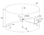
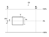
- the height H of the cylindrical coordinates C0 is set to, for example, 1 to 3 times the height Hv (see FIG. 1) of the vertical direction (vertical direction) of the visual field V provided to the user U by the display unit 10. Is done.
- the upper limit of the height H is not limited to 3 times Hv, but may be a size exceeding 3 times Hv.
- FIG. 5A shows a cylindrical coordinate C0 having the same height H1 as the height Hv of the visual field V.
- FIG. 5B shows a cylindrical coordinate C0 having a height H2 that is three times the height Hv of the field of view V.
- FIGS. 6A and 6B are schematic diagrams showing the cylindrical coordinates C0 in an expanded manner.
- the cylindrical coordinate C0 represents the angle in the vertical direction with reference to the circumferential coordinate axis ( ⁇ ) representing the angle around the vertical axis with the north direction being 0 ° and the horizontal line of sight Lh of the user U.
- a coordinate axis (h) in the height direction a coordinate axis ( ⁇ ) has a positive direction around the east, and the coordinate axis (h) has a depression angle as a positive direction and an elevation angle as a negative direction.
- the coordinate setting unit 311 has a function as a region limiting unit capable of limiting the display region along the uniaxial direction of the visual field V in the three-dimensional coordinates surrounding the display unit 10.
- the coordinate setting unit 311 limits the visual field region (Hv) in the height direction of the visual field V at the cylindrical coordinates C0 surrounding the display unit 10.
- the coordinate setting unit 311 determines that the height (H) of the cylindrical coordinates is an area in the height direction of the visual field V when the specified value of the height (H) is larger than the height Hv of the visual field V.
- the coordinate setting unit 311 limits the height of the cylindrical coordinates from H2 (FIG. 5B) to H1 (FIG. 5A), for example, according to the operation by the user U.
- the image management unit 312 has a function of managing the images stored in the memory 302. For example, the image management unit 312 stores one or a plurality of images displayed via the display unit 10 in the memory 302 and stores them in the memory 302. It is configured to execute a process of selectively deleting the processed image. An image stored in the memory 302 is transmitted from the portable information terminal 200. The image management unit 312 also requests the portable information terminal 200 to transmit an image via the transmission / reception unit 303.
- the memory 302 is configured to store one or a plurality of images (objects) to be displayed in the visual field V in association with the cylindrical coordinates C0. That is, the memory 302 stores the individual objects B1 to B4 on the cylindrical coordinates C0 shown in FIG. 1 together with the coordinate positions on the cylindrical coordinates C0.
- each of the objects B1 to B4 to be displayed corresponding to the azimuth or orientation of the visual field V occupies a coordinate area on a specific cylindrical coordinate C0, and specific coordinates in that area It is stored in the memory 302 together with the position P ( ⁇ , h).
- the coordinate positions of the objects B1 to B4 may be set to any position within the display area of each object B1 to B4, or may be set to one specific point (for example, the center position) for each object. Two or more points (for example, two diagonal points or four corner points) may be set.
- the coordinate positions of the objects B1 to B4 are associated with the intersection position of the user's line of sight L that looks at the objects A1 to A4 and the cylindrical coordinates C0, the user U has the object B1.
- To B4 are visually recognized at positions overlapping the objects A1 to A4.
- the coordinate positions of the objects B1 to B4 may be associated with an arbitrary position away from the intersection position.
- the objects B1 to B4 can be displayed or drawn at desired positions with respect to the objects A1 to A4.
- the coordinate determination unit 313 is configured to execute a process of determining which region on the cylindrical coordinates C0 corresponds to the field of view V of the user U based on the output of the detection unit 20. That is, the visual field V moves on the cylindrical coordinates C0 due to a change in the posture of the user U (display unit 10), and the movement direction and movement amount are calculated based on the output of the detection unit 20.
- the coordinate determination unit 313 calculates the movement direction and movement amount of the display unit 10 based on the output of the detection unit 20, and determines to which region on the cylindrical coordinates C0 the visual field V belongs.
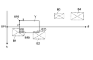
- FIG. 8 is a development view of the cylindrical coordinates C0 conceptually showing the relationship between the visual field V on the cylindrical coordinates C0 and the objects B1 to B4.
- the field of view V is substantially rectangular and has xy coordinates (local coordinates) with the upper left corner as the origin OP2.
- the x axis is an axis extending in the horizontal direction from the origin OP2, and the y axis is an axis extending in the vertical direction from the origin OP2.
- the coordinate determination unit 313 is configured to execute processing for determining whether any of the objects B1 to B4 exists in the corresponding region of the visual field V.
- the display control unit 314 executes processing for displaying (drawing) an object on the cylindrical coordinates C0 corresponding to the orientation of the display unit 10 in the visual field V based on the output of the detection unit 20 (that is, the determination result of the coordinate determination unit 313). Configured to do. For example, as shown in FIG. 8, when the current orientation of the visual field V overlaps the display areas of the objects B1 and B2 on the cylindrical coordinates C0, images corresponding to the overlapping areas B10 and B20 are displayed in the visual field V. (Local rendering: Local) Rendering).
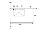
- 9A and 9B are diagrams for explaining a conversion method from the cylindrical coordinates C0 (world coordinates) to the visual field V (local coordinates).
- the coordinates of the reference point of the visual field V on the cylindrical coordinates C0 are ( ⁇ v, hv), and the coordinates of the reference point of the object B located in the region of the visual field V are ( ⁇ 0, h0).
- the reference point of the field of view V and the object B may be set to any point, and in this example, the reference point is set at the upper left corner of the field of view V and the object B which are rectangular.
- ⁇ v [°] is the width angle of the visual field V on the world coordinates, and its value is determined by the design or specification of the display unit 10.
- the display control unit 314 determines the display position of the object B in the visual field V by converting the cylindrical coordinate system ( ⁇ , h) to the local coordinate system (x, y). As shown in FIG. 9B, if the height and width of the field of view V in the local coordinate system are Hv and Wv, respectively, and the coordinates of the reference point of the object B in the local coordinate system (x, y) are (x0, y0), conversion is performed.
- the display control unit 314 typically changes the display position of the object B within the field of view V following the change in the orientation or orientation of the display unit 10. This control is continued as long as at least part of the object B exists in the visual field V.
- the display area tends to be narrowed with the miniaturization of the HMD.
- the see-through type head mounted display for example, there is a case where it is desired to restrict the information display area while securing the see-through area.
- the HMD 100 of the present embodiment has an object display fixing function as described below.
- ⁇ Object display fixing function> (1) Introduction of Non Strict attribute
- the display control unit 314 moves an object within the field of view V according to the change of the azimuth or posture when the azimuth or posture of the display unit 10 changes by a predetermined angle or more.
- a process for fixing the display position of the object in the visual field V is configured to be executable.
- a non-strict attribute may be introduced into the object. That is, when the object B is not fixed to one place in the world coordinate system (cylindrical coordinates C0) but within a certain angle range in which the user U is looking, the local coordinate system (x, y) of the display unit 10 is displayed. ) May be fixedly displayed.
- the visibility of the object can be improved by restricting the movement of the object due to an inadvertent posture change around the vertical axis or the horizontal axis of the user U.
- the predetermined angle may be an angle around the vertical axis (Z axis), an angle around the horizontal axis (X axis and / or Y axis), or both of them.
- the value of the predetermined angle can be set as appropriate, for example, ⁇ 15 °.
- the predetermined angle may be the same around the vertical axis (first predetermined angle) and the horizontal axis (second predetermined angle), or may be different from each other.
- the display control unit 314 is configured to be able to execute a process of moving the object B to a predetermined position in the field of view V when the output change of the detection unit 20 is not more than a predetermined value over a predetermined time.
- the output of the detection unit 20 when the output of the detection unit 20 does not change over a predetermined time, it is highly likely that the user is referring to the object displayed in the field of view V. Therefore, the object is moved to a predetermined position in the field of view V. You may make it improve the visibility of an object.
- the predetermined time is not particularly limited, and is set to about 5 seconds, for example.
- the predetermined position is not particularly limited, and is, for example, a position that is biased to the center or corner of the field of view V, or to the top, bottom, left or right. Furthermore, the moved object may be exaggerated such as enlarged.
- the function sets the object B to the predetermined of the local coordinate system (x, y) of the field of view V. You may make it carry out fixed display to a position. In this case, when the output of the detection unit 20 exceeds a predetermined value, the fixed display function of the object is canceled.
- the output value of the detection unit 20 at this time may be an output change amount corresponding to an attitude change of a predetermined angle or more around the predetermined axis of the display unit 10 described above, or other output change amount. May be.
- the display control unit 314 is configured to be able to execute a process of moving an object to a predetermined position in the visual field V when detecting an input of a predetermined signal generated by an operation of the user U. . Even in such a configuration, the visibility of the object can be improved as described above, and the display of the image can be controlled in accordance with the user's intention.
- the object is fixed to the local coordinate system (x, y) of the visual field V by performing a predetermined input operation on the input operation unit 305 or the portable information terminal 200 with the object aligned with the center of the visual field V. Is done. Then, by operating the input operation unit 305 again, the object returns to the world coordinate system, and the fixed display function of the object is released.
- the display control unit 31 when an object is displayed at a predetermined position of the visual field V, when the output change of the detection unit 20 is equal to or higher than a predetermined frequency, It is configured to be able to execute processing for invalidating frequency components above the frequency.
- the object in the field of view V moves following the change in the orientation or orientation of the display unit 10
- the user U may also follow a small facial shake, which may deteriorate the visibility of the object.
- the object is not allowed to follow the posture change of the display unit 10 for high-frequency components that are greater than or equal to a predetermined value, and the display position of the object for the low-frequency components that are less than a predetermined value is System).
- the predetermined frequency for example, a frequency corresponding to a user's face shake is set. Thereby, the visibility of the image can be ensured without being affected by the fine face shake of the user.
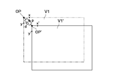
- V1 represents a local coordinate system at a certain point in time
- V2 represents an image stabilization coordinate system corresponding to V1.
- OP and OP ' indicate the origins of V1 and V2.
- PD control is a type of feedback control, and generally refers to control that converges to a set value by combining proportional control (Proportional Control) and differential control (Differential Control).
- Proportional Control Proportional Control
- Differential Control differential control
- a point in the local coordinate system V1 at a certain time t is defined as (x (t), y (t)), and a corresponding point in the image stabilization coordinate system V2 is defined as (x '(t), y' (t)).
- the point of the local coordinate system V1 before the sampling period ( ⁇ t) is set to (x (t ⁇ t), y (t ⁇ t)), and the corresponding point of the image stabilization coordinate system V2 is set to (x ′ (t ⁇ t). ), Y ′ (t ⁇ t)).
- ⁇ p (t), ⁇ q (t) Px ⁇ ⁇ x (t) + Dx ⁇ ⁇ vx (t) (7)
- ⁇ q (t) Py ⁇ ⁇ y (t) + Dy ⁇ ⁇ vy (t) (8) It is expressed.
- Px and Py are differential gain constants for x and y
- Dx and Dy are velocity gain constants for x and y.
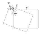
- the image stabilization coordinate system V1 'does not follow the rotation component (FIG. 10B). That is, the tilt of the object is restricted even when the face is tilted about the axis in the front-rear direction of the user.
- the object display fixing functions (1) to (4) described above may be applied individually, or may be applied by appropriately combining the functions. For example, a combination of any one of the above (1) to (3) and the above (4) is applicable.
- the present embodiment has a world coordinate system area restriction function for the purpose of improving the searchability of objects.
- the coordinate setting unit 311 can limit the region (H) along the Z-axis direction in the cylindrical coordinates C0 surrounding the display unit 10 according to the region (Hv) in the height direction of the visual field V. It has a function as an area limiter (see FIG. 5A). By limiting the height H of the cylindrical coordinates C0, it is possible to improve the searchability and visibility of images in the user's horizontal visual field.
- the amount of restriction in the height direction of the cylindrical coordinates C0 is not particularly limited, and in this embodiment, the height of the cylindrical coordinates C0 is limited to the same height (H1) as the height Hv of the visual field V.
- the display control unit 314 includes at least one of the cylindrical coordinate systems ( ⁇ , h) so that the objects B1 to B4 are positioned within the area-restricted cylindrical coordinates C0. It is configured such that the objects B1 to B4 can be displayed in the field of view V by changing the h coordinate.
- FIG. 11A and 11B are schematic diagrams showing the relative positional relationship between the objects B1 to B4 associated with the cylindrical coordinates C1 whose area is limited to the height H1 and the visual field V.
- FIG. Since the user U can visually recognize the objects B1 to B4 associated with all the directions only by changing the posture around the Z axis (vertical axis), the searchability of the objects B1 to B4 is dramatically improved. Will do.
- all the objects B1 to B4 are arranged in the cylindrical coordinates C1, but the present invention is not limited to this, and at least one object may be arranged in the cylindrical coordinates C1 as necessary. Further, the heights of the objects B1 to B4 arranged at the cylindrical coordinates C1 are not particularly limited and can be arbitrarily set.
- the entire objects B1 to B4 are arranged in the cylindrical coordinates C1, but at least a part of the objects B1 to B4 may be displayed in the field of view V.
- the image existing in a certain direction can be easily recognized.
- the height H1 of the cylindrical coordinates C1 may be configured to be changeable to a height higher than this by an input operation by the user U to the input operation unit 305 or the like. Thereby, the whole object can be visually recognized.
- Whether to enable or disable the area restriction function described above may be configured to be selectable by setting by the user U.
- the HMD 100 according to the present embodiment is set in a normal mode in which the area restriction function using the world coordinate system as the cylindrical coordinates C1 is enabled, and the area restriction function is changed by the user's spontaneous setting change (for example, high Change of the height H) or switching to an invalid state.
- control unit 30 detects the input of the predetermined signal generated by the operation of the user U, the control unit 30 limits the height direction area in the cylindrical coordinates according to the height direction area (Hv) of the visual field V.
- the processing for aligning all objects displayed in the field of view V to the same height in the field of view V may be executed.
- the area restriction function is in an invalid state or when the world coordinate system is set to a cylindrical coordinate other than the cylindrical coordinate C1
- the world coordinate system is changed by an input operation to the input operation unit 305 or the like by the user U. It is forcibly switched to the cylindrical coordinate C1.
- the objects B1 to B4 are arranged in the cylindrical coordinates C1 at positions where all the objects B1 to B4 are displayed at the same height in the field of view V as shown in FIG. 11B. Thereby, the further improvement of the visibility of the image displayed on the visual field can be aimed at.
- the portable information terminal 200 is used to transmit object data to the control unit 30.
- the portable information terminal 200 can acquire a position information acquisition unit 207 for measuring the position of the user U (display unit 10) and a plurality of objects (B1 to B4) to be stored in the memory 302 of the control unit 30 from the server N or the like.
- An image acquisition unit including a simple transmission / reception unit 203 and the like.
- control unit 30 requests the portable information terminal 200 to transmit one or more object data selected from the plurality of object data, and the portable information terminal 200 requests the control unit 30 to Sent object data.
- the control unit 30 (in this example, the image management unit 312) is configured as follows in order to avoid the communication speed and latency problems.
- control unit 30 is configured to acquire a plurality of necessary object data from the portable information terminal 200 in advance. Thereby, the drawing timing of the object in the visual field V can be controlled on the control unit 30 side, and a necessary object can be provided to the user U at an appropriate timing regardless of the communication environment.
- control unit 30 is configured to request the portable information terminal 200 to preferentially transmit an object associated with a coordinate position closer to the display area of the visual field V on the cylindrical coordinate C0. By preferentially acquiring object data that is likely to be presented to the visual field V in this way, it is possible to prevent a delay in displaying an object in the visual field V.
- the image management unit 312 is configured to first set one or a plurality of frames corresponding to the arrangement positions of the objects on the world coordinates, and then execute a process of arranging an object with a high priority in the frames. Is done. “Place a frame or object on world coordinates” means that a frame or object is associated on world coordinates.
- FIG. 12A, FIG. 12B, and FIG. 13 show a procedure for arranging the objects B3 and B4 on the cylindrical coordinates C1 whose area is limited to the height H1.
- the following procedure is also applicable to a world coordinate system composed of cylindrical coordinates C0 or other three-dimensional coordinates that are not limited in area.
- each of the image data (object data) of the object and the frame data that determines the coordinate position of the object are transmitted from the portable information terminal 200 to the control unit 30. Since the frame data has a smaller amount of data than the object data, it does not take time to obtain it compared to the object data. For this reason, communication for acquiring frame data is performed first, and communication for acquiring object data is performed later in order of priority.
- the portable information terminal 200 confirms whether or not it is necessary to transmit the frame F3 for arranging the object B3 to the control unit 30 (step 101). In contrast, the control unit 30 transmits the frame F3 to the portable information terminal 200. Request transmission (step 102). The control unit 30 stores the received frame F3 in the memory 302, thereby arranging the frame F3 at a corresponding position on the cylindrical coordinate C1.
- the portable information terminal 200 confirms whether or not it is necessary to transmit the frame F4 for arranging the object B4 to the control unit 30 (step 103), and the control unit 30 sends a frame F4 to the portable information terminal 200. Is requested (step 104).
- the control unit 30 stores the received frame F4 in the memory 302, thereby arranging the frame F4 at a corresponding position on the cylindrical coordinate C1.
- the portable information terminal 200 notifies the control unit 30 of permission to transmit object data (step 105).
- the control unit 30 proceeds to the data acquisition phase with the object data transmission permission notification as a trigger. Specifically, for example, based on the output of the detection unit 20, the control unit 30 determines a frame (in this example, the frame F4) that is closest to the orientation of the current visual field V (display unit 10), and objects belonging to the frame The transmission of the image data of (object B4 in this example) is requested (step 106). In response to this request, the portable information terminal 200 transmits the image data of the object B4 to the control unit 30 (step 107). The control unit 30 stores the received image data of the object B4 in the memory 302, thereby arranging the object B4 in the frame F4 on the cylindrical coordinates C1.
- the control unit 30 determines a frame (frame F3 in this example) closest to the direction of the field of view V next to the frame F4, and requests transmission of image data of an object (object B3 in this example) belonging to the frame. (Step 108).
- the portable information terminal 200 transmits the image data of the object B3 to the control unit 30 (step 109).
- the control unit 30 stores the received image data of the object B3 in the memory 302, thereby arranging the object B3 in the frame F3 on the cylindrical coordinates C1.
- control unit 30 can determine the object acquisition priority based on the current visual field V by registering the object frame data in advance on the cylindrical coordinates C1. Based on this, the image data is sequentially acquired from an object having a high priority (closest to the visual field V).
- the control unit 30 is configured to request the portable information terminal 200 to collectively transmit at least a part of all the images constituting the animation image. In this way, even if the object is an animation image, it can be dynamically handled by caching the required number of images (for example, images up to 1 second later) in consideration of the frame rate. it can.
- control unit 30 periodically evaluates the distance between the coordinate position of each object stored in the memory 302 and the display area of the visual field V, and stores the object at the coordinate position farthest from the display area of the visual field V. It may be configured to delete from 302. Specifically, the priorities of all the objects are evaluated based on the relative positional relationship between all the objects on the cylindrical coordinates C1 and the current azimuth of the visual field V, and the object data with a low priority is deleted. Thereby, a storage area for object data close to the visual field V can be secured.
- the priority evaluation method is not particularly limited, and can be evaluated based on, for example, the number of pixels between the center position of the visual field V and the center position of the object in the cylindrical coordinates C1.
- the evaluation value may be multiplied by a coefficient based on the reproduction time.
- FIG. 14 is a flowchart for explaining an outline of the operation of the HMD system according to the present embodiment.
- the current position of the user U is measured using the position information acquisition unit 207 of the portable information terminal 200 (step 201).
- the position information of the display unit 10 is transmitted to the server N.
- the portable information terminal 200 acquires object data related to a predetermined object existing in the real space around the user U from the server N (step 202).
- the control unit 30 sets the height (H) and radius (R) of the cylindrical coordinates C0 as the world coordinate system according to the type of object data and the like (step 203).
- the coordinate setting unit 311 sets the world coordinate system to, for example, the cylindrical coordinate C1 illustrated in FIG. 12A. Set.
- control unit 30 detects the azimuth of the visual field V based on the output of the detection unit 20 (step 204), acquires object data from the portable information terminal 200, and stores it in the memory 302 (step 205).
- FIG. 15 is a flowchart showing an example of a procedure for receiving object data by the control unit 30.
- the control unit 30 After receiving the object data transmission permission confirmation from the portable information terminal 200 (step 301), the control unit 30 determines whether or not the frame registration of all objects is completed (step 302). This is because if the frame registration of all objects is not completed, the coordinate position of the object cannot be determined, and the priority of the object cannot be evaluated. If the frame registration is incomplete, the process is terminated, and the above-described incomplete frame registration process is executed.
- step 303 when the frame registration of all the objects is completed, the presence / absence of an object not received and the capacity of the memory 302 are confirmed (step 303). If there is an unregistered object and the memory capacity is sufficient, the unregistered object is received and stored in the memory 302 (step 304).
- control unit 30 periodically evaluates the priority of the object in the memory 302, and deletes a low evaluation value as necessary.
- the control unit 30 displays (draws) the object at the corresponding position of the visual field V via the display unit 10 (step 206). ).
- any of the above-described object display fixing functions may be applied.
- FIG. 16 is a flowchart illustrating an example of a procedure for drawing an object on the field of view V by the control unit 30.
- the control unit 30 calculates the current orientation of the visual field V based on the output of the detection unit 20 (step 401).
- the orientation of the visual field V is converted into the world coordinate system ( ⁇ , h), and it is monitored which position on the cylindrical coordinates C0 corresponds to.
- control unit 30 determines whether there is an object that has not been scanned among all the objects stored in the memory 302 (step 402).
- the scan is performed on all objects stored in the memory 302 every time the screen is updated.
- step 403 If there is an unscanned object, it is determined whether the object is a world coordinate system object (step 403), and if “No”, the object is drawn in the field of view V (step 404).
- step 403 determines whether any of the object display fixing functions (for example, the first grab function) is applied to the object (step 405). If the function is applied, the object is fixedly displayed in the field of view V when a predetermined condition is satisfied (step 406). On the other hand, when any display fixing function is not applied, the object is drawn in the visual field V when the visual field V enters the object position (step 407).
- the object display fixing functions for example, the first grab function
- the head-mounted display is configured to be worn on the user's head and can provide the user with a real space field of view, a detection unit that detects the orientation of the display unit, and the detection unit
- a display control unit for displaying an image in the field of view based on the output.
- the display control unit moves the image within the field of view according to the change in the azimuth when the azimuth changes by a first predetermined angle or more.
- the display control unit fixes the display position of the image in the field of view when the change in orientation is less than the first predetermined angle.
- the display unit and the detection unit correspond to the display unit 10 and the detection unit 20 described in the first embodiment, respectively.
- the display control unit corresponds to the display control unit 314 having the object display fixing function ((1) introduction of non-strict attributes) described in the first embodiment.
- the head mounted display of this embodiment can be applied to any other coordinate system in which the world coordinates are not limited to cylindrical coordinates. Also in this embodiment, the same effect as that of the first embodiment can be obtained. That is, since the state in which the object is in the visual field can be easily maintained, the movement of the object due to the user's inadvertent posture change can be restricted, and the visibility of the object can be improved.
- At least one of an area restriction function and an image management function may be provided.
- the head-mounted display is configured to be worn on the user's head and can provide the user with a real space field of view, a detection unit that detects the orientation of the display unit, and the detection unit
- a display control unit for displaying an image in the field of view based on the output.
- the display control unit moves the image to a predetermined position in the field of view when an output change of the detection unit is not more than a predetermined value for a predetermined time.
- the display control unit detects an input of a predetermined signal generated by a user operation, the display control unit moves the image to a predetermined position in the visual field.
- the display unit and the detection unit correspond to the display unit 10 and the detection unit 20 described in the first embodiment, respectively.
- the display control unit corresponds to the display control unit 314 having the object display fixing function ((2) the first grab function or (3) the second grab function) described in the first embodiment.
- the head mounted display of this embodiment can be applied to any other coordinate system in which the world coordinates are not limited to cylindrical coordinates. Also in this embodiment, the same effect as that of the first embodiment can be obtained. That is, since the state in which the object is in the visual field can be easily maintained, the movement of the object due to the user's inadvertent posture change can be restricted, and the visibility of the object can be improved.
- At least one of an area restriction function and an image management function may be provided.
- the head-mounted display is configured to be worn on the user's head and can provide the user with a real space field of view, a detection unit that detects the orientation of the display unit, and the detection unit
- a display control unit that displays an image in the field of view based on the output is provided.
- the display control unit has a frequency component equal to or higher than the predetermined frequency in the output of the detection unit when the output change of the detection unit is equal to or higher than a predetermined frequency. Is invalid.
- the display unit and the detection unit correspond to the display unit 10 and the detection unit 20 described in the first embodiment, respectively.
- the display control unit corresponds to the display control unit 314 having the object display fixing function ((4) face correction function) described in the first embodiment.
- the head mounted display of this embodiment can be applied to any other coordinate system in which the world coordinates are not limited to cylindrical coordinates. Also in this embodiment, the same effect as the above-mentioned first embodiment can be obtained. That is, the visibility of the image can be ensured without being affected by the fine face shake of the user.
- At least one of an area restriction function and an image management function may be provided.
- HMD head-up display
- a see-through type (transmission type) HMD has been described.
- the present technology can also be applied to a non-transmission type HMD.
- a predetermined object according to the present technology may be displayed in an external field of view captured by a camera attached to the display unit.
- the HMD 100 is configured to display an object including information related to a predetermined object existing in the real space in the field of view V.
- the present invention is not limited to this, and the current position of the user U A destination guidance display or the like may be displayed in the field of view V based on the traveling direction.
- this technique can also take the following structures.
- a display unit configured to be worn on the user's head and capable of providing a real-world field of view to the user;
- a detection unit for detecting an orientation around at least one axis of the display unit;
- An area restriction unit capable of restricting a display area along the uniaxial direction of the field of view in three-dimensional coordinates surrounding the display unit, and stores an image to be displayed in the field of view in association with the three-dimensional coordinate
- a display control unit for displaying an image on the three-dimensional coordinate corresponding to the orientation in the field of view based on an output of the detection unit, and a first control unit.
- the detection unit detects an orientation around a vertical axis of the display unit
- the area restriction unit restricts a height direction area in cylindrical coordinates around a vertical axis according to a vertical area of the visual field.
- the region limiting unit limits a region in a height direction of the cylindrical coordinates to a height at which at least a part of an image stored in the storage unit is displayed in the visual field.
- the head mounted display according to any one of (1) to (3) above, The display control unit When the azimuth has changed by more than a first predetermined angle, the image is moved in the field of view according to the change in the azimuth, A head mounted display that fixes a display position of the image in the field of view when the change in orientation is less than the first predetermined angle.
- the detection unit further detects a change in posture around the horizontal axis of the display unit, The display control unit When the posture change is equal to or greater than a second predetermined angle, the image is moved in the field of view according to the posture change, A head-mounted display that fixes a display position of the image in the field of view when the posture change is less than the second predetermined angle.
- the head mounted display according to any one of (1) to (3) above, The display control unit moves the image to a predetermined position in the field of view when an output change of the detection unit is not more than a predetermined value for a predetermined time.
- the display control unit In the state where the image is displayed at a predetermined position in the visual field, the display control unit is configured to output a frequency component equal to or higher than the predetermined frequency in the output of the detection unit when an output change of the detection unit is equal to or higher than a predetermined frequency.
- Disable head mounted display (9) The head mounted display according to any one of (1) to (8) above, When the first control unit detects an input of a predetermined signal generated by a user operation, the first control unit limits a height direction region in the three-dimensional coordinates according to the uniaxial region of the visual field, A head mounted display that aligns all images displayed in the field of view at the same height in the field of view.
- the detection unit includes a geomagnetic sensor.
- a head-mounted display further comprising a second control unit having an image acquisition unit that acquires a plurality of images stored in the storage unit.
- the head mounted display according to (14) above The first control unit requests the second control unit to transmit one or more images selected from the plurality of images. Head mounted display. (16) The head mounted display according to (13) or (14) above, The first control unit requests the second control unit to preferentially transmit an image associated with a coordinate position closer to the display area of the visual field on the three-dimensional coordinate. . (17) The head mounted display according to (16) above, The image is an animated image; The first control unit requests the second control unit to collectively transmit at least a part of all the images constituting the animation image.
- the head mounted display according to (16) or (17) above The first control unit periodically evaluates the distance between the coordinate position of each of the images stored in the storage unit and the display area of the visual field, and sets the coordinate position farthest from the display area of the visual field. A head-mounted display that deletes an image from the storage unit. (19) The head mounted display according to any one of (14) to (18) above, The second control unit further includes a position information acquisition unit capable of acquiring position information of the display unit, The image acquisition unit acquires an image corresponding to the position information that can be transmitted to the first control unit.
- SYMBOLS 10 Display part 11R, 11L ... Display surface 12R, 12L ... Image generation part 20 ... Detection part 30 ...
- Control unit 100 Head mounted display (HMD)
- DESCRIPTION OF SYMBOLS 200 ... Portable information terminal 311 ... Coordinate setting part 312 ... Image management part 313 ... Coordinate determination part 314 ... Display control part A1-A4 ... Object B, B1-B4 ... Object C0, C1 ... Cylindrical coordinate (world coordinate) V ... Field of view U ... User
Priority Applications (5)
| Application Number | Priority Date | Filing Date | Title |
|---|---|---|---|
| EP13875857.8A EP2960896B1 (de) | 2013-02-22 | 2013-12-16 | Kopfmontierte anzeige und bildanzeigevorrichtung |
| JP2014544282A JP6287849B2 (ja) | 2013-02-22 | 2013-12-16 | ヘッドマウントディスプレイ、画像表示装置及び画像表示方法 |
| CN201380020175.2A CN104246864B (zh) | 2013-02-22 | 2013-12-16 | 头戴式显示器和图像显示装置 |
| EP22185568.7A EP4099136A1 (de) | 2013-02-22 | 2013-12-16 | Kopfmontierte anzeige und bildanzeigevorrichtung |
| US14/394,514 US9709806B2 (en) | 2013-02-22 | 2013-12-16 | Head-mounted display and image display apparatus |
Applications Claiming Priority (2)
| Application Number | Priority Date | Filing Date | Title |
|---|---|---|---|
| JP2013-033076 | 2013-02-22 | ||
| JP2013033076 | 2013-02-22 |
Publications (1)
| Publication Number | Publication Date |
|---|---|
| WO2014128810A1 true WO2014128810A1 (ja) | 2014-08-28 |
Family
ID=51390650
Family Applications (2)
| Application Number | Title | Priority Date | Filing Date |
|---|---|---|---|
| PCT/JP2013/007386 WO2014128810A1 (ja) | 2013-02-22 | 2013-12-16 | ヘッドマウントディスプレイ及び画像表示装置 |
| PCT/JP2014/000957 WO2014129204A1 (ja) | 2013-02-22 | 2014-02-24 | ヘッドマウントディスプレイ |
Family Applications After (1)
| Application Number | Title | Priority Date | Filing Date |
|---|---|---|---|
| PCT/JP2014/000957 WO2014129204A1 (ja) | 2013-02-22 | 2014-02-24 | ヘッドマウントディスプレイ |
Country Status (5)
| Country | Link |
|---|---|
| US (7) | US9709806B2 (de) |
| EP (2) | EP4099136A1 (de) |
| JP (5) | JP6287849B2 (de) |
| CN (2) | CN104246864B (de) |
| WO (2) | WO2014128810A1 (de) |
Cited By (10)
| Publication number | Priority date | Publication date | Assignee | Title |
|---|---|---|---|---|
| JP2016181302A (ja) * | 2016-07-13 | 2016-10-13 | 株式会社コロプラ | 没入型仮想空間でオブジェクト操作を制御するためのコンピュータ・プログラムおよびコンピュータ・システム |
| JP2017055173A (ja) * | 2015-09-07 | 2017-03-16 | 株式会社ソニー・インタラクティブエンタテインメント | 情報処理装置および画像生成方法 |
| KR20170095823A (ko) * | 2014-12-18 | 2017-08-23 | 인텔 코포레이션 | 헤드 장착 디스플레이 업데이트 버퍼 |
| US20170278486A1 (en) * | 2014-08-27 | 2017-09-28 | Sony Corporation | Display control apparatus, display control method, and program |
| JP2018524673A (ja) * | 2015-06-01 | 2018-08-30 | トムソン ライセンシングThomson Licensing | 仮想現実の反応性アニメーション |
| JP2018165985A (ja) * | 2018-05-24 | 2018-10-25 | 株式会社ソニー・インタラクティブエンタテインメント | 情報処理装置および画像生成方法 |
| WO2019031397A1 (ja) * | 2017-08-07 | 2019-02-14 | ナーブ株式会社 | 画像表示装置、画像表示方法及び画像表示プログラム |
| JP2019201307A (ja) * | 2018-05-16 | 2019-11-21 | キヤノン株式会社 | 電子機器、電子機器の制御方法、プログラム、及び、記憶媒体 |
| WO2020059028A1 (ja) * | 2018-09-18 | 2020-03-26 | マクセル株式会社 | ヘッドマウントディスプレイ及びオブジェクトの表示方法 |
| US10740971B2 (en) | 2015-01-20 | 2020-08-11 | Microsoft Technology Licensing, Llc | Augmented reality field of view object follower |
Families Citing this family (61)
| Publication number | Priority date | Publication date | Assignee | Title |
|---|---|---|---|---|
| CN104246864B (zh) * | 2013-02-22 | 2016-06-29 | 索尼公司 | 头戴式显示器和图像显示装置 |
| JP6260613B2 (ja) * | 2013-02-22 | 2018-01-17 | ソニー株式会社 | ヘッドマウントディスプレイシステム、ヘッドマウントディスプレイ、ヘッドマウントディスプレイ制御プログラム、画像表示方法及び画像表示装置 |
| US9508195B2 (en) * | 2014-09-03 | 2016-11-29 | Microsoft Technology Licensing, Llc | Management of content in a 3D holographic environment |
| WO2016051429A1 (ja) * | 2014-09-30 | 2016-04-07 | 株式会社ブリリアントサービス | 入出力装置、入出力プログラム、および入出力方法 |
| WO2016051430A1 (ja) * | 2014-09-30 | 2016-04-07 | 株式会社ブリリアントサービス | 入出力装置、入出力プログラム、および入出力方法 |
| JP6399692B2 (ja) * | 2014-10-17 | 2018-10-03 | 国立大学法人電気通信大学 | ヘッドマウントディスプレイ、画像表示方法及びプログラム |
| JP2016096513A (ja) * | 2014-11-17 | 2016-05-26 | 株式会社ゼンリンデータコム | 情報処理システム、情報処理方法及びプログラム |
| JP6550734B2 (ja) * | 2014-12-02 | 2019-07-31 | セイコーエプソン株式会社 | 頭部装着型表示装置、頭部装着型表示装置の制御方法、および、コンピュータープログラム |
| JP2016110319A (ja) * | 2014-12-04 | 2016-06-20 | ソニー株式会社 | 表示制御装置、表示制御方法およびプログラム |
| CN104615241B (zh) * | 2015-01-04 | 2017-08-25 | 谭希韬 | 基于头转动的穿戴式眼镜控制方法和系统 |
| US10827950B2 (en) * | 2015-03-04 | 2020-11-10 | California Institute Of Technology | Position sensing and guiding system |
| JP6481456B2 (ja) * | 2015-03-26 | 2019-03-13 | 富士通株式会社 | 表示制御方法、表示制御プログラム、及び情報処理装置 |
| JP6439935B2 (ja) * | 2015-05-07 | 2018-12-19 | パナソニックIpマネジメント株式会社 | 表示制御方法、ヘッドマウントディスプレイ、およびプログラム |
| JP2016218268A (ja) * | 2015-05-21 | 2016-12-22 | セイコーエプソン株式会社 | 可搬型表示装置、表示システム、表示方法 |
| JP6344311B2 (ja) * | 2015-05-26 | 2018-06-20 | ソニー株式会社 | 表示装置、情報処理システム及び制御方法 |
| US9520002B1 (en) * | 2015-06-24 | 2016-12-13 | Microsoft Technology Licensing, Llc | Virtual place-located anchor |
| CN106303404A (zh) * | 2015-06-29 | 2017-01-04 | 北京智谷睿拓技术服务有限公司 | 可视化内容传输控制方法、发送方法、及其装置 |
| JP6611501B2 (ja) * | 2015-07-17 | 2019-11-27 | キヤノン株式会社 | 情報処理装置、仮想オブジェクトの操作方法、コンピュータプログラム、及び記憶媒体 |
| US20180204387A1 (en) * | 2015-07-28 | 2018-07-19 | Hitachi, Ltd. | Image generation device, image generation system, and image generation method |
| CN105183148A (zh) * | 2015-08-03 | 2015-12-23 | 众景视界(北京)科技有限公司 | 用于头戴式智能设备的平移检测方法及平移检测装置 |
| JP5913709B1 (ja) * | 2015-09-29 | 2016-04-27 | 株式会社コロプラ | 画像生成装置、画像生成方法、及び画像生成プログラム |
| CN105354820B (zh) * | 2015-09-30 | 2018-05-22 | 深圳多新哆技术有限责任公司 | 调整虚拟现实图像的方法及装置 |
| US20170092002A1 (en) * | 2015-09-30 | 2017-03-30 | Daqri, Llc | User interface for augmented reality system |
| WO2017077681A1 (ja) * | 2015-11-02 | 2017-05-11 | ソニー株式会社 | ウェアラブルディスプレイ、画像表示装置及び画像表示システム |
| JP6518582B2 (ja) * | 2015-12-21 | 2019-05-22 | 株式会社ソニー・インタラクティブエンタテインメント | 情報処理装置および操作受付方法 |
| US10229541B2 (en) * | 2016-01-28 | 2019-03-12 | Sony Interactive Entertainment America Llc | Methods and systems for navigation within virtual reality space using head mounted display |
| JP6134019B1 (ja) * | 2016-01-29 | 2017-05-24 | 株式会社コロプラ | 仮想現実空間提供方法および仮想現実空間提供プログラム |
| EP3206122A1 (de) | 2016-02-10 | 2017-08-16 | Nokia Technologies Oy | Vorrichtung und entsprechende verfahren |
| EP3211629A1 (de) * | 2016-02-24 | 2017-08-30 | Nokia Technologies Oy | Vorrichtung und entsprechende verfahren |
| JP2017187757A (ja) * | 2016-03-30 | 2017-10-12 | TsZ株式会社 | 画像表示装置 |
| US10931913B2 (en) | 2016-04-14 | 2021-02-23 | Sony Interactive Entertainment Inc. | Reception apparatus, transmission apparatus, control method, transmission method, and program |
| US20170329394A1 (en) * | 2016-05-13 | 2017-11-16 | Benjamin Lloyd Goldstein | Virtual and augmented reality systems |
| CN109478339A (zh) * | 2016-07-29 | 2019-03-15 | 三菱电机株式会社 | 显示装置、显示控制装置和显示控制方法 |
| CN106412424A (zh) * | 2016-09-20 | 2017-02-15 | 乐视控股(北京)有限公司 | 全景视频的视野调整方法及装置 |
| GB2557593A (en) * | 2016-12-09 | 2018-06-27 | Sony Interactive Entertainment Inc | Virtual reality |
| KR101843018B1 (ko) * | 2016-12-15 | 2018-03-28 | (주)잼투고 | 영상합성 시스템 및 영상합성방법 |
| JP2018101019A (ja) * | 2016-12-19 | 2018-06-28 | セイコーエプソン株式会社 | 表示装置及び表示装置の制御方法 |
| JP6874448B2 (ja) * | 2017-03-17 | 2021-05-19 | 株式会社デンソーウェーブ | 情報表示システム |
| CN108475064B (zh) * | 2017-05-16 | 2021-11-05 | 深圳市大疆创新科技有限公司 | 用于设备控制的方法、设备和计算机可读存储介质 |
| JP6717268B2 (ja) * | 2017-07-12 | 2020-07-01 | 京セラドキュメントソリューションズ株式会社 | 情報処理装置及び情報処理プログラム |
| CN109584263B (zh) * | 2017-09-25 | 2023-11-24 | 京东方科技集团股份有限公司 | 可穿戴设备的测试方法及系统 |
| US11347052B2 (en) | 2017-10-23 | 2022-05-31 | Sony Corporation | Display control apparatus, head mounted display, and display control method |
| CN109996060B (zh) * | 2017-12-30 | 2021-09-03 | 深圳多哚新技术有限责任公司 | 一种虚拟现实影院系统及信息处理方法 |
| US11113887B2 (en) * | 2018-01-08 | 2021-09-07 | Verizon Patent And Licensing Inc | Generating three-dimensional content from two-dimensional images |
| TWI658291B (zh) * | 2018-01-25 | 2019-05-01 | 宏碁股份有限公司 | 頭戴式顯示器及其操作方法 |
| US10740982B2 (en) * | 2018-05-04 | 2020-08-11 | Microsoft Technology Licensing, Llc | Automatic placement and arrangement of content items in three-dimensional environment |
| US11170625B2 (en) | 2018-05-18 | 2021-11-09 | California Institute Of Technology | Head positioner for retinal surgery patients |
| US20190378334A1 (en) * | 2018-06-08 | 2019-12-12 | Vulcan Inc. | Augmented reality portal-based applications |
| US20190385372A1 (en) * | 2018-06-15 | 2019-12-19 | Microsoft Technology Licensing, Llc | Positioning a virtual reality passthrough region at a known distance |
| CN108646925B (zh) * | 2018-06-26 | 2021-01-05 | 朱光 | 一种分体式头戴显示器系统及交互方法 |
| US10996831B2 (en) | 2018-06-29 | 2021-05-04 | Vulcan Inc. | Augmented reality cursors |
| TWI691891B (zh) * | 2018-09-07 | 2020-04-21 | 財團法人工業技術研究院 | 多重目標物資訊顯示方法及裝置 |
| KR102203371B1 (ko) | 2018-11-30 | 2021-01-15 | 삼성물산 주식회사 | 놀이공원에서 놀이기구를 가동하는 동안 이미지를 시각화하는 장치, 방법 및 이미지 시각화 장치를 관리하는 장치 및 방법 |
| US11054896B1 (en) * | 2019-02-07 | 2021-07-06 | Facebook, Inc. | Displaying virtual interaction objects to a user on a reference plane |
| JP7476568B2 (ja) * | 2019-09-02 | 2024-05-01 | 株式会社アイシン | 重畳画像表示装置、重畳画像描画方法及びコンピュータプログラム |
| JP2021119364A (ja) * | 2020-01-30 | 2021-08-12 | セイコーエプソン株式会社 | 表示装置、表示装置の制御方法およびプログラム |
| WO2021239223A1 (en) * | 2020-05-27 | 2021-12-02 | Telefonaktiebolaget Lm Ericsson (Publ) | Method and device for controlling display of content |
| US11087557B1 (en) * | 2020-06-03 | 2021-08-10 | Tovy Kamine | Methods and systems for remote augmented reality communication for guided surgery |
| JP7252309B1 (ja) | 2021-12-27 | 2023-04-04 | 株式会社電通国際情報サービス | タスク表示システム |
| CN114931752A (zh) * | 2022-05-23 | 2022-08-23 | 网易(杭州)网络有限公司 | 游戏中的显示方法、装置、终端设备及存储介质 |
| WO2023238264A1 (ja) * | 2022-06-08 | 2023-12-14 | マクセル株式会社 | 情報表示装置およびその表示方法 |
Citations (5)
| Publication number | Priority date | Publication date | Assignee | Title |
|---|---|---|---|---|
| JPH0785316A (ja) * | 1993-08-31 | 1995-03-31 | Sun Microsyst Inc | コンピュータによって生成された情報を表示する方法およびコンピュータによって生成されたモデルを表示する装置 |
| JPH11153987A (ja) * | 1997-11-19 | 1999-06-08 | Olympus Optical Co Ltd | グラフィック表示装置 |
| JP2000184398A (ja) | 1998-10-09 | 2000-06-30 | Sony Corp | 仮想画像立体合成装置、仮想画像立体合成方法、ゲ―ム装置及び記録媒体 |
| JP2007316568A (ja) * | 2006-05-29 | 2007-12-06 | Fumiaki Murakami | 広視野画像表示操作装置 |
| JP2012053643A (ja) | 2010-08-31 | 2012-03-15 | Brother Ind Ltd | 携帯型情報処理装置、及び携帯型情報処理装置のためのコンピュータプログラム |
Family Cites Families (49)
| Publication number | Priority date | Publication date | Assignee | Title |
|---|---|---|---|---|
| JPS596322B2 (ja) | 1978-02-15 | 1984-02-10 | 瀬尾高圧工業株式会社 | 低高圧蒸気の取出し装置 |
| JPS596322A (ja) | 1982-06-30 | 1984-01-13 | Hitachi Metals Ltd | Fe−Cr−Co系磁性材料の製造方法 |
| JPS596322U (ja) | 1982-07-01 | 1984-01-17 | 松下電器産業株式会社 | 超音波遅延線 |
| US6061064A (en) * | 1993-08-31 | 2000-05-09 | Sun Microsystems, Inc. | System and method for providing and using a computer user interface with a view space having discrete portions |
| US6388638B2 (en) * | 1994-10-28 | 2002-05-14 | Canon Kabushiki Kaisha | Display apparatus and its control method |
| US5742264A (en) | 1995-01-24 | 1998-04-21 | Matsushita Electric Industrial Co., Ltd. | Head-mounted display |
| JPH1093889A (ja) * | 1996-09-13 | 1998-04-10 | Minolta Co Ltd | 頭部載置型映像表示装置 |
| JPH10341387A (ja) | 1997-06-10 | 1998-12-22 | Canon Inc | 表示装置 |
| JP2002525769A (ja) * | 1998-09-22 | 2002-08-13 | ヴェガ ヴィスタ インコーポレイテッド | 携帯型データディスプレイの直接的コントロール方法 |
| DE69904759T2 (de) * | 1998-12-17 | 2003-09-25 | Nec Tokin Corp | Orientierungswinkeldetektor |
| US7132214B2 (en) | 2000-09-08 | 2006-11-07 | Shipley Company, L.L.C. | Polymers and photoresist compositions for short wavelength imaging |
| JP2003296757A (ja) * | 2002-03-29 | 2003-10-17 | Canon Inc | 情報処理方法および装置 |
| JP4373286B2 (ja) * | 2004-05-06 | 2009-11-25 | オリンパス株式会社 | 頭部装着型表示装置 |
| SE527257C2 (sv) | 2004-06-21 | 2006-01-31 | Totalfoersvarets Forskningsins | Anordning och metod för att presentera en omvärldsbild |
| JP4642400B2 (ja) * | 2004-07-20 | 2011-03-02 | オリンパス株式会社 | 情報表示システム |
| US20060050070A1 (en) * | 2004-09-07 | 2006-03-09 | Canon Kabushiki Kaisha | Information processing apparatus and method for presenting image combined with virtual image |
| JP4686176B2 (ja) * | 2004-11-22 | 2011-05-18 | オリンパス株式会社 | 画像再生装置 |
| JP2006171311A (ja) * | 2004-12-15 | 2006-06-29 | Nec Corp | 表示部を備えた電子機器及びその制御方法 |
| EP1848966A1 (de) * | 2005-02-17 | 2007-10-31 | Lumus Ltd | System zur persönlichen navigation |
| JP4661314B2 (ja) * | 2005-04-04 | 2011-03-30 | ソニー株式会社 | 情報処理装置および方法、記録媒体、並びにプログラム |
| JP4927631B2 (ja) * | 2006-06-27 | 2012-05-09 | パナソニック株式会社 | 表示装置、その制御方法、プログラム、記録媒体および集積回路 |
| US8786675B2 (en) * | 2008-01-23 | 2014-07-22 | Michael F. Deering | Systems using eye mounted displays |
| JP5083559B2 (ja) | 2008-06-02 | 2012-11-28 | カシオ計算機株式会社 | 画像合成装置、画像合成方法及びプログラム |
| JP5328810B2 (ja) | 2008-12-25 | 2013-10-30 | パナソニック株式会社 | 情報表示装置および情報表示方法 |
| US9111498B2 (en) * | 2010-08-25 | 2015-08-18 | Eastman Kodak Company | Head-mounted display with environmental state detection |
| JP5804571B2 (ja) | 2010-09-06 | 2015-11-04 | 国立大学法人 東京大学 | 車両システム |
| US20120223968A1 (en) * | 2010-10-12 | 2012-09-06 | Kazutoshi Kashimoto | Display processing device, display method, and program |
| KR101266198B1 (ko) | 2010-10-19 | 2013-05-21 | 주식회사 팬택 | 증강현실 객체정보의 가시성을 높이는 디스플레이 장치 및 디스플레이 방법 |
| US8576276B2 (en) * | 2010-11-18 | 2013-11-05 | Microsoft Corporation | Head-mounted display device which provides surround video |
| EP2691935A1 (de) * | 2011-03-29 | 2014-02-05 | Qualcomm Incorporated | System zur darstellung von gemeinsam genutzten digitalen schnittstellen in relation zur perspektive eines jeden benutzers |
| JP5414946B2 (ja) | 2011-06-16 | 2014-02-12 | パナソニック株式会社 | ヘッドマウントディスプレイおよびその位置ずれ調整方法 |
| US20120327116A1 (en) * | 2011-06-23 | 2012-12-27 | Microsoft Corporation | Total field of view classification for head-mounted display |
| JP5830987B2 (ja) | 2011-07-06 | 2015-12-09 | ソニー株式会社 | 表示制御装置、表示制御方法およびコンピュータプログラム |
| US8854282B1 (en) * | 2011-09-06 | 2014-10-07 | Google Inc. | Measurement method |
| US9268406B2 (en) * | 2011-09-30 | 2016-02-23 | Microsoft Technology Licensing, Llc | Virtual spectator experience with a personal audio/visual apparatus |
| US9480539B2 (en) * | 2011-11-03 | 2016-11-01 | James Ortlieb | Viewing system and viewing method for assisting user in carrying out surgery by identifying a target image |
| US20150199081A1 (en) * | 2011-11-08 | 2015-07-16 | Google Inc. | Re-centering a user interface |
| US8866852B2 (en) * | 2011-11-28 | 2014-10-21 | Google Inc. | Method and system for input detection |
| US20130178257A1 (en) * | 2012-01-06 | 2013-07-11 | Augaroo, Inc. | System and method for interacting with virtual objects in augmented realities |
| US20130246967A1 (en) * | 2012-03-15 | 2013-09-19 | Google Inc. | Head-Tracked User Interaction with Graphical Interface |
| US8947323B1 (en) * | 2012-03-20 | 2015-02-03 | Hayes Solos Raffle | Content display methods |
| US9710056B2 (en) * | 2012-03-21 | 2017-07-18 | Google Inc. | Methods and systems for correlating movement of a device with state changes of the device |
| US9210413B2 (en) * | 2012-05-15 | 2015-12-08 | Imagine Mobile Augmented Reality Ltd | System worn by a moving user for fully augmenting reality by anchoring virtual objects |
| US20130342572A1 (en) * | 2012-06-26 | 2013-12-26 | Adam G. Poulos | Control of displayed content in virtual environments |
| US10514541B2 (en) * | 2012-12-27 | 2019-12-24 | Microsoft Technology Licensing, Llc | Display update time reduction for a near-eye display |
| US10133342B2 (en) * | 2013-02-14 | 2018-11-20 | Qualcomm Incorporated | Human-body-gesture-based region and volume selection for HMD |
| CN104246864B (zh) | 2013-02-22 | 2016-06-29 | 索尼公司 | 头戴式显示器和图像显示装置 |
| CN105745602B (zh) * | 2013-11-05 | 2020-07-14 | 索尼公司 | 信息处理装置、信息处理方法和程序 |
| CN105714455B (zh) * | 2016-04-15 | 2018-04-20 | 苏州市丹纺纺织研发有限公司 | 一种弹簧式捕纬器 |
-
2013
- 2013-12-16 CN CN201380020175.2A patent/CN104246864B/zh active Active
- 2013-12-16 US US14/394,514 patent/US9709806B2/en active Active
- 2013-12-16 EP EP22185568.7A patent/EP4099136A1/de active Pending
- 2013-12-16 EP EP13875857.8A patent/EP2960896B1/de active Active
- 2013-12-16 JP JP2014544282A patent/JP6287849B2/ja active Active
- 2013-12-16 WO PCT/JP2013/007386 patent/WO2014128810A1/ja active Application Filing
-
2014
- 2014-02-24 WO PCT/JP2014/000957 patent/WO2014129204A1/ja active Application Filing
- 2014-02-24 CN CN201480001045.9A patent/CN104221077B/zh active Active
- 2014-02-24 US US14/394,222 patent/US9910281B2/en active Active
- 2014-02-24 JP JP2014544283A patent/JP5906322B2/ja active Active
-
2016
- 2016-03-17 JP JP2016053924A patent/JP6406293B2/ja active Active
-
2018
- 2018-01-03 US US15/860,779 patent/US10317681B2/en active Active
- 2018-09-20 JP JP2018175635A patent/JP6838591B2/ja active Active
-
2019
- 2019-04-24 US US16/392,859 patent/US10534183B2/en active Active
- 2019-12-02 US US16/700,211 patent/US11513353B2/en active Active
-
2021
- 2021-02-12 JP JP2021020492A patent/JP7268692B2/ja active Active
-
2022
- 2022-10-18 US US17/968,035 patent/US11885971B2/en active Active
-
2023
- 2023-09-29 US US18/375,159 patent/US20240027774A1/en active Pending
Patent Citations (5)
| Publication number | Priority date | Publication date | Assignee | Title |
|---|---|---|---|---|
| JPH0785316A (ja) * | 1993-08-31 | 1995-03-31 | Sun Microsyst Inc | コンピュータによって生成された情報を表示する方法およびコンピュータによって生成されたモデルを表示する装置 |
| JPH11153987A (ja) * | 1997-11-19 | 1999-06-08 | Olympus Optical Co Ltd | グラフィック表示装置 |
| JP2000184398A (ja) | 1998-10-09 | 2000-06-30 | Sony Corp | 仮想画像立体合成装置、仮想画像立体合成方法、ゲ―ム装置及び記録媒体 |
| JP2007316568A (ja) * | 2006-05-29 | 2007-12-06 | Fumiaki Murakami | 広視野画像表示操作装置 |
| JP2012053643A (ja) | 2010-08-31 | 2012-03-15 | Brother Ind Ltd | 携帯型情報処理装置、及び携帯型情報処理装置のためのコンピュータプログラム |
Non-Patent Citations (1)
| Title |
|---|
| See also references of EP2960896A4 |
Cited By (15)
| Publication number | Priority date | Publication date | Assignee | Title |
|---|---|---|---|---|
| US20170278486A1 (en) * | 2014-08-27 | 2017-09-28 | Sony Corporation | Display control apparatus, display control method, and program |
| US10796669B2 (en) * | 2014-08-27 | 2020-10-06 | Sony Corporation | Method and apparatus to control an augmented reality head-mounted display |
| KR20170095823A (ko) * | 2014-12-18 | 2017-08-23 | 인텔 코포레이션 | 헤드 장착 디스플레이 업데이트 버퍼 |
| JP2018502317A (ja) * | 2014-12-18 | 2018-01-25 | インテル・コーポレーション | ヘッドマウントディスプレイ更新バッファ |
| KR102488327B1 (ko) | 2014-12-18 | 2023-01-12 | 인텔 코포레이션 | 헤드 장착 디스플레이 업데이트 버퍼 |
| US10740971B2 (en) | 2015-01-20 | 2020-08-11 | Microsoft Technology Licensing, Llc | Augmented reality field of view object follower |
| JP2018524673A (ja) * | 2015-06-01 | 2018-08-30 | トムソン ライセンシングThomson Licensing | 仮想現実の反応性アニメーション |
| JP2017055173A (ja) * | 2015-09-07 | 2017-03-16 | 株式会社ソニー・インタラクティブエンタテインメント | 情報処理装置および画像生成方法 |
| JP2016181302A (ja) * | 2016-07-13 | 2016-10-13 | 株式会社コロプラ | 没入型仮想空間でオブジェクト操作を制御するためのコンピュータ・プログラムおよびコンピュータ・システム |
| WO2019031397A1 (ja) * | 2017-08-07 | 2019-02-14 | ナーブ株式会社 | 画像表示装置、画像表示方法及び画像表示プログラム |
| JPWO2019031397A1 (ja) * | 2017-08-07 | 2019-11-07 | ナーブ株式会社 | 画像表示装置、画像表示方法及び画像表示プログラム |
| JP2019201307A (ja) * | 2018-05-16 | 2019-11-21 | キヤノン株式会社 | 電子機器、電子機器の制御方法、プログラム、及び、記憶媒体 |
| JP7077132B2 (ja) | 2018-05-16 | 2022-05-30 | キヤノン株式会社 | 電子機器、電子機器の制御方法、プログラム、及び、記憶媒体 |
| JP2018165985A (ja) * | 2018-05-24 | 2018-10-25 | 株式会社ソニー・インタラクティブエンタテインメント | 情報処理装置および画像生成方法 |
| WO2020059028A1 (ja) * | 2018-09-18 | 2020-03-26 | マクセル株式会社 | ヘッドマウントディスプレイ及びオブジェクトの表示方法 |
Also Published As
| Publication number | Publication date |
|---|---|
| JPWO2014129204A1 (ja) | 2017-02-02 |
| JPWO2014128810A1 (ja) | 2017-02-02 |
| US11513353B2 (en) | 2022-11-29 |
| CN104246864A (zh) | 2014-12-24 |
| US11885971B2 (en) | 2024-01-30 |
| JP6406293B2 (ja) | 2018-10-17 |
| EP2960896A1 (de) | 2015-12-30 |
| WO2014129204A1 (ja) | 2014-08-28 |
| CN104221077B (zh) | 2017-07-14 |
| US10534183B2 (en) | 2020-01-14 |
| US20150130837A1 (en) | 2015-05-14 |
| JP2019008319A (ja) | 2019-01-17 |
| JP6287849B2 (ja) | 2018-03-07 |
| JP7268692B2 (ja) | 2023-05-08 |
| US20190250410A1 (en) | 2019-08-15 |
| US9709806B2 (en) | 2017-07-18 |
| US20230041942A1 (en) | 2023-02-09 |
| JP2016153899A (ja) | 2016-08-25 |
| US9910281B2 (en) | 2018-03-06 |
| CN104246864B (zh) | 2016-06-29 |
| CN104221077A (zh) | 2014-12-17 |
| JP2021092802A (ja) | 2021-06-17 |
| JP5906322B2 (ja) | 2016-04-20 |
| EP2960896A4 (de) | 2016-10-26 |
| JP6838591B2 (ja) | 2021-03-03 |
| EP4099136A1 (de) | 2022-12-07 |
| US20200103658A1 (en) | 2020-04-02 |
| US20240027774A1 (en) | 2024-01-25 |
| US10317681B2 (en) | 2019-06-11 |
| EP2960896B1 (de) | 2022-07-20 |
| US20180143439A1 (en) | 2018-05-24 |
| US20150049002A1 (en) | 2015-02-19 |
Similar Documents
| Publication | Publication Date | Title |
|---|---|---|
| JP6287849B2 (ja) | ヘッドマウントディスプレイ、画像表示装置及び画像表示方法 | |
| WO2016088420A1 (ja) | 表示制御装置、表示制御方法およびプログラム | |
| US10796669B2 (en) | Method and apparatus to control an augmented reality head-mounted display | |
| US9401050B2 (en) | Recalibration of a flexible mixed reality device | |
| US20210058612A1 (en) | Virtual reality display method, device, system and storage medium | |
| JP5884816B2 (ja) | 透過型hmdを有する情報表示システム及び表示制御プログラム | |
| WO2013145536A1 (en) | Information processing apparatus, information processing system, and information processing method | |
| CN108351736B (zh) | 可穿戴显示器、图像显示装置和图像显示系统 |
Legal Events
| Date | Code | Title | Description |
|---|---|---|---|
| ENP | Entry into the national phase |
Ref document number: 2014544282 Country of ref document: JP Kind code of ref document: A |
|
| WWE | Wipo information: entry into national phase |
Ref document number: 2013875857 Country of ref document: EP |
|
| 121 | Ep: the epo has been informed by wipo that ep was designated in this application |
Ref document number: 13875857 Country of ref document: EP Kind code of ref document: A1 |
|
| WWE | Wipo information: entry into national phase |
Ref document number: 14394514 Country of ref document: US |
|
| NENP | Non-entry into the national phase |
Ref country code: DE |