WO2014123003A1 - 回転電機 - Google Patents
回転電機 Download PDFInfo
- Publication number
- WO2014123003A1 WO2014123003A1 PCT/JP2014/051432 JP2014051432W WO2014123003A1 WO 2014123003 A1 WO2014123003 A1 WO 2014123003A1 JP 2014051432 W JP2014051432 W JP 2014051432W WO 2014123003 A1 WO2014123003 A1 WO 2014123003A1
- Authority
- WO
- WIPO (PCT)
- Prior art keywords
- conductive member
- stator
- core
- rotor
- rotating electrical
- Prior art date
Links
Images


Classifications
-
- H—ELECTRICITY
- H02—GENERATION; CONVERSION OR DISTRIBUTION OF ELECTRIC POWER
- H02K—DYNAMO-ELECTRIC MACHINES
- H02K1/00—Details of the magnetic circuit
- H02K1/06—Details of the magnetic circuit characterised by the shape, form or construction
- H02K1/12—Stationary parts of the magnetic circuit
-
- H—ELECTRICITY
- H02—GENERATION; CONVERSION OR DISTRIBUTION OF ELECTRIC POWER
- H02K—DYNAMO-ELECTRIC MACHINES
- H02K11/00—Structural association of dynamo-electric machines with electric components or with devices for shielding, monitoring or protection
- H02K11/40—Structural association with grounding devices
-
- H—ELECTRICITY
- H02—GENERATION; CONVERSION OR DISTRIBUTION OF ELECTRIC POWER
- H02K—DYNAMO-ELECTRIC MACHINES
- H02K3/00—Details of windings
- H02K3/32—Windings characterised by the shape, form or construction of the insulation
- H02K3/34—Windings characterised by the shape, form or construction of the insulation between conductors or between conductor and core, e.g. slot insulation
-
- H—ELECTRICITY
- H02—GENERATION; CONVERSION OR DISTRIBUTION OF ELECTRIC POWER
- H02K—DYNAMO-ELECTRIC MACHINES
- H02K3/00—Details of windings
- H02K3/46—Fastening of windings on the stator or rotor structure
- H02K3/52—Fastening salient pole windings or connections thereto
- H02K3/521—Fastening salient pole windings or connections thereto applicable to stators only
- H02K3/522—Fastening salient pole windings or connections thereto applicable to stators only for generally annular cores with salient poles
-
- H—ELECTRICITY
- H02—GENERATION; CONVERSION OR DISTRIBUTION OF ELECTRIC POWER
- H02K—DYNAMO-ELECTRIC MACHINES
- H02K5/00—Casings; Enclosures; Supports
- H02K5/04—Casings or enclosures characterised by the shape, form or construction thereof
-
- H—ELECTRICITY
- H02—GENERATION; CONVERSION OR DISTRIBUTION OF ELECTRIC POWER
- H02K—DYNAMO-ELECTRIC MACHINES
- H02K2201/00—Specific aspects not provided for in the other groups of this subclass relating to the magnetic circuits
- H02K2201/03—Machines characterised by aspects of the air-gap between rotor and stator
-
- H—ELECTRICITY
- H02—GENERATION; CONVERSION OR DISTRIBUTION OF ELECTRIC POWER
- H02K—DYNAMO-ELECTRIC MACHINES
- H02K2203/00—Specific aspects not provided for in the other groups of this subclass relating to the windings
- H02K2203/12—Machines characterised by the bobbins for supporting the windings
Definitions
- the present invention relates to a rotating electrical machine, and more particularly to an axial rotating electrical machine.
- This rotating electrical machine has a structure in which a disk-shaped rotor and a stator are arranged to face each other, and is advantageous in making the rotating electrical machine thin and flat.
- this rotary electric machine it is also possible to comprise a double rotor type in which the stator is sandwiched between two rotors from the axial direction.
- a typical double rotor type rotating electrical machine has a plurality of windings wound around an independent core arranged in the circumferential direction, a resin-molded stator and a plurality of circumferentially arranged permanent magnets in the yoke. Consists of connected rotors.
- the torque of the motor is proportional to the gap area that is the opposing surface of the rotor and stator, but the double rotor type is effective in increasing the output and efficiency of the rotating electrical machine because the gap area per body size can be increased. .
- This structure is also effective for the application of new magnetic materials characterized by low loss, such as amorphous, finemet, and nanocrystals. These new magnetic materials are hard and fragile, and are difficult to process.
- a core can be formed in a very simple shape of a substantially rectangular parallelepiped by using an open slot as a stator core. For this reason, it is possible to process the magnetic material into a core shape by simple processing.
- Patent Documents 1 and 2 disclose structures that shield between the stator winding and the rotor. By shielding between the winding and the rotor, the shaft voltage can be reduced and the electric corrosion of the bearing can be suppressed.
- the insulator is arrange
- a method of using a bobbin that winds a winding as an insulator is also disclosed.
- Patent Document 1 it is necessary to add an insulating sleeve to an existing configuration in order to shield between the winding and the rotor, and the number of parts increases before and after the countermeasure.
- the method of directly installing a conductor on the bobbin surface of Patent Document 2 does not involve an increase in the number of parts.
- the conductor is exposed on the surface, if the insulation distance is not ensured, insulation breakdown may occur between the windings and the rotating electrical machine may be damaged.
- any of the disclosed technologies is applied to a double rotor type axial type rotating electrical machine, a grounding structure of a conductor becomes a problem.
- the present invention provides a highly reliable bearing electric corrosion countermeasure technology without increasing the number of parts, and also provides a technology corresponding to a double rotor type axial type rotating electrical machine having an insulated core. .
- a rotating electrical machine of the present invention holds a stator, a shaft passing through the stator, a rotor facing the stator via a gap in the axial direction, and the stator.
- a stator, and the stator includes a plurality of stator units in a circumferential direction having a first conductive member to be grounded, a core, a bobbin, and a winding around which the bobbin is wound.
- the first conductive member is disposed between the flange and the rotor and is in contact with the core and projected from the axial direction.
- the winding is formed such that a projected portion of the portion wound around the bobbin is located inside the projected portion of the flange portion, and the first conductive member is a projected portion of the first conductive member. Is included in the projected portion of the buttocks.
- the shaft voltage can be reduced and the electric corrosion of the bearing can be suppressed. Further, since the distance between the conductor and the winding can be ensured, reliability against dielectric breakdown can be ensured.
- FIG. 2 It is a perspective view of the axial type rotary electric machine which concerns on this embodiment. It is sectional drawing seen from the arrow A direction of FIG. 2 is a perspective view of a stator unit 115 that constitutes the stator 100. FIG. FIG. 2 is an enlarged view of a portion surrounded by an alternate long and short dash line C in FIG. 1. It is sectional drawing of the axial type rotary electric machine which showed other embodiment of the 1st electrically-conductive member. 2 is a perspective view of a stator unit 115 that constitutes the stator 100. FIG. FIG. 6 is an enlarged view of a portion surrounded by an alternate long and short dash line C in FIG. 5.
- FIG. 3 is a perspective view of a stator unit 115 constituting the stator 100 and its periphery. It is a perspective view of a stator unit showing other examples of the 1st electric conduction member applicable to this embodiment explained so far. It is a perspective view of a stator unit showing other examples of the 1st electric conduction member applicable to this embodiment explained so far.
- FIG. 1 is a perspective view of an axial type rotating electrical machine according to the present embodiment.
- 2 is a cross-sectional view seen from the direction of arrow A in FIG.
- FIG. 3 is a perspective view of the stator unit 115 constituting the stator 100.
- 4 is an enlarged view of a portion surrounded by a one-dot chain line C in FIG.
- the rotating electrical machine 1 includes a stator 100 and two rotors 200a and 200b arranged so as to sandwich the stator 100 from the axial direction.
- a plurality of stator units 115 having a core made of a soft magnetic material, a bobbin 120 surrounding the core 110, and a winding 130 around which the bobbin 120 is wound are arranged in the circumferential direction.
- the stator 100 is configured by being molded integrally with the housing 300 with a resin 150. That is, the housing 300 holds the stator 100.
- the rotor 200a is composed of a yoke 220a made of a soft magnetic material and a plurality of permanent magnets 210a arranged in the circumferential direction and connected to the yoke 220a.
- the rotor 200b includes a yoke 220b made of a soft magnetic material and a plurality of permanent magnets 210a arranged in the circumferential direction and connected to the yoke 220b.
- the rotor 200a and the rotor 200b are connected to a shaft 400 that is rotatably fixed to the housing 300 via a bearing 500.
- the bobbin 120 includes a cylindrical portion 122 that forms a storage space for storing the core 110, and a flange portion 121a that is connected to one end surface in the axial direction of the cylindrical portion 122 and protrudes between the rotor 200a and the winding 130.
- the flange portion 121b is connected to the other end surface in the axial direction of the cylindrical portion 122 and protrudes between the rotor 200b and the winding 130.
- the first conductive member 140a is disposed on the surface of the flange 121a facing the rotor 200a and is in contact with the core 110.
- the first conductive member 140b is disposed on the surface of the flange portion 121b facing the rotor 200b and contacts the core 110.
- the first conductive member 140a and the first conductive member 140b are grounded.
- the winding 130 when projected from an arrow B parallel to the axial direction, the winding 130 has a projection part 131 of the part wound around the bobbin 120 than the projection part 128 of the collar part 121a or the collar part 121b. Is also formed on the inside.
- the first conductive member 140a or the first conductive member 140b is formed such that the projection part 148 of the first conductive member 140a or the first conductive member 140b is included in the projection part 128 of the collar part 121a or the collar part 121b.
- the shortest linear distance 124 between the first conductive member 140a and the winding 130 is the shortest creepage distance between the first conductive member 140a and the winding 130. Smaller than (sum of distance 123a and distance 123b).
- the winding 130 and the rotor 200a or the rotor 200b are shielded by a grounded first conductive member 140a. For this reason, it is suppressed that a potential difference is generated between the winding 130 and the rotor 200a or the rotor 200b. Thereby, the potential difference between the inner and outer rings of the bearing 500 is also reduced. As a result, it is possible to suppress the generation of shaft current due to the destruction of the oil film in the bearing 500 and the occurrence of electrolytic corrosion of the bearing 500 due to this.
- first conductive member 140a and the winding 130 arranged on the surface of the flange 121a are the thickness of the flange 121a (distance 123a shown in FIG. 4), the tip of the flange 121a, and the winding 130. They are arranged via a creepage distance corresponding to the distance (distance 123b shown in FIG. 4). Thereby, electrical insulation between the first conductive member 140a and the winding 130 is ensured, and it is possible to suppress dielectric breakdown between the first conductive member 140a and the winding 130.
- an example is shown in which two rotors 200a and 200b are arranged at both ends of the stator 100.
- a type in which one rotor is opposed to one stator having a back yoke An axial type rotating electric machine may be used.
- an axial type rotating electrical machine of a type in which one rotor is sandwiched between two stators 100 having back yokes may be used.
- the first conductive member 140a and the first conductive member 140b are preferably made of a nonmagnetic material. Thereby, the leakage magnetic flux to the 1st conductive member 140a and the 1st conductive member 140b can be controlled, and the output and efficiency of a rotary electric machine can be improved.
- the first conductive member 140a and the first conductive member 140b are installed on the bobbin 120 by subsequent processes such as plating, vapor deposition, and adhesion. Alternatively, it may be molded integrally with the bobbin 120.
- the first conductive member 140a and the first conductive member 140b may be embedded not in the surface of the flange 121a or the flange 121b of the bobbin 120 but in the flange.
- FIG. 5 is a cross-sectional view of an axial type rotating electrical machine showing another embodiment of the first conductive member. The description of the structure, operation, and effect overlapping those in FIGS. 1 to 4 is omitted.
- FIG. 6 is a perspective view of the stator unit 115 constituting the stator 100.
- FIG. 7 is an enlarged view of a portion surrounded by a one-dot chain line C in FIG.
- the first conductive member 141a is formed such that the projection part 132 of the first conductive member 141a is inside the projection part 148 of the flange 121a.
- the first conductive member 141b is formed such that the projection part 132 of the first conductive member 141b is located inside the projection part 148 of the flange part 121b.
- a distance 123c is provided between the tip of the flange 121a and the first conductive member 141a.
- the winding 130 can be wound to the vicinity of the tips of the flange 121a and the flange 121b, and the stator space can be effectively utilized.
- FIG. 8 is a cross-sectional view of an axial type rotating electric machine showing another embodiment of the first conductive member. The description of the structure, operation, and effect overlapping those in FIGS. 1 to 4 is omitted.
- the first conductive member 142 is formed up to the space between the cylindrical portion 122 and the core 110. Further, the first conductor member 142 is in contact with the core surface 111 of the core 110 facing the cylindrical portion 122. Thereby, the first conductive member 142 is firmly fixed between the cylindrical portion 122 and the core 110, and the connection reliability with the core 110 can be improved.
- FIG. 9 is a cross-sectional view of an axial type rotating electrical machine showing another embodiment of the core. The description of the structure, operation, and effect overlapping those in FIGS. 1 to 4 is omitted.
- the core 110 has a core side flange 112a formed between the first conductive member 140a and a rotor (not shown) arranged in the axial direction.
- the core side flange 112a contacts a surface 145a opposite to the surface of the first conductive member 140a that contacts the flange 121a.
- the core 110 has a core side flange 112b formed between the first conductive member 140b and a rotor (not shown) arranged in the axial direction.
- the core side flange 112b is in contact with the surface 145b opposite to the surface of the first conductive member 140b that is in contact with the flange 121b.
- the core 110 is grounded, but the first conductive member 140a may be grounded.
- the first conductive member 140a or the first conductive member 140b is firmly fixed between the flange 121a or the flange 121b and the core side flange 112a or the core side flange 112b core 110. Connection reliability can be improved.
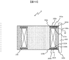
- FIG. 10 is a cross-sectional view showing an axial type rotating electrical machine 1 according to another embodiment to which a second conductive member is added.
- FIG. 11 is a perspective view of the stator unit 115 constituting the stator 100 and the periphery thereof.
- the second conductive member 160a is disposed between the first conductive member 140a and a rotor (not shown) disposed in the axial direction.
- the second conductive member 160b is disposed between the first conductive member 140b and a rotor (not shown) disposed in the axial direction.
- the second conductive member 160a includes a first contact surface 161a that contacts the surface 146a opposite to the surface of the first conductive member 140a that contacts the flange 121a, and a second contact surface 162a that contacts the inner wall of the housing 300. And form.
- the housing 300 is grounded.
- the second conductive member 160b has the same configuration.
- the first conductive member 140a and the second conductive member 160a are in contact with each other on the surface, it is easy to obtain conduction. Further, the heat radiation path of the internal parts of the axial type rotating electrical machine is mainly provided in the direction from the inner wall of the housing 300 to the outer wall. Therefore, by using the second conductive member 160a of the present embodiment, the heat generated in the stator can be transmitted to the inner wall of the housing 300 via the second conductive member 160a, and the heat dissipation of the axial type rotating electrical machine can be improved. Can be improved.
- the core 110 is molded with the resin 150, a plurality of means for grounding the core 110 which are arranged in the circumferential direction and are electrically independent from each other are required. Therefore, the second conductive member 160a forms a third contact surface 163a that contacts the core 110.
- the third contact surface 163b has the same configuration.
- the second conductive member 160a that is continuous 360 ° in a ring shape is assumed, but the shape of the second conductive member 160a is arbitrary. It may be divided into a plurality in the circumferential direction. Individual second conductive members 160a may be separated.
- the second conductive member 160a is preferably made of a nonmagnetic conductor such as aluminum. Thereby, the leakage magnetic flux to the 2nd electroconductive member 160a reduces, and the output and efficiency of a rotary electric machine can be improved.
- the second conductive member 160a and the core 110 are electrically connected by another means, the second conductive member 160a may be provided on any one of the axial end surfaces.
- the second conductive member 160a is made of a high thermal conductor such as aluminum, an effect of improving the heat dissipation of the stator can be obtained. In this case, the heat dissipation effect can be doubled by providing the both ends of the stator.
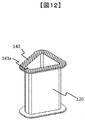
- FIG. 12 is a perspective view of a stator unit showing another example of the first conductive member applicable to the present embodiment explained so far.
- the stator unit has a cutting portion 143a so that the first conductive member 143 disposed around the core tip is discontinuous in the circumferential direction.
- the first conductive member 144 may be meshed. Such an arrangement pattern of the first conductive member 144 can be manufactured by a pattern during printing and vapor deposition. Alternatively, the first conductive member 144 can be discontinuously grounded by providing irregularities corresponding to the pattern on the conductor installation surface of the bobbin in advance.
Abstract
部品点数を増加することなく信頼性に優れた軸受電食対策技術を提供する。本発明の回転電機は、固定子(100)と、前記固定子を貫通する軸(400)と、軸方向に空隙を介して前記固定子と対向する回転子(200a,200b)と、前記固定子を保持するハウジング(300)と、を備え、前記固定子は、接地される第1導電部材(140a, 140b)とコア(110)とボビン(120)と当該ボビンを巻く巻線(130)とを有する固定子ユニットを周方向に複数個備え、前記ボビンは、前記巻線と前記回転子との間に形成される鍔部(121a,121b)を有し、前記第1導電部材は、前記鍔部と前記回転子との間に配置されかつ前記コアと接触し、前記軸方向から投影した場合に、前記巻線は、前記ボビンに巻かれた部分の射影部(131)が前記鍔部の射影部(128)よりも内側になるように形成され、前記第1導電部材は、当該第1導電部材の射影部(148)が前記鍔部の射影部に包含されるように形成される。
Description
本発明は、回転電機に係り、特にアキシャル型回転電機に関する。
近年、省エネルギーの観点から、インバータ電源を用いた回転電機の可変速運転が盛んになっている。インバータ駆動時に顕著となる課題の1つに、軸受電食がある。この対策として、巻線から回転子へのインバータコモンモード電圧の静電結合を導電材で遮蔽することで、回転子に誘起されるコモンモード電圧(以下、軸電圧)を低減し、回転子を支える軸受の内輪と外輪の間に加わる電圧を低減して、軸受の電食を防止する方法がある。
ところで、近年、アキシャル型の回転電機が注目されている。本回転電機は、円盤状の回転子と固定子が対向して配置された構造を有し、回転電機の薄型、扁平化に有利な構成である。また、本回転電機においては、固定子を軸方向から2枚の回転子で挟み込んだダブルロータ型で構成することも可能である。一般的なダブルロータ型の回転電機は、独立したコアに巻線を巻回したものを周方向に複数個配置し、樹脂でモールドした固定子と、周方向に複数配置した永久磁石をヨークに接続した回転子から構成されている。モータのトルクは、回転子と固定子の対向面であるギャップ面積に比例するが、ダブルロータ型は、体格あたりのギャップ面積を大きくできるので回転電機の高出力化、高効率化に有効である。アモルファスやファインメット、ナノクリスタルといった低損失を特徴とした新磁性材料の適用にも有効な構造である。これらの新磁性材は、いずれも硬く脆いため加工が難しい。ダブルロータ型の回転電機は、固定子コアをオープンスロットとすることで、略直方体という非常に単純な形状でコアを構成できる。このため、上記磁性材を簡単な加工でコア形状に加工することが可能である。
一方、上記のようなダブルロータ構造の場合、オープンスロット構造のため、巻線と回転子の対向面積が大きく、かつ、樹脂で覆われているためコアが接地されていない場合が多い。この場合、巻線と回転子の静電結合が強くなり、軸受にコモンモード電圧が誘起されやすい。
特許文献1、2には、固定子巻線と回転子間を遮蔽する構造が開示されている。巻線と回転子間を遮蔽することで、軸電圧を低減し軸受電食を抑制することができる。特許文献1では、短冊状に加工した非磁性導体板の表面全体を絶縁体で包み込んだ絶縁スリーブを、スロット開口部に挿入し、非磁性導体板と接地されたコアを導通させている。また、特許文献2では、巻線の表面に絶縁体を配置し、その上に磁束の流れに垂直な方向に導電体と絶縁体を交互に配置している。絶縁体として、巻線を巻回するボビンを利用する方法も開示している。
特許文献1は、巻線と回転子間を遮蔽するために、既存の構成に絶縁スリーブを追加する必要があり、対策前後で部品点数が増加する。一方で、特許文献2のボビン表面に導電体を直接設置する方法は、部品点数の増加を伴わない。ただし、導電体が表面に露出しているため、絶縁距離を確実に確保しないと、巻線との間で絶縁破壊を起こし、回転電機を損傷する恐れがある。さらに、いずれの公開技術も、ダブルロータ型のアキシャル型回転電機に適用した場合、導電体の接地構造が課題となる。
以上より、本発明では、部品点数を増加することなく信頼性に優れた軸受電食対策技術を提供するとともに、コアが絶縁されたダブルロータ型のアキシャル型回転電機にも対応した技術を提供する。
上記課題を達成するために本発明の回転電機は、固定子と、前記固定子を貫通する軸と、軸方向に空隙を介して前記固定子と対向する回転子と、前記固定子を保持するハウジングと、を備え、前記固定子は、接地される第1導電部材とコアとボビンと当該ボビンを巻く巻線とを有する固定子ユニットを周方向に複数個備え、前記ボビンは、前記巻線と前記回転子との間に形成される鍔部を有し、前記第1導電部材は、前記鍔部と前記回転子との間に配置されかつ前記コアと接触し、前記軸方向から投影した場合に、前記巻線は、前記ボビンに巻かれた部分の射影部が前記鍔部の射影部よりも内側になるように形成され、前記第1導電部材は、当該第1導電部材の射影部が前記鍔部の射影部に包含されるように形成される。
本発明の回転電機は、接地された導電体により巻線と回転子との間の静電結合が遮蔽されるため、軸電圧を低減し、軸受電食を抑制することができる。また、導電体と巻線との距離を確保できるため、絶縁破壊に対する信頼性を確保できる。
以下、本発明の実施例について図面を参照して説明する。
図1は、本実施形態に係るアキシャル型回転電機の斜視図である。図2は、図1の矢印A方向から見た断面図である。図3は、固定子100を構成する固定子ユニット115の斜視図である。図4は、図1の一点鎖線Cで囲まれた部分の拡大図である。
回転電機1は、固定子100と、固定子100を軸方向から挟み込むように配置された2枚の回転子200a及び200bとからなる。固定子100は、軟磁性体で構成されたコアと、コア110を囲むボビン120と、ボビン120を巻回す巻線130とを有する固定子ユニット115を周方向に複数個配置する。さらに固定子100は、樹脂150でハウジング300と一体でモールドして構成される。つまり、ハウジング300は、固定子100を保持する。
回転子200aは、軟磁性体で構成されたヨーク220aと、周方向に複数配置されかつヨーク220aに接続した永久磁石210aとから構成される。回転子200bは、軟磁性体で構成されたヨーク220bと、周方向に複数配置されかつヨーク220bに接続した永久磁石210aとから構成される。回転子200a及び回転子200bは、軸受500を介してハウジング300に回転自在に固定された軸400に接続されている。
ボビン120は、コア110を収納する収納空間を形成する筒部122と、筒部122の軸方向の一方の端面に接続されかつ回転子200aと巻線130との間に突出した鍔部121aと、筒部122の軸方向の他方の端面に接続されかつ回転子200bと巻線130との間に突出した鍔部121bと、から構成される。
第1導電部材140aは、鍔部121aの回転子200aと対向する面に配置されかつコア110と接触する。第1導電部材140bは、鍔部121bの回転子200bと対向する面に配置されかつコア110と接触する。また第1導電部材140a及び第1導電部材140bは接地されている。
図2に示されるように、軸方向と平行な矢印Bから投影した場合に、巻線130は、ボビン120に巻かれた部分の射影部131が鍔部121a又は鍔部121bの射影部128よりも内側になるように形成される。また第1導電部材140a又は第1導電部材140bは、第1導電部材140a又は第1導電部材140bの射影部148が鍔部121a又は鍔部121bの射影部128に包含されるように形成される。このように構成されることにより、図4に示されるように、第1導電部材140aと巻線130との最短の直線距離124が、第1導電部材140aと巻線130との最短の沿面距離(距離123aと距離123bとの和)よりも小さくなる。
次に本実施形態のアキシャル型回転電機の動作を説明する。ここでは、モータ動作例について説明する。インバータや交流電源(図示なし)を用い巻線130に交流電流を通電する。これにより、固定子100表面に交番磁界が形成される。この交番磁界と永久磁石210a及び永久磁石210bによる回転子200a及び回転子200bの静磁界が吸引、反発することで、回転子200a及び回転子200bが回転しトルクを発生する。
次に本実施形態のアキシャル型回転電機の効果を説明する。巻線130と回転子200a又は回転子200bとの間は、接地された第1導電部材140aにより遮蔽されている。このため、巻線130と回転子200a又は回転子200bとの間に電位差が生じることが抑制される。これにより、軸受500の内外輪間の電位差も低減する。結果として、軸受500内の油膜破壊による軸電流の発生、これによる軸受500の電食の発生を抑制することができる。
また、鍔部121aの表面に配置された第1導電部材140aと巻線130とは、鍔部121aの肉厚(図4に示される距離123a)と鍔部121aの先端と巻線130との距離分の沿面距離(図4に示される距離123b)を介して配置されている。これにより、第1導電部材140aと巻線130との間との電気的な絶縁性が確保され、第1導電部材140aと巻線130との間で絶縁破壊することを抑制できる。
なお、本実施形態では、固定子100の両端に2枚の回転子200a及び回転子200bを配置した例を示したが、バックヨークをもつ1つの固定子に1枚の回転子が対向したタイプのアキシャル型回転電機であっても良い。また、バックヨークをもつ2つの固定子100で、1つの回転子を挟み込んだタイプのアキシャル型回転電機であってもよい。
なお第1導電部材140a及び第1導電部材140bは、非磁性材料で構成されることが望ましい。これにより、第1導電部材140a及び第1導電部材140bへの漏れ磁束を抑制し回転電機の出力、効率を向上できる。第1導電部材140a及び第1導電部材140bは、メッキや蒸着、接着などの後工程によりボビン120に設置する。または、ボビン120と一体で成形しても良い。第1導電部材140a及び第1導電部材140bは、ボビン120の鍔部121a又は鍔部121bの表面でなく、鍔部の内部に埋め込まれていても良い。
図5は、第1導電部材の他の実施形態を示したアキシャル型回転電機の断面図である。図1ないし図4と重複する構造、動作、効果の説明は省略する。図6は、固定子100を構成する固定子ユニット115の斜視図である。図7は、図5の一点鎖線Cで囲まれた部分の拡大図である。
本実施形態においては、第1導電部材141aは、この第1導電部材141aの射影部132が鍔部121aの射影部148よりも内側になるように形成される。また第1導電部材141bは、この第1導電部材141bの射影部132が鍔部121bの射影部148よりも内側になるように形成される。
つまり図7に示されるように、鍔部121aの先端と第1導電部材141aとの間に距離123cが設けられる。これにより、鍔部121a及び鍔部121bの先端の近傍まで巻線130を巻回することができ、固定子空間を有効に活用することができる。
図8は、第1導電部材の他の実施形態を示したアキシャル型回転電機の断面図である。
図1ないし図4と重複する構造、動作、効果の説明は省略する。
図1ないし図4と重複する構造、動作、効果の説明は省略する。
第1導電部材142は、筒部122とコア110との間の空間まで形成される。さらに第1導体部材142は、筒部122と対向するコア110のコア面111と接触する。これにより、第1導電部材142は、筒部122とコア110との間に強固に固定され、コア110との接続信頼性を向上させることができる。
図9は、コアの他の実施形態を示したアキシャル型回転電機の断面図である。図1ないし図4と重複する構造、動作、効果の説明は省略する。
コア110は、第1導電部材140aと軸方向に配置される回転子(不図示)との間に形成されるコア側鍔部112aを有する。そしてコア側鍔部112aは、鍔部121aと接触する第1導電部材140aの面とは反対側の面145aと接触する。またコア110は、第1導電部材140bと軸方向に配置される回転子(不図示)との間に形成されるコア側鍔部112bを有する。そしてコア側鍔部112bは、鍔部121bと接触する第1導電部材140bの面とは反対側の面145bと接触する。なお本実施形態ではコア110が接地されているが、第1導電部材140aが接地されていてよい。これにより、第1導電部材140a又は第1導電部材140bは、鍔部121a又は鍔部121bとコア側鍔部112a又はコア側鍔部112bコア110との間に強固に固定され、コア110との接続信頼性を向上させることができる。
図10は、第2導電部材を追加した他の実施形態に係るアキシャル型回転電機1を示す断面図である。図11は、固定子100を構成する固定子ユニット115及びその周辺の斜視図である。
第2導電部材160aは、第1導電部材140aと軸方向に配置された回転子(不図示)との間に配置される。第2導電部材160bは、第1導電部材140bと軸方向に配置された回転子(不図示)との間に配置される。そして第2導電部材160aは、鍔部121aと接触する第1導電部材140aの面とは反対側の面146aと接触する第1接触面161aと、ハウジング300の内壁と接触する第2接触面162aと、を形成する。ハウジング300は、接地されている。第2導電部材160bも同様の構成である。
これにより、第1導電部材140aと第2導電部材160aは、面で接触するため導通も取り易くなる。またアキシャル型回転電機の内部部品の放熱経路は、主にハウジング300の内壁から外壁に向かう方向に設けられる。そこで本実施形態の第2導電部材160aを用いることにより、固定子で発生した熱を、第2導電部材160aを介してハウジング300の内壁に伝達することができ、アキシャル型回転電機の放熱性を向上させることができる。
また、コア110が樹脂150でモールドされているため、周方向に複数個配置され個々が電気的にも独立したコア110を接地するための手段が別途必要となる。そこで第2導電部材160aは、コア110と接触する第3接触面163aを形成する。第3接触面163bも同様の構成である。これにより、第1導電部材140aとコア110の接地を同時に確保することが可能であり、部品点数の削減、および、構造の簡略化を図ることができ、接地するための電気的接続の信頼性を向上させることができる。
なお図10及び図11において、リング状に360°連続した第2導電部材160aを想定していたが、第2導電部材160aの形状は任意である。周方向に複数に分割されていても良い。個々の第2導電部材160aが分離していても良い。第2導電部材160aは、アルミなどの非磁性の導電体で構成することが望ましい。これにより、第2導電部材160aへの漏れ磁束が減少し、回転電機の出力、効率を向上することができる。なお、第2導電部材160aとコア110が別の手段で導通している場合、第2導電部材160aは、軸方向端面の任意の一方に設ければ良い。ただし、第2導電部材160aをアルミのような高熱伝導体で構成した場合、固定子の放熱性を向上させる効果もでる。この場合、固定子の両端面に設けることで放熱効果を倍増することができる。
図12は、これまで説示した本実施形態に適用できる第1導電部材の他の実施例を示す固定子ユニットの斜視図である。
固定子ユニットは、コア先端の周囲に配置される第1導電部材143が周方向で不連続となるよう、切断部143aを形成している。これにより、必要最小限の遮蔽面積の減少により、コアを中心とした、第1導電部材143に流れる渦電流のループを遮断し、損失の発生を抑制することができ、回転電機の出力、効率を向上することができる。
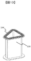
なお、本実施形態では、周方向の一か所を切断しているが、遮蔽面積が大幅に減少しない程度に、かつ、第1導電部材が分離しないように、複数個所にスリットを設けても良い。さらには、図13に示すように、第1導電部材144をメッシュ状にしても良い。このような第1導電部材144の配置パターンは、印刷、蒸着時のパターンにより製作することができる。または、あらかじめボビンの導電体設置面にパターンに対応した凹凸を設け、第1導電部材144を不連続に接地することもできる。
1・・・回転電機、100・・・固定子、110・・・コア、111・・・コア面、112a・・・コア側鍔部、115・・・固定子ユニット、120・・・ボビン、121a・・・鍔部、121b・・・鍔部、122・・・筒部、123a・・・距離、123b・・・距離、123c・・・距離、124・・・直線距離、128・・・射影部、130・・・巻線、131・・・射影部、132・・・射影部、140a・・・第1導電部材、140b・・・第1導電部材、141a・・・第1導電部材、141b・・・第1導電部材、142・・・第1導電部材、143・・・第1導電部材、144・・・第1導電部材、143a・・・切断部、145a・・・面、145b・・・面、146a・・・面、146b・・・面、148・・・射影部、150・・・樹脂、160a・・・第2導電部材、160b・・・第2導電部材、161a・・・第1接触面、162a・・・第2接触面、163a・・・第3接触面、163b・・・第3接触面、200a・・・回転子、200b・・・回転子、210a・・・永久磁石、210b・・・永久磁石、220a・・・ヨーク、220b・・・ヨーク、300・・・ハウジング、400・・・軸、500・・・軸受
Claims (6)
- 固定子と、
前記固定子を貫通する軸と、
軸方向に空隙を介して前記固定子と対向する回転子と、
前記固定子を保持するハウジングと、を備え、
前記固定子は、接地される第1導電部材とコアとボビンと当該ボビンを巻く巻線とを有する固定子ユニットを周方向に複数個備え、
前記ボビンは、前記巻線と前記回転子との間に形成される鍔部を有し、
前記第1導電部材は、前記鍔部と前記回転子との間に配置されかつ前記コアと接触し、 前記軸方向から投影した場合に、前記巻線は、前記ボビンに巻かれた部分の射影部が前記鍔部の射影部よりも内側になるように形成され、
前記第1導電部材は、当該第1導電部材の射影部が前記鍔部の射影部に包含されるように形成される回転電機。 - 請求項1に記載の回転電機であって、
前記第1導電部材は、当該第1導電部材の射影部が前記鍔部の射影部よりも内側になるように形成される回転電機。 - 請求項1又は2に記載のいずれかのアキシャル型回転電機であって、
前記ボビンは、前記コアを収納する空間を形成する筒部を有し、
前記第1導電部材は、前記筒部と前記コアとの間の空間まで形成され、
さらに前記第1導体部材は、前記筒部と対向する前記コアの面と接触するアキシャル型回転電機。 - 請求項1ないし3に記載のいずれかのアキシャル型回転電機であって、
前記コアは、前記第1導電部材と前記回転子との間に形成されるコア側鍔部を有し、
前記コア側鍔部は、前記鍔部と接触する前記第1導電部材の面とは反対側の面と接触するアキシャル型回転電機。 - 請求項1ないし4に記載のいずれかのアキシャル型回転電機であって、
前記第1導電部材と前記回転子との間に配置される第2導電部材を備え、
前記ハウジングは、接地され、
前記第2導電部材は、前記鍔部と接触する前記第1導電部材の面とは反対側の面と接触する第1接触面と、前記ハウジングの内壁と接触する第2接触面と、を形成するアキシャル型回転電機。 - 請求項5に記載のアキシャル型回転電機であって、
前記第2導電部材は、前記コアと接触する第3接触面を形成するアキシャル型回転電機。
Priority Applications (1)
| Application Number | Priority Date | Filing Date | Title |
|---|---|---|---|
| US14/654,713 US20150349588A1 (en) | 2013-02-08 | 2014-01-24 | Rotating Electrical Machine |
Applications Claiming Priority (2)
| Application Number | Priority Date | Filing Date | Title |
|---|---|---|---|
| JP2013-022803 | 2013-02-08 | ||
| JP2013022803A JP5851432B2 (ja) | 2013-02-08 | 2013-02-08 | 回転電機 |
Publications (1)
| Publication Number | Publication Date |
|---|---|
| WO2014123003A1 true WO2014123003A1 (ja) | 2014-08-14 |
Family
ID=51299600
Family Applications (1)
| Application Number | Title | Priority Date | Filing Date |
|---|---|---|---|
| PCT/JP2014/051432 WO2014123003A1 (ja) | 2013-02-08 | 2014-01-24 | 回転電機 |
Country Status (3)
| Country | Link |
|---|---|
| US (1) | US20150349588A1 (ja) |
| JP (1) | JP5851432B2 (ja) |
| WO (1) | WO2014123003A1 (ja) |
Cited By (1)
| Publication number | Priority date | Publication date | Assignee | Title |
|---|---|---|---|---|
| WO2019077983A1 (ja) * | 2017-10-19 | 2019-04-25 | 株式会社日立産機システム | アキシャルギャップ型回転電機 |
Families Citing this family (6)
| Publication number | Priority date | Publication date | Assignee | Title |
|---|---|---|---|---|
| JP6547006B2 (ja) * | 2015-11-24 | 2019-07-17 | 株式会社日立産機システム | アキシャルギャップ型回転電機及び回転電機用固定子 |
| US10992203B2 (en) * | 2016-05-18 | 2021-04-27 | Hitachi Industrial Equipment Systems Co., Ltd. | Axial gap type rotary electric machine |
| WO2018142463A1 (ja) * | 2017-01-31 | 2018-08-09 | 株式会社日立産機システム | アキシャルギャップ型回転電機 |
| DE102017118125A1 (de) * | 2017-08-09 | 2019-02-14 | Ebm-Papst Mulfingen Gmbh & Co. Kg | Vorrichtung zur Reduzierung von schädlichen Lagerspannungen |
| WO2020042912A1 (zh) * | 2018-08-31 | 2020-03-05 | 浙江盘毂动力科技有限公司 | 一种分段铁芯以及盘式电机 |
| JP7331013B2 (ja) * | 2018-12-18 | 2023-08-22 | 住友電気工業株式会社 | コア、ステータ、及び回転電機 |
Citations (4)
| Publication number | Priority date | Publication date | Assignee | Title |
|---|---|---|---|---|
| JP2010088142A (ja) * | 2008-09-29 | 2010-04-15 | Daikin Ind Ltd | インシュレータ及び電機子コア |
| JP2012005307A (ja) * | 2010-06-21 | 2012-01-05 | Hitachi Industrial Equipment Systems Co Ltd | 回転電機 |
| JP2013005464A (ja) * | 2011-06-10 | 2013-01-07 | Denso Corp | 回転電機 |
| JP2014017915A (ja) * | 2012-07-06 | 2014-01-30 | Hitachi Ltd | アキシャルギャップ型回転電機 |
Family Cites Families (3)
| Publication number | Priority date | Publication date | Assignee | Title |
|---|---|---|---|---|
| JP5567311B2 (ja) * | 2009-10-22 | 2014-08-06 | 株式会社日立産機システム | アキシャルギャップモータ、圧縮機、モータシステム、および発電機 |
| JP5916591B2 (ja) * | 2012-12-07 | 2016-05-11 | 株式会社日立製作所 | アキシャルギャップモータ |
| CN105684269A (zh) * | 2013-11-22 | 2016-06-15 | 株式会社日立制作所 | 轴向间隙型旋转电机 |
-
2013
- 2013-02-08 JP JP2013022803A patent/JP5851432B2/ja active Active
-
2014
- 2014-01-24 WO PCT/JP2014/051432 patent/WO2014123003A1/ja active Application Filing
- 2014-01-24 US US14/654,713 patent/US20150349588A1/en not_active Abandoned
Patent Citations (4)
| Publication number | Priority date | Publication date | Assignee | Title |
|---|---|---|---|---|
| JP2010088142A (ja) * | 2008-09-29 | 2010-04-15 | Daikin Ind Ltd | インシュレータ及び電機子コア |
| JP2012005307A (ja) * | 2010-06-21 | 2012-01-05 | Hitachi Industrial Equipment Systems Co Ltd | 回転電機 |
| JP2013005464A (ja) * | 2011-06-10 | 2013-01-07 | Denso Corp | 回転電機 |
| JP2014017915A (ja) * | 2012-07-06 | 2014-01-30 | Hitachi Ltd | アキシャルギャップ型回転電機 |
Cited By (3)
| Publication number | Priority date | Publication date | Assignee | Title |
|---|---|---|---|---|
| WO2019077983A1 (ja) * | 2017-10-19 | 2019-04-25 | 株式会社日立産機システム | アキシャルギャップ型回転電機 |
| JP2019075952A (ja) * | 2017-10-19 | 2019-05-16 | 株式会社日立産機システム | アキシャルギャップ型回転電機 |
| JP7007150B2 (ja) | 2017-10-19 | 2022-01-24 | 株式会社日立産機システム | アキシャルギャップ型回転電機 |
Also Published As
| Publication number | Publication date |
|---|---|
| US20150349588A1 (en) | 2015-12-03 |
| JP5851432B2 (ja) | 2016-02-03 |
| JP2014155313A (ja) | 2014-08-25 |
Similar Documents
| Publication | Publication Date | Title |
|---|---|---|
| JP5851432B2 (ja) | 回転電機 | |
| JP5965228B2 (ja) | アキシャルギャップ型回転電機 | |
| JP5879121B2 (ja) | アキシャルギャップ回転電機 | |
| JP5268711B2 (ja) | 電動機及び圧縮機及び空気調和機及び電気掃除機 | |
| JP5851365B2 (ja) | 回転電機 | |
| JP5564341B2 (ja) | 回転電機 | |
| JP5314908B2 (ja) | 回転電機の固定子および回転電機 | |
| JP5885179B2 (ja) | 機電一体型回転電機 | |
| JP5696694B2 (ja) | 回転電機のステータ | |
| WO2014208110A1 (ja) | アキシャル型回転電機 | |
| TW201541809A (zh) | 軸向氣隙型旋轉電機 | |
| JP7286805B2 (ja) | 固定子および回転電機 | |
| JP2012130157A (ja) | 電動機 | |
| JP2008236866A (ja) | 永久磁石埋め込み型回転電機の回転子及び永久磁石埋め込み型回転電機 | |
| KR101636330B1 (ko) | 플럭스 필터링 기능을 갖는 회전자 및 그를 포함하는 동기형 모터 | |
| JP2015091146A (ja) | 集中巻回転電機のステータ、及びこれを備えた回転電機 | |
| JP6771708B1 (ja) | 回転電機 | |
| WO2022219923A1 (ja) | 回転子及び電動機 | |
| TWI761871B (zh) | 旋轉電機 | |
| JP7337001B2 (ja) | アキシャルギャップ型回転電機 | |
| JP6451886B2 (ja) | モータ | |
| JP6294426B2 (ja) | モータ | |
| JP6298133B2 (ja) | モータ | |
| JP2014054044A (ja) | ステータ及びこのステータを備えた回転電機 | |
| JPWO2022219923A5 (ja) |
Legal Events
| Date | Code | Title | Description |
|---|---|---|---|
| 121 | Ep: the epo has been informed by wipo that ep was designated in this application |
Ref document number: 14748778 Country of ref document: EP Kind code of ref document: A1 |
|
| WWE | Wipo information: entry into national phase |
Ref document number: 14654713 Country of ref document: US |
|
| NENP | Non-entry into the national phase |
Ref country code: DE |
|
| 122 | Ep: pct application non-entry in european phase |
Ref document number: 14748778 Country of ref document: EP Kind code of ref document: A1 |