WO2014122956A1 - ラムダセンサ予熱制御方法及びラムダセンサ駆動制御装置 - Google Patents
ラムダセンサ予熱制御方法及びラムダセンサ駆動制御装置 Download PDFInfo
- Publication number
- WO2014122956A1 WO2014122956A1 PCT/JP2014/050619 JP2014050619W WO2014122956A1 WO 2014122956 A1 WO2014122956 A1 WO 2014122956A1 JP 2014050619 W JP2014050619 W JP 2014050619W WO 2014122956 A1 WO2014122956 A1 WO 2014122956A1
- Authority
- WO
- WIPO (PCT)
- Prior art keywords
- lambda sensor
- preheating
- period
- control
- internal heater
- Prior art date
- Legal status (The legal status is an assumption and is not a legal conclusion. Google has not performed a legal analysis and makes no representation as to the accuracy of the status listed.)
- Ceased
Links
Images


Classifications
-
- G—PHYSICS
- G01—MEASURING; TESTING
- G01N—INVESTIGATING OR ANALYSING MATERIALS BY DETERMINING THEIR CHEMICAL OR PHYSICAL PROPERTIES
- G01N27/00—Investigating or analysing materials by the use of electric, electrochemical, or magnetic means
- G01N27/26—Investigating or analysing materials by the use of electric, electrochemical, or magnetic means by investigating electrochemical variables; by using electrolysis or electrophoresis
- G01N27/403—Cells and electrode assemblies
- G01N27/406—Cells and probes with solid electrolytes
- G01N27/4067—Means for heating or controlling the temperature of the solid electrolyte
Definitions
- the present invention relates to a lambda sensor that detects an oxygen concentration in an exhaust gas of a vehicle and the like, and more particularly to a device that improves the reliability of preheating control.
- preheating control of the heater is necessary before the oxygen concentration detection operation, but the reliability, stability, etc. of such preheating control are improved.
- Various control methods and devices have been proposed and put to practical use for the purpose. For example, paying attention to the correlation between the heater resistance value and the temperature, the heater resistance value is detected, and it is determined from the resistance value whether or not the center has reached a temperature sufficient for the detection operation. Is disclosed (see, for example, Patent Document 1).
- the pulse width has a rectangular pulse voltage waveform.
- JP 2009-288082 A (page 4-13, FIG. 1 to FIG. 10)
- the present invention has been made in view of the above circumstances, and it is possible to reliably secure an effective voltage desired in the preheating control and realize a highly reliable preheating control and a lambda sensor preheating control method.
- a device is provided.
- a lambda sensor preheating control method comprises A lambda sensor preheating control method in a lambda sensor preheating control device configured to apply a pulse voltage by PWM control to an internal heater of a lambda sensor and preheat the internal heater,
- the repetition period of the pulse voltage in the preheating period is made larger than the repetition period in normal energization after the end of the preheating period, and the effective value of the applied voltage of the internal heater can be secured to a desired value. is there.
- the lambda sensor drive control device includes: An arithmetic control unit for generating and outputting a control signal for controlling energization to the internal heater of the lambda sensor;
- a lambda sensor drive control device comprising an energization drive unit configured to energize the internal heater by applying a pulse voltage by PWM control based on a control signal of the arithmetic control unit;
- the arithmetic control unit is The repetition period of the pulse voltage in the preheating period is set to be larger than the repetition period in the normal energization after the preheating period, and the effective value of the applied voltage of the internal heater can be secured to a desired value. It will be.
- the repetition period of the pulse voltage in the preheating period is set to be relatively longer than that in the normal energization period, and the effective value of the pulse voltage applied to the internal heater in the preheating period is set to the original value as much as possible. Since energization is performed in close proximity, it is possible to prevent insufficient preheating. On the other hand, during the normal energization period, the normal repetition period is set to reduce thermal stress caused by increasing the repetition period. As a result, it is possible to achieve preheating control with higher reliability and stability than in the prior art.
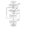
- FIG. 1 It is a block diagram which shows the structural example of the lambda sensor drive control apparatus in embodiment of this invention. It is a subroutine flowchart which shows the process sequence of the lambda sensor preheating control in embodiment of this invention applied to the lambda sensor drive control apparatus shown by FIG. It is a wave form diagram showing typically an example of change of a repetition cycle of a pulse voltage applied to an internal heater in lambda sensor preheating control in an embodiment of the invention.
- the lambda sensor drive control device uses an electronic control unit (indicated as “ECU” in FIG. 1) 100 that controls the operation of a vehicle.
- the detection unit 51, the calculation control unit (indicated as “CPU” in FIG. 1) 52, and the energization drive unit 53 are configured as main components.
- the battery voltage detection unit 51 detects the voltage of a vehicle battery (not shown) and supplies the detected voltage to the calculation control unit 52.
- the battery voltage detection unit 51 in the embodiment of the present invention mainly includes first and second resistors for detection 2 and 3 connected in series between a vehicle battery (not shown) and a ground, and a buffer amplifier 4. It is configured as a component.
- the connection point between the first detection resistor 2 and the second detection resistor 3 is connected to the input stage of the buffer amplifier 4, and the divided voltage corresponding to the voltage Vb of the vehicle battery is a buffer amplifier. 4 is input to the arithmetic control unit 52 via the lambda sensor drive control process and the like in the arithmetic control unit 52.
- the arithmetic control unit 52 includes, for example, a storage element (not shown) such as a RAM or a ROM centering on a microcomputer (not shown) or an ASIC (Application Specific Integrated Circuit) having a known / known configuration.
- a storage element such as a RAM or a ROM centering on a microcomputer (not shown) or an ASIC (Application Specific Integrated Circuit) having a known / known configuration.
- an interface circuit (not shown) for outputting a control signal to the energization driving unit 53 is configured as a main component.
- lambda sensor drive control processing such as duty ratio calculation of the pulse voltage applied to the lambda sensor 1 is executed as in the conventional case, and the lambda sensor preheating control processing in the embodiment of the present invention is performed. It is supposed to be executed.
- the energization drive unit 53 includes a drive circuit (denoted as “DRV” in FIG. 1) 53 a and an energization control semiconductor element 5, and is energized by the drive circuit 53 a based on a control signal from the arithmetic control unit 52.
- the energization control of the internal heater 1 a of the lambda sensor 1 is performed by controlling the control semiconductor element 5.
- a MOS FET or the like is used as the energization control semiconductor element 5.
- the drain of the semiconductor element 5 is connected to one end of the internal heater 1 a of the lambda sensor 1, the source is connected to the ground, and the gate is connected to the drive circuit 53 a. It is connected to the output stage.
- a battery voltage Vb of a vehicle battery (not shown) is applied to the other end of the internal heater 1a.
- Vb battery voltage
- the conduction / non-conduction of the energization control semiconductor element 5 is controlled according to the gate voltage as a control signal applied from the drive circuit 53a, and accordingly the energization of the internal heater 1a can be controlled. ing.
- the lambda sensor 1 is, for example, a wide band lambda sensor or the like. As is well known, the lambda sensor 1 has an internal heater 1a. In order to obtain a stable detection signal, preheating is performed by the internal heater 1a before obtaining the detection signal. ing. In FIG. 1, the output portion of the detection signal corresponding to the oxygen concentration detected by the lambda sensor 1 is not shown.
- the subroutine flowchart shown in FIG. 2 is one subroutine process that is executed together with the drive control process of the lambda sensor 1 that is executed in the arithmetic control unit 52 as in the prior art. Further, it is assumed that the series of processes shown in FIG. 2 is started when a vehicle engine (not shown) is started.
- the post-startup elapsed time tdr which is a variable representing the elapsed time from the start of the vehicle engine, is initialized to zero (see step S102 in FIG. 2).
- a so-called timing program which has been well known in the past, is started to be executed after the vehicle engine is activated, and the elapsed time after activation from the activation is counted. .
- step S104 it is determined whether or not the elapsed time after starting tdr is less than a predetermined preheating period (see step S104 in FIG. 2), and it is determined that the elapsed time after starting tdr is less than a predetermined preheating period. If it is determined (in the case of YES), energization for preheating based on the preheating cycle setting is continued, assuming that it is still a period for performing preheating control (see step S106 in FIG. 2).
- the energization control of the lambda sensor 1, that is, the energization control of the internal heater 1 a is basically the same as in the prior art.
- the preheating period of the heater 1a and the subsequent normal energizing period that is, the energizing period of the internal heater 1a in the period when the output signal of the lambda sensor 1 is used for engine drive control processing or the like, both are so-called PWM control. Is performed by applying a pulse voltage.
- the repetition cycle of the pulse voltage has been a constant value regardless of the preheating period or the normal energization period, but in the embodiment of the present invention, the repetition cycle of the normal energization period.
- a separate preheating cycle different from that (hereinafter referred to as “normal cycle” for convenience of description) is set. That is, in the embodiment of the present invention, the preheating cycle Tpre is set to a predetermined cycle longer than the normal cycle Tnr. Specifically, it is preferable to set the preheating cycle Tpre individually, taking into account the specifications of the vehicle device and the like, based on the test results and simulation results.
- the energization of the internal heater 1a is performed by applying a pulse voltage having a predetermined repetition cycle by controlling the energization control semiconductor element 5 on and off by the arithmetic control unit 52 via the drive circuit 53a as in the prior art.
- This is a power supply control by so-called PWM control.
- the pulse width of the pulse voltage is determined based on the duty ratio Dc calculated by the following formula 1 in the lambda sensor drive control process that is separately executed in the arithmetic control unit 52 as in the conventional case. It has come to be.
- the duty ratio Dc represents the ratio of the pulse width to the pulse repetition period T as a percentage.
- Vheff_tar is a target effective voltage that represents the voltage across the target of the internal heater 1a as an effective value
- Vb is an actual value of the battery voltage of a vehicle battery (not shown) detected by the battery voltage detector 51. (Actual battery voltage).
- the above-described duty ratio is a value to be set in order to obtain the target effective voltage Vheff_tar on the assumption that the pulse voltage waveform is a rectangular wave. However, if the actual pulse voltage waveform is a rectangular wave, the rise and fall times should be essentially zero, the on / off delay of various semiconductor elements in the drive circuit 53a, and the electrical characteristics of these semiconductor elements.
- the present inventor has found that the decrease in the duty ratio Dc has a correlation with the repetition period, and becomes remarkable as the repetition period becomes shorter.
- the lambda sensor 1 has been found to increase thermal stress.
- the inventor of the present application based on such knowledge, in the preheating period, by making the repetition period longer than the normal energization period, while reducing the reduction of the duty ratio Dc as much as possible, in the normal energization period, By setting a relatively short repetition period compared to the preheating period within the range in which the above-described thermal stress can be reduced as much as possible, it is possible to satisfy both the reduction of the duty ratio Dc and the reduction of the thermal stress. I came to a conclusion.
- the preheating cycle setting in the above-described step S106 is based on the test and research results of the present inventors. Therefore, it is preferable that the preheating cycle is set to a cycle in which the target effective voltage Vheff_tar of the internal heater 1a can be secured or an effective voltage closer to the target effective voltage Vheff_tar can be obtained.
- step S104 when it is determined in step S104 that the elapsed time after startup tdr is not less than the predetermined preheating period (in the case of NO), that is, the elapsed time after startup tdr exceeds the predetermined preheating period. If it is determined that a normal cycle is set, the energization of the internal heater 1a is shifted to a normal energization state (see step S108 in FIG. 2), and a series of processing is completed, and the main unit (not shown) Return to the routine.
- FIG. 3 schematically shows the change state of the repetition period during the preheating period and the normal energization period.
- the horizontal axis represents time
- the vertical axis represents time. The voltages at both ends of the internal heater 1a are respectively shown.
- step S104 is executed, and then step S108 is executed.
- the repetition period of the pulse voltage is a relatively long predetermined value. While the period Tpre is set, when the preheating period ends and the normal energization period (heating after completion of preheating) starts, the repetition period Tnr is set to a shorter value than the previous Tpre.
- the example of the change in the repetition cycle of the pulse voltage during the normal energization period shown in FIG. 3 is when the energization control of the internal heater 1a during the normal energization period is feedback control based on the heat generation temperature of the internal heater 1a. It is an example. Therefore, in the same figure, in the normal energization period, the pulse width changes from a relatively large state to the original pulse width.
- the feedback control based on the heat generation temperature of the internal heater 1a is a conventional energization control, and is necessary so that the heat generation temperature by the internal heater 1a is detected by a temperature sensor and becomes a desired temperature. According to the control, the pulse width of the pulse voltage applied to the internal heater 1a is changed.
Landscapes
- Chemical & Material Sciences (AREA)
- Life Sciences & Earth Sciences (AREA)
- Health & Medical Sciences (AREA)
- Physics & Mathematics (AREA)
- Chemical Kinetics & Catalysis (AREA)
- Electrochemistry (AREA)
- Molecular Biology (AREA)
- Analytical Chemistry (AREA)
- Biochemistry (AREA)
- General Health & Medical Sciences (AREA)
- General Physics & Mathematics (AREA)
- Immunology (AREA)
- Pathology (AREA)
- Combined Controls Of Internal Combustion Engines (AREA)
- Measuring Oxygen Concentration In Cells (AREA)
Abstract
予熱制御において所望される実効電圧を確実に確保し、信頼性の高い予熱制御を実現する。 演算制御部52により、予熱期間におけるパルス電圧の繰り返し周期Tpreが、予熱期間終了後の通常通電時における繰り返し周期Tnrに対して比較的大に設定されて、内部ヒータ1aの印加電圧の実効値が所望する値に確保可能とされる一方、予熱期間終了後の通常通電時には、パルス電圧の繰り返し周期Tnrは、従来通り比較的短い値に設定されるようになっている。
Description
本発明は、車両の排気ガス中等の酸素濃度を検出するラムダセンサに係り、特に、予熱制御の信頼性向上等を図ったものに関する。
センサ素子の温度を活性温度に維持する必要があるラムダセンサにあっては、酸素濃度の検出動作の前に、ヒータの予熱制御が必要であるが、かかる予熱制御の信頼性、安定性等を目的として種々の制御方法、装置が提案、実用化されている。
例えば、ヒータ抵抗値と温度との相関に着目し、ヒータ抵抗値を検出し、その抵抗値からセンタ全体が検出動作を行うに十分な温度に達したか否かを判定するようにした手法等が開示されている(例えば、特許文献1等参照)。
例えば、ヒータ抵抗値と温度との相関に着目し、ヒータ抵抗値を検出し、その抵抗値からセンタ全体が検出動作を行うに十分な温度に達したか否かを判定するようにした手法等が開示されている(例えば、特許文献1等参照)。
ところで、ラムダセンサのヒータへの通電は、所定幅のパルス電圧を所定の繰り返し周期で印加する方法が採られることが多いが、かかる方法にあって、パルス幅は、パルス電圧波形が矩形状であることを前提として定められるが、実際には、駆動回路の信号遅延や半導体素子の電気特性等に起因して、パルスの立ち上がり時間、立ち下がり時間に遅延が生じてしまう。
そのため、ヒータの印加電圧に要求される実効電圧が保てなくなり、予熱不足を招く虞がある。
そのため、ヒータの印加電圧に要求される実効電圧が保てなくなり、予熱不足を招く虞がある。
ところが、先に述べた従来技術のように、ヒータ抵抗値を検出するのみでヒータ温度の適否を判断するだけでは、規定通りの実効電圧が確保されているか否か判断することはできないため、要求される実効電圧を確実に保ち、予熱の不足を招かない予熱制御を行うことが困難という問題がある。また、ラムダセンサは、予熱の際に余分な水分を確実に排除する必要があるため、本来の実効電圧で十分な予熱が確保されないままで予熱を終えて、通常の加熱状態に移行した場合には、ラムダセンサの寿命に影響を与えかねないという問題もある。
本発明は、上記実状に鑑みてなされたもので、予熱制御において所望される実効電圧を確実に確保し、信頼性の高い予熱制御を実現することのできるラムダセンサ予熱制御方法及びラムダセンサ駆動制御装置を提供するものである。
上記本発明の目的を達成するため、本発明に係るラムダセンサ予熱制御方法は、
ラムダセンサの内部ヒータへPWM制御によるパルス電圧を印加し、前記内部ヒータの予熱を行うよう構成されてなるラムダセンサ予熱制御装置におけるラムダセンサ予熱制御方法であって、
予熱期間における前記パルス電圧の繰り返し周期を、予熱期間終了後の通常通電時における繰り返し周期に対して大とし、前記内部ヒータの印加電圧の実効値を所望する値に確保可能に構成されたものである。
また、上記翻発明の目的を達するため、本発明に係るラムダセンサ駆動制御装置は、
ラムダセンサの内部ヒータへの通電を制御する制御信号を生成、出力する演算制御部と、
前記演算制御部の制御信号に基づいて前記内部ヒータへPWM制御によるパルス電圧の印加により通電を行う通電駆動部とを具備してなるラムダセンサ駆動制御装置であって、
前記演算制御部は、
予熱期間における前記パルス電圧の繰り返し周期を、予熱期間終了後の通常通電時における繰り返し周期に対して大に設定し、前記内部ヒータの印加電圧の実効値を所望する値に確保可能に構成されてなるものである。
ラムダセンサの内部ヒータへPWM制御によるパルス電圧を印加し、前記内部ヒータの予熱を行うよう構成されてなるラムダセンサ予熱制御装置におけるラムダセンサ予熱制御方法であって、
予熱期間における前記パルス電圧の繰り返し周期を、予熱期間終了後の通常通電時における繰り返し周期に対して大とし、前記内部ヒータの印加電圧の実効値を所望する値に確保可能に構成されたものである。
また、上記翻発明の目的を達するため、本発明に係るラムダセンサ駆動制御装置は、
ラムダセンサの内部ヒータへの通電を制御する制御信号を生成、出力する演算制御部と、
前記演算制御部の制御信号に基づいて前記内部ヒータへPWM制御によるパルス電圧の印加により通電を行う通電駆動部とを具備してなるラムダセンサ駆動制御装置であって、
前記演算制御部は、
予熱期間における前記パルス電圧の繰り返し周期を、予熱期間終了後の通常通電時における繰り返し周期に対して大に設定し、前記内部ヒータの印加電圧の実効値を所望する値に確保可能に構成されてなるものである。
本発明によれば、予熱期間のパルス電圧の繰り返し周期を通常通電期間に比して比較的長く設定し、予熱期間における内部ヒータへ印加されるパルス電圧の実効値を可能な限り本来の値に近づけて通電を行うので、予熱不足を防ぐことが可能となる一方、通常通電期間においては、通常の繰り返周期に設定することで、繰り返し周期を大きくすることに起因する熱的ストレスの軽減を図ることができ、従来に比してより信頼性、安定性のある予熱制御が実現できるという効果を奏するものである。
以下、本発明の実施の形態について、図1乃至図3を参照しつつ説明する。
なお、以下に説明する部材、配置等は本発明を限定するものではなく、本発明の趣旨の範囲内で種々改変することができるものである。
最初に、本発明の実施の形態におけるラムダセンサ駆動制御装置の構成について図1を参照しつつ説明する。
本発明の実施の形態におけるラムダセンサ駆動制御装置は、車両の動作制御を行う電子制御ユニット(図1においては「ECU」と表記)100を用いてなるもので、電子制御ユニット100は、バッテリ電圧検出部51と、演算制御部(図1においては「CPU」と表記)52と、通電駆動部53とを主たる構成要素として構成されてなるものである。
なお、以下に説明する部材、配置等は本発明を限定するものではなく、本発明の趣旨の範囲内で種々改変することができるものである。
最初に、本発明の実施の形態におけるラムダセンサ駆動制御装置の構成について図1を参照しつつ説明する。
本発明の実施の形態におけるラムダセンサ駆動制御装置は、車両の動作制御を行う電子制御ユニット(図1においては「ECU」と表記)100を用いてなるもので、電子制御ユニット100は、バッテリ電圧検出部51と、演算制御部(図1においては「CPU」と表記)52と、通電駆動部53とを主たる構成要素として構成されてなるものである。
バッテリ電圧検出部51は、車両用バッテリ(図示せず)の電圧を検出し、その検出電圧を演算制御部52へ供するものとなっている。本発明の実施の形態におけるバッテリ電圧検出部51は、図示されない車両用バッテリとグランドとの間に直列接続された検出用第1及び第2の抵抗器2,3と、バッファ増幅器4とを主たる構成要素として構成されたものとなっている。
検出用第1の抵抗器2と検出用第2の抵抗器3の相互の接続点は、バッファ増幅器4の入力段に接続されており、車両用バッテリの電圧Vbに対応した分割電圧がバッファ増幅器4を介して演算制御部52に入力され、演算制御部52おけるラムダセンサ駆動制御処理等に供されるようになっている。
検出用第1の抵抗器2と検出用第2の抵抗器3の相互の接続点は、バッファ増幅器4の入力段に接続されており、車両用バッテリの電圧Vbに対応した分割電圧がバッファ増幅器4を介して演算制御部52に入力され、演算制御部52おけるラムダセンサ駆動制御処理等に供されるようになっている。
演算制御部52は、例えば、公知・周知の構成を有してなるマイクロコンピュータ(図示せず)やASIC(Application Specific Integrated Circuit)を中心に、RAMやROM等の記憶素子(図示せず)を有すると共に、通電駆動部53へ対する制御信号を出力するためのインターフェイス回路(図示せず)などを主たる構成要素として構成されたものとなっているものである。
かかる演算制御部52においては、ラムダセンサ1へ印加されるパルス電圧のデューティ比演算等のラムダセンサ駆動制御処理等が従来同様実行される他、本発明の実施の形態におけるラムダセンサ予熱制御処理が実行されるものとなっている。
かかる演算制御部52においては、ラムダセンサ1へ印加されるパルス電圧のデューティ比演算等のラムダセンサ駆動制御処理等が従来同様実行される他、本発明の実施の形態におけるラムダセンサ予熱制御処理が実行されるものとなっている。
通電駆動部53は、駆動回路(図1においては「DRV」と表記)53aと通電制御用半導体素子5とを有してなり、演算制御部52からの制御信号に基づいて駆動回路53aにより通電制御用半導体素子5が駆動制御されることで、ラムダセンサ1の内部ヒータ1aの通電制御が行われるようになっている。
通電制御用半導体素子5は、例えば、MOS FETなどが用いられ、そのドレインはラムダセンサ1の内部ヒータ1aの一端に接続される一方、ソースはグランドに接続されており、ゲートは駆動回路53aの出力段に接続されたものとなっている。また、内部ヒータ1aの他端には、車両用バッテリ(図示せず)のバッテリ電圧Vbが印加されるようになっている。
かかる構成により、通電制御用半導体素子5は、駆動回路53aから印加される制御信号としてのゲート電圧に応じて、その導通、非導通が制御され、それに伴い内部ヒータ1aの通電が制御可能となっている。
通電制御用半導体素子5は、例えば、MOS FETなどが用いられ、そのドレインはラムダセンサ1の内部ヒータ1aの一端に接続される一方、ソースはグランドに接続されており、ゲートは駆動回路53aの出力段に接続されたものとなっている。また、内部ヒータ1aの他端には、車両用バッテリ(図示せず)のバッテリ電圧Vbが印加されるようになっている。
かかる構成により、通電制御用半導体素子5は、駆動回路53aから印加される制御信号としてのゲート電圧に応じて、その導通、非導通が制御され、それに伴い内部ヒータ1aの通電が制御可能となっている。
ラムダセンサ1は、具体的には、例えば、ワイドバンドラムダセンサ等である。
かかるラムダセンサ1は、良く知られているように内部ヒータ1aを有してなるもので、安定した検出信号を得るために、検出信号を得る前に内部ヒータ1aにより予熱が行われるようになっている。
なお、図1においては、ラムダセンサ1により検出された酸素濃度に対応する検出信号の出力部分については、図示を省略したものとなっている。
かかるラムダセンサ1は、良く知られているように内部ヒータ1aを有してなるもので、安定した検出信号を得るために、検出信号を得る前に内部ヒータ1aにより予熱が行われるようになっている。
なお、図1においては、ラムダセンサ1により検出された酸素濃度に対応する検出信号の出力部分については、図示を省略したものとなっている。
次に、上述の演算制御部52により実行される本発明の実施の形態におけるラムダセンサ予熱制御処理の手順について、図2に示されたサブルーチンフローチャートを参照しつつ説明する。
まず、図2に示されたサブルーチンフローチャートは、演算制御部52において従来同様実行されるラムダセンサ1の駆動制御処理などと共に実行される1つのサブルーチン処理となっているものである。
また、この図2に示された一連の処理は、車両用エンジン(図示せず)の起動に伴い開始されるものであることを前提としている。
まず、図2に示されたサブルーチンフローチャートは、演算制御部52において従来同様実行されるラムダセンサ1の駆動制御処理などと共に実行される1つのサブルーチン処理となっているものである。
また、この図2に示された一連の処理は、車両用エンジン(図示せず)の起動に伴い開始されるものであることを前提としている。
演算制御部52により処理が開始されると、最初に、車両用エンジンの起動からの経過時間を表す変数である起動後経過時間tdrが零に初期化される(図2のステップS102参照)。なお、演算制御部52においては、従来から良く知られている、いわゆる計時プログラムが、車両用エンジンの起動から実行開始されて、起動時からの起動後経過時間が計時されるようになっている。
次いで、起動後経過時間tdrが予め定められた予熱期間を下回っているか否かが判定され(図2のステップS104参照)、起動後経過時間tdrが予め定められた予熱期間を下回っていると判定された場合(YESの場合)には、未だ予熱制御を行うべき期間であるとして、予熱用周期設定に基づく予熱のための通電が継続されることとなる(図2のステップS106参照)。
ここで、ラムダセンサ1の通電制御、すなわち、内部ヒータ1aの通電制御は、基本的に従来同様、ラムダセンサ1の出力信号が演算制御部52においてエンジン駆動制御処理等に供される前における内部ヒータ1aの予熱期間と、その後の通常通電期間、すなわち、ラムダセンサ1の出力信号がエンジン駆動制御処理等に供される期間における内部ヒータ1aの通電期間とに大別され、いずれもいわゆるPWM制御によるパルス電圧の印加により行われるものとなっている。
ここで、ラムダセンサ1の通電制御、すなわち、内部ヒータ1aの通電制御は、基本的に従来同様、ラムダセンサ1の出力信号が演算制御部52においてエンジン駆動制御処理等に供される前における内部ヒータ1aの予熱期間と、その後の通常通電期間、すなわち、ラムダセンサ1の出力信号がエンジン駆動制御処理等に供される期間における内部ヒータ1aの通電期間とに大別され、いずれもいわゆるPWM制御によるパルス電圧の印加により行われるものとなっている。
従来、内部ヒータ1aの通電制御において、パルス電圧の繰り返し周期は、予熱期間か通常通電期間かに関わらず一定値とされていたが、本発明の実施の形態においては、通常通電期間の繰り返し周期(以下、説明の便宜上「通常周期」と称する)と異なる別個の予熱用周期が設定されるものとなっている。
すなわち、本発明の実施の形態において、予熱用周期Tpreは、通常周期Tnrよりも長い所定の周期に設定されるものとなっている。なお、具体的に、予熱用周期Tpreを如何なる値とするかは、試験結果やシュミレーション結果に基づいて、車両装置の仕様等も加味して個々に設定するのが好適である。
すなわち、本発明の実施の形態において、予熱用周期Tpreは、通常周期Tnrよりも長い所定の周期に設定されるものとなっている。なお、具体的に、予熱用周期Tpreを如何なる値とするかは、試験結果やシュミレーション結果に基づいて、車両装置の仕様等も加味して個々に設定するのが好適である。
このように、予熱用周期Tpreを通常周期Tnrよりも長い所定の周期に設定するのは、次述するように本願発明者による鋭意研究の結果に基づくものである。
まず、内部ヒータ1aの通電は、従来同様、通電制御用半導体素子5が、駆動回路53aを介して演算制御部52によりオン・オフ制御されることで、所定の繰り返し周期のパルス電圧の印加により行われ、いわゆるPWM制御による通電制御となっている。
ここで、パルス電圧のパルス幅は、演算制御部52において、従来同様、別途実行されるようになっているラムダセンサ駆動制御処理において、下記する式1により算出されるデューティ比Dcに基づいて決定されるようになっている。
まず、内部ヒータ1aの通電は、従来同様、通電制御用半導体素子5が、駆動回路53aを介して演算制御部52によりオン・オフ制御されることで、所定の繰り返し周期のパルス電圧の印加により行われ、いわゆるPWM制御による通電制御となっている。
ここで、パルス電圧のパルス幅は、演算制御部52において、従来同様、別途実行されるようになっているラムダセンサ駆動制御処理において、下記する式1により算出されるデューティ比Dcに基づいて決定されるようになっている。
Dc=[(Vheff_tar)2×100]/Vb2・・・式1
ここで、デューティ比Dcは、パルスの繰り返し周期Tに対するパルス幅の比を百分率で表したものである。
また、Vheff_tarは、内部ヒータ1aの目標とする両端の電圧を実効値で表した目標実効電圧であり、Vbはバッテリ電圧検出部51により検出された図示されない車両用バッテリのバッテリ電圧の実際の値(実バッテリ電圧)である。
上述のデューティ比は、パルス電圧波形が矩形波であるとの前提の下、目標実効電圧Vheff_tarを得るために設定されるべき値である。しかしながら、実際のパルス電圧波形は、矩形波であれば、本来、立ち上がりや立ち下がりの時間が零となるべきところ、駆動回路53aにおける種々の半導体素子のオン・オフ遅延や、それら半導体素子の電気的特性の影響を受け、ある程度の立ち上がりや立ち下がりの時間が存在し、いわゆる立ち上がり、立ち下がり波形の鈍りが生じ、必要とされるデューティ比Dcが実質的に小さくなり確保されなくなってしまう。
そして、デューティ比Dcの減少は、内部ヒータ1aの電圧を目標実効電圧Vheff_tarに維持できなくなってしまうことを意味する。
また、Vheff_tarは、内部ヒータ1aの目標とする両端の電圧を実効値で表した目標実効電圧であり、Vbはバッテリ電圧検出部51により検出された図示されない車両用バッテリのバッテリ電圧の実際の値(実バッテリ電圧)である。
上述のデューティ比は、パルス電圧波形が矩形波であるとの前提の下、目標実効電圧Vheff_tarを得るために設定されるべき値である。しかしながら、実際のパルス電圧波形は、矩形波であれば、本来、立ち上がりや立ち下がりの時間が零となるべきところ、駆動回路53aにおける種々の半導体素子のオン・オフ遅延や、それら半導体素子の電気的特性の影響を受け、ある程度の立ち上がりや立ち下がりの時間が存在し、いわゆる立ち上がり、立ち下がり波形の鈍りが生じ、必要とされるデューティ比Dcが実質的に小さくなり確保されなくなってしまう。
そして、デューティ比Dcの減少は、内部ヒータ1aの電圧を目標実効電圧Vheff_tarに維持できなくなってしまうことを意味する。
本願発明者は、鋭意研究の結果、このデューティ比Dcの減少が、繰り返し周期と相関関係を有し、繰り返し周期が短くなるに従い顕著になる反面、長い繰り返し周期は、特に、予熱後、通常の通電状態において、ラムダセンサ1にとって熱的ストレスを増大させることを知見するに至った。
本願発明者は、かかる知見に基づいて、予熱期間においては、通常通電期間に比して繰り返し周期を長くすることで、デューティ比Dcの減少を可能な限り低減しつつ、通常通電期間においては、上述した熱的ストレスを極力軽減できる範囲で予熱期間に比して比較的短い繰り返し周期を設定することで、デューティ比Dcの減少の低減と熱的ストレスの軽減の双方を満足することができるという結論を得るに至った。
上述のステップS106における予熱用周期設定は、このような本願発明者の試験、研究結果に基づくものである。
したがって、予熱用周期は、内部ヒータ1aの目標実効電圧Vheff_tarを確保できるか、又は、目標実効電圧Vheff_tarにより近い実効電圧を得ることができる周期に設定するのが好適である。
本願発明者は、かかる知見に基づいて、予熱期間においては、通常通電期間に比して繰り返し周期を長くすることで、デューティ比Dcの減少を可能な限り低減しつつ、通常通電期間においては、上述した熱的ストレスを極力軽減できる範囲で予熱期間に比して比較的短い繰り返し周期を設定することで、デューティ比Dcの減少の低減と熱的ストレスの軽減の双方を満足することができるという結論を得るに至った。
上述のステップS106における予熱用周期設定は、このような本願発明者の試験、研究結果に基づくものである。
したがって、予熱用周期は、内部ヒータ1aの目標実効電圧Vheff_tarを確保できるか、又は、目標実効電圧Vheff_tarにより近い実効電圧を得ることができる周期に設定するのが好適である。
しかして、ステップS104において、起動後経過時間tdrが予め定められた予熱期間を下回っていないと判定された場合(NOの場合)、すなわち、起動後経過時間tdrが予め定められた予熱期間を超えたと判定された場合には、通常周期の設定が行われ、内部ヒータ1aに対する通電が通常の通電状態に移行せしめられ(図2のステップS108参照)、一連の処理が終了されて、図示されないメインルーチンへ戻ることとなる。
図3には、予熱期間と通常通電期間における繰り返し周期の変化状態が模式的に示されており、以下、同図について説明すれば、まず、同図において、横軸は時間を、縦軸は、内部ヒータ1aの両端の電圧を、それぞれ表している。
図3には、予熱期間と通常通電期間における繰り返し周期の変化状態が模式的に示されており、以下、同図について説明すれば、まず、同図において、横軸は時間を、縦軸は、内部ヒータ1aの両端の電圧を、それぞれ表している。
先に説明したように、ステップS104が実行され、次いで、ステップS108が実行されることにより、図3に示されたように、予熱期間においては、パルス電圧の繰り返し周期は、比較的長い所定の周期Tpreに設定される一方、予熱期間が終了し、通常通電期間(予熱完了後加熱)に移行すると、繰り返し周期Tnrは先のTpreに対して短い値とされることとなる。
なお、図3に示された通常通電期間におけるパルス電圧の繰り返し周期の変化例は、通常通電期間における内部ヒータ1aの通電制御を、内部ヒータ1aの発熱温度を基準としたフィードバック制御とした場合の例である。そのため、同図において、通常通電期間において、パルス幅が比較的大の状態から本来のパルス幅に変化してゆくものとなっている。
なお、図3に示された通常通電期間におけるパルス電圧の繰り返し周期の変化例は、通常通電期間における内部ヒータ1aの通電制御を、内部ヒータ1aの発熱温度を基準としたフィードバック制御とした場合の例である。そのため、同図において、通常通電期間において、パルス幅が比較的大の状態から本来のパルス幅に変化してゆくものとなっている。
ここで、内部ヒータ1aの発熱温度を基準としたフィードバック制御は、従来から行われている通電制御であり、内部ヒータ1aによる発熱温度を温度センサにより検出し、所望する温度となるように、必要に応じて内部ヒータ1aに印加するパルス電圧のパルス幅を変化させてゆく制御である。
信頼性、安定性の高いラムダセンサの予熱制御が所望される車両などに適する。
Claims (2)
- ラムダセンサの内部ヒータへPWM制御によるパルス電圧を印加し、前記内部ヒータの予熱を行うよう構成されてなるラムダセンサ予熱制御装置におけるラムダセンサ予熱制御方法であって、
予熱期間における前記パルス電圧の繰り返し周期を、予熱期間終了後の通常通電時における繰り返し周期に対して大とし、前記内部ヒータの印加電圧の実効値を所望する値に確保可能としたことを特徴とするラムダセンサ予熱制御方法。 - ラムダセンサの内部ヒータへの通電を制御する制御信号を生成、出力する演算制御部と、
前記演算制御部の制御信号に基づいて前記内部ヒータへPWM制御によるパルス電圧の印加により通電を行う通電駆動部とを具備してなるラムダセンサ駆動制御装置であって、
前記演算制御部は、
予熱期間における前記パルス電圧の繰り返し周期を、予熱期間終了後の通常通電時における繰り返し周期に対して大に設定し、前記内部ヒータの印加電圧の実効値を所望する値に確保可能に構成されてなることをラムダセンサ駆動制御装置。
Applications Claiming Priority (2)
| Application Number | Priority Date | Filing Date | Title |
|---|---|---|---|
| JP2013022855 | 2013-02-08 | ||
| JP2013-022855 | 2013-09-30 |
Publications (1)
| Publication Number | Publication Date |
|---|---|
| WO2014122956A1 true WO2014122956A1 (ja) | 2014-08-14 |
Family
ID=51299553
Family Applications (1)
| Application Number | Title | Priority Date | Filing Date |
|---|---|---|---|
| PCT/JP2014/050619 Ceased WO2014122956A1 (ja) | 2013-02-08 | 2014-01-16 | ラムダセンサ予熱制御方法及びラムダセンサ駆動制御装置 |
Country Status (1)
| Country | Link |
|---|---|
| WO (1) | WO2014122956A1 (ja) |
Citations (5)
| Publication number | Priority date | Publication date | Assignee | Title |
|---|---|---|---|---|
| JP2000292411A (ja) * | 1999-02-03 | 2000-10-20 | Denso Corp | ガス濃度検出装置 |
| JP2004077328A (ja) * | 2002-08-20 | 2004-03-11 | Denso Corp | ガスセンサのヒータ制御装置 |
| JP2004132840A (ja) * | 2002-10-10 | 2004-04-30 | Denso Corp | ガス濃度検出装置 |
| JP2007225560A (ja) * | 2006-02-27 | 2007-09-06 | Denso Corp | ガスセンサのヒータ制御装置 |
| JP2008232961A (ja) * | 2007-03-23 | 2008-10-02 | Denso Corp | センサ加熱制御装置及びセンサ情報取得装置及びエンジン制御システム |
-
2014
- 2014-01-16 WO PCT/JP2014/050619 patent/WO2014122956A1/ja not_active Ceased
Patent Citations (5)
| Publication number | Priority date | Publication date | Assignee | Title |
|---|---|---|---|---|
| JP2000292411A (ja) * | 1999-02-03 | 2000-10-20 | Denso Corp | ガス濃度検出装置 |
| JP2004077328A (ja) * | 2002-08-20 | 2004-03-11 | Denso Corp | ガスセンサのヒータ制御装置 |
| JP2004132840A (ja) * | 2002-10-10 | 2004-04-30 | Denso Corp | ガス濃度検出装置 |
| JP2007225560A (ja) * | 2006-02-27 | 2007-09-06 | Denso Corp | ガスセンサのヒータ制御装置 |
| JP2008232961A (ja) * | 2007-03-23 | 2008-10-02 | Denso Corp | センサ加熱制御装置及びセンサ情報取得装置及びエンジン制御システム |
Similar Documents
| Publication | Publication Date | Title |
|---|---|---|
| JP5179887B2 (ja) | グロープラグ制御装置及び制御方法 | |
| JP5851366B2 (ja) | センサ制御装置及びセンサ制御システム | |
| JP5948485B2 (ja) | ラムダセンサ予熱制御方法及びラムダセンサ駆動制御装置 | |
| JP5519571B2 (ja) | ガスセンサ装置およびその制御方法 | |
| KR101609527B1 (ko) | 모터 제어 장치 | |
| JP6362643B2 (ja) | 空燃比センサの制御装置および異常検出方法 | |
| US9386633B2 (en) | Heater control method and heater control apparatus for gas sensor | |
| JP5995993B2 (ja) | グロープラグ診断方法及び車両用グロープラグ駆動制御装置 | |
| JP5276949B2 (ja) | 熱式流量測定装置 | |
| WO2014122956A1 (ja) | ラムダセンサ予熱制御方法及びラムダセンサ駆動制御装置 | |
| JP2002004921A (ja) | インジェクタ駆動装置 | |
| JP5653517B2 (ja) | グロープラグ及びグロープラグ新品判別方法並びにグロープラグ駆動制御装置 | |
| JP4973486B2 (ja) | ガスセンサのヒータ制御装置 | |
| JP6489030B2 (ja) | 昇圧電源装置 | |
| CN108368806B (zh) | 燃料喷射阀驱动特性校正方法及车辆用控制装置 | |
| JPH10318077A (ja) | 圧電素子駆動装置 | |
| JP2007225560A (ja) | ガスセンサのヒータ制御装置 | |
| JP2009294006A (ja) | 車両用センサのヒータを制御するためのヒータ制御装置及びヒータ制御方法 | |
| CN117999401A (zh) | 车载用控制装置 | |
| CN112343725B (zh) | 控制系统及控制方法 | |
| JP2009019778A (ja) | 発熱体の温度制御システム | |
| JP2005188350A (ja) | 通電加熱ヒータ検査装置 | |
| JP6345215B2 (ja) | ガス濃度センサのヒータ制御装置 | |
| JP6642361B2 (ja) | ヒータ駆動装置 |
Legal Events
| Date | Code | Title | Description |
|---|---|---|---|
| 121 | Ep: the epo has been informed by wipo that ep was designated in this application |
Ref document number: 14749542 Country of ref document: EP Kind code of ref document: A1 |
|
| NENP | Non-entry into the national phase |
Ref country code: DE |
|
| 122 | Ep: pct application non-entry in european phase |
Ref document number: 14749542 Country of ref document: EP Kind code of ref document: A1 |
|
| NENP | Non-entry into the national phase |
Ref country code: JP |