WO2014119430A1 - 室外機及び冷凍サイクル装置 - Google Patents
室外機及び冷凍サイクル装置 Download PDFInfo
- Publication number
- WO2014119430A1 WO2014119430A1 PCT/JP2014/051155 JP2014051155W WO2014119430A1 WO 2014119430 A1 WO2014119430 A1 WO 2014119430A1 JP 2014051155 W JP2014051155 W JP 2014051155W WO 2014119430 A1 WO2014119430 A1 WO 2014119430A1
- Authority
- WO
- WIPO (PCT)
- Prior art keywords
- heat transfer
- heat
- air
- refrigerant
- outdoor unit
- Prior art date
Links
- 238000005057 refrigeration Methods 0.000 title claims description 7
- 239000003507 refrigerant Substances 0.000 claims abstract description 44
- 238000001816 cooling Methods 0.000 claims abstract description 37
- 238000003780 insertion Methods 0.000 claims description 8
- 230000037431 insertion Effects 0.000 claims description 8
- 230000005494 condensation Effects 0.000 claims 1
- 238000009833 condensation Methods 0.000 claims 1
- 238000009434 installation Methods 0.000 abstract description 2
- 239000007788 liquid Substances 0.000 description 8
- 230000000694 effects Effects 0.000 description 4
- 238000010438 heat treatment Methods 0.000 description 4
- 239000003921 oil Substances 0.000 description 4
- 238000009423 ventilation Methods 0.000 description 4
- 238000010586 diagram Methods 0.000 description 3
- 238000004519 manufacturing process Methods 0.000 description 3
- QGZKDVFQNNGYKY-UHFFFAOYSA-N Ammonia Chemical compound N QGZKDVFQNNGYKY-UHFFFAOYSA-N 0.000 description 2
- CURLTUGMZLYLDI-UHFFFAOYSA-N Carbon dioxide Chemical compound O=C=O CURLTUGMZLYLDI-UHFFFAOYSA-N 0.000 description 2
- RTZKZFJDLAIYFH-UHFFFAOYSA-N Diethyl ether Chemical compound CCOCC RTZKZFJDLAIYFH-UHFFFAOYSA-N 0.000 description 2
- ATUOYWHBWRKTHZ-UHFFFAOYSA-N Propane Chemical compound CCC ATUOYWHBWRKTHZ-UHFFFAOYSA-N 0.000 description 2
- 238000004378 air conditioning Methods 0.000 description 2
- XAGFODPZIPBFFR-UHFFFAOYSA-N aluminium Chemical compound [Al] XAGFODPZIPBFFR-UHFFFAOYSA-N 0.000 description 2
- 229910052782 aluminium Inorganic materials 0.000 description 2
- 238000005219 brazing Methods 0.000 description 2
- NNPPMTNAJDCUHE-UHFFFAOYSA-N isobutane Chemical compound CC(C)C NNPPMTNAJDCUHE-UHFFFAOYSA-N 0.000 description 2
- 239000000463 material Substances 0.000 description 2
- 238000005192 partition Methods 0.000 description 2
- FYIRUPZTYPILDH-UHFFFAOYSA-N 1,1,1,2,3,3-hexafluoropropane Chemical compound FC(F)C(F)C(F)(F)F FYIRUPZTYPILDH-UHFFFAOYSA-N 0.000 description 1
- 229910000838 Al alloy Inorganic materials 0.000 description 1
- OTMSDBZUPAUEDD-UHFFFAOYSA-N Ethane Chemical compound CC OTMSDBZUPAUEDD-UHFFFAOYSA-N 0.000 description 1
- YCKRFDGAMUMZLT-UHFFFAOYSA-N Fluorine atom Chemical compound [F] YCKRFDGAMUMZLT-UHFFFAOYSA-N 0.000 description 1
- 150000004996 alkyl benzenes Chemical class 0.000 description 1
- 229910021529 ammonia Inorganic materials 0.000 description 1
- 238000005452 bending Methods 0.000 description 1
- 239000001273 butane Substances 0.000 description 1
- 229910002092 carbon dioxide Inorganic materials 0.000 description 1
- 239000001569 carbon dioxide Substances 0.000 description 1
- 239000002826 coolant Substances 0.000 description 1
- 239000010696 ester oil Substances 0.000 description 1
- 239000011737 fluorine Substances 0.000 description 1
- 229910052731 fluorine Inorganic materials 0.000 description 1
- 239000001282 iso-butane Substances 0.000 description 1
- 239000010721 machine oil Substances 0.000 description 1
- 238000012423 maintenance Methods 0.000 description 1
- 239000002480 mineral oil Substances 0.000 description 1
- 235000010446 mineral oil Nutrition 0.000 description 1
- IJDNQMDRQITEOD-UHFFFAOYSA-N n-butane Chemical compound CCCC IJDNQMDRQITEOD-UHFFFAOYSA-N 0.000 description 1
- OFBQJSOFQDEBGM-UHFFFAOYSA-N n-pentane Natural products CCCCC OFBQJSOFQDEBGM-UHFFFAOYSA-N 0.000 description 1
- MSSNHSVIGIHOJA-UHFFFAOYSA-N pentafluoropropane Chemical compound FC(F)CC(F)(F)F MSSNHSVIGIHOJA-UHFFFAOYSA-N 0.000 description 1
- 239000001294 propane Substances 0.000 description 1
- QQONPFPTGQHPMA-UHFFFAOYSA-N propylene Natural products CC=C QQONPFPTGQHPMA-UHFFFAOYSA-N 0.000 description 1
- 125000004805 propylene group Chemical group [H]C([H])([H])C([H])([*:1])C([H])([H])[*:2] 0.000 description 1
- 230000005855 radiation Effects 0.000 description 1
- XLYOFNOQVPJJNP-UHFFFAOYSA-N water Substances O XLYOFNOQVPJJNP-UHFFFAOYSA-N 0.000 description 1
Images


Classifications
-
- H—ELECTRICITY
- H05—ELECTRIC TECHNIQUES NOT OTHERWISE PROVIDED FOR
- H05K—PRINTED CIRCUITS; CASINGS OR CONSTRUCTIONAL DETAILS OF ELECTRIC APPARATUS; MANUFACTURE OF ASSEMBLAGES OF ELECTRICAL COMPONENTS
- H05K7/00—Constructional details common to different types of electric apparatus
- H05K7/20—Modifications to facilitate cooling, ventilating, or heating
- H05K7/2029—Modifications to facilitate cooling, ventilating, or heating using a liquid coolant with phase change in electronic enclosures
- H05K7/20354—Refrigerating circuit comprising a compressor
-
- F—MECHANICAL ENGINEERING; LIGHTING; HEATING; WEAPONS; BLASTING
- F24—HEATING; RANGES; VENTILATING
- F24F—AIR-CONDITIONING; AIR-HUMIDIFICATION; VENTILATION; USE OF AIR CURRENTS FOR SCREENING
- F24F1/00—Room units for air-conditioning, e.g. separate or self-contained units or units receiving primary air from a central station
- F24F1/06—Separate outdoor units, e.g. outdoor unit to be linked to a separate room comprising a compressor and a heat exchanger
- F24F1/14—Heat exchangers specially adapted for separate outdoor units
- F24F1/18—Heat exchangers specially adapted for separate outdoor units characterised by their shape
-
- F—MECHANICAL ENGINEERING; LIGHTING; HEATING; WEAPONS; BLASTING
- F24—HEATING; RANGES; VENTILATING
- F24F—AIR-CONDITIONING; AIR-HUMIDIFICATION; VENTILATION; USE OF AIR CURRENTS FOR SCREENING
- F24F1/00—Room units for air-conditioning, e.g. separate or self-contained units or units receiving primary air from a central station
- F24F1/06—Separate outdoor units, e.g. outdoor unit to be linked to a separate room comprising a compressor and a heat exchanger
- F24F1/20—Electric components for separate outdoor units
- F24F1/24—Cooling of electric components
-
- H—ELECTRICITY
- H05—ELECTRIC TECHNIQUES NOT OTHERWISE PROVIDED FOR
- H05K—PRINTED CIRCUITS; CASINGS OR CONSTRUCTIONAL DETAILS OF ELECTRIC APPARATUS; MANUFACTURE OF ASSEMBLAGES OF ELECTRICAL COMPONENTS
- H05K7/00—Constructional details common to different types of electric apparatus
- H05K7/20—Modifications to facilitate cooling, ventilating, or heating
- H05K7/2089—Modifications to facilitate cooling, ventilating, or heating for power electronics, e.g. for inverters for controlling motor
- H05K7/20909—Forced ventilation, e.g. on heat dissipaters coupled to components
- H05K7/20918—Forced ventilation, e.g. on heat dissipaters coupled to components the components being isolated from air flow, e.g. hollow heat sinks, wind tunnels or funnels
-
- H—ELECTRICITY
- H05—ELECTRIC TECHNIQUES NOT OTHERWISE PROVIDED FOR
- H05K—PRINTED CIRCUITS; CASINGS OR CONSTRUCTIONAL DETAILS OF ELECTRIC APPARATUS; MANUFACTURE OF ASSEMBLAGES OF ELECTRICAL COMPONENTS
- H05K7/00—Constructional details common to different types of electric apparatus
- H05K7/20—Modifications to facilitate cooling, ventilating, or heating
- H05K7/2089—Modifications to facilitate cooling, ventilating, or heating for power electronics, e.g. for inverters for controlling motor
- H05K7/20936—Liquid coolant with phase change
-
- H—ELECTRICITY
- H05—ELECTRIC TECHNIQUES NOT OTHERWISE PROVIDED FOR
- H05K—PRINTED CIRCUITS; CASINGS OR CONSTRUCTIONAL DETAILS OF ELECTRIC APPARATUS; MANUFACTURE OF ASSEMBLAGES OF ELECTRICAL COMPONENTS
- H05K7/00—Constructional details common to different types of electric apparatus
- H05K7/20—Modifications to facilitate cooling, ventilating, or heating
- H05K7/2029—Modifications to facilitate cooling, ventilating, or heating using a liquid coolant with phase change in electronic enclosures
- H05K7/20318—Condensers
Definitions
- the present invention relates to an outdoor unit for an air conditioner using a finned tube heat exchanger.
- the present invention relates to a cooling structure for an electrical product mounted on an outdoor unit.
- an outdoor unit for an air conditioner such as an inverter circuit for variably driving the rotation speed of a compressor, a fan, etc.
- an inverter circuit for variably driving the rotation speed of a compressor, a fan, etc.
- electrical products electrical system parts.
- Some electrical products generate heat when a large current flows. When the heat becomes high, electrical components are damaged, driving becomes unstable, and the reliability of the outdoor unit is reduced. Therefore, the electrical product is cooled so that the electrical product does not reach a high temperature.
- a cooling member is installed in a ventilation path of a heat exchanger, and the cooling member takes the heat of the electrical product to cool the electrical product (for example, see Patent Document 1).
- interval of the heat transfer fin which a heat exchanger has is made sparse compared with another part. Constitutes a heat exchanger.
- an outdoor unit for an air conditioner requires a plurality of fin molds in order to change the interval between the heat transfer fins of the heat exchanger. For this reason, there existed a subject that manufacturing cost will increase.
- an object of the present invention is to obtain an outdoor unit or the like that can maintain the cooling effect of the electric product while further reducing the cost.
- heat transfer fins are inserted into and fixed to the heat transfer tubes at arbitrary intervals, and heat is exchanged between the refrigerant passing through the heat transfer tubes and the air passing between the heat transfer fins.
- a cooling device comprising: an exchanger; an electrical component composed of parts of an electrical system that controls the device; and a cooling member that is provided on a flow path of air that has passed through the heat exchanger and that radiates heat of the electrical component to the air.
- the heat transfer fins are inserted into the heat transfer tubes with the interval between the heat transfer fins of the portion that becomes the air passage for the air passing through the cooling member being wider than the other portions.
- the cooling member is provided on the air flow path through which the heat exchanger has passed to cool the electrical product, the electrical product can be efficiently cooled.
- the heat transfer fins are inserted into the heat transfer tubes with an increased interval corresponding to the installation positions of the cooling members, the air resistance by the heat transfer fins is reduced and a large amount of air is allowed to pass through the cooling members.
- an outdoor unit having a heat exchanger that can maintain the cooling effect can be provided at low cost.
- FIG. (1) which shows arrangement
- FIG. (2) which shows arrangement
- FIG. (1) which shows arrangement
- FIG. (2) which shows arrangement
- FIG. Embodiment 1 of the present invention will be described below.
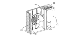
- 1 and 2 are views for explaining the structure and the like of the outdoor unit 10 according to Embodiment 1 of the present invention.
- FIG. 1 is a perspective view of the outdoor unit 10 as viewed from the outlet side.
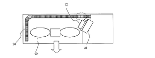
- FIG. 2 is a figure for demonstrating the structure in the outdoor unit 10 from the upper surface side.
- the main body 11 of the outdoor unit 10 includes a housing having two side surfaces 11a and 11c, a front surface 11b, a back surface 11d, an upper surface 11e, and a bottom surface 11f.
- the side surface 11a and the back surface 11d have an opening for sucking air from the outside.
- the front surface 11b has an opening part which becomes a blower outlet which blows air outside.
- the blower outlet is covered with a fan grill to prevent contact between an object or the like and the blower 40 and to ensure safety.
- the main body 11 has at least a heat exchanger 20, an electrical component room 30, a cooling member 32, and a blower 40.
- the blower 40 has, for example, a propeller fan in which a plurality of blades are formed around the propeller labs, and a fan motor on the back side of the propeller fan is driven to rotate so that outdoor air (outside air) is transferred to the heat exchanger 20 Generate a flow to pass through.
- the interior of the main body 1 is divided by a partition plate 12 into a blower chamber 13 in which a blower 40 is installed and a machine chamber 14 in which a compressor, an electrical product 31 and the like are installed.
- FIG. 3 and 4 are diagrams showing the arrangement of the electrical component room 30 and the like according to Embodiment 1 of the present invention.
- the machine room 14 further has an electrical component room 30, and the electrical component room 30 accommodates an electrical component 31.
- the electrical product 31 is an electrical circuit or the like that performs control for driving a device (actuator) such as a compressor in the outdoor unit 10.
- the cooling member 32 is a member such as a comb-shaped heat sink that takes heat (absorbs heat) generated by the electrical product 31 in the electrical product room 30 and dissipates heat.
- the cooling member 32 in this Embodiment is arrange
- the heat exchanger 20 is a heat exchanger that is formed in an L shape by bending and corresponds to the flow of air in two directions from the side surface 11a and the back surface 11d side.
- the heat exchanger 20 when applied to an air conditioner, the heat exchanger 20 functions as a condenser that condenses the refrigerant during the cooling operation, and functions as an evaporator that evaporates the refrigerant during the heating operation.
- the heat exchanger 20 of this Embodiment is comprised with the heat-transfer fin 21 and the heat-transfer tube 22 so that it may mention later, and performs heat exchange with a refrigerant
- the heat transfer fins 21 and the heat transfer tubes 22 use aluminum or an aluminum alloy as a material.
- the heat transfer fins 21 in the present embodiment are constituted by flat (rectangular) fins.
- the heat transfer tube 22 is a flat tube which is a flat heat transfer tube having a curved cross-section.
- the heat transfer fins 21 provide resistance to the air passing through the heat exchanger 20. For this reason, when supplying air in order to promote the heat radiation of the cooling member 32, the heat transfer fin 21 becomes an obstacle. Therefore, as shown in FIG. 4, in the heat exchanger 20 of the present embodiment, the interval between the heat transfer fins 21 is widened in a part of the heat exchanger 20 (a part close to the cooling member 32), and the cooling member 32 Ensure ventilation. By keeping the portion where the interval is widened in part, the cooling efficiency of the cooling member 32 can be increased without significantly reducing the area of the heat transfer fins 21 in the entire heat exchanger 20.
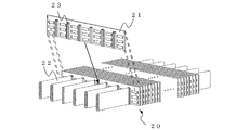
- FIG. 5 is a diagram showing details of the heat exchanger 20 according to Embodiment 1 of the present invention.
- the heat exchanger 20 in the present embodiment fixes, for example, a plurality of heat transfer tubes 22 parallel to each other at a predetermined interval in a dedicated device.
- the direction in which the heat transfer tube 22 is placed is a direction orthogonal to the flow direction of the refrigerant flowing in the tube.
- the heat transfer fins 21 have a plurality of insertion holes 23 in the longitudinal direction (direction in which the heat transfer tubes 22 are arranged).
- the insertion hole 23 is formed by opening a part of the end on the long side of the heat transfer fin 21 so that the heat transfer tube 22 can be inserted into the heat transfer fin 21 (see FIG.
- the heat fin 21 has a comb shape).
- the insertion holes 23 are provided in the same number and the same interval (excluding both ends) as the heat transfer tubes 22.
- the plurality of heat transfer fins 21 are inserted into the fixed plurality of heat transfer tubes 22 so as to be arranged in parallel in the refrigerant flow direction (direction perpendicular to the direction in which the heat transfer tubes 22 are arranged).
- a slit formed by cutting and raising a part of the heat transfer fin 21 may be provided between the insertion holes 23.
- a fin collar raised in a direction perpendicular to the heat transfer fins 21 may be provided at the edge of each insertion hole 23.
- the contact portions (brazing portions) between the heat transfer fins 21 and the heat transfer tubes 22 are joined and fixed by brazing, and the heat exchanger 20 is manufactured.
- the heat transfer fins 21 can be inserted into the heat transfer tubes 22 at an arbitrary interval. For this reason, the structure which changed the space
- the cooling member 32 for cooling the electrical product 31 is provided in the ventilation path in the blower chamber 13 generated by driving the blower 40. 31 can be efficiently cooled. For this reason, reliability can be improved. And since it comprised with the heat exchanger 20 which can be manufactured by inserting and fixing the heat-transfer fin 21 to the heat-transfer tube 22, it becomes a flow path of the air which hits the cooling member 32 in manufacture. It is possible to easily insert the heat transfer fins 21 with a wide interval. For this reason, the improvement of the cooling efficiency of the electrical product 31 and the maintenance of the efficiency of the heat exchanger 20 can be realized at a relatively low cost.
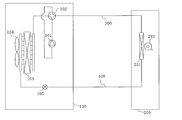
- FIG. FIG. 6 is a diagram showing the configuration of the air-conditioning apparatus according to Embodiment 2 of the present invention.
- a refrigeration cycle apparatus using the outdoor unit 10 described above as an outdoor unit 100 will be described.
- the air conditioner will be described as a representative example of a refrigeration cycle apparatus.
- the air conditioner of FIG. 6 includes an outdoor unit 100 and an indoor unit 200, which are connected by a refrigerant pipe, constitute a refrigerant circuit, and circulate the refrigerant.
- a pipe through which a gaseous refrigerant (gas refrigerant) flows is referred to as a gas pipe 300
- a pipe through which a liquid refrigerant (liquid refrigerant, which may be a gas-liquid two-phase refrigerant) flows is referred to as a liquid pipe 400.
- the outdoor unit 100 includes a compressor 101, a four-way valve 102, an outdoor heat exchanger 103, an outdoor blower 104, and a throttle device (expansion valve) 105.
- Compressor 101 compresses and discharges the sucked refrigerant.
- the operating frequency of the compressor 101 can be arbitrarily changed, and the capacity of the compressor 101 (the amount of refrigerant sent out per unit time) can be finely changed.
- the four-way valve 102 switches the refrigerant flow between the cooling operation and the heating operation based on an instruction from a control device (not shown).
- the outdoor heat exchanger 103 configured by the heat exchanger 20 described above performs heat exchange between the refrigerant and air (outdoor air). For example, during the heating operation, it functions as an evaporator, performs heat exchange between the low-pressure refrigerant flowing from the liquid pipe 400 and the air, and evaporates and vaporizes the refrigerant. Further, during the cooling operation, it functions as a condenser and performs heat exchange between the refrigerant compressed in the compressor 101 that flows in from the four-way valve 102 side and air, thereby condensing and liquefying the refrigerant.
- the outdoor blower 104 that is the blower 40 described above is provided.
- the rotational speed may be finely changed by arbitrarily changing the operating frequency of the fan motor by the inverter device which is the electrical product 31.
- the expansion device 105 is provided to adjust the refrigerant pressure or the like by changing the opening degree.
- the indoor unit 200 includes a load side heat exchanger 201 and a load side blower 202.
- the load side heat exchanger 201 performs heat exchange between the refrigerant and air.
- it functions as a condenser during heating operation, performs heat exchange between the refrigerant flowing in from the gas pipe 300 and air, condenses and liquefies the refrigerant (or gas-liquid two-phase), and moves to the liquid pipe 400 side. Spill.
- the indoor unit 200 is provided with a load-side blower 202 for adjusting the flow of air for heat exchange.
- the operating speed of the load-side blower 202 is determined by, for example, user settings.
- HCFC R22
- HFC R116, R125, R134a, R14, R143a, R152a, R227ea, R23, R236ea, R236fa, R245ca, R245fa, R32, R41, RC318, etc.
- the effect can be achieved for any refrigerating machine oil, regardless of whether or not the refrigerant and oil are dissolved, such as mineral oil, alkylbenzene oil, ester oil, ether oil, and fluorine oil.
- the heat exchanger 20 described in the first embodiment is used as the outdoor heat exchanger 103. Therefore, the electrical product 31 can be efficiently cooled. Thus, the reliability of the apparatus can be improved.
- the present invention can be widely used for outdoor units constituting a refrigeration cycle apparatus, for example, outdoor units such as an air conditioner and a water heater, and various other devices and facilities.
Landscapes
- Engineering & Computer Science (AREA)
- Microelectronics & Electronic Packaging (AREA)
- Physics & Mathematics (AREA)
- Thermal Sciences (AREA)
- Chemical & Material Sciences (AREA)
- Combustion & Propulsion (AREA)
- Mechanical Engineering (AREA)
- General Engineering & Computer Science (AREA)
- Other Air-Conditioning Systems (AREA)
- Heat-Exchange Devices With Radiators And Conduit Assemblies (AREA)
Priority Applications (4)
| Application Number | Priority Date | Filing Date | Title |
|---|---|---|---|
| EP14745818.6A EP2952821B1 (en) | 2013-02-01 | 2014-01-21 | Method for manufacturing an outdoor unit |
| US14/651,068 US20150319885A1 (en) | 2013-02-01 | 2014-01-21 | Outdoor unit and refrigeration cycle apparatus |
| MX2015009976A MX2015009976A (es) | 2013-02-01 | 2014-01-21 | Unidad para exteriores y aparato de ciclo de refrigeracion. |
| AU2014211141A AU2014211141B2 (en) | 2013-02-01 | 2014-01-21 | Outdoor unit and refrigeration cycle apparatus |
Applications Claiming Priority (2)
| Application Number | Priority Date | Filing Date | Title |
|---|---|---|---|
| JP2013-018673 | 2013-02-01 | ||
| JP2013018673A JP2014149131A (ja) | 2013-02-01 | 2013-02-01 | 室外機及び冷凍サイクル装置 |
Publications (1)
| Publication Number | Publication Date |
|---|---|
| WO2014119430A1 true WO2014119430A1 (ja) | 2014-08-07 |
Family
ID=51238290
Family Applications (1)
| Application Number | Title | Priority Date | Filing Date |
|---|---|---|---|
| PCT/JP2014/051155 WO2014119430A1 (ja) | 2013-02-01 | 2014-01-21 | 室外機及び冷凍サイクル装置 |
Country Status (7)
Cited By (2)
| Publication number | Priority date | Publication date | Assignee | Title |
|---|---|---|---|---|
| WO2019193754A1 (ja) * | 2018-04-06 | 2019-10-10 | 三菱電機株式会社 | 室外機 |
| CN113339892A (zh) * | 2021-05-24 | 2021-09-03 | 青岛海信日立空调系统有限公司 | 一种散热模组、电器散热组件及空调器 |
Families Citing this family (14)
| Publication number | Priority date | Publication date | Assignee | Title |
|---|---|---|---|---|
| JP2014149131A (ja) * | 2013-02-01 | 2014-08-21 | Mitsubishi Electric Corp | 室外機及び冷凍サイクル装置 |
| CN106796040A (zh) * | 2014-09-01 | 2017-05-31 | Smac技术有限责任公司 | 直接膨胀式空气调节系统 |
| CN105444293A (zh) * | 2014-09-17 | 2016-03-30 | 珠海格力电器股份有限公司 | 空调器 |
| CN105115066B (zh) * | 2015-09-07 | 2018-03-30 | 海信(广东)空调有限公司 | 一种变频空调室外机 |
| US9848515B1 (en) * | 2016-05-27 | 2017-12-19 | Advanced Micro Devices, Inc. | Multi-compartment computing device with shared cooling device |
| CN106016764B (zh) * | 2016-07-22 | 2022-01-04 | 珠海格力电器股份有限公司 | 一种电器盒的温度调节装置、电器盒及空气能热水器 |
| CN109716034B (zh) * | 2016-09-27 | 2021-03-19 | 三菱电机株式会社 | 空调机的室外机及空调机 |
| WO2018229829A1 (ja) * | 2017-06-12 | 2018-12-20 | 三菱電機株式会社 | 室外機 |
| WO2019150577A1 (ja) * | 2018-02-05 | 2019-08-08 | 三菱電機株式会社 | 室外機及び空気調和機 |
| WO2020075266A1 (ja) * | 2018-10-11 | 2020-04-16 | 三菱電機株式会社 | 室外機 |
| ES2874927T3 (es) * | 2019-04-09 | 2021-11-05 | Pfannenberg Gmbh | Sistema de refrigeración y procedimiento para refrigerar un armario para electrónica |
| CN109974137B (zh) * | 2019-04-19 | 2024-05-17 | 青岛海尔智能技术研发有限公司 | 一种空调室外机和空调器 |
| CN114585871A (zh) * | 2019-10-10 | 2022-06-03 | 三菱电机株式会社 | 热交换器、热交换器单元、冷冻循环装置及热交换部件的制造方法 |
| CN112880052B (zh) * | 2021-03-25 | 2024-10-18 | 珠海格力电器股份有限公司 | 空调室外机及空调 |
Citations (4)
| Publication number | Priority date | Publication date | Assignee | Title |
|---|---|---|---|---|
| JP2005331141A (ja) | 2004-05-19 | 2005-12-02 | Mitsubishi Electric Corp | 冷却システム、空調機、冷凍空調装置、冷却方法 |
| JP2006336935A (ja) * | 2005-06-01 | 2006-12-14 | Mitsubishi Electric Corp | 冷凍空調機の室外ユニット |
| JP2010286187A (ja) * | 2009-06-12 | 2010-12-24 | Mitsubishi Electric Corp | 扁平管熱交換器 |
| WO2013098872A1 (ja) * | 2011-12-26 | 2013-07-04 | 三菱電機株式会社 | 室外機及び空気調和機 |
Family Cites Families (28)
| Publication number | Priority date | Publication date | Assignee | Title |
|---|---|---|---|---|
| US2532303A (en) * | 1945-11-29 | 1950-12-05 | Mccord Corp | Apparatus for making finned tube heat exchangers |
| JP4105320B2 (ja) * | 1999-02-17 | 2008-06-25 | 昭和電工株式会社 | 熱交換器 |
| WO2002053976A1 (en) * | 2000-12-28 | 2002-07-11 | Carrier Corporation | Air conditioner outdoor unit having a control box |
| DE102004057526B4 (de) * | 2003-12-03 | 2020-08-20 | Denso Corporation | Stapelkühler |
| CN100458344C (zh) * | 2005-12-13 | 2009-02-04 | 金龙精密铜管集团股份有限公司 | 一种电制冷满液式机组用铜冷凝换热管 |
| KR101224516B1 (ko) * | 2006-05-17 | 2013-01-22 | 한라공조주식회사 | 축냉부를 구비한 증발기 |
| JP4929866B2 (ja) * | 2006-06-16 | 2012-05-09 | 株式会社ノーリツ | 熱交換器およびこれを備えた温水装置 |
| US7686072B2 (en) * | 2007-02-05 | 2010-03-30 | Riello S.P.A. | Heat exchanger and methods of producing the same |
| JP2008267686A (ja) * | 2007-04-19 | 2008-11-06 | Denso Corp | 冷媒蒸発器 |
| JP4923107B2 (ja) * | 2007-09-28 | 2012-04-25 | 東芝キヤリア株式会社 | 空気調和機の室外機 |
| JP2009138909A (ja) * | 2007-12-10 | 2009-06-25 | Denso Corp | 配管継手装置 |
| JP2009281693A (ja) * | 2008-05-26 | 2009-12-03 | Mitsubishi Electric Corp | 熱交換器、その製造方法及びこの熱交換器を用いた空調冷凍装置 |
| JP2010019534A (ja) * | 2008-07-14 | 2010-01-28 | Daikin Ind Ltd | 熱交換器 |
| JP4892713B2 (ja) * | 2008-08-25 | 2012-03-07 | シャープ株式会社 | 空気調和機 |
| JP5408951B2 (ja) * | 2008-10-16 | 2014-02-05 | 三菱重工業株式会社 | 冷媒蒸発器およびそれを用いた空調装置 |
| KR20110026193A (ko) * | 2009-09-07 | 2011-03-15 | 삼성전자주식회사 | 발열체 냉각 시스템 및 배터리 냉각 시스템 |
| JP5140051B2 (ja) * | 2009-09-17 | 2013-02-06 | 三菱電機株式会社 | 熱交換器および熱交換器用フィンとその製造方法 |
| JP5390417B2 (ja) * | 2010-01-15 | 2014-01-15 | 三菱電機株式会社 | 熱交換器およびその製造方法 |
| JP2011196558A (ja) * | 2010-03-17 | 2011-10-06 | Panasonic Corp | 電装品箱 |
| JP2012002415A (ja) * | 2010-06-16 | 2012-01-05 | Panasonic Corp | 空気調和機の室外機 |
| JP5787619B2 (ja) * | 2010-06-30 | 2015-09-30 | 三菱電機株式会社 | 熱交換器の製造装置 |
| CN201888043U (zh) * | 2010-12-10 | 2011-06-29 | 珠海格力电器股份有限公司 | 电器盒及包含该电器盒的空调器 |
| WO2012098920A1 (ja) * | 2011-01-21 | 2012-07-26 | ダイキン工業株式会社 | 熱交換器および空気調和機 |
| WO2012098921A1 (ja) * | 2011-01-21 | 2012-07-26 | ダイキン工業株式会社 | 熱交換器および空気調和機 |
| JP2012225634A (ja) * | 2011-04-04 | 2012-11-15 | Denso Corp | 熱交換器 |
| JP5796564B2 (ja) * | 2011-11-30 | 2015-10-21 | 株式会社デンソー | 熱交換器 |
| JP5464207B2 (ja) * | 2011-12-28 | 2014-04-09 | ダイキン工業株式会社 | 冷凍装置の室外ユニット |
| JP2014149131A (ja) * | 2013-02-01 | 2014-08-21 | Mitsubishi Electric Corp | 室外機及び冷凍サイクル装置 |
-
2013
- 2013-02-01 JP JP2013018673A patent/JP2014149131A/ja active Pending
-
2014
- 2014-01-21 EP EP14745818.6A patent/EP2952821B1/en active Active
- 2014-01-21 AU AU2014211141A patent/AU2014211141B2/en not_active Ceased
- 2014-01-21 MX MX2015009976A patent/MX2015009976A/es unknown
- 2014-01-21 US US14/651,068 patent/US20150319885A1/en not_active Abandoned
- 2014-01-21 WO PCT/JP2014/051155 patent/WO2014119430A1/ja active Application Filing
- 2014-01-29 CN CN201420056402.9U patent/CN203757884U/zh not_active Expired - Fee Related
- 2014-01-29 CN CN201410042935.6A patent/CN103968469A/zh active Pending
Patent Citations (4)
| Publication number | Priority date | Publication date | Assignee | Title |
|---|---|---|---|---|
| JP2005331141A (ja) | 2004-05-19 | 2005-12-02 | Mitsubishi Electric Corp | 冷却システム、空調機、冷凍空調装置、冷却方法 |
| JP2006336935A (ja) * | 2005-06-01 | 2006-12-14 | Mitsubishi Electric Corp | 冷凍空調機の室外ユニット |
| JP2010286187A (ja) * | 2009-06-12 | 2010-12-24 | Mitsubishi Electric Corp | 扁平管熱交換器 |
| WO2013098872A1 (ja) * | 2011-12-26 | 2013-07-04 | 三菱電機株式会社 | 室外機及び空気調和機 |
Non-Patent Citations (1)
| Title |
|---|
| See also references of EP2952821A4 |
Cited By (2)
| Publication number | Priority date | Publication date | Assignee | Title |
|---|---|---|---|---|
| WO2019193754A1 (ja) * | 2018-04-06 | 2019-10-10 | 三菱電機株式会社 | 室外機 |
| CN113339892A (zh) * | 2021-05-24 | 2021-09-03 | 青岛海信日立空调系统有限公司 | 一种散热模组、电器散热组件及空调器 |
Also Published As
| Publication number | Publication date |
|---|---|
| MX2015009976A (es) | 2015-09-29 |
| EP2952821A1 (en) | 2015-12-09 |
| AU2014211141B2 (en) | 2016-08-11 |
| EP2952821B1 (en) | 2019-07-10 |
| AU2014211141A1 (en) | 2015-07-02 |
| US20150319885A1 (en) | 2015-11-05 |
| JP2014149131A (ja) | 2014-08-21 |
| CN103968469A (zh) | 2014-08-06 |
| CN203757884U (zh) | 2014-08-06 |
| EP2952821A4 (en) | 2016-08-24 |
Similar Documents
| Publication | Publication Date | Title |
|---|---|---|
| WO2014119430A1 (ja) | 室外機及び冷凍サイクル装置 | |
| US20170268790A1 (en) | Air-conditioning device | |
| US20220214085A1 (en) | Evaporator and refrigeration cycle apparatus including the same | |
| JP5447569B2 (ja) | 空気調和装置の熱交換器及び空気調和装置 | |
| KR20090096600A (ko) | 다른 멀티채널 튜브를 갖는 멀티채널 열 교환기 | |
| JP6888102B2 (ja) | 熱交換器ユニットおよび冷凍サイクル装置 | |
| WO2018138770A1 (ja) | 熱源側ユニット、及び、冷凍サイクル装置 | |
| WO2016059696A1 (ja) | 冷凍サイクル装置 | |
| WO2016009565A1 (ja) | 冷凍サイクル装置 | |
| US10480869B2 (en) | Heat exchanger and refrigeration cycle apparatus including the same | |
| WO2015140878A1 (ja) | アキュムレータ及び冷凍サイクル装置 | |
| WO2020246337A1 (ja) | 熱交換器、冷凍サイクル装置 | |
| WO2016038659A1 (ja) | 冷凍サイクル装置 | |
| JP6298992B2 (ja) | 空気調和機 | |
| WO2022102077A1 (ja) | 冷凍サイクル装置 | |
| WO2016016999A1 (ja) | 冷凍サイクル装置 | |
| WO2017056214A1 (ja) | 空気調和装置 | |
| WO2015140877A1 (ja) | 絞り装置及び冷凍サイクル装置 | |
| JP7357137B1 (ja) | 空気調和機 | |
| WO2021117156A1 (ja) | 空気調和機の室内機 | |
| WO2025009312A1 (ja) | 冷凍装置 | |
| JP2008256312A (ja) | 空気調和装置 | |
| WO2015189948A1 (ja) | 冷凍サイクル装置 |
Legal Events
| Date | Code | Title | Description |
|---|---|---|---|
| 121 | Ep: the epo has been informed by wipo that ep was designated in this application |
Ref document number: 14745818 Country of ref document: EP Kind code of ref document: A1 |
|
| WWE | Wipo information: entry into national phase |
Ref document number: 14651068 Country of ref document: US |
|
| ENP | Entry into the national phase |
Ref document number: 2014211141 Country of ref document: AU Date of ref document: 20140121 Kind code of ref document: A |
|
| WWE | Wipo information: entry into national phase |
Ref document number: 2014745818 Country of ref document: EP |
|
| WWE | Wipo information: entry into national phase |
Ref document number: MX/A/2015/009976 Country of ref document: MX |
|
| NENP | Non-entry into the national phase |
Ref country code: DE |