EP2952821B1 - Method for manufacturing an outdoor unit - Google Patents
Method for manufacturing an outdoor unit Download PDFInfo
- Publication number
- EP2952821B1 EP2952821B1 EP14745818.6A EP14745818A EP2952821B1 EP 2952821 B1 EP2952821 B1 EP 2952821B1 EP 14745818 A EP14745818 A EP 14745818A EP 2952821 B1 EP2952821 B1 EP 2952821B1
- Authority
- EP
- European Patent Office
- Prior art keywords
- heat transmission
- heat
- air
- fins
- heat exchanger
- Prior art date
- Legal status (The legal status is an assumption and is not a legal conclusion. Google has not performed a legal analysis and makes no representation as to the accuracy of the status listed.)
- Active
Links
- 238000004519 manufacturing process Methods 0.000 title claims description 7
- 238000000034 method Methods 0.000 title claims description 5
- 230000005540 biological transmission Effects 0.000 claims description 71
- 239000003507 refrigerant Substances 0.000 claims description 47
- 238000001816 cooling Methods 0.000 claims description 38
- 238000004378 air conditioning Methods 0.000 claims description 11
- 238000003780 insertion Methods 0.000 claims description 10
- 230000037431 insertion Effects 0.000 claims description 10
- 238000005219 brazing Methods 0.000 claims description 3
- 238000005304 joining Methods 0.000 claims 1
- 239000007788 liquid Substances 0.000 description 7
- 239000010721 machine oil Substances 0.000 description 6
- 238000005057 refrigeration Methods 0.000 description 5
- 238000010438 heat treatment Methods 0.000 description 4
- 239000000203 mixture Substances 0.000 description 4
- 239000003921 oil Substances 0.000 description 4
- 230000000694 effects Effects 0.000 description 3
- QGZKDVFQNNGYKY-UHFFFAOYSA-N Ammonia Chemical compound N QGZKDVFQNNGYKY-UHFFFAOYSA-N 0.000 description 2
- CURLTUGMZLYLDI-UHFFFAOYSA-N Carbon dioxide Chemical compound O=C=O CURLTUGMZLYLDI-UHFFFAOYSA-N 0.000 description 2
- RTZKZFJDLAIYFH-UHFFFAOYSA-N Diethyl ether Chemical compound CCOCC RTZKZFJDLAIYFH-UHFFFAOYSA-N 0.000 description 2
- ATUOYWHBWRKTHZ-UHFFFAOYSA-N Propane Chemical compound CCC ATUOYWHBWRKTHZ-UHFFFAOYSA-N 0.000 description 2
- XAGFODPZIPBFFR-UHFFFAOYSA-N aluminium Chemical compound [Al] XAGFODPZIPBFFR-UHFFFAOYSA-N 0.000 description 2
- 229910052782 aluminium Inorganic materials 0.000 description 2
- NNPPMTNAJDCUHE-UHFFFAOYSA-N isobutane Chemical compound CC(C)C NNPPMTNAJDCUHE-UHFFFAOYSA-N 0.000 description 2
- 238000005192 partition Methods 0.000 description 2
- FYIRUPZTYPILDH-UHFFFAOYSA-N 1,1,1,2,3,3-hexafluoropropane Chemical compound FC(F)C(F)C(F)(F)F FYIRUPZTYPILDH-UHFFFAOYSA-N 0.000 description 1
- 229910000838 Al alloy Inorganic materials 0.000 description 1
- OTMSDBZUPAUEDD-UHFFFAOYSA-N Ethane Chemical compound CC OTMSDBZUPAUEDD-UHFFFAOYSA-N 0.000 description 1
- YCKRFDGAMUMZLT-UHFFFAOYSA-N Fluorine atom Chemical compound [F] YCKRFDGAMUMZLT-UHFFFAOYSA-N 0.000 description 1
- -1 HFO1234yf Substances 0.000 description 1
- 150000004996 alkyl benzenes Chemical class 0.000 description 1
- 229910021529 ammonia Inorganic materials 0.000 description 1
- 238000005452 bending Methods 0.000 description 1
- 239000001273 butane Substances 0.000 description 1
- 229910002092 carbon dioxide Inorganic materials 0.000 description 1
- 239000001569 carbon dioxide Substances 0.000 description 1
- 238000005520 cutting process Methods 0.000 description 1
- 230000001419 dependent effect Effects 0.000 description 1
- 230000002708 enhancing effect Effects 0.000 description 1
- 239000010696 ester oil Substances 0.000 description 1
- 238000001704 evaporation Methods 0.000 description 1
- 239000011737 fluorine Substances 0.000 description 1
- 229910052731 fluorine Inorganic materials 0.000 description 1
- 230000017525 heat dissipation Effects 0.000 description 1
- 239000001282 iso-butane Substances 0.000 description 1
- 238000012423 maintenance Methods 0.000 description 1
- 239000002480 mineral oil Substances 0.000 description 1
- 235000010446 mineral oil Nutrition 0.000 description 1
- IJDNQMDRQITEOD-UHFFFAOYSA-N n-butane Chemical compound CCCC IJDNQMDRQITEOD-UHFFFAOYSA-N 0.000 description 1
- OFBQJSOFQDEBGM-UHFFFAOYSA-N n-pentane Natural products CCCCC OFBQJSOFQDEBGM-UHFFFAOYSA-N 0.000 description 1
- MSSNHSVIGIHOJA-UHFFFAOYSA-N pentafluoropropane Chemical compound FC(F)CC(F)(F)F MSSNHSVIGIHOJA-UHFFFAOYSA-N 0.000 description 1
- 239000001294 propane Substances 0.000 description 1
- QQONPFPTGQHPMA-UHFFFAOYSA-N propylene Natural products CC=C QQONPFPTGQHPMA-UHFFFAOYSA-N 0.000 description 1
- 125000004805 propylene group Chemical group [H]C([H])([H])C([H])([*:1])C([H])([H])[*:2] 0.000 description 1
- 239000000126 substance Substances 0.000 description 1
- XLYOFNOQVPJJNP-UHFFFAOYSA-N water Substances O XLYOFNOQVPJJNP-UHFFFAOYSA-N 0.000 description 1
Images

Classifications
-
- H—ELECTRICITY
- H05—ELECTRIC TECHNIQUES NOT OTHERWISE PROVIDED FOR
- H05K—PRINTED CIRCUITS; CASINGS OR CONSTRUCTIONAL DETAILS OF ELECTRIC APPARATUS; MANUFACTURE OF ASSEMBLAGES OF ELECTRICAL COMPONENTS
- H05K7/00—Constructional details common to different types of electric apparatus
- H05K7/20—Modifications to facilitate cooling, ventilating, or heating
- H05K7/2029—Modifications to facilitate cooling, ventilating, or heating using a liquid coolant with phase change in electronic enclosures
- H05K7/20354—Refrigerating circuit comprising a compressor
-
- F—MECHANICAL ENGINEERING; LIGHTING; HEATING; WEAPONS; BLASTING
- F24—HEATING; RANGES; VENTILATING
- F24F—AIR-CONDITIONING; AIR-HUMIDIFICATION; VENTILATION; USE OF AIR CURRENTS FOR SCREENING
- F24F1/00—Room units for air-conditioning, e.g. separate or self-contained units or units receiving primary air from a central station
- F24F1/06—Separate outdoor units, e.g. outdoor unit to be linked to a separate room comprising a compressor and a heat exchanger
- F24F1/14—Heat exchangers specially adapted for separate outdoor units
- F24F1/18—Heat exchangers specially adapted for separate outdoor units characterised by their shape
-
- F—MECHANICAL ENGINEERING; LIGHTING; HEATING; WEAPONS; BLASTING
- F24—HEATING; RANGES; VENTILATING
- F24F—AIR-CONDITIONING; AIR-HUMIDIFICATION; VENTILATION; USE OF AIR CURRENTS FOR SCREENING
- F24F1/00—Room units for air-conditioning, e.g. separate or self-contained units or units receiving primary air from a central station
- F24F1/06—Separate outdoor units, e.g. outdoor unit to be linked to a separate room comprising a compressor and a heat exchanger
- F24F1/20—Electric components for separate outdoor units
- F24F1/24—Cooling of electric components
-
- H—ELECTRICITY
- H05—ELECTRIC TECHNIQUES NOT OTHERWISE PROVIDED FOR
- H05K—PRINTED CIRCUITS; CASINGS OR CONSTRUCTIONAL DETAILS OF ELECTRIC APPARATUS; MANUFACTURE OF ASSEMBLAGES OF ELECTRICAL COMPONENTS
- H05K7/00—Constructional details common to different types of electric apparatus
- H05K7/20—Modifications to facilitate cooling, ventilating, or heating
- H05K7/2089—Modifications to facilitate cooling, ventilating, or heating for power electronics, e.g. for inverters for controlling motor
- H05K7/20909—Forced ventilation, e.g. on heat dissipaters coupled to components
- H05K7/20918—Forced ventilation, e.g. on heat dissipaters coupled to components the components being isolated from air flow, e.g. hollow heat sinks, wind tunnels or funnels
-
- H—ELECTRICITY
- H05—ELECTRIC TECHNIQUES NOT OTHERWISE PROVIDED FOR
- H05K—PRINTED CIRCUITS; CASINGS OR CONSTRUCTIONAL DETAILS OF ELECTRIC APPARATUS; MANUFACTURE OF ASSEMBLAGES OF ELECTRICAL COMPONENTS
- H05K7/00—Constructional details common to different types of electric apparatus
- H05K7/20—Modifications to facilitate cooling, ventilating, or heating
- H05K7/2089—Modifications to facilitate cooling, ventilating, or heating for power electronics, e.g. for inverters for controlling motor
- H05K7/20936—Liquid coolant with phase change
-
- H—ELECTRICITY
- H05—ELECTRIC TECHNIQUES NOT OTHERWISE PROVIDED FOR
- H05K—PRINTED CIRCUITS; CASINGS OR CONSTRUCTIONAL DETAILS OF ELECTRIC APPARATUS; MANUFACTURE OF ASSEMBLAGES OF ELECTRICAL COMPONENTS
- H05K7/00—Constructional details common to different types of electric apparatus
- H05K7/20—Modifications to facilitate cooling, ventilating, or heating
- H05K7/2029—Modifications to facilitate cooling, ventilating, or heating using a liquid coolant with phase change in electronic enclosures
- H05K7/20318—Condensers
Definitions
- the present invention relates to an outdoor unit for an air-conditioning apparatus using a fin-and-tube heat exchanger.
- the present invention relates to a cooling structure of an electric component installed in an outdoor unit.
- An outdoor unit for an air-conditioning apparatus includes various electric components (electric parts) such as an inverter circuit for variably controlling the rotation speed of, for example, a compressor or a fan.
- electric components such as an inverter circuit for variably controlling the rotation speed of, for example, a compressor or a fan.
- Some electric components generate heat because of a flow of large current, for example. A high temperature may cause damage to the electric components, unstable driving, and other problems, which lead to reduced reliability of the outdoor unit. To prevent this, such electric components are cooled in order to prevent the electric components from reaching high temperatures.
- a cooling member is placed in an air passage of a heat exchanger and removes heat from the electric components so that the electric components are cooled (see, for example, Patent Literature 1).
- the heat exchanger is configured such that the distance between heat transmission fins of the heat exchanger in a position where the heat exchanger is located close to the cooling member is larger than other positions therein.
- Patent Literature 1 Japanese Unexamined Patent Application Publication No. 2005-331141
- JP 2005 331141A discloses that a heat radiating side 87 of the heat pipe 8 is positioned in an air trunk formed by a cooling fan 4. Further a heat radiating fin 7 is mounted at the heat radiating side 87 of the heat pipe 8, and a clearance of the cooling fans of a heat exchanger 5 in a range corresponding to the heat radiating fin 7 is wider than that of the other range.
- JP 2000 234883A discloses inserting the pipes to the fins aligned with predetermined distance in between, and then, fixing the pipes and the fins by brazing.
- An outdoor unit includes: a heat exchanger including heat transmission fins and heat transmission pipes, the heat transmission fins being spaced from one another with a distance, fitted to and fixed to the heat transmission pipes, so that heat is exchanged between refrigerant passing through the heat transmission pipes and air passing between the heat transmission fins; an electric component including a part of an electric system that controls equipment; and a cooling member disposed in a channel of air passing through the heat exchanger, the cooling member configured to dissipate heat from the electric component to the air, wherein the heat transmission fins are fitted to the heat transmission pipes such that the distance between the heat transmission fins is configured to be larger, in a position corresponding to a position where the cooling member is located and that serves as a passage of the air passing through the cooling member, than in other positions in the heat exchanger.
- the cooling member is disposed in the channel of air passing through the heat exchanger so as to cool an electric component.
- the electric component can be efficiently cooled.
- the heat transmission fins are fitted to the heat transmission pipes with increased distances therebetween in a position corresponding to the location of the cooling member.
- Embodiment 1 of the present invention will be described hereinafter.
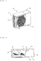
- Figs. 1 and 2 illustrate a configuration of an outdoor unit 10 according to Embodiment 1 of the present invention, for example.
- Fig. 1 is a perspective view of the outdoor unit 10 when viewed from an air outlet.
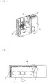
- Fig. 2 is an illustration for describing the internal configuration of the outdoor unit 10 when viewed from above.
- the outdoor unit 10 has a body 11 including a casing having two side surfaces 11a and 11c, a front surface 11b, a rear surface 11d, an upper surface 11 e, and a bottom surface 11f.
- the side surface 11a and the rear surface 11d have openings through which air is taken in from the outside.
- the front surface 11b has an opening serving as an air outlet through which air blows out to the outside.
- the air outlet is covered with a fan grille in order to prevent contact between an object or the like and a blower device 40 for safety.
- the body 11 includes at least a heat exchanger 20, an electric component chamber 30, a cooling member 32, and a blower device 40.
- the blower device 40 includes, for example, a propeller fan in which a plurality of vanes are disposed around a propeller boss.
- a fan motor disposed near the rear surface of the propeller fan is driven to rotate and creates an air flow in which air in the outside (outdoor air) passes through the heat exchanger 20.
- the inside of the body 1 is partitioned by a partition plate 12 into a blower device chamber 13 in which the blower device 40 is disposed and a machinery chamber 14 in which the compressor and an electric component 31, for example, are disposed.
- Figs. 3 and 4 illustrate an arrangement of the electric component chamber 30 and other components in Embodiment 1 of the present invention.
- the machinery chamber 14 further includes an electric component chamber 30, and the electric component chamber 30 accommodates the electric component 31.
- the electric component 31 is, for example, an electric circuit that performs control for, for example, driving equipment (an actuator) such as the compressor in the outdoor unit 10.
- the cooling member 32 is a member such as a comb-shaped heat sink that takes away (receives) heat generated by the electric component 31 in the electric component chamber 30 and rejects heat.
- the cooling member 32 of Embodiment 1 is disposed at a location in an air passage through which air is caused to pass by driving the blower device 40.
- the heat exchanger 20 is formed in an L shape by bending and is designed such that air flows in two directions from the side surface 11a and the rear surface 11d, respectively.
- the heat exchanger 20 serves as a condenser for condensing refrigerant in a cooling operation and serves as an evaporator for evaporating refrigerant in a heating operation.
- the heat exchanger 20 of Embodiment 1 includes heat transmission fins 21 and heat transmission pipes 22 and exchanges heat between the refrigerant and air outside the room (outdoor air).
- Each of the heat transmission fins 21 and the heat transmission pipes 22 is made of aluminum or an aluminum alloy.
- the use of, for example, aluminum can enhance the heat exchange efficiency and reduce the weight and size of the heat exchanger.
- the heat transmission fins 21 of Embodiment 1 are flat-plate (rectangular) fins.
- the heat transmission pipes 22 are flat tubes that are flat-shaped heat transmission pipes partially curved in cross section.
- the heat transmission fins 21 serve as a resistance to air passing through the heat exchanger 20.
- the heat transmission fins 21 are obstacles in supplying air in order to facilitate heat dissipation of the cooling member 32.
- the heat exchanger 20 of Embodiment 1 is configured such that the distance between the heat transmission fins 21 is increased in a position (a position close to the cooling member 32) of the heat exchanger 20 so as to obtain a sufficiently large air passage for the cooling member 32. Since the distance is partially increased, the efficiency of the cooling member 32 can be increased without a significant decrease in the area of the heat transmission fins 21 in the entire heat exchanger 20.
- Fig. 5 illustrates the heat exchanger 20 of Embodiment 1 of the present invention in detail.
- the heat transmission pipes 22 are arranged with predetermined distances and fixed in, for example, a dedicated device.
- the direction in which the heat transmission pipes 22 are arranged side by side is orthogonal to the channel direction of the refrigerant flowing in the pipes.
- the heat transmission fins 21 include a plurality of insertion cutouts 23 arranged in the longitudinal direction (i.e., the direction in which the heat transmission pipes 22 are arranged side by side).
- Each of the insertion cutouts has one open end on one of the longitudinal edges of a corresponding of the heat transmission fins 21, so that the heat transmission pipes 22 can be fitted to the heat transmission fins 21. That is, the heat transmission fins 21 have comb-like shapes.
- the number of the insertion cutouts 23 is equal to that of the heat transmission pipes 22, and the insertion cutouts 23 are arranged with the same distances therebetween as those between the heat transmission pipes 22 (except both ends), for example.
- the heat transmission fins 21 are fitted to and fixed to the heat transmission pipes 22 such that the heat transmission fins 21 are parallel to one another in the refrigerant channel direction (i.e., the direction orthogonal to the direction in which the heat transmission pipes 22 are arranged side by side).
- Slits formed by cutting and raising part of the heat transmission fins 21 may be, but are not limited to being, provided between the insertion cutouts 23.
- Fin collars may be formed so as to stand vertically on the heat transmission fins 21 at the rims of the insertion cutouts 23.
- Portions (brazed portions) in which the heat transmission fins 21 are in contact with the heat transmission pipes 22 are joined by brazing, thereby fabricating the heat exchanger 20.
- This fabrication enables the heat transmission fins 21 to be fitted to the heat transmission pipes 22 with desired distances therebetween.
- the configuration in which the distance between the heat transmission fins 21 varies in the single heat exchanger 20 can be obtained at a relatively low cost.
- the outdoor unit 10 of Embodiment 1 includes the cooling member 32 for cooling the electric component 31 in the air passage of air flow formed when driving the blower device 40 in the blower device chamber 13.
- the electric component 31 can be efficiently cooled.
- reliability can be enhanced.
- the heat exchanger 20 is configured such that the heat transmission fins 21 are fitted to and fixed to the heat transmission pipes 22.
- insertion can be easily performed with wide distances between the heat transmission fins 21 serving as a channel of air that is in contact with the cooling member 32.
- both enhancement of cooling efficiency of the electric component 31 and maintenance of efficiency of the heat exchanger 20 can be achieved at a relatively low cost.
- Fig. 6 illustrates a configuration of an air-conditioning apparatus.
- a refrigeration cycle apparatus using the above-described outdoor unit 10 as an outdoor unit 100 will be described.
- the air-conditioning apparatus will be described as a typical example of a refrigeration cycle apparatus.
- the air-conditioning apparatus illustrated in Fig. 6 includes the outdoor unit 100 and an indoor unit 200 that are connected to each other by refrigerant pipes so that refrigerant circulates therein.
- a pipe in which a gas refrigerant flows will be referred to as a gas pipe 300
- a pipe in which a liquid refrigerant (which may be a two-phase gas-liquid refrigerant) flows will be referred to as a liquid pipe 400.
- the outdoor unit 100 includes a compressor 101, a four-way valve 102, an outdoor-side heat exchanger 103, an outdoor-side blower device 104, and an expansion device (an expansion valve) 105.
- the compressor 101 compresses a sucked refrigerant and discharges the compressed refrigerant.
- the presence of, for example, an inverter as an electric component 31 can change the operating frequency of the compressor 101 as intended so that the capacity (the amount of the refrigerant that is sent from the compressor 101 in a unit time) of the compressor 101 can be minutely changed.
- the four-way valve 102 switches a flow of the refrigerant between a cooling operation and a heating operation.
- the outdoor-side heat exchanger 103 constituted by the heat exchanger 20 described above exchanges heat between refrigerant and air (outdoor air). Specifically, in the heating operation, the outdoor-side heat exchanger 103 serves as an evaporator that exchanges heat between a low-pressure refrigerant from the liquid pipe 400 and air, evaporates the refrigerant, and vaporizes the refrigerant. In the cooling operation, the outdoor-side heat exchanger 103 serves as a condenser that exchanges heat between refrigerant that has flowed from the four-way valve 102 and that has been compressed in the compressor 101 and air, condenses the refrigerant, and liquefies the refrigerant.
- An outdoor-side blower device 104 that is the above-described blower device 40 is provided.
- the outdoor-side blower device 104 may also be configured such that the inverter as the electric component 31 can change the operating frequency of the fan motor as intended so as to minutely change the rotation speed.
- the expansion device 105 changes its opening degree so as to adjust the pressure of the refrigerant, for example.
- the indoor unit 200 includes a load-side heat exchanger 201 and a load-side blower device 202.
- the load-side heat exchanger 201 exchanges heat between refrigerant and air.
- the load-side heat exchanger 201 serves as a condenser that exchanges heat between refrigerant from the gas pipe 300 and air, condenses the refrigerant, liquefies the condensed refrigerant (or changes the refrigerant into a two-phase gas-liquid refrigerant), and causes the refrigerant to flow out toward the liquid pipe 400.
- the load-side heat exchanger 201 serves as an evaporator that exchanges heat between refrigerant that has changed into a low-pressure state by the expansion device 105, for example, and air, causes the refrigerant to receive heat from the air, evaporates and vaporizes the refrigerant, and causes the resulting refrigerant to flow out toward the gas pipe 300.
- the indoor unit 200 also includes a load-side blower device 202 for adjusting the flow of air for use in the heat exchange.
- the operation speed of the load-side blower device 202 can be set by, for example, a user.
- the above-described refrigeration cycle apparatus can use HCFC (R22), HFC (e.g., R116, R125, R134a, R14, R143a, R152a, R227ea, R23, R236ea, R236fa, R245ca, R245fa, R32, R41, RC318, or a refrigerant mixture of some of these refrigerants, such as R407A, R407B, R407C, R407D, R407E, R410A, R410B, R404A, R507A, R508A, or R508B), HC (e.g., butane, isobutane, ethane, propane, propylene, or a refrigerant mixture of some of these refrigerants), a natural refrigerant (e.g., air, carbon dioxide, ammonia, or a refrigerant mixture of some of these refrigerant substances), a low-GWP ref
- refrigerating machine oil such as mineral oil-based refrigerating machine oil, alkylbenzene oil-based refrigerating machine oil, ester oil-based refrigerating machine oil, ether oil-based refrigerating machine oil, or fluorine oil-based refrigerating machine oil.
- the heat exchanger 20 of Embodiment 1 is used as the outdoor-side heat exchanger 103.
- the electric component 31 can be efficiently cooled, thereby enhancing the reliability of the apparatus.
- the present invention is widely applicable to outdoor units constituting refrigeration cycle apparatuses, such as an outdoor unit of an air-conditioning apparatus or a hot water supply, and other apparatuses and equipment.
Landscapes
- Engineering & Computer Science (AREA)
- Microelectronics & Electronic Packaging (AREA)
- Physics & Mathematics (AREA)
- Thermal Sciences (AREA)
- Chemical & Material Sciences (AREA)
- Combustion & Propulsion (AREA)
- Mechanical Engineering (AREA)
- General Engineering & Computer Science (AREA)
- Other Air-Conditioning Systems (AREA)
- Heat-Exchange Devices With Radiators And Conduit Assemblies (AREA)
Applications Claiming Priority (2)
| Application Number | Priority Date | Filing Date | Title |
|---|---|---|---|
| JP2013018673A JP2014149131A (ja) | 2013-02-01 | 2013-02-01 | 室外機及び冷凍サイクル装置 |
| PCT/JP2014/051155 WO2014119430A1 (ja) | 2013-02-01 | 2014-01-21 | 室外機及び冷凍サイクル装置 |
Publications (3)
| Publication Number | Publication Date |
|---|---|
| EP2952821A1 EP2952821A1 (en) | 2015-12-09 |
| EP2952821A4 EP2952821A4 (en) | 2016-08-24 |
| EP2952821B1 true EP2952821B1 (en) | 2019-07-10 |
Family
ID=51238290
Family Applications (1)
| Application Number | Title | Priority Date | Filing Date |
|---|---|---|---|
| EP14745818.6A Active EP2952821B1 (en) | 2013-02-01 | 2014-01-21 | Method for manufacturing an outdoor unit |
Country Status (7)
Families Citing this family (16)
| Publication number | Priority date | Publication date | Assignee | Title |
|---|---|---|---|---|
| JP2014149131A (ja) * | 2013-02-01 | 2014-08-21 | Mitsubishi Electric Corp | 室外機及び冷凍サイクル装置 |
| CN106796040A (zh) * | 2014-09-01 | 2017-05-31 | Smac技术有限责任公司 | 直接膨胀式空气调节系统 |
| CN105444293A (zh) * | 2014-09-17 | 2016-03-30 | 珠海格力电器股份有限公司 | 空调器 |
| CN105115066B (zh) * | 2015-09-07 | 2018-03-30 | 海信(广东)空调有限公司 | 一种变频空调室外机 |
| US9848515B1 (en) * | 2016-05-27 | 2017-12-19 | Advanced Micro Devices, Inc. | Multi-compartment computing device with shared cooling device |
| CN106016764B (zh) * | 2016-07-22 | 2022-01-04 | 珠海格力电器股份有限公司 | 一种电器盒的温度调节装置、电器盒及空气能热水器 |
| CN109716034B (zh) * | 2016-09-27 | 2021-03-19 | 三菱电机株式会社 | 空调机的室外机及空调机 |
| WO2018229829A1 (ja) * | 2017-06-12 | 2018-12-20 | 三菱電機株式会社 | 室外機 |
| WO2019150577A1 (ja) * | 2018-02-05 | 2019-08-08 | 三菱電機株式会社 | 室外機及び空気調和機 |
| WO2019193754A1 (ja) * | 2018-04-06 | 2019-10-10 | 三菱電機株式会社 | 室外機 |
| WO2020075266A1 (ja) * | 2018-10-11 | 2020-04-16 | 三菱電機株式会社 | 室外機 |
| ES2874927T3 (es) * | 2019-04-09 | 2021-11-05 | Pfannenberg Gmbh | Sistema de refrigeración y procedimiento para refrigerar un armario para electrónica |
| CN109974137B (zh) * | 2019-04-19 | 2024-05-17 | 青岛海尔智能技术研发有限公司 | 一种空调室外机和空调器 |
| CN114585871A (zh) * | 2019-10-10 | 2022-06-03 | 三菱电机株式会社 | 热交换器、热交换器单元、冷冻循环装置及热交换部件的制造方法 |
| CN112880052B (zh) * | 2021-03-25 | 2024-10-18 | 珠海格力电器股份有限公司 | 空调室外机及空调 |
| CN113339892B (zh) * | 2021-05-24 | 2022-11-15 | 青岛海信日立空调系统有限公司 | 一种散热模组、电器散热组件及空调器 |
Family Cites Families (32)
| Publication number | Priority date | Publication date | Assignee | Title |
|---|---|---|---|---|
| US2532303A (en) * | 1945-11-29 | 1950-12-05 | Mccord Corp | Apparatus for making finned tube heat exchangers |
| JP4105320B2 (ja) * | 1999-02-17 | 2008-06-25 | 昭和電工株式会社 | 熱交換器 |
| WO2002053976A1 (en) * | 2000-12-28 | 2002-07-11 | Carrier Corporation | Air conditioner outdoor unit having a control box |
| DE102004057526B4 (de) * | 2003-12-03 | 2020-08-20 | Denso Corporation | Stapelkühler |
| JP2005331141A (ja) * | 2004-05-19 | 2005-12-02 | Mitsubishi Electric Corp | 冷却システム、空調機、冷凍空調装置、冷却方法 |
| JP2006336935A (ja) * | 2005-06-01 | 2006-12-14 | Mitsubishi Electric Corp | 冷凍空調機の室外ユニット |
| CN100458344C (zh) * | 2005-12-13 | 2009-02-04 | 金龙精密铜管集团股份有限公司 | 一种电制冷满液式机组用铜冷凝换热管 |
| KR101224516B1 (ko) * | 2006-05-17 | 2013-01-22 | 한라공조주식회사 | 축냉부를 구비한 증발기 |
| JP4929866B2 (ja) * | 2006-06-16 | 2012-05-09 | 株式会社ノーリツ | 熱交換器およびこれを備えた温水装置 |
| US7686072B2 (en) * | 2007-02-05 | 2010-03-30 | Riello S.P.A. | Heat exchanger and methods of producing the same |
| JP2008267686A (ja) * | 2007-04-19 | 2008-11-06 | Denso Corp | 冷媒蒸発器 |
| JP4923107B2 (ja) * | 2007-09-28 | 2012-04-25 | 東芝キヤリア株式会社 | 空気調和機の室外機 |
| JP2009138909A (ja) * | 2007-12-10 | 2009-06-25 | Denso Corp | 配管継手装置 |
| JP2009281693A (ja) * | 2008-05-26 | 2009-12-03 | Mitsubishi Electric Corp | 熱交換器、その製造方法及びこの熱交換器を用いた空調冷凍装置 |
| JP2010019534A (ja) * | 2008-07-14 | 2010-01-28 | Daikin Ind Ltd | 熱交換器 |
| JP4892713B2 (ja) * | 2008-08-25 | 2012-03-07 | シャープ株式会社 | 空気調和機 |
| JP5408951B2 (ja) * | 2008-10-16 | 2014-02-05 | 三菱重工業株式会社 | 冷媒蒸発器およびそれを用いた空調装置 |
| JP5335568B2 (ja) * | 2009-06-12 | 2013-11-06 | 三菱電機株式会社 | 扁平管熱交換器 |
| KR20110026193A (ko) * | 2009-09-07 | 2011-03-15 | 삼성전자주식회사 | 발열체 냉각 시스템 및 배터리 냉각 시스템 |
| JP5140051B2 (ja) * | 2009-09-17 | 2013-02-06 | 三菱電機株式会社 | 熱交換器および熱交換器用フィンとその製造方法 |
| JP5390417B2 (ja) * | 2010-01-15 | 2014-01-15 | 三菱電機株式会社 | 熱交換器およびその製造方法 |
| JP2011196558A (ja) * | 2010-03-17 | 2011-10-06 | Panasonic Corp | 電装品箱 |
| JP2012002415A (ja) * | 2010-06-16 | 2012-01-05 | Panasonic Corp | 空気調和機の室外機 |
| JP5787619B2 (ja) * | 2010-06-30 | 2015-09-30 | 三菱電機株式会社 | 熱交換器の製造装置 |
| CN201888043U (zh) * | 2010-12-10 | 2011-06-29 | 珠海格力电器股份有限公司 | 电器盒及包含该电器盒的空调器 |
| WO2012098920A1 (ja) * | 2011-01-21 | 2012-07-26 | ダイキン工業株式会社 | 熱交換器および空気調和機 |
| WO2012098921A1 (ja) * | 2011-01-21 | 2012-07-26 | ダイキン工業株式会社 | 熱交換器および空気調和機 |
| JP2012225634A (ja) * | 2011-04-04 | 2012-11-15 | Denso Corp | 熱交換器 |
| JP5796564B2 (ja) * | 2011-11-30 | 2015-10-21 | 株式会社デンソー | 熱交換器 |
| EP2799786A4 (en) * | 2011-12-26 | 2015-08-26 | Mitsubishi Electric Corp | OUTDOOR UNIT AND AIR CONDITIONER |
| JP5464207B2 (ja) * | 2011-12-28 | 2014-04-09 | ダイキン工業株式会社 | 冷凍装置の室外ユニット |
| JP2014149131A (ja) * | 2013-02-01 | 2014-08-21 | Mitsubishi Electric Corp | 室外機及び冷凍サイクル装置 |
-
2013
- 2013-02-01 JP JP2013018673A patent/JP2014149131A/ja active Pending
-
2014
- 2014-01-21 EP EP14745818.6A patent/EP2952821B1/en active Active
- 2014-01-21 AU AU2014211141A patent/AU2014211141B2/en not_active Ceased
- 2014-01-21 MX MX2015009976A patent/MX2015009976A/es unknown
- 2014-01-21 US US14/651,068 patent/US20150319885A1/en not_active Abandoned
- 2014-01-21 WO PCT/JP2014/051155 patent/WO2014119430A1/ja active Application Filing
- 2014-01-29 CN CN201420056402.9U patent/CN203757884U/zh not_active Expired - Fee Related
- 2014-01-29 CN CN201410042935.6A patent/CN103968469A/zh active Pending
Non-Patent Citations (1)
| Title |
|---|
| None * |
Also Published As
| Publication number | Publication date |
|---|---|
| MX2015009976A (es) | 2015-09-29 |
| WO2014119430A1 (ja) | 2014-08-07 |
| EP2952821A1 (en) | 2015-12-09 |
| AU2014211141B2 (en) | 2016-08-11 |
| AU2014211141A1 (en) | 2015-07-02 |
| US20150319885A1 (en) | 2015-11-05 |
| JP2014149131A (ja) | 2014-08-21 |
| CN103968469A (zh) | 2014-08-06 |
| CN203757884U (zh) | 2014-08-06 |
| EP2952821A4 (en) | 2016-08-24 |
Similar Documents
| Publication | Publication Date | Title |
|---|---|---|
| EP2952821B1 (en) | Method for manufacturing an outdoor unit | |
| ES2779068T3 (es) | Motor y disposición de accionamiento para un sistema de refrigeración | |
| JP4679542B2 (ja) | フィンチューブ熱交換器、およびそれを用いた熱交換器ユニット並びに空気調和機 | |
| JP4506609B2 (ja) | 空気調和機及び空気調和機の製造方法 | |
| KR20090096600A (ko) | 다른 멀티채널 튜브를 갖는 멀티채널 열 교환기 | |
| US20220214085A1 (en) | Evaporator and refrigeration cycle apparatus including the same | |
| JP5354004B2 (ja) | 空気調和装置 | |
| US9328965B2 (en) | Heat exchanger of air conditioning device including a refrigerant path arranged downstream of other refrigerant paths relative to airflow direction | |
| EP3058287B1 (en) | Operation of a cascade air conditioning system with two-phase loop | |
| JP2015068610A (ja) | 空気調和装置 | |
| EP3051244A1 (en) | Heat exchanger and air conditioner using same | |
| US10480869B2 (en) | Heat exchanger and refrigeration cycle apparatus including the same | |
| EP2772706A2 (en) | Refrigeration system having dual suction port compressor | |
| JP2003090691A (ja) | フィンチューブ型熱交換器およびこれを用いた冷凍サイクル | |
| WO2016038659A1 (ja) | 冷凍サイクル装置 | |
| JP5404729B2 (ja) | 熱交換器及び冷凍サイクル装置 | |
| WO2022102077A1 (ja) | 冷凍サイクル装置 | |
| WO2016016999A1 (ja) | 冷凍サイクル装置 | |
| EP3770535A1 (en) | Heat exchanger, refrigeration cycle device, and air conditioning device | |
| JP2013185790A (ja) | 熱交換器及び冷凍サイクル装置 | |
| JP7357137B1 (ja) | 空気調和機 | |
| JP7229255B2 (ja) | 室外機、及び、冷凍サイクル装置 | |
| WO2020136797A1 (ja) | 室外機、及び、冷凍サイクル装置 | |
| WO2020012524A1 (ja) | 熱交換器ユニット及び冷凍サイクル装置 | |
| JP2012032100A (ja) | フィンチューブ型熱交換器、その製造方法及びこのフィンチューブ型熱交換器を備えた空気調和機 |
Legal Events
| Date | Code | Title | Description |
|---|---|---|---|
| PUAI | Public reference made under article 153(3) epc to a published international application that has entered the european phase |
Free format text: ORIGINAL CODE: 0009012 |
|
| 17P | Request for examination filed |
Effective date: 20150714 |
|
| AK | Designated contracting states |
Kind code of ref document: A1 Designated state(s): AL AT BE BG CH CY CZ DE DK EE ES FI FR GB GR HR HU IE IS IT LI LT LU LV MC MK MT NL NO PL PT RO RS SE SI SK SM TR |
|
| AX | Request for extension of the european patent |
Extension state: BA ME |
|
| DAX | Request for extension of the european patent (deleted) | ||
| RIC1 | Information provided on ipc code assigned before grant |
Ipc: F24F 1/18 20110101ALI20160714BHEP Ipc: F24F 1/24 20110101AFI20160714BHEP Ipc: H05K 7/20 20060101ALI20160714BHEP |
|
| A4 | Supplementary search report drawn up and despatched |
Effective date: 20160722 |
|
| STAA | Information on the status of an ep patent application or granted ep patent |
Free format text: STATUS: EXAMINATION IS IN PROGRESS |
|
| 17Q | First examination report despatched |
Effective date: 20180403 |
|
| GRAP | Despatch of communication of intention to grant a patent |
Free format text: ORIGINAL CODE: EPIDOSNIGR1 |
|
| STAA | Information on the status of an ep patent application or granted ep patent |
Free format text: STATUS: GRANT OF PATENT IS INTENDED |
|
| INTG | Intention to grant announced |
Effective date: 20190212 |
|
| GRAS | Grant fee paid |
Free format text: ORIGINAL CODE: EPIDOSNIGR3 |
|
| GRAA | (expected) grant |
Free format text: ORIGINAL CODE: 0009210 |
|
| STAA | Information on the status of an ep patent application or granted ep patent |
Free format text: STATUS: THE PATENT HAS BEEN GRANTED |
|
| AK | Designated contracting states |
Kind code of ref document: B1 Designated state(s): AL AT BE BG CH CY CZ DE DK EE ES FI FR GB GR HR HU IE IS IT LI LT LU LV MC MK MT NL NO PL PT RO RS SE SI SK SM TR |
|
| REG | Reference to a national code |
Ref country code: GB Ref legal event code: FG4D |
|
| REG | Reference to a national code |
Ref country code: CH Ref legal event code: EP Ref country code: AT Ref legal event code: REF Ref document number: 1154004 Country of ref document: AT Kind code of ref document: T Effective date: 20190715 |
|
| REG | Reference to a national code |
Ref country code: DE Ref legal event code: R096 Ref document number: 602014049833 Country of ref document: DE |
|
| REG | Reference to a national code |
Ref country code: IE Ref legal event code: FG4D |
|
| REG | Reference to a national code |
Ref country code: NL Ref legal event code: MP Effective date: 20190710 |
|
| REG | Reference to a national code |
Ref country code: LT Ref legal event code: MG4D |
|
| REG | Reference to a national code |
Ref country code: AT Ref legal event code: MK05 Ref document number: 1154004 Country of ref document: AT Kind code of ref document: T Effective date: 20190710 |
|
| PG25 | Lapsed in a contracting state [announced via postgrant information from national office to epo] |
Ref country code: NO Free format text: LAPSE BECAUSE OF FAILURE TO SUBMIT A TRANSLATION OF THE DESCRIPTION OR TO PAY THE FEE WITHIN THE PRESCRIBED TIME-LIMIT Effective date: 20191010 Ref country code: SE Free format text: LAPSE BECAUSE OF FAILURE TO SUBMIT A TRANSLATION OF THE DESCRIPTION OR TO PAY THE FEE WITHIN THE PRESCRIBED TIME-LIMIT Effective date: 20190710 Ref country code: BG Free format text: LAPSE BECAUSE OF FAILURE TO SUBMIT A TRANSLATION OF THE DESCRIPTION OR TO PAY THE FEE WITHIN THE PRESCRIBED TIME-LIMIT Effective date: 20191010 Ref country code: PT Free format text: LAPSE BECAUSE OF FAILURE TO SUBMIT A TRANSLATION OF THE DESCRIPTION OR TO PAY THE FEE WITHIN THE PRESCRIBED TIME-LIMIT Effective date: 20191111 Ref country code: NL Free format text: LAPSE BECAUSE OF FAILURE TO SUBMIT A TRANSLATION OF THE DESCRIPTION OR TO PAY THE FEE WITHIN THE PRESCRIBED TIME-LIMIT Effective date: 20190710 Ref country code: AT Free format text: LAPSE BECAUSE OF FAILURE TO SUBMIT A TRANSLATION OF THE DESCRIPTION OR TO PAY THE FEE WITHIN THE PRESCRIBED TIME-LIMIT Effective date: 20190710 Ref country code: FI Free format text: LAPSE BECAUSE OF FAILURE TO SUBMIT A TRANSLATION OF THE DESCRIPTION OR TO PAY THE FEE WITHIN THE PRESCRIBED TIME-LIMIT Effective date: 20190710 Ref country code: LT Free format text: LAPSE BECAUSE OF FAILURE TO SUBMIT A TRANSLATION OF THE DESCRIPTION OR TO PAY THE FEE WITHIN THE PRESCRIBED TIME-LIMIT Effective date: 20190710 Ref country code: HR Free format text: LAPSE BECAUSE OF FAILURE TO SUBMIT A TRANSLATION OF THE DESCRIPTION OR TO PAY THE FEE WITHIN THE PRESCRIBED TIME-LIMIT Effective date: 20190710 |
|
| PG25 | Lapsed in a contracting state [announced via postgrant information from national office to epo] |
Ref country code: GR Free format text: LAPSE BECAUSE OF FAILURE TO SUBMIT A TRANSLATION OF THE DESCRIPTION OR TO PAY THE FEE WITHIN THE PRESCRIBED TIME-LIMIT Effective date: 20191011 Ref country code: AL Free format text: LAPSE BECAUSE OF FAILURE TO SUBMIT A TRANSLATION OF THE DESCRIPTION OR TO PAY THE FEE WITHIN THE PRESCRIBED TIME-LIMIT Effective date: 20190710 Ref country code: LV Free format text: LAPSE BECAUSE OF FAILURE TO SUBMIT A TRANSLATION OF THE DESCRIPTION OR TO PAY THE FEE WITHIN THE PRESCRIBED TIME-LIMIT Effective date: 20190710 Ref country code: RS Free format text: LAPSE BECAUSE OF FAILURE TO SUBMIT A TRANSLATION OF THE DESCRIPTION OR TO PAY THE FEE WITHIN THE PRESCRIBED TIME-LIMIT Effective date: 20190710 Ref country code: IS Free format text: LAPSE BECAUSE OF FAILURE TO SUBMIT A TRANSLATION OF THE DESCRIPTION OR TO PAY THE FEE WITHIN THE PRESCRIBED TIME-LIMIT Effective date: 20191110 Ref country code: ES Free format text: LAPSE BECAUSE OF FAILURE TO SUBMIT A TRANSLATION OF THE DESCRIPTION OR TO PAY THE FEE WITHIN THE PRESCRIBED TIME-LIMIT Effective date: 20190710 |
|
| PG25 | Lapsed in a contracting state [announced via postgrant information from national office to epo] |
Ref country code: TR Free format text: LAPSE BECAUSE OF FAILURE TO SUBMIT A TRANSLATION OF THE DESCRIPTION OR TO PAY THE FEE WITHIN THE PRESCRIBED TIME-LIMIT Effective date: 20190710 |
|
| PG25 | Lapsed in a contracting state [announced via postgrant information from national office to epo] |
Ref country code: EE Free format text: LAPSE BECAUSE OF FAILURE TO SUBMIT A TRANSLATION OF THE DESCRIPTION OR TO PAY THE FEE WITHIN THE PRESCRIBED TIME-LIMIT Effective date: 20190710 Ref country code: DK Free format text: LAPSE BECAUSE OF FAILURE TO SUBMIT A TRANSLATION OF THE DESCRIPTION OR TO PAY THE FEE WITHIN THE PRESCRIBED TIME-LIMIT Effective date: 20190710 Ref country code: PL Free format text: LAPSE BECAUSE OF FAILURE TO SUBMIT A TRANSLATION OF THE DESCRIPTION OR TO PAY THE FEE WITHIN THE PRESCRIBED TIME-LIMIT Effective date: 20190710 Ref country code: RO Free format text: LAPSE BECAUSE OF FAILURE TO SUBMIT A TRANSLATION OF THE DESCRIPTION OR TO PAY THE FEE WITHIN THE PRESCRIBED TIME-LIMIT Effective date: 20190710 Ref country code: IT Free format text: LAPSE BECAUSE OF FAILURE TO SUBMIT A TRANSLATION OF THE DESCRIPTION OR TO PAY THE FEE WITHIN THE PRESCRIBED TIME-LIMIT Effective date: 20190710 |
|
| PG25 | Lapsed in a contracting state [announced via postgrant information from national office to epo] |
Ref country code: CZ Free format text: LAPSE BECAUSE OF FAILURE TO SUBMIT A TRANSLATION OF THE DESCRIPTION OR TO PAY THE FEE WITHIN THE PRESCRIBED TIME-LIMIT Effective date: 20190710 Ref country code: SK Free format text: LAPSE BECAUSE OF FAILURE TO SUBMIT A TRANSLATION OF THE DESCRIPTION OR TO PAY THE FEE WITHIN THE PRESCRIBED TIME-LIMIT Effective date: 20190710 Ref country code: SM Free format text: LAPSE BECAUSE OF FAILURE TO SUBMIT A TRANSLATION OF THE DESCRIPTION OR TO PAY THE FEE WITHIN THE PRESCRIBED TIME-LIMIT Effective date: 20190710 Ref country code: IS Free format text: LAPSE BECAUSE OF FAILURE TO SUBMIT A TRANSLATION OF THE DESCRIPTION OR TO PAY THE FEE WITHIN THE PRESCRIBED TIME-LIMIT Effective date: 20200224 |
|
| REG | Reference to a national code |
Ref country code: DE Ref legal event code: R097 Ref document number: 602014049833 Country of ref document: DE |
|
| PLBE | No opposition filed within time limit |
Free format text: ORIGINAL CODE: 0009261 |
|
| STAA | Information on the status of an ep patent application or granted ep patent |
Free format text: STATUS: NO OPPOSITION FILED WITHIN TIME LIMIT |
|
| PG2D | Information on lapse in contracting state deleted |
Ref country code: IS |
|
| 26N | No opposition filed |
Effective date: 20200603 |
|
| PG25 | Lapsed in a contracting state [announced via postgrant information from national office to epo] |
Ref country code: SI Free format text: LAPSE BECAUSE OF FAILURE TO SUBMIT A TRANSLATION OF THE DESCRIPTION OR TO PAY THE FEE WITHIN THE PRESCRIBED TIME-LIMIT Effective date: 20190710 Ref country code: MC Free format text: LAPSE BECAUSE OF FAILURE TO SUBMIT A TRANSLATION OF THE DESCRIPTION OR TO PAY THE FEE WITHIN THE PRESCRIBED TIME-LIMIT Effective date: 20190710 |
|
| REG | Reference to a national code |
Ref country code: CH Ref legal event code: PL |
|
| REG | Reference to a national code |
Ref country code: BE Ref legal event code: MM Effective date: 20200131 |
|
| PG25 | Lapsed in a contracting state [announced via postgrant information from national office to epo] |
Ref country code: LU Free format text: LAPSE BECAUSE OF NON-PAYMENT OF DUE FEES Effective date: 20200121 Ref country code: FR Free format text: LAPSE BECAUSE OF NON-PAYMENT OF DUE FEES Effective date: 20200131 |
|
| PG25 | Lapsed in a contracting state [announced via postgrant information from national office to epo] |
Ref country code: LI Free format text: LAPSE BECAUSE OF NON-PAYMENT OF DUE FEES Effective date: 20200131 Ref country code: CH Free format text: LAPSE BECAUSE OF NON-PAYMENT OF DUE FEES Effective date: 20200131 Ref country code: BE Free format text: LAPSE BECAUSE OF NON-PAYMENT OF DUE FEES Effective date: 20200131 |
|
| PG25 | Lapsed in a contracting state [announced via postgrant information from national office to epo] |
Ref country code: IE Free format text: LAPSE BECAUSE OF NON-PAYMENT OF DUE FEES Effective date: 20200121 |
|
| PGFP | Annual fee paid to national office [announced via postgrant information from national office to epo] |
Ref country code: DE Payment date: 20210105 Year of fee payment: 8 Ref country code: GB Payment date: 20210113 Year of fee payment: 8 |
|
| PG25 | Lapsed in a contracting state [announced via postgrant information from national office to epo] |
Ref country code: MT Free format text: LAPSE BECAUSE OF FAILURE TO SUBMIT A TRANSLATION OF THE DESCRIPTION OR TO PAY THE FEE WITHIN THE PRESCRIBED TIME-LIMIT Effective date: 20190710 Ref country code: CY Free format text: LAPSE BECAUSE OF FAILURE TO SUBMIT A TRANSLATION OF THE DESCRIPTION OR TO PAY THE FEE WITHIN THE PRESCRIBED TIME-LIMIT Effective date: 20190710 |
|
| PG25 | Lapsed in a contracting state [announced via postgrant information from national office to epo] |
Ref country code: MK Free format text: LAPSE BECAUSE OF FAILURE TO SUBMIT A TRANSLATION OF THE DESCRIPTION OR TO PAY THE FEE WITHIN THE PRESCRIBED TIME-LIMIT Effective date: 20190710 |
|
| REG | Reference to a national code |
Ref country code: DE Ref legal event code: R119 Ref document number: 602014049833 Country of ref document: DE |
|
| GBPC | Gb: european patent ceased through non-payment of renewal fee |
Effective date: 20220121 |
|
| PG25 | Lapsed in a contracting state [announced via postgrant information from national office to epo] |
Ref country code: GB Free format text: LAPSE BECAUSE OF NON-PAYMENT OF DUE FEES Effective date: 20220121 Ref country code: DE Free format text: LAPSE BECAUSE OF NON-PAYMENT OF DUE FEES Effective date: 20220802 |