WO2014119364A1 - 画像処理装置及び方法、プログラム並びに画像形成装置 - Google Patents
画像処理装置及び方法、プログラム並びに画像形成装置 Download PDFInfo
- Publication number
- WO2014119364A1 WO2014119364A1 PCT/JP2014/050538 JP2014050538W WO2014119364A1 WO 2014119364 A1 WO2014119364 A1 WO 2014119364A1 JP 2014050538 W JP2014050538 W JP 2014050538W WO 2014119364 A1 WO2014119364 A1 WO 2014119364A1
- Authority
- WO
- WIPO (PCT)
- Prior art keywords
- quantization
- image
- pattern
- gradation
- region
- Prior art date
- Legal status (The legal status is an assumption and is not a legal conclusion. Google has not performed a legal analysis and makes no representation as to the accuracy of the status listed.)
- Ceased
Links
Images















Classifications
-
- G—PHYSICS
- G06—COMPUTING OR CALCULATING; COUNTING
- G06K—GRAPHICAL DATA READING; PRESENTATION OF DATA; RECORD CARRIERS; HANDLING RECORD CARRIERS
- G06K15/00—Arrangements for producing a permanent visual presentation of the output data, e.g. computer output printers
- G06K15/02—Arrangements for producing a permanent visual presentation of the output data, e.g. computer output printers using printers
- G06K15/18—Conditioning data for presenting it to the physical printing elements
- G06K15/1867—Post-processing of the composed and rasterized print image
- G06K15/1872—Image enhancement
- G06K15/1881—Halftoning
-
- H—ELECTRICITY
- H04—ELECTRIC COMMUNICATION TECHNIQUE
- H04N—PICTORIAL COMMUNICATION, e.g. TELEVISION
- H04N1/00—Scanning, transmission or reproduction of documents or the like, e.g. facsimile transmission; Details thereof
- H04N1/40—Picture signal circuits
- H04N1/405—Halftoning, i.e. converting the picture signal of a continuous-tone original into a corresponding signal showing only two levels
-
- B—PERFORMING OPERATIONS; TRANSPORTING
- B41—PRINTING; LINING MACHINES; TYPEWRITERS; STAMPS
- B41J—TYPEWRITERS; SELECTIVE PRINTING MECHANISMS, i.e. MECHANISMS PRINTING OTHERWISE THAN FROM A FORME; CORRECTION OF TYPOGRAPHICAL ERRORS
- B41J2/00—Typewriters or selective printing mechanisms characterised by the printing or marking process for which they are designed
- B41J2/005—Typewriters or selective printing mechanisms characterised by the printing or marking process for which they are designed characterised by bringing liquid or particles selectively into contact with a printing material
- B41J2/01—Ink jet
- B41J2/21—Ink jet for multi-colour printing
- B41J2/2132—Print quality control characterised by dot disposition, e.g. for reducing white stripes or banding
- B41J2/2139—Compensation for malfunctioning nozzles creating dot place or dot size errors
-
- H—ELECTRICITY
- H04—ELECTRIC COMMUNICATION TECHNIQUE
- H04N—PICTORIAL COMMUNICATION, e.g. TELEVISION
- H04N1/00—Scanning, transmission or reproduction of documents or the like, e.g. facsimile transmission; Details thereof
- H04N1/46—Colour picture communication systems
- H04N1/52—Circuits or arrangements for halftone screening
Definitions
- the present invention relates to an image processing apparatus and method, a program, and an image forming apparatus, and more particularly to a digital halftoning technique for performing gradation expression by dot recording such as an ink jet recording apparatus.
- An ink jet recording apparatus which is one of image forming apparatuses, moves a recording head on which a plurality of ink discharge ports (nozzles) are arranged and a paper (recording medium) relative to each other, and discharges ink droplets from the nozzles. A desired image is formed on the top.
- a two-dimensional nozzle array head in which the recording resolution is improved by a nozzle layout in which a large number of nozzles are two-dimensionally arrayed is used as the recording head.
- paper feed vertical direction hereinafter referred to as “paper feed vertical direction” or “x direction”
- paper feed direction orthogonal to the paper feed direction
- streaky irregularities may occur due to ejection abnormalities such as ejection bending and non-ejection.
- image correction that masks abnormal nozzles and does not use them for droplet ejection, raises the print density at the recording positions on both sides of the pixels that should normally be recorded, and reduces the visibility of streaks. Done.
- image correction is called “unevenness correction” or “density correction”.
- density correction is used.
- FIG. 32 is a conceptual diagram of density correction.
- reference numeral 500 represents a nozzle row of the line head
- the nozzles denoted by reference numerals 510-5 and 510-15 in the drawing are ejection abnormal nozzles, and these nozzles are masked and not used for recording, and are treated as non-ejection nozzles.
- the 32 represents the image after density correction.
- the non-ejection nozzles 510-5 and 510-15 are masked, and the pixel rows at the image positions 540-5 and 540-15 corresponding to the non-ejection nozzles 510-5 and 510-15 are not recorded, and adjacent to the left and right sides thereof.
- the signal value is corrected so as to increase the image density. Therefore, the density-corrected image 530 has pixel rows (reference numerals 540-4, 540-6, 540-14, and 540-16) on both sides of the image positions 540-5 and 540-15 corresponding to the non-ejection nozzles.
- the image density at (Position) increases.
- a halftone process such as a dither method or an error diffusion method is performed on the image 530 after such density correction, and is converted into binary or multi-value dot data. Nozzle discharge control is performed.
- the beat means that a beat corresponding to the original frequency difference occurs when waves of close frequencies are overlapped. For example, when waves of frequency f 1 and frequency f 2 overlap, a beat of frequency
- the quantization process is performed on the raster-corrected image in parallel with the scanning line (raster) along the paper feed direction, so that the space of the quantization pattern
- the beat phenomenon similarly occurs with respect to the frequency component and the spatial frequency component of the image after density correction. That is, if the quantized pattern and the raster-shaped density-corrected image hold close frequency components, a low-frequency beat corresponding to the difference occurs, and this is visually recognized as grain deterioration or artifact.
- the conventional general quantization process is applied to the raster-corrected image after density correction, the above problem generally occurs.
- FIG. 33 schematically shows frequency characteristics of a general quantization pattern.
- the vertical axis represents the spatial frequency in the paper feed direction (raster direction), and the horizontal axis represents the spatial frequency in the direction orthogonal to the paper feed direction (hereinafter referred to as the paper feed vertical direction).
- frequency components are represented by shading, and a gray portion 550 in the figure indicates a frequency characteristic of a general quantization pattern.
- the visual characteristics of the human eye are substantially isotropic and have characteristics that are not visible as high frequencies. Therefore, as shown by the gray portion 550 in FIG. 33, when a pattern is generated so as not to have a component in the low frequency region (white portion in FIG. 33) and to have an isotropic component in the high frequency region, It is possible to express the intermediate gradation so as not to make the dot pattern visible as much as possible. Conventional general halftone processing generates a quantization pattern having such frequency characteristics (FIG. 33).
- the image data of the image 520 before correction is converted into an image having a density distribution of stripes parallel to the paper feed direction (image 530 after density correction).
- the image before correction has a frequency component in a region surrounded by a broken-line circle denoted by reference numeral 560. That is, the halftone input image component in the case of no raster density correction (before correction) is in a range surrounded by a broken-line circle 560.
- the corrected image (reference numeral 530) subjected to the raster-like density correction has a uniform density in the paper feed direction, the frequency component is always somewhere where the frequency component in the paper feed direction is “0”. The peak occurs.
- the quantization pattern obtained by the general quantization process has a component in the gray portion 550 of FIG. 33, and the raster density-corrected image has a component in the region indicated by reference numeral 564. . Therefore, it can be seen that both the rasterized image after density correction and the quantization pattern have components in the overlapping area between them, that is, in the area surrounded by the one-dot chain line indicated by reference numeral 568 in FIG.
- Patent Documents 1 to 3 refer to the problem that graininess deteriorates when density correction is applied, but the problem (beats caused by beats) is not always adequately addressed.
- the density correction of the streaks is performed by changing the value of the threshold matrix based on the characteristics of each nozzle, and within the same column.
- the technique which suppresses a granular deterioration by substituting a threshold value is disclosed. This method may improve grain deterioration when viewed only in the same row (paper feed direction), but when density correction is performed when streaks occur at any position in the paper feed vertical direction. Cannot cope with grain deterioration.
- a raster correction component is generated in the region described with reference numeral 568 in FIG. In this case, beats caused by the quantization pattern and raster correction also occur in the paper feed vertical direction, but the threshold matrix replacement correction is performed only in the paper feed direction, resulting in artifacts in the paper feed vertical direction. Can not be removed.
- Patent Document 2 discloses a pattern generation method in which artifacts are less likely to occur due to nozzle missing by evaluating dot placement while evaluating the degree of image quality degradation when nozzle missing (non-ejection nozzle) occurs. Has been. The dot arrangement required by this optimization may obtain good results for the above problem.
- Patent Document 2 since the dot arrangement obtained by the optimization of Patent Document 2 is optimized only for the nozzle missing that is assumed in advance, it does not guarantee that no artifacts will occur when an irregular period of stripes occurs.
- pattern optimization is basically performed for isotropic granularity evaluation values and anisotropy evaluation values. Therefore, the optimized quantization pattern is a general quantum pattern as shown in FIG. Tend to have a frequency characteristic of the pattern. Therefore, since not a few components in the region indicated by reference numeral 568 in FIG. 33 remain, artifacts due to the above-described beat cannot be completely suppressed.
- Patent Document 3 proposes a threshold matrix in which a frequency component in at least the main scanning direction of the dot pattern (corresponding to the “paper feed vertical direction” in the present specification) is weakened.
- a frequency component in at least the main scanning direction of the dot pattern corresponding to the “paper feed vertical direction” in the present specification
- Japanese Patent Application Laid-Open No. 2004-260260 no consideration is given to the problem peculiar to streak correction, but there is a possibility that artifacts due to missing nozzles can be suppressed by diverting this threshold value matrix.
- the above problems are not limited to inkjet recording apparatuses, but are recognized as problems common to image forming apparatuses that perform gradation expression by dot recording.
- An object of the present invention is to provide an image processing method and apparatus, a program, and an image forming apparatus capable of generating a high-quality image without generating artifacts or deterioration in graininess.
- a defect information acquisition process for acquiring information of a defective recording element in a recording head in which a plurality of recording elements are arranged, and a defective recording element cannot be used based on the defective recording element information acquired in the defect information acquisition process
- the mask processing step for performing the mask processing, and the image density of the pixel column adjacent to the pixel column corresponding to the defective recording element subjected to the mask processing in the input image data is corrected, thereby causing a streak-like image defect accompanying the mask processing.
- a quantization process step including a pixel column corresponding to the masked defective recording element and a pixel column adjacent to the pixel column corresponding to the defective recording element.
- a second quantization step for performing quantization by applying the quantization method, and at least a part of the gradations, the first quantization obtained by the quantization applying the first quantization method Compared to the second quantization pattern obtained by quantization applying the second quantization method, the pattern has a spatial frequency component in a first direction parallel to the relative movement direction of the recording medium with respect to the recording head, An image processing method having a first pattern characteristic that is suppressed with respect to all spatial frequency components in a second direction orthogonal to the first direction.
- the image density of the pixel column adjacent to the pixel column corresponding to the masked defective recording element is corrected, and the pixel column corresponding to the masked defective recording element and the pixel adjacent thereto Different quantization is performed on the first image area including the columns (the area near the defective recording element) and the other second image area (normal area).
- the first quantization method applied to the first image area with at least a part of gradations is relative to the recording head relative to the recording head as compared to the second quantization method applied to the second image area.
- the first pattern characteristic in which the low-frequency component in the first direction is suppressed is maintained in a wide gradation area as compared with the quantization of the second image area.
- the As a result artifacts associated with image density correction can be suppressed.
- the second image region can have a dot arrangement having a second pattern characteristic different from the first pattern property, it is possible to avoid the deterioration of the granularity of the second image region.
- the first quantization method and the second quantization method realize a common quantization pattern for a specific intermediate gray level as a reference.
- the second quantization method is different from the first pattern property in the second gradation region.
- the first quantization method can be configured to generate a quantization pattern that maintains the first pattern characteristics as compared to the second quantization method.
- the quantization method is determined based on the common quantization pattern. Therefore, since a common pattern is realized for a specific gradation (reference intermediate gradation) corresponding to the common pattern (and also in other gradations generated based on the reference). Since the common quantization pattern characteristics are maintained in both the first image area and the second image area), the continuity of the pattern after quantization is maintained between the first image area and the second image area. Therefore, artifacts due to discontinuity between both image regions when different quantization methods are applied can be suppressed.
- the common quantization pattern may have a first pattern characteristic.
- the image is displayed in a wider gradation range. Artifacts associated with density correction can be suppressed.
- the quantization processing step applies a different threshold matrix for each of the first image area and the second image area.
- the first threshold matrix is generated based on a common quantization pattern, and the first threshold matrix maintains the first pattern characteristics in more gradations than the second threshold matrix. It can be.
- the quantization processing step includes a quantization error generated by quantization using the first threshold value matrix or the second threshold value matrix. It can be set as the structure including the process diffused to a pixel.
- the first quantization method and the second quantization method perform quantization using a common threshold matrix.
- the common threshold value matrix the first pattern characteristic is maintained in the first gradation region and the second gradation region, and the first gradation region and the second gradation region are maintained in the first image region.
- Quantization is performed with reference to a common threshold matrix in the gradation range, and quantization is performed in the second image area with reference to the common threshold matrix in the first gradation range, while the second gradation is applied.
- the quantization may be performed by an error diffusion method using a common quantization pattern or a threshold matrix pattern having a gradation close to the common quantization pattern as a constraint condition for dot arrangement.
- the first pattern characteristic is a low frequency of 10 cycles / mm or less of the spatial frequency components in the first direction. It is preferable that the frequency component is suppressed.
- the first pattern characteristic is a distribution of a spatial frequency spectrum obtained by a two-dimensional Fourier transform as seen in a cross-sectional line parallel to the first direction.
- the spatial frequency component in the first direction has a minimum component value in a region corresponding to a low frequency component of 10 cycles / mm or less, it is preferable.
- defective information acquisition means for acquiring information on defective recording elements in a recording head in which a plurality of recording elements are arranged, and defective recording elements cannot be used based on the defective recording element information acquired by the defective information acquisition means
- a mask processing means for performing the mask processing, and correcting the image density of the pixel column adjacent to the pixel column corresponding to the defective recording element subjected to the mask processing in the input image data, thereby causing a streak-like image defect associated with the mask processing.
- Correction means for reducing the visibility of the image and the image data after density correction by the image correction means are quantized and converted to binary or multivalued image data having a smaller number of gradations than the image data after density correction Processing means, and the quantization processing means performs a first quantization on a first image area including a pixel column corresponding to a masked defective recording element and a pixel column adjacent thereto.
- the first quantization means for performing quantization by applying the method and the second quantization method different from the first quantization method for the second image region other than the first image region A first quantization pattern obtained by quantization applying the first quantization method at least in a part of gradations, the second quantization means for performing quantization Compared to the second quantization pattern obtained by quantization using the method, the spatial frequency component in the first direction parallel to the relative movement direction of the recording medium with respect to the recording head is perpendicular to the first direction.
- the first quantization method and the second quantization method realize a common quantization pattern for a specific intermediate gray level as a reference.
- the second quantization method is different from the first pattern property in the second gradation region.
- the first quantization method can be configured to generate a quantization pattern that maintains the first pattern characteristics as compared to the second quantization method.
- the common quantization pattern may have a first pattern characteristic.
- the quantization processing means applies a different threshold matrix for each of the first image area and the second image area.
- the first quantization means generates a first threshold matrix applied to the first image area based on the common quantization pattern
- the second quantization means A second threshold matrix applied to the two image regions is generated based on a common quantization pattern, and the first threshold matrix has a first pattern characteristic in more gradations than the second threshold matrix. Is maintained.
- the quantization processing means is configured to reduce a quantization error generated by quantization using the first threshold value matrix or the second threshold value matrix to surrounding unquantized signals. It is possible to adopt a configuration in which the pixel diffuses into the pixel.
- the quantization means performs quantization using a common threshold matrix for the first quantization method and the second quantization method,
- the common threshold value matrix maintains the first pattern characteristics in the first gradation region and the second gradation region, and in the first image region, the first gradation region and the second gradation region.
- quantization is performed with reference to the common threshold value matrix
- quantization is performed with reference to the common threshold value matrix.
- the defect information acquisition process which acquires the information of the defect recording element in the recording head in which the several recording element was arranged in the computer, and the defect recording element based on the defect recording element information acquired at the defect information acquisition process
- a quantization process step wherein the quantization process step is a pixel column corresponding to the masked defective recording element and adjacent thereto.
- the first quantization pattern obtained is a first quantization pattern parallel to the relative movement direction of the recording medium with respect to the recording head, as compared with the second quantization pattern obtained by quantization using the second quantization method.
- a recording head in which a plurality of recording elements are arranged, a relative moving means for moving the recording medium relative to the recording head, and a defect information acquiring means for acquiring information on defective recording elements in the recording head
- a mask processing unit for performing mask processing for disabling the defective recording element based on the defective recording element information acquired by the defective information acquiring unit, and adjacent to a pixel column corresponding to the defective recording element subjected to the mask processing in the input image data Correcting the image density of the pixel row to be performed to reduce the visibility of the streak-like image defect caused by the mask processing, and quantizing the image data after density correction by the image correcting means, and image data after density correction Quantization processing means for converting to binary or multi-valued image data having a smaller number of gradations, and binary or multi-valued image data generated by the quantization processing means.
- a control unit that controls a recording operation by the recording element of the recording head, and the quantization processing unit includes a first image including a pixel column corresponding to the masked defective recording element and a pixel column adjacent thereto.
- a first quantizing unit that performs quantization by applying a first quantization method to a region; and a second quantum different from the first quantization method for a second image region other than the first image region
- the spatial frequency component in the first direction parallel to the relative movement direction of the recording medium with respect to the recording head is Second direction orthogonal to direction 1
- An image forming apparatus having a first pattern characteristics with suppressed for all spatial frequency components.
- FIG. 7A is a schematic diagram of a frequency spectrum of a general threshold matrix
- FIG. 7B is a sectional view of the frequency spectrum of FIG. 7A in the paper feed direction.
- the figure which shows the frequency characteristic of the quantization pattern shown in FIG. 10A is a schematic diagram of the frequency spectrum of the threshold matrix according to the present embodiment, and FIG.
- FIG. 10B is a sectional view of the frequency spectrum of FIG. 10A in the paper feed direction.
- the schematic diagram which shows the example of the frequency spectrum of the threshold value matrix by other embodiment The schematic diagram which shows the example of the frequency spectrum of the threshold value matrix by other embodiment Flow chart showing an example of pattern generation processing for each gradation Flow chart showing an example of pixel replacement processing
- PSF Point Spread Function
- Flowchart showing the flow of quantization processing according to this embodiment 20A and 20B are diagrams showing specific examples of isotropic PSF filters.
- Diagram showing an example of error diffusion matrix Flowchart showing an example of quantization processing using threshold matrix and error diffusion together
- a graph exemplifying dot ratios by dot type by quantization processing is a block diagram illustrating a configuration example of an image processing apparatus according to the present embodiment.
- the block diagram which shows the structural example of the image processing apparatus which concerns on other embodiment. 1 is a block diagram showing a main configuration of an image forming apparatus according to an embodiment of the present invention.
- FIG. 1 is an overall configuration diagram of an ink jet recording apparatus according to an embodiment.
- Plane perspective view showing a configuration example of an inkjet head
- Main block diagram showing the system configuration of the inkjet recording apparatus
- Main part block diagram which shows the example of a structure of the inkjet recording device to which a drum conveyance system is applied
- Conceptual diagram of density correction (unevenness correction) processing Diagram showing typical frequency characteristics of quantization pattern
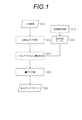
- FIG. 1 is a flowchart showing an overall flow of an image processing method according to an embodiment of the present invention.
- density correction unevenness correction
- quantization processing are performed on the input image (input image D10) (steps S12 to S20), and finally dot recording by the ink jet recording apparatus is performed. Is converted into a dot image (output dot pattern D22) suitable for the above.
- C cyan
- M magenta
- Y yellow
- K black
- the image separated for each color takes the correspondence between each nozzle and the position of the image (pixel position) in the single-pass inkjet recording apparatus, and then the recording position (main scanning direction) of each nozzle. Density conversion is performed for each raster (scanning line) corresponding to (position) (step S14, corresponding to “image correction process”).
- resolution conversion processing is performed as necessary in order to adjust the correspondence between each nozzle of the recording head and the pixels of the image data.
- gamma correction processing processing for correcting nonlinearity of input signal and output density is performed on the image data of each color.
- step S14 The density conversion process (step S14) for each raster (or nozzle) is performed with reference to the density correction table D18 reflecting the nozzle characteristics.
- the contents of the density correction process (step S16) for generating the density correction table D18 will be described later (see FIG. 2).
- the nonuniformity of the output image density is corrected by the density conversion process (step S14) using the density correction table D18.
- quantization is performed on the image that has been subjected to the image correction processing (density conversion processing in step S14) (corresponding to step S20, "quantization processing").
- the output dot pattern D22 generated by the quantization processing step S20 the ejection of the recording head of the ink jet recording apparatus is controlled to perform drawing.
- Step S16 ⁇ Density Correction Process (Step S16)>
- the density correction process (step S16 in FIG. 1) for generating the density correction table D18 the density non-uniformity in the paper feed vertical direction and the state of the nozzles (such as non-ejection and ejection bending) are read from the test chart printing result.
- a gradation table for correcting these density non-uniformities (look-up table showing the relationship between the output gradation value and the input gradation value) is generated for each raster (that is, for each nozzle).
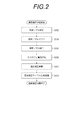
- Fig. 2 shows a flowchart of density correction processing.
- the density correction process in FIG. 2 is a process for generating a density correction table D18 (see FIG. 1) used for gradation conversion for correcting density unevenness due to the recording characteristics for each nozzle and recording defects (straight lines) due to non-ejection nozzles. is there.
- an abnormal nozzle is detected (corresponding to “abnormal nozzle detection process” step S32, “defect information acquisition process”).
- the position of the nozzle and the position of the image to be corrected need to correspond appropriately. For example, when the ejection from the nozzle is bent so much that the relationship between the nozzle position and the pixel position is broken (when the landing position is greatly deviated), processing different from normal is required. Further, when nozzle missing occurs, it is desirable to perform correction by a special method. In order to determine these discharge abnormalities, abnormal nozzles are detected in this process (step S32).
- abnormal nozzle here is, for example, non-ejection, large curvature, ejection droplet amount abnormality, ejection unstable nozzle, and the like. These abnormal nozzles are identified by, for example, drawing a line (line segment) for each nozzle, determining the amount of ejection bending (landing position error) from the drawing result of this line, and determining the presence or absence of a line line. can do.
- the abnormal nozzle corresponds to a “defective recording element”.
- the abnormal nozzle detected in the process of step S32 is processed according to each specification (steps S34 and S36). For example, a nozzle that is largely bent or a non-ejection nozzle is masked so as not to be used for drawing (as a nozzle forbidden to use) (corresponding to “abnormal nozzle mask process” step S34, “mask process process”). .
- a nozzle mask process corresponding to “abnormal nozzle mask process” step S34, “mask process process”.
- the density characteristic for each raster (or for each nozzle) is measured (“density detection step” step S38). For example, a flat mesh for each gradation is output to a recording medium (paper) over the entire drawing width (nozzle row width in the x direction) of the recording head, and the output result is read by an optical scanner, for each raster or for each nozzle ) To obtain the output density value of each gradation.
- a flat mesh for each gradation is output to a recording medium (paper) over the entire drawing width (nozzle row width in the x direction) of the recording head, and the output result is read by an optical scanner, for each raster or for each nozzle ) To obtain the output density value of each gradation.
- a density patch having a plurality of discrete gradation values with appropriate gradation steps (intervals) as input values can be output.
- the density value of each gradation for each raster can be obtained by outputting density patches with 8 gradation values in increments of “32”. Can be sought.
- the density value can be obtained by interpolating using the density values of the preceding and following gradations. In this way, with respect to all tone values (all defined areas), density characteristics representing the relationship between the input tone value and the output density are obtained for each raster (for each nozzle).
- step S38 Based on the density characteristics for each raster (for each nozzle) obtained in step S38, tables for reversing the read density characteristics (tone characteristics) so as to obtain a uniform density for each raster (for each nozzle) And stored as a density correction table ("Density correction calculation process" step S40, "Density correction table generation process” step S42).
- FIG. 4 shows a conceptual diagram of an image (corrected image) subjected to gradation conversion by applying the density correction table.
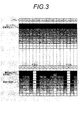
- FIG. 3 shows a density correction table in an initialized state (referred to as “original density correction table”), and the lower part of FIG. 3 shows density after density correction calculation generated by the flow of FIG. A conceptual diagram of the correction table is shown.
- the density correction table is configured as a lookup table that specifies the relationship between the input gradation and the output gradation for each raster (that is, for each nozzle).
- the horizontal axis in FIG. 3 represents the position of the nozzle. That is, each cell arranged in the horizontal direction of the illustrated table represents a position (nozzle position or raster position) corresponding to each nozzle (raster).
- the vertical direction (vertical axis) of the table indicates the input gradation, and the shade of each cell indicates the output gradation.
- FIG. 3 for simplification of illustration, cells for every 10 input gradation values are shown in the vertical direction of the table, but the actual table has gradation steps with a finer number of stages. For example, when a 256-gradation image signal is handled, output gradation values are associated with each input gradation value of 0-255 in the range of 0-255.
- the nozzle indicated by the symbol “x” is a nozzle detected as an abnormal nozzle, and is the position of a nozzle that becomes non-ejection (unusable) by mask processing.
- the density correction table after the density correction calculation created by the density correction processing described with reference to FIG. 2 is corrected to a value that increases the density of the pixels located on both sides of the masked nozzle. Further, the output gradation of each nozzle position is determined in accordance with the ejection characteristics of each nozzle in the nozzle row.
- the effect of image correction to which the density correction table after density correction calculation shown in the lower part of FIG. 3 is applied will be described with reference to FIG.
- the upper part of FIG. 4 is the original image data before correction (image before correction) to which the density correction table is applied, and the lower part of FIG. 4 is the image data after correction (image after correction) to which the density correction table is applied. ).
- the pre-correction image shown in the upper part of FIG. 4 is a uniform gradation image specified by the gradation value La.
- the output tone value at each nozzle position using the tone value La as the input tone value is defined in the cell group for one row surrounded by a broken line in the density correction table shown in the lower part of FIG. . Therefore, in the image after density correction, the gradation value of each raster is determined according to this density correction table, and is as shown in the lower part of FIG.
- the corrected image is corrected in density in units of pixel columns in the vertical direction (paper feed direction) in FIG. 4 to become a vertical stripe image, and the amplitude of light and shade near the raster corresponding to the masked nozzle. Becomes larger.
- the quantization process (step S20 in FIG. 1) in the present embodiment is performed with reference to a threshold matrix in which low frequency components in the raster direction (paper feed direction) where density correction is applied are suppressed. First, the characteristics of this threshold matrix will be described.
- the low frequency component in the paper feed direction in the quantization pattern is suppressed.
- interference of frequency components is suppressed, and as a result, artifacts and granular deterioration can be suppressed.
- the threshold matrix (dither matrix) used in this embodiment realizes a dot arrangement (quantization pattern) that suppresses low frequency components in the paper feed direction for a specific intermediate gradation range (corresponding to “at least a part of gradations”). To do.
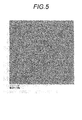
- FIG. 5 shows an example of a general quantization pattern of a certain intermediate gradation
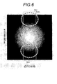
- FIG. 6 shows its frequency characteristics.
- the horizontal direction in FIG. 5 represents the paper feed direction
- the vertical direction is the paper feed vertical direction (nozzle arrangement direction).
- FIG. 6 shows a two-dimensional Fourier transform of the halftone pattern of FIG. 5, and in FIG. 6, the intensity of the frequency component is represented by shading.
- the horizontal direction in FIG. 6 represents the spatial frequency in the paper feed direction
- the vertical direction represents the spatial frequency in the paper feed vertical direction.
- FIG. 7A schematically shows FIG.
- FIG. 7A is a schematic diagram of a frequency spectrum of a general threshold matrix
- FIG. 7B is a sectional view in the paper feed direction of the frequency spectrum of FIG.
- the horizontal direction in FIG. 7A indicates the paper feed direction
- the vertical direction in FIGS. 7A and 7B indicates the paper feed vertical direction.
- a region in the vicinity of the vertical axis passing through the origin (0, 0) of the frequency space coordinate system shown in FIGS. 6 and 7A (a region surrounded by a broken-line rectangle denoted by reference numeral 564) corresponds to a low-frequency component in the paper feed direction.
- the area denoted by reference numeral 564 is referred to as a “paper feed direction low frequency component area”.
- a general quantization pattern has a frequency component (halftone component) in a portion where the density of the region surrounded by the thick wavy line of reference numeral 568 is darkly displayed in the low frequency component region 564 in the paper feed direction. That is, a halftone component is present in the low frequency component area 564 in the paper feed direction, whereby a beat (beat) is generated, the low frequency component is visually recognized, and the graininess is deteriorated.
- a halftone component is present in the low frequency component area 564 in the paper feed direction, whereby a beat (beat) is generated, the low frequency component is visually recognized, and the graininess is deteriorated.
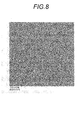
- FIG. 8 shows an example of a quantization pattern obtained from the threshold matrix according to the present embodiment
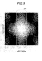
- FIG. 9 shows the frequency characteristics.
- the horizontal direction in FIG. 8 represents the paper feed direction
- the vertical direction is the paper feed vertical direction (nozzle arrangement direction).
- FIG. 9 shows a two-dimensional Fourier transform of the quantization pattern of FIG.
- the horizontal direction in FIG. 9 represents the component in the paper feed direction
- the vertical direction represents the paper feed vertical direction.
- FIG. 10A schematically shows FIG.
- FIG. 10A is a schematic diagram of a frequency spectrum of a threshold matrix according to the present embodiment
- FIG. 10B is a cross-sectional view in the paper feed direction of the frequency spectrum of FIG. 10A. 8 to 10 (a) and 10 (b) can be compared with FIGS. 5 to 7 (a) and 7 (b), respectively.
- the threshold value matrix In the case of the threshold value matrix according to the present embodiment, as shown in FIGS. 9 and 10A and 10B, all the paper feed directions in the area (paper feed direction low frequency component area) surrounded by the broken-line rectangle denoted by reference numeral 564 are shown. Regarding the vertical component (regardless of the component in the paper feed vertical direction), the low frequency component in the paper feed direction is suppressed. That is, in FIG. 9, there is almost no dark component in the paper feed direction low frequency component region surrounded by the broken-line rectangle denoted by reference numeral 564, or as shown in FIG. When the distribution is plotted, every cross-sectional line has a minimum value in a region corresponding to the low-frequency component region (reference numeral 564) in the paper feed direction.
- the suppression characteristic has a characteristic that the low frequency component in the paper feed direction is suppressed so as to reduce the beat due to the raster-like frequency characteristic and the frequency characteristic of the quantization pattern.
- the suppression characteristics are such that the first quantization pattern corresponding to the non-ejection vicinity region including the pixel row corresponding to the masked non-ejection nozzle and the pixel row adjacent thereto is in other regions. Compared to the second quantization pattern corresponding to a certain normal region, the paper feed direction low frequency component is suppressed for all the paper feed direction vertical components.
- the low frequency component in the paper feeding direction to be suppressed is 10 cycles / mm (10 cycles / mm) or less.
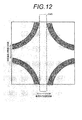
- FIGS. 9 to 10 Not only the frequency characteristics illustrated in FIGS. 9 to 10, but the frequency spectrum based on the threshold matrix of the present embodiment is only required to suppress the low frequency component in the paper feed direction, and the frequency spectrum illustrated in FIGS. 9 to 10. Other than that. Examples of other frequency spectra are shown in FIGS. A quantization pattern having a frequency spectrum as shown in FIG. 11 or 12 can be obtained.
- the threshold value matrix in which the low frequency component in the paper feeding direction (that is, the raster direction) is suppressed can be created by various methods.
- the creation method will be exemplified below.
- Outline of gradation pattern generation example An example of pattern generation for each gradation is shown in FIG.
- Each tone pattern generation process is based on a constraint condition, and an initial pattern (initial pattern generation process) generated by a random number is subjected to a pattern regarding an evaluation value through a process of sequentially replacing dots according to the constraint condition and the pattern evaluation value. It is generated by optimizing.
- the constraint condition is a condition that restricts the dot replacement processing position when the processing of replacing the position of the cell (pixel) where the dot is arranged is performed.
- FIG. 13 is a flowchart of processing for generating a pattern of each gradation. The components of the flowchart of FIG. 13 will be described below.
- step S61 an area in which dot replacement is allowed in the pixel replacement process (step S66) to be described later (that is, an area in which the dot arrangement can be changed by optimization using the evaluation value as an index).
- step S66 an area in which the dot arrangement can be changed by optimization using the evaluation value as an index.
- Dither matrix is a condition that is generally necessary.
- a high gradation pattern includes a low gradation pattern.
- (Restriction condition 2) A condition that restricts the positions where dots are placed in order to give the pattern specific characteristics for the purpose of improving image quality.
- the constraint condition 2 it is possible to apply a pattern having pattern characteristics in which the low frequency component in the paper feed direction is suppressed as the constraint condition 2. Since FIG. 16 also satisfies the suppression characteristic, a configuration in which this pattern is applied as a constraint condition is also possible. On the other hand, since the suppression characteristic can be realized in a process described later, a configuration in which the constraint condition 2 is not implemented is also possible.
- the evaluation filter setting process in step S62 is a process for designating an evaluation filter to be used in the pixel replacement process (step S66), the evaluation value calculation process (step S67), and the like.
- the evaluation filter is a frequency filter indicating a weight for each frequency component, and is used when the dot pattern is multiplied in the frequency space (convolved in the real space).
- the characteristic of this evaluation filter is reflected in the characteristic of the pattern. Therefore, in the present embodiment, it is possible to achieve the object by generating an evaluation filter that has pattern characteristics that suppress the low frequency component in the paper feed direction as a result of optimization.
- This evaluation filter is used in the following processing.
- step S66 it is used to specify the position of the dot to be replaced.
- step S67 Used to determine the evaluation value of the pattern in the evaluation value calculation process (step S67), the evaluation value comparison (step S68), and the storage pattern / evaluation value update process (step S69). Note that different evaluation filters can be set for each gradation. Details will be described later.
- the initial pattern generation process in step S63 in FIG. 13 sets an initial pattern when optimizing the pattern (dot arrangement).
- the pattern is set according to the following processing procedure.
- step S64 the counter value (n) is reset to “0”.
- step S66 the dot pattern is updated according to the flow illustrated in FIGS.
- the dot pattern is first multiplied (convolved) by an evaluation filter to calculate a density distribution for evaluation.
- the basic flow of replacing a dot that is in an area that satisfies the replacement constraint condition and that has a high density with a blank that has a low density is common.
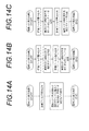
- FIG. 14A is a flow for performing the above process in one step.
- FIGS. 14B and 14C are examples of processing performed in two steps.
- the pixel replacement process (step S66) is repeatedly performed in the optimization process. For example, only the “pixel replacement process 1” illustrated in FIG. 14A may be performed, or the pixel replacement process illustrated in FIG.
- Each of the pixel replacement processes 1 to 3 may be selected at random, including “pixel replacement process 2” and “pixel replacement process 3” shown in FIG.
- the pixel replacement process 1 in FIG. 14A has a smaller number of evaluation filter convolutions than the other processes 2 to 3, and the calculation is fast, so that it may be frequently used at the initial stage of optimization. Further, the selection method of processes 1 to 3 may be changed for each gradation.
- the evaluation value calculation process in step S67, the evaluation value comparison process in step S68, and the storage pattern / evaluation value update process in steps S69 to S73 are as follows.
- Evaluation value calculation processing multiplies (convolutions) the dot pattern changed in the pixel replacement processing in step S66 with an evaluation filter to calculate a density distribution for evaluation. Then, a standard deviation of the concentration distribution is calculated and used as an evaluation value. If the pixel replacement process (step S66) and the evaluation value calculation process (step S67) are repeated in steps S66 to S72 and the evaluation value is improved in the evaluation value comparison (step S68), the relevant pattern and evaluation value are displayed. Save (step S69). After the next time, the stored evaluation value is compared with the calculated evaluation value (step S68), and it is determined whether or not the evaluation value has been improved.
- the gradation pattern is optimized with respect to the evaluation value.
- the gradation pattern obtained by the optimization is stored (step S73), and the process ends.
- threshold value matrix creation method A method of using a point spread function (PSF) and a low frequency filter will be described.
- the term “low frequency filter” as used herein refers to a filter that emphasizes or suppresses components below the cutoff frequency and maintains the components above the cutoff frequency. Appropriate processing is performed on the low-frequency component thus determined. Whether the component is emphasized or suppressed with respect to less than the cut-off frequency depends on the algorithm, and thus both modes are possible. In the following description, a filter that emphasizes components below the cutoff frequency will be exemplified.
- a target threshold matrix can be generated.
- an evaluation filter that emphasizes the low frequency component and the paper feed direction low frequency component is generated, and this evaluation filter is convolved with the above-described process (that is, the evaluation filter is convoluted with the dot pattern so that the multiplication result is flattened). (Repeating the replacement of the dot arrangement), a pattern in which the emphasized component disappears (flattened), that is, a pattern in which the low-frequency component in the feed direction is suppressed is generated.
- an evaluation filter (low frequency filter ⁇ fft (PSF)) is generated by multiplying a filter that emphasizes low frequency components (low frequency filter) and a filter that emphasizes low frequency components in the paper feed direction (PSF). The method is shown.
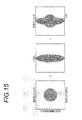
- FIG. 15 is a conceptual diagram of a method for generating an evaluation filter by multiplying a low-frequency filter and a PSF.
- the frequency characteristics of the low frequency filter, the PSF, and the evaluation filter are schematically shown, and the components of the frequency space emphasized by each filter are shown as gray portions.
- the low-frequency filter shown on the left side of FIG. 15 is to emphasize the low-frequency component isotropically for both the paper feed direction component and the paper feed vertical component.
- the PSF shown in the center of FIG. 15 emphasizes the low-frequency component of the paper feed direction component, and thus has an elliptical characteristic that is long in the paper feed vertical direction as shown. Since the evaluation filter shown on the rightmost side of FIG.
- the evaluation filter 15 is generated by multiplying the low frequency filter and the PSF, the evaluation filter has characteristics obtained by superimposing the characteristics of both.
- the gray portion component indicated by reference numeral 580 is emphasized by the evaluation filter. That is, the low frequency component indicated by reference numeral 580 emphasized by this evaluation filter is a component to be suppressed.
- FIG. 16 is a schematic diagram showing frequency characteristics of a pattern generated by applying the evaluation filter of FIG. As shown in FIG. 16, the generated pattern is one in which the component emphasized by the evaluation filter is suppressed.
- PSF real space
- the matrix shown in FIG. 17 can be used.
- the vertical direction in FIG. 17 is the paper feed direction
- the horizontal direction is the paper feed vertical direction.
- This matrix is a filter in which the paper feed direction component is emphasized to a higher frequency component than the vertical direction component by Fourier transform. Therefore, by applying such a filter, it is possible to generate a pattern that suppresses the low frequency component of the paper feed direction component to the higher frequency side.
- k 0 is a cut-off frequency, and is determined based on human visibility.
- Lo and n are fitting parameters and can take arbitrary real numbers, but it is desirable to use real numbers with Lo> 1 and n ⁇ 2, respectively.
- This filter becomes 1 when the cutoff frequency ko is higher than or equal to 1 and preserves the component.
- the filter gradually increases from 1 to L0 as it approaches 0, and emphasizes the component.
- IM (y, x) ifft (fft (img) * fft (PSF) * F (k))
- fft represents fast Fourier transform
- ifft represents fast inverse Fourier transform
- Step 2 Replace the part with the largest dot and the part without the smallest dot in the convolved pattern.
- Step 3 Calculate the evaluation value and save the pattern if the evaluation value is improved.
- FIGS. 14B and 14C can be used without being limited to the method described in “Example 1” above.
- the degree of suppression of the low frequency component in the paper feed direction can be changed by changing the low frequency filter and PSF applied in each gradation.
- the evaluation filter is made more isotropic (as an example, the isotropic low frequency filter is made more isotropic with PSF (real space) as shown in FIGS. 20 (a) and 20 (b)).
- the degree of suppression of the low-frequency component in the paper feed direction can be reduced by increasing the respective components of (1) and thereby reducing the anisotropic PSF weight as a result.
- a threshold matrix having the target pattern characteristics (characteristics in which the low frequency component in the paper feed direction is suppressed) described with reference to FIGS. 9 to 12 can be created.
- the frequency characteristics that suppress the low frequency characteristics in the paper feed direction described in FIGS. 9 to 12 are binarized after being applied to the white noise pattern, and the above pattern characteristics are maintained by setting the area as a dot arrangement candidate.
- a threshold matrix can be generated.
- the above characteristics can be changed by determining whether or not to impose the above-mentioned constraint conditions for each gradation.
- a sub-matrix that retains the characteristics of suppressing low frequency components in the paper feed direction, and determine the dot arrangement while preserving the number of dots in the sub-matrix. Thereby, since the dot arrangement can be determined while maintaining the characteristics of the sub-matrix, the suppression characteristics can be maintained at each gradation.
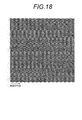
- the sub-matrix for example, a shape as shown in FIG. 18 can be used.
- FIG. 19 is a flowchart showing the flow of quantization processing according to this embodiment.
- the flow of FIG. 19 corresponds to the quantization process shown in step S20 of FIG.
- the quantization processing according to the present embodiment includes a pixel row corresponding to a masked non-ejection nozzle and a non-ejection vicinity region (corresponding to a “first image region”) including a pixel row adjacent thereto, Different quantization methods are applied to areas (hereinafter referred to as “normal areas”, which correspond to “second image areas”).
- the quantization method applied to the undischarge vicinity region will be referred to as a first quantization method
- the quantization method applied to the normal region will be referred to as a second quantization method.
- a pixel to be quantized is specified from the image data (step S82 in FIG. 19). Then, it is determined whether the target pixel (target pixel) is a pixel belonging to the non-discharge vicinity region or not (step S84).
- step S86 quantization (first quantization) by the first quantization method is performed (corresponding to “first quantization step” in step S86).
- step S84 if it is determined in step S84 that the target pixel belongs to the normal region, the process proceeds to step S88, and the target pixel is quantized by the second quantization method (second quantum). (Corresponding to “second quantization step”).
- step S86 or S88 after the target pixel is quantized, it is determined whether or not an unprocessed pixel remains (step S90). If unprocessed pixels remain in step S90, the process returns to step S82, the next pixel to be processed is specified, and the above-described processing (steps S82 to S90) is repeated.
- step S90 If the quantization process is completed for all the pixels of the image data and it is determined in step S90 that there are no unprocessed pixels, this process is terminated.
- the first threshold value matrix used for the first quantization and the second threshold value matrix used for the second quantization are both the spatial frequency characteristics described in FIGS. It is generated with reference to a common pattern having a suppressed pattern characteristic (suppressed characteristic), which corresponds to “first pattern characteristic”.
- the common pattern referred to here is, for example, a quantization pattern representing a uniform density image of a specific intermediate gradation (reference gradation L b ) serving as a reference. This pattern is called “common pattern” or “reference pattern”.
- the reference gradation L b can be selected an appropriate value, when the maximum gradation is 100%, it is preferable to select a tone of about 50%, that shifted slightly from 50% More desirable.
- the first threshold value matrix used in the non-discharge vicinity region maintains the suppression characteristics in more gradations (in a wide gradation region) than the second threshold value matrix used in the normal region. Yes. That is, the second threshold matrix is suppressed by reference gray L b gradation region defined by a gradation L c and the upper gradation L d of lower than (or less gradation L c or L d) Characteristics are maintained.
- the first threshold value matrix includes a gradation L e (L e ⁇ L c ) further lower than the gradation L c, and a gradation L f (L d ⁇ L f ) greater than or equal to the gradation L d. inhibiting properties in a wider gradation range defined (hereinafter gradation L e or L f) is maintained.
- Such a threshold matrix can be realized by changing the evaluation function when generating the pattern of each gradation.
- the reference gradations L b , gradations L c , L d , L e , L f are described above. These values can be set as appropriate while satisfying the relationship of Lmin ⁇ L e ⁇ L c ⁇ L b ⁇ L d ⁇ L f ⁇ L max.
- the gradation range where the first threshold value matrix and the second threshold value matrix both maintain the suppression characteristic corresponds to the “first gradation range”.
- a gradation range where only the threshold value matrix maintains the suppression characteristic (grayscale L e or more and less than L c or greater than the gradation L d and less than or equal to the gradation L f ) corresponds to the “second gradation range”.
- each gradation pattern (dot arrangement) is generated in the same manner as the common pattern, and the threshold matrix cell value is determined from each gradation pattern to generate the threshold matrix.
- the pattern is generated using, for example, the PSF described in FIG. 17, and for example, a more isotropic PSF is used.
- FIG. 20 (a) or FIG. 20 (b) As a specific example of a PSF that is more isotropic than the PSF of FIG. 17, the one shown in FIG. 20 (a) or FIG. 20 (b) can be used.
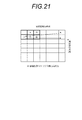
- FIG. 21 shows an example of an error diffusion matrix.
- “X” in the drawing represents the position of the quantization target pixel, and the arrow represents the processing order of the quantization processing.
- a quantization error is allocated to each of four unprocessed pixels (right side, diagonally right below, directly below, diagonally down left) adjacent to the target pixel (quantization target pixel x).
- the error component ("A" in the figure) to be diffused in the horizontal direction is a value (for example, divided into four equal parts). It is desirable that the distribution be larger than (a distribution ratio of 1/4). That is, in the case of FIG. 21, it is desirable to set the component “A” to a value larger than 0.25.
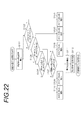
- FIG. 22 is a flowchart showing quantization processing for each pixel.
- dither [x] [y] represents a component of a two-dimensional dither matrix.
- th_edf [level] indicates an error diffusion threshold.
- the gradation value including the peripheral error is obtained by taking the sum of the original gradation value of the target pixel and the peripheral error diffused to the target pixel by error diffusion. Calculate (step S101).
- the image area is divided by comparing the dither matrix value (dither [x] [y]) with the threshold value th_dth [i] [level].
- the threshold th_dth [i] [level] is set for each gradation value (level) of the target pixel and is stored in advance in a predetermined memory.
- the third threshold th_dth [2] [level] are used to divide into four regions.
- the value of the dither matrix is compared with the first threshold th_dth [0] [level] (step S102). If the value of the dither matrix is smaller as a result of the comparison, the dot size specified by dot [0] [level] is selected (step S103).
- step S102 when the value of the dither matrix is equal to or greater than the first threshold value, the value of the dither matrix is subsequently compared with the second threshold value th_dth [1] [level] (step S104). If the value of the dither matrix is smaller as a result of the comparison, the dot size specified by dot [1] [level] is selected (step S105).
- step S104 if the value of the dither matrix is equal to or greater than the second threshold value, the value of the dither matrix is further compared with the third threshold value th_dth [2] [level] (step S106). If the value of the dither matrix is equal to or smaller than the third threshold th_dth [2] [level], the process proceeds to step S107, and the gradation value including the peripheral error is compared with the error diffusion threshold th_edf [level] (step S107). ).
- the error diffusion threshold th_edf [level] is also set for each gradation value of the target pixel and is stored in advance in a predetermined memory. If the gradation value including the peripheral error is smaller than the error diffusion threshold as a result of the comparison in step S107, the dot size specified by dot [2] [level] is selected (step S108).
- step S109 the dot size specified by dot [3] [level] is selected (step S109). As described above, in the region where the dither threshold is equal to or smaller than the third threshold (and equal to or greater than the second threshold), binarization processing by the error diffusion method is performed.
- step S106 if the value of the dither matrix is larger than the third threshold value, the dot size specified by dot [4] [level] is selected (step S110).
- each dot [j] [level] can be appropriately determined for each gradation value.
- dot [0] [level] is a small drop
- dot [1] [level] is a medium drop
- dot [2] [level] is no drop
- dot [3] [level] Is a large drop
- dot [4] [level] is a large drop.
- dot [3] [level]> dot [2] [level] is satisfied, and each value is determined so that a large dot is shot when the quantization error is large and a small dot is shot when the quantization error is small.
- the first threshold matrix is used, and when the target pixel is a pixel belonging to the normal region, the second threshold matrix is used for quantization.
- the quantization error is calculated (step S111).
- the quantization error is an error generated by quantizing the gradation value including the peripheral error, and is a difference between the gradation value including the peripheral pixel and the quantization threshold.
- a quantization threshold is associated with each dot [0] [level], dot [1] [level], dot [2] [level], dot [3] [level], and dot [4] [level]. Tone value.
- the calculated quantization error is diffused to surrounding pixels according to a predetermined error diffusion matrix (step S112). Subsequently, the quantization target pixel is shifted to an adjacent pixel, and the same processing is performed to quantize all the pixels.
- the recording rate of dot [0] [level], dot [1] [level], dot [4] [level] in each area corresponding to steps S103, S105, and S110 is dither.
- the remaining area is determined by binarization using an error diffusion method (steps S108 and S109).
- each threshold th_dth [i] [level] a threshold at the original gradation value of the target pixel is used, but a threshold at a gradation value including a peripheral error may be used.
- a dither / error diffusion method that uses a common threshold matrix in the non-discharge vicinity area and other areas (normal area) as a dither / error diffusion algorithm that uses a common threshold matrix in the non-discharge vicinity area and the normal area Uses the same flow as that shown in FIG.
- the “common threshold matrix” used here suppresses low-frequency components in the paper feed direction in a relatively wide gradation range (for example, gradation values Lmin to L f ) up to gradations with a small number of dots. The pattern characteristics are maintained (see FIG. 23).
- the gradation number of dots is small (e.g., highlight side than gradation Lmin or L c) in the number of dots is small gradation of the threshold matrix is not ⁇ near region (threshold matrix)
- Quantization is performed by referring to a threshold matrix pattern (dot arrangement realized by the threshold matrix) of a gradation close to a common pattern (for example, a reference gradation Lb or a gradation having a value close thereto) in a normal region. Then, quantization (binarization or multi-leveling) is performed by the error diffusion method under the constraint that dots can be placed in the threshold value matrix pattern.
- the "tone value close to the reference tone L b" the distribution form of dots to the extent that can be used as constraints dot arrangement means a range of gradation close.
- the number of dots is larger gradations (e.g., higher gradation L c) for the non ⁇ near region can refer quantization threshold of the threshold matrix in the normal region both.
- FIG. 23 exemplifies a ratio for each dot type in a halftone pattern realized by a common threshold value matrix.
- the horizontal axis represents the input signal value (gradation value), and the vertical axis represents the recording ratio (dot ratio) of small, medium, and large ink dots per unit area.
- the vertical axis in FIG. 23 represents the ratio of how many large, medium, and small ink dots are deposited in a pixel area (corresponding to “unit area”) that can eject ink of up to 100 pixels. Amount.
- the ratio of various dots to be used with respect to the input signal value can be appropriately designed depending on the specific setting of the quantization method.
- quantization by the error diffusion method is performed on the highlight side of the normal region (the gradation Lc or less).
- the dot arrangement of the normal area can be made substantially isotropic in the gradation area where the dots are arranged sparsely.
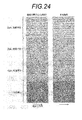
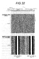
- FIG. 24 shows a comparison between a quantization pattern obtained by a conventional method (comparative example) and a quantization pattern obtained by image processing according to the present embodiment (example).
- a uniform image of the reference gradation L b as input tone values is illustrated in FIG. FIG. 24.
- FIG. 24 shows the case of non-ejection (nozzle missing), but the same effect can be obtained for artifacts when density correction is performed for density unevenness other than ejection failure. Since the streak due to undischarge has a larger amplitude of light and dark than density unevenness other than undischarge, artifacts are more likely to occur. Therefore, according to this embodiment, the effect of suppressing artifacts due to density unevenness other than undischarge can be obtained in the same manner as the effect of suppressing artifacts due to undischarge.
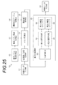
- FIG. 25 is a block diagram illustrating a configuration example of the image processing apparatus according to the present embodiment.
- the image processing apparatus 10 of the present embodiment includes an image data input unit 12, a color conversion / separation processing unit 14, a mask processing unit 16 (corresponding to “mask processing means”), and a density correction processing unit 18 (“image”).
- Correction nozzle ”), abnormal nozzle information acquisition unit 20 (corresponding to“ defective information acquisition unit ”), abnormal nozzle information storage unit 22, density correction table storage unit 24, and quantization processing unit 26 (“ quantum ”).
- an image data output unit 28 includes an image data input unit 12, a color conversion / separation processing unit 14, a mask processing unit 16 (corresponding to “mask processing means”), and a density correction processing unit 18 (“image”).
- Correction nozzle abnormal nozzle information acquisition unit 20 (corresponding to“ defective information acquisition unit ”), abnormal nozzle information storage unit 22, density correction table storage unit 24, and quantization processing unit 26 (“ quantum ”).
- quantum quantization processing unit
- the quantization processing unit 26 includes a region determination unit 30 that determines a region of a pixel to be processed, a first quantization unit 32 (corresponding to “first quantization unit”), and a second quantization unit 34. (Corresponding to “second quantizing means”).
- the first quantization unit 32 is a means for quantizing the pixels in the non-discharge vicinity region, and performs quantization by referring to the first threshold value matrix 36 (corresponding to “first quantization method”).
- the second quantization unit 34 is a means for quantizing pixels in a normal region other than the non-discharge vicinity region, and performs quantization by referring to the second threshold value matrix 38 (“second quantization method”). Equivalent).
- the characteristics of the first threshold value matrix 36 and the second threshold value matrix and the contents of the quantization processing are as described with reference to FIGS.
- the image data input unit 12 in FIG. 25 functions as a data acquisition unit for capturing image data.
- the image data input unit 12 can be configured by a data input terminal that takes in image data from the outside or another signal processing unit in the apparatus.
- the image data input unit 12 may employ a wired or wireless communication interface unit, or may employ a media interface unit that reads and writes an external storage medium (removable disk) such as a memory card. Alternatively, an appropriate combination of these aspects may be used.
- the image data (reference numeral D10 in FIG. 1) input from the image data input unit 12 is sent to the color conversion / separation processing unit 14, and the same color type as the ink color used in the ink jet recording apparatus as an output device, It is decomposed into gradation images for each color having the number of colors and resolution. For example, in the case of an ink jet recording apparatus that realizes an output resolution of 1200 dpi with CMYK four-color ink, image data of 8 bits (256 gradations) is obtained for each color of CMYK.
- the image data format of the image to be printed can be various.
- the color conversion / separation processing unit 14 performs resolution conversion, color conversion, and the like when handling image data specified by a combination of colors different from the type and resolution of the ink color used in the ink jet recording apparatus or a resolution format.
- the following configuration may be adopted instead of or in combination with the aspect.
- a configuration of inputting from the image data input unit 12 may be adopted.
- RGB image data when the original image data is RGB image data, RGB ⁇ CMYK color conversion processing or resolution conversion processing is performed with a RIP (Raster Image Processor) device or the like corresponding to the preprocessing unit, and RGB
- RIP Raster Image Processor
- the image data can be input to the image data input unit 12 after being converted into CMYK data (input image data) suitable for the ink jet recording apparatus.
- the mask processing unit 16 performs abnormal nozzle masking (non-ejection and non-use) processing based on the abnormal nozzle information stored in the abnormal nozzle information storage unit 22.
- the abnormal nozzle information is taken from the abnormal nozzle information acquisition unit 20 and stored in the abnormal nozzle information storage unit 22.
- the abnormal nozzle information acquisition unit 20 may include an abnormal nozzle detection unit that reads a test pattern print result and performs processing for detecting the position of the abnormal nozzle based on the result.
- the abnormal nozzle information acquisition unit 20 may include a reading device (for example, a scanner or a densitometer) that reads a test pattern print result.
- the abnormal nozzle information acquisition part 20 can also be comprised with the data input interface for taking in the information of the abnormal nozzle detected from the measurement result of the test pattern as data.
- the density correction processing unit 18 has a function of generating a density correction table and a correction function of performing image correction using the density correction table.
- the density correction table generated by the density correction processing unit 18 is stored in the density correction table storage unit 24.
- the density correction processing unit 18 performs density correction on the image data that has undergone mask processing using a density correction table.
- the image data corrected by the density correction processing unit 18 is sent to the quantization processing unit 26, and different quantization methods are applied to the non-discharge vicinity region and the normal region, respectively, and quantization is performed.
- the dot data generated by the quantization processing unit 26 is output from the image data output unit 28.
- the image data output unit 28 can be configured by a data output terminal that outputs image data to an external or other signal processing unit in the apparatus.
- the image data output unit 28 may employ a wired or wireless communication interface unit, or may employ a media interface unit that reads and writes an external storage medium (removable disk) such as a memory card. Alternatively, an appropriate combination of these aspects may be used.
- the first quantization unit 32 and the second quantization unit 34 can be configured by combining a threshold value matrix and error diffusion means as described with reference to FIGS.
- the second quantization unit 34 uses a threshold matrix common to the first threshold matrix 36 as described with reference to FIG. An error diffusion method using a threshold matrix pattern as a constraint condition can be adopted for the normal region in the key.
- each unit in the image processing apparatus 10 of this embodiment illustrated in FIG. 25 are hardware such as an integrated circuit, software (program) for operating a CPU (Central Processing Unit), or an appropriate combination thereof. Can be realized.
- a program for causing a computer to implement the processing functions described in this embodiment may be installed in advance in the computer, or a magnetic disk, an optical disk, a magneto-optical disk, a memory card, or other computer-readable medium storing the program. You may make it provide with a medium (information storage medium). Further, instead of providing the program by storing the program in such a tangible storage medium, the program signal can be provided as a download service using a communication network such as the Internet.
- FIG. 26 is a block diagram illustrating a configuration example of an image processing apparatus according to another embodiment.
- the image processing apparatus 100 shown in the figure can be applied to an image processing unit that generates an output image (halftone image) from input image data in an inkjet recording apparatus.
- the image processing apparatus 100 includes a system control unit 102 that performs overall control of the entire apparatus, an input image data acquisition unit 104 that acquires input image data, and an abnormal nozzle detection unit 106 that detects abnormal nozzles of an inkjet head (not shown). And an abnormal nozzle information storage unit 108 that stores abnormal nozzle information, and a mask processing unit 110 (mask processing means) that performs mask processing on the abnormal nozzles.
- a system control unit 102 that performs overall control of the entire apparatus
- an input image data acquisition unit 104 that acquires input image data
- an abnormal nozzle detection unit 106 that detects abnormal nozzles of an inkjet head (not shown).
- an abnormal nozzle information storage unit 108 that stores abnormal nozzle information
- the image processing apparatus 100 also includes a nozzle output characteristic information acquisition unit 112 that acquires output characteristic information of each nozzle, and a density correction LUT storage unit that stores the acquired nozzle output characteristic information in a lookup table format for each nozzle. 114 and a pixel value correction unit 116 (corresponding to “image correction means”) that corrects the pixel value of each pixel with reference to the density correction LUT.
- the density correction LUT storage unit 114 is a storage unit that stores the density correction table D18 described in FIG. 1, and corresponds to the density correction table storage unit 24 of FIG.
- the image processing apparatus 100 in FIG. 26 is used for a quantization processing unit 122 (quantization processing means) that performs quantization processing on the image data after density correction by the pixel value correction unit 116, and for the quantization processing.
- a threshold matrix storage unit 124 in which a threshold matrix is stored and a memory 128 are provided.
- the memory 128 is used as a primary storage area for data and a calculation area for each unit.
- the quantization processing unit 122 corresponds to the quantization processing unit 26 described with reference to FIG.
- Each part illustrated in FIG. 26 corresponds to each step of the image processing method described with reference to FIGS. 1 to 12, and thus detailed description thereof is omitted here.
- a parameter storage unit that stores various parameters and conversion tables used for processing (calculation) of each unit of the device and a program storage unit that stores programs (software) used for processing (calculation) of each unit of the device are provided. May be.
- FIG. 27 is a block diagram illustrating a main configuration of the image forming apparatus according to the present embodiment.
- the image forming apparatus 150 includes a recording head 160, a control device 170 (corresponding to “control unit”) that controls a recording operation by the recording head 160, and a paper transport unit 180 (corresponding to “relative movement unit”). Composed.
- control unit corresponding to “control unit”
- paper transport unit 180 corresponding to “relative movement unit”.
- the recording head 160 for one color is shown, but the image forming apparatus 150 includes a plurality of inkjet heads corresponding to each of a plurality of ink colors.
- the recording head 160 includes a plurality of piezoelectric elements 162 as ejection energy generating elements that generate ejection energy necessary for ink ejection corresponding to each nozzle, and each of the piezoelectric elements 162. And a switch IC 164 for switching between driving and non-driving.
- the number of nozzles, nozzle density, and nozzle arrangement form in the recording head 160 are not particularly limited, and various forms are possible.
- a one-dimensional nozzle array in which a large number of nozzles are arranged in a straight line (in a line) at regular intervals may be used, or two nozzle arrays may be connected to each other.
- a so-called staggered arrangement may be employed in which each nozzle row is shifted in the nozzle row direction by a half pitch of the nozzle interval (inter-nozzle pitch).
- a configuration in which a large number of nozzles are two-dimensionally arranged on the ink ejection surface (nozzle surface), such as a matrix arrangement in which three or more nozzle rows are arranged, can be employed.
- the projected nozzle array in which the nozzles in the two-dimensional nozzle array are projected (orthographically projected) so as to be aligned along the paper width direction (corresponding to the main scanning direction)
- the paper width direction corresponding to the main scanning direction
- the projected nozzle array in which the nozzles in the two-dimensional nozzle array are projected (orthographically projected) so as to be aligned along the paper width direction (corresponding to the main scanning direction)
- medium width direction it can be considered that this is equivalent to a nozzle row in which nozzles are arranged at approximately equal intervals at a nozzle density that achieves recording resolution.
- “equal intervals” means substantially equal intervals as the droplet ejection points that can be recorded by the ink jet printing system.
- the concept of “equally spaced” also includes cases where the intervals are slightly different in consideration of manufacturing errors and movement of droplets on the medium due to landing interference.
- nozzle positions can be associated with the order of projection nozzles arranged along the main scanning direction.
- the term “nozzle position” refers to the position of the nozzle in this substantial nozzle row.
- the control device 170 includes a system control unit 171, an image data input unit 172 that functions as an input interface unit that receives original image data (multi-tone image data) of an image to be recorded, and input image data.
- An image processing unit 174 that performs density correction and quantization processing is provided.
- the control device 170 includes a drive waveform generation unit 176 and a head driver 178.
- the processing content in the image processing unit 174 is as described with reference to FIGS.
- the image processing unit 174 is a signal processing unit that converts input image data into binary or multi-value dot data.
- the means for the quantization process halftone process
- the aspect using the threshold matrix already described, the aspect combining the threshold matrix and the error diffusion method, or the like can be applied.
- Quantization processing generally converts M-value (M is an integer of 3 or more) gradation image data into N-value (N is an integer of 2 or more and less than M) gradation image data.
- M is an integer of 3 or more
- N is an integer of 2 or more and less than M
- the image data is converted into binary (dot on / off) dot image data.
- the dot size types for example, three types such as large dots, medium dots, and small dots
- the binary or multi-valued image data (tot data) generated by the image processing unit 174 is driven (on) / non-driven (off) for each nozzle. This is used as ink ejection control data (droplet ejection control data) for controlling the size.
- the dot data (droplet ejection control data) generated by the image processing unit 174 is given to the head driver 178, and the ink ejection operation of the recording head 160 is controlled.
- the drive waveform generation unit 176 is a means for generating a drive voltage signal waveform for driving the piezoelectric element 162 corresponding to each nozzle of the recording head 160.
- the waveform data of the drive voltage signal is stored in advance in storage means such as a ROM, and waveform data to be used is output as necessary.
- the signal (drive waveform) generated by the drive waveform generation unit 176 is supplied to the head driver 178. Note that the signal output from the drive waveform generation unit 176 may be digital waveform data or an analog voltage signal.
- the image forming apparatus 150 shown in this example supplies a common drive power waveform signal to each piezoelectric element 162 of the recording head 160 via the switch IC 164, and the corresponding piezoelectric element according to the ejection timing of each nozzle.
- a driving method is employed in which ink is ejected from nozzles corresponding to each piezoelectric element 162 by switching on / off the switching elements connected to the individual electrodes 162.
- the recording head 160 ejects ink droplets on demand in accordance with the drive signal and ejection control signal provided from the head driver 178.
- a combination of the system control unit 171, the image data input unit 172, and the image processing unit 174 in FIG. 27 corresponds to an “image processing apparatus”.
- the system control unit 171 controls the paper transport unit 180 via the paper transport control unit 182. Thereby, a sheet (recording medium) (not shown) is conveyed to the recording head 160.
- the sheet conveyance control unit 182 and the sheet conveyance unit 180 correspond to “relative movement means”.
- FIG. 28 is an overall configuration diagram of the ink jet recording apparatus according to the embodiment of the present invention.
- the ink jet recording apparatus 300 shown in FIG. 1 has a recording medium conveyance unit 304 that holds and conveys a recording medium 302 (corresponding to “recording medium”), and a recording medium 302 that is held by the recording medium conveyance unit 304.
- a printing unit 307 including inkjet heads 306K, 306C, 306M, and 306Y that discharge each color ink of K, C, M, and Y.
- the recording medium transport unit 304 corresponds to “relative movement means”.
- the recording medium conveyance unit 304 includes an endless conveyance belt 308 provided with a plurality of suction holes (not shown) in a recording medium holding area where the recording medium 302 is held, and a conveyance roller (drive) around which the conveyance belt 308 is wound. Roller 310, driven roller 312) and a back side of the conveyance belt 308 in the recording medium holding area (a surface opposite to the recording medium holding surface on which the recording medium 302 is held), and a non-printing area provided in the recording medium holding area.
- a chamber 314 communicated with the illustrated suction hole and a vacuum pump 316 that generates a negative pressure in the chamber 314 are included.
- the carry-in unit 318 into which the recording medium 302 is carried is provided with a pressing roller 320 for preventing the recording medium 302 from floating, and the discharge roller 324 from which the recording medium 302 is discharged is also provided with a pressing roller 324. It has been.
- the recording medium 302 carried in from the carry-in section 318 is applied with negative pressure from the suction holes provided in the recording medium holding area, and is sucked and held in the recording medium holding area of the conveyor belt 308.
- a temperature adjusting unit 326 for adjusting the surface temperature of the recording medium 302 to a predetermined range is provided on the upstream side of the printing unit 307 (upstream side in the recording medium conveyance direction).
- a reading device (reading sensor) 328 for reading an image recorded on the recording medium 302 is provided on the rear side of the recording medium 307 (downstream in the recording medium conveyance direction).
- the recording medium 302 carried in from the carry-in section 318 is sucked and held in the recording medium holding area of the transport belt 308 and subjected to temperature adjustment processing by the temperature adjustment section 326, and then image recording is performed in the printing section 307.
- each color ink of KCMY is ejected onto the recording medium 302 to form a desired color image. Is done.
- the printing unit 307 is not limited to the above-described form.
- an inkjet head corresponding to LC (light cyan), LM (light magenta), or other special color ink may be provided.
- the arrangement order of the inkjet heads 306K, 306C, 306M, and 306Y can be changed as appropriate.
- the recording medium 302 on which the image is recorded by the printing unit 307 is discharged from the discharge unit 322 after the recorded image (including the test pattern) is read by the reading device 328.
- the reading result of the reading device 328 is used for determination of ejection abnormality of the inkjet heads 306K, 306C, 306M, and 306Y and generation of a density correction table.
- the ink jet recording apparatus 300 includes an ink supply unit.
- the ink supply unit includes an ink tank for each color (each head) that stores ink to be supplied to each of the inkjet heads 306K, 306C, 306M, and 306Y.
- Each of the ink tanks for each color and the inkjet heads 306K, 306C, 306M, and 306Y communicate with each other through an ink supply path (not shown).
- FIG. 29 is a perspective plan view showing a structural example of an inkjet head (a diagram seen from the side opposite to the ink ejection surface). Since the inkjet heads 306K, 306C, 306M, and 306Y of the printing unit 307 can apply the same structure, here, the head is representatively described with a common reference numeral 306.
- the ink jet head 306 is an ejection element (recording element) including a plurality of nozzles 350 and pressure chambers 352 over a length corresponding to the entire width of the recording medium 302 in the main scanning direction (x direction).
- This is a page-wide full-line head in which 354 is arranged.
- a recorded image can be recorded over the entire area of the recording medium 302 by a single-pass method in which the full-line inkjet head 306 and the recording medium 302 are moved relatively once.
- the inkjet head 306 shown in FIG. 29 has a plurality of nozzles 350 (ejection elements 354) along a row direction along the main scanning direction (x direction) and an oblique column direction that is not orthogonal to the sub scanning direction (y direction). It has a structure arranged in a matrix. By arranging the plurality of nozzles 350 in a matrix in this way, the substantial nozzle arrangement density in the main scanning direction (x direction) is increased.
- the nozzle arrangement of the inkjet head is not limited to the matrix arrangement shown in FIG.
- the inkjet head 306 to which the piezoelectric method is applied includes a piezoelectric element 162 on at least one wall surface of the pressure chamber 352 communicating with the nozzle 350.
- the piezoelectric element 162 has a structure in which a piezoelectric body is sandwiched between an upper electrode and a lower electrode, and bending deformation occurs when a driving voltage is applied between the upper electrode and the lower electrode. As the pressure chamber 352 is deformed, the ink stored in the pressure chamber 352 is ejected from the nozzle 350.
- an inkjet head to which a thermal method is applied includes a heater that heats ink contained in a pressure chamber (liquid chamber) 352, and bubbles are generated by instantaneously heating the ink in the pressure chamber 352. And the ink is ejected from the nozzle 350.
- FIG. 30 is a block diagram illustrating a schematic configuration of a control system of the inkjet recording apparatus 300.
- the inkjet recording apparatus 300 includes a communication interface 360, a system control unit 362, a conveyance control unit 364, an image processing unit 366, a head driving unit 368, and an image memory 370, a ROM 372, and the like. .
- the communication interface 360 is an interface unit that receives image data sent from the host computer 374.
- the communication interface 360 may be a serial interface such as USB (Universal Serial ⁇ Bus) or a parallel interface such as Centronics.
- the communication interface 360 may include a buffer memory (not shown) for speeding up communication.
- the system control unit 362 includes a central processing unit (CPU) and its peripheral circuits, and functions as a control device that controls the entire inkjet recording apparatus 300 according to a predetermined program, and also functions as an arithmetic device that performs various calculations. Further, it functions as a memory controller for the image memory 370 and the ROM 372.
- CPU central processing unit
- the system control unit 362 controls each unit such as the communication interface 360, the conveyance control unit 364, and performs communication control with the host computer 374, read / write control of the image memory 370 and the ROM 372, and the above-described units.
- a control signal to be controlled is generated.
- Image data (recorded image data) sent from the host computer 374 is taken into the inkjet recording apparatus 300 via the communication interface 360 and subjected to predetermined image processing by the image processing unit 366.
- the image processing unit 366 has a signal (image) processing function for performing various processing and correction processes for generating a print control signal from the image data.
- the generated print data (dot data) is transferred to the head drive unit.
- 368 is a control unit to be supplied to 368.
- the head driving unit 368 may include a feedback control system for keeping the driving conditions of the inkjet head 306 constant.
- control system of the ink jet recording apparatus 300 shown in FIG. 30 can be shared as appropriate with each configuration shown in FIG.
- the conveyance drive unit 376 includes a motor that drives the drive roller 310 (312) of the recording medium conveyance unit 304 that conveys the recording medium, and the conveyance control unit 364 functions as a driver of the motor.
- An image memory (temporary storage memory) 370 functions as a temporary storage unit that temporarily stores image data input via the communication interface 360, a development area for various programs stored in the ROM 372, and a calculation work area for the CPU. (For example, a work area of the image processing unit 366).
- the image memory 370 is a volatile memory (RAM) that can be read and written sequentially.
- the ROM 372 stores a program executed by the CPU of the system control unit 362, various data necessary for controlling each unit of the apparatus, control parameters, and the like, and data is read and written through the system control unit 362.
- the ROM 372 is not limited to a memory made of a semiconductor element, and a magnetic medium such as a hard disk may be used. Alternatively, a removable storage medium that includes an external interface may be used.
- the parameter storage unit 378 stores various control parameters necessary for the operation of the inkjet recording apparatus 300.
- the system control unit 362 appropriately reads out parameters necessary for control and updates (rewrites) various parameters as necessary.
- the program storage unit 380 is a storage unit that stores a control program for operating the inkjet recording apparatus 300.
- the system control unit 362 or each unit of the device executes control of each unit of the device, a necessary control program is read from the program storage unit 380, and the control program is appropriately executed.
- the display unit 382 is a means for displaying various information sent from the system control unit 362, and a general-purpose display device such as an LCD monitor is applied. Note that lighting (flashing and extinguishing) of the lamp may be applied to the display form of the display unit 382. Further, sound (sound) output means such as a speaker may be provided.
- information input means such as a keyboard, a mouse, and a joystick are applied.
- Information input via the input interface 384 is sent to the system control unit 362.
- the conveyance of the recording medium is not limited to the belt conveyance method, and other conveyance methods such as a drum conveyance method and a roller conveyance method can be applied.
- FIG. 31 is an overall configuration diagram showing a schematic configuration of an inkjet recording apparatus 400 to which a drum conveyance method is applied for conveyance of a recording medium.
- a recording medium (not shown in FIG. 31) is fixed to the outer peripheral surface of the drawing drum 414, and recording is performed along the outer peripheral surface of the drawing drum 414 by rotating the drawing drum 414.
- a conveyance method for rotating and conveying a medium is applied.
- the inkjet heads 416K, 416C, 416M, and 416Y are disposed along the outer peripheral surface of the drawing drum 414 so as to be inclined with respect to the horizontal plane.
- the configurations of the inkjet heads 306K, 306C, 306M, and 306Y illustrated in FIG. 29 can be applied to the inkjet heads 416K, 416C, 416M, and 416Y that configure the printing unit 417.
- the recording medium sent out from the paper supply unit (not shown) is held by the transfer drum 428 and transferred to the drawing drum 414.
- the recording medium on which the image is formed by the printing unit 417 is transferred from the drawing drum 414 to the transfer cylinder 432 on the rear stage side.
- an image forming pre-process such as a recording medium pre-processing process
- a post-process such as a drying process or a fixing process
- the configuration of the ink jet recording apparatus described with reference to FIGS. 28 to 31 is an example, and it is possible to add, delete, and change the configuration as appropriate.
- Recording medium is a generic term for media on which dots are recorded by a recording head, and includes what are called by various terms such as recording media, printing media, recording media, image forming media, image receiving media, and ejection media. It is.
- the material, shape, etc. of the recording medium are not particularly limited, and a print on which a resin sheet such as continuous paper, cut paper, seal paper, OHP sheet, film, cloth, nonwoven fabric, wiring pattern, or the like is formed. It can be applied to various media regardless of the substrate, rubber sheet, and other materials and shapes.
- ⁇ Application example of device> application to an inkjet recording apparatus for graphic printing has been described as an example, but the scope of application of the present invention is not limited to this example.
- a wiring drawing apparatus for drawing a wiring pattern of an electronic circuit a manufacturing apparatus for various devices, a resist recording apparatus that uses a resin liquid as a functional liquid for ejection, a color filter manufacturing apparatus, and a material deposition material.
- the present invention can be widely applied to an inkjet apparatus that draws various shapes and patterns using a liquid functional material, such as a fine structure forming apparatus that forms a structure.
- an ink jet recording apparatus is illustrated as an example of an image forming apparatus using a recording head, but the scope of application of the present invention is not limited to this.
- a thermal transfer recording apparatus including a recording head using a thermal element as a recording element
- an LED electrophotographic printer including a recording head using an LED element as a recording element
- a silver salt photographic printer including an LED line exposure head
- the present invention can also be applied to various types of image forming apparatuses that perform dot recording.
- DESCRIPTION OF SYMBOLS 10 ... Image processing apparatus 12 ... Image data input part 16 ... Mask processing part 18 ... Density correction processing part 20 ... Abnormal nozzle information acquisition part 22 ... Abnormal nozzle information storage part 24 ... Density correction table storage part 26 ... Quantization processing part 30 ... area determination unit 32 ... first quantization unit 34 ... second quantization unit 100 ... image processing device 106 ... abnormal nozzle detection unit 110 ... mask processing unit 114 ... density correction LUT storage unit 116 ... pixel value correction unit 122 ... Quantization processing unit 124 ... Threshold matrix storage unit 150 ... Image forming device 160 ... Recording head 170 ... Control device 178 ... Head driver 180 ... Paper transport unit 300 ...
- Inkjet recording device 302 ... Recording medium 304 ... Recording medium transport unit 306K, 306C, 306M, 306Y ... inkjet head 350 ... nozzle 362 ... system control unit 364 ... transport control 376 ... transfer drive 368 ... head driving unit 400 ... ink jet recording apparatus 414 ... print drum 416K, 416C, 416M, 416Y ... inkjet head
Landscapes
- Engineering & Computer Science (AREA)
- Multimedia (AREA)
- Signal Processing (AREA)
- Quality & Reliability (AREA)
- General Engineering & Computer Science (AREA)
- Physics & Mathematics (AREA)
- General Physics & Mathematics (AREA)
- Theoretical Computer Science (AREA)
- Ink Jet (AREA)
- Particle Formation And Scattering Control In Inkjet Printers (AREA)
- Color, Gradation (AREA)
- Facsimile Image Signal Circuits (AREA)
Abstract
記録ヘッドの記録素子に不良が発生した場合でも、アーティファクトの発生や粒状の悪化を抑えて、高品位の画像を生成する画像処理装置及び方法、プログラム並びに画像形成装置を提供する。マスク処理された不良記録素子に対応する画素列に隣接する画素列の画像濃度を補正し、マスク処理された不良記録素子に対応する画素列及びこれに隣接する画素列を含む第1の画像領域と、それ以外の第2の画像領域について異なる量子化を行う。少なくとも一部の階調において、第1の画像領域に適用する第1の量子化方法により得られる第1の量子化パターンは、第2の画像領域に適用する第2の量子化方法により得られる第2の量子化パターンと比較して、記録ヘッドに対する記録媒体の相対移動方向と平行な第1の方向の空間周波数成分が、第1の方向と直交する第2の方向のすべての空間周波数成分に対して抑制されたパターン特性を持つ。
Description
本発明は画像処理装置及び方法、プログラム並びに画像形成装置に係り、特に、インクジェット記録装置などドットの記録によって階調表現を行うためのデジタルハーフトーニング技術に関する。
画像形成装置の一つであるインクジェット記録装置は、複数のインク吐出口(ノズル)が配列された記録ヘッドと用紙(記録媒体)とを相対移動させ、ノズルからインク滴を吐出することにより、用紙上に所望の画像を形成する。高精細な画像出力を実現するために、記録ヘッドには、多数のノズルを2次元的に配列させたノズルレイアウトにより記録解像度を向上させた2次元ノズル配列ヘッドが用いられる。
また、プリント生産性を高めるために、用紙の送り方向(以下「紙送り方向」又は「y方向」という。)に直交する用紙幅方向(以下「紙送り垂直方向」又は「x方向」という。)について描画領域の全範囲をカバーするノズル配列を備えた長尺のラインヘッドを用い、このラインヘッドに対して記録媒体を1回だけ相対移動させることにより、記録媒体上に所定解像度の画像を形成するシングルパス方式の構成も知られている(特許文献1~3)。
シングルパス方式のインクジェット記録装置では、吐出曲がりや不吐出などの吐出異常により、用紙送り方向に沿ったスジ状のムラ(スジムラ)が発生することがある。その対策として、異常ノズルをマスクして打滴に使用しないものとし、その異常ノズルが本来記録すべき画素の両脇の記録位置について印刷濃度を上げて、スジの視認性を低下させる画像補正が行われる。このような画像補正は「ムラ補正」或いは「濃度補正」などと呼ばれる。本明細書では濃度補正という用語を用いる。
図32は濃度補正の概念図である。図32において、符号500はラインヘッドのノズル列を表し、符号510-i(i=1,2,…17)はx方向に沿って並ぶ各ノズルを表している。図中の符号510-5で示したノズルと、510-15で示したノズルが吐出異常ノズルであり、これらのノズルはマスクして記録に使用しないものとし、不吐出ノズルとして扱う。
図32では、濃度補正前の画像(符号520)として、各ノズルに対応した画素位置について一定の入力階調値の均一濃度画像が例示されている。
図32の下段に示した符号530は濃度補正後の画像を表している。不吐出ノズル510-5、510-15はマスクされ、これら不吐出ノズル510-5、510-15に対応する画像位置540-5、540-15の画素列は無記録となり、その左右両側の隣接画素の位置(540-4、540-6、及び540-14、540-16)の画素列について、画像濃度を高めるように信号値の補正が行われる。したがって、濃度補正後の画像530は、不吐出ノズルに対応する画像位置540-5、540-15の左右両脇の画素列(符号540-4、540-6、540-14、540-16の位置)の画像濃度が濃くなる。
このような濃度補正後の画像530について、ディザ法や誤差拡散法などのハーフトーン処理(量子化処理)が行われ、2値又は多値のドットデータに変換され、このドットデータに基づいて各ノズルの吐出制御が行われる。
しかし、このように特定ノズルをマスクすると、マスクした部位のハーフトーン形状が崩れることにより、粒状悪化やアーティファクト(虚像または偽像)発生という画質劣化を招く。これは濃度補正ないしマスクによる、ラスタ状の周波数特性と、量子化パターンの周波数特性に起因するビートとして理解することができる。
ビートとは、近接した周波数の波を重ねると、元の周波数差に対応するうなりが発生することである。例えば、周波数f1と周波数f2の波が重なると、周波数|f1-f2|のうなりが発生する。仮に、f1とf2が近い場合は、うなりの周波数は0に近くなるので、低周波なうなりが発生する。
図32の符号530で示したように、量子化処理は、紙送り方向に沿った走査線(ラスタ)と平行なラスタ状の濃度補正後の画像に対して行われるため、量子化パターンの空間周波数成分と、濃度補正後の画像の空間周波数成分に関しても同様にビート現象が発生する。すなわち、量子化パターンとラスタ状の濃度補正後の画像が、近接した周波数成分を保持していると、その差分に対応する低周波なうなりが発生し、これが粒状悪化ないしアーティファクトとして視認される。ラスタ状の濃度補正後の画像に従来の一般的な量子化処理を適用すると、一般に上記の問題が発生する。
図33は一般的な量子化パターンの周波数特性を模式的に示したものである。縦軸は紙送り方向(ラスタ方向)の空間周波数、横軸は紙送り方向と直交する方向(以下、紙送り垂直方向という。)の空間周波数を示している。図33において、周波数成分を濃淡で表しており、図中の灰色部550が一般的な量子化パターンの周波数特性を示している。
人の目の視覚特性は、略等方的でありかつ高周波なほど視認しない特性を有する。そのため、図33の灰色部550で示したように、低周波領域には成分を持たず(図33の白部分)、高周波な領域には等方的に成分を持つようにパターンを生成すると、ドットのパターンを極力視認させないように中間階調を表現することが可能である。従来の一般的なハーフトーン処理はこのような周波数特性(図33)を持つ量子化パターンを生成する。
次に、濃度補正について考察する。図32で説明したように、濃度補正では、補正前の画像520の画像データを紙送り方向と平行な縞々の濃度分布の画像(濃度補正後の画像530)に変換する。
これを図33の周波数空間で見ると、補正前の画像は符号560の破線円で囲んだ領域に周波数成分を持つ。つまり、ラスタ状の濃度補正無し(補正前)の場合のハーフトーン入力画像成分は、破線円560で囲んだ範囲のものとなる。
一方、ラスタ状の濃度補正を行った補正後の画像(符号530)は、紙送り方向には均一濃度であるので、紙送り方向の周波数成分が必ず「0」の箇所のどこかに周波数成分のピークが発生する。
紙送り垂直方向に関しては、読み込んだ画像のムラ(スジムラと濃度ムラを包括して「ムラ」と呼ぶ。)の状態に依存し、その周波数特性はランダム、若しくは機械に依存する。どちらにせよラスタ状の濃度補正では図33の符号564で示した領域(紙送り方向周波数ky=0(縦)付近の領域)のどこかに成分のピークを持つ。
以上から、一般的な量子化処理により得られる量子化パターンは、図33の灰色部550に成分を持ち、ラスタ状の濃度補正された画像は符号564で示す領域内に成分を持つことが分かる。したがって、両者の重複領域、つまり、図33の符号568で示す一点鎖線で囲んだ領域に関しては、ラスタ状の濃度補正後画像と、量子化パターンとがともに成分を持っていることが分かる。
ラスタ状の濃度補正無しの場合(符号560)は、量子化パターンの成分(灰色部550)と互いに近しい成分がないので目で見えるビートは発生しない。その一方で、ラスタ状の濃度補正をかけたことにより、互いに近しい成分(符号568で囲んだ領域)が生成され、これらは周波数帯が近いので、干渉により低周波なうなりが発生する。すなわち、ラスタ状の濃度補正と一般的な量子化パターンを組み合わせたことによりアーティファクトが発生する。
特許文献1~3では、濃度補正をかけると粒状が悪化するという課題について言及しているが、必ずしも上記課題(ビートによるうなり)に対して十分に対応できていない。
特許文献1では、各ノズルの特性をもとに閾値マトリクスの値を変更することでスジ部の濃度補正(本明細書でいう「ラスタ状の濃度補正」に相当)を行い、かつ同一列内で閾値を置換することで粒状の悪化を抑制する技術が開示されている。この方法では、同一列(紙送り方向)のみで見た場合の粒状悪化は改善する可能性があるが、紙送り垂直方向の任意の位置にスジが発生した際に濃度補正を行った場合の粒状悪化に対応することができない。特にスジムラが高周波かつランダムな場合や、不吐出が密に発生する場合は、図33の符号568で説明した領域にラスタ補正成分が発生する。この場合、量子化パターンとラスタ状の補正に起因するうなりは、紙送り垂直方向にも発生するが、閾値マトリクスの置き換え補正は紙送り方向のみに行われるので、結果として紙送り垂直方向のアーティファクトを除去することはできない。
また特許文献2では、ノズル抜け(不吐出ノズル)が発生した場合の画質低下の程度を評価しながらドット配置の最適化を行うことで、ノズル抜けによってアーティファクトの発生が起こりにくいパターン生成方法が開示されている。この最適化によって求められるドット配置は上記課題に対して、良好な結果を得る可能性がある。
しかし、特許文献2の最適化によって得られるドット配置は、予め想定されたノズル抜けのみに最適化されているため、任意周期のスジムラが発生した場合にアーティファクト発生しないことを保証するものではない。また特許文献2ではパターン最適化が基本的には等方的な粒状評価値及び異方性評価値に関して行われているため、最適化された量子化パターンは図33のような一般的な量子化パターンの周波数特性を持つ傾向にある。したがって、図33の符号568で示した領域の成分が少なからず残ることとなるため、上記課題のビートによるアーティファクトを完全に抑制することはできない。
一方で特許文献3においては、ドットパターンの少なくとも主走査方向(本明細書でいう「紙送り垂直方向」に相当)に関する周波数成分が弱められた閾値マトリクスが提案されている。この特許文献3においては、スジムラ補正特有の課題に関して考慮されていないが、この閾値マトリクスを転用することでノズル抜けによるアーティファクトを抑制できる可能性がある。
しかし、全階調においてこのようなアーティファクトを抑制するような周波数特性を持つ閾値マトリクスを生成した場合、ノズル抜けが発生している部分以外の正常な領域においてもこの閾値マトリクスを使用すると、特にドットが少ない領域において著しく粒状が悪化する。これはドットが少ない領域では等方的な周波数特性を持ったパターンの方が、粒状が良いためである。すなわち、特許文献3の方法では、ノズル抜けによるアーティファクトの抑制と、粒状悪化の抑制とを両立できない。
上記の課題はインクジェット記録装置に限らず、ドットの記録によって階調表現を行う画像形成装置に共通の課題として把握される。
本発明はこのような事情に鑑みてなされたものであり、任意の空間周期で多数のスジムラやノズル抜け(記録素子の不良)が発生した場合であっても、若しくはこれらが発生しない場合に関しても、アーティファクトの発生や粒状の悪化なく、高品位の画像生成が可能な画像処理方法及び装置、プログラム並びに画像形成装置を提供することを目的とする。
上記の課題を解決するために、次の発明を提供する。
(第1態様) :複数の記録素子が配列された記録ヘッドにおける不良記録素子の情報を取得する不良情報取得工程と、不良情報取得工程で取得した不良記録素子情報に基づき不良記録素子を使用不能にするマスク処理を行うマスク処理工程と、入力画像データのうちマスク処理された不良記録素子に対応する画素列に隣接する画素列の画像濃度を補正して、マスク処理に伴うスジ状の画像欠陥の視認性を下げる画像補正工程と、画像補正工程による濃度補正後の画像データを量子化し、濃度補正後の画像データよりも階調数の少ない2値又は多値の画像データに変換する量子化処理工程と、を含み、量子化処理工程は、マスク処理された不良記録素子に対応する画素列及び前記不良記録素子に対応する画素列に隣接する画素列を含む第1の画像領域について第1の量子化方法を適用して量子化を行う第1の量子化工程と、第1の画像領域以外の第2の画像領域について第1の量子化方法とは異なる第2の量子化方法を適用して量子化を行う第2の量子化工程と、を有し、少なくとも一部の階調において、第1の量子化方法を適用した量子化によって得られる第1の量子化パターンは、第2の量子化方法を適用した量子化によって得られる第2の量子化パターンと比較して、記録ヘッドに対する記録媒体の相対移動方向と平行な第1の方向の空間周波数成分が、第1の方向と直交する第2の方向のすべての空間周波数成分に対して抑制された第1のパターン特性を持つ画像処理方法。
この第1態様によれば、マスク処理された不良記録素子に対応する画素列に隣接する画素列の画像濃度を補正し、マスク処理された不良記録素子に対応する画素列及びこれに隣接する画素列を含む第1の画像領域(不良記録素子近傍領域)と、それ以外の第2の画像領域(正常領域)について異なる量子化を行う。少なくとも一部の階調で、第1の画像領域に適用する第1の量子化方法は、第2の画像領域に適用する第2の量子化方法と比較して、記録ヘッドに対する記録媒体の相対移動方向と平行な方向(第1方向)の空間周波数の低周波成分が抑制された量子化パターンが実現されるため、複数の不良記録素子が発生した場合でも、複数の第1の画像領域間のアーティファクトが抑制できる。
また、第1の画像領域の量子化では、第2の画像領域の量子化と比較して、第1の方向の低周波成分が抑制された第1のパターン特性が広い階調域で維持される。これにより、画像濃度の補正に伴うアーティファクトを抑制できる。さらに、第2の画像領域については、第1のパターン特性と異なる第2のパターン特性のドット配置とすることができるので、第2の画像領域についての粒状の悪化を回避できる。
(第2態様):第1態様に記載の画像処理方法において、第1の量子化方法と第2の量子化方法は、基準となる特定の中間階調に対して共通の量子化パターンが実現されるものであり、特定の中間階調を含む第1の階調域とは異なる第2の階調域において、第2の量子化方法は第1のパターン特性とは異なる第2のパターン特性を示す量子化パターンを生成する一方、第1の量子化方法は第2の量子化方法と比較して第1のパターン特性を維持する量子化パターンを生成する構成とすることができる。
この第2態様によれば、共通の量子化パターンを基に量子化方法が定められている。したがって、その共通のパターンに対応する特定の階調(基準の中間階調)に対しては、共通のパターンが実現されるため(また、基準をもとに生成した他の階調においても第1の画像領域、第2の画像領域ともに共通の量子化パターンの特性が維持されるため)、第1の画像領域と第2の画像領域との間で量子化後のパターンの連続性が維持されるので、異なる量子化方法を適用した場合の両画像領域間の不連続性に起因するアーティファクトを抑制することができる。
(第3態様):第2態様に記載の画像処理方法において、共通の量子化パターンは、第1のパターン特性を持つ構成とすることができる。
この第3態様によれば、基準となる共通の量子化パターンに第1のパターン特性が適用されるので第1のパターン特性が広い階調域で維持されるため、より広い階調域において画像濃度の補正に伴うアーティファクトを抑制できる。
(第4態様):第2態様又は第3態様に記載の画像処理方法において、量子化処理工程は、第1の画像領域と第2の画像領域のそれぞれの領域ごとに異なる閾値マトリクスを適用して量子化を行うものであり、第1の量子化工程において第1の画像領域に適用される第1の閾値マトリクスと、第2の量子化工程において第2の画像領域に適用される第2の閾値マトリクスとは、共通の量子化パターンを基にして生成されており、第1の閾値マトリクスは、第2の閾値マトリクスよりも多くの階調において第1のパターン特性が維持されている構成とすることができる。
(第5態様):第4態様に記載の画像処理方法において、量子化処理工程は、第1の閾値マトリクス又は第2の閾値マトリクスを用いた量子化によって発生する量子化誤差を周囲の未量子化画素に拡散する工程を含む構成とすることができる。
(第6態様):第2態様又は第3態様に記載の画像処理方法において、第1の量子化方法と第2の量子化方法は、共通の閾値マトリクスを利用して量子化を行うものであり、共通の閾値マトリクスは、第1の階調域及び第2の階調域において第1のパターン特性が維持されており、第1の画像領域では、第1の階調域及び第2の階調域において共通の閾値マトリクスを参照して量子化を行い、第2の画像領域では、第1の階調域において共通の閾値マトリクスを参照して量子化を行う一方、第2の階調域においては共通の量子化パターン又はこの共通の量子化パターンに近い階調の閾値マトリクスパターンをドット配置の制約条件とする誤差拡散法により量子化を行う構成とすることができる。
(第7態様):第1態様から第6態様のいずれか1項に記載の画像処理方法において、第1のパターン特性は、第1の方向の空間周波数成分のうち10サイクル/mm以下の低周波成分が抑制されている構成とすることが好ましい。
(第8態様):第7態様に記載の画像処理方法において、第1のパターン特性は、二次元フーリエ変換により得られる空間周波数スペクトルを第1の方向と平行な断面線でその分布を見たとき、第1の方向の空間周波数成分のうち10サイクル/mm以下の低周波成分に該当する領域で成分の極小値を持つ構成とすることが好ましい。
(第9態様):複数の記録素子が配列された記録ヘッドにおける不良記録素子の情報を取得する不良情報取得手段と、不良情報取得手段で取得した不良記録素子情報に基づき不良記録素子を使用不能にするマスク処理を行うマスク処理手段と、入力画像データのうちマスク処理された不良記録素子に対応する画素列に隣接する画素列の画像濃度を補正して、マスク処理に伴うスジ状の画像欠陥の視認性を下げる画像補正手段と、画像補正手段による濃度補正後の画像データを量子化し、濃度補正後の画像データよりも階調数の少ない2値又は多値の画像データに変換する量子化処理手段と、を備え、量子化処理手段は、マスク処理された不良記録素子に対応する画素列及びこれに隣接する画素列を含む第1の画像領域について第1の量子化方法を適用して量子化を行う第1の量子化手段と、第1の画像領域以外の第2の画像領域について第1の量子化方法とは異なる第2の量子化方法を適用して量子化を行う第2の量子化手段と、を有し、少なくとも一部の階調において、第1の量子化方法を適用した量子化によって得られる第1の量子化パターンは、第2の量子化方法を適用した量子化によって得られる第2の量子化パターンと比較して、記録ヘッドに対する記録媒体の相対移動方向と平行な第1の方向の空間周波数成分が、第1の方向と直交する第2の方向のすべての空間周波数成分に対して抑制された第1のパターン特性を持つ画像処理装置。
(第10態様):第9態様に記載の画像処理装置において、第1の量子化方法と第2の量子化方法は、基準となる特定の中間階調に対して共通の量子化パターンが実現されるものであり、特定の中間階調を含む第1の階調域とは異なる第2の階調域において、第2の量子化方法は第1のパターン特性とは異なる第2のパターン特性を示す量子化パターンを生成する一方、第1の量子化方法は第2の量子化方法と比較して第1のパターン特性を維持する量子化パターンを生成する構成とすることができる。
(第11態様):第10態様に記載の画像処理装置において、共通の量子化パターンは、第1のパターン特性を持つ構成とすることができる。
また、第9態様から第11態様に係る画像処理装置において、第2態様から第6態様に記載の特定事項と同様の特定事項を適宜組み合わせることができる。この場合、「工程」として特定される事項は、これに対応する「手段」として特定される。
(第12態様):第10態様又は第11態様に記載の画像処理装置において、量子化処理手段は、第1の画像領域と第2の画像領域のそれぞれの領域ごとに異なる閾値マトリクスを適用して量子化を行い、第1の量子化手段は第1の画像領域に適用される第1の閾値マトリクスを前記共通の量子化パターンを基にして生成し、第2の量子化手段は、第2の画像領域に適用される第2の閾値マトリクスを共通の量子化パターンを基にして生成し、第1の閾値マトリクスは、第2の閾値マトリクスよりも多くの階調において第1のパターン特性が維持されている構成とすることができる。
(第13態様):第12態様に記載の画像処理装置において、量子化処理手段は、第1の閾値マトリクス又は第2の閾値マトリクスを用いた量子化によって発生する量子化誤差を周囲の未量子化画素に拡散する構成とすることができる。
(第14態様):第11態様に記載の画像処理装置において、量子化手段は、第1の量子化方法と第2の量子化方法は、共通の閾値マトリクスを利用して量子化を行い、共通の閾値マトリクスは、第1の階調域及び第2の階調域において第1のパターン特性が維持されており、第1の画像領域では、第1の階調域及び第2の階調域において共通の閾値マトリクスを参照して量子化を行い、第2の画像領域では、第1の階調域において共通の閾値マトリクスを参照して量子化を行う一方、第2の階調域においては共通の量子化パターン又はこれに近い階調の閾値マトリクスパターンをドット配置の制約条件とする誤差拡散法により量子化を行う構成とすることができる。
(第15態様):コンピュータに、複数の記録素子が配列された記録ヘッドにおける不良記録素子の情報を取得する不良情報取得工程と、不良情報取得工程で取得した不良記録素子情報に基づき不良記録素子を使用不能にするマスク処理を行うマスク処理工程と、入力画像データのうちマスク処理された不良記録素子に対応する画素列に隣接する画素列の画像濃度を補正して、マスク処理に伴うスジ状の画像欠陥の視認性を下げる画像補正工程と、画像補正工程による濃度補正後の画像データを量子化し、濃度補正後の画像データよりも階調数の少ない2値又は多値の画像データに変換する量子化処理工程と、を実行させるためのプログラムであって、量子化処理工程は、マスク処理された不良記録素子に対応する画素列及びこれに隣接する画素列を含む第1の画像領域について第1の量子化方法を適用して量子化を行う第1の量子化工程と、第1の画像領域以外の第2の画像領域について第1の量子化方法とは異なる第2の量子化方法を適用して量子化を行う第2の量子化工程と、を有し、少なくとも一部の階調において、第1の量子化方法を適用した量子化によって得られる第1の量子化パターンは、第2の量子化方法を適用した量子化によって得られる第2の量子化パターンと比較して、記録ヘッドに対する記録媒体の相対移動方向と平行な第1の方向の空間周波数成分が、第1の方向と直交する第2の方向のすべての空間周波数成分に対して抑制された第1のパターン特性を持つプログラム。
この第15態様に係るプログラムにおいて、第2態様から第8態様に記載の特定事項と同様の特定事項を適宜組み合わせることができる。
(第16態様):複数の記録素子が配列された記録ヘッドと、記録ヘッドに対して記録媒体を相対移動させる相対移動手段と、記録ヘッドにおける不良記録素子の情報を取得する不良情報取得手段と、不良情報取得手段で取得した不良記録素子情報に基づき不良記録素子を使用不能にするマスク処理を行うマスク処理手段と、入力画像データのうちマスク処理された不良記録素子に対応する画素列に隣接する画素列の画像濃度を補正して、マスク処理に伴うスジ状の画像欠陥の視認性を下げる画像補正手段と、画像補正手段による濃度補正後の画像データを量子化し、濃度補正後の画像データよりも階調数の少ない2値又は多値の画像データに変換する量子化処理手段と、量子化処理手段によって生成された2値又は多値の画像データに基づいて記録ヘッドの記録素子による記録動作を制御する制御手段と、を備え、量子化処理手段は、マスク処理された不良記録素子に対応する画素列及びこれに隣接する画素列を含む第1の画像領域について第1の量子化方法を適用して量子化を行う第1の量子化手段と、第1の画像領域以外の第2の画像領域について第1の量子化方法とは異なる第2の量子化方法を適用して量子化を行う第2の量子化手段と、を有し、少なくとも一部の階調において、第1の量子化方法を適用した量子化によって得られる第1の量子化パターンは、第2の量子化方法を適用した量子化によって得られる第2の量子化パターンと比較して、記録ヘッドに対する記録媒体の相対移動方向と平行な第1の方向の空間周波数成分が、第1の方向と直交する第2の方向のすべての空間周波数成分に対して抑制された第1のパターン特性を持つ画像形成装置。
この第16態様に係る画像形成装置において、第2態様から第8態様に記載の特定事項と同様の特定事項を適宜組み合わせることができる。この場合、「工程」として特定される事項は、これに対応する「手段」として特定される。
本発明によれば、記録ヘッドの記録素子列における任意の位置に、任意の個数で記録素子の不良が発生した場合であっても、画像補正と量子化の処理の組み合わせによって、アーティファクトの発生や粒状の悪化を抑えて、高品位のドット画像を生成することができる。
以下、添付図面に従って本発明の実施形態について詳細に説明する。
<画像処理の全体フロー>
まず、本実施形態による画像処理の全体的な流れを説明する。図1は本発明の実施形態に係る画像処理方法の全体的な流れを示すフローチャートである。ここでは画像出力機としてインクジェット記録装置を用いる例を説明する。本実施形態による画像処理は、入力された画像(入力画像D10)に対して、濃度補正(ムラ補正)と量子化の処理を行い(ステップS12~S20)、最終的にインクジェット記録装置によるドット記録に適したドット画像(出力ドットパターンD22)に変換する処理を行う。
まず、本実施形態による画像処理の全体的な流れを説明する。図1は本発明の実施形態に係る画像処理方法の全体的な流れを示すフローチャートである。ここでは画像出力機としてインクジェット記録装置を用いる例を説明する。本実施形態による画像処理は、入力された画像(入力画像D10)に対して、濃度補正(ムラ補正)と量子化の処理を行い(ステップS12~S20)、最終的にインクジェット記録装置によるドット記録に適したドット画像(出力ドットパターンD22)に変換する処理を行う。
図1に示したように、入力された画像(入力画像D10)は、インクジェット記録装置で使用するインクの色ごとに分版される(ステップS12)。この際に目標の色と合うように各色の比率が決定される(「分版処理/色変換処理」)。これにより入力画像D10は、インクの色別の単色画像(単色画像×色数)に分解される。例えば、インクジェット記録装置がシアン(C)、マゼンタ(M)、イエロー(Y)、黒(K)の4色のインクを用いて画像を記録する構成の場合、これら各色(色数=4色)の単色画像に分解され、C画像、M画像、Y画像、K画像が得られる。
色別に分解された画像(各色の分版画像)は、シングルパス方式のインクジェット記録装置における各ノズルと画像の位置(画素位置)との対応をとった後、各ノズルの記録位置(主走査方向位置)に対応するラスタ(走査線)ごとに濃度変換される(ステップS14、「画像補正工」に相当)。
なお、記録ヘッドの各ノズルと画像データの画素の対応関係を整えるために必要に応じて解像度変換処理が行われる。また、各色の画像データに対して、ガンマ補正処理(入力信号と出力濃度の非線形性を補正する処理)が施される。
ラスタ(或いはノズル)ごとの濃度変換の処理(ステップS14)は、ノズルの特性が反映された濃度補正テーブルD18を参照して行われる。濃度補正テーブルD18を生成する濃度補正処理(ステップS16)の内容については後述する(図2参照)。
濃度補正テーブルD18を用いた濃度変換処理(ステップS14)により、出力される画像濃度の不均一性が補正される。こうして画像補正処理(ステップS14の濃度変換処理)が行われた画像に対して量子化が行われる(ステップS20、「量子化処理」に相当)。量子化処理ステップS20)により生成された出力ドットパターンD22に従ってインクジェット記録装置の記録ヘッドの吐出が制御され、描画が行われる。
<濃度補正処理(ステップS16)について>
濃度補正テーブルD18を生成する濃度補正処理(図1のステップS16)では、テストチャートの印字結果から紙送り垂直方向の濃度不均一性、及びノズルの状態(不吐出や吐出曲がりなど)を読み取り、これらの濃度不均一性を補正するための階調テーブル(入力階調値に対する出力階調値の関係を示すルックアップテーブル)を、各ラスタごと(すなわち、各ノズルごと)に生成する。
濃度補正テーブルD18を生成する濃度補正処理(図1のステップS16)では、テストチャートの印字結果から紙送り垂直方向の濃度不均一性、及びノズルの状態(不吐出や吐出曲がりなど)を読み取り、これらの濃度不均一性を補正するための階調テーブル(入力階調値に対する出力階調値の関係を示すルックアップテーブル)を、各ラスタごと(すなわち、各ノズルごと)に生成する。
図2に濃度補正処理のフローチャートを示す。図2の濃度補正処理は、ノズルごとの記録特性による濃度ムラと不吐出ノズルによる記録欠陥(スジムラ)を補正するための階調変換に用いる濃度補正テーブルD18(図1参照)を生成する処理である。
濃度補正処理においては、まず、異常ノズルの検知が行われる(「異常ノズル検知工程」ステップS32、「不良情報取得工程」に相当)。紙送り方向と平行な方向のスジによる濃度ムラを補正するにあたっては、ノズルの位置と補正する画像の位置(画素位置)が適切に対応している必要がある。例えば、ノズルからの吐出がノズル位置と画素位置の関係性を崩すほどに大きく曲がった場合(着弾位置が大きくずれた場合)は、通常とは異なる処理が必要となる。また、ノズル抜けが発生した場合は特殊な方法で補正を行うことが望ましい。これら吐出異常の判定を行うために、本処理では異常ノズルを検知する(ステップS32)。ここでの「異常ノズル」とは、例えば、不吐出、大曲、吐出滴量異常、吐出不安定ノズルなどである。これらの異常ノズルは、例えば、ノズルごとにライン(線分)を描画し、この線の描画結果から吐出曲がり量(着弾位置誤差)を求めたり、ライン線の有無を判定したりすることで特定することができる。異常ノズルは「不良記録素子」に相当する。
ステップS32の工程で検知された異常ノズルは、それぞれの特定に応じて処理される(ステップS34、S36)。例えば、大きく曲がったノズルや不吐出のノズルなどは、描画に使用しないように(使用を禁止するノズルとして)、マスクされる(「異常ノズルマスク工程」ステップS34、「マスク処理工程」に相当)。異常ノズルがマスクされると、そのノズルが本来記録すべき画素位置の濃度が減少するため、その近傍の正常ノズルに対応する画素の濃度(画像信号値)を上げる補正が行われ、濃度が補償される(「異常ノズル補正工程」ステップS36)。
次に、ラスタごと(若しくはノズルごと)の濃度特性が測定される(「濃度検知工程」ステップS38)。例えば、記録媒体(用紙)に、記録ヘッドの描画幅(x方向のノズル列幅)の全域にわたって、階調ごとの平網を出力し、その出力結果を光学スキャナで読み取り、ラスタごと若しくはノズルごと)の各階調の出力濃度値を取得する。
階調ごとの平網の一例として、適度な階調刻み(間隔)による複数段の離散的な階調値を入力値とする濃度パッチを出力することができる。具体例として、画像の信号値を256階調(0-255)で表す場合、「32」刻みによる8段階の各階調値による濃度パッチを出力することにより、ラスタごとの各階調の濃度値を求めることができる。実際に測定したサンプリング点以外の階調(サンプリング点の間の階調)に関しては、前後の階調の濃度値を用いて補間することで、濃度値を求めることができる。こうして、すべての階調値(全定義域)について、ラスタごと(ノズルごと)に入力階調値と出力濃度の関係を表す濃度特性が得られる。
ステップS38によって得られたラスタごと(ノズルごと)の濃度特性を基に、ラスタごと(ノズルごと)に均一な濃度になるように、読み取った濃度特性(階調特性)を逆転するテーブルを、それぞれのラスタで生成し、濃度補正テーブルとして保存する(「濃度補正演算工程」ステップS40、「濃度補正テーブル生成処理」ステップS42)。
<濃度補正テーブルを用いた画像補正の効果について>
ラスタごとの濃度補正テーブル(階調テーブル)の概念図を図3に示す。また、当該濃度補正テーブルを適用して階調変換した画像(補正後画像)の概念図を図4に示す。
ラスタごとの濃度補正テーブル(階調テーブル)の概念図を図3に示す。また、当該濃度補正テーブルを適用して階調変換した画像(補正後画像)の概念図を図4に示す。
図3の上段には、初期化した状態の濃度補正テーブル(「オリジナル濃度補正テーブル」という。)が示され、図3の下段には、図2のフローによって生成された濃度補正演算後の濃度補正テーブルの概念図が示されている。
濃度補正テーブルは、ラスタごと(つまりノズルごと)に入力階調と出力階調の関係を特定したルックアップテーブルとして構成される。図3における横軸はノズルの位置を表している。つまり、図示したテーブルの横方向に並ぶ各セルは、各ノズル(ラスタ)に対応した位置(ノズル位置、或いはラスタ位置)を表す。また、テーブルの縦方向(縦軸)は入力階調を示しており、各セルの濃淡は出力階調を表している。図3では、図示を簡略化するために、テーブルの縦方向に10段の入力階調値ごとのセルを示しているが、実際のテーブルは、さらに細かい段数の階調刻みとなっている。例えば、256階調の画像信号を取り扱う場合、0-255の各入力階調値に対して、0-255の範囲で出力階調値が対応付けられる。
図3の下段に示したノズル列のうち、符号「x」で示したノズルは異常ノズルとして検出されたノズルであり、マスク処理によって不吐出(使用不能)となるノズルの位置である。図2で説明した濃度補正処理によって作成される濃度補正演算後の濃度補正テーブルは、マスクしたノズルの両脇に位置する画素の濃度を高める値に修正する。また、ノズル列における各ノズルの吐出特性に合わせて各ノズル位置の出力階調が定められている。
図3の下段に示した濃度補正演算後の濃度補正テーブルを適用する画像補正の効果について図4で説明する。図4の上段は、濃度補正テーブルを適用する画像補正前の元の画像データ(補正前画像)であり、図4の下段は、濃度補正テーブルを適用した画像補正後の画像データ(補正後画像)を表している。
図4の上段に示した補正前画像は、階調値Laで特定される均一階調画像である。この階調値Laを入力階調値とする各ノズル位置の出力階調値は、図3の下段に示した濃度補正テーブルのうち、破線で囲んだ1行分のセル群に規定されている。したがって、濃度補正後の画像は、この濃度補正テーブルに従って、各ラスタの階調値が定まり、図4の下段に示すようなものになる。このように、補正後画像は、図4の縦方向(紙送り方向)の画素列の単位で濃度が修正され、縦縞状の画像となり、マスクされたノズルに対応するラスタの近傍で濃淡の振幅が大きくなる。
このような濃度補正(ムラ補正)に関しては公知の方法を用いることができる。
<量子化方法について>
本実施形態における量子化処理(図1のステップS20)においては、濃度補正が掛かるラスタ方向(紙送り方向)の低周波成分が抑制された閾値マトリクスを参照して行う。まずこの閾値マトリクスの特性について説明する。
本実施形態における量子化処理(図1のステップS20)においては、濃度補正が掛かるラスタ方向(紙送り方向)の低周波成分が抑制された閾値マトリクスを参照して行う。まずこの閾値マトリクスの特性について説明する。
〔本実施形態で用いる閾値マトリクスの特性〕
上述したように、ラスタ方向に沿った画素列に濃度補正を行った場合にアーティファクトや粒状悪化が生じる原因は、ラスタ状濃度補正で発生する紙送り方向の空間周波数の低周波成分と、量子化パターンの周波数成分とのビートである。
上述したように、ラスタ方向に沿った画素列に濃度補正を行った場合にアーティファクトや粒状悪化が生じる原因は、ラスタ状濃度補正で発生する紙送り方向の空間周波数の低周波成分と、量子化パターンの周波数成分とのビートである。
本実施形態では、このビートを解消するために、量子化パターンにおける紙送り方向低周波成分を抑制する。これにより、周波数成分の干渉が抑制され、その結果、アーティファクトや粒状の悪化を抑制することができる。
本実施形態で用いる閾値マトリクス(ディザマトリクス)は、特定の中間階調域(「少なくとも一部の階調」に相当)について紙送り方向低周波成分を抑制したドット配置(量子化パターン)を実現するものである。
〔一般的なハーフトーンパターンについて〕
比較のために、従来の一般的な量子化パターンについて説明する。図5はある中間階調の一般的な量子化パターンの例を示し、図6はその周波数特性を示している。図5の横方向が紙送り方向を表し、縦方向が紙送り垂直方向(ノズルの並び方向)である。図5のハーフトーンパターンを2次元フーリエ変換したものが図6であり、図6では周波数成分の強度を濃淡で表している。図6の横方向は紙送り方向の空間周波数を表し、縦方向が紙送り垂直方向の空間周波数を示している。図6を模式的に表したものが図7(a)である。
比較のために、従来の一般的な量子化パターンについて説明する。図5はある中間階調の一般的な量子化パターンの例を示し、図6はその周波数特性を示している。図5の横方向が紙送り方向を表し、縦方向が紙送り垂直方向(ノズルの並び方向)である。図5のハーフトーンパターンを2次元フーリエ変換したものが図6であり、図6では周波数成分の強度を濃淡で表している。図6の横方向は紙送り方向の空間周波数を表し、縦方向が紙送り垂直方向の空間周波数を示している。図6を模式的に表したものが図7(a)である。
図7(a)は、一般的な閾値マトリクスの周波数スペクトルの模式図、図7(b)は図7(a)の周波数スペクトルの紙送り方向断面図である。図7(a)の横方向は紙送り方向、図7(a)、(b)の縦方向は紙送り垂直方向を示している。図6及び図7(a)に示す周波数空間座標系の原点(0,0)を通る縦軸の近傍領域(符号564の破線長方形で囲んだ領域)が紙送り方向の低周波成分に相当する部分である。この符号564で示す領域を「紙送り方向低周波成分域」と呼ぶ。
一般的な量子化パターンは、紙送り方向低周波成分域564において、符号568の太波線で囲んだ領域の濃度を濃く表示した部分に周波数成分(ハーフトーン成分)を持つ。つまり、紙送り方向低周波成分域564にハーフトーン成分があり、これによりビート(うなり)が発生し、低周波成分が視認されるところとなり、粒状が悪化する。
〔本実施形態による量子化パターンについて〕
これに対し、本実施形態による量子化パターンは、上記課題を解決するため、紙送り方向低周波成分が抑制されている。図8は本実施形態による閾値マトリクスから得られる量子化パターンの例を示し、図9はその周波数特性である。図8の横方向が紙送り方向を表し、縦方向が紙送り垂直方向(ノズルの並び方向)である。図8の量子化パターンを2次元フーリエ変換したものが図9である。図9の横方向は紙送り方向の成分を表し、縦方向が紙送り垂直方向を示している。図9を模式的に表したものが図10(a)である。
これに対し、本実施形態による量子化パターンは、上記課題を解決するため、紙送り方向低周波成分が抑制されている。図8は本実施形態による閾値マトリクスから得られる量子化パターンの例を示し、図9はその周波数特性である。図8の横方向が紙送り方向を表し、縦方向が紙送り垂直方向(ノズルの並び方向)である。図8の量子化パターンを2次元フーリエ変換したものが図9である。図9の横方向は紙送り方向の成分を表し、縦方向が紙送り垂直方向を示している。図9を模式的に表したものが図10(a)である。
図10(a)は、本実施形態に係る閾値マトリクスの周波数スペクトルの模式図、図10(b)は図10(a)の周波数スペクトルの紙送り方向断面図である。図8~図10(a)(b)は、それぞれ図5~図7(a)(b)と対比できる図となっている。
本実施形態による閾値マトリクスの場合、図9及び図10(a)(b)に示したとおり、符号564の破線長方形で囲んだ領域(紙送り方向低周波成分域)において、すべての紙送り方向垂直成分について(紙送り垂直方向の成分によらず)、紙送り方向低周波成分が抑制されている。すなわち、図9において、符号564の破線長方形で囲んだ紙送り方向低周波成分域の中で濃度が濃い成分が殆どない、若しくは、図10(b)のように、紙送り方向断面線でその分布をプロットしたとき、どの断面線も紙送り方向低周波成分域(符号564)に該当する領域で極小値を持つ。以下、すべての紙送り方向垂直成分について(紙送り垂直方向の成分によらず)、紙送り方向低周波成分が予め定められた値よりも抑制されている特性を、「抑制特性」と称する場合がある。抑制特性は、ラスタ状の周波数特性と量子化パターンの周波数特性とに起因するビートを低減するように紙送り方向低周波成分が抑制されている特性を有する。具体的には、抑制特性は、マスク処理された不吐出ノズルに対応する画素列及びこれに隣接する画素列を含む不吐近傍領域に対応する第1の量子化パターンが、それ以外の領域である正常領域に対応する第2の量子化パターンと比較して、すべての紙送り方向垂直成分について紙送り方向低周波成分が抑制されている特性を有する。
このように、紙送り垂直方向の成分によらず、紙送り方向の低周波成分がすべて抑制されているので、紙送り垂直方向(ノズル並び方向)にどのような空間周期で不吐出(マスク処理)が発生しても、濃度補正による紙送り方向の濃度分布(不吐出ノズル低周波成分)が発生しない。ゆえに、アーティファクトや粒状の悪化は発生しない。
なお、抑制される紙送り方向の低周波成分は、10サイクル/mm(10cycle/mm)以下であることが望ましい。発生するうなりは量子化パターンの空間周波数(fx,fy)とラスタ状の濃度補正後画像の空間周波数(fx',0)の差分である。これは、fx'=fxのムラが発生したとき最も低周波なうなりが発生し、このときのうなりの周波数はfy-0=fyである。うなりの周波数がfy>10cycle/mm 程度であると、人の目の周波数特性(人の目の視覚特性)から視認され難くなるので、これより低周波な成分を抑制することが望ましい。つまり、10cycle/mm以下の低周波成分を抑制することが望ましい。
図9乃至図10で例示した周波数特性に限らず、本実施形態の閾値マトリクスによる周波数スペクトルは、紙送り方向の低周波成分が抑制されていればよく、図9乃至図10で例示した周波数スペクトル以外の物でも構わない。図11及び図12に他の周波数スペクトルの例を示す。図11や図12に示すような周波数スペクトルを持つ量子化パターンとすることができる。
このような周波数スペクトルを持つ量子化パターンによれば、仮に、紙送り方向低周波成分域の中でスジなどが発生しても、そもそも当該領域に周波数成分がない(極小化され、抑制されている)ので、粒状が悪化しない。
<閾値マトリクス作成方法>
上記の紙送り方向(すなわちラスタ方向)の低周波成分が抑制された閾値マトリクスは様々な方法で作成することができる。以下その作成方法について例示する。
上記の紙送り方向(すなわちラスタ方向)の低周波成分が抑制された閾値マトリクスは様々な方法で作成することができる。以下その作成方法について例示する。
<<階調パターン生成例の概要>>
各階調のパターン生成例を図13に示す。各階調パターンの生成処理は、制約条件を基に、乱数により発生させた初期パターン(初期パターン生成処理)を、この制約条件とパターンの評価値に従い、ドットを順次入れ替える処理を通じて、評価値に関してパターンを最適化することで生成される。制約条件とは、ドットを配置するセル(画素)の位置を入れ替える処理を行う際のドットの入れ替え処理位置を制限する条件である。
各階調のパターン生成例を図13に示す。各階調パターンの生成処理は、制約条件を基に、乱数により発生させた初期パターン(初期パターン生成処理)を、この制約条件とパターンの評価値に従い、ドットを順次入れ替える処理を通じて、評価値に関してパターンを最適化することで生成される。制約条件とは、ドットを配置するセル(画素)の位置を入れ替える処理を行う際のドットの入れ替え処理位置を制限する条件である。
図13は各階調のパターンを生成する処理のフローチャートである。図13のフローチャートの構成要素について以下に説明する。
ステップS61の階調制約条件設定処理は、後述の画素入れ替え処理(ステップS66)において、ドットの入れ替えが許される領域(すなわち、評価値を指標とする最適化によりドットの配置を変更できる領域)を指定する処理である。例えば、以下に例示する2つの制約条件を設定する。
(制約条件1):ディザマトリクス一般に必要な条件である、高階調パターンは低階調パターンを内包するという条件。
(制約条件2):画質向上などを目的として、パターンに特定の特性を持たせるために、ドットを置く位置を制限する条件。本実施形態の場合、図9乃至図12で説明したように、紙送り方向低周波成分を抑制したパターン特性を持つパターンを制約条件2として適用することが可能である。また図16も抑制特性を満たすのでこのパターンを制約条件として適用する構成も可能である。一方で抑制特性の実現は後述の工程でも導入可能であるので、制約条件2を実施しない構成も可能である。
ステップS62の評価フィルタ設定処理は、画素入れ替え処理(ステップS66)、評価値算出処理(ステップS67)等で使用する評価フィルタを指定する処理である。評価フィルタとは、周波数成分ごとの重みを示す周波数フィルタであり、ドットパターンに周波数空間で乗算(実空間で畳み込み)する際に使用される。この評価フィルタの特性が、パターンの特性に反映される。したがって、本実施形態においては、最適化の結果、紙送り方向低周波成分を抑制したパターン特性となるような評価フィルタを生成することで、目的を達成することも可能である。
この評価フィルタは以下の処理で使用される。
(1)画素入れ替え処理(ステップS66)において、入れ替えるドットの位置を指定するために使用される。
(2)評価値算出処理(ステップS67)、評価値比較(ステップS68)、保存パターン/評価値更新処理(ステップS69)においてパターンの評価値を決定するために使用される。なお、評価フィルタは、階調ごとに異なるフィルタを設定することが可能である。詳細は後述する。
図13におけるステップS63の初期パターン生成処理は、パターン(ドットの配置)を最適化するにあたり初期のパターンを設定する。パターンは以下の処理手順に従い設定される。
(手順1)階調に必要なドット/空白数を求める。例えば、8bit の階調Lなら、必要なドット数は(L/28)×マトリクスサイズである。
(手順2)マトリクスサイズと同じサイズの乱数を発生させる。
(手順3)階調制約条件でドットの入れ替えが許されている領域について、乱数の値が高い箇所から順に、ドットを(手順1)で指定した数配置する。なお、対象階調の上下のパターンがすでに決定されている場合は、適宜それらをパターンに反映させる。つまり、すでに決定されるパターンを崩さずに、高階調パターンが低階調パターンを内包する関係を維持する。
ステップS64では、カウンターの値(n)を「0」にリセットする。
ステップS66の画素入れ替え処理では、例えば、図14(a)~(c)に例示するフローに従い、ドットパターンを更新する。
図14(a)~(c)では3つのフローチャートを例示した。いずれのフローチャートにおいても、まずドットパターンに評価フィルタを乗算(畳み込み)し、評価用の濃度分布を算出する。次に入れ替え制約条件を満たす領域にあり、かつ濃度が高いドットを、濃度が低い空白と入れ替える、という基本的な流れは共通している。
図14(a)は、上記の処理を1ステップで行うフローである。図14(b)、(c)は、2ステップで行う処理の例である。画素入れ替え処理(ステップS66)は最適化の過程で繰り返し行われるが、例えば、常に図14(a)に示す「画素入れ替え処理1」のみ行う構成にしても良いし、図14(b)に示す「画素入れ替え処理2」、図14(c)に示す「画素入れ替え処理3」を含めて各画素入れ替え処理1~3をランダムに選択しても良い。図14(a)の画素入れ替え処理1は、評価フィルタの畳み込み数が他の処理2~3より少なく、演算が高速であるため、最適化の初期に多用する構成にしても良い。また階調ごとに処理1~3の選択方法を変化させても良い。
図13におけるステップS67の評価値算出処理、ステップS68の評価値比較処理、ステップS69~S73の保存パターン/評価値更新処理は、次のとおりである。
評価値算出処理(ステップS67)は、ステップS66の画素入れ替え処理で変更されたドットパターンに評価フィルタを乗算(畳み込み)し、評価用の濃度分布を算出する。そして、この濃度分布の標準偏差を算出し、これを評価値とする。ステップS66~S72で画素入れ替え処理(ステップS66)、並びに評価値算出処理(ステップS67)を繰り返し行い、評価値比較(ステップS68)にて評価値が向上した場合は、当該するパターン並びに評価値を保存する(ステップS69)。次回以降は、保存した評価値と算出した評価値を比較して(ステップS68)、良化したか否か判断する。
以上の画素入れ替え処理、並びに評価値算出処理をパターン更新がされなくなるまで、繰り返し行うことで(ステップS66~72)、当該階調のパターンを評価値に関して最適化する。最適化して得られた階調パターンを保存して(ステップS73)、処理を終了する。
〔閾値マトリクス作成方法の具体例1〕
点広がり関数(PSF:Point Spread Function)と低周波フィルタを使用する方法について説明する。ここでいう低周波フィルタとは、カットオフ周波数未満では成分が強調又は抑制され、カットオフ周波数以上では成分が維持されるフィルタのことである。これにより判別された低周波成分に関して適宜の処理が施される。カットオフ周波数未満に対して成分を強調するか、抑制するかについては、アルゴリズム次第であるため、どちらの態様もありうる。以下の説明では、カットオフ周波数未満の成分を強調するフィルタを例示する。
点広がり関数(PSF:Point Spread Function)と低周波フィルタを使用する方法について説明する。ここでいう低周波フィルタとは、カットオフ周波数未満では成分が強調又は抑制され、カットオフ周波数以上では成分が維持されるフィルタのことである。これにより判別された低周波成分に関して適宜の処理が施される。カットオフ周波数未満に対して成分を強調するか、抑制するかについては、アルゴリズム次第であるため、どちらの態様もありうる。以下の説明では、カットオフ周波数未満の成分を強調するフィルタを例示する。
紙送り方向に各ラスタでドット配置を均一化するフィルタ、及び、低周波成分を強調するフィルタをドットパターンに対して畳み込み、その乗算結果が平坦化するようにドット配置を置き換えることを繰り返すことで、目的の閾値マトリクスを生成することができる。
例えば、低周波成分及び紙送り方向低周波成分を強調するような評価フィルタを生成し、この評価フィルタを上述した工程(すなわち評価フィルタをドットパターンに対して畳み込み、その乗算結果が平坦化するようにドット配置を置き換えることを繰り返すこと)に適用することで、強調された成分がなくなる(平坦化された)パターン、すなわち送り方向の低周波成分が抑制されたパターンが生成される。
なお、以下では低周波成分を強調するフィルタ(低周波フィルタ)と紙送り方向低周波成分を強調するフィルタ(PSF)を掛け合わせて、評価フィルタ(低周波フィルタ×fft(PSF))を生成する方法を示す。
図15は低周波フィルタとPSFを掛け合わせて評価フィルタを生成する方法の概念図である。同図では、低周波フィルタ、PSF、評価フィルタのそれぞれの周波数特性を模式的に示しており、各フィルタによって強調される周波数空間の成分を灰色部として示した。図15の最左に示した低周波フィルタは、紙送り方向成分、紙送り垂直成分の両成分について等方的に低周波成分を強調するものとなっている。図15の中央に示したPSFは、紙送り方向成分の低周波成分を強調するため、図示のように紙送り垂直方向に長い楕円形状の特性となる。図15の最右に示した評価フィルタは、低周波フィルタとPSFを掛け合わせて生成されるため、両者の特性を重ね合わせた特性を持つ。評価フィルタによって、符号580で示した灰色部の成分が強調される。つまり、この評価フィルタによって強調される符号580で示した低周波成分が、すなわち抑制される成分である。
図16は、図15の評価フィルタを適用して生成されるパターンの周波数特性を示した模式図である。図16に示したとおり、生成されるパターンは、評価フィルタで強調される成分が抑制されたものとなる。
<<PSFの具体例(実空間)>>
PSF(x,y)の例として、図17に示すマトリクスを用いることができる。図17の縦方向は紙送り方向、横方向が紙送り垂直方向である。なお、このマトリクスはフーリエ変換すると、紙送り方向成分が垂直方向成分と比較してより高周波成分まで強調されるフィルタである。したがって、このようなフィルタを適用することで紙送り方向成分の低周波成分をより高周波側まで抑制するパターンを生成することができる。
PSF(x,y)の例として、図17に示すマトリクスを用いることができる。図17の縦方向は紙送り方向、横方向が紙送り垂直方向である。なお、このマトリクスはフーリエ変換すると、紙送り方向成分が垂直方向成分と比較してより高周波成分まで強調されるフィルタである。したがって、このようなフィルタを適用することで紙送り方向成分の低周波成分をより高周波側まで抑制するパターンを生成することができる。
<<低周波フィルタ例について>>
低周波フィルタの目的は、目で視認される成分を判別することにあるので、視認性を基にしたカットオフ周波数以下の成分が強調されるフィルタであることが望ましい。
低周波フィルタの目的は、目で視認される成分を判別することにあるので、視認性を基にしたカットオフ周波数以下の成分が強調されるフィルタであることが望ましい。
例えば、以下のようにすることができる。

ただし、kは動径方向周波数(k≧0)である。θ(x)は単位ステップ関数であり、θ(x)=1(x≧0)、θ(x)=0(x<0)である。k0はカットオフ周波数であり、おおよそ人の視認性をもとに決定される。
Lo、nはフィッティングパラメータであり任意の実数をとれるが、それぞれLo>1、n≧2の実数を使用することが望ましい。
このフィルタは、カットオフ周波数ko以上では1となり成分を保存し、カットオフ周波数ko未満では0に近づくにつれて1からL0に次第に大きくなり、成分を強調する。
<<畳み込み演算後のドット配置の置き換えの具体例>>
(例1)
ドットパターンをimg(y,x)とすると、
ステップ1:パターンにPSF(図17)と低周波フィルタを畳み込む。
(例1)
ドットパターンをimg(y,x)とすると、
ステップ1:パターンにPSF(図17)と低周波フィルタを畳み込む。
IM(y,x)=ifft( fft(img) * fft(PSF) * F(k) )
なお、上式の「fft」は高速フーリエ変換を表し、「ifft」は高速逆フーリエ変換を表す。
なお、上式の「fft」は高速フーリエ変換を表し、「ifft」は高速逆フーリエ変換を表す。
ステップ2:畳み込まれたパターンの最大のドットあり部と最小ドットなし部を入れ替える。
ステップ3:評価値を算出し、評価値が向上していたらパターンを保存する。
上記のステップ1~3を繰り返す。
上述の「例1」で説明した方法に限らず、図14(b)(c)の方法を用いることもできる。
なお、各階調において適用する低周波フィルタ及びPSFを変更することで、紙送り方向低周波成分の抑制度合いを変更することができる。例えば、評価フィルタをより等方的にする(一例として、図20(a)や図20(b)のようにPSF(実空間)により等方性を持たせたり、等方的な低周波フィルタの各成分を大きくすることで異方的なPSFの重みを結果として小さくしたりする)ことで紙送り方向低周波成分の抑制度合いを小さくすることができる。
〔閾値マトリクス作成方法の具体例2〕
ホワイトノイズに帯域フィルタをかけた後、2値化したパターンをドット配置候補として(すなわち、既述の「制約条件2」として)閾値配列を決定する方法を採用することができる。
ホワイトノイズに帯域フィルタをかけた後、2値化したパターンをドット配置候補として(すなわち、既述の「制約条件2」として)閾値配列を決定する方法を採用することができる。
特許文献3に記載されている方法を応用することで、図9乃至図12で説明した目的のパターン特性(紙送り方向低周波成分が抑制された特性)を持つ閾値マトリクスを作成することができる。すなわち、図9乃至図12で説明した紙送り方向の低周波特性を抑制した周波数特性をホワイトノイズパターンにかけた後に二値化し、その領域内をドット配置候補とすることで、上記パターン特性を保持した閾値マトリクスを生成することができる。なお、本例においては上述の制約条件を課す/課さないを階調ごとに決定することで、上記特性を変化させることができる。
〔閾値マトリクス作成方法の具体例3〕
ラスタ方向の低周波成分が抑制されたサブマトリクスに、各サブマトリクス内のドット数が保存されるようにドット配置を決定する方法を採用することができる。
ラスタ方向の低周波成分が抑制されたサブマトリクスに、各サブマトリクス内のドット数が保存されるようにドット配置を決定する方法を採用することができる。
紙送り方向低周波成分が抑制された特性を保持したサブマトリクスを用意し、サブマトリクス内のドット数を保存しながらドット配置を決定する。これによりサブマトリクスの特性を維持したままドット配置が決定できるので、各階調にて抑制特性を維持することができる。サブマトリクスとしては、例えば、図18に示すような形状を使うことができる。
<本実施形態による閾値マトリクスを利用した量子化方法について>
次に、本実施形態による量子化方法について説明する。図19は本実施形態による量子化処理の流れを示したフローチャートである。図19のフローは図1のステップS20に示した量子化処理に相当している。本実施形態の量子化処理は、マスク処理された不吐出ノズルに対応する画素列及びこれに隣接する画素列を含む不吐近傍領域(「第1の画像領域」に相当)と、それ以外の領域(以下「正常領域」という、「第2の画像領域」に相当)とで異なる量子化方法を適用している。不吐近傍領域に適用する量子化方法を第1の量子化方法、正常領域に適用する量子化方法を第2の量子化方法と呼ぶことにする。
次に、本実施形態による量子化方法について説明する。図19は本実施形態による量子化処理の流れを示したフローチャートである。図19のフローは図1のステップS20に示した量子化処理に相当している。本実施形態の量子化処理は、マスク処理された不吐出ノズルに対応する画素列及びこれに隣接する画素列を含む不吐近傍領域(「第1の画像領域」に相当)と、それ以外の領域(以下「正常領域」という、「第2の画像領域」に相当)とで異なる量子化方法を適用している。不吐近傍領域に適用する量子化方法を第1の量子化方法、正常領域に適用する量子化方法を第2の量子化方法と呼ぶことにする。
図19に示す量子化処理がスタートすると、まず、画像データの中から量子化の処理対象とする画素を特定する(図19のステップS82)。そして、この対象画素(注目画素)が不吐近傍領域に属する画素であるか以下かの判定がなされる(ステップS84)。
対象画素が不吐近傍領域の画素である場合には、第1の量子化方法による量子化(第1の量子化)が行われる(ステップS86、「第1の量子化工程」に相当)。その一方、ステップS84において、対象画素が正常領域に属する画素であると判断された場合は、ステップS88に進み、当該対象画素に対して、第2の量子化方法による量子化(第2の量子化)が行われる(「第2の量子化工程」に相当)。
ステップS86又はS88にて、対象画素の量子化が行われた後、未処理の画素が残存しているか否かの判断が行われる(ステップS90)。ステップS90にて、未処理の画素が残っていれば、ステップS82に戻り、次の処理対象となる画素を特定し、上述の処理(ステップS82~S90)を繰り返す。
画像データの全画素について量子化の処理が完了し、ステップS90にて未処理画素がないと判断されたら、本処理を終了する。
図19のステップS86、S88で述べた第1の量子化及び第2の量子化の具体的な例について説明する。
(1)複数の閾値マトリクスを使用する方法
量子化処理の際に、不吐近傍領域とそれ以外の領域(「正常領域」という。)にそれぞれ別々の閾値マトリクスを使用する例を説明する。第1の量子化に用いる第1の閾値マトリクスと、第2の量子化に用いる第2の閾値マトリクスは、いずれも図9乃至図12で説明した空間周波数特性(紙送り方向の低周波成分が抑制されたパターン特性(抑制特性)、「第1のパターン特性」に相当)を持つ共通のパターンを参照して生成されている。ここでいう共通のパターンは、例えば、基準となる特定の中間階調(基準階調Lb)の均一濃度画像を表す量子化パターンである。このパターンを「共通パターン」或いは「基準パターン」という。基準階調Lbとしては、適宜の値を選択することができるが、最大階調を100%とするときの、50%前後の階調を選択することが好ましく、50%から若干ずらすのがさらに望ましい。
量子化処理の際に、不吐近傍領域とそれ以外の領域(「正常領域」という。)にそれぞれ別々の閾値マトリクスを使用する例を説明する。第1の量子化に用いる第1の閾値マトリクスと、第2の量子化に用いる第2の閾値マトリクスは、いずれも図9乃至図12で説明した空間周波数特性(紙送り方向の低周波成分が抑制されたパターン特性(抑制特性)、「第1のパターン特性」に相当)を持つ共通のパターンを参照して生成されている。ここでいう共通のパターンは、例えば、基準となる特定の中間階調(基準階調Lb)の均一濃度画像を表す量子化パターンである。このパターンを「共通パターン」或いは「基準パターン」という。基準階調Lbとしては、適宜の値を選択することができるが、最大階調を100%とするときの、50%前後の階調を選択することが好ましく、50%から若干ずらすのがさらに望ましい。
不吐近傍領域にて使用される第1の閾値マトリクスは、正常領域にて使用される第2の閾値マトリクスよりも、多くの階調において(広い階調域において)、抑制特性が維持されている。つまり、第2の閾値マトリクスは、基準階調Lbよりも下側の階調Lcと上側の階調Ldとで規定される階調域(階調Lc以上Ld以下)で抑制特性が維持されている。一方、第1の閾値マトリクスは、階調Lcよりもさらに下側の階調Le(Le<Lc)と、階調Ld以上の階調Lf(Ld≦Lf)とで規定されるさらに広い階調域(階調Le以上Lf以下)で抑制特性が維持されている。このような閾値マトリクスは、各階調のパターンを生成する際の評価関数を変えることで実現することができる。
最小階調値Lminから最大階調値Lmaxまでの範囲(定義域)で規定される階調域の中で、上記の基準階調Lb、階調Lc、Ld、Le、Lfの各値は、Lmin≦Le<Lc<Lb<Ld≦Lf≦Lmaxの関係を満たして適宜設定することができる。
第1の閾値マトリクスと第2の閾値マトリクスの両者が抑制特性を維持している階調域(階調Lc以上Ld以下)が「第1の階調域」に相当し、第1の閾値マトリクスのみが抑制特性を維持している階調域(階調Le以上Lc未満、又は階調Ldを超え階調Lf以下)が「第2の階調域」に相当する。
〔共通パターンから各閾値マトリクスを生成する処理の具体例〕
基本的には、共通パターンと同様な方法で各階調のパターン(ドット配置)を生成し、各階調のパターンから閾値マトリクスのセルの値を定めていき、閾値マトリクスを生成する。
基本的には、共通パターンと同様な方法で各階調のパターン(ドット配置)を生成し、各階調のパターンから閾値マトリクスのセルの値を定めていき、閾値マトリクスを生成する。
なお、共通パターン(基準となる初期階調パターン)を決める際には、他の階調値のドット配置が未決定であるため、他の階調のドット配置との関係で制約条件はない。一方、共通パターンを基にして、他の階調値のドット配置を決定する際には、通常のディザ生成における制約条件(stacking constraint)と同様の制約条件(ドットを発生させる場所は前後の階調パターンに依存するという制約条件)がある点で相違する。
共通パターンと同様な特性を出したい階調においては、例えば、図17で説明したPSFを使用してパターンを生成し、それ以外においては、例えば、より等方的なPSFを使用する。
図17のPSFよりも等方的なPSFの具体例として、図20(a)や図20(b)に示すものを用いることができる。
図20(a)(b)に例示する等方的なPSFを使用することにより、等方的なパターン特性(「第2のパターン特性」に相当)を有するドット配置(量子化パターン)を得ることができる。
(2)ディザと誤差拡散を併用する方法
上記の「(1)複数の閾値マトリクスを使用する方法」と同様に、複数の閾値マトリクスを使用し、さらに、量子化の誤差を未処理の周辺画素に拡散することで、粒状をより一層改善できる。不吐近傍領域と正常領域とで使用する閾値マトリクスを切り替える点を除き、処理のアルゴリズムとしては既存の技術を利用することができる。例えば、図21に示すような誤差拡散マトリクスと図22に示すような量子化処理のフローを利用することができる。
上記の「(1)複数の閾値マトリクスを使用する方法」と同様に、複数の閾値マトリクスを使用し、さらに、量子化の誤差を未処理の周辺画素に拡散することで、粒状をより一層改善できる。不吐近傍領域と正常領域とで使用する閾値マトリクスを切り替える点を除き、処理のアルゴリズムとしては既存の技術を利用することができる。例えば、図21に示すような誤差拡散マトリクスと図22に示すような量子化処理のフローを利用することができる。
図21は誤差拡散マトリクスの例を示している。図中の「x」が量子化対象画素の位置を表し、矢印は量子化処理の処理順を表す。注目画素(量子化対象画素x)に隣接する4つの未処理画素(右横、右斜め下、真下、左斜め下)に対して、それぞれ量子化誤差が配分される。誤差の配分比率を規定する誤差拡散マトリクスの成分A~Dのうち、横方向に拡散させる誤差成分(図中の「A」)を、均等拡散させる場合の値(例えば、4等分として、それぞれ1/4の配分比率となる)よりも大きい配分とすることが望ましい。つまり、図21の場合、「A」の成分を0.25よりも大きい値とすることが望ましい。このように、量子化誤差を横方向(x方向)に多めに分配することで、横方向にドットが分散され、全体として分散性が向上し、粒状が良化する。
<量子化処理のフローチャートの具体例>
ここでは、ディザマトリクス(「閾値マトリクス」と同義)と誤差拡散法を併用する量子化処理の例について説明する。図22は各画素の量子化処理を示すフローチャートである。図22において、dither[x][y]は二次元ディザマトリクスの成分を表す。th_dth[i][level]はディザマトリクスと比較する閾値を示す(i=0,1,2)。th_edf[level]は誤差拡散閾値を示す。dot[j][level]は階調値(level)ごとに{滴なし、小滴、中滴、大滴}のうちいずれかのドットサイズに対応付けられる(j=0,1,2,3)。
ここでは、ディザマトリクス(「閾値マトリクス」と同義)と誤差拡散法を併用する量子化処理の例について説明する。図22は各画素の量子化処理を示すフローチャートである。図22において、dither[x][y]は二次元ディザマトリクスの成分を表す。th_dth[i][level]はディザマトリクスと比較する閾値を示す(i=0,1,2)。th_edf[level]は誤差拡散閾値を示す。dot[j][level]は階調値(level)ごとに{滴なし、小滴、中滴、大滴}のうちいずれかのドットサイズに対応付けられる(j=0,1,2,3)。
各画素量子化処理がスタートすると、最初に、対象画素の元の階調値と、誤差拡散により当該対象画素に拡散された周辺誤差の和をとることで、周辺誤差を含んだ階調値を算出する(ステップS101)。
次に、ディザマトリクスの値(dither[x][y])と閾値th_dth[i][level]とを比較することにより、画像の領域を分割する。この閾値th_dth[i][level]は、対象画素の階調値(level)ごとに設定されるものであり、予め所定のメモリに記憶されている。ここでは、第1の閾値th_dth[0][level]、第2の閾値th_dth[1][level]、及び第3の閾値th_dth[2][level]を用いて、4領域に分割される。
まず、ディザマトリクスの値と第1の閾値th_dth[0][level]との比較を行う(ステップS102)。比較の結果、ディザマトリクスの値の方が小さい場合は、dot[0][level]で
指定されるドットサイズが選択される(ステップS103)。
指定されるドットサイズが選択される(ステップS103)。
ステップS102において、ディザマトリクスの値が第1の閾値以上の場合は、続いてディザマトリクスの値と第2の閾値th_dth[1][level]との比較を行う(ステップS104)。比較の結果、ディザマトリクスの値の方が小さい場合は、dot[1][level]で指定されるドットサイズが選択される(ステップS105)。
ステップS104において、ディザマトリクスの値が第2の閾値以上の場合は、さらにディザマトリクスの値と第3の閾値th_dth[2][level]との比較を行う(ステップS106)。ディザマトリクスの値が第3の閾値th_dth[2][level]以下の場合は、ステップS107に進み、周辺誤差を含んだ階調値と誤差拡散閾値th_edf[level]との比較を行う(ステップS107)。この誤差拡散閾値th_edf[level]についても、対象画素の階調値ごとに設定されるものであり、予め所定のメモリに記憶されている。ステップS107における比較の結果、周辺誤差を含んだ階調値の方が誤差拡散閾値よりも小さい場合は、dot[2][level]で指定されるドットサイズが選択される(ステップS108)。
一方、ステップS107において、周辺誤差を含んだ階調値が誤差拡散閾値以上である場合は、dot[3][level]で指定されるドットサイズが選択される(ステップS109)。
このように、ディザ閾値が第3の閾値以下(かつ第2の閾値以上)の領域では、誤差拡散法による2値化の処理が行われる。
このように、ディザ閾値が第3の閾値以下(かつ第2の閾値以上)の領域では、誤差拡散法による2値化の処理が行われる。
また、ステップS106において、ディザマトリクスの値の方が第3の閾値よりも大きい場合は、dot[4][level]で指定されるドットサイズが選択される(ステップS110)。
なお、各dot[j][level]のドットサイズは階調値ごとに適宜決めることができる。例えば、ある階調値に対して、dot[0][level]は小滴、dot[1][level]は中滴、dot[2][level]は滴無し、dot[3][level]は大滴、及びdot[4][level]は大滴、のように決めることができる。基本的に、dot[3][level]>dot[2][level]を満たしていればよく、量子化誤差が大きいと大きいドットを打ち、小さいと小さいドットを打つように各値を定める。
対象画素が不吐近傍領域に属する画素である場合には第1の閾値マトリクスが用いられ、正常領域に属する画素である場合には第2の閾値マトリクスが用いられて、量子化が行われる。以上のように対象画素のドットサイズを選択後、量子化誤差を算出する(ステップS111)。量子化誤差は、周辺誤差を含んだ階調値を量子化したことによって発生する誤差であり、周辺画素を含んだ階調値と量子化閾値との差である。量子化閾値は、各dot[0][level]、dot[1][level]、dot[2][level]、dot[3][level]、dot[4][level]にそれぞれ対応付けられた階調値である。
この算出した量子化誤差を所定の誤差拡散マトリクスに従って周辺の画素へ拡散する(ステップS112)。続いて量子化の対象画素を隣接画素へ移行し、同様の処理を行うことで、すべての画素の量子化を行う。
上記の量子化処理によれば、ステップS103、S105、S110に該当する各領域のdot[0][level]、dot[1][level]、dot[4][level]の記録率は、ディザマトリクスに従って決定され、残りの領域は、誤差拡散法で2値化することによって決定される(ステップS108、S109)。このように量子化を行うことで、4値の記録率を階調ごとに一意に決定することができる。
本例では、各閾値th_dth[i][level]は、対象画素の元の階調値における閾値を用いたが、周辺誤差を含んだ階調値における閾値を用いてもよい。
(3)不吐近傍領域とそれ以外(正常領域)で共通の閾値マトリクスを活用するディザ及び誤差拡散の併用方法
不吐近傍領域と正常領域で共通の閾値マトリクスを活用するディザ/誤差拡散アルゴリズムとしては、図22のフローと同様のものを使用する。ここで用いる「共通の閾値マトリクス」は、ドット数が少ない階調まで比較的広い階調域(例えば、階調値Lmin~Lf)の範囲で、紙送り方向の低周波成分が抑制されたパターン特性が維持されている(図23参照)。
不吐近傍領域と正常領域で共通の閾値マトリクスを活用するディザ/誤差拡散アルゴリズムとしては、図22のフローと同様のものを使用する。ここで用いる「共通の閾値マトリクス」は、ドット数が少ない階調まで比較的広い階調域(例えば、階調値Lmin~Lf)の範囲で、紙送り方向の低周波成分が抑制されたパターン特性が維持されている(図23参照)。
量子化処理に際して、ドット数が少ない階調(例えば、ハイライト側の階調Lmin以上Lc未満)においては、不吐近傍領域では当該閾値マトリクスのドット数が少ない階調(マトリクスの閾値)を参照して量子化を行い、正常領域では共通パターンに近い階調(例えば、基準階調Lb又はこれに近い値の階調)の閾値マトリクスパターン(閾値マトリクスによって実現されるドット配置)を参照して、この閾値マトリクスパターンの中にドットを置くことができるという制約条件の下で誤差拡散法により量子化(2値化又は多値化)を行う。「基準階調Lbに近い値の階調」とは、ドット配置の制約条件として利用できる程度にドットの分布形態が近い階調の範囲を意味している。
なお、ドット数が多い階調(例えば、階調Lc以上)については、不吐近傍領域、正常領域ともに閾値マトリクスの閾値を参照した量子化を行うことができる。
図23は、共通の閾値マトリクスによって実現されるハーフトーンパターンにおけるドット種類別の比率を例示したものである。横軸は入力信号値(階調値)を表し、縦軸は単位面積あたりにおける小ドット、中ドット、大ドットのインクドットの記録割合(ドット比率)を示した量である。例えば、図23の縦軸は、最大で100画素のインク打滴できる画素領域(「単位面積」に相当)に、大中小のサイズのインクドットがそれぞれ何個ずつ打たれるかの割合を示した量である。入力信号値に対して各種ドットをどのような比率で使用するかについては量子化方法の具体的な設定によって適宜設計することができる。
図23の例では、正常領域のハイライト側(階調Lc以下)について、誤差拡散法による量子化が行われる。これにより、ドットが疎らに配置される階調域で正常領域のドット配置を概ね等方的な配置とすることができる。
<本実施形態による画像処理方法の利点>
(1)不吐近傍領域とそれ以外の正常領域とで、紙送り方向(すなわち、記録ヘッドに対する記録媒体の相対移動方向)の空間周波数成分の低周波成分を抑制した共通のパターンに基づいた量子化方法を採用している。このため、不吐近傍領域とそれ以外の正常領域の領域間のパターン連続性が保持される。また、このようなパターンは紙送り方向(スジに平行な方向)の空間周波数成分が抑制されているので、多数の不良ノズルが発生しても、アーティファクトなく、高品位に補正を行うことができる。
(1)不吐近傍領域とそれ以外の正常領域とで、紙送り方向(すなわち、記録ヘッドに対する記録媒体の相対移動方向)の空間周波数成分の低周波成分を抑制した共通のパターンに基づいた量子化方法を採用している。このため、不吐近傍領域とそれ以外の正常領域の領域間のパターン連続性が保持される。また、このようなパターンは紙送り方向(スジに平行な方向)の空間周波数成分が抑制されているので、多数の不良ノズルが発生しても、アーティファクトなく、高品位に補正を行うことができる。
(2)不吐近傍領域とそれ以外の正常領域で異なる量子化を行い、不吐近傍領域に適用される量子化は、正常領域に適用される量子化に比べて相対的に抑制特性がより広い階調域で維持される。不吐近傍領域とそれ以外の正常領域とで別々の量子化を行うため、正常領域においても粒状が悪化することがない。また、不吐近傍領域でも抑制特性が満たされるため、アーティファクトが発生することはない。
(3)本実施形態によれば、濃度補正(ムラ補正)と量子化処理とが相まって、異常ノズルのマスクに伴うパターン欠陥に起因するアーティファクトを抑制することができる。また、不吐近傍領域と正常領域の量子化方法を異ならせ、それぞれに適切な量子化を行うことができるため、正常領域においても粒状が悪化することがない。本実施形態によれば、アーティファクト抑制と正常領域における粒状の悪化の抑制を両立することができる。
このような本実施形態の作用効果を図24に例示する。図24は、従来の方法によって得られる量子化パターン(比較例)と、本実施形態の画像処理によって得られる量子化パターン(実施例)とを対比させて示した。ここでは、入力階調値として基準階調Lbの均一画像とした。
図24の最上段から下に向かって、順に、2画素周期の不吐出(ノズル抜け)が発生したときのパターン、3画素周期の不吐出(ノズル抜け)が発生したときのパターン、4画素周期の不吐(ノズル抜け)が発生したときのパターン、不吐無しのパターン、をそれぞれ示している。図24の左側に示す通常の量子化処理(比較例)では、記録ヘッドに不吐出ノズルが発生すると、まだらな白抜け(スジ)が発生し、粒状が極度に悪化している。
これに対し、本実施例(図24の右側)では、不吐が多数発生しているにもかかわらず、図示したどの周期(2画素周期~4画素周期)のノズル抜けに対しても、パターンの白抜けが均一でアーティファクトが発生していない。
図24では不吐出(ノズル抜け)の場合を示したが、不吐以外の濃度ムラに対して濃度補正を行った場合のアーティファクトに対しても同様の効果が得られる。不吐によるスジの方が不吐以外の濃度ムラよりも濃淡の振幅が大きいため、より一層アーティファクトが発生しやすい。したがって、本実施形態によれば、不吐によるアーティファクト抑制の効果が得られるのと同様に、不吐以外の濃度ムラによるアーティファクト抑制の効果が得られる。
<画像処理装置の構成例>
次に、上述した画像処理方法を具現化する装置構成の例について説明する。
次に、上述した画像処理方法を具現化する装置構成の例について説明する。
図25は、本実施形態に係る画像処理装置の構成例を示すブロック図である。ここでは、複数の閾値マトリクス(第1の閾値マトリクス36、第2の閾値マトリクス38)を使用して量子化を行う例を説明する。本実施形態の画像処理装置10は、画像データ入力部12と、色変換/分版処理部14と、マスク処理部16(「マスク処理手段」に相当)と、濃度補正処理部18(「画像補正手段」に相当)と、異常ノズル情報取得部20(「不良情報取得手段」に相当)と、異常ノズル情報記憶部22と、濃度補正テーブル記憶部24と、量子化処理部26(「量子化処理手段」に相当)と、画像データ出力部28と、を備える。量子化処理部26は、処理対象の画素の領域を判断する領域判断部30と、第1の量子化部32(「第1の量子化手段」に相当)と、第2の量子化部34(「第2の量子化手段」に相当)と、を含む。第1の量子化部32は、不吐近傍領域の画素を量子化する手段であり、第1の閾値マトリクス36を参照して量子化を行う(「第1の量子化方法」に相当)。第2の量子化部34は、不吐近傍領域以外の正常領域の画素を量子化する手段であり、第2の閾値マトリクス38を参照して量子化を行う(「第2の量子化方法」に相当)。第1の閾値マトリクス36及び第2の閾値マトリクスの特性や量子化処理の内容については、図9乃至図22等で説明したとおりである。
図25の画像データ入力部12は、画像データを取り込むためのデータ取得部として機能する。画像データ入力部12は、外部又は装置内の他の信号処理部から画像データを取り込むデータ入力端子で構成することができる。また、画像データ入力部12には、有線又は無線の通信インターフェース部を採用してもよいし、メモリカードなどの外部記憶媒体(リムーバブルディスク)の読み書きを行うメディアインターフェース部を採用してもよく、又は、これら態様の適宜の組み合わせであってもよい。
画像データ入力部12から入力された画像データ(図1の符号D10)は、色変換/分版処理部14に送られ、出力機としてのインクジェット記録装置で使用されるインク色と同じ色種、色数及び解像度を持った色別の階調画像に分解される。例えば、CMYK4色インクで出力解像度1200dpiを実現するインクジェット記録装置の場合に、CMYKの各色それぞれ8bit (256階調)の画像データが得られる。
なお、印刷しようとする画像の画像データの形式は種々のものがあり得る。インクジェット記録装置で使用するインク色の種類や解像度と異なる色の組み合わせや解像度の形式で特定される画像データを取り扱う場合に、色変換/分版処理部14にて解像度変換や色変換などを行う態様に代えて、又はこれと組み合わせて、以下の構成を採用するようにしてもよい。具体的には、画像データ入力部12の前段において、図示しない前処理部により、色変換や解像度変換などの処理を行い、インクジェット記録装置で使用するインク色及び解像度の画像データに変換した後に、画像データ入力部12から入力する構成を採用してもよい。
一例として、もとの画像データがRGBの画像データである場合に、前処理部に相当するRIP(Raster Image Processor)装置などにて、RGB→CMYKの色変換処理や解像度変換処理を行い、RGB画像データからインクジェット記録装置に適合したCMYKデータ(入力画像データ)に変換してから画像データ入力部12に入力することができる。
マスク処理部16は、異常ノズル情報記憶部22に格納されている異常ノズル情報を基に、異常ノズルのマスク(不吐出化、不使用化)処理を行う。異常ノズルの情報は異常ノズル情報取得部20から取り込まれ、異常ノズル情報記憶部22に記憶される。異常ノズル情報取得部20は、テストパターンの印刷結果を読み取り、この結果を基に、異常ノズルの位置を検出する処理を行う異常ノズル検出部を含むことができる。また、異常ノズル情報取得部20は、テストパターンの印刷結果を読み取る読取装置(例えば、スキャナや濃度計など)を含んでもよい。或いは、異常ノズル情報取得部20は、テストパターンの測定結果から検出された異常ノズルの情報をデータとして取り込むためのデータ入力インターフェースで構成することもできる。
濃度補正処理部18は、濃度補正テーブルを生成する機能と、その濃度補正テーブルを用いて画像補正を行う補正機能と、を有する。濃度補正処理部18にて生成された濃度補正テーブルは濃度補正テーブル記憶部24に格納される。濃度補正処理部18は、マスク処理を経た画像データについて濃度補正テーブルを用いて濃度補正を行う。
濃度補正処理部18にて補正された画像データは量子化処理部26に送られ、不吐近傍領域と正常領域とに対してそれぞれ別の量子化方法が適用され、量子化が行われる。
量子化処理部26にて生成されたドットデータは、画像データ出力部28から出力される。画像データ出力部28は、外部又は装置内の他の信号処理部に画像データを出力するデータ出力端子で構成することができる。また、画像データ出力部28には、有線又は無線の通信インターフェース部を採用してもよいし、メモリカードなどの外部記憶媒体(リムーバブルディスク)の読み書きを行うメディアインターフェース部を採用してもよく、又は、これら態様の適宜の組み合わせであってもよい。
第1の量子化部32、第2の量子化部34は、図21及び図22で説明したように、閾値マトリクスと誤差拡散の手段を組み合わせた構成とすることができる。また、第2の量子化部34は第2の閾値マトリクス38を用いる構成に代えて、図23で説明したように、第1の閾値マトリクス36と共通の閾値マトリクスを用い、ドット数の少ない階調における正常領域について、閾値マトリクスパターンを制約条件とする誤差拡散法を採用する構成とすることができる。
図25に例示した本実施形態の画像処理装置10における各部の機能は、集積回路などのハードウエア、又は、CPU(中央演算処理装置)などを動作させるソフトウェア(プログラム)、或いはこれらの適宜の組み合わせによって実現することができる。
すなわち、本実施形態の画像処理装置10の各部の機能、或いは、図1、図2、図19、図22等で説明した本実施形態の画像処理方法を実現する各工程は、コンピュータに実行させることができる。本実施形態で説明した処理機能をコンピュータに実現させるためのプログラムは、コンピュータに予めインストールされていてもよいし、当該プログラムを記憶させた磁気ディスク、光ディスク、光磁気ディスク、メモリカードその他のコンピュータ可読媒体(情報記憶媒体)により提供するようにしてもよい。また、このような有体物たる記憶媒体にプログラムを記憶させて提供する態様に代えて、インターネットなどの通信ネットワークを利用してプログラム信号をダウンロードサービスとして提供することも可能である。
図26は、他の実施形態に係る画像処理装置の構成例を示すブロック図である。同図に示す画像処理装置100は、インクジェット記録装置において、入力画像データから出力画像(ハーフトーン画像)を生成する画像処理部に適用することができる。この画像処理装置100は、装置全体を統括制御するシステム制御部102と、入力画像データを取得する入力画像データ取得部104と、インクジェットヘッド(不図示)の異常ノズルを検知する異常ノズル検知部106と、異常ノズル情報が記憶される異常ノズル情報記憶部108と、異常ノズルに対してマスク処理を施すマスク処理部110(マスク処理手段)と、を具備している。
また、画像処理装置100は、各ノズルの出力特性情報を取得するノズル出力特性情報取得部112と、取得されたノズル出力特性情報がノズルごとのルックアップテーブル形式で記憶される濃度補正LUT記憶部114と、濃度補正LUTを参照して各画素の画素値を補正する画素値補正部116(「画像補正手段」に相当)と、を具備している。
濃度補正LUT記憶部114は、図1で説明した濃度補正テーブルD18が記憶される記憶部であり、図25の濃度補正テーブル記憶部24に相当するものである。
さらに、図26の画像処理装置100は、画素値補正部116による濃度補正後の画像データに対して量子化処理を施す量子化処理部122(量子化処理手段)と、量子化処理に用いられる閾値マトリクスが記憶される閾値マトリクス記憶部124と、メモリ128と、を具備している。メモリ128はデータの一次記憶領域や各部の演算領域として使用される。量子化処理部122は、図25で説明した量子化処理部26に相当するものである。図26に図示した各部は、図1から図12を用いて説明した画像処理方法の各工程に対応しているので、ここでは詳細な説明は省略する。
なお、装置各部の処理(演算)に用いられる各種パラメータや変換テーブルなどが記憶されるパラメータ記憶部や、装置各部の処理(演算)に用いられるプログラム(ソフトウェア)が記憶されるプログラム記憶部を備えてもよい。
<本実施形態による画像形成装置の構成について>
図27は、本実施形態に係る画像形成装置の要部構成を示すブロック図である。画像形成装置150は、記録ヘッド160と、記録ヘッド160による記録動作を制御する制御装置170(「制御手段」に相当)と、用紙搬送部180(「相対移動手段」に相当)とを含んで構成される。ここでは、図示を簡略化するために、1色分の記録ヘッド160を示しているが、画像形成装置150は、複数のインク色の各色にそれぞれ対応した複数のインクジェットヘッドを備える。
図27は、本実施形態に係る画像形成装置の要部構成を示すブロック図である。画像形成装置150は、記録ヘッド160と、記録ヘッド160による記録動作を制御する制御装置170(「制御手段」に相当)と、用紙搬送部180(「相対移動手段」に相当)とを含んで構成される。ここでは、図示を簡略化するために、1色分の記録ヘッド160を示しているが、画像形成装置150は、複数のインク色の各色にそれぞれ対応した複数のインクジェットヘッドを備える。
記録ヘッド160の詳細な構造は図示しないが、記録ヘッド160は各ノズルに対応してインク吐出に必要な吐出エネルギーを発生させる吐出エネルギー発生素子としての複数の圧電素子162と、各圧電素子162の駆動/非駆動を切り換えるスイッチIC164と、を備える。
記録ヘッド160におけるノズル数やノズル密度、ノズルの配列形態は特に限定されず、様々な形態があり得る。例えば、主走査方向について所定の記録解像度を実現できるように、多数のノズルが一定の間隔で直線上に(一列に)並ぶ一次元ノズル配列であってもよいし、2本のノズル列を互いにそれぞれのノズル列内におけるノズル間隔(ノズル間ピッチ)の1/2ピッチだけノズル列方向にずらして配置した、いわゆる千鳥状配列であってもよい。また、更なる高記録解像度を実現するために、3本以上のノズル列を並べたマトリクス配列など、インク吐出面(ノズル面)に多数のノズルを二次元的に配列させる構成とすることができる。
二次元ノズル配列を有するインクジェットヘッドの場合、当該二次元ノズル配列における各ノズルを用紙幅方向(主走査方向に相当)に沿って並ぶように投影(正射影)した投影ノズル列は、主走査方向(媒体幅方向)について、記録解像度を達成するノズル密度でノズルが概ね等間隔で並ぶ一列のノズル列と等価なものと考えることができる。ここでいう「等間隔」とは、インクジェット印刷システムで記録可能な打滴点として実質的に等間隔であることを意味している。例えば、製造上の誤差や着弾干渉による媒体上での液滴の移動を考慮して僅かに間隔を異ならせたものなどが含まれている場合も「等間隔」の概念に含まれる。投影ノズル列(「実質的なノズル列」ともいう。)を考慮すると、主走査方向に沿って並ぶ投影ノズルの並び順に、ノズル位置(ノズル番号)を対応付けることができる。「ノズル位置」という場合、この実質的なノズル列におけるノズルの位置を指す。
制御装置170は、システム制御部171と、記録すべき画像の元画像データ(多階調画像データ)を受け入れる入力インターフェース部として機能する画像データ入力部172と、入力された画像データに対して、濃度補正や量子化処理を行う画像処理部174を備える。また、制御装置170は、駆動波形生成部176とヘッドドライバ178を備える。
画像処理部174における処理内容については、図1~図26等で説明したとおりである。
画像処理部174は、入力された画像データから2値又は多値のドットデータに変換する信号処理手段である。量子化処理(ハーフトーン処理)の手段としては、すでに説明した閾値マトリクスを用いる態様、閾値マトリクスと誤差拡散法とを組み合わせた態様などを適用できる。
量子化処理は、一般に、M値(Mは3以上の整数)の階調画像データをN値(Nは2以上M未満の整数)の階調画像データに変換する。最も単純な例では、2値(ドットのオン/オフ)のドット画像データに変換するが、量子化処理において、ドットサイズの種類(例えば、大ドット、中ドット、小ドットなどの3種類)に対応した多値の量子化を行うことも可能である。
画像処理部174にて生成された2値又は多値の画像データ(トットデータ)は、各ノズルの駆動(オン)/非駆動(オフ)、さらに、多値の場合には液滴量(ドットサイズ)を制御するインク吐出制御データ(打滴制御データ)として利用される。画像処理部174で生成されたドットデータ(打滴制御データ)は、ヘッドドライバ178に与えられ、記録ヘッド160のインク吐出動作が制御される。
駆動波形生成部176は、記録ヘッド160の各ノズルに対応した圧電素子162を駆動するための駆動電圧信号波形を生成する手段である。駆動電圧信号の波形データは予めROM等の記憶手段に格納されており、必要に応じて使用する波形データが出力される。駆動波形生成部176で生成された信号(駆動波形)は、ヘッドドライバ178に供給される。なお、駆動波形生成部176から出力される信号は、デジタル波形データであってもよいし、アナログ電圧信号であってもよい。
本例に示す画像形成装置150は、記録ヘッド160の各圧電素子162に対して、スイッチIC164を介して共通の駆動電力波形信号を供給し、各ノズルの吐出タイミングに応じて、該当する圧電素子162の個別電極に接続されたスイッチ素子のオン/オフを切り換えることで、各圧電素子162に対応するノズルからインクを吐出させる駆動方式が採用されている。記録ヘッド160は、ヘッドドライバ178から与えられる駆動信号及び吐出制御信号に従い、オンデマンドでインク液滴を吐出する。
図27におけるシステム制御部171、画像データ入力部172、及び画像処理部174の組み合わせが「画像処理装置」に相当する。
システム制御部171は、用紙搬送制御部182を介して用紙搬送部180を制御する。これにより、記録ヘッド160に対して図示せぬ用紙(記録媒体)が搬送される。用紙搬送制御部182及び用紙搬送部180が「相対移動手段」に相当する。
<インクジェット記録装置への適用例>
次に、上述した画像処理方法及び装置をインクジェット記録装置(「画像形成装置」に相当)に適用した例について説明する。
次に、上述した画像処理方法及び装置をインクジェット記録装置(「画像形成装置」に相当)に適用した例について説明する。
図28は、本発明の実施形態に係るインクジェット記録装置の全体構成図である。同図に示すインクジェット記録装置300は、記録媒体302(「記録媒体」に相当)を保持して搬送する記録媒体搬送部304と、記録媒体搬送部304に保持された記録媒体302に対して、K、C、M、Yの各カラーインクを吐出させるインクジェットヘッド306K,306C,306M,306Yを含む印字部307と、を備える。記録媒体搬送部304は「相対移動手段」に相当する。
記録媒体搬送部304は、記録媒体302が保持される記録媒体保持領域に多数の吸着穴(不図示)が設けられた無端状の搬送ベルト308と、搬送ベルト308が巻き掛けられる搬送ローラ(駆動ローラ310、従動ローラ312)と、記録媒体保持領域の搬送ベルト308の裏側(記録媒体302が保持される記録媒体保持面と反対側の面)に設けられ、記録媒体保持領域に設けられた不図示の吸着穴に連通しているチャンバー314と、チャンバー314に負圧を発生させる真空ポンプ316と、を含んでいる。
記録媒体302が搬入される搬入部318には、記録媒体302の浮きを防止するための押圧ローラ320が設けられるとともに、記録媒体302が排出される排出部322にもまた、押圧ローラ324が設けられている。
搬入部318から搬入された記録媒体302は、記録媒体保持領域に設けられた吸着穴から負圧が付与され、搬送ベルト308の記録媒体保持領域に吸着保持される。
記録媒体302の搬送路上には、印字部307の前段側(記録媒体搬送方向上流側)に、記録媒体302の表面温度を所定範囲に調整するための温度調節部326が設けられるとともに、印字部307の後段側(記録媒体搬送方向下流側)に、記録媒体302上に記録された画像を読み取る読取装置(読取センサ)328が設けられている。
搬入部318から搬入された記録媒体302は、搬送ベルト308の記録媒体保持領域に吸着保持され、温度調節部326による温度調節処理が施された後に、印字部307において画像記録が行われる。
記録媒体302が搬送され、インクジェットヘッド306K,306C,306M,306Yの直下を記録媒体302が通過する際に、記録媒体302に対してKCMYの各色のインクを吐出させて、所望のカラー画像が形成される。
なお、印字部307は上述した形態に限定されない。例えば、LC(ライトシアン)やLM(ライトマゼンタ)、他の特別色のインクに対応するインクジェットヘッドを具備してもよい。また、インクジェットヘッド306K,306C,306M,306Yの配置順も適宜変更可能である。
印字部307により画像記録がされた記録媒体302は、読取装置328によって記録画像(テストパターンを含む)が読み取られた後に、排出部322から排出される。読取装置328の読取結果は、インクジェットヘッド306K,306C,306M,306Yの吐出異常の判断や濃度補正テーブルの生成に用いられる。
なお、図28には示されていないが、インクジェット記録装置300は、インク供給部を具備している。インク供給部は、各インクジェットヘッド306K,306C,306M,306Yに供給されるインクを貯蔵するインクタンクを色ごと(ヘッドごと)に備えている。色ごとのインクタンクのそれぞれとインクジェットヘッド306K,306C,306M,306Yとは、不図示のインク供給路により連通されている。
<印字部の構成>
図29はインクジェットヘッドの構造例を示す透視平面図(インク吐出面の反対側面から透視した図)である。印字部307の各インクジェットヘッド306K,306C,306M,306Yは同様の構造を適用することができるので、ここではヘッドを代表して、共通の符号306を付して説明する。
図29はインクジェットヘッドの構造例を示す透視平面図(インク吐出面の反対側面から透視した図)である。印字部307の各インクジェットヘッド306K,306C,306M,306Yは同様の構造を適用することができるので、ここではヘッドを代表して、共通の符号306を付して説明する。
図29のように、インクジェットヘッド306は、記録媒体302の主走査方向(x方向)における全幅の長さ対応する長さにわたって、複数のノズル350及び圧力室352が含まれる吐出素子(記録素子)354が配置されたページワイドのフルライン型ヘッドである。フルライン型のインクジェットヘッド306と記録媒体302とを相対的に一回だけ移動させるシングルパス方式により、記録媒体302全域にわたって記録画像を記録することができる。
図29に示すインクジェットヘッド306は、主走査方向(x方向)に沿う行方向、及び副走査方向(y方向)とそれぞれ直交しない斜めの列方向に沿って複数のノズル350(吐出素子354)がマトリクス配置された構造を有している。このように複数のノズル350をマトリクス配置させることで、主走査方向(x方向)の実質的なノズル配置密度が高密度化される。なお、インクジェットヘッドのノズル配置は図29に図示したマトリクス配置に限定されない。
インクジェットヘッド306の吐出方式は、圧電素子のたわみ変形を利用する圧電方式や、インクの膜沸騰現象を利用するサーマル方式などの各種吐出方式が適用可能である。圧電方式が適用されるインクジェットヘッド306は、ノズル350と連通する圧力室352の少なくとも一壁面に圧電素子162を備えている。
圧電素子162は、上部電極及び下部電極に圧電体がはさまれた構造を有し、上部電極と下部電極との間に駆動電圧を印加することでたわみ変形が生じ、圧電素子のたわみ変形により圧力室352が変形することで、圧力室352の内部に収容されているインクがノズル350から吐出される。
また、サーマル方式が適用されるインクジェットヘッドは、圧力室(液室)352の内部に収容されるインクを加熱するヒータを備え、圧力室352の内部のインクを瞬間的に加熱することで気泡を発生させ、ノズル350からインクを吐出させている。
<制御系の説明>
図30は、インクジェット記録装置300の制御系の概略構成を示すブロック図である。同図に示すように、インクジェット記録装置300は、通信インターフェース360、システム制御部362、搬送制御部364、画像処理部366、ヘッド駆動部368を備えるとともに、画像メモリ370、ROM372等を備えている。
図30は、インクジェット記録装置300の制御系の概略構成を示すブロック図である。同図に示すように、インクジェット記録装置300は、通信インターフェース360、システム制御部362、搬送制御部364、画像処理部366、ヘッド駆動部368を備えるとともに、画像メモリ370、ROM372等を備えている。
通信インターフェース360は、ホストコンピュータ374から送られてくる画像データを受信するインターフェース部である。通信インターフェース360は、USB(Universal Serial Bus)などのシリアルインターフェースを適用してもよいし、セントロニクスなどのパラレルインターフェースを適用してもよい。通信インターフェース360は、通信を高速化するためのバッファメモリ(不図示)を搭載してもよい。
システム制御部362は、中央演算処理装置(CPU)及びその周辺回路等から構成され、所定のプログラムに従ってインクジェット記録装置300の全体を制御する制御装置として機能するとともに、各種演算を行う演算装置として機能し、さらに、画像メモリ370及びROM372のメモリコントローラとして機能する。
すなわち、システム制御部362は、通信インターフェース360、搬送制御部364等の各部を制御し、ホストコンピュータ374との間の通信制御、画像メモリ370及びROM372の読み書き制御等を行うとともに、上記の各部を制御する制御信号を生成する。
ホストコンピュータ374から送出された画像データ(記録画像のデータ)は通信インターフェース360を介してインクジェット記録装置300に取り込まれ、画像処理部366によって所定の画像処理が施される。
画像処理部366は、画像データから印字制御用の信号を生成するための各種加工、補正などの処理を行う信号(画像)処理機能を有し、生成した印字データ(ドットデータ)をヘッド駆動部368に供給する制御部である。
画像処理部366において所要の信号処理が施されると、該印字データ(ハーフトーン画像データ)に基づいて、ヘッド駆動部368を介してインクジェットヘッド306の吐出液滴量(打滴量)や吐出タイミングの制御が行われる。
これにより、所望のドットサイズやドット配置が実現される。なお、ヘッド駆動部368には、インクジェットヘッド306の駆動条件を一定に保つためのフィードバック制御系を含んでいてもよい。
図30の画像処理部366は、図25で説明した画像処理装置10や図26で説明した画像処理装置100の画像処理機能を果たす。また、図30に示すインクジェット記録装置300の制御系は、図26に示した各構成と適宜共通化することが可能である。
図30の搬送制御部364は、画像処理部366により生成された印字データに基づいて記録媒体の搬送タイミング及び搬送速度を制御する。搬送駆動部376は、記録媒体を搬送する記録媒体搬送部304の駆動ローラ310(312)を駆動するモータが含まれており、搬送制御部364は該モータのドライバとして機能している。
画像メモリ(一時記憶メモリ)370は、通信インターフェース360を介して入力された画像データを一旦格納する一時記憶手段としての機能や、ROM372に記憶されている各種プログラムの展開領域及びCPUの演算作業領域(例えば、画像処理部366の作業領域)としての機能を有している。画像メモリ370には、逐次読み書きが可能な揮発性メモリ(RAM)が用いられる。
ROM372は、システム制御部362のCPUが実行するプログラムや、装置各部の制御に必要な各種データ、制御パラメータなどが格納されており、システム制御部362を通じてデータの読み書きが行われる。ROM372は、半導体素子からなるメモリに限らず、ハードディスクなど磁気媒体を用いてもよい。また、外部インターフェースを備え、着脱可能な記憶媒体を用いてもよい。
パラメータ記憶部378は、インクジェット記録装置300の動作に必要な各種制御パラメータが記憶されている。システム制御部362は、制御に必要なパラメータを適宜読み出すとともに、必要に応じて各種パラメータの更新(書換)を実行する。
プログラム格納部380は、インクジェット記録装置300を動作させるための制御プログラムが格納されている記憶手段である。システム制御部362(又は装置各部)は、装置各部の制御を実行する際にプログラム格納部380から必要な制御プログラムが読み出され、該制御プログラムは適宜実行される。
表示部382は、システム制御部362から送出される各種情報を表示する手段であり、LCDモニタなどの汎用ディスプレイ装置が適用される。なお、表示部382の表示形態には、ランプの点灯(点滅、消灯)を適用してもよい。また、スピーカーなどの音(音声)出力手段を備えてもよい。
入力インターフェース(I/F)384は、キーボード、マウス、ジョイスティックなどの情報入力手段が適用される。入力インターフェース384を介して入力された情報は、システム制御部362へ送出される。
なお、記録媒体の搬送はベルト搬送方式に限定されず、ドラム搬送方式やローラ搬送方式など、他の搬送方式を適用することができる。
<他の装置構成例>
図31は、記録媒体の搬送にドラム搬送方式が適用されるインクジェット記録装置400の概略構成を示す全体構成図である。同図に示すインクジェット記録装置400は、描画ドラム414の外周面に記録媒体(図31中図示せず)を固定して、描画ドラム414を回転させることで描画ドラム414の外周面に沿って記録媒体を回転搬送させる搬送方式が適用されている。
図31は、記録媒体の搬送にドラム搬送方式が適用されるインクジェット記録装置400の概略構成を示す全体構成図である。同図に示すインクジェット記録装置400は、描画ドラム414の外周面に記録媒体(図31中図示せず)を固定して、描画ドラム414を回転させることで描画ドラム414の外周面に沿って記録媒体を回転搬送させる搬送方式が適用されている。
インクジェットヘッド416K,416C,416M,416Yは、描画ドラム414の外周面に沿って、水平面に対して斜めに傾けられて配置される。印字部417を構成する各インクジェットヘッド416K,416C,416M,416Yは、図29に図示したインクジェットヘッド306K,306C,306M,306Yの構成を適用することができる。
不図示の給紙部から送り出された記録媒体は、渡し胴428に保持され、描画ドラム414に受け渡される。印字部417により画像形成がされた記録媒体は、描画ドラム414から後段側の渡し胴432へ受け渡される。
なお、図31に図示されたインクジェット記録装置400には、画像形成の前工程(記録媒体の前処理工程等)や後工程(乾燥工程、定着工程等)を追加してもよい。
なお、図28から図31を用いて説明したインクジェット記録装置の構成は一例であり、構成の追加、削除、変更を適宜することが可能である。
<ヘッドと用紙を相対移動させる手段について>
上述の実施形態では、停止した記録ヘッドに対して記録媒体を搬送する構成を例示したが、本発明の実施に際しては、停止した記録媒体に対して記録ヘッドを移動させる構成も可能である。なお、シングルパス方式のラインヘッドは、通常、記録媒体の送り方向(搬送方向)と直交する方向に沿って配置されるが、搬送方向と直交する方向に対して、ある所定の角度を持たせた斜め方向に沿って記録ヘッドを配置する態様もあり得る。
上述の実施形態では、停止した記録ヘッドに対して記録媒体を搬送する構成を例示したが、本発明の実施に際しては、停止した記録媒体に対して記録ヘッドを移動させる構成も可能である。なお、シングルパス方式のラインヘッドは、通常、記録媒体の送り方向(搬送方向)と直交する方向に沿って配置されるが、搬送方向と直交する方向に対して、ある所定の角度を持たせた斜め方向に沿って記録ヘッドを配置する態様もあり得る。
<記録媒体について>
「記録媒体」は、記録ヘッドによってドットが記録される媒体の総称であり、記録媒体、印字媒体、被記録媒体、被画像形成媒体、受像媒体、被吐出媒体など様々な用語で呼ばれるものが含まれる。本発明の実施に際して、記録媒体の材質や形状等は、特に限定されず、連続用紙、カット紙、シール用紙、OHPシート等の樹脂シート、フィルム、布、不織布、配線パターン等が形成されるプリント基板、ゴムシート、その他材質や形状を問わず、様々な媒体に適用できる。
「記録媒体」は、記録ヘッドによってドットが記録される媒体の総称であり、記録媒体、印字媒体、被記録媒体、被画像形成媒体、受像媒体、被吐出媒体など様々な用語で呼ばれるものが含まれる。本発明の実施に際して、記録媒体の材質や形状等は、特に限定されず、連続用紙、カット紙、シール用紙、OHPシート等の樹脂シート、フィルム、布、不織布、配線パターン等が形成されるプリント基板、ゴムシート、その他材質や形状を問わず、様々な媒体に適用できる。
<装置応用例>
上記の実施形態では、グラフィック印刷用のインクジェット記録装置への適用を例に説明したが、本発明の適用範囲はこの例に限定されない。例えば、電子回路の配線パターンを描画する配線描画装置、各種デバイスの製造装置、吐出用の機能性液体として樹脂液を用いるレジスト記録装置、カラーフィルター製造装置、マテリアルデポジション用の材料を用いて微細構造物を形成する微細構造物形成装置など、液状機能性材料を用いて様々な形状やパターンを描画するインクジェット装置に広く適用できる。
上記の実施形態では、グラフィック印刷用のインクジェット記録装置への適用を例に説明したが、本発明の適用範囲はこの例に限定されない。例えば、電子回路の配線パターンを描画する配線描画装置、各種デバイスの製造装置、吐出用の機能性液体として樹脂液を用いるレジスト記録装置、カラーフィルター製造装置、マテリアルデポジション用の材料を用いて微細構造物を形成する微細構造物形成装置など、液状機能性材料を用いて様々な形状やパターンを描画するインクジェット装置に広く適用できる。
<インクジェット方式以外の記録ヘッドの利用形態について>
上述の説明では、記録ヘッドを用いる画像形成装置の一例としてインクジェット記録装置を例示したが、本発明の適用範囲はこれに限定されない。インクジェット方式以外では、サーマル素子を記録素子とする記録ヘッドを備えた熱転写記録装置、LED素子を記録素子とする記録ヘッドを備えたLED電子写真プリンタ、LEDライン露光ヘッドを有する銀塩写真方式プリンタなど、ドット記録を行う各種方式の画像形成装置についても本発明を適用することが可能である。
上述の説明では、記録ヘッドを用いる画像形成装置の一例としてインクジェット記録装置を例示したが、本発明の適用範囲はこれに限定されない。インクジェット方式以外では、サーマル素子を記録素子とする記録ヘッドを備えた熱転写記録装置、LED素子を記録素子とする記録ヘッドを備えたLED電子写真プリンタ、LEDライン露光ヘッドを有する銀塩写真方式プリンタなど、ドット記録を行う各種方式の画像形成装置についても本発明を適用することが可能である。
以上説明した本発明の実施形態は、本発明の趣旨を逸脱しない範囲で、適宜構成要件を変更、追加、削除することが可能である。本発明は以上説明した実施形態に限定されるものではなく、本発明の技術的思想内で当該分野の通常の知識を有するものにより、多くの変形が可能である。
10…画像処理装置
12…画像データ入力部
16…マスク処理部
18…濃度補正処理部
20…異常ノズル情報取得部
22…異常ノズル情報記憶部
24…濃度補正テーブル記憶部
26…量子化処理部
30…領域判断部
32…第1の量子化部
34…第2の量子化部
100…画像処理装置
106…異常ノズル検知部
110…マスク処理部
114…濃度補正LUT記憶部
116…画素値補正部
122…量子化処理部
124…閾値マトリクス記憶部
150…画像形成装置
160…記録ヘッド
170…制御装置
178…ヘッドドライバ
180…用紙搬送部
300…インクジェット記録装置
302…記録媒体
304…記録媒体搬送部
306K,306C,306M,306Y…インクジェットヘッド
350…ノズル
362…システム制御部
364…搬送制御部
376…搬送駆動部
368…ヘッド駆動部
400…インクジェット記録装置
414…描画ドラム
416K,416C,416M,416Y…インクジェットヘッド
12…画像データ入力部
16…マスク処理部
18…濃度補正処理部
20…異常ノズル情報取得部
22…異常ノズル情報記憶部
24…濃度補正テーブル記憶部
26…量子化処理部
30…領域判断部
32…第1の量子化部
34…第2の量子化部
100…画像処理装置
106…異常ノズル検知部
110…マスク処理部
114…濃度補正LUT記憶部
116…画素値補正部
122…量子化処理部
124…閾値マトリクス記憶部
150…画像形成装置
160…記録ヘッド
170…制御装置
178…ヘッドドライバ
180…用紙搬送部
300…インクジェット記録装置
302…記録媒体
304…記録媒体搬送部
306K,306C,306M,306Y…インクジェットヘッド
350…ノズル
362…システム制御部
364…搬送制御部
376…搬送駆動部
368…ヘッド駆動部
400…インクジェット記録装置
414…描画ドラム
416K,416C,416M,416Y…インクジェットヘッド
Claims (16)
- 複数の記録素子が配列された記録ヘッドにおける不良記録素子の情報を取得する不良情報取得工程と、
前記不良情報取得工程で取得した不良記録素子情報に基づき不良記録素子を使用不能にするマスク処理を行うマスク処理工程と、
入力画像データのうち前記マスク処理された不良記録素子に対応する画素列に隣接する画素列の画像濃度を補正して、前記マスク処理に伴うスジ状の画像欠陥の視認性を下げる画像補正工程と、
前記画像補正工程による濃度補正後の画像データを量子化し、前記濃度補正後の画像データよりも階調数の少ない2値又は多値の画像データに変換する量子化処理工程と、
を含み、
前記量子化処理工程は、
前記マスク処理された不良記録素子に対応する画素列及び前記不良記録素子に対応する画素列に隣接する画素列を含む第1の画像領域について第1の量子化方法を適用して量子化を行う第1の量子化工程と、
前記第1の画像領域以外の第2の画像領域について前記第1の量子化方法とは異なる第2の量子化方法を適用して量子化を行う第2の量子化工程と、
を有し、
少なくとも一部の階調において、前記第1の量子化方法を適用した量子化によって得られる第1の量子化パターンは、前記第2の量子化方法を適用した量子化によって得られる第2の量子化パターンと比較して、前記記録ヘッドに対する記録媒体の相対移動方向と平行な第1の方向の空間周波数成分が、前記第1の方向と直交する第2の方向のすべての空間周波数成分に対して抑制された第1のパターン特性を持つ画像処理方法。
- 前記第1の量子化方法と前記第2の量子化方法は、基準となる特定の中間階調に対して共通の量子化パターンが実現されるものであり、
前記特定の中間階調を含む第1の階調域とは異なる第2の階調域において、
前記第2の量子化方法は前記第1のパターン特性とは異なる第2のパターン特性を示す量子化パターンを生成する一方、前記第1の量子化方法は前記第2の量子化方法と比較して前記第1のパターン特性を維持する量子化パターンを生成する請求項1に記載の画像処理方法。
- 前記共通の量子化パターンは、前記第1のパターン特性を持つことを特徴とする請求項2に記載の画像処理方法。
- 前記量子化処理工程は、前記第1の画像領域と前記第2の画像領域のそれぞれの領域ごとに異なる閾値マトリクスを適用して量子化を行うものであり、前記第1の量子化工程において前記第1の画像領域に適用される第1の閾値マトリクスと、前記第2の量子化工程において前記第2の画像領域に適用される第2の閾値マトリクスとは、前記共通の量子化パターンを基にして生成されており、
前記第1の閾値マトリクスは、前記第2の閾値マトリクスよりも多くの階調において前記第1のパターン特性が維持されている請求項2又は3に記載の画像処理方法。
- 前記量子化処理工程は、前記第1の閾値マトリクス又は前記第2の閾値マトリクスを用いた量子化によって発生する量子化誤差を周囲の未量子化画素に拡散する工程を含む請求項4に記載の画像処理方法。
- 前記第1の量子化方法と前記第2の量子化方法は、共通の閾値マトリクスを利用して量子化を行うものであり、
前記共通の閾値マトリクスは、前記第1の階調域及び前記第2の階調域において前記第1のパターン特性が維持されており、
前記第1の画像領域では、前記第1の階調域及び前記第2の階調域において前記共通の閾値マトリクスを参照して量子化を行い、
前記第2の画像領域では、前記第1の階調域において前記共通の閾値マトリクスを参照して量子化を行う一方、前記第2の階調域においては前記共通の量子化パターン又は前記共通の量子化パターンに近い階調の閾値マトリクスパターンをドット配置の制約条件とする誤差拡散法により量子化を行う請求項2又は3に記載の画像処理方法。
- 前記第1のパターン特性は、前記第1の方向の空間周波数成分のうち10サイクル/mm以下の低周波成分が抑制されている請求項1から6のいずれか1項に記載の画像処理方法。
- 前記第1のパターン特性は、二次元フーリエ変換により得られる空間周波数スペクトルを前記第1の方向と平行な断面線でその分布を見たとき、前記第1の方向の空間周波数成分のうち10サイクル/mm以下の低周波成分に該当する領域で成分の極小値を持つ請求項7に記載の画像処理方法。
- 複数の記録素子が配列された記録ヘッドにおける不良記録素子の情報を取得する不良情報取得手段と、
前記不良情報取得手段で取得した不良記録素子情報に基づき不良記録素子を使用不能にするマスク処理を行うマスク処理手段と、
入力画像データのうち前記マスク処理された不良記録素子に対応する画素列に隣接する画素列の画像濃度を補正して、前記マスク処理に伴うスジ状の画像欠陥の視認性を下げる画像補正手段と、
前記画像補正手段による濃度補正後の画像データを量子化し、前記濃度補正後の画像データよりも階調数の少ない2値又は多値の画像データに変換する量子化処理手段と、
を備え、
前記量子化処理手段は、
前記マスク処理された不良記録素子に対応する画素列及びこれに隣接する画素列を含む第1の画像領域について第1の量子化方法を適用して量子化を行う第1の量子化手段と、
前記第1の画像領域以外の第2の画像領域について前記第1の量子化方法とは異なる第2の量子化方法を適用して量子化を行う第2の量子化手段と、
を有し、
少なくとも一部の階調において、前記第1の量子化方法を適用した量子化によって得られる第1の量子化パターンは、前記第2の量子化方法を適用した量子化によって得られる第2の量子化パターンと比較して、前記記録ヘッドに対する記録媒体の相対移動方向と平行な第1の方向の空間周波数成分が、前記第1の方向と直交する第2の方向のすべての空間周波数成分に対して抑制された第1のパターン特性を持つ画像処理装置。
- 前記第1の量子化方法と前記第2の量子化方法は、基準となる特定の中間階調に対して共通の量子化パターンが実現されるものであり、
前記特定の中間階調を含む第1の階調域とは異なる第2の階調域において、前記第2の量子化方法は前記第1のパターン特性とは異なる第2のパターン特性を示す量子化パターンを生成する一方、前記第1の量子化方法は前記第2の量子化方法と比較して前記第1のパターン特性を維持する量子化パターンを生成する請求項9に記載の画像処理装置。
- 前記共通の量子化パターンは、前記第1のパターン特性を持つことを特徴とする請求項10に記載の画像処理装置。
- 前記量子化処理手段は、前記第1の画像領域と前記第2の画像領域のそれぞれの領域ごとに異なる閾値マトリクスを適用して量子化を行い、
前記第1の量子化手段は、前記第1の画像領域に適用される第1の閾値マトリクスを前記共通の量子化パターンを基にして生成し、
前記第2の量子化手段は、前記第2の画像領域に適用される第2の閾値マトリクスを前記共通の量子化パターンを基にして生成し、
前記第1の閾値マトリクスは、前記第2の閾値マトリクスよりも多くの階調において前記第1のパターン特性が維持されている請求項10又は11に記載の画像処理装置。
- 前記量子化処理手段は、前記第1の閾値マトリクス又は前記第2の閾値マトリクスを用いた量子化によって発生する量子化誤差を周囲の未量子化画素に拡散する請求項12に記載の画像処理装置。
- 前記量子化手段は、
前記第1の量子化方法と前記第2の量子化方法は、共通の閾値マトリクスを利用して量子化を行い、
前記共通の閾値マトリクスは、前記第1の階調域及び前記第2の階調域において前記第1のパターン特性が維持されており、
前記第1の画像領域では、前記第1の階調域及び前記第2の階調域において前記共通の閾値マトリクスを参照して量子化を行い、
前記第2の画像領域では、前記第1の階調域において前記共通の閾値マトリクスを参照して量子化を行う一方、前記第2の階調域においては前記共通の量子化パターン又はこれに近い階調の閾値マトリクスパターンをドット配置の制約条件とする誤差拡散法により量子化を行う請求項11に記載の画像処理装置。
- コンピュータに、
複数の記録素子が配列された記録ヘッドにおける不良記録素子の情報を取得する不良情報取得工程と、
前記不良情報取得工程で取得した不良記録素子情報に基づき不良記録素子を使用不能にするマスク処理を行うマスク処理工程と、
入力画像データのうち前記マスク処理された不良記録素子に対応する画素列に隣接する画素列の画像濃度を補正して、前記マスク処理に伴うスジ状の画像欠陥の視認性を下げる画像補正工程と、
前記画像補正工程による濃度補正後の画像データを量子化し、前記濃度補正後の画像データよりも階調数の少ない2値又は多値の画像データに変換する量子化処理工程と、を実行させるためのプログラムであって、
前記量子化処理工程は、
前記マスク処理された不良記録素子に対応する画素列及びこれに隣接する画素列を含む第1の画像領域について第1の量子化方法を適用して量子化を行う第1の量子化工程と、
前記第1の画像領域以外の第2の画像領域について前記第1の量子化方法とは異なる第2の量子化方法を適用して量子化を行う第2の量子化工程と、
を有し、
少なくとも一部の階調において、前記第1の量子化方法を適用した量子化によって得られる第1の量子化パターンは、前記第2の量子化方法を適用した量子化によって得られる第2の量子化パターンと比較して、前記記録ヘッドに対する記録媒体の相対移動方向と平行な第1の方向の空間周波数成分が、前記第1の方向と直交する第2の方向のすべての空間周波数成分に対して抑制された第1のパターン特性を持つプログラム。
- 複数の記録素子が配列された記録ヘッドと、
前記記録ヘッドに対して記録媒体を相対移動させる相対移動手段と、
前記記録ヘッドにおける不良記録素子の情報を取得する不良情報取得手段と、
前記不良情報取得手段で取得した不良記録素子情報に基づき不良記録素子を使用不能にするマスク処理を行うマスク処理手段と、
入力画像データのうち前記マスク処理された不良記録素子に対応する画素列に隣接する画素列の画像濃度を補正して、前記マスク処理に伴うスジ状の画像欠陥の視認性を下げる画像補正手段と、
前記画像補正手段による濃度補正後の画像データを量子化し、前記濃度補正後の画像データよりも階調数の少ない2値又は多値の画像データに変換する量子化処理手段と、
前記量子化処理手段によって生成された前記2値又は多値の画像データに基づいて前記記録ヘッドの前記記録素子による記録動作を制御する制御手段と、
を備え、
前記量子化処理手段は、
前記マスク処理された不良記録素子に対応する画素列及びこれに隣接する画素列を含む第1の画像領域について第1の量子化方法を適用して量子化を行う第1の量子化手段と、
前記第1の画像領域以外の第2の画像領域について前記第1の量子化方法とは異なる第2の量子化方法を適用して量子化を行う第2の量子化手段と、
を有し、
少なくとも一部の階調において、前記第1の量子化方法を適用した量子化によって得られる第1の量子化パターンは、前記第2の量子化方法を適用した量子化によって得られる第2の量子化パターンと比較して、前記記録ヘッドに対する記録媒体の相対移動方向と平行な第1の方向の空間周波数成分が、前記第1の方向と直交する第2の方向のすべての空間周波数成分に対して抑制された第1のパターン特性を持つ画像形成装置。
Priority Applications (1)
| Application Number | Priority Date | Filing Date | Title |
|---|---|---|---|
| US14/745,125 US9361559B2 (en) | 2013-01-30 | 2015-06-19 | Image processing device and method, program, and image forming device |
Applications Claiming Priority (2)
| Application Number | Priority Date | Filing Date | Title |
|---|---|---|---|
| JP2013015462A JP5916642B2 (ja) | 2013-01-30 | 2013-01-30 | 画像処理装置及び方法、プログラム並びに画像形成装置 |
| JP2013-015462 | 2013-01-30 |
Related Child Applications (1)
| Application Number | Title | Priority Date | Filing Date |
|---|---|---|---|
| US14/745,125 Continuation US9361559B2 (en) | 2013-01-30 | 2015-06-19 | Image processing device and method, program, and image forming device |
Publications (1)
| Publication Number | Publication Date |
|---|---|
| WO2014119364A1 true WO2014119364A1 (ja) | 2014-08-07 |
Family
ID=51262078
Family Applications (1)
| Application Number | Title | Priority Date | Filing Date |
|---|---|---|---|
| PCT/JP2014/050538 Ceased WO2014119364A1 (ja) | 2013-01-30 | 2014-01-15 | 画像処理装置及び方法、プログラム並びに画像形成装置 |
Country Status (3)
| Country | Link |
|---|---|
| US (1) | US9361559B2 (ja) |
| JP (1) | JP5916642B2 (ja) |
| WO (1) | WO2014119364A1 (ja) |
Families Citing this family (17)
| Publication number | Priority date | Publication date | Assignee | Title |
|---|---|---|---|---|
| USD817353S1 (en) * | 2014-03-07 | 2018-05-08 | Sony Corporation | Display panel or screen with an icon |
| EP2963908B1 (en) * | 2014-07-01 | 2020-10-28 | Canon Kabushiki Kaisha | Image processing apparatus, image processing method and storage medium |
| US9457561B2 (en) * | 2015-02-16 | 2016-10-04 | Ricoh Company, Ltd. | Image forming apparatus, image processing method, and program recording medium |
| US9781289B2 (en) * | 2015-05-29 | 2017-10-03 | Canon Kabushiki Kaisha | Image processing apparatus, method, and storage medium storing program |
| JP6472058B2 (ja) | 2016-03-29 | 2019-02-20 | 富士フイルム株式会社 | 画像形成装置及び画像補正方法 |
| JP6831004B2 (ja) * | 2017-03-30 | 2021-02-17 | 富士フイルム株式会社 | 画像処理方法、装置及び画像記録装置 |
| JP7199973B2 (ja) * | 2018-01-15 | 2023-01-06 | キヤノン株式会社 | 画像処理装置、画像処理方法及びプログラム |
| JP7242272B2 (ja) * | 2018-11-30 | 2023-03-20 | キヤノン株式会社 | ディザマトリクスの生成装置、生成方法、当該ディザマトリクスを用いた画像処理装置、画像処理方法、及びプログラム |
| US11020985B2 (en) | 2019-01-31 | 2021-06-01 | Canon Kabushiki Kaisha | Image processing apparatus, image processing method and storage medium |
| JP7257806B2 (ja) * | 2019-02-12 | 2023-04-14 | キヤノン株式会社 | 画像形成装置、生成装置、変換方法、並びに、生成方法 |
| WO2020179743A1 (ja) * | 2019-03-06 | 2020-09-10 | 富士フイルム株式会社 | 画像処理方法及び装置、プログラム並びに画像形成装置 |
| JP7446792B2 (ja) * | 2019-11-27 | 2024-03-11 | キヤノン株式会社 | 画像処理装置、画像処理方法及びプログラム |
| JP7341904B2 (ja) * | 2020-01-09 | 2023-09-11 | キヤノン株式会社 | 画像処理装置および画像処理方法 |
| CN112132781A (zh) * | 2020-08-19 | 2020-12-25 | 扬州哈工科创机器人研究院有限公司 | 一种纹理缺陷检测方法及装置 |
| CN112381028A (zh) * | 2020-11-23 | 2021-02-19 | 苏州极目机器人科技有限公司 | 目标物的特征检测方法和装置 |
| CN116704935B (zh) * | 2023-06-15 | 2025-12-02 | 湖北长江新型显示产业创新中心有限公司 | 补偿数据的确定方法、亮度补偿方法、装置及存储介质 |
| CN119205773B (zh) * | 2024-11-27 | 2025-02-28 | 陕西华威科技股份有限公司 | 一种轧辊锻件表面缺陷检测方法 |
Citations (4)
| Publication number | Priority date | Publication date | Assignee | Title |
|---|---|---|---|---|
| JP2006297919A (ja) * | 2005-03-25 | 2006-11-02 | Fuji Photo Film Co Ltd | 画像処理方法及び装置、閾値マトリクス作成方法、画像形成装置、サブマトリクス作成方法並びにプログラム |
| JP2007088927A (ja) * | 2005-09-22 | 2007-04-05 | Fuji Xerox Co Ltd | 画像処理装置、画像処理方法、画像処理プログラム、及び画像記録装置 |
| JP2007110699A (ja) * | 2005-09-16 | 2007-04-26 | Fujifilm Corp | 画像処理方法及び画像記録装置 |
| JP2012176543A (ja) * | 2011-02-25 | 2012-09-13 | Fujifilm Corp | 画像処理装置及び方法、ならびに画像形成装置 |
Family Cites Families (5)
| Publication number | Priority date | Publication date | Assignee | Title |
|---|---|---|---|---|
| US7031021B1 (en) * | 2000-08-19 | 2006-04-18 | Hewlett-Packard Development Company, L.P. | Randomized superpixels to enhance multilevel image quality in economical, fast incremental-printing error diffusion |
| JP4143560B2 (ja) | 2004-03-05 | 2008-09-03 | 富士フイルム株式会社 | 閾値マトリクスの作成方法及びその装置 |
| JP4614076B2 (ja) | 2005-03-22 | 2011-01-19 | 富士フイルム株式会社 | 画像形成装置及び画像処理方法 |
| JP5822454B2 (ja) * | 2010-11-10 | 2015-11-24 | キヤノン株式会社 | 画像処理装置および画像処理方法 |
| JP5189664B2 (ja) * | 2011-03-07 | 2013-04-24 | 富士フイルム株式会社 | 画像処理装置及び方法、並びに画像形成装置 |
-
2013
- 2013-01-30 JP JP2013015462A patent/JP5916642B2/ja active Active
-
2014
- 2014-01-15 WO PCT/JP2014/050538 patent/WO2014119364A1/ja not_active Ceased
-
2015
- 2015-06-19 US US14/745,125 patent/US9361559B2/en active Active
Patent Citations (4)
| Publication number | Priority date | Publication date | Assignee | Title |
|---|---|---|---|---|
| JP2006297919A (ja) * | 2005-03-25 | 2006-11-02 | Fuji Photo Film Co Ltd | 画像処理方法及び装置、閾値マトリクス作成方法、画像形成装置、サブマトリクス作成方法並びにプログラム |
| JP2007110699A (ja) * | 2005-09-16 | 2007-04-26 | Fujifilm Corp | 画像処理方法及び画像記録装置 |
| JP2007088927A (ja) * | 2005-09-22 | 2007-04-05 | Fuji Xerox Co Ltd | 画像処理装置、画像処理方法、画像処理プログラム、及び画像記録装置 |
| JP2012176543A (ja) * | 2011-02-25 | 2012-09-13 | Fujifilm Corp | 画像処理装置及び方法、ならびに画像形成装置 |
Also Published As
| Publication number | Publication date |
|---|---|
| US20150286908A1 (en) | 2015-10-08 |
| US9361559B2 (en) | 2016-06-07 |
| JP2014144610A (ja) | 2014-08-14 |
| JP5916642B2 (ja) | 2016-05-11 |
Similar Documents
| Publication | Publication Date | Title |
|---|---|---|
| JP5916642B2 (ja) | 画像処理装置及び方法、プログラム並びに画像形成装置 | |
| JP5791155B2 (ja) | 画像処理方法、画像処理装置、画像形成装置及びインクジェット記録装置 | |
| US10880453B2 (en) | Image processing device and method, program, recording medium, and inkjet printing system | |
| JP6062832B2 (ja) | インクジェット印刷システム及びその不吐補正方法並びにプログラム | |
| JP5863548B2 (ja) | 画像処理方法、画像処理装置、画像形成装置及びインクジェット記録装置 | |
| JP6220029B2 (ja) | インクジェット印刷システム及びその不吐補正方法並びにプログラム | |
| JP4736766B2 (ja) | 印刷装置、印刷プログラム、印刷方法および画像処理装置、画像処理プログラム、画像処理方法、並びに前記プログラムを記録した記録媒体 | |
| US9254644B2 (en) | Image processing device, method, and program, as well as inkjet recording device | |
| JP6018994B2 (ja) | インクジェット印刷システム及びその不吐補正方法並びにプログラム | |
| US11006019B2 (en) | Image processing method, image processing device, and image recording apparatus for suppression generation of beats | |
| KR20070024421A (ko) | 인쇄 장치, 인쇄 프로그램을 기록한 기록 매체, 인쇄 방법,화상 처리 장치, 화상 처리 프로그램을 기록한 기록 매체및 화상 처리 방법 | |
| JP5901584B2 (ja) | 量子化方法及び画像処理装置 | |
| JP5117242B2 (ja) | 画像記録装置及び方法並びに画像処理プログラム | |
| JP5702621B2 (ja) | 画像記録装置および画像記録方法 | |
| JP6282607B2 (ja) | 量子化方法、画像処理装置及び画像記録装置 | |
| JP2010023246A (ja) | 画像形成装置およびその制御方法 | |
| JP2015143011A (ja) | インクジェット記録装置および画像処理装置 | |
| JP2010030316A (ja) | 印刷装置、印刷装置制御プログラム及び印刷装置制御方法、並びに印刷用データ生成装置、印刷用データ生成プログラム及び印刷用データ生成方法 | |
| JP4687048B2 (ja) | 画像処理装置、画像処理方法、画像処理プログラム、及び画像記録装置 |
Legal Events
| Date | Code | Title | Description |
|---|---|---|---|
| 121 | Ep: the epo has been informed by wipo that ep was designated in this application |
Ref document number: 14746721 Country of ref document: EP Kind code of ref document: A1 |
|
| NENP | Non-entry into the national phase |
Ref country code: DE |
|
| 122 | Ep: pct application non-entry in european phase |
Ref document number: 14746721 Country of ref document: EP Kind code of ref document: A1 |