WO2014115698A1 - 緩衝装置 - Google Patents
緩衝装置 Download PDFInfo
- Publication number
- WO2014115698A1 WO2014115698A1 PCT/JP2014/051048 JP2014051048W WO2014115698A1 WO 2014115698 A1 WO2014115698 A1 WO 2014115698A1 JP 2014051048 W JP2014051048 W JP 2014051048W WO 2014115698 A1 WO2014115698 A1 WO 2014115698A1
- Authority
- WO
- WIPO (PCT)
- Prior art keywords
- cushion
- housing
- free piston
- shock absorber
- chamber
- Prior art date
- Legal status (The legal status is an assumption and is not a legal conclusion. Google has not performed a legal analysis and makes no representation as to the accuracy of the status listed.)
- Ceased
Links
Images




Classifications
-
- F—MECHANICAL ENGINEERING; LIGHTING; HEATING; WEAPONS; BLASTING
- F16—ENGINEERING ELEMENTS AND UNITS; GENERAL MEASURES FOR PRODUCING AND MAINTAINING EFFECTIVE FUNCTIONING OF MACHINES OR INSTALLATIONS; THERMAL INSULATION IN GENERAL
- F16F—SPRINGS; SHOCK-ABSORBERS; MEANS FOR DAMPING VIBRATION
- F16F9/00—Springs, vibration-dampers, shock-absorbers, or similarly-constructed movement-dampers using a fluid or the equivalent as damping medium
- F16F9/32—Details
- F16F9/50—Special means providing automatic damping adjustment, i.e. self-adjustment of damping by particular sliding movements of a valve element, other than flexions or displacement of valve discs; Special means providing self-adjustment of spring characteristics
- F16F9/512—Means responsive to load action, i.e. static load on the damper or dynamic fluid pressure changes in the damper, e.g. due to changes in velocity
- F16F9/5126—Piston, or piston-like valve elements
-
- F—MECHANICAL ENGINEERING; LIGHTING; HEATING; WEAPONS; BLASTING
- F16—ENGINEERING ELEMENTS AND UNITS; GENERAL MEASURES FOR PRODUCING AND MAINTAINING EFFECTIVE FUNCTIONING OF MACHINES OR INSTALLATIONS; THERMAL INSULATION IN GENERAL
- F16F—SPRINGS; SHOCK-ABSORBERS; MEANS FOR DAMPING VIBRATION
- F16F9/00—Springs, vibration-dampers, shock-absorbers, or similarly-constructed movement-dampers using a fluid or the equivalent as damping medium
- F16F9/10—Springs, vibration-dampers, shock-absorbers, or similarly-constructed movement-dampers using a fluid or the equivalent as damping medium using liquid only; using a fluid of which the nature is immaterial
- F16F9/14—Devices with one or more members, e.g. pistons, vanes, moving to and fro in chambers and using throttling effect
- F16F9/16—Devices with one or more members, e.g. pistons, vanes, moving to and fro in chambers and using throttling effect involving only straight-line movement of the effective parts
- F16F9/18—Devices with one or more members, e.g. pistons, vanes, moving to and fro in chambers and using throttling effect involving only straight-line movement of the effective parts with a closed cylinder and a piston separating two or more working spaces therein
-
- F—MECHANICAL ENGINEERING; LIGHTING; HEATING; WEAPONS; BLASTING
- F16—ENGINEERING ELEMENTS AND UNITS; GENERAL MEASURES FOR PRODUCING AND MAINTAINING EFFECTIVE FUNCTIONING OF MACHINES OR INSTALLATIONS; THERMAL INSULATION IN GENERAL
- F16F—SPRINGS; SHOCK-ABSORBERS; MEANS FOR DAMPING VIBRATION
- F16F9/00—Springs, vibration-dampers, shock-absorbers, or similarly-constructed movement-dampers using a fluid or the equivalent as damping medium
- F16F9/32—Details
- F16F9/50—Special means providing automatic damping adjustment, i.e. self-adjustment of damping by particular sliding movements of a valve element, other than flexions or displacement of valve discs; Special means providing self-adjustment of spring characteristics
- F16F9/504—Inertia, i.e. acceleration,-sensitive means
Definitions
- the present invention relates to a shock absorber.
- JP 2008-21559A discloses a shock absorber.
- the shock absorber includes a cylinder, a piston that is slidably inserted into the cylinder and divides the cylinder into an extension side chamber and a pressure side chamber, a damping passage that communicates the extension side chamber and the pressure side chamber provided in the piston, A housing that is attached to the tip of the rod to form a pressure chamber, a free piston that is slidably inserted into the pressure chamber and divides the pressure chamber into an expansion side pressure chamber and a pressure side pressure chamber, and a coil that energizes the free piston A spring, an extension side passage that communicates the extension side chamber and the extension side pressure chamber, and a pressure side passage that communicates the pressure side chamber and the pressure side pressure chamber.
- the pressure chamber Since the pressure chamber is divided into the expansion side pressure chamber and the pressure side pressure chamber by the free piston, the expansion side chamber and the pressure side chamber are not directly communicated with each other via the expansion side passage and the pressure side passage.
- the free piston moves, the volume ratio between the expansion side chamber and the compression side chamber changes, and the liquid in the pressure chamber enters and exits the expansion side chamber and the compression side chamber according to the amount of movement of the free piston. Therefore, the pressure chamber apparently behaves as if the extension side chamber and the pressure side chamber are communicated with each other via the extension side passage and the pressure side passage.
- Such a shock absorber generates a high damping force for a low frequency vibration input and generates a low damping force for a high frequency vibration input.
- the shock absorber can generate a high damping force in a scene where the frequency of the input vibration is low, such as when the vehicle is turning, and the frequency of the input vibration that causes the vehicle to pass through the unevenness of the road surface.
- a low damping force can be generated in a high scene. Therefore, the shock absorber can improve the riding comfort in the vehicle.
- a step is provided on the inner periphery of the housing.
- the free piston compresses the pressure side pressure chamber, that is, when it is displaced downward and reaches the limit of movement, the stepped portion collides with the pressure side pressure chamber end of the free piston, and the downward displacement of the free piston is restricted. Is done.
- the free piston compresses the expansion side pressure chamber, that is, when it is displaced upward and reaches the movement limit, the upper end of the housing abuts on the end of the free piston on the expansion side pressure chamber, and the upper side of the free piston Displacement to is restricted.
- a hitting sound may be generated when the free piston collides with the stepped portion, which may give the vehicle occupant an uncomfortable feeling.
- An object of the present invention is to provide a shock absorber capable of suppressing the occurrence of a hitting sound.
- the shock absorber includes a cylinder, a piston that is slidably inserted into the cylinder and divides the cylinder into an extension side chamber and a compression side chamber, and an attenuation that communicates the extension side chamber and the compression side chamber.
- the passage, the housing that forms the pressure chamber, the free piston that is slidably inserted into the pressure chamber and divides the pressure chamber into the expansion side pressure chamber and the pressure side pressure chamber, and the expansion side chamber and the expansion side pressure chamber communicate with each other.
- a spring element that exerts an urging force that positions a free piston in a neutral position with respect to the housing and suppresses displacement from the neutral position of the free piston while communicating with the extension side passage, the pressure side chamber and the pressure side pressure chamber
- a cushion that restrains further displacement of the free piston by colliding with the free piston when the free piston is displaced from the neutral position with respect to the housing by a predetermined displacement or more.
- a cushion fixing member for holding the fixed cushion.
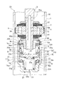
- FIG. 1 is a longitudinal sectional view of a shock absorber according to a first embodiment of the present invention.
- FIG. 2 is a partially enlarged longitudinal sectional view showing a modification of the shock absorber according to the first embodiment of the present invention.
- FIG. 3 is a partially enlarged longitudinal sectional view showing a modification of the shock absorber according to the first embodiment of the present invention.
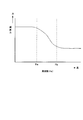
- FIG. 4 is a diagram illustrating a characteristic of the damping force with respect to the input frequency of the shock absorber.
- FIG. 5 is a partially enlarged longitudinal sectional view of the shock absorber according to the second embodiment of the present invention.
- FIG. 6 is a partially enlarged longitudinal sectional view of a shock absorber according to a third embodiment of the present invention.
- the shock absorber D1 includes a cylinder 1, a piston 2 that is slidably inserted into the cylinder 1, and divides the cylinder 1 into two extension side chambers R1 and a compression side chamber R2, and an extension side chamber R1.
- Damping passages 4 and 5 that communicate with the pressure side chamber R2, a housing 6 that forms the pressure chamber C, and a pressure chamber C that is slidably inserted into the housing 6 to extend the pressure side chamber 7 and the pressure side pressure chamber 8
- a free piston 9 that is divided into two, an extension side passage 10 that communicates the extension side chamber R1 and the extension side pressure chamber 7, a pressure side passage 11 that communicates the pressure side chamber R2 and the pressure side pressure chamber 8, and the free piston 9 in the housing 6
- a spring element 12 that exerts an urging force that suppresses the displacement of the free piston 9 from the neutral position and the free piston 9 with respect to the housing 6 from the neutral position to the extension pressure chamber side.
- the expansion side cushion 13 serves as a cushion that abuts on the free piston 9 and suppresses the displacement of the free piston 9 toward the expansion side pressure chamber, and a cushion fixing member that is fixed to the housing 6 and holds the expansion side cushion 13
- the extension side cushion fixing member 14 and the free piston 9 are displaced from the neutral position to the pressure side pressure chamber side by a predetermined displacement amount or more with respect to the housing 6, they abut against the free piston 9 and the pressure side pressure chamber side of the free piston 9.
- a pressure side cushion 15 as a cushion that suppresses displacement of the pressure side
- a pressure side cushion fixing member 16 as a cushion fixing member that is fixed to the housing 6 and holds the pressure side cushion 15.
- the shock absorber D1 further includes a piston rod 3 that is movably inserted into the cylinder 1.
- One end of the piston rod 3 is connected to the piston 2, and the upper end, which is the other end, is slidably supported by an annular rod guide (not shown) that seals the upper end of the cylinder 1.
- an annular rod guide (not shown) that seals the upper end of the cylinder 1.
- the lower end of the cylinder 1 is sealed by a bottom member (not shown).
- the extension side chamber R1, the pressure side chamber R2, and the pressure chamber C are filled with a liquid such as hydraulic oil.
- a sliding partition wall 17 that slidably contacts the inner periphery of the cylinder 1 to partition the pressure side chamber R2 and the gas chamber G is provided below the cylinder 1 in FIG.
- the liquid filled in the extension side chamber R1, the pressure side chamber R2, and the pressure chamber C may be water, an aqueous solution, or the like.
- the shock absorber D1 is a single rod type in which the piston rod 3 is inserted only into the extension side chamber R1.
- the volume of the piston rod 3 that goes in and out of the cylinder 1 as the shock absorber D1 expands and contracts is that the volume of the gas in the gas chamber G expands or contracts and the sliding partition 17 moves up and down in FIG. Compensated.
- a reservoir may be provided in the cylinder 1 or outside the cylinder 1 to compensate for the volume of the piston rod 3 that moves forward and backward in the cylinder 1.
- an outer cylinder that covers the outer periphery of the cylinder 1 may be provided to form a double cylinder type shock absorber that forms a reservoir between the cylinder 1 and the outer cylinder.
- a reservoir may be formed by a tank.
- a partition member that partitions between the pressure side chamber R2 and the reservoir in order to increase the pressure of the pressure side chamber R2 when the shock absorber D1 is contracted, and a liquid flow that is provided in the partition member and travels from the pressure side chamber R2 toward the reservoir.
- a base valve that provides resistance to.
- the shock absorber D may be a double rod type instead of a single rod type.
- the piston 2 is connected to one end 3a which is the lower end in FIG. 1 of the piston rod 3 which is movably inserted into the cylinder 1.
- the piston rod 3 protrudes outward through the inner periphery of an annular rod guide (not shown) fixed to the upper end of the cylinder 1 in FIG.
- the piston rod 3 and the rod guide are sealed with a seal member (not shown), and the cylinder 1 is kept in a liquid-tight state.
- the piston 2 includes damping passages 4 and 5 that communicate the extension side chamber R1 and the pressure side chamber R2.
- the lower end in FIG. 1 of the damping passage 4 is opened and closed by a leaf valve V1 stacked below the piston 2 in FIG.
- the upper end of the damping passage 5 in FIG. 1 is opened and closed by a leaf valve V2 stacked above the piston 2 in FIG.
- the leaf valve V1 is annular and is attached to the one end 3a of the piston rod 3 together with the piston 2.
- the leaf valve V1 bends as the liquid flows through the damping passage 4 from the expansion side chamber R1 toward the compression side chamber R2 during the extension stroke of the shock absorber D in which the piston 2 moves upward in FIG. It opens and gives resistance to the flow of the liquid, and closes the attenuation passage 4 against the reverse flow. That is, the attenuation passage 4 is a one-way passage that allows only the flow of liquid from the extension side chamber R1 toward the compression side chamber R2.
- the leaf valve V2 is annular and is attached to the one end 3a of the piston rod 3 together with the piston 2.
- the leaf valve V2 bends as the liquid flows through the damping passage 5 from the compression side chamber R2 toward the extension side chamber R1 during the contraction stroke of the shock absorber D in which the piston 2 moves downward in FIG. It opens and gives resistance to the flow of the liquid, and closes the attenuation passage 5 against the reverse flow. That is, the attenuation passage 5 is a one-way passage that allows only the flow from the compression side chamber R2 to the extension side chamber R1.
- the leaf valve V1 functions as an expansion side damping valve that provides resistance to the flow of liquid flowing through the attenuation passage 4 during the extension stroke, and the leaf valve V2 provides resistance to the flow of liquid that flows through the attenuation passage 5 during the contraction stroke. Functions as a compression side damping valve.
- each attenuation passage may be a one-way passage so that the liquid flows only during the extension stroke or during the contraction stroke.
- the damping passage may allow bidirectional flow and provide resistance to the flow of liquid passing therethrough.
- a damping valve that gives resistance to the flow of liquid passing through the damping passage, a poppet valve, an orifice, a choke, or the like may be used instead of the above-described leaf valve.
- the damping passages 4 and 5 may be provided in a portion other than the piston 2.
- the pressure chamber C is defined by a hollow housing 6 that is screwed into a screw portion 3b formed at the outer periphery of the tip end of the one end 3a of the piston rod 3.
- the housing 6 functions as a piston nut that fixes the piston 2 and the leaf valves V ⁇ b> 1 and V ⁇ b> 2 to one end 3 a of the piston rod 3.
- the pressure chamber C formed in the housing 6 is divided into an extension side pressure chamber 7 in the upper part in FIG. 1 and a pressure side pressure chamber 8 in the lower part in FIG. 1 by a free piston 9 slidably inserted into the pressure chamber C. Partitioned.
- the free piston 9 can be displaced in the vertical direction in FIG.
- the housing 6 includes a nut portion 20 screwed into a screw portion 3b formed at one end 3a of the piston rod 3, a cylindrical portion 22 suspended from the outer periphery of the nut portion 20, and an end portion of the cylindrical portion 22.
- a bottomed cylindrical housing cylinder 21 having a bottom 23 that closes the middle and lower ends.
- the housing 6 defines a pressure chamber C in the compression side chamber R2.
- the nut portion 20 has a screw cylinder 20a screwed into the screw portion 3b of the piston rod 3 and a flange 20b provided on the outer periphery of the screw cylinder 20a and protruding outward.
- the housing cylinder 21 is a bottomed cylinder, and is integrated with the nut portion 20 by crimping the upper end opening in FIG. 1 to the outer periphery of the flange 20b of the nut portion 20.
- the housing cylinder 21 is a bottomed cylinder having a cylinder part 22 that hangs down from the flange 20b and a bottom part 23 that closes an end of the cylinder part 22.
- the cylindrical portion 22 of the housing cylinder 21 includes an inner diameter large diameter portion 22a formed on the nut portion side where the free piston 9 is slidably contacted, an inner diameter small diameter portion 22b formed on the opposite side of the nut portion side, and an inner diameter large diameter portion 22a. And a step portion 22c formed between the inner diameter small diameter portion 22b.
- the nut portion 20 and the housing cylinder 21 may be integrated by a processing method such as welding or screwing other than caulking.
- the outer peripheral cross-sectional shape in at least a part of the cylindrical portion 22 of the housing cylinder 21 is formed in a shape other than a circle so that it can be gripped with a tool (not shown).
- the said shape is a shape corresponding to a tool, for example, the shape which notched a part, a hexagon, etc. Accordingly, the outer periphery of the cylindrical portion 22 is gripped with a tool, the housing 6 is rotated in the circumferential direction, a predetermined tightening torque is applied to the nut portion 20, and the nut portion 20 is screwed to the screw portion 3b. it can.
- the pressure chamber C and the pressure side chamber R2 are communicated with each other through an orifice hole 22d provided in the side portion of the cylindrical portion 22, and the pressure chamber C and the pressure side chamber R2 are communicated with each other through an orifice hole 23a provided in the bottom portion 23.
- the expansion side pressure chamber 7 communicates with the expansion side chamber R1 by an expansion side passage 10 that leads from the side of the piston rod 3 facing the expansion side chamber R1 to the end of the one end 3a.
- the extension side passage 10 is composed of a horizontal hole 10a that opens to the side facing the extension side chamber R1 of the piston rod 3, and a vertical hole 10b that opens to the end of one end 3a and communicates with the horizontal hole 10a.
- the free piston 9 inserted into the pressure chamber C includes a sliding contact cylinder 30 that is in sliding contact with the inner diameter large diameter portion 22a of the cylindrical portion 22 of the housing cylinder 21, and a mirror portion 31 that closes the lower end of the sliding contact cylinder 30. It has a bottomed cylindrical shape.
- the free piston 9 divides the inside of the housing 6 into an extension side pressure chamber 7 communicated with the extension side chamber R1 and a pressure side pressure chamber 8 communicated with the pressure side chamber R2.
- the free piston 9 has an annular recess 32 formed over the entire outer periphery of the sliding contact cylinder 30 and a communication hole 33 that allows the annular recess 32 to communicate with the pressure side pressure chamber 8.
- the pressure side chamber R2 communicates with the pressure side pressure chamber 8
- the annular recess 32 does not face the orifice hole 22d and is in sliding contact.
- the cylinder hole 30 closes the orifice hole 22d, the communication between the pressure side chamber R2 and the pressure side pressure chamber 8 through the orifice hole 22d is blocked.
- the orifice hole 22d provides resistance to the flow of liquid passing therethrough to cause a predetermined pressure loss, thereby generating a differential pressure between the pressure side chamber R2 and the pressure side pressure chamber 8.
- the orifice hole 23a formed in the bottom 23 of the housing cylinder 21 also functions as a constriction passage, giving resistance to the flow of the liquid passing therethrough and causing a predetermined pressure loss, so that the pressure side chamber R2 and the pressure side pressure chamber 8 A differential pressure is generated between them.
- the orifice hole 23a is not closed by the free piston 9 and is always open. That is, the pressure side pressure chamber 8 communicates with the pressure side chamber R2 via the orifice holes 22d and 23a when the orifice hole 22d is in communication, and the orifice hole 23a when the orifice hole 22d is in a shut-off state. Only through the pressure side chamber R2.
- the pressure side passage 11 is formed by the orifice holes 22 d and 23 a, the annular recess 32 and the communication hole 33.
- an extension side spring 34 which is a coil spring as the spring element 12 is interposed in a compressed state between the flange 20b of the nut part 20 and the mirror part 31 of the free piston 9 in the extension side pressure chamber 7. Is done.
- a compression side spring 35 which is a coil spring as the spring element 12, is interposed in a compressed state in the compression side pressure chamber 8 and between the bottom 23 and the mirror portion 31 of the free piston 9.
- the extension side spring 34 and the compression side spring 35 exert an urging force that suppresses the displacement of the free piston 9 relative to the housing 6.
- the free piston 9 is sandwiched from above and below by the extension side spring 34 and the pressure side spring 35 and is positioned at a predetermined neutral position in the pressure chamber C.
- the neutral position does not indicate the center of the pressure chamber C in the axial direction, but indicates the position where the free piston 9 is positioned by the spring element 12.
- the spring element 12 can exhibit urging
- the free piston 9 may be elastically supported using an elastic body such as a disc spring.
- a single spring element may be used so that one end of the spring element is connected to the free piston 9 and the other end is fixed to the nut portion 20 or the bottom portion 23.
- the extension side spring 34 is loosely fitted on the inner periphery of the sliding contact cylinder 30 of the free piston 9 and is positioned at a predetermined radial position.
- the compression side spring 35 is loosely fitted to a protrusion 31a formed at the lower end of the mirror part 31 of the free piston 9 in FIG. 1, and is positioned at a predetermined radial position.
- the extension side spring 34 and the pressure side spring 35 are both centered by the free piston 9, and displacement of the free side piston 9 is prevented. Thereby, the extension side spring 34 and the compression side spring 35 can apply an urging force to the free piston 9 stably.
- the free piston 9 is elastically supported by the extension side spring 34 and the compression side spring 35 in the housing 6, and is neutral in the housing 6 when no force is applied other than the urging force of the extension side spring 34 and the compression side spring 35. Positioned in position. When the free piston 9 is in the neutral position, the pressure side pressure chamber 8 and the pressure side chamber R2 are always in communication with the annular recess 32 facing the orifice hole 22d. When the free piston 9 is displaced from the neutral position, the outer periphery of the sliding cylinder 30 of the free piston 9 completely overlaps the orifice hole 22d and closes the orifice hole 22d.
- the amount of displacement from the neutral position at which the free piston 9 begins to close the orifice hole 22d can be set arbitrarily. Further, the displacement amount of the free piston 9 starting to close the orifice hole 22d from the neutral position toward the extension side pressure chamber 7, which is the upper side in FIG. 1, and the lower side of the free piston 9 starting to close the orifice hole 22d in FIG. The displacement amount from the neutral position toward the pressure-side pressure chamber 8 may be set differently.
- the number of orifice holes 22d is not limited to two, but may be any other number.
- An annular recess 32 communicated with the pressure side chamber R ⁇ b> 2 may be provided on the inner periphery of the cylindrical portion 22, and an orifice hole communicating with the outer peripheral side of the free piston 9 and the pressure side pressure chamber 8 may be provided in the free piston 9.
- the expansion side cushion 13 is fixed to the housing 6 by the expansion side cushion fixing member 14, and the compression side cushion 15 is fixed by the compression side cushion fixing member 16.
- the extension side cushion 13 is an elastic body such as an annular rubber, and is laminated on the flange 20b of the nut portion 20 so as to face the upper end of the sliding cylinder 30 of the free piston 9 in FIG.
- the extension side cushion 13 includes an annular recess 13a on the outer periphery of the free piston side end which is the lower end in FIG.
- the stretch side cushion fixing member 14 is annular and is laminated on the flange 20b.
- the extension side cushion fixing member 14 is held by the bent open end of the cylindrical portion 22 together with the flange 20b. 6 is fixed.
- a thin bent portion 22e to be crimped is provided at the upper end in FIG. 1 of the inner diameter / large diameter portion 22a of the cylindrical portion 22.
- a second step portion 22f is provided on the inner periphery of the inner diameter large diameter portion 22a.
- the extension side cushion fixing member 14 is laminated on the second step portion 22f, and the flange 20b of the nut portion 20 is laminated on the upper side of the extension side cushion fixing member 14 in FIG. In this way, when the bent portion 22e is crimped from the outer peripheral side in a state where the extended side cushion fixing member 14 and the flange 20b are stacked on the second step portion 22f, the extended side cushion fixing member 14 and the nut portion 20 are formed. It is gripped and fixed to the housing 6 by the bent portion 22e and the second step portion 22f after deformation.
- a flange-shaped fixing portion 14a that protrudes toward the inner peripheral side is provided on the inner periphery of the free piston side end of the stretch-side cushion fixing member 14.
- the fixing portion 14 a is fitted into an annular recess 13 a provided in the extension side cushion 13 and fixes the extension side cushion 13 to the housing 6.
- the shape of the fixing portion 14a may be a shape other than the flange as long as the extending side cushion 13 can be fixed to the housing 6. Further, the shape of the fixing portion 14a does not necessarily need to be an annular ring in the circumferential direction, but if it is an annular shape, deformation to the inner circumferential side when the expansion side cushion 13 is compressed can be suppressed without difficulty. It is possible to prevent the durability of the stretch cushion 13 from being lowered.
- the extension side cushion fixing member 14 prevents the extension side cushion 13 from falling off the housing 6. Further, when the housing cylinder 21 is fixed by crimping to the flange 20b of the nut portion 20, the extension side cushion fixing member 14 is crimped together with the flange 20b and integrated with the housing cylinder 21, so that the extension side cushion fixing member Since the process of fixing 14 to the housing 6 is easy and the number of processing steps is reduced, the cost is low.
- the compression side cushion 15 is an elastic body such as an annular rubber, and is laminated on the step portion 22 c of the cylindrical portion 22 of the housing cylinder 21 and faces the outer periphery of the lower end of the free piston 9 in FIG.
- the compression side cushion 15 is provided with the flange part 15a which protrudes toward the inner periphery on the opposite side to the free piston of the inner periphery.
- the pressure-side cushion fixing member 16 is cylindrical, and a press-fit portion 16a is formed on the opposite side from the free piston from the intermediate portion.
- the compression side cushion fixing member 16 is integrated with the housing 6 by press-fitting the press-fitting portion 16 a into the inner periphery of the inner diameter small-diameter portion 22 b of the housing cylinder 21.
- An annular mounting recess 22g is formed on the inner periphery of the upper end in FIG. 1 of the inner diameter small diameter portion 22b, and the press-fit portion 16a is press-fitted into the mounting recess 22g.
- the press-fit portion 16a does not protrude to the inner peripheral side from the inner diameter small-diameter portion 22b, and interference between the press-fit portion 16a and the pressure-side spring 35 is prevented. If the interference with the compression side spring 35 can be prevented, the mounting recess 22g need not be formed in the cylindrical portion 22.
- the compression side cushion fixing member 16 is also cylindrical on the free piston side from the press fitting portion 16a, and includes a flange-like fixing portion 16b whose outer diameter is increased toward the compression side cushion side. By hooking the fixing portion 16 b on the flange portion 15 a of the compression side cushion 15, the compression side cushion 15 is prevented from falling off the housing 6.
- the compression side cushion 15 is fixed to the housing 6 by fitting the compression side cushion fixing member 16 to the inner periphery of the compression side cushion 15.
- the cylindrical portion 22 and the compression side cushion fixing member 16 regulate the deformation of the compression side cushion 15 toward the inner peripheral side and the deformation toward the outer peripheral side. Deterioration of the compression side cushion 15 can be suppressed.
- the compression side cushion fixing member 16 is press-fitted into the small inner diameter portion 22b that is not the sliding contact surface of the free piston 9, so that the large inner diameter portion 22a that is the sliding surface of the free piston 9 is not damaged, and the compression side cushion is not damaged.
- the amount of displacement from the neutral position of the free piston 9 when the expansion side cushion 13 starts to abut the sliding contact cylinder 30 of the free piston 9 and the free piston when the compression side cushion 15 begins to abut the lower end of the free piston 9 can be arbitrarily set, and may be the same value or different values. Since the extension side cushion 13 and the compression side cushion 15 are installed in the housing 6 and abut against the free piston 9, the installation location with respect to the housing 6 can be appropriately changed according to the shape of the housing 6 and the free piston 9. is there.
- fixed part 16b does not necessarily need to be a cylindrical shape without a cut
- the fixing portion 16b is cylindrical, deformation to the inner peripheral side when the compression side cushion 15 is compressed can be suppressed without difficulty, and a decrease in durability of the compression side cushion 15 can be prevented.
- FIG. 2 is a partially enlarged longitudinal sectional view showing a modification of the shock absorber D1.
- the compression side cushion 15 is formed so that the cross-sectional shape of the free piston side end is a tapered shape. Thereby, since the contact area of the compression side cushion 15 and the free piston 9 becomes small, the contact sound produced when the compression side cushion 15 and the free piston 9 contact can be reduced.
- the pressure side cushion 15 is provided with a tapered surface whose inner diameter becomes smaller toward the opposite side of the free piston 9, A taper portion whose outer diameter increases toward the free piston side end may be provided on the outer periphery of the fixing member 16 on the free piston side.
- the taper part of the compression side cushion fixing member 16 is fitted to the taper surface of the compression side cushion 15, so that the compression side cushion 15 can be prevented from falling off the housing 6.
- the fixing portion 16b does not necessarily have an annular shape that is not continuous in the circumferential direction, but if it is an annular shape, deformation of the compression side cushion 15 toward the inner peripheral side can be easily suppressed when the compression side cushion 15 is compressed. Therefore, it is possible to prevent the durability of the compression side cushion 15 from being lowered.
- FIG. 3 is a partially enlarged longitudinal sectional view showing a modification of the shock absorber D1.
- the compression side cushion fixing member 16 is screwed and fixed instead of being press-fitted into the inner periphery of the inner diameter small diameter portion 22b.
- a screw portion 16d is provided on the outer periphery of the compression side cushion fixing member 16 instead of the press-fit portion 16a, and a screw portion 22h is provided on the inner periphery of the inner peripheral small diameter portion 22b.
- the housing 6 and the compression side cushion fixing member 16 are integrated by screwing the screw portion 16d and the screw portion 22h.
- the compression side cushion fixing member 16 hooks the fixing portion 16b on the flange portion 15a to fix the compression side cushion 15
- the shape of the fixing portion 16b may be a shape suitable for the shape of the compression side cushion 15.
- the fixing portion 16b does not necessarily have an annular shape that is not continuous in the circumferential direction, but if it is an annular shape, deformation of the compression side cushion 15 toward the inner peripheral side can be easily suppressed when the compression side cushion 15 is compressed. Therefore, it is possible to prevent the durability of the compression side cushion 15 from being lowered.
- the pressure chamber C is divided into the expansion side pressure chamber 7 and the pressure side pressure chamber 8 by the free piston 9, the expansion side chamber R1 and the pressure side chamber R2 are provided via the expansion side passage 10 and the pressure side passage 11. And are not directly communicated.
- the free piston 9 moves, the volume ratio between the expansion chamber R1 and the compression chamber R2 changes, and the liquid in the pressure chamber C enters and exits the expansion chamber R1 and the compression chamber R2 according to the amount of movement of the free piston 9. Accordingly, the pressure chamber C apparently behaves as if the expansion side chamber R1 and the pressure side chamber R2 are communicated with each other via the expansion side passage 10 and the pressure side passage 11.
- the shock absorber D1 can generate a high damping force for a low frequency vibration input and a low damping force for a high frequency vibration input.
- the shock absorber D1 can generate a high damping force in a scene where the frequency of the input vibration is low, such as when the vehicle is turning, and the frequency of the input vibration that causes the vehicle to pass through the unevenness of the road surface.
- a low damping force can be generated in a high scene. Therefore, the shock absorber D1 can improve the riding comfort in the vehicle.
- the differential pressure between the expansion side chamber R1 and the compression side chamber R2 during expansion and contraction of the shock absorber D1 is P
- the flow rate of the liquid flowing out from the expansion side chamber R1 is Q
- the differential pressure P and the attenuation passages 4 and 5 pass.
- the coefficient which is the relationship with the liquid flow rate Q1 is C1
- the pressure in the expansion side pressure chamber 7 is P1
- the coefficient that is the relationship with the flow rate Q2 is C2
- the pressure in the pressure side pressure chamber 8 is P2
- the coefficient that is the relationship between the pressure P2 and the flow rate Q2 of the liquid flowing out from the pressure side pressure chamber 8 into the pressure side chamber R2 is C3.
- A is the cross-sectional area that is the pressure receiving area of the free piston 9
- X is the displacement of the free piston 9 relative to the pressure chamber C
- the spring constant of the spring element 12 that is, the combined spring constant of the extension side spring 34 and the pressure side spring 35.
- Fb K / ⁇ 2 ⁇ ⁇ ⁇ A 2 ⁇ (C2 + C3) ⁇ .
- the transfer gain is substantially C1 in the region of F ⁇ Fa, and changes so as to gradually decrease from C1 to C1 ⁇ (C2 + C3) / (C1 + C2 + C3) in the region of Fa ⁇ F ⁇ Fb, and the region of F> Fb It becomes constant in. That is, in the frequency characteristic of the transfer function of the differential pressure P with respect to the flow rate Q, the transfer gain increases in the low frequency range, and the transfer gain decreases in the high frequency range.
- the shock absorber D1 generates a large damping force for low-frequency vibration input and exhibits a damping force reduction effect for high-frequency vibration input.
- a damping force can be generated.
- the shock absorber D1 can generate a high damping force in a scene where the input vibration frequency is low such as when the vehicle is turning, and also has a low attenuation in a scene where the input vibration frequency is high such that the vehicle travels on an uneven road surface. Force can be generated. Therefore, the shock absorber D1 can improve the riding comfort in the vehicle.
- the shock absorber D1 can be applied when high-frequency vibration is input. Is prevented from suddenly switching from a state where a low damping force is generated to a high damping force. Therefore, it is possible to prevent the passenger from feeling uncomfortable due to a shock caused by a change in the damping force.
- the flow passage area of the compression side passage 11 is reduced to gradually increase the flow passage resistance.
- the extension side passage The channel resistance of 10 may be increased.
- the shock absorber D1 When the shock absorber D1 has a vibration input in the direction of contraction with a large amplitude, and the free piston 9 is displaced from the neutral position to the expansion side pressure chamber side beyond a predetermined displacement, the free piston 9 impinges on the expansion side cushion 13. In addition, further displacement toward the extension side pressure chamber is suppressed. As a result, the displacement speed of the free piston 9 toward the expansion side pressure chamber is reduced, and direct collision between the free piston 9 and the housing 6 can be prevented, so that it is possible to prevent the occurrence of hitting sound.
- the shock absorber D1 When the shock absorber D1 has a vibration input in the extending direction with a large amplitude, and the free piston 9 is displaced from the neutral position to the pressure side pressure chamber side exceeding a predetermined displacement, the free piston 9 collides with the pressure side cushion 15. Thus, further displacement toward the pressure side pressure chamber is suppressed. As a result, the displacement speed of the free piston 9 toward the pressure side pressure chamber is reduced, and direct collision between the free piston 9 and the housing 6 can be prevented, so that it is possible to prevent the occurrence of hitting sound.
- the shock absorber D1 by providing the extension side cushion 13 and the compression side cushion 15, it is possible to prevent the generation of a hitting sound and to prevent the vehicle occupant from being uncomfortable due to the hitting sound. Therefore, riding comfort in the vehicle can be improved.
- the shock absorber D1 includes an extension side cushion fixing member 14 that fixes the extension side cushion 13 to the housing 6 and a compression side cushion fixing member 16 that fixes the compression side cushion 15 to the housing 6.
- shock absorber D2 in the second embodiment will be described with reference to FIG.
- the expansion side cushion 41, the expansion side cushion fixing member 42, the compression side cushion 43, and the compression side cushion fixing member 44 are different from the shock absorber D1 of the first embodiment, and other members are the same as the members of the shock absorber D1. is there. Therefore, the same members are denoted by the same reference numerals, and detailed description thereof is omitted.
- the extending side cushion 41 is an elastic body such as an annular rubber, and is laminated on the flange 20b of the nut portion 20 so as to face the upper end of the sliding cylinder 30 of the free piston 9 in FIG.
- the sliding cylinder 30 of the free piston 9 collides with the expansion side cushion 41, The upward displacement of the free piston 9 in FIG. 5 is suppressed.
- the extension side cushion 41 includes an annular recess 41a on the inner periphery of the free piston side end which is the lower end in FIG.
- the stretch side cushion fixing member 42 is annular and laminated on the flange 20b.
- the extension side cushion fixing member 42 rises downward from the outer periphery of the seat part 42a in FIG. 5 to the inner periphery of the extension side cushion 41 from the outer periphery of the seat part 42a.
- the fixed portion 42b includes a flange 42c that protrudes to the outer periphery.
- the extension side cushion 41 is fixed to the housing 6 by fitting the flange 42c into the annular recess 41a.
- the shape of the portion that fits into the annular recess 41 a of the fixing portion 42 b may be a shape other than the flange 42 c as long as the extension-side cushion 41 can be fixed to the housing 6.
- extension side cushion fixing member 42 By providing the extension side cushion fixing member 42, the extension side cushion 41 is prevented from falling off the housing 6. Further, since the extension side cushion fixing member 42 is clamped between the extension side spring 34 and the flange 20b of the nut portion 20 and fixed to the housing 6, the assembly process of the extension side cushion fixing member 42 to the housing 6 is performed. Can be facilitated, the number of processing steps can be reduced, and the cost can be reduced.
- the compression side cushion 43 is an elastic body such as an annular rubber, and is stacked on the step portion 22c of the cylindrical portion 22 of the housing cylinder 21 and faces the outer periphery of the lower end of the free piston 9 in FIG.
- the pressure side cushion 43 is provided with the annular recessed part 43a in the outer periphery of the free piston side end.
- the pressure-side cushion fixing member 44 includes an annular press-fit portion 44a and a flange-shaped fixing portion 44b that protrudes inward from the inner periphery of the free piston side end of the press-fit portion 44a.
- the compression side cushion fixing member 44 is integrated with the housing 6 by press-fitting the press-fit portion 44 a into the inner periphery of the inner diameter large-diameter portion 22 a of the housing cylinder 21. Since the inner diameter of the portion B where the lower press-fit portion 44a of the inner diameter large-diameter portion 22a in FIG.
- the compression side cushion fixing member 44 is not fixed to the inner diameter small diameter portion 22b, and therefore the mounting recess 22g as in the first embodiment is not provided.
- the compression side cushion fixing member 44 prevents the compression side cushion 15 from falling off the housing 6 by fitting the fixing portion 44b into an annular recess 43a provided on the outer periphery of the compression side cushion 43.
- the shape of the fixing portion 44b of the compression side cushion fixing member 44 may be a shape suitable for the shape of the compression side cushion 43, and does not necessarily have to be an annular shape that is not continuous in the circumferential direction. The deformation to the inner peripheral side when the pressure is compressed can be suppressed without difficulty, and the deterioration of the durability of the compression side cushion 43 can be prevented.
- the compression side cushion 43 is fixed to the housing 6 by fitting the compression side cushion fixing member 44 to the outer periphery of the compression side cushion 43. Thereby, when the compression side cushion 43 is compressed by the free piston 9, the deformation of the compression side cushion 43 toward the outer peripheral side is restricted. It is possible to prevent the compression side cushion 43 from being bitten.
- shock absorber D2 similarly to the shock absorber D1 of the first embodiment, by installing the extension side cushion 41 and the compression side cushion 43, it is possible to prevent the occurrence of a hitting sound and to make the vehicle occupant feel uncomfortable due to the hitting sound. It can prevent giving. Therefore, riding comfort in the vehicle can be improved.
- the shock absorber D2 includes an extension side cushion fixing member 42 that fixes the extension side cushion 41 to the housing 6 and a compression side cushion fixing member 44 that fixes the compression side cushion 43 to the housing 6.
- shock absorber D3 in the third embodiment will be described with reference to FIG.
- the pressure side cushion 51 and the pressure side cushion fixing member 52 are different from the shock absorber D1 of the first embodiment, and other members are the same as the members of the shock absorber D1. Therefore, the same members are denoted by the same reference numerals, and detailed description thereof is omitted.
- the compression side cushion fixing member 52 protrudes from the one end which is the free piston side end of the press-fitting portion 52a toward the outer peripheral side, and is pressed into the inner diameter small diameter portion 22b of the cylindrical portion 22 of the housing cylinder 21. And a flange-shaped fixing portion 52b stacked on the portion 22c.
- the compression side cushion fixing member 52 is fixed to the housing 6 by press-fitting the press-fitting portion 52a into the mounting recess 22g of the inner diameter small diameter portion 22b.
- the compression side cushion 51 is annular and is welded or fused to the fixed portion 52b.
- the compression side cushion 51 is fixed to the housing 6 via the compression side cushion fixing member 52.
- fixed part 52b is not restricted to a flange shape.
- the compression side cushion 52 is welded or fused to the fixed portion 52b, so that the compression side cushion 51 is prevented from falling off the housing 6.
- shock absorber D3 as in the shock absorber D1 of the first embodiment, by providing the extension side cushion 13 and the pressure side cushion 52, occurrence of a hitting sound can be prevented, and the vehicle occupant is not affected by the hitting sound. It can prevent giving a pleasant feeling. Therefore, riding comfort in the vehicle can be improved.
- the shock absorber D3 includes an extension side cushion fixing member 14 that fixes the extension side cushion 13 to the housing 6 and a compression side cushion fixing member 52 that fixes the compression side cushion 51 to the housing 6.
- the extension side cushion 13 and the pressure side cushion 51 can be reliably prevented from being displaced from or detached from the housing 6, and the position at which the free piston 9 contacts the extension side cushion 13 and the pressure side cushion 52 changes. Can be prevented. Therefore, the intended attenuation characteristic can be stably exhibited.
- the extension side cushions 13 and 41 and the compression side cushions 15, 43 and 51 are provided separately and independently in the housing 6. Therefore, the combination of the extended side cushions 13 and 41 and the extended side cushion fixing members 14 and 42 may be a combination other than the above as long as the extended side cushions 13 and 41 can be fixed. Similarly, the combination of the compression side cushions 15, 43, 51 and the compression side cushion fixing members 16, 44, 52 may be a combination other than the above as long as the compression side cushions 15, 43, 51 can be fixed. Moreover, you may provide only a stretch side cushion or only a compression side cushion as a cushion in a shock absorber.
Landscapes
- Engineering & Computer Science (AREA)
- General Engineering & Computer Science (AREA)
- Mechanical Engineering (AREA)
- Physics & Mathematics (AREA)
- Fluid Mechanics (AREA)
- Fluid-Damping Devices (AREA)
Abstract
Description


Claims (7)
- 緩衝装置であって、
シリンダと、
前記シリンダ内に摺動自在に挿入され前記シリンダ内を伸側室と圧側室とに区画するピストンと、
前記伸側室と前記圧側室とを連通する減衰通路と、
圧力室を形成するハウジングと、
前記圧力室内に摺動自在に挿入され前記圧力室を伸側圧力室と圧側圧力室とに区画するフリーピストンと、
前記伸側室と前記伸側圧力室とを連通する伸側通路と、
前記圧側室と前記圧側圧力室とを連通する圧側通路と、
前記フリーピストンを前記ハウジングに対して中立位置に位置決めるとともに前記フリーピストンの中立位置からの変位を抑制する附勢力を発揮するばね要素と、
前記フリーピストンが前記ハウジングに対して前記中立位置から所定の変位量以上変位すると前記フリーピストンに衝合して前記フリーピストンのそれ以上の変位を抑制するクッションと、
前記ハウジングに固定され前記クッションを保持するクッション固定部材と、
を備える緩衝装置。 - 請求項1に記載の緩衝装置であって、
一端が前記ピストンに連結されるピストンロッドをさらに備え、
前記ハウジングは、外周に鍔を有して前記ピストンを前記ピストンロッドに固定するナット部と、前記鍔から垂下される筒部と前記筒部の端部を閉塞する底部とを有する有底筒状のハウジング筒と、を有し、
前記筒部は、ナット部側であって前記フリーピストンが摺接する内径大径部と、前記ナット部とは反対側の内径小径部と、前記内径大径部と前記内径小径部との間に形成される段部と、を有し、
前記クッションは、環状であって前記段部に積層され、
前記クッション固定部材は、前記筒部に圧入される筒状の圧入部と、前記圧入部から伸びて前記クッションを前記ハウジングに固定する固定部と、を有する、
緩衝装置。 - 請求項2に記載の緩衝装置であって、
前記圧入部は、前記内径小径部に圧入され、
前記固定部は、前記クッションの内周に嵌合して前記クッションを前記ハウジングに固定する、
緩衝装置。 - 請求項2に記載の緩衝装置であって、
前記圧入部は、前記内径大径部に圧入され、
前記固定部は、前記クッションの外周に嵌合して前記クッションを前記ハウジングに固定する、
緩衝装置。 - 請求項2に記載の緩衝装置であって、
前記圧入部は、前記内径小径部に圧入され、
前記固定部は、前記圧入部の一端から外周側へ向けて突出して前記段部に積層されるフランジであり、
前記クッションは、環状であって前記固定部に溶着又は融着されて前記ハウジングに固定される、
緩衝装置。 - 請求項1に記載の緩衝装置であって、
一端が前記ピストンに連結されるピストンロッドをさらに備え、
前記ハウジングは、外周に鍔を有して前記ピストンを前記ピストンロッドに固定するナット部と、前記鍔から垂下される筒部と前記筒部の端部を閉塞する底部とを有する有底筒状のハウジング筒と、を有し、
前記筒部は、ナット部側であって前記フリーピストンが摺接する内径大径部と、前記ナット部とは反対側の内径小径部と、前記内径大径部と前記内径小径部との間に形成される段部と、を有し、
前記クッションは、環状であって前記鍔に積層され、
前記クッション固定部材は、環状であって前記筒部に把持されるとともに前記クッションの外周に嵌合して前記クッションを前記ハウジングに固定する固定部を有する、
緩衝装置。 - 請求項1に記載の緩衝装置であって、
一端が前記ピストンに連結されるピストンロッドをさらに備え、
前記ハウジングは、外周に鍔を有して前記ピストンを前記ピストンロッドに固定するナット部と、前記鍔から垂下される筒部と前記筒部の端部を閉塞する底部とを有する有底筒状のハウジング筒と、を有し、
前記筒部は、ナット部側であって前記フリーピストンが摺接する内径大径部と、前記ナット部とは反対側の内径小径部と、前記内径大径部と前記内径小径部との間に形成される段部と、を有し、
前記ばね要素は、前記伸側圧力室内に収容され前記フリーピストンと前記鍔との間に介装される伸側ばねと、前記圧側圧力室内に収容され前記フリーピストンと前記底部との間に介装される圧側ばねと、を有し、
前記クッションは、環状であって前記鍔に積層され、
前記クッション固定部材は、環状であって前記鍔と前記伸側ばねとの間に介装される座部と、前記座部の外周から立ち上がって前記クッションの内周に嵌合して前記クッションを前記ハウジングに固定する固定部と、を有する、
緩衝装置。
Priority Applications (3)
| Application Number | Priority Date | Filing Date | Title |
|---|---|---|---|
| DE112014000554.1T DE112014000554B4 (de) | 2013-01-25 | 2014-01-21 | Stoßdämpfer |
| US14/759,943 US9644703B2 (en) | 2013-01-25 | 2014-01-21 | Shock absorber |
| CN201480005744.0A CN104937304B (zh) | 2013-01-25 | 2014-01-21 | 缓冲装置 |
Applications Claiming Priority (2)
| Application Number | Priority Date | Filing Date | Title |
|---|---|---|---|
| JP2013-012516 | 2013-01-25 | ||
| JP2013012516A JP6027451B2 (ja) | 2013-01-25 | 2013-01-25 | 緩衝装置 |
Publications (1)
| Publication Number | Publication Date |
|---|---|
| WO2014115698A1 true WO2014115698A1 (ja) | 2014-07-31 |
Family
ID=51227489
Family Applications (1)
| Application Number | Title | Priority Date | Filing Date |
|---|---|---|---|
| PCT/JP2014/051048 Ceased WO2014115698A1 (ja) | 2013-01-25 | 2014-01-21 | 緩衝装置 |
Country Status (5)
| Country | Link |
|---|---|
| US (1) | US9644703B2 (ja) |
| JP (1) | JP6027451B2 (ja) |
| CN (1) | CN104937304B (ja) |
| DE (1) | DE112014000554B4 (ja) |
| WO (1) | WO2014115698A1 (ja) |
Cited By (2)
| Publication number | Priority date | Publication date | Assignee | Title |
|---|---|---|---|---|
| US20190195308A1 (en) * | 2016-09-08 | 2019-06-27 | Zf Friedrichshafen Ag | Frequency-Dependent Damping Valve Arrangement |
| WO2023233763A1 (ja) * | 2022-05-30 | 2023-12-07 | 日立Astemo株式会社 | 緩衝器 |
Families Citing this family (12)
| Publication number | Priority date | Publication date | Assignee | Title |
|---|---|---|---|---|
| JP5822359B2 (ja) * | 2013-03-27 | 2015-11-24 | Kyb株式会社 | 緩衝装置 |
| JP5970569B2 (ja) * | 2015-02-04 | 2016-08-17 | 日立オートモティブシステムズ株式会社 | 緩衝器 |
| BE1023716B1 (nl) * | 2016-01-03 | 2017-06-26 | Shi Yan | Frequentie afhankelijke schokdemper |
| JP6709099B2 (ja) * | 2016-04-06 | 2020-06-10 | Kyb株式会社 | 緩衝器 |
| DE102017207605A1 (de) * | 2017-05-05 | 2018-11-08 | Zf Friedrichshafen Ag | Dämpfventil für einen Schwingungsdämpfer |
| US10663027B2 (en) * | 2018-03-23 | 2020-05-26 | Tenneco Automotive Operating Company Inc. | Damper with valve preload limiter |
| US10570983B2 (en) | 2018-03-23 | 2020-02-25 | Tenneco Automotive Operating Company Inc. | Damper with floating piston bleed channel |
| DE102019210816A1 (de) * | 2019-07-22 | 2021-01-28 | Zf Friedrichshafen Ag | Dämpfventil mit frequenzabhängiger Dämpfkraft |
| CN111306137B (zh) * | 2020-03-05 | 2024-05-10 | 浙江中德自控科技股份有限公司 | 一种弹簧缓冲式气动执行机构 |
| DE102020130940A1 (de) * | 2020-11-23 | 2022-05-25 | Vb-Techniek B.V. | Hydraulischer Stoßdämpfer |
| ES3036444T3 (en) * | 2021-03-30 | 2025-09-18 | Zhejiang Zh Ind Co Ltd | Bidirectional self-locking damper |
| DE112022004296T5 (de) * | 2021-09-08 | 2024-07-18 | Hitachi Astemo, Ltd. | Stoßdämpfer |
Citations (2)
| Publication number | Priority date | Publication date | Assignee | Title |
|---|---|---|---|---|
| JP2012052630A (ja) * | 2010-09-02 | 2012-03-15 | Kyb Co Ltd | 緩衝装置 |
| JP2012137168A (ja) * | 2010-12-28 | 2012-07-19 | Hitachi Automotive Systems Ltd | 緩衝器 |
Family Cites Families (17)
| Publication number | Priority date | Publication date | Assignee | Title |
|---|---|---|---|---|
| FR1360210A (fr) * | 1963-03-02 | 1964-05-08 | Rech Etudes Prod | Suspension pour véhicules |
| JPS52630A (en) | 1975-11-20 | 1977-01-06 | Tadahiro Yuuki | Fruit cultivation |
| JPS62184244A (ja) * | 1986-02-06 | 1987-08-12 | Nhk Spring Co Ltd | 車両用懸架装置 |
| JPH0739273B2 (ja) * | 1986-11-12 | 1995-05-01 | いすゞ自動車株式会社 | キヤブテイルト・サスペンシヨン装置 |
| JPH0267136U (ja) * | 1988-11-10 | 1990-05-21 | ||
| US20030178267A1 (en) * | 2002-03-20 | 2003-09-25 | Doyle James D. | Fluid separator for a shock absorber |
| DE10258815A1 (de) * | 2002-12-17 | 2004-07-15 | Zf Sachs Ag | Schwingungsdämpfer mit amplitudenabhängiger Dämpfkraft |
| DE102004014395B4 (de) * | 2003-04-16 | 2015-10-29 | Zf Friedrichshafen Ag | Schwingungsdämpfer mit einem kolbenstangenseitigen Bypasskanal |
| JP2005076712A (ja) * | 2003-08-29 | 2005-03-24 | Tokico Ltd | 油圧ダンパ |
| US6918473B2 (en) * | 2003-09-17 | 2005-07-19 | Tenneco Automotive Operating Company Inc. | Stroke dependent bypass |
| JP2006207649A (ja) * | 2005-01-26 | 2006-08-10 | Kayaba Ind Co Ltd | 単筒型油圧緩衝器 |
| JP4726049B2 (ja) * | 2005-06-06 | 2011-07-20 | カヤバ工業株式会社 | 緩衝装置 |
| JP4768648B2 (ja) | 2007-03-02 | 2011-09-07 | カヤバ工業株式会社 | 緩衝装置 |
| ATE554307T1 (de) * | 2008-05-28 | 2012-05-15 | Bwi Co Ltd Sa | HYDRAULISCHER STOßDÄMPFER MIT EINER ZUSÄTZLICHEN KAMMERANORDNUNG UND VERFAHREN ZUR EINSTELLUNG DER DÄMPFUNGSEIGENSCHAFT EINES DERARTIGEN STOßDÄMPFERS |
| DE102011012730B4 (de) | 2010-03-02 | 2021-04-29 | Hitachi Automotive Systems, Ltd. | Stoßdämpfer |
| US8746423B2 (en) * | 2010-03-02 | 2014-06-10 | Hitachi Automotive Systems, Ltd. | Shock absorber |
| KR101254233B1 (ko) * | 2011-05-31 | 2013-04-18 | 주식회사 만도 | 쇽업소버의 밸브 구조 |
-
2013
- 2013-01-25 JP JP2013012516A patent/JP6027451B2/ja active Active
-
2014
- 2014-01-21 DE DE112014000554.1T patent/DE112014000554B4/de active Active
- 2014-01-21 WO PCT/JP2014/051048 patent/WO2014115698A1/ja not_active Ceased
- 2014-01-21 CN CN201480005744.0A patent/CN104937304B/zh active Active
- 2014-01-21 US US14/759,943 patent/US9644703B2/en active Active
Patent Citations (2)
| Publication number | Priority date | Publication date | Assignee | Title |
|---|---|---|---|---|
| JP2012052630A (ja) * | 2010-09-02 | 2012-03-15 | Kyb Co Ltd | 緩衝装置 |
| JP2012137168A (ja) * | 2010-12-28 | 2012-07-19 | Hitachi Automotive Systems Ltd | 緩衝器 |
Cited By (4)
| Publication number | Priority date | Publication date | Assignee | Title |
|---|---|---|---|---|
| US20190195308A1 (en) * | 2016-09-08 | 2019-06-27 | Zf Friedrichshafen Ag | Frequency-Dependent Damping Valve Arrangement |
| WO2023233763A1 (ja) * | 2022-05-30 | 2023-12-07 | 日立Astemo株式会社 | 緩衝器 |
| JPWO2023233763A1 (ja) * | 2022-05-30 | 2023-12-07 | ||
| JP7679554B2 (ja) | 2022-05-30 | 2025-05-19 | Astemo株式会社 | 緩衝器 |
Also Published As
| Publication number | Publication date |
|---|---|
| DE112014000554T5 (de) | 2015-11-19 |
| CN104937304B (zh) | 2016-12-14 |
| JP6027451B2 (ja) | 2016-11-16 |
| CN104937304A (zh) | 2015-09-23 |
| DE112014000554B4 (de) | 2022-09-01 |
| US9644703B2 (en) | 2017-05-09 |
| JP2014145374A (ja) | 2014-08-14 |
| US20150354660A1 (en) | 2015-12-10 |
Similar Documents
| Publication | Publication Date | Title |
|---|---|---|
| WO2014115698A1 (ja) | 緩衝装置 | |
| JP5822359B2 (ja) | 緩衝装置 | |
| JP4996952B2 (ja) | 緩衝装置 | |
| US20160263960A1 (en) | Shock absorber | |
| JP6462341B2 (ja) | 緩衝器 | |
| JP6709099B2 (ja) | 緩衝器 | |
| CN105387119A (zh) | 缓冲器 | |
| JP5603817B2 (ja) | 緩衝装置 | |
| JP2012052630A (ja) | 緩衝装置 | |
| WO2017175785A1 (ja) | 緩衝器及び緩衝器の製造方法 | |
| JP5809536B2 (ja) | 車両用緩衝器 | |
| JP5878840B2 (ja) | 緩衝装置 | |
| JP5878807B2 (ja) | 緩衝装置 | |
| JP2014031832A (ja) | 緩衝装置 | |
| JP6027462B2 (ja) | 緩衝装置 | |
| JP6182007B2 (ja) | 緩衝装置 | |
| JP6093599B2 (ja) | 緩衝装置 | |
| JP6082277B2 (ja) | 緩衝装置 | |
| JP2013204779A (ja) | 緩衝器 | |
| JP2013190011A (ja) | 緩衝装置 | |
| JP2014031831A (ja) | 緩衝装置 | |
| JP2014074444A (ja) | 緩衝装置 | |
| JP2013181643A (ja) | 車両用緩衝器 | |
| JP2013104496A (ja) | 車両用緩衝器 |
Legal Events
| Date | Code | Title | Description |
|---|---|---|---|
| 121 | Ep: the epo has been informed by wipo that ep was designated in this application |
Ref document number: 14743569 Country of ref document: EP Kind code of ref document: A1 |
|
| WWE | Wipo information: entry into national phase |
Ref document number: 14759943 Country of ref document: US |
|
| WWE | Wipo information: entry into national phase |
Ref document number: 112014000554 Country of ref document: DE Ref document number: 1120140005541 Country of ref document: DE |
|
| 122 | Ep: pct application non-entry in european phase |
Ref document number: 14743569 Country of ref document: EP Kind code of ref document: A1 |