WO2014112129A1 - 油圧ショベルおよび油圧ショベルの油圧シリンダのストローク計測方法 - Google Patents
油圧ショベルおよび油圧ショベルの油圧シリンダのストローク計測方法 Download PDFInfo
- Publication number
- WO2014112129A1 WO2014112129A1 PCT/JP2013/055095 JP2013055095W WO2014112129A1 WO 2014112129 A1 WO2014112129 A1 WO 2014112129A1 JP 2013055095 W JP2013055095 W JP 2013055095W WO 2014112129 A1 WO2014112129 A1 WO 2014112129A1
- Authority
- WO
- WIPO (PCT)
- Prior art keywords
- cylinder
- stroke length
- stroke
- hydraulic cylinder
- hydraulic
- Prior art date
- Legal status (The legal status is an assumption and is not a legal conclusion. Google has not performed a legal analysis and makes no representation as to the accuracy of the status listed.)
- Ceased
Links
Images






Classifications
-
- G—PHYSICS
- G01—MEASURING; TESTING
- G01B—MEASURING LENGTH, THICKNESS OR SIMILAR LINEAR DIMENSIONS; MEASURING ANGLES; MEASURING AREAS; MEASURING IRREGULARITIES OF SURFACES OR CONTOURS
- G01B21/00—Measuring arrangements or details thereof, where the measuring technique is not covered by the other groups of this subclass, unspecified or not relevant
- G01B21/22—Measuring arrangements or details thereof, where the measuring technique is not covered by the other groups of this subclass, unspecified or not relevant for measuring angles or tapers; for testing the alignment of axes
-
- E—FIXED CONSTRUCTIONS
- E02—HYDRAULIC ENGINEERING; FOUNDATIONS; SOIL SHIFTING
- E02F—DREDGING; SOIL-SHIFTING
- E02F3/00—Dredgers; Soil-shifting machines
- E02F3/04—Dredgers; Soil-shifting machines mechanically-driven
- E02F3/28—Dredgers; Soil-shifting machines mechanically-driven with digging tools mounted on a dipper- or bucket-arm, i.e. there is either one arm or a pair of arms, e.g. dippers, buckets
- E02F3/36—Component parts
- E02F3/42—Drives for dippers, buckets, dipper-arms or bucket-arms
- E02F3/425—Drive systems for dipper-arms, backhoes or the like
-
- E—FIXED CONSTRUCTIONS
- E02—HYDRAULIC ENGINEERING; FOUNDATIONS; SOIL SHIFTING
- E02F—DREDGING; SOIL-SHIFTING
- E02F3/00—Dredgers; Soil-shifting machines
- E02F3/04—Dredgers; Soil-shifting machines mechanically-driven
- E02F3/28—Dredgers; Soil-shifting machines mechanically-driven with digging tools mounted on a dipper- or bucket-arm, i.e. there is either one arm or a pair of arms, e.g. dippers, buckets
- E02F3/36—Component parts
- E02F3/42—Drives for dippers, buckets, dipper-arms or bucket-arms
- E02F3/43—Control of dipper or bucket position; Control of sequence of drive operations
- E02F3/435—Control of dipper or bucket position; Control of sequence of drive operations for dipper-arms, backhoes or the like
-
- E—FIXED CONSTRUCTIONS
- E02—HYDRAULIC ENGINEERING; FOUNDATIONS; SOIL SHIFTING
- E02F—DREDGING; SOIL-SHIFTING
- E02F9/00—Component parts of dredgers or soil-shifting machines, not restricted to one of the kinds covered by groups E02F3/00 - E02F7/00
- E02F9/20—Drives; Control devices
- E02F9/22—Hydraulic or pneumatic drives
- E02F9/2264—Arrangements or adaptations of elements for hydraulic drives
- E02F9/2271—Actuators and supports therefor and protection therefor
-
- E—FIXED CONSTRUCTIONS
- E02—HYDRAULIC ENGINEERING; FOUNDATIONS; SOIL SHIFTING
- E02F—DREDGING; SOIL-SHIFTING
- E02F9/00—Component parts of dredgers or soil-shifting machines, not restricted to one of the kinds covered by groups E02F3/00 - E02F7/00
- E02F9/26—Indicating devices
- E02F9/264—Sensors and their calibration for indicating the position of the work tool
-
- F—MECHANICAL ENGINEERING; LIGHTING; HEATING; WEAPONS; BLASTING
- F15—FLUID-PRESSURE ACTUATORS; HYDRAULICS OR PNEUMATICS IN GENERAL
- F15B—SYSTEMS ACTING BY MEANS OF FLUIDS IN GENERAL; FLUID-PRESSURE ACTUATORS, e.g. SERVOMOTORS; DETAILS OF FLUID-PRESSURE SYSTEMS, NOT OTHERWISE PROVIDED FOR
- F15B15/00—Fluid-actuated devices for displacing a member from one position to another; Gearing associated therewith
- F15B15/02—Mechanical layout characterised by the means for converting the movement of the fluid-actuated element into movement of the finally-operated member
- F15B15/04—Mechanical layout characterised by the means for converting the movement of the fluid-actuated element into movement of the finally-operated member with oscillating cylinder
-
- F—MECHANICAL ENGINEERING; LIGHTING; HEATING; WEAPONS; BLASTING
- F15—FLUID-PRESSURE ACTUATORS; HYDRAULICS OR PNEUMATICS IN GENERAL
- F15B—SYSTEMS ACTING BY MEANS OF FLUIDS IN GENERAL; FLUID-PRESSURE ACTUATORS, e.g. SERVOMOTORS; DETAILS OF FLUID-PRESSURE SYSTEMS, NOT OTHERWISE PROVIDED FOR
- F15B15/00—Fluid-actuated devices for displacing a member from one position to another; Gearing associated therewith
- F15B15/20—Other details, e.g. assembly with regulating devices
- F15B15/28—Means for indicating the position, e.g. end of stroke
-
- F—MECHANICAL ENGINEERING; LIGHTING; HEATING; WEAPONS; BLASTING
- F15—FLUID-PRESSURE ACTUATORS; HYDRAULICS OR PNEUMATICS IN GENERAL
- F15B—SYSTEMS ACTING BY MEANS OF FLUIDS IN GENERAL; FLUID-PRESSURE ACTUATORS, e.g. SERVOMOTORS; DETAILS OF FLUID-PRESSURE SYSTEMS, NOT OTHERWISE PROVIDED FOR
- F15B15/00—Fluid-actuated devices for displacing a member from one position to another; Gearing associated therewith
- F15B15/20—Other details, e.g. assembly with regulating devices
- F15B15/28—Means for indicating the position, e.g. end of stroke
- F15B15/2815—Position sensing, i.e. means for continuous measurement of position, e.g. LVDT
-
- F—MECHANICAL ENGINEERING; LIGHTING; HEATING; WEAPONS; BLASTING
- F15—FLUID-PRESSURE ACTUATORS; HYDRAULICS OR PNEUMATICS IN GENERAL
- F15B—SYSTEMS ACTING BY MEANS OF FLUIDS IN GENERAL; FLUID-PRESSURE ACTUATORS, e.g. SERVOMOTORS; DETAILS OF FLUID-PRESSURE SYSTEMS, NOT OTHERWISE PROVIDED FOR
- F15B15/00—Fluid-actuated devices for displacing a member from one position to another; Gearing associated therewith
- F15B15/20—Other details, e.g. assembly with regulating devices
- F15B15/28—Means for indicating the position, e.g. end of stroke
- F15B15/2815—Position sensing, i.e. means for continuous measurement of position, e.g. LVDT
- F15B15/2861—Position sensing, i.e. means for continuous measurement of position, e.g. LVDT using magnetic means
-
- G—PHYSICS
- G01—MEASURING; TESTING
- G01B—MEASURING LENGTH, THICKNESS OR SIMILAR LINEAR DIMENSIONS; MEASURING ANGLES; MEASURING AREAS; MEASURING IRREGULARITIES OF SURFACES OR CONTOURS
- G01B7/00—Measuring arrangements characterised by the use of electric or magnetic techniques
-
- G—PHYSICS
- G01—MEASURING; TESTING
- G01B—MEASURING LENGTH, THICKNESS OR SIMILAR LINEAR DIMENSIONS; MEASURING ANGLES; MEASURING AREAS; MEASURING IRREGULARITIES OF SURFACES OR CONTOURS
- G01B7/00—Measuring arrangements characterised by the use of electric or magnetic techniques
- G01B7/30—Measuring arrangements characterised by the use of electric or magnetic techniques for measuring angles or tapers; for testing the alignment of axes
-
- G—PHYSICS
- G01—MEASURING; TESTING
- G01D—MEASURING NOT SPECIALLY ADAPTED FOR A SPECIFIC VARIABLE; ARRANGEMENTS FOR MEASURING TWO OR MORE VARIABLES NOT COVERED IN A SINGLE OTHER SUBCLASS; TARIFF METERING APPARATUS; MEASURING OR TESTING NOT OTHERWISE PROVIDED FOR
- G01D5/00—Mechanical means for transferring the output of a sensing member; Means for converting the output of a sensing member to another variable where the form or nature of the sensing member does not constrain the means for converting; Transducers not specially adapted for a specific variable
- G01D5/12—Mechanical means for transferring the output of a sensing member; Means for converting the output of a sensing member to another variable where the form or nature of the sensing member does not constrain the means for converting; Transducers not specially adapted for a specific variable using electric or magnetic means
- G01D5/244—Mechanical means for transferring the output of a sensing member; Means for converting the output of a sensing member to another variable where the form or nature of the sensing member does not constrain the means for converting; Transducers not specially adapted for a specific variable using electric or magnetic means influencing characteristics of pulses or pulse trains; generating pulses or pulse trains
-
- G—PHYSICS
- G01—MEASURING; TESTING
- G01D—MEASURING NOT SPECIALLY ADAPTED FOR A SPECIFIC VARIABLE; ARRANGEMENTS FOR MEASURING TWO OR MORE VARIABLES NOT COVERED IN A SINGLE OTHER SUBCLASS; TARIFF METERING APPARATUS; MEASURING OR TESTING NOT OTHERWISE PROVIDED FOR
- G01D5/00—Mechanical means for transferring the output of a sensing member; Means for converting the output of a sensing member to another variable where the form or nature of the sensing member does not constrain the means for converting; Transducers not specially adapted for a specific variable
- G01D5/26—Mechanical means for transferring the output of a sensing member; Means for converting the output of a sensing member to another variable where the form or nature of the sensing member does not constrain the means for converting; Transducers not specially adapted for a specific variable characterised by optical transfer means, i.e. using infrared, visible, or ultraviolet light
- G01D5/264—Mechanical constructional elements therefor ; Mechanical adjustment thereof
-
- G—PHYSICS
- G01—MEASURING; TESTING
- G01D—MEASURING NOT SPECIALLY ADAPTED FOR A SPECIFIC VARIABLE; ARRANGEMENTS FOR MEASURING TWO OR MORE VARIABLES NOT COVERED IN A SINGLE OTHER SUBCLASS; TARIFF METERING APPARATUS; MEASURING OR TESTING NOT OTHERWISE PROVIDED FOR
- G01D5/00—Mechanical means for transferring the output of a sensing member; Means for converting the output of a sensing member to another variable where the form or nature of the sensing member does not constrain the means for converting; Transducers not specially adapted for a specific variable
- G01D5/26—Mechanical means for transferring the output of a sensing member; Means for converting the output of a sensing member to another variable where the form or nature of the sensing member does not constrain the means for converting; Transducers not specially adapted for a specific variable characterised by optical transfer means, i.e. using infrared, visible, or ultraviolet light
- G01D5/32—Mechanical means for transferring the output of a sensing member; Means for converting the output of a sensing member to another variable where the form or nature of the sensing member does not constrain the means for converting; Transducers not specially adapted for a specific variable characterised by optical transfer means, i.e. using infrared, visible, or ultraviolet light with attenuation or whole or partial obturation of beams of light
- G01D5/34—Mechanical means for transferring the output of a sensing member; Means for converting the output of a sensing member to another variable where the form or nature of the sensing member does not constrain the means for converting; Transducers not specially adapted for a specific variable characterised by optical transfer means, i.e. using infrared, visible, or ultraviolet light with attenuation or whole or partial obturation of beams of light the beams of light being detected by photocells
-
- G—PHYSICS
- G01—MEASURING; TESTING
- G01M—TESTING STATIC OR DYNAMIC BALANCE OF MACHINES OR STRUCTURES; TESTING OF STRUCTURES OR APPARATUS, NOT OTHERWISE PROVIDED FOR
- G01M13/00—Testing of machine parts
-
- G—PHYSICS
- G01—MEASURING; TESTING
- G01M—TESTING STATIC OR DYNAMIC BALANCE OF MACHINES OR STRUCTURES; TESTING OF STRUCTURES OR APPARATUS, NOT OTHERWISE PROVIDED FOR
- G01M17/00—Testing of vehicles
-
- F—MECHANICAL ENGINEERING; LIGHTING; HEATING; WEAPONS; BLASTING
- F15—FLUID-PRESSURE ACTUATORS; HYDRAULICS OR PNEUMATICS IN GENERAL
- F15B—SYSTEMS ACTING BY MEANS OF FLUIDS IN GENERAL; FLUID-PRESSURE ACTUATORS, e.g. SERVOMOTORS; DETAILS OF FLUID-PRESSURE SYSTEMS, NOT OTHERWISE PROVIDED FOR
- F15B2211/00—Circuits for servomotor systems
- F15B2211/60—Circuit components or control therefor
- F15B2211/63—Electronic controllers
- F15B2211/6303—Electronic controllers using input signals
- F15B2211/6336—Electronic controllers using input signals representing a state of the output member, e.g. position, speed or acceleration
-
- F—MECHANICAL ENGINEERING; LIGHTING; HEATING; WEAPONS; BLASTING
- F15—FLUID-PRESSURE ACTUATORS; HYDRAULICS OR PNEUMATICS IN GENERAL
- F15B—SYSTEMS ACTING BY MEANS OF FLUIDS IN GENERAL; FLUID-PRESSURE ACTUATORS, e.g. SERVOMOTORS; DETAILS OF FLUID-PRESSURE SYSTEMS, NOT OTHERWISE PROVIDED FOR
- F15B2211/00—Circuits for servomotor systems
- F15B2211/60—Circuit components or control therefor
- F15B2211/665—Methods of control using electronic components
- F15B2211/6656—Closed loop control, i.e. control using feedback
-
- F—MECHANICAL ENGINEERING; LIGHTING; HEATING; WEAPONS; BLASTING
- F15—FLUID-PRESSURE ACTUATORS; HYDRAULICS OR PNEUMATICS IN GENERAL
- F15B—SYSTEMS ACTING BY MEANS OF FLUIDS IN GENERAL; FLUID-PRESSURE ACTUATORS, e.g. SERVOMOTORS; DETAILS OF FLUID-PRESSURE SYSTEMS, NOT OTHERWISE PROVIDED FOR
- F15B2211/00—Circuits for servomotor systems
- F15B2211/70—Output members, e.g. hydraulic motors or cylinders or control therefor
- F15B2211/765—Control of position or angle of the output member
- F15B2211/7656—Control of position or angle of the output member with continuous position control
Definitions
- the present invention relates to a hydraulic excavator and a stroke measuring method of a hydraulic cylinder of the hydraulic excavator.
- a hydraulic excavator which is one of the work machines, has a traveling body, an upper revolving body that can swivel on the traveling body, and a work machine on the upper revolving body.
- the work machine includes a boom that is pivotally supported at one end on the base, an arm that is pivotally supported at the other end of the boom, and an attachment that is pivotally supported at the other end of the arm.
- the boom, arm, and attachment are driven by a hydraulic cylinder. In order to detect the position / posture of the work implement, the stroke of the hydraulic cylinder is measured.
- Patent Document 1 discloses a hydraulic excavator including a position sensor that detects a piston stroke position of a hydraulic cylinder that drives a working machine by rotation of a rotating roller on a cylinder rod. Yes. Since a minute slip occurs between the rotating roller and the cylinder rod, an error occurs between the stroke position obtained from the detection result of the position sensor and the actual stroke position. Therefore, a magnetic force sensor as a reset sensor is provided at the reference position on the outer surface of the cylinder tube of the hydraulic cylinder in order to calibrate the stroke position obtained from the detection result of the position sensor at the reference position. The stroke position detected by the position sensor every time the piston passes the reference position during work is calibrated, and accurate position measurement is possible.
- the magnetic force sensor described in the above publication detects the magnetic force (magnetic flux density) through the magnetic force lines generated by the magnet provided on the piston connected to the cylinder rod, and the electrical signal corresponding to the magnetic force (magnetic flux density). (Voltage) is output.
- this magnetic force sensor detects the stroke position at the peak of the voltage, the peak position of the voltage may not be detected accurately if the moving speed of the cylinder rod is high. In this case, since the stroke position obtained from the detection result of the position sensor cannot be accurately calibrated at the reference position, there is a problem that the shift in the stroke length cannot be corrected accurately.
- the hydraulic oil that operates the hydraulic cylinder that drives the work machine often has an oil temperature of nearly 100 ° C. during work.
- the reset sensor is attached to the cylinder tube, the sensor attachment position itself fluctuates due to expansion of the cylinder tube due to the oil temperature, causing measurement errors. From the viewpoint of avoiding the influence of expansion, it is desirable that the reset sensor be attached at or near the contraction side stroke end of the piston.
- the present invention has been made in view of the above problems, and an object of the present invention is to provide a hydraulic excavator capable of accurately measuring the stroke length of a hydraulic cylinder that drives a work machine, and a hydraulic cylinder stroke measuring method for the hydraulic excavator. Is to provide.
- the hydraulic excavator of the present invention includes a base part, a movable part, a hydraulic cylinder, a position sensor, a rotary encoder, and a control part.
- the base portion is composed of either a vehicle main body or a boom.
- the movable part is supported so as to be rotatable with respect to the base part.
- the hydraulic cylinder rotatably supports the movable part with respect to the base part.
- the position sensor is attached to the hydraulic cylinder and measures the stroke length of the hydraulic cylinder.
- the rotary encoder is mounted across the base portion and the movable portion, and includes a light emitting portion, a light receiving portion that can receive light emitted from the light emitting portion, and a plurality of transmission portions that transmit light emitted from the light emitting portion to the light receiving portion. And a disk portion that rotates in synchronization with the rotation of the movable portion with respect to the base portion.
- the light receiving unit outputs a pulse signal generated according to the rotation angle of the disk unit and associated with the rotation angle of the movable unit and the rotation angle of the disk unit based on the light emitted through the plurality of transmission units. .
- the controller measures the stroke length of the hydraulic cylinder by correcting the deviation of the stroke length measured by the position sensor based on the pulse signal output from the rotary encoder.
- the control unit corrects the deviation of the stroke length measured by the position sensor based on the pulse signal output from the rotary encoder. Since this pulse signal can be detected accurately, the stroke length deviation is corrected accurately by correcting the stroke length deviation measured by the position sensor based on the pulse signal output by the rotary encoder. The stroke length of the hydraulic cylinder can be measured.
- the rotary encoder outputs an A-phase pulse signal as a pulse signal, a B-phase pulse signal that is 90 ° out of phase with the A-phase pulse signal, and a stroke other than the stroke end of the hydraulic cylinder.
- a Z-phase pulse signal is output at the reference position. Since the hydraulic cylinder rarely reaches the stroke end of the hydraulic cylinder during work, the stroke length can be accurately measured during work by setting a position other than the stroke end of the hydraulic cylinder as the reference position.
- the hydraulic cylinder includes a cylinder tube and a cylinder rod that can move relative to the cylinder tube in the cylinder tube.
- the rotary encoder is located on one end outside the cylinder tube of the cylinder rod from the stroke end position on the cylinder rod extension side and on the other end side in the cylinder tube of the cylinder rod from the stroke end position on the contraction side of the cylinder rod.
- a Z-phase pulse signal is output at a reference position located within the range. By setting the reference position within the range, the stroke position can be reset at the reference position during work. Thereby, the shift
- the control unit stores a reference stroke length corresponding to an integer number of A-phase pulse signals after the Z-phase pulse signal is output.
- the control unit corrects the deviation of the stroke length measured by the position sensor in response to the integer number of A-phase pulse signals based on the reference stroke length.
- the reference stroke length corresponding to the same integer number of A-phase pulse signals and the stroke length measured by the position sensor can be compared to correct the stroke length deviation.
- an integer number of A-phase pulse signals are used, it is possible to suppress the influence of errors in the reference stroke length and the measured stroke length per one A-phase pulse signal.
- the first lever connected to the rotary encoder attached to the base portion, the second lever connected to the movable portion, and the first lever and the second lever are freely rotatable. And a ball joint connected to the. Thereby, propagation of load and vibration from the movable part to the rotary encoder attached to the base part can be reduced.
- the stroke measuring method of the hydraulic cylinder of the hydraulic excavator of the present invention includes the following steps.
- the stroke length of a hydraulic cylinder that rotatably supports the movable part with respect to the base part formed of either the vehicle main body or the boom is measured.
- a signal associated with the rotation angle of the movable part relative to the base part is output.
- the stroke length of the hydraulic cylinder is measured by correcting the deviation of the stroke length measured based on the signal.
- the stroke length of the hydraulic cylinder can be measured by correcting the displacement of the stroke length measured based on the signal associated with the rotation angle of the movable portion with respect to the base portion.
- the above-described hydraulic cylinder stroke measuring method of the hydraulic excavator includes the following steps.
- the stroke length of the hydraulic cylinder is measured as a rotation amount by a rotation sensor.
- a plurality of transmission parts that transmit light emitted from the light emitting part to the light receiving part are arranged, and according to the rotation angle of the disk part that rotates in synchronization with the rotation of the movable part relative to the base part
- a light-receiving part forms a pulse signal that is generated and has a rotation angle associated with the stroke length of the hydraulic cylinder based on light emission that has passed through a plurality of transmission parts, and a pulse signal is output by a rotary encoder.
- the control unit corrects the deviation of the stroke length measured by the rotation sensor based on the pulse signal output from the rotary encoder. Since this pulse signal can be accurately detected, the stroke length deviation is corrected by correcting the stroke length deviation measured by the position sensor based on the pulse signal output from the rotary encoder. The stroke length of the hydraulic cylinder can be measured.
- the hydraulic cylinder stroke measuring method of the hydraulic excavator of the present invention includes the following steps.
- the step of correcting by the control unit the displacement of the stroke length measured by the position sensor is corrected based on the pulse signal output from the rotary encoder when the hydraulic cylinder is stopped. Since the stroke length can be accurately measured by correcting the shift of the stroke length when the hydraulic cylinder is stopped, the stroke length can be corrected with high accuracy.
- the hydraulic cylinder stroke measuring method of the hydraulic excavator of the present invention includes the following steps.
- the step of correcting by the control unit the deviation of the stroke length measured by the position sensor corresponding to the integer number of pulse signals is corrected by the reference stroke length corresponding to the integer number of pulse signals from the reference position. For this reason, calibration at the same stroke position is always possible. As a result, the accuracy of calibration, that is, the accuracy of measurement is improved.
- the hydraulic cylinder stroke measuring method of the hydraulic excavator of the present invention includes the following steps.
- the movement direction of the cylinder rod of the hydraulic cylinder with respect to the cylinder tube in the measurement of the reference stroke length and the stroke length is the same. For this reason, the cylinder rod is moved with respect to the cylinder tube in the same moving direction, and the deviation of the stroke length is corrected. Therefore, the position sensor slips when the direction in which the cylinder rod moves with respect to the cylinder tube is different. The shift in stroke length can be eliminated.
- the stroke length of the hydraulic cylinder of the excavator working machine can be accurately measured.
- 1 is a perspective view schematically showing a configuration of a hydraulic excavator in an embodiment of the present invention.
- 1 is a diagram schematically showing a hydraulic circuit of a hydraulic excavator in an embodiment of the present invention. It is a figure which shows roughly the relationship between the hydraulic cylinder of the hydraulic shovel in one embodiment of this invention, a position sensor, a rotary encoder, and the measurement controller. It is a figure which shows roughly the relationship between the hydraulic cylinder of the hydraulic shovel and position sensor in one embodiment of this invention. It is a figure which shows schematically the position sensor of the hydraulic shovel in one embodiment of this invention.
- 1 is a perspective view schematically showing a configuration of a rotary encoder of a hydraulic excavator in an embodiment of the present invention.
- FIG. 1 It is sectional drawing which shows schematically the structure of the rotary encoder of the hydraulic shovel in one embodiment of this invention. It is a perspective view which shows roughly the relationship between the light emission part of the rotary encoder of the hydraulic shovel in one embodiment of this invention, a light-receiving part, and a disk part. It is a side view which shows roughly a mode that the boom of the hydraulic shovel in one embodiment of this invention raises / lowers. It is a figure which shows roughly the process by which the shift
- FIG. 7 is a schematic sectional view taken along line XIV-XIV in FIG. 6. It is a figure which shows schematically the magnetic force sensor attached to the bucket cylinder of the hydraulic shovel in one embodiment of this invention.
- the excavator 1 mainly includes a lower traveling body 2, an upper swing body 3, and a work machine 4.
- the lower traveling body 2 is configured to be capable of self-running when a pair of left and right crawler belts 2a rotate.
- the upper turning body 3 is installed on the lower traveling body 2 so as to be turnable.
- the work machine 4 is pivotally supported on the front side of the upper swing body 3 so as to be raised and lowered.
- the work machine 4 includes a boom 4a, an arm 4b, a bucket 4c as an example of an attachment, a hydraulic cylinder (bucket cylinder 4d, arm cylinder 4e, boom cylinder 4f), and the like.
- the work vehicle main body is mainly composed of the lower traveling body 2 and the upper turning body 3 described above.
- the upper swing body 3 has a cab 5 on the front left side (front side of the vehicle) and an engine room 6 for accommodating the engine on the rear side (rear side of the vehicle) and a counterweight 7.
- a driver's seat 8 for an operator to sit on is disposed in the cab 5.
- An antenna 9 is installed on the upper surface of the upper swing body 3.
- the front, rear, left, and right sides of the vehicle are based on an operator who sits in the driver's seat 8 disposed in the cab 5.
- the rotary encoder 20 is attached to the boom 4a.
- the rotary encoder 20 is also attached to the vehicle body as will be described later.
- the rotation of the arm 4b with respect to the boom 4a is transmitted to the rotary encoder 20 attached to the boom 4a via a pivotal lever to the arm 4b, and the rotary encoder 20 outputs a pulse signal corresponding to the rotation angle.
- the rotation of the boom 4a with respect to the vehicle main body 1a is transmitted to the rotary encoder 20 attached to the vehicle main body 1a via a pivotal support lever on the boom 4a, and the rotary encoder 20 outputs a pulse signal corresponding to the rotation angle.
- FIG. 2 A hydraulic circuit of a hydraulic excavator will be described with reference to FIGS. 1 and 2.
- an electric signal is input from the electric operation lever device 101 to the control controller 30a, and a control electric signal is supplied from the control controller 30a to the control valve 102 for the hydraulic cylinder (boom cylinder) 4f.
- the configuration in which the boom cylinder 4f is driven is shown.
- the work machine 4 is provided with a boom 4a, an arm 4b, and a bucket 4c.
- the boom cylinder 4f, the arm cylinder 4e, and the bucket cylinder 4d corresponding to these are driven, the boom 4a, the arm 4b, and the bucket 4c are driven.
- Each is activated.
- a hydraulic cylinder is provided for each boom 4a, arm 4b, and bucket 4c.
- the boom cylinder 4f is shown and the others are not shown.
- the boom cylinder 4f is driven using, for example, a variable displacement hydraulic pump 103 as a drive source.
- the hydraulic pump 103 is driven by the engine 3a.
- the swash plate 103 a of the hydraulic pump 103 is driven by the servo mechanism 104.
- the servo mechanism 104 operates according to a control signal (electric signal) output from the control controller 30a, and the swash plate 103a of the hydraulic pump 103 is changed to a position corresponding to the control signal.
- the engine drive mechanism 105 of the engine 3a operates in accordance with a control signal (electric signal) output from the control controller 30a, and the engine 3a rotates at a rotational speed corresponding to the control signal.
- the discharge port of the hydraulic pump 103 communicates with the control valve 102 via the discharge oil passage 106.
- the control valve 102 communicates with the oil chambers 40B and 40H of the boom cylinder 4f via the oil passages 107 and 108.
- the hydraulic oil discharged from the hydraulic pump 103 is supplied to the control valve 102 through the discharge oil passage 106, and the hydraulic oil that has passed through the control valve 102 passes through the oil passage 107 or 108 to the oil chamber 40B of the boom cylinder 4f. Or it is supplied to the oil chamber 40H.
- the position sensor 10 is attached to the boom cylinder 4f.
- the position sensor 10 is a stroke sensor that measures the stroke of the piston.
- a rotary encoder 20 is attached to a portion that pivotally supports one end of the boom 4a of the vehicle body 1a. The rotary encoder 20 detects the rotation angle of the boom 4a and outputs a pulse signal according to the rotation angle.
- the position sensor 10 and the rotary encoder 20 are each connected to a measurement controller 30.
- the battery 109 is a power source that activates the measurement controller 30 and the control controller 30a.
- the measurement controller 30 is electrically connected to the battery 109.
- the control controller 30a is electrically connected to the battery 109 via the engine key switch 110.
- the battery 109 When the engine key switch 110 is turned on, the battery 109 is electrically connected to a starting motor (not shown) of the engine 3a to start the engine 3a, and the battery 109 is electrically connected to the control controller 30a.
- the controller 30a for control is activated.
- the engine key switch 110 When the engine key switch 110 is turned off, the electrical connection between the control controller 30a and the battery 109 is cut off, the engine 3a is stopped, and the control controller 30a is started and stopped.
- the switch state signal indicating the switch state (on / off) of the engine key switch 110 is input to the measurement controller 30.
- the switch state signal input to the measurement controller 30 is on, the measurement controller 30 is activated, and when the switch state signal is off, the measurement controller 30 is activated. .
- the operating lever device 101 includes, for example, an operating lever 101a provided in the cab 5, and a detection unit 101b that detects an operating signal indicating an operating direction and an operating amount of the operating lever 101a.
- the operation signal detected by the detection unit 101b is input to the control controller 30a.
- the control valve 102 is connected to the controller 30a for control via an electric signal line.
- an operation signal of the operation lever 101a is input to the control controller 30a, and a control signal for operating the control valve 102 is generated by the control controller 30a.
- the control signal is supplied from the control controller 30a to the control valve 102 via the electric signal line, and the valve position of the control valve 102 is changed.
- a position sensor 10 that detects the stroke amount of the hydraulic cylinder as a rotation amount is attached to each of the arm cylinder 4e and the boom cylinder 4f.
- a position sensor 10 and a magnetic force sensor 20a are attached to the bucket cylinder 4d.
- a rotary encoder 20 that outputs a pulse signal according to the amount of rotation (angle) of the arm 4b and the boom 4a is attached to a part that supports the boom 4a, the arm 4b of the vehicle main body 1a, and the pivot shaft of the boom 4a.
- the pulse signal is a rectangular wave.
- the position sensor 10, the rotary encoder 20, and the magnetic force sensor 20a are electrically connected to the measurement controller 30.
- the measurement controller 30 measures the stroke lengths of the bucket cylinder 4d, the arm cylinder 4e, and the boom cylinder 4f based on detection signals from the position sensor 10, the rotary encoder 20, and the magnetic force sensor 20a. Further, the measurement controller 30 calculates the position / posture of the bucket 4c based on the measured stroke of each cylinder.
- the position sensor 10 will be described with reference to FIGS. For convenience of explanation, the position sensor 10 attached to the boom cylinder 4f will be described, but the same position sensor 10 is also attached to the arm cylinder 4e.
- the boom cylinder 4f has a cylinder tube 4X and a cylinder rod 4Y that can move relative to the cylinder tube 4X in the cylinder tube 4X.
- a piston 4V is slidably provided on the cylinder tube 4X.
- a cylinder rod 4Y is attached to the piston 4V.
- the cylinder rod 4Y is slidably provided on the cylinder head 4W.
- a chamber defined by the cylinder head 4W, the piston 4V, and the cylinder inner wall constitutes a cylinder head side oil chamber 40H.
- An oil chamber opposite to the cylinder head side oil chamber 40H via the piston 4V constitutes a cylinder bottom side oil chamber 40B.
- the cylinder head 4W is provided with a seal member that seals the gap with the cylinder rod 4Y and prevents dust and the like from entering the cylinder head side oil chamber 40H.
- a case 14 that covers the position sensor 10 and accommodates the position sensor 10 inside is provided outside the cylinder head side oil chamber 204H and in close contact with the cylinder head 4W.
- the case 14 is fastened to the cylinder head 4W by a bolt or the like and fixed to the cylinder head 4W.
- the position sensor 10 includes a rotating roller 11, a rotation center shaft 12, and a rotation sensor unit 13.
- the surface of the rotating roller 11 is in contact with the surface of the cylinder rod 4Y and is rotatably provided according to the direct movement of the cylinder rod 4Y. That is, the linear motion of the cylinder rod 4Y is converted into rotational motion by the rotating roller 11.
- the rotation center shaft 12 is disposed so as to be orthogonal to the linear movement direction of the cylinder rod 4Y.
- the rotation sensor unit 13 is configured to detect the rotation amount (rotation angle) of the rotation roller 11.
- a signal indicating the rotation amount (rotation angle) of the rotation roller 11 detected by the rotation sensor unit 13 is sent to the measurement controller 30 via the electric signal line, and the cylinder rod of the boom cylinder 4f is measured by the measurement controller 30. It is converted to a 4Y position (stroke position).
- the rotation sensor unit 13 includes a magnet 13a and a Hall IC 13b.
- a magnet 13 a that is a detection medium is attached to the rotating roller 11 so as to rotate integrally with the rotating roller 11.
- the magnet 13 a rotates in accordance with the rotation of the rotating roller 11 around the rotation center axis 12.
- the magnet 13 a is configured such that the N pole and the S pole are alternately switched according to the rotation angle of the rotating roller 11.
- the magnet 13a is configured such that the magnetic force (magnetic flux density) detected by the Hall IC 13b periodically varies with one rotation of the rotating roller 11 as one cycle.
- the Hall IC 13b is a magnetic sensor that detects the magnetic force (magnetic flux density) generated by the magnet 13a as an electrical signal.
- the Hall IC 13b is provided at a position separated from the magnet 13a by a predetermined distance along the axial direction of the rotation center shaft 12.
- the electrical signal detected by the Hall IC 13b is sent to the measurement controller 30, and the electrical signal of the Hall IC 13b is converted into the rotation amount of the rotating roller 11, that is, the displacement amount of the cylinder rod 4Y of the boom cylinder 4f. Converted to (stroke length). Specifically, the amount of linear movement of the cylinder rod 4Y when the rotation roller 11 makes one rotation is calculated as 2 ⁇ d using the rotation radius d of the rotation roller 11.
- the number of rotations of the rotating roller 11 can be measured by counting the number of times one cycle of the electric signal (voltage) output from the Hall IC 13b is repeated. Based on the rotation angle of the rotation roller 11 and the rotation speed of the rotation roller 11, the displacement amount (stroke length) of the cylinder rod 4Y of the boom cylinder 4f is measured.
- the rotary encoder 20 will be described with reference to FIGS.
- the rotary encoder 20 connected to the vehicle main body 1a as a base portion and the boom 4a as a movable portion will be described.
- the boom 4a as the base portion and the arm 4b as the movable portion.
- a rotary encoder 20 is attached.
- the movable part is rotatably supported with respect to the base part.
- the hydraulic cylinder supports the movable part so as to be rotatable with respect to the base part.
- the rotary encoder 20 is attached to the vehicle main body 1a which is a base portion.
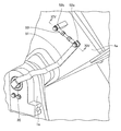
- the rotary encoder 20 is connected to the boom 4a, which is a movable part, via a first lever 51, first and second ball joints 52a and 52b, and a second lever 53. Since the rotary encoder 20 is not connected to the boom cylinder 4f, the rotary encoder 20 is not easily affected by an increase in the oil temperature during operation of the hydraulic oil.
- the first lever 51, the first and second ball joints 52a and 52b, and the second lever 53 will be described later.
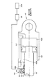
- the rotary encoder 20 includes a housing 21, a rotating shaft 22, bearings 23 and 24, a disk portion 25, a light emitting portion 26, and a light receiving portion 27. ing. Bearings 23 and 24 that rotatably support the rotary shaft 22, a disk portion 25, a light emitting portion 26, and a light receiving portion 27 are accommodated in the housing 1. One end of the rotating shaft 22 is supported by the bearings 23 and 24, and the other end is connected to the lever 51. A disk portion 25 is connected to the rotating shaft 22 in the housing 21 so as to rotate integrally with the rotating shaft 22, and a light emitting portion 26 and a light receiving portion 27 are disposed so as to sandwich the disk portion 25. .
- the light emitting unit 26 has a light emitting element that emits light to the light receiving unit 27.
- the light receiving unit 27 includes four light receiving elements 27 a that can receive light emitted from the light emitting unit 26.
- the four light receiving elements 27a have the same width W, and are arranged in an arc continuously in series.
- the light receiving element 27a converts the received light quantity into an electrical signal.
- a plurality of first transmission parts 25 a that transmit light emitted from the light emitting part 26 to the light receiving part 27 are arranged in the disk part 25.
- the first transmission part 25a is a substantially rectangular slit extending in the radial direction having a circumferential width of 2W, and is arranged in the vicinity of the outer periphery of the disk part 25 in an annular shape parallel to the outer periphery at an interval of 2W.
- a single transmission part 25b is arranged on the inner periphery of the ring formed by the first transmission part 25a.
- the transmission part 25b is a substantially rectangular slit extending in the radial direction.
- the disk part 25 is rotated by the first and second levers 51 and 53 in synchronization with the rotation of the boom 4a with respect to the vehicle body 1a.
- the four light receiving elements 27a each output an electrical signal according to the amount of light transmitted through the first and second transmission parts 25a and 25b by the rotation of the disk part 25.
- the light receiving unit 27 is the number of first transmission units 25a through which light passes through the electrical signals from the first and third, and the second and fourth light receiving elements 27a that are spaced apart from each other in series. Are respectively converted into pulse signals corresponding to the above and output to the measurement controller 30. The reason why the electrical signals from the two light receiving elements 27a are used to generate one pulse signal is to improve the robustness of the sensor against external light or the like.
- the light receiving portion 27 when the light receiving element 27a outputs an electric signal based on the light transmitted through the transmitting portion 25b, the light receiving portion 27 outputs a corresponding pulse signal. That is, the light receiving unit 27 outputs three pulse signals generated according to the rotation angle of the disk unit 25. Since the rotation angle of the disk portion 25 is the same as the rotation angle of the boom 4a, the pulse signal is output according to the rotation angle of the boom cylinder 4f.
- the rotary encoder 20 is an incremental type, and a Z-phase pulse signal, a B-phase pulse signal that is 90 ° out of phase with the A-phase, and Z generated once in one rotation of the disk portion 25.
- a phase pulse signal (reference pulse signal) can be output.
- the measurement controller 30 counts the number of pulses of the A-phase pulse signal. The count number is proportional to the amount of rotation of the boom cylinder 4f.
- the measurement controller 30 determines the rotation direction of the boom 4a from the difference in phase between the A phase and the B phase.
- the reference position of the boom 4a rotation is measured by the Z-phase pulse signal.
- the approximate center of the pivotable angle range of the boom 4a is set as the reference position.
- the setting reference position is stored in the measurement controller 30.
- the Z-phase pulse signal is output when the light transmitted through the transmission part 25 a corresponding to the Z-phase is blocked by the disk part 25. That is, the Z-phase pulse signal is detected when the pulse signal falls.
- the rotary encoder 20 outputs a Z-phase pulse signal at an approximately central angle of the boom 4a rotation area. That is, the rotary encoder 20 outputs a Z-phase pulse signal substantially at the center of the stroke range of the boom cylinder 4f.
- the set reference position of the encoder 20 is as described above, but any position other than the stroke end of the hydraulic cylinder may be used as the reference position. More specifically, the rotary encoder 20 has a stroke end position on the outer side of the cylinder tube 4X of the cylinder rod 4Y and a stroke end position on the contraction side of the cylinder rod 4Y.
- a Z-phase pulse signal may be output with the rotation angle of the boom 4a corresponding to the other end side in the cylinder tube 4X of the cylinder rod 4Y as a reference position.
- the case where the boom 4a moves up and down will be described as an example.
- the boom 4a moves up and down as the boom cylinder 4f expands and contracts.
- the boom cylinder 4f reaches the stroke end on the expansion side when the boom 4a rises to the maximum, and reaches the stroke end on the contraction side when the boom 4a descends to the bottom.
- the stroke length of the boom cylinder 4 f is measured by the position sensor 10 as the rotation amount of the rotary roller 11.
- a minute slip occurs between the rotating roller 11 (see FIG. 4) of the position sensor 10 and the cylinder rod 4Y, and the cylinder rod 4Y obtained from the detection result of the position sensor 10 due to this slip.
- the rotating roller 11 and the rotary encoder 20 are connected to a measurement controller 30, and the measurement controller 30 calibrates the stroke length measured by the position sensor 10 based on the pulse signal output from the rotary encoder 20.
- the measurement including the calibration of the stroke length will be described mainly with reference to FIG.
- the boom cylinder 4f extends.
- the stroke length of the boom cylinder 4 f is measured by the position sensor 10.
- the rotary encoder 20 as the boom 4a is raised, the boom 4a rotates with respect to the vehicle body 1a, so that the disk portion 25 rotates.
- the light receiving unit 27 receives light emitted from the light emitting unit 26 that has passed through the transmitting units 25 a and 25 b of the disk unit 25, so that a pulse signal corresponding to the rotation angle of the disk unit 25 is output from the light receiving unit 27.
- the The light receiving unit 27 outputs A-phase, B-phase, and Z-phase pulse signals, respectively.
- the Z-phase pulse signal is associated with a reference angle that is a predetermined rotation angle of the boom 4a, and is output when the boom 4a comes to the position of the reference angle.
- the measuring controller 30 stores the stroke length of the boom cylinder 4f when the boom 4a is in the posture of the boom 4a to which the rotary encoder 20 outputs a Z-phase pulse signal as the storage reference position P.
- the storage reference position P is calibrated at the time of initial calibration described later, and is stored as the calibration reference position P ′.
- the length L1 is a length detected by the position sensor 10.
- the measurement controller 30 stores a reference stroke length L2 for an A-phase pulse signal of a predetermined integer number of pulses calculated and stored by initial calibration described later.
- the measurement controller 30 calculates a difference L3 between the measurement stroke length L1 and the reference stroke length L2.
- the measurement controller 30 calibrates the measurement value of the position sensor 10 based on the difference L3 when it stops after detecting the Z-phase pulse signal and operating the boom cylinder 4f.
- the reference position P of the stroke of the boom cylinder 4f corresponding to the posture of the boom 4a to which the Z-phase pulse signal is output is stored in advance. In order to more accurately associate the stored reference position with the Z-phase pulse signal output, calibration is performed before work.
- the calibration mode is turned on with the arm 4b of the excavator 1 extended and the boom 4a raised to the highest position (initial position of the work implement) (S10).
- the cylinder rod 4Y of the boom cylinder 4f is located at the stroke end on the extension side.
- the cylinder rod of the arm cylinder 4e is positioned at the stroke end on the contraction side.
- the work machine is operated (S11), and the arm 4b is bent.
- the arm cylinder 4e shown in FIG. 3 is bent at a constant speed and a slower speed than during normal work.
- a Z-phase pulse signal is output at a rotation angle substantially in the middle of the movable rotation range of the arm 4b.
- the measurement controller 30 calculates the stroke of the arm cylinder 4e from the expansion side stroke end to the Z-phase pulse signal output by the output of the rotary encoder 20, and stores the stroke from the corresponding contraction side stroke end as the calibration reference position P ′. That is, the stroke calibration reference position P ′ is set by the number of pulses of the pulse signal corresponding to the rotation angle of the arm 4b (S12).
- the arm cylinder 4e continues to operate in a further extending direction. Every time the A-phase pulse signal is counted 10 times, the electrical signal of the position sensor 10 is stored in the measurement controller 30 and similarly, 15 times in total. Stroke lengths based on 15 electrical signals are respectively calculated, and an average value thereof is calculated. In this way, the average stroke length of the arm cylinder 4e in the calibration mode is detected (S13). As described above, the measurement controller 30 measures the stroke length corresponding to the A-phase pulse signal 10 times by the position sensor 10 and stores it as the reference stroke length L2.
- the work machine is operated (S11), and the boom 4a is lowered.
- the boom cylinder 4f shown in FIG. 10 is shortened at a constant speed and a slower speed than during normal work.
- a Z-phase pulse signal is output at a substantially intermediate rotation angle of the movable rotation range of the boom 4a.
- the measurement controller 30 measures the stroke of the boom cylinder 4f from the contraction side stroke end to the Z-phase pulse signal output by the position sensor 10, and stores the stroke as the calibration reference position L2. In this way, the calibration reference position, which is an initial value for calibration, is acquired (S12).
- the electrical signal of the position sensor 10 is stored in the measurement controller 30, and similarly, 15 times in total. Stroke lengths based on 15 electrical signals are respectively calculated, and an average value thereof is calculated. In this way, the average value of the stroke length of the boom cylinder 4f in the calibration mode is detected (S13).
- the measurement controller 30 measures the stroke length corresponding to the ten A-phase pulse signals from the rotary encoder 20 by the position sensor 10 and stores it as the reference stroke length L2. Thereafter, the calibration mode is turned off (S14).
- the stroke measurement during the normal operation is turned on (S20). Thereafter, the work machine is operated (S21). During operation, when the rotation angle of the arm cylinder 4e becomes the reference angle, a Z-phase pulse signal is output by the rotary encoder 20 (S22). When the arm 4b rotates further after passing through the reference angle (when the arm cylinder 4e extends further), every time the A-phase pulse signal is counted 10 times after the Z-phase pulse signal is output by the rotary encoder 20. The electrical signal of the position sensor 10 is stored in the measurement controller 30 and is similarly stored 15 times in total. Stroke lengths based on 15 electrical signals are respectively calculated, and an average value thereof is calculated. In this way, the average value of the stroke length per 10 pulse signals of the arm cylinder 4e is detected (S23).
- the work machine is operated (S11), and the boom 4a is lowered.
- the boom 4a shown in FIG. 10 is shortened at a speed higher than that during normal work.
- a Z-phase pulse signal is output by the rotary encoder 20 (S22).
- the position sensor 10 measures the stroke length after passing through the reference angle.
- the electrical signal of the position sensor 10 is stored in the measurement controller 30. Stored. Stroke lengths based on 15 electrical signals are respectively calculated, and an average value thereof is calculated. In this way, the average value of the stroke length per 10 pulse signals of the boom cylinder 4f in the normal mode is detected (S23).
- the average stroke length of the arm cylinder 4e in the calibration mode (reference stroke length L2) is compared with the average stroke length of the arm cylinder 4e in the normal mode (S24). Then, based on the average value of the stroke length of the arm cylinder 4e in the calibration mode, the average value of the stroke length of the arm cylinder 4e in the normal mode is corrected, thereby correcting the shift of the stroke length in the normal mode (S25). ).
- the correction of the stroke length deviation is performed in a state where the hydraulic cylinders (arm cylinder 4e, boom cylinder 4f) are stopped.
- the state in which the hydraulic cylinder is stopped is a state in which the movement of the work implement is stopped.
- the cylinder rod 4Y is moved relative to the cylinder tube 4X in the same direction as the cylinder rod 4Y is moved relative to the cylinder tube 4X, thereby correcting the stroke length deviation.
- the movement direction of the arm cylinder 4e and the boom cylinder 4f in the calibration mode and the movement direction of the arm cylinder 4e and the boom cylinder 4f in the normal mode are set in the same direction, and the shift in the stroke length is corrected.
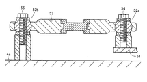
- the first lever 51 is for transmitting the rotation of the boom 4 a to the rotary encoder 20.
- the first lever 51 extends in a direction orthogonal to the rotation shaft 22 (see FIG. 7).
- One end of the first lever 51 is connected to the rotary shaft 22 of the rotary encoder 20 attached to the vehicle body 1a.
- the other end of the first lever 51 is rotatably connected to one end of the second lever 53 via the first ball joint 52a.
- the first ball joint 52 a is fixed to the first lever 51 with a bolt 54.
- the second lever 53 has one end connected to the first lever 51 via the first ball joint 52a, and the other end connected to the boom 4a via the second ball joint 52b.
- the second lever 53 extends along the boom 4a.
- the second ball joint 52b is rotatably attached to the second lever 53 and is attached to the boom 4a.
- the second ball joint 52b is fixed to the boom 4a with a bolt 55.
- the rotary shaft 22 of the rotary encoder 20 rotates the same as the rotation amount of the boom 4a with respect to the vehicle body 1a. Further, by connecting the rotary encoder 20 and the boom 4a not by one lever but by two levers connected by one ball joint as described above, propagation of load and vibration from the boom 4a to the encoder 20 is achieved. Can be reduced. As a result of reducing the load and vibration, the rotary encoder 20 can be prevented from being damaged and the measurement accuracy can be improved.
- a slight slip is unavoidable between the rotating roller 11 of the position sensor 10 and the cylinder rod 4Y.
- the slip of the cylinder rod 4Y obtained from the detection result of the position sensor 10 by this slip is unavoidable.
- An error occurs between the measurement position and the actual position of the cylinder rod 4Y.
- the bucket cylinder 4d does not require higher stroke length detection accuracy than the boom cylinder 4f and the arm cylinder 4e. For this reason, the magnetic force sensor 20a is attached to the bucket cylinder 4d as a reset sensor in order to reset the stroke position obtained from the detection result of the position sensor 10 to the reference position (origin position).
- the magnetic sensor 20a is attached to the outside of the cylinder tube 4X.
- the magnetic force sensor 20a includes two magnetic force sensors 61 and 62 that are arranged at a predetermined distance along the linear movement direction of the piston 4V.
- the magnetic sensors 61 and 62 are provided at known reference positions (origin positions).
- the piston 4V is provided with a magnet 63 that generates magnetic lines of force.
- the magnetic force sensors 61 and 62 transmit the magnetic force lines generated by the magnet 63, detect the magnetic force (magnetic flux density), and output an electric signal (voltage) corresponding to the magnetic force (magnetic flux density).
- the signals detected by the magnetic force sensors 61 and 62 are sent to the measurement controller 30, and the measurement controller 30 obtains the stroke position obtained from the detection results of the position sensor 10 based on the detection results of the magnetic force sensors 61 and 62. Is reset to the reference position (origin position).
- the control controller 30 a can transmit and receive information to and from the communication satellite 43 via the communication terminal 41 and the antenna 9. By transmitting position information on the horizontal and vertical positions of the cutting edge of the work implement 4 detected based on information received from the communication satellite 43 by the communication terminal 41 and the antenna 9 to the control controller 30a and the measurement controller 30, the position Based on the information, the cutting edge of the work machine 4 can be automatically controlled.
- the measurement controller 30 corrects the deviation of the stroke length measured by the position sensor 10 based on the pulse signal output from the rotary encoder 20. Since this pulse signal can be detected accurately, the stroke length can be accurately measured by correcting the deviation of the stroke length measured by the position sensor 10 based on the pulse signal output by the rotary encoder 20. Can do.
- the rotary encoder 20 is installed in the vehicle main body 1a and the like that are not affected by the temperature of the hydraulic oil. Since the position sensor 10 measurement value is calibrated with reference to the pulse signal corresponding to the rotation amount of the work implement output by the rotary encoder 20, this makes it possible to accurately correct the deviation of the stroke length during the work, and to provide an accurate stroke length. Can be measured.
- the rotary encoder 20 outputs a reference pulse signal at a reference position other than the stroke end of the hydraulic cylinder.
- the hydraulic cylinder rarely reaches the stroke end of the hydraulic cylinder during work, so by setting the position other than the stroke end of the hydraulic cylinder as the reference position, the stroke length can be accurately measured during work. it can.
- the rotary encoder 20 has a stroke end position on the one end side outside the cylinder tube 4X of the cylinder rod 4Y and on the contraction side of the cylinder rod 4Y than the stroke end position on the extension side of the cylinder rod 4Y.
- a Z-phase pulse signal is output at a reference position located within the range of the other end side in the cylinder tube 4X of the cylinder rod 4Y. By setting the position within the range as the reference position, the stroke length can be accurately measured during work.
- the reference stroke length corresponding to the same integer number of A-phase pulse signals can be compared with the stroke length measured by the position sensor 10 to correct the stroke length deviation.
- an integer number of A-phase pulse signals are used, it is possible to suppress the influence of errors in the reference stroke length and the measured stroke length per one A-phase pulse signal.
- the hydraulic excavator 1 propagates the rotation of the work machine 4 to the rotary encoder 20 via the first lever 51 and the second lever 53 connected via the first ball joint 52a.
- the amount of rotation is measured by the rotary encoder 20.
- the stroke measuring method of the hydraulic cylinder of the hydraulic excavator includes the following steps.
- the stroke length of the hydraulic cylinder that rotatably supports the movable part consisting of either the boom 4a or the arm 4b with respect to the base part consisting of either the vehicle body 1a or the boom 4a is measured by the position sensor 10 as the amount of rotation.
- the A plurality of transmitting portions 25a that transmit light emitted from the light emitting portion 26 to the light receiving portion 27 are arranged, and are generated according to the rotation angle of the disk portion 25 that rotates in synchronization with the rotation of the movable portion with respect to the base portion,
- a pulse signal associated with the rotation angle of the work machine 4 is formed by the light receiving unit based on the light emitted through the plurality of transmitting units 25 a and is output from the rotary encoder 20.
- the deviation of the stroke length measured by the position sensor 10 is corrected by the control unit 30. Since this pulse signal can be accurately detected, the stroke length deviation measured by the position sensor 10 is corrected based on the pulse signal output from the rotary encoder 20, so that the stroke length deviation can be accurately detected.
- the stroke length of the hydraulic cylinder can be measured with correction.
- the stroke length deviation is corrected when the hydraulic cylinder is stopped.
- the stroke length can be accurately measured.
- the position sensor 10 measures the integer number of pulse signals from the reference position based on the reference stroke length corresponding to the integer number of pulse signals. Stroke length deviation is corrected. For this reason, calibration at the same stroke position is always possible. As a result, the accuracy of calibration, that is, the accuracy of measurement is improved.
- the cylinder rod 4Y is moved in the same direction with respect to the cylinder tube 4X to correct the stroke length deviation.
- the displacement of the stroke length due to the sliding of the position sensor 10 that occurs when the moving direction with respect to 4X is different can be eliminated.
Landscapes
- Engineering & Computer Science (AREA)
- Physics & Mathematics (AREA)
- General Engineering & Computer Science (AREA)
- General Physics & Mathematics (AREA)
- Mechanical Engineering (AREA)
- Civil Engineering (AREA)
- Structural Engineering (AREA)
- Mining & Mineral Resources (AREA)
- Fluid Mechanics (AREA)
- Length Measuring Devices With Unspecified Measuring Means (AREA)
- Actuator (AREA)
- Operation Control Of Excavators (AREA)
- Component Parts Of Construction Machinery (AREA)
- Optical Transform (AREA)
Abstract
Description
まず、本発明の一実施の形態における作業機械の構成について説明する。以下、本発明の思想を適用可能な作業機械の一例である油圧ショベルについて説明する。
図2は、電気式の操作レバー装置101から電気信号が、制御用コントローラ30aに入力され、制御用コントローラ30aから制御電気信号が、油圧シリンダ(ブームシリンダ)4f用の制御弁102に供給されることによって、ブームシリンダ4fが駆動される構成を示している。
図9および図10を参照して、ブーム4aが昇降する場合を例に説明する。ブームシリンダ4fの伸縮に伴って、ブーム4aが昇降する。ブームシリンダ4fは、ブーム4aが最上昇した際に伸び側のストロークエンドに達し、ブーム4aが最下降した際に縮み側のストロークエンドに達する。この際のブームシリンダ4fのストローク長は位置センサ10において回転ローラ11の回転量として測定される。
ブームシリンダ4fが伸長すると、ブーム4aが上昇する。この際のブームシリンダ4fのストローク長は位置センサ10によって測定される。一方、ロータリエンコーダ20では、ブーム4aの上昇に応じて、ブーム4aが車両本体1aに対して回動することによって円盤部25が回転する。この際、円盤部25の透過部25a、25bを透過した発光部26からの発光が受光部27で受信されることにより、円盤部25の回転角度に応じたパルス信号が受光部27から出力される。受光部27からはA相、B相、Z相のパルス信号がそれぞれ出力される。Z相のパルス信号は、ブーム4aの所定の回動角である基準角度と関連付けられており、ブーム4aがその基準角度の位置にくると出力される。
本発明一実施の形態の油圧ショベル1によれば、計測用コントローラ30はロータリエンコーダ20から出力されたパルス信号に基づいて位置センサ10で測定されたストローク長のずれを補正する。このパルス信号は正確に検出することができるため、ロータリエンコーダ20で出力されたパルス信号に基づいて位置センサ10で測定されたストローク長のずれを補正することで、ストローク長を正確に計測することができる。
Claims (11)
- 車両本体およびブームのいずれかからなる基体部と、
前記基体部に対して回動可能に支持された可動部と、
前記基体部に対して前記可動部を回動可能に支持する油圧シリンダと、
前記油圧シリンダに取り付けられて前記油圧シリンダのストローク長を測定する位置センサと、
前記基体部と前記可動部とに亘って取付られ、発光部と、前記発光部からの発光を受光可能な受光部と、前記発光部からの発光を前記受光部に透過する複数の透過部が配置されかつ前記基体部に対する前記可動部の回動に同期して回動する円盤部とを有し、前記円盤部の回動角度に応じて発生し、かつ前記可動部の回動角度に前記円盤部の回動角度が対応付けられたパルス信号を前記複数の透過部を透過した発光に基づいて前記受光部が出力するロータリエンコーダと、
前記ロータリエンコーダから出力された前記パルス信号に基づいて前記位置センサで測定されたストローク長のずれを補正して前記油圧シリンダのストローク長を計測する制御部とを備えた、油圧ショベル。 - 前記ロータリエンコーダは、前記パルス信号としてのA相のパルス信号を出力し、さらに前記A相のパルス信号と90°位相が異なるB相のパルス信号と、前記油圧シリンダのストロークエンド以外の基準位置でZ相のパルス信号を出力する、請求項1に記載の油圧ショベル。
- 前記油圧シリンダは、シリンダチューブと、前記シリンダチューブ内において前記シリンダチューブに対して相対的に移動可能なシリンダロッドとを含み、
前記ロータリエンコーダは、前記シリンダロッドの伸び側のストロークエンド位置よりも前記シリンダロッドの前記シリンダチューブ外の一方端側で、かつ前記シリンダロッドの縮み側のストロークエンド位置よりも前記シリンダロッドの前記シリンダチューブ内の他方端側の範囲内に位置する前記基準位置で前記Z相のパルス信号を出力する、請求項2に記載の油圧ショベル。 - 前記制御部は、前記Z相のパルス信号が出力された後の整数回の前記A相のパルス信号に対応する基準ストローク長を記憶しており、
前記制御部は、前記基準ストローク長により、上記整数回の前記A相のパルス信号に対応して前記位置センサで測定されたストローク長のずれを補正する、請求項2または3に記載の油圧ショベル。 - 前記基準ストローク長および前記ストローク長の測定での前記円盤部の回動方向は同一である、請求項4に記載の油圧ショベル。
- 前記基体部に取り付けられた前記ロータリエンコーダに接続された第1のレバーと、
前記可動部に接続された第2のレバーと、
前記第1のレバーと前記第2のレバーとを回動自在に接続するボールジョイントとをさらに備えた、請求項1~5のいずれか1項に記載の油圧ショベル。 - 車両本体およびブームのいずれかからなる基体部に対して可動部を回動可能に支持する油圧シリンダのストローク長を測定する工程と、
前記基体部に対する前記可動部の回動角度に対応付けられた信号を出力する工程と、
前記信号に基づいて測定されたストローク長のずれを補正して前記油圧シリンダのストローク長を計測する工程とを備えた、油圧ショベルの油圧シリンダのストローク計測方法。 - 前記油圧シリンダのストローク長を測定する工程は、前記油圧シリンダのストローク長を回転量として回転センサで測定する工程を含み、
前記信号を出力する工程は、発光部からの発光を受光部に透過する複数の透過部が配置されかつ前記基体部に対する前記可動部の回動に同期して回動する円盤部の回動角度に応じて発生し、かつ前記油圧シリンダのストローク長に前記回動角度が対応付けられたパルス信号を前記複数の透過部を透過した発光に基づいて前記受光部が形成してロータリエンコーダで出力する工程を含み、
前記油圧シリンダのストローク長を計測する工程は、前記ロータリエンコーダから出力された前記パルス信号に基づいて前記回転センサで測定されたストローク長のずれを制御部で補正する工程を含む、請求項7に記載の油圧ショベルの油圧シリンダのストローク計測方法。 - 前記制御部で補正する工程は、前記油圧シリンダの停止時に、前記ロータリエンコーダから出力された前記パルス信号に基づいて前記回転センサで測定されたストローク長のずれを補正する工程を含む、請求項8に記載の油圧ショベルの油圧シリンダのストローク計測方法。
- 前記制御部で補正する工程は、基準位置から整数個の前記パルス信号に対応する基準ストローク長により、上記整数個のパルス信号に対応して前記位置センサで測定されたストローク長のずれを補正する工程を含む、請求項8または9に記載の油圧ショベルの油圧シリンダのストローク計測方法。
- 前記基準ストローク長および前記ストローク長の測定での前記油圧シリンダのシリンダロッドのシリンダチューブに対する移動方向は同一である、請求項10に記載の油圧ショベルの油圧シリンダのストローク計測方法。
Priority Applications (4)
| Application Number | Priority Date | Filing Date | Title |
|---|---|---|---|
| DE112013000164.0T DE112013000164B3 (de) | 2013-01-18 | 2013-02-27 | Hydraulikbagger und Verfahren zur Messung des Hubs eines Hydraulikzylinders eines Hydraulikbaggers |
| CN201380003219.0A CN104254754B (zh) | 2013-01-18 | 2013-02-27 | 液压挖掘机及液压挖掘机的液压缸的行程计测方法 |
| KR1020157006646A KR101621672B1 (ko) | 2013-01-18 | 2013-02-27 | 유압 셔블 및 유압 셔블의 유압 실린더의 스트로크 계측 방법 |
| US14/342,683 US9115483B2 (en) | 2013-01-18 | 2013-02-27 | Hydraulic excavator and method for measuring stroke of hydraulic cylinder of hydraulic excavator |
Applications Claiming Priority (2)
| Application Number | Priority Date | Filing Date | Title |
|---|---|---|---|
| JP2013-007497 | 2013-01-18 | ||
| JP2013007497A JP5401616B1 (ja) | 2013-01-18 | 2013-01-18 | 油圧ショベルおよび油圧ショベルの油圧シリンダのストローク計測方法 |
Publications (1)
| Publication Number | Publication Date |
|---|---|
| WO2014112129A1 true WO2014112129A1 (ja) | 2014-07-24 |
Family
ID=50112413
Family Applications (1)
| Application Number | Title | Priority Date | Filing Date |
|---|---|---|---|
| PCT/JP2013/055095 Ceased WO2014112129A1 (ja) | 2013-01-18 | 2013-02-27 | 油圧ショベルおよび油圧ショベルの油圧シリンダのストローク計測方法 |
Country Status (6)
| Country | Link |
|---|---|
| US (1) | US9115483B2 (ja) |
| JP (1) | JP5401616B1 (ja) |
| KR (1) | KR101621672B1 (ja) |
| CN (1) | CN104254754B (ja) |
| DE (1) | DE112013000164B3 (ja) |
| WO (1) | WO2014112129A1 (ja) |
Cited By (1)
| Publication number | Priority date | Publication date | Assignee | Title |
|---|---|---|---|---|
| JPWO2018092252A1 (ja) * | 2016-11-17 | 2019-10-10 | 株式会社小松製作所 | ストローク位置検出機能付き油圧シリンダ |
Families Citing this family (30)
| Publication number | Priority date | Publication date | Assignee | Title |
|---|---|---|---|---|
| DE102012021191B4 (de) * | 2012-10-30 | 2016-03-03 | Deere & Company | Lader |
| JP6083736B2 (ja) * | 2013-01-11 | 2017-02-22 | 株式会社やまびこ | ブームスプレーヤ及びブーム昇降装置 |
| DE112015000013T5 (de) | 2015-01-29 | 2016-11-10 | Komatsu Ltd. | Arbeitsfahrzeug |
| CN106170596B (zh) * | 2015-03-27 | 2018-02-13 | 株式会社小松制作所 | 作业机械的校正装置及作业机械的作业装置参数的校正方法 |
| JP6619603B2 (ja) * | 2015-06-10 | 2019-12-11 | キャタピラー エス エー アール エル | 建設機械の作業腕装置 |
| CN107614803B (zh) * | 2015-10-28 | 2020-10-16 | 株式会社小松制作所 | 作业机械的校正装置、作业机械以及作业机械的校正方法 |
| JP6484595B2 (ja) * | 2016-09-02 | 2019-03-13 | 株式会社小松製作所 | 作業車両 |
| KR102403563B1 (ko) * | 2016-09-30 | 2022-05-27 | 스미도모쥬기가이고교 가부시키가이샤 | 쇼벨 |
| KR102511691B1 (ko) | 2016-11-02 | 2023-03-17 | 클라크 이큅먼트 컴파니 | 리프트 암의 작동 영역을 정의하는 시스템 및 방법 |
| KR101966267B1 (ko) | 2016-11-09 | 2019-04-05 | 가부시키가이샤 고마쓰 세이사쿠쇼 | 작업 기계 및 작업 기계의 제어 방법 |
| JP6714534B2 (ja) * | 2017-03-29 | 2020-06-24 | 日立建機株式会社 | 建設機械 |
| JP6437036B2 (ja) * | 2017-03-30 | 2018-12-12 | 本田技研工業株式会社 | アクチュエータの設定方法及び流体圧制御回路 |
| CN107795545B (zh) * | 2017-10-20 | 2023-12-05 | 东莞市嘉刚机电科技发展有限公司 | 转角油压缸s杆转角精度检测机构 |
| CN107941144B (zh) * | 2017-12-27 | 2023-04-07 | 雷沃重工集团有限公司 | 挖掘机斗杆旋转角度测量装置 |
| JP7128642B2 (ja) * | 2018-04-04 | 2022-08-31 | ナブテスコ株式会社 | 油圧駆動装置 |
| EP3741993A1 (en) * | 2019-05-21 | 2020-11-25 | Siemens Gamesa Renewable Energy A/S | Method of detecting a leak in a hydraulic pitch system |
| JP7623108B2 (ja) | 2019-06-20 | 2025-01-28 | ジョイ・グローバル・サーフェイス・マイニング・インコーポレーテッド | 自動ダンプ制御を備えた産業機械 |
| JP7263964B2 (ja) * | 2019-07-30 | 2023-04-25 | 株式会社タダノ | コントローラ、ブーム装置、及びクレーン車 |
| KR102186762B1 (ko) * | 2019-11-15 | 2020-12-04 | 한국항공대학교산학협력단 | 각변위 센서를 적용한 mr댐퍼 착륙장치 |
| DE102019219899A1 (de) * | 2019-12-17 | 2021-06-17 | Robert Bosch Gmbh | Verfahren zur Kalibrierung eines Lage-/Positionssensors |
| CN111351457B (zh) * | 2020-02-21 | 2022-01-25 | 国家电网有限公司 | 抽水蓄能机组顶盖螺栓残余伸长量的测量方法及装置 |
| CN113945231A (zh) * | 2020-07-16 | 2022-01-18 | 霍尼韦尔国际公司 | 位置传感器 |
| JP7127715B2 (ja) | 2020-09-28 | 2022-08-30 | 日本精機株式会社 | 作業支援システムの制御方法、作業支援システムの制御プログラム |
| JP7533163B2 (ja) * | 2020-11-27 | 2024-08-14 | 日本精機株式会社 | 作業支援システムの制御方法、作業支援システムの制御プログラム |
| CN113757222B (zh) * | 2021-09-21 | 2024-01-26 | 天地科技股份有限公司 | 一种液压缸伸缩行程测量装置与方法 |
| WO2023130164A1 (pt) * | 2022-01-05 | 2023-07-13 | Evehx Engenharia Ltda | Protetor inteligente para alongamento de cordoalhas com corta corrente com localizador para macaco hidráulico e seu uso |
| CN115013388A (zh) * | 2022-05-18 | 2022-09-06 | 上海莘汭驱动技术有限公司 | 一种可自动调节参数的操纵负荷系统 |
| US12467239B2 (en) * | 2022-05-25 | 2025-11-11 | Caterpillar Inc. | Machine with a boom link and position sensor |
| CN115306792B (zh) * | 2022-06-29 | 2025-08-12 | 三一汽车制造有限公司 | 油缸检测方法、装置、系统及作业机械 |
| US12544889B2 (en) | 2023-03-23 | 2026-02-10 | Caterpillar Inc. | Sensor installation tool |
Citations (6)
| Publication number | Priority date | Publication date | Assignee | Title |
|---|---|---|---|---|
| JPH0575603U (ja) * | 1992-03-18 | 1993-10-15 | 株式会社ミクロテック | 位置検出器付きシリンダ |
| JPH08233570A (ja) * | 1994-12-23 | 1996-09-13 | Samsung Heavy Ind Co Ltd | 産業用作業機器の回転体変位測定装置 |
| JP2005233687A (ja) * | 2004-02-17 | 2005-09-02 | Aisin Seiki Co Ltd | 変位センサ装置 |
| JP2006194766A (ja) * | 2005-01-14 | 2006-07-27 | Toyo Electric Mfg Co Ltd | 初期位相検出装置 |
| JP2006226909A (ja) * | 2005-02-18 | 2006-08-31 | Komatsu Ltd | シリンダの位置計測装置 |
| JP2006258730A (ja) * | 2005-03-18 | 2006-09-28 | Komatsu Ltd | 油圧作業機械における油圧シリンダのストローク位置計測装置 |
Family Cites Families (17)
| Publication number | Priority date | Publication date | Assignee | Title |
|---|---|---|---|---|
| JPH01174295A (ja) * | 1987-12-25 | 1989-07-10 | Nissan Motor Co Ltd | ステップモータ駆動装置 |
| JP2649185B2 (ja) * | 1990-06-25 | 1997-09-03 | 富士写真光機株式会社 | 超音波検査装置 |
| JPH04345516A (ja) * | 1991-05-24 | 1992-12-01 | Kayaba Ind Co Ltd | ショックアブソーバ装置 |
| JPH0666597A (ja) | 1992-08-18 | 1994-03-08 | Toyota Motor Corp | アブソリュート型ロータリエンコーダ |
| JPH06336751A (ja) * | 1993-05-27 | 1994-12-06 | Hitachi Constr Mach Co Ltd | 建設機械の油圧駆動装置 |
| JPH102706A (ja) * | 1996-06-17 | 1998-01-06 | Toyota Motor Corp | 変位検出装置 |
| CN1201118A (zh) * | 1997-03-25 | 1998-12-09 | 三星重工业株式会社 | 用于行程传感缸的绝对位置检测方法 |
| US6005395A (en) * | 1997-11-12 | 1999-12-21 | Case Corporation | Method and apparatus for sensing piston position |
| JP3725329B2 (ja) * | 1998-04-20 | 2005-12-07 | 日立建機株式会社 | 建設機械の駆動部材の位置検出装置 |
| JP3153192B2 (ja) * | 1998-10-07 | 2001-04-03 | 新キャタピラー三菱株式会社 | 作業用機械の干渉回避制御装置 |
| JP2000240604A (ja) * | 1999-02-24 | 2000-09-05 | Shin Caterpillar Mitsubishi Ltd | 建設機械における旋回制御装置 |
| JP3986074B2 (ja) * | 2004-03-04 | 2007-10-03 | サムタク株式会社 | 多回転型絶対値エンコーダ |
| JP4533928B2 (ja) | 2007-12-28 | 2010-09-01 | シーケーディ株式会社 | 電動アクチュエータ |
| JP5312269B2 (ja) | 2009-09-14 | 2013-10-09 | テクノアート 有限会社 | 油圧ポンプ及び油圧ポンプを用いる圧縮試験装置 |
| JP2012255709A (ja) * | 2011-06-08 | 2012-12-27 | Komatsu Ltd | ロータリエンコーダ |
| DE112012003346B4 (de) * | 2011-06-10 | 2017-01-05 | Hitachi Construction Machinery Co., Ltd. | Arbeitsmaschine |
| JP5617774B2 (ja) * | 2011-06-23 | 2014-11-05 | コベルコ建機株式会社 | 作業機械 |
-
2013
- 2013-01-18 JP JP2013007497A patent/JP5401616B1/ja active Active
- 2013-02-27 KR KR1020157006646A patent/KR101621672B1/ko not_active Expired - Fee Related
- 2013-02-27 CN CN201380003219.0A patent/CN104254754B/zh not_active Expired - Fee Related
- 2013-02-27 WO PCT/JP2013/055095 patent/WO2014112129A1/ja not_active Ceased
- 2013-02-27 DE DE112013000164.0T patent/DE112013000164B3/de not_active Expired - Fee Related
- 2013-02-27 US US14/342,683 patent/US9115483B2/en not_active Expired - Fee Related
Patent Citations (6)
| Publication number | Priority date | Publication date | Assignee | Title |
|---|---|---|---|---|
| JPH0575603U (ja) * | 1992-03-18 | 1993-10-15 | 株式会社ミクロテック | 位置検出器付きシリンダ |
| JPH08233570A (ja) * | 1994-12-23 | 1996-09-13 | Samsung Heavy Ind Co Ltd | 産業用作業機器の回転体変位測定装置 |
| JP2005233687A (ja) * | 2004-02-17 | 2005-09-02 | Aisin Seiki Co Ltd | 変位センサ装置 |
| JP2006194766A (ja) * | 2005-01-14 | 2006-07-27 | Toyo Electric Mfg Co Ltd | 初期位相検出装置 |
| JP2006226909A (ja) * | 2005-02-18 | 2006-08-31 | Komatsu Ltd | シリンダの位置計測装置 |
| JP2006258730A (ja) * | 2005-03-18 | 2006-09-28 | Komatsu Ltd | 油圧作業機械における油圧シリンダのストローク位置計測装置 |
Cited By (1)
| Publication number | Priority date | Publication date | Assignee | Title |
|---|---|---|---|---|
| JPWO2018092252A1 (ja) * | 2016-11-17 | 2019-10-10 | 株式会社小松製作所 | ストローク位置検出機能付き油圧シリンダ |
Also Published As
| Publication number | Publication date |
|---|---|
| JP2014137343A (ja) | 2014-07-28 |
| KR20150041151A (ko) | 2015-04-15 |
| CN104254754A (zh) | 2014-12-31 |
| DE112013000164T5 (de) | 2015-08-20 |
| CN104254754B (zh) | 2016-06-08 |
| KR101621672B1 (ko) | 2016-05-16 |
| US9115483B2 (en) | 2015-08-25 |
| DE112013000164B3 (de) | 2015-07-30 |
| JP5401616B1 (ja) | 2014-01-29 |
| US20150066312A1 (en) | 2015-03-05 |
Similar Documents
| Publication | Publication Date | Title |
|---|---|---|
| JP5401616B1 (ja) | 油圧ショベルおよび油圧ショベルの油圧シリンダのストローク計測方法 | |
| JP5901657B2 (ja) | 油圧シリンダのストローク動作校正制御装置及び油圧シリンダのストローク動作校正制御方法 | |
| JP5635706B1 (ja) | 油圧シリンダのストローク初期校正作業支援装置及び油圧シリンダのストローク初期校正作業支援方法 | |
| JP5746772B2 (ja) | 油圧シリンダのストローク動作診断支援装置及び油圧シリンダのストローク動作診断支援方法 | |
| JP5856627B2 (ja) | 油圧シリンダのストローク動作診断支援装置 | |
| JP6189557B1 (ja) | 作業車両および作業車両の制御方法 | |
| JPWO2017221420A1 (ja) | 作業車両および作業車両の制御方法 | |
| JP2008148412A (ja) | モータ制御装置 | |
| CN112985321A (zh) | 用于校准方位/位置传感器的方法 | |
| JP2002035952A (ja) | 溶接電極の面直検出装置および検出方法 | |
| JP5696324B2 (ja) | 走行体 | |
| JP2007298011A (ja) | 斜板角度検出部を備えた油圧駆動装置 | |
| JP6761869B2 (ja) | ストローク位置検出機能付き油圧シリンダ | |
| JP2021046686A (ja) | 建設機械 | |
| JP2023152805A (ja) | 位置決定装置 | |
| JP2006077708A (ja) | 可変容量型斜板式油圧ポンプ |
Legal Events
| Date | Code | Title | Description |
|---|---|---|---|
| WWE | Wipo information: entry into national phase |
Ref document number: 14342683 Country of ref document: US |
|
| WWE | Wipo information: entry into national phase |
Ref document number: 1120130001640 Country of ref document: DE Ref document number: 112013000164 Country of ref document: DE |
|
| 121 | Ep: the epo has been informed by wipo that ep was designated in this application |
Ref document number: 13871867 Country of ref document: EP Kind code of ref document: A1 |
|
| ENP | Entry into the national phase |
Ref document number: 20157006646 Country of ref document: KR Kind code of ref document: A |
|
| 122 | Ep: pct application non-entry in european phase |
Ref document number: 13871867 Country of ref document: EP Kind code of ref document: A1 |