WO2014106883A1 - デバイス制御システム、及び、デバイス制御システムの制御方法 - Google Patents
デバイス制御システム、及び、デバイス制御システムの制御方法 Download PDFInfo
- Publication number
- WO2014106883A1 WO2014106883A1 PCT/JP2013/007633 JP2013007633W WO2014106883A1 WO 2014106883 A1 WO2014106883 A1 WO 2014106883A1 JP 2013007633 W JP2013007633 W JP 2013007633W WO 2014106883 A1 WO2014106883 A1 WO 2014106883A1
- Authority
- WO
- WIPO (PCT)
- Prior art keywords
- device control
- message
- control apparatus
- response
- application
- Prior art date
- Legal status (The legal status is an assumption and is not a legal conclusion. Google has not performed a legal analysis and makes no representation as to the accuracy of the status listed.)
- Ceased
Links
Images


Classifications
-
- G—PHYSICS
- G06—COMPUTING OR CALCULATING; COUNTING
- G06Q—INFORMATION AND COMMUNICATION TECHNOLOGY [ICT] SPECIALLY ADAPTED FOR ADMINISTRATIVE, COMMERCIAL, FINANCIAL, MANAGERIAL OR SUPERVISORY PURPOSES; SYSTEMS OR METHODS SPECIALLY ADAPTED FOR ADMINISTRATIVE, COMMERCIAL, FINANCIAL, MANAGERIAL OR SUPERVISORY PURPOSES, NOT OTHERWISE PROVIDED FOR
- G06Q20/00—Payment architectures, schemes or protocols
- G06Q20/08—Payment architectures
- G06Q20/20—Point-of-sale [POS] network systems
- G06Q20/209—Specified transaction journal output feature, e.g. printed receipt or voice output
-
- G—PHYSICS
- G06—COMPUTING OR CALCULATING; COUNTING
- G06F—ELECTRIC DIGITAL DATA PROCESSING
- G06F3/00—Input arrangements for transferring data to be processed into a form capable of being handled by the computer; Output arrangements for transferring data from processing unit to output unit, e.g. interface arrangements
- G06F3/12—Digital output to print unit, e.g. line printer, chain printer
- G06F3/1201—Dedicated interfaces to print systems
- G06F3/1202—Dedicated interfaces to print systems specifically adapted to achieve a particular effect
- G06F3/1203—Improving or facilitating administration, e.g. print management
- G06F3/1204—Improving or facilitating administration, e.g. print management resulting in reduced user or operator actions, e.g. presetting, automatic actions, using hardware token storing data
-
- G—PHYSICS
- G06—COMPUTING OR CALCULATING; COUNTING
- G06F—ELECTRIC DIGITAL DATA PROCESSING
- G06F3/00—Input arrangements for transferring data to be processed into a form capable of being handled by the computer; Output arrangements for transferring data from processing unit to output unit, e.g. interface arrangements
- G06F3/12—Digital output to print unit, e.g. line printer, chain printer
- G06F3/1201—Dedicated interfaces to print systems
- G06F3/1202—Dedicated interfaces to print systems specifically adapted to achieve a particular effect
- G06F3/1203—Improving or facilitating administration, e.g. print management
- G06F3/1205—Improving or facilitating administration, e.g. print management resulting in increased flexibility in print job configuration, e.g. job settings, print requirements, job tickets
-
- G—PHYSICS
- G06—COMPUTING OR CALCULATING; COUNTING
- G06F—ELECTRIC DIGITAL DATA PROCESSING
- G06F3/00—Input arrangements for transferring data to be processed into a form capable of being handled by the computer; Output arrangements for transferring data from processing unit to output unit, e.g. interface arrangements
- G06F3/12—Digital output to print unit, e.g. line printer, chain printer
- G06F3/1201—Dedicated interfaces to print systems
- G06F3/1202—Dedicated interfaces to print systems specifically adapted to achieve a particular effect
- G06F3/1203—Improving or facilitating administration, e.g. print management
- G06F3/1207—Improving or facilitating administration, e.g. print management resulting in the user being informed about print result after a job submission
-
- G—PHYSICS
- G06—COMPUTING OR CALCULATING; COUNTING
- G06F—ELECTRIC DIGITAL DATA PROCESSING
- G06F3/00—Input arrangements for transferring data to be processed into a form capable of being handled by the computer; Output arrangements for transferring data from processing unit to output unit, e.g. interface arrangements
- G06F3/12—Digital output to print unit, e.g. line printer, chain printer
- G06F3/1201—Dedicated interfaces to print systems
- G06F3/1202—Dedicated interfaces to print systems specifically adapted to achieve a particular effect
- G06F3/1203—Improving or facilitating administration, e.g. print management
- G06F3/1209—Improving or facilitating administration, e.g. print management resulting in adapted or bridged legacy communication protocols, e.g. emulation, protocol extension
-
- G—PHYSICS
- G06—COMPUTING OR CALCULATING; COUNTING
- G06F—ELECTRIC DIGITAL DATA PROCESSING
- G06F3/00—Input arrangements for transferring data to be processed into a form capable of being handled by the computer; Output arrangements for transferring data from processing unit to output unit, e.g. interface arrangements
- G06F3/12—Digital output to print unit, e.g. line printer, chain printer
- G06F3/1201—Dedicated interfaces to print systems
- G06F3/1223—Dedicated interfaces to print systems specifically adapted to use a particular technique
- G06F3/1236—Connection management
-
- G—PHYSICS
- G06—COMPUTING OR CALCULATING; COUNTING
- G06F—ELECTRIC DIGITAL DATA PROCESSING
- G06F3/00—Input arrangements for transferring data to be processed into a form capable of being handled by the computer; Output arrangements for transferring data from processing unit to output unit, e.g. interface arrangements
- G06F3/12—Digital output to print unit, e.g. line printer, chain printer
- G06F3/1201—Dedicated interfaces to print systems
- G06F3/1223—Dedicated interfaces to print systems specifically adapted to use a particular technique
- G06F3/1237—Print job management
- G06F3/1244—Job translation or job parsing, e.g. page banding
- G06F3/1246—Job translation or job parsing, e.g. page banding by handling markup languages, e.g. XSL, XML, HTML
-
- G—PHYSICS
- G06—COMPUTING OR CALCULATING; COUNTING
- G06F—ELECTRIC DIGITAL DATA PROCESSING
- G06F3/00—Input arrangements for transferring data to be processed into a form capable of being handled by the computer; Output arrangements for transferring data from processing unit to output unit, e.g. interface arrangements
- G06F3/12—Digital output to print unit, e.g. line printer, chain printer
- G06F3/1201—Dedicated interfaces to print systems
- G06F3/1223—Dedicated interfaces to print systems specifically adapted to use a particular technique
- G06F3/1237—Print job management
- G06F3/1253—Configuration of print job parameters, e.g. using UI at the client
-
- G—PHYSICS
- G06—COMPUTING OR CALCULATING; COUNTING
- G06F—ELECTRIC DIGITAL DATA PROCESSING
- G06F3/00—Input arrangements for transferring data to be processed into a form capable of being handled by the computer; Output arrangements for transferring data from processing unit to output unit, e.g. interface arrangements
- G06F3/12—Digital output to print unit, e.g. line printer, chain printer
- G06F3/1201—Dedicated interfaces to print systems
- G06F3/1278—Dedicated interfaces to print systems specifically adapted to adopt a particular infrastructure
- G06F3/1279—Controller construction, e.g. aspects of the interface hardware
-
- G—PHYSICS
- G06—COMPUTING OR CALCULATING; COUNTING
- G06F—ELECTRIC DIGITAL DATA PROCESSING
- G06F3/00—Input arrangements for transferring data to be processed into a form capable of being handled by the computer; Output arrangements for transferring data from processing unit to output unit, e.g. interface arrangements
- G06F3/12—Digital output to print unit, e.g. line printer, chain printer
- G06F3/1201—Dedicated interfaces to print systems
- G06F3/1278—Dedicated interfaces to print systems specifically adapted to adopt a particular infrastructure
- G06F3/1284—Local printer device
-
- G—PHYSICS
- G06—COMPUTING OR CALCULATING; COUNTING
- G06F—ELECTRIC DIGITAL DATA PROCESSING
- G06F3/00—Input arrangements for transferring data to be processed into a form capable of being handled by the computer; Output arrangements for transferring data from processing unit to output unit, e.g. interface arrangements
- G06F3/12—Digital output to print unit, e.g. line printer, chain printer
- G06F3/1201—Dedicated interfaces to print systems
- G06F3/1278—Dedicated interfaces to print systems specifically adapted to adopt a particular infrastructure
- G06F3/1285—Remote printer device, e.g. being remote from client or server
- G06F3/1286—Remote printer device, e.g. being remote from client or server via local network
-
- G—PHYSICS
- G06—COMPUTING OR CALCULATING; COUNTING
- G06F—ELECTRIC DIGITAL DATA PROCESSING
- G06F3/00—Input arrangements for transferring data to be processed into a form capable of being handled by the computer; Output arrangements for transferring data from processing unit to output unit, e.g. interface arrangements
- G06F3/12—Digital output to print unit, e.g. line printer, chain printer
- G06F3/1201—Dedicated interfaces to print systems
- G06F3/1278—Dedicated interfaces to print systems specifically adapted to adopt a particular infrastructure
- G06F3/1291—Pool of printer devices: self-managing printing devices in a network, e.g. without a server
-
- G—PHYSICS
- G06—COMPUTING OR CALCULATING; COUNTING
- G06F—ELECTRIC DIGITAL DATA PROCESSING
- G06F3/00—Input arrangements for transferring data to be processed into a form capable of being handled by the computer; Output arrangements for transferring data from processing unit to output unit, e.g. interface arrangements
- G06F3/12—Digital output to print unit, e.g. line printer, chain printer
- G06F3/1201—Dedicated interfaces to print systems
- G06F3/1278—Dedicated interfaces to print systems specifically adapted to adopt a particular infrastructure
- G06F3/1292—Mobile client, e.g. wireless printing
-
- G—PHYSICS
- G06—COMPUTING OR CALCULATING; COUNTING
- G06F—ELECTRIC DIGITAL DATA PROCESSING
- G06F3/00—Input arrangements for transferring data to be processed into a form capable of being handled by the computer; Output arrangements for transferring data from processing unit to output unit, e.g. interface arrangements
- G06F3/12—Digital output to print unit, e.g. line printer, chain printer
- G06F3/1293—Printer information exchange with computer
- G06F3/1294—Status or feedback related to information exchange
-
- G—PHYSICS
- G06—COMPUTING OR CALCULATING; COUNTING
- G06F—ELECTRIC DIGITAL DATA PROCESSING
- G06F3/00—Input arrangements for transferring data to be processed into a form capable of being handled by the computer; Output arrangements for transferring data from processing unit to output unit, e.g. interface arrangements
- G06F3/12—Digital output to print unit, e.g. line printer, chain printer
- G06F3/1297—Printer code translation, conversion, emulation, compression; Configuration of printer parameters
- G06F3/1298—Printer language recognition, e.g. programme control language, page description language
-
- G—PHYSICS
- G06—COMPUTING OR CALCULATING; COUNTING
- G06K—GRAPHICAL DATA READING; PRESENTATION OF DATA; RECORD CARRIERS; HANDLING RECORD CARRIERS
- G06K15/00—Arrangements for producing a permanent visual presentation of the output data, e.g. computer output printers
- G06K15/02—Arrangements for producing a permanent visual presentation of the output data, e.g. computer output printers using printers
-
- G—PHYSICS
- G06—COMPUTING OR CALCULATING; COUNTING
- G06Q—INFORMATION AND COMMUNICATION TECHNOLOGY [ICT] SPECIALLY ADAPTED FOR ADMINISTRATIVE, COMMERCIAL, FINANCIAL, MANAGERIAL OR SUPERVISORY PURPOSES; SYSTEMS OR METHODS SPECIALLY ADAPTED FOR ADMINISTRATIVE, COMMERCIAL, FINANCIAL, MANAGERIAL OR SUPERVISORY PURPOSES, NOT OTHERWISE PROVIDED FOR
- G06Q20/00—Payment architectures, schemes or protocols
- G06Q20/08—Payment architectures
- G06Q20/20—Point-of-sale [POS] network systems
- G06Q20/202—Interconnection or interaction of plural electronic cash registers [ECR] or to host computer, e.g. network details, transfer of information from host to ECR or from ECR to ECR
-
- G—PHYSICS
- G06—COMPUTING OR CALCULATING; COUNTING
- G06Q—INFORMATION AND COMMUNICATION TECHNOLOGY [ICT] SPECIALLY ADAPTED FOR ADMINISTRATIVE, COMMERCIAL, FINANCIAL, MANAGERIAL OR SUPERVISORY PURPOSES; SYSTEMS OR METHODS SPECIALLY ADAPTED FOR ADMINISTRATIVE, COMMERCIAL, FINANCIAL, MANAGERIAL OR SUPERVISORY PURPOSES, NOT OTHERWISE PROVIDED FOR
- G06Q20/00—Payment architectures, schemes or protocols
- G06Q20/08—Payment architectures
- G06Q20/20—Point-of-sale [POS] network systems
- G06Q20/208—Input by product or record sensing, e.g. weighing or scanner processing
-
- G—PHYSICS
- G07—CHECKING-DEVICES
- G07G—REGISTERING THE RECEIPT OF CASH, VALUABLES, OR TOKENS
- G07G1/00—Cash registers
- G07G1/12—Cash registers electronically operated
- G07G1/14—Systems including one or more distant stations co-operating with a central processing unit
-
- H—ELECTRICITY
- H04—ELECTRIC COMMUNICATION TECHNIQUE
- H04N—PICTORIAL COMMUNICATION, e.g. TELEVISION
- H04N1/00—Scanning, transmission or reproduction of documents or the like, e.g. facsimile transmission; Details thereof
- H04N1/00127—Connection or combination of a still picture apparatus with another apparatus, e.g. for storage, processing or transmission of still picture signals or of information associated with a still picture
- H04N1/00326—Connection or combination of a still picture apparatus with another apparatus, e.g. for storage, processing or transmission of still picture signals or of information associated with a still picture with a data reading, recognizing or recording apparatus, e.g. with a bar-code apparatus
- H04N1/00328—Connection or combination of a still picture apparatus with another apparatus, e.g. for storage, processing or transmission of still picture signals or of information associated with a still picture with a data reading, recognizing or recording apparatus, e.g. with a bar-code apparatus with an apparatus processing optically-read information
- H04N1/00334—Connection or combination of a still picture apparatus with another apparatus, e.g. for storage, processing or transmission of still picture signals or of information associated with a still picture with a data reading, recognizing or recording apparatus, e.g. with a bar-code apparatus with an apparatus processing optically-read information with an apparatus processing barcodes or the like
-
- H—ELECTRICITY
- H04—ELECTRIC COMMUNICATION TECHNIQUE
- H04N—PICTORIAL COMMUNICATION, e.g. TELEVISION
- H04N1/00—Scanning, transmission or reproduction of documents or the like, e.g. facsimile transmission; Details thereof
- H04N1/32—Circuits or arrangements for control or supervision between transmitter and receiver or between image input and image output device, e.g. between a still-image camera and its memory or between a still-image camera and a printer device
Definitions
- the present invention relates to a device control system for controlling a device and a control method for the device control system.
- a device serving as a controller has been prepared for controlling the device.
- the present invention has been made in view of the above-described circumstances, and an object of the present invention is to provide a device control system, a terminal, and a device control system control method capable of controlling a device by a network-connected terminal.
- a device control system of the present invention includes a device that inputs or outputs data, a terminal that executes an application that transmits a markup language request and receives a markup language response, And a device control device that is connected to a device and controls the device based on the markup language request and transmits a response in the markup language.
- a device connected to a device control apparatus can be controlled by a terminal connected to a network.
- the terminal is not limited as long as the terminal can execute an application that generates data described in XML. Since XML is highly versatile, various devices can be used as terminals. Also, development of terminal applications is easy.
- the response includes data indicating the result of control of the device.
- the application transmits the request including a communication establishment message requesting the device control apparatus to establish a communication path to the device control apparatus, and the device control apparatus receives the request including the communication establishment message. Then, the response including the response message for the communication establishment message included in the request is transmitted to the application.
- the application establishes the communication path with the device control apparatus based on a response message to the communication establishment message included in the response transmitted by the device control apparatus.
- the application transmits the request including an open message for opening communication with the device connected to the device control apparatus to the device control apparatus.
- the device control apparatus when the device control apparatus receives the request including the open message, the device control apparatus transmits the response including a response message to the open message included in the request to the application.
- the application receives the response including a response message to the open message transmitted by the device control apparatus, and can communicate with the device based on the response message to the open message.
- the application transmits the request including a close message for closing communication with the device to the device control apparatus after communication with the device is enabled.
- the device control apparatus receives the request including the close message, and transmits the response including a response message corresponding to the close message to the application.
- the application receives the response including a response message to the close message transmitted by the device control apparatus, and closes communication with the device based on the response message to the close message.
- the device control system control method of the present invention includes a device for inputting or outputting data, a terminal for executing an application, and a device control apparatus connected to the device, and a markup language generated by the application.
- a request is transmitted to the device control apparatus, the request is received by the device control apparatus, a response in the markup language is generated, and the generated response is transmitted to the terminal.
- the device control apparatus transmits information included in the request to the device, and the device performs processing based on the information included in the request, and results of processing based on the information included in the request. Is transmitted to the device control apparatus, and the response including the result of processing based on the information included in the request transmitted by the device is transmitted to the terminal.
- the application transmits the request including a communication establishment message requesting the device control apparatus to establish a communication path to the device control apparatus, and the device control apparatus receives the request including the communication establishment message. Then, the response including the response message for the communication establishment message included in the request is transmitted to the application. The application establishes the communication path with the device control apparatus based on a response message to the communication establishment message included in the response transmitted by the device control apparatus.
- the application transmits to the device control apparatus the request including an open message for opening communication with the device connected to the device control apparatus.
- the device control apparatus receives the request including the open message
- the device control apparatus transmits the response including a response message to the open message included in the request to the application.
- the response including the response message to the open message transmitted by the device control apparatus by the application is received, and communication with the device is enabled based on the response message to the open message.
- the application is stopped after communication between the application and the device is enabled, the request including a close message for closing communication with the device by the application is transmitted to the device control apparatus.
- the device control apparatus receives the request including the close message, and transmits the response including a response message corresponding to the close message to the application. Further, the response including the response message to the close message transmitted from the device control apparatus by the application is received, and the communication with the device is closed based on the response message to the close message.
- FIG. 1 is an external perspective view of an intelligent printer. It is a figure which shows a connector panel. It is a figure which shows the example of a connection of a wireless LAN unit. It is a figure which shows the workflow of environment construction. It is a figure which shows the procedure of registration of a device control script.
- FIG. 6 is an explanatory diagram of a printer control XML document.
- FIG. 6 is an explanatory diagram of a printer control XML document.
- FIG. 6 is an explanatory diagram of a printer control XML document.
- FIG. 6 is an explanatory diagram of a printer control XML document.
- FIG. 6 is an explanatory diagram of a printer control XML document.
- FIG. 6 is an explanatory diagram of a printer control XML document.
- FIG. 6 is an explanatory diagram of a printer control XML document.
- FIG. 6 is an explanatory diagram of a printer control XML document.
- FIG. 6 is an explanatory diagram of a printer control XML document.
- FIG. 6 is an explanatory diagram of a printer control XML document.
- FIG. 6 is an explanatory diagram of a printer control XML document.
- FIG. 6 is an explanatory diagram of a printer control XML document.
- FIG. 6 is an explanatory diagram of a printer control XML document.
- FIG. 6 is an explanatory diagram of a printer control XML document.
- FIG. 6 is an explanatory diagram of a printer control XML document.
- FIG. 6 is an explanatory diagram of a printer control XML document.
- FIG. 6 is an explanatory diagram of a printer control XML document.
- FIG. 6 is an explanatory diagram of a printer control XML document.
- FIG. 6 is an explanatory diagram of a printer control XML document.
- FIG. 6 is an explanatory diagram of a printer control XML document.
- FIG. 6 is an explanatory diagram of a printer control XML document.
- FIG. 6 is an explanatory diagram of a printer control XML document.
- FIG. 6 is an explanatory diagram of a printer control XML document.
- FIG. 6 is an explanatory diagram of a printer control XML document.
- FIG. 6 is an explanatory diagram of a printer control XML document.
- FIG. 6 is an explanatory diagram of a printer control XML document.
- FIG. 6 is an explanatory diagram of a printer control XML document.
- FIG. 6 is an explanatory diagram of a printer control XML document.
- FIG. 6 is an explanatory diagram of a printer control XML document.
- FIG. 6 is an explanatory diagram of a printer control XML document.
- FIG. 6 is an explanatory diagram of a printer control XML document.
- FIG. 6 is an explanatory diagram of a printer control XML document.
- FIG. 6 is an explanatory diagram of a printer control XML document.
- FIG. 6 is an explanatory diagram of a printer control XML document.
- FIG. 6 is an explanatory diagram of a printer control XML document.
- FIG. 6 is an explanatory diagram of a printer control XML document.
- FIG. 6 is an explanatory diagram of a printer control XML document.
- FIG. 6 is an explanatory diagram of a printer control XML document.
- FIG. 6 is an explanatory diagram of a printer control XML document.
- FIG. 6 is an explanatory diagram of a printer control XML document.
- FIG. 6 is an explanatory diagram of a printer control XML document.
- FIG. 6 is an explanatory diagram of a printer control XML document.
- FIG. 6 is an explanatory diagram of a printer control XML document.
- FIG. 6 is an explanatory diagram of a printer control XML document.
- FIG. 6 is an explanatory diagram of a printer control XML document.
- FIG. 6 is an explanatory diagram of a printer control XML document.
- FIG. 6 is an explanatory diagram of a printer control XML document.
- FIG. 6 is an explanatory diagram of a printer control XML document.
- FIG. 6 is an explanatory diagram of a printer control XML document.
- FIG. 6 is an explanatory diagram of a printer control XML document.
- FIG. 6 is an explanatory diagram of a printer control XML document.
- FIG. 6 is an explanatory diagram of a printer control XML document.
- FIG. 6 is an explanatory diagram of a printer control XML document.
- FIG. 6 is an explanatory diagram of a printer control XML document.
- FIG. 6 is an explanatory diagram of a printer control XML document.
- FIG. 6 is an explanatory diagram of a printer control XML document.
- FIG. 6 is an explanatory diagram of a printer control XML document.
- FIG. 6 is an explanatory diagram of a printer control XML document.
- FIG. 6 is an explanatory diagram of a printer control XML document.
- FIG. 6 is an explanatory diagram of a printer control XML document.
- FIG. 6 is an explanatory diagram of a printer control XML document.
- FIG. 6 is an explanatory diagram of a printer control XML document.
- FIG. 6 is an explanatory diagram of a printer control XML document.
- FIG. 6 is an explanatory diagram of a printer control XML document.
- FIG. 6 is an explanatory diagram of a printer control XML document.
- FIG. 6 is an explanatory diagram of a printer control XML document.
- FIG. 6 is an explanatory diagram of a printer control XML document.
- FIG. 6 is an explanatory diagram of a printer control XML document.
- FIG. 6 is an explanatory diagram of a printer control XML document.
- FIG. 6 is an explanatory diagram of a printer control XML document.
- FIG. 6 is an explanatory diagram of a printer control XML document.
- FIG. 6 is an explanatory diagram of a printer control XML document.
- FIG. 6 is an explanatory diagram of a printer control XML document.
- FIG. 6 is an explanatory diagram of a printer control XML document.
- FIG. 6 is an explanatory diagram of a printer control XML document.
- FIG. 6 is an explanatory diagram of a printer control XML document.
- FIG. 6 is an explanatory diagram of a printer control XML document.
- FIG. 6 is an explanatory diagram of a printer control XML document.
- FIG. 6 is an explanatory diagram of a printer control XML document.
- FIG. 6 is an explanatory diagram of a printer control XML document.
- FIG. 6 is an explanatory diagram of a printer control XML document.
- FIG. 6 is an explanatory diagram of a printer control XML document.
- FIG. 6 is an explanatory diagram of a printer control XML document.
- FIG. 6 is an explanatory diagram of a printer control XML document.
- FIG. 6 is an explanatory diagram of a printer control XML document.
- FIG. 6 is an explanatory diagram of a printer control XML document.
- FIG. 6 is an explanatory diagram of a printer control XML document.
- FIG. 6 is an explanatory diagram of a printer control XML document. It is explanatory drawing of the message for customer displays. It is explanatory drawing of the message for customer displays. It is explanatory drawing of the message for customer displays. It is explanatory drawing of the message for customer displays. It is explanatory drawing of a customer display control XML document. It is explanatory drawing of a customer display control XML document. It is explanatory drawing of a customer display control XML document.
- FIG. 1 is a diagram showing a configuration of a device control system 100 according to an embodiment to which the present invention is applied.
- the device control system 100 includes a terminal 3 and a printer (intelligent printer) 5.
- the terminal 3 may be any device that can connect to a network and perform socket communication, and a personal computer, a smartphone, a tablet computer, or the like can be used.
- the terminal 3 has an environment in which socket communication is possible and an XML document that is a markup language can be handled.
- an OS operating system
- iOS registered trademark
- Android registered trademark
- Windows registered trademark
- Linux registered trademark
- Mac registered trademark
- the terminal 3 and the printer 5 are connected via a communication network.
- the device control system 100 has a wireless LAN access point 11, and the wireless LAN access point 11 is cable-connected to the printer 5.
- the terminal 3 and the printer 5 communicate with each other by wirelessly connecting the terminal 3 and the wireless LAN access point 11.
- the printer 5 is connected to a network printer 7, a customer display 8, and a barcode scanner 9 as devices to be controlled.
- the network printer 7 is connected to the printer 5 via a network.
- the network printer 7 is a printer different from the local printer 55 (FIG. 2) provided in the printer 5, and includes a wired LAN or wireless LAN interface.
- the customer display 8 is connected to a USB interface described later.
- the barcode scanner 9 is connected via a USB interface described later.
- These devices are generally referred to as peripherals, but are referred to as devices in the following description.
- Devices that can be connected to the printer 5 are not limited to the devices shown in FIG. For example, a display and a key input device such as a keyboard are included.
- a device that can be controlled by an OS standard HID (Human interface device) driver, a serial communication device that can be operated by an OS standard serial communication driver, and a USB device that can be controlled similarly to the serial communication device are included.
- OS standard HID Human interface device
- the operation of the device control system 100 is as follows. (1) An application is arranged on the terminal 3 and displayed. (2) A request message is transmitted from the application to the printer 5. (3) Data is transmitted from the printer 5 to a controllable device. (4) Control devices and network printers connected to the printer 5. (5) The printer 5 returns a response to the terminal 3.
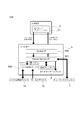
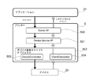
- FIG. 2 is a diagram illustrating a functional configuration of the device control system 100.
- the device control system 100 includes a device XML, which is a command system of XML, which is a markup language, for controlling a device (peripheral device) connected to the printer 5.
- the terminal 3 has an application 31.
- the application 31 is a native application program installed in the terminal 3.
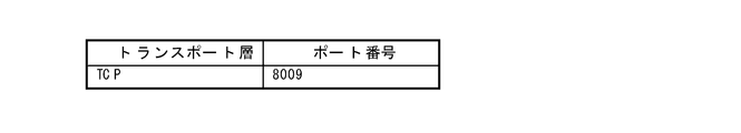
- the device application program interface (API) 33 transmits a request message in XML format to the printer 5 by socket communication (Request).
- a device service interface 501 and a device control script 502 are incorporated in the printer 5.
- the device service interface 501 and the device control script 502 interpret the request message and output the request to the device control script 502.
- the device control script 502 controls the key input device 18 and the serial communication device 19.
- the device control script 502 outputs events of the key input device 18 and the serial communication device 19 and responses of control results to the device service interface 501.
- the key input device 18 includes the keyboard 14 of FIG. 1
- the serial communication device 19 includes the barcode scanner 9 and the cash drawer 13 of FIG.
- the device service interface 501 transmits and receives data to and from the local printer 55.
- the local printer 55 is a printer provided in the printer 5.
- the device service interface 501 transmits and receives data to and from the network printer 7 and the customer display 8.
- the device service interface 501 outputs an XML format response (Response) to the application 31 based on the control results of the network printer 7, the customer display 8 and the local printer 55 and the response of the device control script 502.
- the printer 5 controls the device by the device service interface 501 and the device control script 502.
- the devices controlled in the example of FIG. 2 are the network printer 7, customer display 8, key input device 18, serial communication device 19, and local printer 55.
- the device connected to the printer 5 can be controlled by the terminal 3 using the device XML included in the device control system 100.
- the device XML has the following features. ⁇ There is no need to prepare a separate device (computer, etc.) to control the device. A device that operates with a standard driver provided in the OS of the printer 5 can be used in the device control script 502 without installing the driver. • When a device is accessed, the device is locked exclusively. Even if accessed simultaneously from a plurality of terminals 3, control is not mixed. When the terminal 3 controlling the device releases the device, the released device can be controlled from the other terminal 3.
- the device API 33 has the following features.
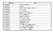
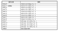
- the command for printing ruled lines can be used when the local printer 55 of the printer 5 or the network printer 7 supports the “ruled line command”. -When the buzzer is connected to the printer 5 or the network printer 7, the buzzer function can be used. -The key code that can be acquired from the keyboard 14 is limited. The key codes that can be acquired from the keyboard 14 are as shown in FIGS. 3A and 3B.
- the printer 5 includes a CPU, a RAM, a flash ROM, an NV (nonvolatile memory), a video controller, an auxiliary storage device (SSD: solidstate drive), an interface, and a local printer (printing unit).
- the printer 5 may include a speaker.
- the local printer is a thermal printer that prints on roll paper of 80 mm width or 58 mm width.
- a POS (point of sales) system can be installed in the printer 5.
- the OS (operating system) of the printer 5 is based on, for example, Windows (registered trademark) and is stored in the auxiliary storage device.
- the printer 5 includes a device control program that is software for the terminal 3 to control a device connected to the printer 5. For this reason, the terminal 3 does not require a driver program.
- the printer 5 includes a local printer included in the printer 5 and a Windows (registered trademark) standard device driver program (APD), a UPOS driver, an OPOS driver, and the like that are software for controlling the device.
- a web application can be installed in the printer 5. Thereby, as shown in FIG. 3, the printer 5 can be used as an application server.
- the web application can use PHP and Perl server-side scripts and SQL Lite database access (server-side scripts).
- FIG. 4 is a diagram illustrating a connection example of devices connected to the printer 5.
- the printer 5 can be connected to the network printer 7, customer display 8, and barcode scanner 9 described above.
- a display 12, a cash drawer 13, and a keyboard 14 can be connected to the printer 5.
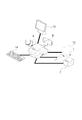
- FIG. 5 is an external perspective view of the printer 5.
- a roll paper cover 51 is provided on the top of the printer 5. The roll paper cover is opened by pressing the cover open button 52, and the roll paper can be taken in and out.
- a discharge port for discharging the roll paper after printing has a manual cutter 53 for manually cutting the roll paper and a cutter cover 54.
- the cutter cover 54 is opened when a paper jam occurs in the local printer of the printer 5 and when the roll paper cover 51 is not opened.
- the printer 5 includes a power switch 56B, a reset button 56A, an LED display unit 57, and a control panel 58.
- the LED display unit 57 includes a disk access LED indicating access to the auxiliary storage device and a status LED.
- the status LED notifies a high temperature warning of the CPU during the operating state of the OS, the standby mode of the OS, the power off state, and the OS startup sequence.
- the control panel 58 includes a power LED, an error LED, a roll paper LED, and a feed button.
- the power LED lights up when power is supplied.
- the error LED is turned off during normal operation, and is turned on when resetting, and when the end of the roll paper is detected and printing is stopped.
- the paper LED is turned off when the remaining amount of roll paper is sufficient, is turned on when the remaining amount is low, and blinks when the self-diagnosis function is executed.
- the feed button is pressed, the roll paper is conveyed line by line or continuously.
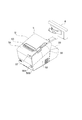
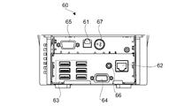
- FIG. 6 is a view showing the connector panel 60.
- the connector panel 60 includes a drawer kick connector 61, an Ethernet connector 62, a USB connector 63, a VGA connector 64, a COM connector 65, a line output 66, and a DC input 67.
- the connector panel 60 corresponds to the connection portion of the present invention.
- the device of the printer 5 includes a local printer 55 provided in the main body of the printer 5. Therefore, the connection unit includes the connector panel 60 and the interface inside the printer 5.
- the cash drawer 13 or an optional buzzer is connected to the drawer kick connector 61.
- the Ethernet connector 62 is connected to the network.
- the USB connector 63 has six USB ports.
- a customer display 8, a barcode scanner 9, a keyboard 14 and other devices are connected to the USB connector 63.
- the display 12 is connected to the VGA connector 64.
- a serial interface of a device that performs serial communication is connected to the COM connector 65.
- the line output 66 is connected to an external speaker.
- FIG. 7 is a diagram illustrating a connection example of the wireless LAN unit 17.
- the wireless LAN unit 17 is inserted into the USB extension cable 15, and the USB extension cable 15 is inserted into the USB connector 63. Thereby, the printer 5 can be connected to the wireless LAN.
- FIG. 8 shows an environment construction workflow.
- the network setting of the printer 5 can be set by any of the following methods. -Configure Windows (registered trademark) network settings on the printer 5. ⁇ Install TMNet WinConfig which is the setting application of the printer 5 and set it in the external device (Windows computer). 2. Connect the device to the printer 5 Connect the device to the printer 5.
- the connectable devices are the customer display 8, the barcode scanner 9, the display 12, the cash drawer 13, the keyboard 14, and the like.
- a device that can be controlled by an OS standard HID driver, a serial communication device that can be operated by an OS standard serial communication driver, and a USB device that can be controlled in the same manner as the serial communication device are included.
- the connector panel 60 of FIG. 6 has only one COM connector 65, a serial-USB conversion cable and a driver program corresponding to serial-USB conversion can connect a plurality of serial communication devices. 3.
- Registration of Device Control Script When a device other than a product supported by the printer 5 is controlled by the printer 5, a device control script prepared by the user is registered. Registration is done from a web browser. 4). Registration of Device A device connected to the printer 5 is registered in the software of the printer 5. Registration is done from a web browser. Procedure 1.
- the web browsers used in ⁇ 5 include a web browser that operates on the terminal 3.
- a method for registering a device control script prepared in advance by the user will be described with reference to FIG.
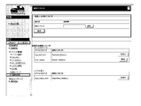
- the registration procedure is as follows. (1) Prepare a customized device control script. (2) Turn on the printer 5. (3) Start a web browser and enter the URL (http: /// IP address of printer 5 / WebConfig /). (4) TMNetWebConfig starts. Click [Web Service Settings]-[Register / Delete] on the screen in FIG. (5) The “control script” screen is displayed. Click [Browse] in [Control script to be registered], and select the device control script to be registered. (6) Click [Register]. Device control scripts are registered and listed in [Registered Control Scripts] at the bottom of the screen.
- TMNetWebConfig is displayed with a web browser to register the device.
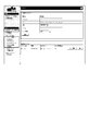
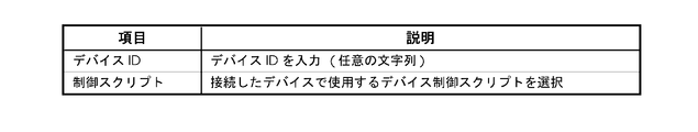
- the registration procedure is as follows. (1) Start a web browser and enter the URL (http: /// IP address of printer 5 / WebConfig /). (2) TMNetWebConfig starts. Click [Web Service Settings]-[Device Registration] on the screen in FIG. 10 according to the type of device to be registered. In FIG. 10, the device is displayed in [Device Registration]. Click the type of device to register.
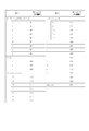
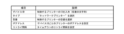
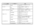
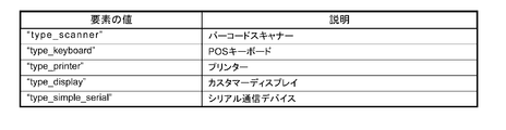
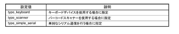
- the device type is selected from five types including a printer, a display, a key input device, a serial communication device, and others. The details of the device type are as shown in FIG.
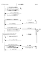
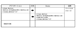
- FIG. 17 The basic programming sequence of Device XML is as shown in FIG. “Applications” in FIG. 17 corresponds to the application 31, “DeviceControl” corresponds to a device control function (device service interface 501), and “Device” indicates a device to be controlled.
- the device returns the execution result.
- the device service interface 501 returns device_data_message or error message.
- the application 31 transmits close_device_nmessage. The connection with the device service interface 501 and the socket I / F communication are disconnected.
- the device service interface 501 transmits a “Cmd ()” command to the device.
- 9 Device closes. 9.1: The device service interface 501 returns a response to the application 31.
- each data item is as shown in FIG. 19A, and the contents of each data are shown in FIG. 19B.
- FIGS. 20A and 20B Examples of communication data between the application 31 and the device service interface 501 are shown in FIGS. 20A and 20B.
- a NULL character is represented by “ ⁇ 0”.
- 20A and 20B show examples of data for establishing a connection, obtaining administrator information, opening a device, controlling a device, and closing a device.
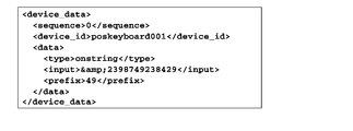
- the arrangement method of ⁇ data> element of ⁇ device_data> message is explained.
- An example of expressing keycodes [49,50,51,52]; is shown in FIG.
- the ePOS-Device XML provides the following: • Message ( Figure 22)
- the message is an XML of a message requested from the application 31 to the printer 5 and a response message from the printer 5 to the application 31.
- -Message data for each device Fig. 23
- XML for storing request and response data for each device to be controlled. This format is a child element of the ⁇ data> element of the ⁇ device_data> message.
- the message data for each device will be described.
- the message data for each device is a child element of the ⁇ data> element of the ⁇ device_data> message, and specifies data for controlling the device.
- the components of message data differ depending on the type of device. Before specifying the data, specify the message data type in the ⁇ type> element, and then specify the child element data.
- ⁇ Type> elements that can be used for each device type are as shown in FIG.
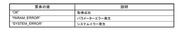
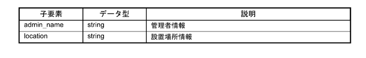
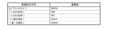
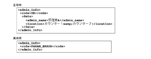
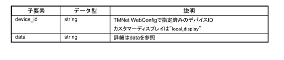
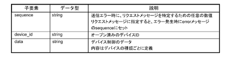
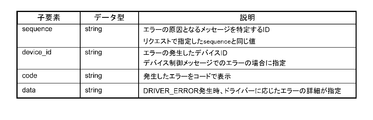
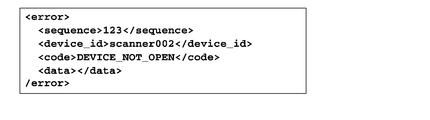
- ⁇ admin_info> The administrator information set in the printer 5 is returned. Information set by TMNet WebConfig. This message is included in [Request]. Request administrator information to the printer 5. [Example] ⁇ admin_info> ⁇ /admin_info> This message is included in [Response]. The administrator information is returned to the application 31. Child elements, data types, and descriptions are shown in FIG. 24A. ⁇ Code The code element is shown in FIG. 24B. ⁇ Data The data element is shown in FIG. 24C. The character string of received data will be described. The character string shown in FIG. 24D is escaped. [Example] FIG. 24E shows an example of a response at normal time and abnormal time.
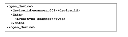
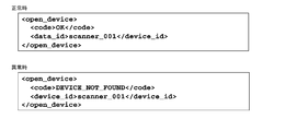
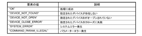
- ⁇ open_device> Enable the device associated with the device ID. The exclusive use right of the specified device is given to the requested application 31. This message is included in [Request]. Specify the device to open. Child elements, data types, and descriptions are shown in FIG. 25A. ⁇ Data The data element is shown in FIG. 25B. [Example] FIG. 25C shows an example of a request. This message is included in [Response]. The device open result is returned to the application 31. Child elements, data types and descriptions are shown in FIG. 25D. ⁇ Code The code element is shown in FIG. 25E. [Example] FIG. 25F shows an example of the response at the normal time and at the abnormal time.
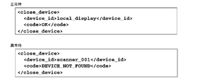
- FIG. 26A shows an example of a request. This message is included in [Response].
- the device closing result is returned to the application 31.
- Child elements, data types and descriptions are shown in FIG. 26C.
- FIG. 26E shows an example of a response at normal time and abnormal time.
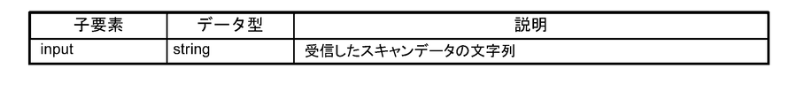
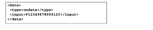
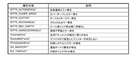
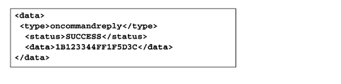
- FIG. 27A shows an example of a request. This message is included in [Response]. Returns data from the device. As a result of device control, events that occurred in the device and input data from the device are included. Child elements, data types and descriptions are shown in FIG. 27C. [Example] FIG. 27D shows an example of a response.
- FIG. 28A shows Child elements, data types, and descriptions.
- FIG. 28B shows an example of a response.
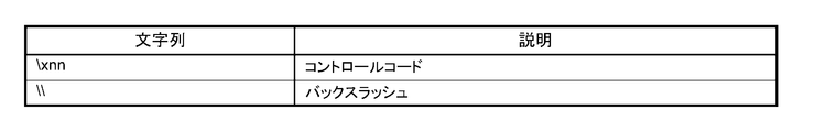
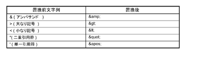
- FIG. 29A The character string of received data will be described.
- the character string in FIG. 29B is escaped.
- FIG. 29C shows an example of a response.
- the printer message data will be described.
- the print data will be described in “Printer control XML” described later.
- ⁇ type> print ⁇ / type> This message is included in [Request].
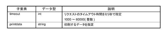
- Child elements, data types, and descriptions are shown in FIG. 30A.
- FIG. 30B shows an example of a request.
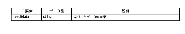
- FIG. 31A shows an example of a response.
- the printer control XML which is an XML document for controlling the printer, will be described.
- the printer message data will be described in “Printer Message Data” described later.
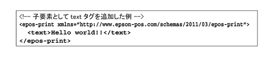
- ⁇ epos-print> This is an XML document transmitted from the application to the printer. Request the printer to execute the specified function.
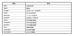
- ⁇ epos-print> has an element. [attribute] ⁇ Xmlns Declare the name of epos-print. [Child Element] Child elements are shown in FIG. 32A. [Example] FIG. 32B shows an example of an XML document.
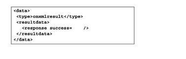
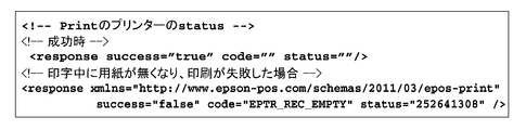
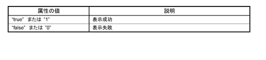
- FIG. 33A An XML document returned from the printer to the application.
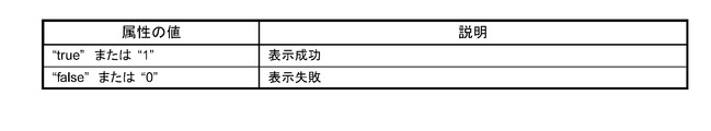
- [attribute] ⁇ Success Get the display result.
- the attribute values are shown in FIG. 33A.
- the attribute values are shown in FIG. 32B.
- the attribute values are shown in FIG. 32C.
- FIG. 33D shows an example of an XML document.
- ⁇ text> Specify the character string to be printed.
- settings for character strings such as character decoration, print position, and line feed amount are also made.
- the character is developed at the current print position with reference to the baseline dot of the character (“Printer specifications” on page 151).
- the horizontal tab, line feed, and the following symbols necessary for printer control are described using the entity reference in FIG. 34A.
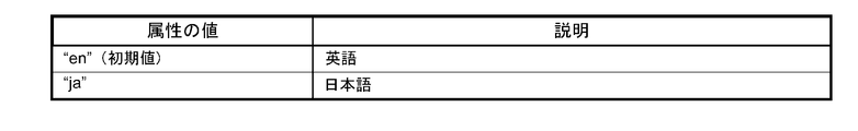
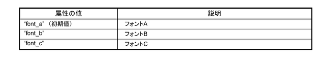
- attribute value ⁇ Lang Specify the target language. The attribute value is shown in FIG. 34B. Character codes that can be printed depend on the specifications of each printer. ⁇ Font Specifies the character font. The attribute value is shown in FIG. 34C.
- FIG. 34M shows an example of setting for printing a character string.
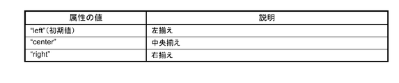
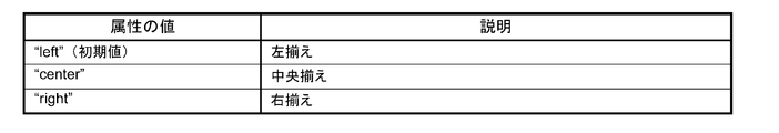
- the “align” attribute is specified in the “line head state”.
- the align attribute set in this element is also applied to the align attribute of the image, logo, barcode, and symbol elements.
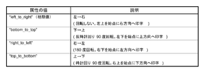
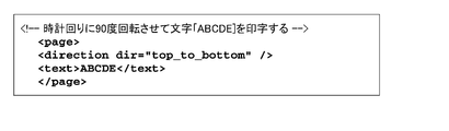
- FIG. 34N shows the rotation specification.
- the rotation specification is invalid.
- the print direction is set from right to left (right_to_left) in direction, and 180 ° rotation printing is performed.
- the rotate attribute set in this element is also applied to the rotate attribute of the barcode and symbol elements.
- Linespc (Initial value: “30”) Specify the paper feed amount per line in dots.
- FIG. 34P shows an example of setting for printing a character string.
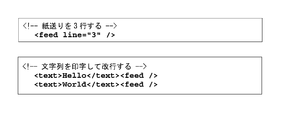
- ⁇ feed> Specify the paper feed amount. Specify the paper feed amount in dots or lines. If no paper feed amount is specified, one line of paper is fed (line feed). Also, set the amount of line breaks per line. [attribute] ⁇ Unit Specify the paper feed amount in dots. ⁇ Line Specify the paper feed amount in lines. ⁇ Linespc (Initial value: “30”) Specify the paper feed amount per line in dots. If the paper feed amount per line is 30 dots, up to 240 lines can be specified. In standard mode and page mode, the line feed amount is kept separately. If the linespc attribute is specified, it affects the linespc attribute of the following ⁇ text> and ⁇ feed>. [Example] FIG. 35 shows an example of an XML document.
- ⁇ image> Specifies raster format bit image data.
- Data type xs: base64Binary The raster format is data obtained by scanning pixels in the horizontal direction with the upper left corner of the image as the origin. The data is 1 bit per pixel in the case of 2 gradations, and 4 bits per pixel in the case of 16 gradations. Also, padding with 0 so that one line of scan data is in bytes.
- the raster image is developed at the current print position based on the lower left dot of the raster image. The print position does not move.
- the print position is set so that the raster image does not protrude from the print area. Because it has an influence on the reading quality of barcodes and 2D codes printed with multi-tone raster images, it prints in 2 gray levels.
- the raster format bit image is created by the ePOS-Print XML generation tool or by the user's application. Consider the following points when creating a user application. -For 2 gradations: Set the image width to a multiple of 8 or set the missing bit to 0. -For 16 gradations: Set the image width to a multiple of 2 or set the missing bits to 0. [attribute] ⁇ Width Specifies the width of the image in dots. ⁇ Height Specifies the height of the image in dots.
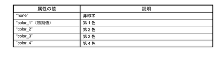
- FIG. 36A Color Specify the text color.
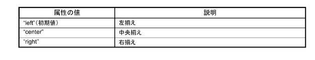
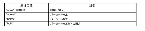
- FIG. 36B Align Specify the print position.
- the attribute values are shown in FIG. 36B.
- the align attribute set in this element is also applied to the align attribute of the text, logo, barcode, and symbol elements.
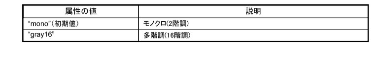
- ⁇ Mode (Optional (optional)) Specify the color mode.
- the attribute values are shown in FIG. 36C. [Example] FIG. 36D shows an example of an XML document.
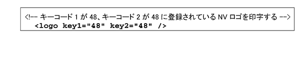
- ⁇ logo> Specify the logo registered in the printer's NV memory. Register the logo in advance on the printer using a model-specific utility or logo registration utility (TMFLogo). In the page mode, the logo is developed at the current print position based on the lower left dot of the logo.
- TMFLogo model-specific utility or logo registration utility
- the logo is developed at the current print position based on the lower left dot of the logo.
- ⁇ Key1 Specify the value of key code 1 set when registering the NV logo.
- ⁇ Key2 Specify the value of key code 2 set when registering the NV logo. Must be specified.
- ⁇ Align Specify the print position.
- the attribute values are shown in FIG. 37A.
- the align attribute set in this element is also applied to the align attribute of the text, image, barcode, and symbol elements.
- FIG. 37B shows an example of an XML document.
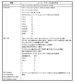
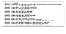
- ⁇ barcode> Specify the barcode data as a character string. If the setting that does not conform to the barcode standard is made, or if the barcode is larger than the print area of the printer, the barcode is not printed. In the page mode, the barcode is developed at the current print position based on the lower left dot (except HRI) of the barcode.
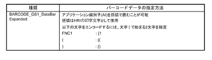
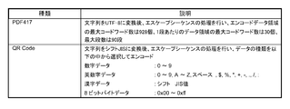
- Barcode type The barcodes shown in FIGS. 38A, 38B, and 38C can be designated. When specifying binary data that cannot be expressed by a character string, it is specified by an escape sequence shown in FIG. 38D.
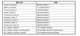
- attribute value ⁇ Type Specify the barcode type. The attribute values are shown in FIG. 38E. ⁇ Hri Specify the location of the HRI.
- the attribute values are shown in FIG. 38F.
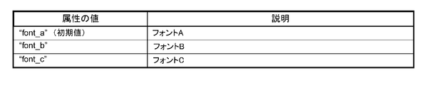
- Font Specify the HRI font.
- the attribute values are shown in FIG. 38G.
- Width (Initial value: “3”) Specifies the module width in dots. Specify an integer value between 2 and 6.
- Height (Initial value: “162”) Specifies the height of the module in dots.
- Align Specify the print position.
- the attribute values are shown in FIG. 38H.
- the align attribute set in this element is also applied to the align attribute of the text, image, logo, and symbol elements.
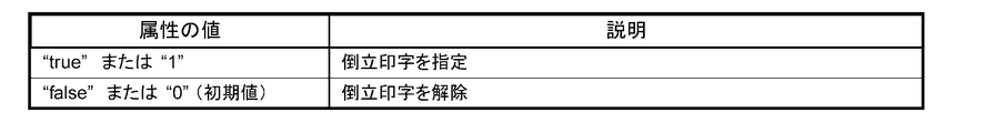
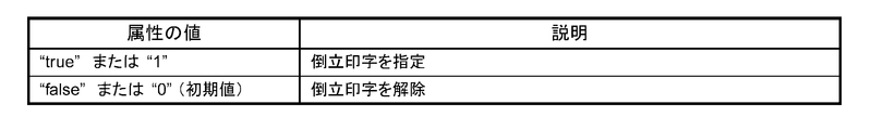
- Rotate Specify inverted printing.
- the attribute values are shown in FIG.
- the rotate attribute set in this element is also applied to the rotate attribute of the text and symbol elements.
- FIG. 38J shows an example of an XML document.
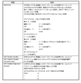
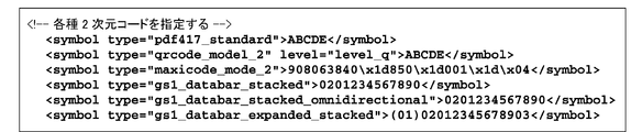
- FIG. 39E ⁇ Level Specify the error correction level.
- the attribute values are shown in FIG. 39E.
- the level is selected according to the type of 2D code. For MaxiCode, 2D GS1DataBar, select default.
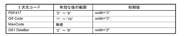
- ⁇ Width Specify the width of one module in dots. Details are shown in FIG. 39F.
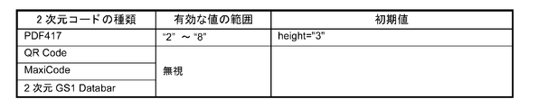
- ⁇ Height Specify the height of one module in dots. Details are shown in FIG. 39G.
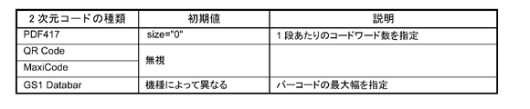
- Size Details are shown in FIG. 39H.
- Align Specify the print position.
- the attribute values are shown in FIG. 39I.
- the align attribute set in this element is also applied to the align attribute of the text, image, logo, and barcode elements.
- ⁇ Rotate Specify inverted printing The attribute values are shown in FIG. 39J.
- the rotate attribute set in this element is also applied to the rotate attribute of the text and barcode elements.
- FIG. 39K shows an example of an XML document.
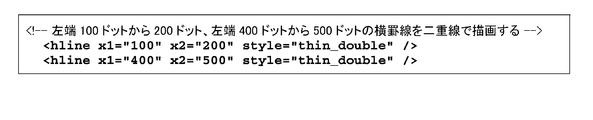
- ⁇ hline> Specify a horizontal ruled line.
- ⁇ X1 Specifies the drawing start position (in dots) of the horizontal ruled line.
- ⁇ X2 Specifies the drawing end position (in dots) of the horizontal ruled line.
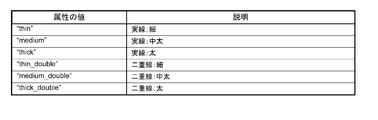
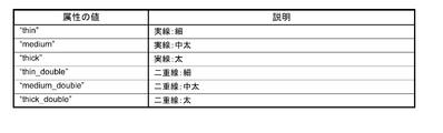
- Style (option) Specifies the type of ruled line.
- the attribute values are shown in FIG. 40A.
- FIG. 40B shows an example of an XML document.
- FIG. 41A shows an example of an XML document.
- FIG. 42A An example of the attribute value is shown in FIG. 42A.
- FIG. 42B shows an example of an XML document.
- FIG. 43A shows an example of an XML document.
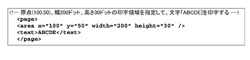
- ⁇ area> Specifies the page mode print area. Set the print area by specifying the origin, width, and height based on the absolute origin. As shown in FIG. 44A, the absolute origin is the upper left dot of the printable area. Specify the print area according to the print contents. When the print data exceeds the print area, the print data is cut off halfway. This element is used in the page element. [attribute] ⁇ X (Initial value: “0”) Specifies the horizontal origin in dots. ⁇ Y (Initial value: “0”) Specify the vertical origin in dots. ⁇ Width (Initial value: Depends on model) Specifies the width of the print area in dots.
- FIG. 44B shows an example of an XML document.
- FIG. 45A shows an example of an XML document.
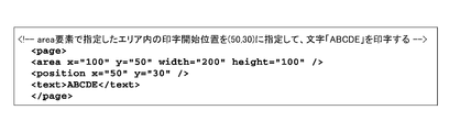
- ⁇ position> Specify the print position in page mode. Specify the print position based on the start point of the print area. The starting point of the print area moves in accordance with the rotation of the print area. This element is used in the page element. [attribute] ⁇ X (Initial value: “0”) Specify the horizontal position in dots. ⁇ Y (Initial value: “21”) Specify the vertical position in dots.
- the print start position (coordinates) is specified according to the print contents. Refer to the following. -When printing a character string Specify the left end of the baseline of the first character. It is an optional feature when printing with the standard size and left justification. When printing a character whose height is twice, specify y to be “42” or more.
- FIG. 46 shows an example of an XML document.
- FIG. 47A ⁇ X1 Specifies the drawing start position (in dots) of the horizontal ruled line.
- ⁇ Y1 Specifies the drawing start position (in dots) of the vertical ruled line.
- ⁇ X2 Specifies the drawing end position (in dots) of the horizontal ruled line.
- ⁇ Y2 Specifies the drawing end position (in dots) of the vertical ruled line.
- ⁇ Style Specifies the type of ruled line.
- the attribute values are shown in FIG. 47A.
- FIG. 47B shows an example of an XML document.
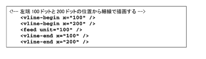
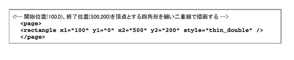
- ⁇ rectangle> Draw a rectangle in page mode. This element is used in the page element. In standard mode, hline element, vline-begin element, and vline-end element are used. [attribute] ⁇ X1 Specifies the drawing start position (in dots) of the horizontal ruled line. ⁇ Y1 Specifies the drawing start position (in dots) of the vertical ruled line. ⁇ X2 Specifies the drawing end position (in dots) of the horizontal ruled line. ⁇ Y2 Specifies the drawing end position (in dots) of the vertical ruled line. ⁇ Style (option) Specifies the type of ruled line. An example of the attribute value is shown in FIG. 48A. [Example] FIG. 48B shows an example of an XML document.
- FIG. 49A An example of the attribute value is shown in FIG. 49A.
- FIG. 49B shows an example of an XML document.
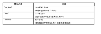
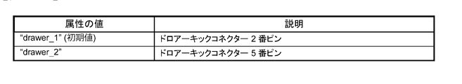
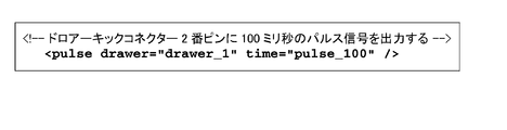
- ⁇ pulse> Specify the signal output for the drawer kick connector. A buzzer can be sounded depending on the model.
- [attribute] ⁇ Drawer (option) Specify the drawer kick connector. The attribute values are shown in FIG. 50A.
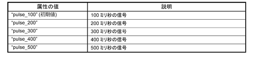
- ⁇ Time (option) Specify the on time of the drawer kick signal.
- the attribute values are shown in FIG. 50B.
- An example of an XML document is shown in the figure.
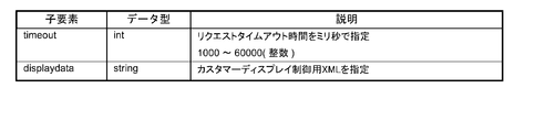
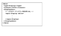
- the customer display message data will be described.
- the display data will be described in “Customer Display Control XML” described later.
- FIG. 52A shows an example of a request.
- FIG. 53A shows an example of a response.
- XML for customer display control which is an XML document for controlling customer display, will be described.
- the message data of the customer display is as described above in the “customer display message data”.
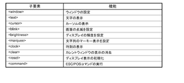
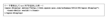
- ⁇ epos-display> An XML document sent from the application to the customer display. Request the customer display to execute the specified function.
- ⁇ epos-display> has child elements necessary for controlling the customer display. [attribute] ⁇ Xmlns Declare the name of epos-display. The child elements are shown in FIG. 54A. [Example] FIG. 54B shows an example of an XML document.
- FIG. 55C shows an example of an XML document.
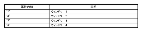
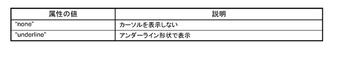
- FIG. 57A ⁇ Destroy Specifies whether to delete the window specified by number.
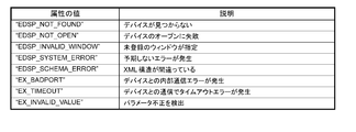
- FIG. 57B The attribute values are shown in FIG. 57B. [Error condition] In the case of an error, the value of FIG. 57C is returned. [Example] FIG. 57D shows an example of an XML document.
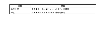
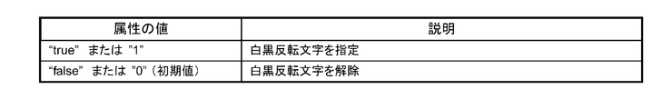
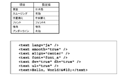
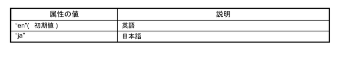
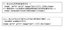
- ⁇ text> Controls the display of character strings. -When attributes x and y are specified, display is performed from the specified cursor position. -If the attributes x and y are not specified, the display starts from the current cursor position. [attribute] ⁇ X Specify the x coordinate (1 to 20) of the text display with an integer value. ⁇ Y Specify the y coordinate (1-2) of the text display as an integer value. ⁇ Reverse Specifies light / dark reversal of display characters. The attribute values are shown in FIG. 58A. ⁇ Lang Specify the language for text display. If omitted, the current setting is maintained. The attribute values are shown in FIG. 58B. [Example] FIG. 58C shows an example of an XML document.
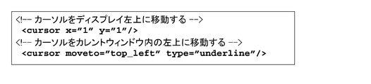
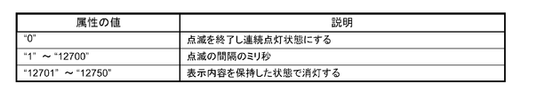
- ⁇ cursor> Control cursor position and display settings. ⁇ Specify the cursor coordinates in the display by specifying x and y. ⁇ Specify the cursor position in the current window by specifying moveto. -If x, y, moveto are specified at the same time, neither is performed. [attribute] ⁇ X Specify an integer value for the x coordinate (1 to 20) of the cursor. ⁇ Y Specifies the y coordinate (1-2) of the cursor as an integer value. ⁇ Moveto Specifies the cursor position in the current window. The attribute values are shown in FIG. 59A. ⁇ Type Specify how to display the cursor. If omitted, the current setting is maintained. The attribute values are shown in FIG. 59B. [Example] FIG. 59C shows an example of an XML document.
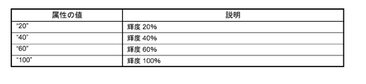
- ⁇ blink> Controls the blinking of the screen. Repeats blinking at the interval specified in interval.
- the actual blinking interval is rounded up by 50ms. For example, when the interval is 1 to 50, 50 ms, and when 51 to 100, 100 ms.
- [attribute] ⁇ Interval Specify the blinking interval as an integer value. The attribute values are shown in FIG. 60A.
- FIG. 60B shows an example of an XML document.
- FIG. 61A shows an example of an XML document.
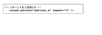
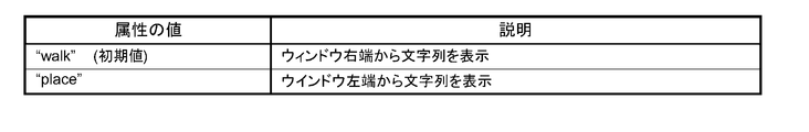
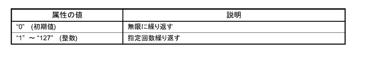
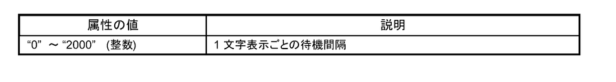
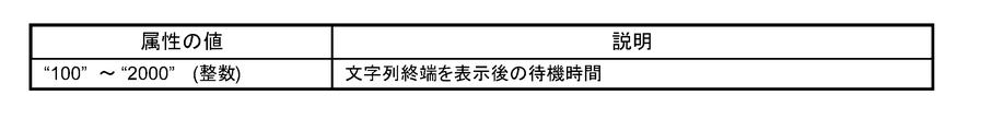
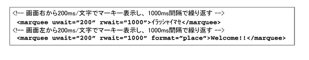
- ⁇ marquee> Controls the marquee display of strings. Displays the specified string one character at a time specified in uwait. After displaying to the end, wait for the time specified by rwait and display again from the beginning.
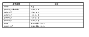
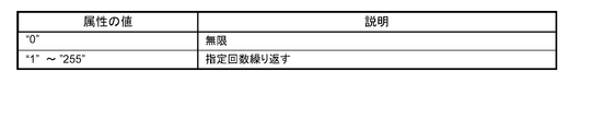
- [attribute] ⁇ Format Specifies the marquee display pattern. The attribute values are shown in FIG. 62A. ⁇ Repeat Specify the number of display repetitions. The attribute values are shown in FIG. 62B. ⁇ Uwait Specifies the waiting interval for displaying one character in milliseconds. The attribute value is shown in FIG. 62C. ⁇ Rwait Specifies the wait interval in milliseconds after displaying the end of the string. The attribute values are shown in FIG. 62D. ⁇ Lang Specify the display language. If omitted, the current setting is maintained. The attribute value is shown in FIG. 62E. [Example] FIG. 62F shows an example of an XML document.
- FIG. 63 shows an example of an XML document.
- FIG. 64 shows an example of an XML document.
- FIG. 65 shows an example of an XML document.
- FIG. 66 shows an example of an XML document.
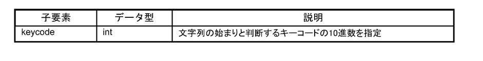
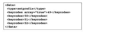
- a key code for determining the start of a character string is designated.
- the key code specified by this message is input, the character string from that point until the Enter key is pressed is notified as an onstring message. For example, it is used when an alternative input of a barcode is performed from a POS keyboard.
- To stop the onstring message send a setprefix message without a keycode.
- a key code for determining the start of a character string for detecting input from the POS keyboard is designated.
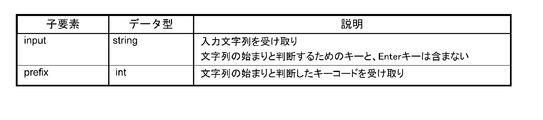
- the child elements are shown in FIG. 68A.
- FIG. 68B shows an example of a request.
- FIG. 70A The message data of the serial device will be described.
- FIG. 70B shows an example of a request.
- FIG. 71A The child elements are shown in FIG. 71A.
- ⁇ Status The attribute values are shown in FIG. 71B.
- FIG. 71C shows an example of a response.
- FIG. 72 is an explanatory diagram regarding the use of a device control script.
- the device control script 502 includes a device connection 503 and a client connection 504.
- the devices of the high-function printer 5 are collectively shown as the device 20.
- the Socket I / F 500 on the printer 5 receives the XML data.
- the Socket I / F 500 passes the received data to the device service interface 501.
- the device service interface 501 generates an object so that a device control script corresponding to the device requested by the open_device message can be used.
- the device 20 can be controlled by the generated object.
- [Device control script object] 73 is passed from the device service interface 501 to the device control script 502.
- the device control script 502 can communicate with the application 31 and the device 20.
- the function using the object of the device control script will be described.
- the following functions can be used using the device control script API.
- An arbitrary event of the device object on the application 31 side can be called.
- -Data can be sent to the device.
- -Data generated from the device can be received.
- the configuration of the device control script will be described.
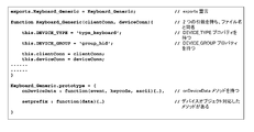
- the device control script has the properties shown in FIGS. Appropriate names are set in the constructor.
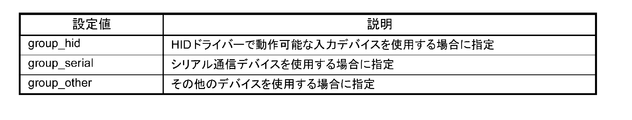
- DEVICE_TYPE property object type: String
- DEVICE_GROUP property object type: String
- a configuration example of the device control script 502 is shown in FIG.
- a list of device control script APIs is shown. The following objects are prepared in the device control script API.
- ClientConnection object A list of APIs is shown in FIG. 77
- DeviceConnection object FIG. 78 shows a list of APIs
- Device control script name object FIG. 79 shows a list of APIs
- the ClientConnection object will be described.
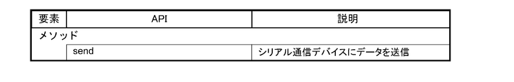
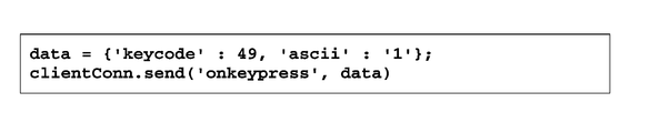
- This object is an object passed to the first parameter of the constructor of the device control script 502. ⁇ Send Send data to the device object running in the browser.
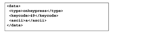
- FIG. In this example, the onkeypress event of the device object is called, and the data parameter of the onkeypress event is used to obtain 49 from data.keycode and '1' from data.ascii.
- the DeviceConnection object will be described. This object is an object passed to the second parameter of the constructor of the device control script 502. ⁇ Send Send data to the serial communication device. [syntax] send (data); [parameter] -Data: Object type: (Buffer) Specify the data to send to the device.
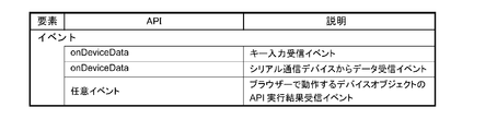
- OnDeviceData event (input device that can be operated by HID driver) This event is an event for receiving data detected from the key input device.
- the event is described in this format.
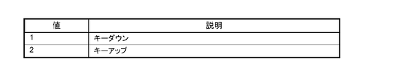
- [parameter] -Event: Object type: (Number) Receives the direction of key operation. A list of values is shown in FIG. -Keycode: Object type: (Number) Receive key code. Examples of key codes are shown in the key code list of FIGS. 3A and 3B.
- -Ascii Object type: (String) Receives the character corresponding to the operated key. If there is no character corresponding to the key code (eg F1 key), it will be undefined.
- -OnDeviceData event (serial communication device) This event is an event for receiving data from the serial communication device.
- events are described in this format. [syntax] onDeviceData (data); [parameter] -Data: Object type: (Buffer) Receives data received from a serial communication device.
- FIG. 83A shows a program environment construction flow.
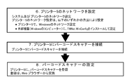
- 1. Set the network of printer 5. Configure network settings for the system and printer 5.
- the network setting of the printer 5 can be set by any of the following methods. -Set the Windows network on the printer 5. -Install and configure TMNet WinConfig on an external device (Windows computer). 2.
- a barcode scanner 9 is connected to the printer 5.
- a barcode scanner 9 is connected to the printer 5.
- Barcode scanner settings. The barcode scanner 9 is registered in the printer 5. Registration is done from a web browser.
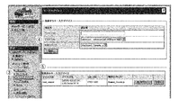
- TMNet WebConfig An example of the TMNet WebConfig screen is shown in FIG. 94A.
- 1. Check whether the barcode scanner 9 is connected to the printer 5, and turn on the printer 5. 2. Start a web browser on the setting computer and enter the URL (http: // IP address of printer 5 / webconfig /). 3. TMNet WebConfig is started. 94A, [Web service setting]-[Device management]-[Key input device] shown in (3) is selected. 4). The “Key input device” screen is displayed. Set the items shown in FIG. 94B in the input field shown in (4) of FIG. 94A and click [Register]. 5. The registered barcode scanner is displayed in [Registered Key Input Device] in (5) of FIG. 94A.
- the device control system 100 connects the terminal 3 that executes the application 31 and the printer 5 including the connector panel 60 to which the device is connected via a network. To do.
- the terminal 3 transmits data described in XML generated by the application 31 to the printer 5.
- the printer 5 receives the XML data transmitted from the terminal 3 via the Socket I / F 500.
- the printer 5 transmits the administrator information held by the printer 5 to the terminal 3 when the terminal 3 requests administrator information with data by the functions of the device service interface 501 and the device control script 502.
- the printer 5 controls the device when the terminal 3 requests control of the device with data. Therefore, the device connected to the printer 5 can be controlled by the terminal 3 connected to the network.
- the terminal 3 is not limited as long as it is a device that can execute an application that generates data described in XML. Since XML is highly versatile, various devices can be used as the terminal 3. In addition, the application of the terminal 3 can be easily developed.
- the printer 5 when the terminal 3 requests administrator information with data including an ⁇ admin_info> message, the printer 5 returns XML data including the administrator name and / or location of the printer 5 to the terminal 3. Further, the printer 5 makes the device controllable when the terminal 3 requests opening of the device with data, and cannot control the controllable device when the terminal 3 requests closing of the device with data. Transition to the state. Further, the data generated by the application 31 includes different message data for each device connected to the printer 5 or message data common to the devices. Further, when controlling the device requested by data, the printer 5 generates a DeviceConnection object that transmits data to the device and a ClientConnection object that transmits data to the terminal 3.
- the present invention is useful for a device control system for controlling a device, and can be applied to device control and a printing apparatus used in a POS system.
- Ethernet connector 63 ... USB connector, 64 ... VGA connector, 65 ... COM connector, 100 ... Device control system, 500 ... Socket I / F, 501 ... Device service interface, 502 ... Device control script, 503 ... Device Connection, 504... Client connection.
Landscapes
- Engineering & Computer Science (AREA)
- Theoretical Computer Science (AREA)
- Physics & Mathematics (AREA)
- General Physics & Mathematics (AREA)
- General Engineering & Computer Science (AREA)
- Human Computer Interaction (AREA)
- Business, Economics & Management (AREA)
- Accounting & Taxation (AREA)
- Computer Networks & Wireless Communication (AREA)
- General Business, Economics & Management (AREA)
- Strategic Management (AREA)
- Finance (AREA)
- Multimedia (AREA)
- Signal Processing (AREA)
- Accessory Devices And Overall Control Thereof (AREA)
- Computer And Data Communications (AREA)
- Information Transfer Between Computers (AREA)
- Facsimiles In General (AREA)
- User Interface Of Digital Computer (AREA)
- Telephonic Communication Services (AREA)
- Selective Calling Equipment (AREA)
Priority Applications (5)
| Application Number | Priority Date | Filing Date | Title |
|---|---|---|---|
| EP13870266.7A EP2800000B1 (en) | 2013-01-02 | 2013-12-26 | Device control system and method for controlling device control system |
| JP2014555400A JP6206417B2 (ja) | 2013-01-02 | 2013-12-26 | プリンター、プリンターの制御方法、及び、デバイス制御システム |
| IN6744DEN2014 IN2014DN06744A (enExample) | 2013-01-02 | 2013-12-26 | |
| CN201380035523.3A CN104412244B (zh) | 2013-01-02 | 2013-12-26 | 设备控制系统以及设备控制系统的控制方法 |
| KR1020157019455A KR101645148B1 (ko) | 2013-01-02 | 2013-12-26 | 디바이스 제어 시스템, 및, 디바이스 제어 시스템의 제어 방법 |
Applications Claiming Priority (2)
| Application Number | Priority Date | Filing Date | Title |
|---|---|---|---|
| US201361748232P | 2013-01-02 | 2013-01-02 | |
| US61/748,232 | 2013-01-02 |
Publications (1)
| Publication Number | Publication Date |
|---|---|
| WO2014106883A1 true WO2014106883A1 (ja) | 2014-07-10 |
Family
ID=51016898
Family Applications (2)
| Application Number | Title | Priority Date | Filing Date |
|---|---|---|---|
| PCT/JP2013/007633 Ceased WO2014106883A1 (ja) | 2013-01-02 | 2013-12-26 | デバイス制御システム、及び、デバイス制御システムの制御方法 |
| PCT/JP2013/007625 Ceased WO2014106882A1 (ja) | 2013-01-02 | 2013-12-26 | デバイス制御システム、印刷装置、及び、デバイス制御システムの制御方法 |
Family Applications After (1)
| Application Number | Title | Priority Date | Filing Date |
|---|---|---|---|
| PCT/JP2013/007625 Ceased WO2014106882A1 (ja) | 2013-01-02 | 2013-12-26 | デバイス制御システム、印刷装置、及び、デバイス制御システムの制御方法 |
Country Status (7)
| Country | Link |
|---|---|
| US (7) | US9280305B2 (enExample) |
| EP (2) | EP2800000B1 (enExample) |
| JP (2) | JP6206417B2 (enExample) |
| KR (3) | KR101652655B1 (enExample) |
| CN (2) | CN104583984B (enExample) |
| IN (2) | IN2014DN06745A (enExample) |
| WO (2) | WO2014106883A1 (enExample) |
Cited By (4)
| Publication number | Priority date | Publication date | Assignee | Title |
|---|---|---|---|---|
| JP2019506652A (ja) * | 2015-11-20 | 2019-03-07 | ヒューレット−パッカード デベロップメント カンパニー エル.ピー.Hewlett‐Packard Development Company, L.P. | Xmlファイルの凝縮 |
| JP2021093068A (ja) * | 2019-12-12 | 2021-06-17 | シチズン時計株式会社 | 機器制御方法、機器制御プログラム、および機器制御装置 |
| US11621838B2 (en) | 2021-03-10 | 2023-04-04 | Seiko Epson Corporation | Information processing device and system |
| US11943327B2 (en) | 2021-03-10 | 2024-03-26 | Seiko Epson Corporation | System, server device, and terminal device |
Families Citing this family (21)
| Publication number | Priority date | Publication date | Assignee | Title |
|---|---|---|---|---|
| KR101579467B1 (ko) * | 2014-02-27 | 2016-01-04 | 엘지전자 주식회사 | 디지털 디바이스 및 그의 서비스 처리 방법 |
| JP5958490B2 (ja) * | 2014-03-31 | 2016-08-02 | コニカミノルタ株式会社 | ウェブシステム、ウェブサーバ、データ配信方法、およびコンピュータプログラム |
| CN109324768B (zh) * | 2014-12-30 | 2021-10-22 | 珠海奔图电子有限公司 | 一种通过移动终端将用户帐号与图像形成设备绑定的方法及系统 |
| US9509942B1 (en) | 2016-02-08 | 2016-11-29 | Picaboo Corporation | Automatic content categorizing system and method |
| CN106970767A (zh) * | 2017-03-03 | 2017-07-21 | 华中科技大学 | 一种实现本地打印机接入云打印平台的方法和系统 |
| US11472579B2 (en) | 2018-12-04 | 2022-10-18 | Gpcp Ip Holdings Llc | Film securing apparatus and method |
| US11752779B2 (en) | 2017-12-12 | 2023-09-12 | Gpcp Ip Holdings Llc | Food service cup dispensers, systems, and methods |
| US20190180392A1 (en) | 2017-12-12 | 2019-06-13 | Gpcp Ip Holdings Llc | Personalized food service material printing systems |
| CN108773205B (zh) * | 2018-06-13 | 2024-04-05 | 马方立 | 智能打印装置及智能打印控制方法 |
| CN108898002B (zh) * | 2018-07-06 | 2021-10-08 | 青岛山景虚拟现实研究院 | 一种可与计算机无线连接的扫描枪装置 |
| JP7320822B2 (ja) * | 2018-08-22 | 2023-08-04 | 株式会社アスタリスク | システム及び周辺装置 |
| JP7135685B2 (ja) * | 2018-09-28 | 2022-09-13 | 株式会社リコー | 電子機器、情報処理システム及び終了操作抑制方法 |
| CN110969032B (zh) * | 2018-09-28 | 2023-09-05 | 捷普电子(广州)有限公司 | 用于扫描物体的扫描设备 |
| US12077337B2 (en) | 2018-12-04 | 2024-09-03 | Yum Connect, LLC | Systems and methods for sealing a container |
| JP7278805B2 (ja) * | 2019-03-04 | 2023-05-22 | キヤノン株式会社 | 情報処理装置、情報処理装置の制御方法及びプログラム |
| WO2020178838A1 (en) | 2019-03-07 | 2020-09-10 | Carbofix In Orthopedics Llc | Devices, assemblies, kits, systems and methods for shaping of elongated elements containing thermoplastic polymers |
| JP2020204950A (ja) * | 2019-06-18 | 2020-12-24 | コニカミノルタ株式会社 | 情報処理システム、情報処理システムの制御方法、装置、及び制御プログラム |
| JP7234849B2 (ja) * | 2019-08-05 | 2023-03-08 | 富士通株式会社 | 情報処理装置、アクセス制御システム及びアクセス制御プログラム |
| RU2758816C1 (ru) * | 2020-06-29 | 2021-11-02 | Георгий Ревазович Хвистани | Система и способ фотофиксации заказов предприятия общественного питания |
| JP2024031249A (ja) * | 2022-08-26 | 2024-03-07 | ブラザー工業株式会社 | 情報処理装置及びデバイス管理方法 |
| JP2024047168A (ja) * | 2022-09-26 | 2024-04-05 | キヤノン株式会社 | 情報処理装置、記録装置、ネットワーク設定方法、およびプログラム |
Citations (3)
| Publication number | Priority date | Publication date | Assignee | Title |
|---|---|---|---|---|
| JP2000500376A (ja) * | 1995-11-20 | 2000-01-18 | クリエーター リミテッド | アイ▲上*▼ドール |
| JP2006135982A (ja) * | 2003-04-24 | 2006-05-25 | Mitsubishi Electric Corp | ネットワーク接続装置、映像情報機器、情報送受信機器、及びネットワーク接続プログラム |
| JP2010134906A (ja) * | 2008-10-20 | 2010-06-17 | Seiko Epson Corp | 情報配信システム、情報配信システムのサービス実現方法およびそのプログラム |
Family Cites Families (40)
| Publication number | Priority date | Publication date | Assignee | Title |
|---|---|---|---|---|
| US5707162A (en) | 1993-11-24 | 1998-01-13 | Seiko Epson Corporation | Modular information processing apparatus |
| JP3399051B2 (ja) | 1993-11-24 | 2003-04-21 | セイコーエプソン株式会社 | Posターミナル及びその印刷装置 |
| US20010021669A1 (en) | 1995-11-20 | 2001-09-13 | Creator Ltd. | I*doll |
| US6368177B1 (en) | 1995-11-20 | 2002-04-09 | Creator, Ltd. | Method for using a toy to conduct sales over a network |
| US6128415A (en) * | 1996-09-06 | 2000-10-03 | Polaroid Corporation | Device profiles for use in a digital image processing system |
| US6519048B1 (en) | 1998-04-28 | 2003-02-11 | Canon Kabushiki Kaisha | Image forming apparatus, image forming method, and storage medium storing computer readable program therein |
| US6289371B1 (en) * | 1998-09-30 | 2001-09-11 | Hewlett-Packard Company | Network scan server support method using a web browser |
| CN1177281C (zh) * | 2000-10-26 | 2004-11-24 | 松下电器产业株式会社 | 印刷图像指定装置及方法 |
| JP2002176675A (ja) * | 2000-12-06 | 2002-06-21 | Seiko Epson Corp | データ伝送システム及びその方法 |
| US20020097417A1 (en) | 2001-01-19 | 2002-07-25 | Chang William Ho | System for universal data output |
| JP3802829B2 (ja) * | 2002-03-14 | 2006-07-26 | 株式会社リコー | 画像情報処理装置、リモート画像情報処理方法およびその方法をコンピュータに実行させるプログラム |
| JP2003288336A (ja) | 2002-03-28 | 2003-10-10 | Brother Ind Ltd | 特定機能代行システム、及び、電子機器、記憶媒体 |
| CN1287334C (zh) | 2002-09-05 | 2006-11-29 | 精工爱普生株式会社 | 打印方法、程序及装置、商品销售数据处理装置、pos系统 |
| JP4341326B2 (ja) | 2002-09-05 | 2009-10-07 | セイコーエプソン株式会社 | 印刷方法、印刷装置、プリンタドライバ、商品販売データ処理装置およびposシステム |
| CN101136836A (zh) * | 2003-04-24 | 2008-03-05 | 三菱电机株式会社 | 影像设备,影像模块单元以及影像设备操作方法 |
| WO2004095293A1 (ja) | 2003-04-24 | 2004-11-04 | Mitsubishi Denki Kabushiki Kaisha | 映像機器、映像モジュールユニット及び映像機器操作方法 |
| KR100538903B1 (ko) | 2003-06-24 | 2005-12-27 | 삼성전자주식회사 | 네트워크 인터페이스 장치 |
| JP2005045437A (ja) * | 2003-07-25 | 2005-02-17 | Fuji Xerox Co Ltd | スキャナシステムおよびその方法 |
| US8937731B2 (en) * | 2003-09-01 | 2015-01-20 | Konica Minolta Business Technologies, Inc. | Image processing apparatus for receiving a request relating to image processing from an external source and executing the received request |
| JP2006344173A (ja) * | 2005-06-10 | 2006-12-21 | Canon Inc | 情報処理装置及びその制御方法 |
| JP4742766B2 (ja) | 2005-09-14 | 2011-08-10 | 富士ゼロックス株式会社 | ネットワークデバイス、デバイスリンクシステムおよびデバイスリンク方法 |
| JP5013742B2 (ja) | 2005-12-15 | 2012-08-29 | 株式会社リコー | 通信装置、情報処理システム、アプリケーション実行方法、アプリケーション実行プログラム及び記録媒体 |
| US20100153225A1 (en) * | 2006-03-26 | 2010-06-17 | Jay Ferro | Printing Dynamic Image Content on Receipts |
| US7658323B2 (en) | 2006-05-24 | 2010-02-09 | Sun Microsystems, Inc. | Point-of-service (POS) and POS application compatability |
| JP2007328558A (ja) | 2006-06-08 | 2007-12-20 | Ricoh Co Ltd | データ処理装置、データ処理システム、データ処理装置の制御方法、データ変換機能付加方法、プログラム及び記録媒体 |
| JP4066383B2 (ja) * | 2006-07-06 | 2008-03-26 | シチズンホールディングス株式会社 | 通信装置および通信制御方法、並びに当該通信装置を備えたプリンタ |
| JP4269182B2 (ja) * | 2006-10-18 | 2009-05-27 | セイコーエプソン株式会社 | 印刷測色制御装置、印刷測色制御方法、印刷測色制御プログラムおよび印刷装置 |
| EP2083404A3 (en) * | 2008-01-24 | 2010-01-06 | Seiko Epson Corporation | Receipt printing processing method, printer and receipt printing processing system |
| JP4473325B2 (ja) * | 2008-05-23 | 2010-06-02 | 富士通株式会社 | 管理装置、ストレージシステム、記憶装置管理方法 |
| JP4777387B2 (ja) * | 2008-06-05 | 2011-09-21 | 株式会社東芝 | スクリプト秘匿実行プログラム及びサーバ装置 |
| JP5272897B2 (ja) * | 2008-07-29 | 2013-08-28 | セイコーエプソン株式会社 | 印刷装置、印刷装置の制御方法及び制御プログラム |
| JP4645723B2 (ja) * | 2008-10-08 | 2011-03-09 | ブラザー工業株式会社 | 通信装置 |
| JP5124779B2 (ja) * | 2008-11-07 | 2013-01-23 | キヤノンイメージングシステムズ株式会社 | デバイス共有システム、デバイス共有クライアント、及びデバイス共有方法 |
| US8643875B2 (en) | 2009-01-09 | 2014-02-04 | Transaction Tree, Inc. | Receipt handling systems, print drivers and methods thereof |
| JP5305999B2 (ja) * | 2009-03-16 | 2013-10-02 | キヤノン株式会社 | 情報処理装置、その制御方法、及びプログラム |
| JP5451355B2 (ja) * | 2009-12-14 | 2014-03-26 | シャープ株式会社 | 情報機器、画像処理装置、情報機器と通信可能な情報処理装置およびそれらを含む情報処理システム |
| US20110194124A1 (en) * | 2010-02-09 | 2011-08-11 | Apple Inc. | Data formats to support driverless printing |
| US20110231272A1 (en) * | 2010-03-16 | 2011-09-22 | App Masters Llc | Retail mobile point-of-sale (POS) software application and retail middleware software application |
| JP5732896B2 (ja) | 2011-02-21 | 2015-06-10 | セイコーエプソン株式会社 | ネットワークシステムおよびネットワークシステムの制御方法 |
| US8700474B2 (en) * | 2012-08-27 | 2014-04-15 | Wal-Mart Stores, Inc. | Deliverying customer specified receipt types at checkout |
-
2013
- 2013-12-24 US US14/140,301 patent/US9280305B2/en active Active
- 2013-12-24 US US14/140,268 patent/US9052853B2/en active Active
- 2013-12-26 JP JP2014555400A patent/JP6206417B2/ja active Active
- 2013-12-26 KR KR1020157019487A patent/KR101652655B1/ko active Active
- 2013-12-26 KR KR1020167022773A patent/KR101736017B1/ko active Active
- 2013-12-26 WO PCT/JP2013/007633 patent/WO2014106883A1/ja not_active Ceased
- 2013-12-26 KR KR1020157019455A patent/KR101645148B1/ko active Active
- 2013-12-26 WO PCT/JP2013/007625 patent/WO2014106882A1/ja not_active Ceased
- 2013-12-26 CN CN201380035049.4A patent/CN104583984B/zh active Active
- 2013-12-26 EP EP13870266.7A patent/EP2800000B1/en active Active
- 2013-12-26 EP EP13870202.2A patent/EP2799999B1/en active Active
- 2013-12-26 IN IN6745DEN2014 patent/IN2014DN06745A/en unknown
- 2013-12-26 IN IN6744DEN2014 patent/IN2014DN06744A/en unknown
- 2013-12-26 JP JP2014555399A patent/JP6277961B2/ja active Active
- 2013-12-26 CN CN201380035523.3A patent/CN104412244B/zh active Active
-
2015
- 2015-05-01 US US14/702,362 patent/US9274730B2/en active Active
- 2015-12-22 US US14/979,291 patent/US10108949B2/en active Active
- 2015-12-30 US US14/984,029 patent/US9495121B2/en active Active
-
2016
- 2016-09-19 US US15/269,172 patent/US10043169B2/en active Active
-
2018
- 2018-06-27 US US16/020,450 patent/US10402809B2/en active Active
Patent Citations (3)
| Publication number | Priority date | Publication date | Assignee | Title |
|---|---|---|---|---|
| JP2000500376A (ja) * | 1995-11-20 | 2000-01-18 | クリエーター リミテッド | アイ▲上*▼ドール |
| JP2006135982A (ja) * | 2003-04-24 | 2006-05-25 | Mitsubishi Electric Corp | ネットワーク接続装置、映像情報機器、情報送受信機器、及びネットワーク接続プログラム |
| JP2010134906A (ja) * | 2008-10-20 | 2010-06-17 | Seiko Epson Corp | 情報配信システム、情報配信システムのサービス実現方法およびそのプログラム |
Cited By (5)
| Publication number | Priority date | Publication date | Assignee | Title |
|---|---|---|---|---|
| JP2019506652A (ja) * | 2015-11-20 | 2019-03-07 | ヒューレット−パッカード デベロップメント カンパニー エル.ピー.Hewlett‐Packard Development Company, L.P. | Xmlファイルの凝縮 |
| US10817473B2 (en) | 2015-11-20 | 2020-10-27 | Hewlett-Packard Development Company, L.P. | XML file condensing |
| JP2021093068A (ja) * | 2019-12-12 | 2021-06-17 | シチズン時計株式会社 | 機器制御方法、機器制御プログラム、および機器制御装置 |
| US11621838B2 (en) | 2021-03-10 | 2023-04-04 | Seiko Epson Corporation | Information processing device and system |
| US11943327B2 (en) | 2021-03-10 | 2024-03-26 | Seiko Epson Corporation | System, server device, and terminal device |
Also Published As
Similar Documents
| Publication | Publication Date | Title |
|---|---|---|
| JP6206417B2 (ja) | プリンター、プリンターの制御方法、及び、デバイス制御システム | |
| KR101600248B1 (ko) | Epos 프린팅 | |
| JP2011135136A (ja) | 画像形成システムおよび画像形成装置 |
Legal Events
| Date | Code | Title | Description |
|---|---|---|---|
| WWE | Wipo information: entry into national phase |
Ref document number: 2013870266 Country of ref document: EP |
|
| 121 | Ep: the epo has been informed by wipo that ep was designated in this application |
Ref document number: 13870266 Country of ref document: EP Kind code of ref document: A1 |
|
| ENP | Entry into the national phase |
Ref document number: 2014555400 Country of ref document: JP Kind code of ref document: A |
|
| NENP | Non-entry into the national phase |
Ref country code: DE |
|
| ENP | Entry into the national phase |
Ref document number: 20157019455 Country of ref document: KR Kind code of ref document: A |