EP2799999B1 - Device control system and method for controlling device control system - Google Patents
Device control system and method for controlling device control system Download PDFInfo
- Publication number
- EP2799999B1 EP2799999B1 EP13870202.2A EP13870202A EP2799999B1 EP 2799999 B1 EP2799999 B1 EP 2799999B1 EP 13870202 A EP13870202 A EP 13870202A EP 2799999 B1 EP2799999 B1 EP 2799999B1
- Authority
- EP
- European Patent Office
- Prior art keywords
- printer
- devices
- request
- device control
- terminal
- Prior art date
- Legal status (The legal status is an assumption and is not a legal conclusion. Google has not performed a legal analysis and makes no representation as to the accuracy of the status listed.)
- Active
Links
- 238000000034 method Methods 0.000 title claims description 233
- 238000013515 script Methods 0.000 claims description 92
- 230000006870 function Effects 0.000 description 68
- 238000004891 communication Methods 0.000 description 39
- 230000004044 response Effects 0.000 description 20
- 238000012360 testing method Methods 0.000 description 5
- 238000012545 processing Methods 0.000 description 4
- 230000004397 blinking Effects 0.000 description 3
- 238000012937 correction Methods 0.000 description 3
- 230000002093 peripheral effect Effects 0.000 description 3
- 238000002360 preparation method Methods 0.000 description 3
- 238000003860 storage Methods 0.000 description 3
- 238000006243 chemical reaction Methods 0.000 description 2
- 238000005520 cutting process Methods 0.000 description 2
- 238000009499 grossing Methods 0.000 description 2
- 238000009434 installation Methods 0.000 description 2
- 239000008186 active pharmaceutical agent Substances 0.000 description 1
- 238000012790 confirmation Methods 0.000 description 1
- 230000001419 dependent effect Effects 0.000 description 1
- 238000002405 diagnostic procedure Methods 0.000 description 1
- 238000003825 pressing Methods 0.000 description 1
- 238000003672 processing method Methods 0.000 description 1
- 239000007787 solid Substances 0.000 description 1
Images


Classifications
-
- G—PHYSICS
- G06—COMPUTING; CALCULATING OR COUNTING
- G06Q—INFORMATION AND COMMUNICATION TECHNOLOGY [ICT] SPECIALLY ADAPTED FOR ADMINISTRATIVE, COMMERCIAL, FINANCIAL, MANAGERIAL OR SUPERVISORY PURPOSES; SYSTEMS OR METHODS SPECIALLY ADAPTED FOR ADMINISTRATIVE, COMMERCIAL, FINANCIAL, MANAGERIAL OR SUPERVISORY PURPOSES, NOT OTHERWISE PROVIDED FOR
- G06Q20/00—Payment architectures, schemes or protocols
- G06Q20/08—Payment architectures
- G06Q20/20—Point-of-sale [POS] network systems
- G06Q20/209—Specified transaction journal output feature, e.g. printed receipt or voice output
-
- G—PHYSICS
- G06—COMPUTING; CALCULATING OR COUNTING
- G06F—ELECTRIC DIGITAL DATA PROCESSING
- G06F3/00—Input arrangements for transferring data to be processed into a form capable of being handled by the computer; Output arrangements for transferring data from processing unit to output unit, e.g. interface arrangements
- G06F3/12—Digital output to print unit, e.g. line printer, chain printer
- G06F3/1201—Dedicated interfaces to print systems
- G06F3/1202—Dedicated interfaces to print systems specifically adapted to achieve a particular effect
- G06F3/1203—Improving or facilitating administration, e.g. print management
- G06F3/1204—Improving or facilitating administration, e.g. print management resulting in reduced user or operator actions, e.g. presetting, automatic actions, using hardware token storing data
-
- G—PHYSICS
- G06—COMPUTING; CALCULATING OR COUNTING
- G06F—ELECTRIC DIGITAL DATA PROCESSING
- G06F3/00—Input arrangements for transferring data to be processed into a form capable of being handled by the computer; Output arrangements for transferring data from processing unit to output unit, e.g. interface arrangements
- G06F3/12—Digital output to print unit, e.g. line printer, chain printer
- G06F3/1201—Dedicated interfaces to print systems
- G06F3/1202—Dedicated interfaces to print systems specifically adapted to achieve a particular effect
- G06F3/1203—Improving or facilitating administration, e.g. print management
- G06F3/1205—Improving or facilitating administration, e.g. print management resulting in increased flexibility in print job configuration, e.g. job settings, print requirements, job tickets
-
- G—PHYSICS
- G06—COMPUTING; CALCULATING OR COUNTING
- G06F—ELECTRIC DIGITAL DATA PROCESSING
- G06F3/00—Input arrangements for transferring data to be processed into a form capable of being handled by the computer; Output arrangements for transferring data from processing unit to output unit, e.g. interface arrangements
- G06F3/12—Digital output to print unit, e.g. line printer, chain printer
- G06F3/1201—Dedicated interfaces to print systems
- G06F3/1202—Dedicated interfaces to print systems specifically adapted to achieve a particular effect
- G06F3/1203—Improving or facilitating administration, e.g. print management
- G06F3/1207—Improving or facilitating administration, e.g. print management resulting in the user being informed about print result after a job submission
-
- G—PHYSICS
- G06—COMPUTING; CALCULATING OR COUNTING
- G06F—ELECTRIC DIGITAL DATA PROCESSING
- G06F3/00—Input arrangements for transferring data to be processed into a form capable of being handled by the computer; Output arrangements for transferring data from processing unit to output unit, e.g. interface arrangements
- G06F3/12—Digital output to print unit, e.g. line printer, chain printer
- G06F3/1201—Dedicated interfaces to print systems
- G06F3/1202—Dedicated interfaces to print systems specifically adapted to achieve a particular effect
- G06F3/1203—Improving or facilitating administration, e.g. print management
- G06F3/1209—Improving or facilitating administration, e.g. print management resulting in adapted or bridged legacy communication protocols, e.g. emulation, protocol extension
-
- G—PHYSICS
- G06—COMPUTING; CALCULATING OR COUNTING
- G06F—ELECTRIC DIGITAL DATA PROCESSING
- G06F3/00—Input arrangements for transferring data to be processed into a form capable of being handled by the computer; Output arrangements for transferring data from processing unit to output unit, e.g. interface arrangements
- G06F3/12—Digital output to print unit, e.g. line printer, chain printer
- G06F3/1201—Dedicated interfaces to print systems
- G06F3/1223—Dedicated interfaces to print systems specifically adapted to use a particular technique
- G06F3/1236—Connection management
-
- G—PHYSICS
- G06—COMPUTING; CALCULATING OR COUNTING
- G06F—ELECTRIC DIGITAL DATA PROCESSING
- G06F3/00—Input arrangements for transferring data to be processed into a form capable of being handled by the computer; Output arrangements for transferring data from processing unit to output unit, e.g. interface arrangements
- G06F3/12—Digital output to print unit, e.g. line printer, chain printer
- G06F3/1201—Dedicated interfaces to print systems
- G06F3/1223—Dedicated interfaces to print systems specifically adapted to use a particular technique
- G06F3/1237—Print job management
- G06F3/1244—Job translation or job parsing, e.g. page banding
- G06F3/1246—Job translation or job parsing, e.g. page banding by handling markup languages, e.g. XSL, XML, HTML
-
- G—PHYSICS
- G06—COMPUTING; CALCULATING OR COUNTING
- G06F—ELECTRIC DIGITAL DATA PROCESSING
- G06F3/00—Input arrangements for transferring data to be processed into a form capable of being handled by the computer; Output arrangements for transferring data from processing unit to output unit, e.g. interface arrangements
- G06F3/12—Digital output to print unit, e.g. line printer, chain printer
- G06F3/1201—Dedicated interfaces to print systems
- G06F3/1223—Dedicated interfaces to print systems specifically adapted to use a particular technique
- G06F3/1237—Print job management
- G06F3/1253—Configuration of print job parameters, e.g. using UI at the client
-
- G—PHYSICS
- G06—COMPUTING; CALCULATING OR COUNTING
- G06F—ELECTRIC DIGITAL DATA PROCESSING
- G06F3/00—Input arrangements for transferring data to be processed into a form capable of being handled by the computer; Output arrangements for transferring data from processing unit to output unit, e.g. interface arrangements
- G06F3/12—Digital output to print unit, e.g. line printer, chain printer
- G06F3/1201—Dedicated interfaces to print systems
- G06F3/1278—Dedicated interfaces to print systems specifically adapted to adopt a particular infrastructure
- G06F3/1279—Controller construction, e.g. aspects of the interface hardware
-
- G—PHYSICS
- G06—COMPUTING; CALCULATING OR COUNTING
- G06F—ELECTRIC DIGITAL DATA PROCESSING
- G06F3/00—Input arrangements for transferring data to be processed into a form capable of being handled by the computer; Output arrangements for transferring data from processing unit to output unit, e.g. interface arrangements
- G06F3/12—Digital output to print unit, e.g. line printer, chain printer
- G06F3/1201—Dedicated interfaces to print systems
- G06F3/1278—Dedicated interfaces to print systems specifically adapted to adopt a particular infrastructure
- G06F3/1284—Local printer device
-
- G—PHYSICS
- G06—COMPUTING; CALCULATING OR COUNTING
- G06F—ELECTRIC DIGITAL DATA PROCESSING
- G06F3/00—Input arrangements for transferring data to be processed into a form capable of being handled by the computer; Output arrangements for transferring data from processing unit to output unit, e.g. interface arrangements
- G06F3/12—Digital output to print unit, e.g. line printer, chain printer
- G06F3/1201—Dedicated interfaces to print systems
- G06F3/1278—Dedicated interfaces to print systems specifically adapted to adopt a particular infrastructure
- G06F3/1285—Remote printer device, e.g. being remote from client or server
- G06F3/1286—Remote printer device, e.g. being remote from client or server via local network
-
- G—PHYSICS
- G06—COMPUTING; CALCULATING OR COUNTING
- G06F—ELECTRIC DIGITAL DATA PROCESSING
- G06F3/00—Input arrangements for transferring data to be processed into a form capable of being handled by the computer; Output arrangements for transferring data from processing unit to output unit, e.g. interface arrangements
- G06F3/12—Digital output to print unit, e.g. line printer, chain printer
- G06F3/1201—Dedicated interfaces to print systems
- G06F3/1278—Dedicated interfaces to print systems specifically adapted to adopt a particular infrastructure
- G06F3/1291—Pool of printer devices: self-managing printing devices in a network, e.g. without a server
-
- G—PHYSICS
- G06—COMPUTING; CALCULATING OR COUNTING
- G06F—ELECTRIC DIGITAL DATA PROCESSING
- G06F3/00—Input arrangements for transferring data to be processed into a form capable of being handled by the computer; Output arrangements for transferring data from processing unit to output unit, e.g. interface arrangements
- G06F3/12—Digital output to print unit, e.g. line printer, chain printer
- G06F3/1201—Dedicated interfaces to print systems
- G06F3/1278—Dedicated interfaces to print systems specifically adapted to adopt a particular infrastructure
- G06F3/1292—Mobile client, e.g. wireless printing
-
- G—PHYSICS
- G06—COMPUTING; CALCULATING OR COUNTING
- G06F—ELECTRIC DIGITAL DATA PROCESSING
- G06F3/00—Input arrangements for transferring data to be processed into a form capable of being handled by the computer; Output arrangements for transferring data from processing unit to output unit, e.g. interface arrangements
- G06F3/12—Digital output to print unit, e.g. line printer, chain printer
- G06F3/1293—Printer information exchange with computer
- G06F3/1294—Status or feedback related to information exchange
-
- G—PHYSICS
- G06—COMPUTING; CALCULATING OR COUNTING
- G06F—ELECTRIC DIGITAL DATA PROCESSING
- G06F3/00—Input arrangements for transferring data to be processed into a form capable of being handled by the computer; Output arrangements for transferring data from processing unit to output unit, e.g. interface arrangements
- G06F3/12—Digital output to print unit, e.g. line printer, chain printer
- G06F3/1297—Printer code translation, conversion, emulation, compression; Configuration of printer parameters
- G06F3/1298—Printer language recognition, e.g. programme control language, page description language
-
- G—PHYSICS
- G06—COMPUTING; CALCULATING OR COUNTING
- G06K—GRAPHICAL DATA READING; PRESENTATION OF DATA; RECORD CARRIERS; HANDLING RECORD CARRIERS
- G06K15/00—Arrangements for producing a permanent visual presentation of the output data, e.g. computer output printers
- G06K15/02—Arrangements for producing a permanent visual presentation of the output data, e.g. computer output printers using printers
-
- G—PHYSICS
- G06—COMPUTING; CALCULATING OR COUNTING
- G06Q—INFORMATION AND COMMUNICATION TECHNOLOGY [ICT] SPECIALLY ADAPTED FOR ADMINISTRATIVE, COMMERCIAL, FINANCIAL, MANAGERIAL OR SUPERVISORY PURPOSES; SYSTEMS OR METHODS SPECIALLY ADAPTED FOR ADMINISTRATIVE, COMMERCIAL, FINANCIAL, MANAGERIAL OR SUPERVISORY PURPOSES, NOT OTHERWISE PROVIDED FOR
- G06Q20/00—Payment architectures, schemes or protocols
- G06Q20/08—Payment architectures
- G06Q20/20—Point-of-sale [POS] network systems
- G06Q20/202—Interconnection or interaction of plural electronic cash registers [ECR] or to host computer, e.g. network details, transfer of information from host to ECR or from ECR to ECR
-
- G—PHYSICS
- G06—COMPUTING; CALCULATING OR COUNTING
- G06Q—INFORMATION AND COMMUNICATION TECHNOLOGY [ICT] SPECIALLY ADAPTED FOR ADMINISTRATIVE, COMMERCIAL, FINANCIAL, MANAGERIAL OR SUPERVISORY PURPOSES; SYSTEMS OR METHODS SPECIALLY ADAPTED FOR ADMINISTRATIVE, COMMERCIAL, FINANCIAL, MANAGERIAL OR SUPERVISORY PURPOSES, NOT OTHERWISE PROVIDED FOR
- G06Q20/00—Payment architectures, schemes or protocols
- G06Q20/08—Payment architectures
- G06Q20/20—Point-of-sale [POS] network systems
- G06Q20/208—Input by product or record sensing, e.g. weighing or scanner processing
-
- G—PHYSICS
- G07—CHECKING-DEVICES
- G07G—REGISTERING THE RECEIPT OF CASH, VALUABLES, OR TOKENS
- G07G1/00—Cash registers
- G07G1/12—Cash registers electronically operated
- G07G1/14—Systems including one or more distant stations co-operating with a central processing unit
-
- H—ELECTRICITY
- H04—ELECTRIC COMMUNICATION TECHNIQUE
- H04N—PICTORIAL COMMUNICATION, e.g. TELEVISION
- H04N1/00—Scanning, transmission or reproduction of documents or the like, e.g. facsimile transmission; Details thereof
- H04N1/00127—Connection or combination of a still picture apparatus with another apparatus, e.g. for storage, processing or transmission of still picture signals or of information associated with a still picture
- H04N1/00326—Connection or combination of a still picture apparatus with another apparatus, e.g. for storage, processing or transmission of still picture signals or of information associated with a still picture with a data reading, recognizing or recording apparatus, e.g. with a bar-code apparatus
- H04N1/00328—Connection or combination of a still picture apparatus with another apparatus, e.g. for storage, processing or transmission of still picture signals or of information associated with a still picture with a data reading, recognizing or recording apparatus, e.g. with a bar-code apparatus with an apparatus processing optically-read information
- H04N1/00334—Connection or combination of a still picture apparatus with another apparatus, e.g. for storage, processing or transmission of still picture signals or of information associated with a still picture with a data reading, recognizing or recording apparatus, e.g. with a bar-code apparatus with an apparatus processing optically-read information with an apparatus processing barcodes or the like
-
- H—ELECTRICITY
- H04—ELECTRIC COMMUNICATION TECHNIQUE
- H04N—PICTORIAL COMMUNICATION, e.g. TELEVISION
- H04N1/00—Scanning, transmission or reproduction of documents or the like, e.g. facsimile transmission; Details thereof
- H04N1/32—Circuits or arrangements for control or supervision between transmitter and receiver or between image input and image output device, e.g. between a still-image camera and its memory or between a still-image camera and a printer device
Definitions
- the present invention relates to a device control system that controls a device, a printer, and a control method of the device control system.
- a device used as a controller for controlling devices is conventionally part of a system that controls devices such as a keyboard and barcode scanner by means of a terminal connected to a network.
- a system having a scanner to which via a network different client computers can be connected.
- On a server which connects the scanner to the network there is stored an application via which respective scanner can be controlled.
- a further system in which a scanner which is connected to a printer having a certain control unit, is controlled via a web application from a web application server is known from EP 2631808 A1 .
- the present invention is directed to the foregoing problem, and an object of the invention is to provide a device control system, and a control method of a device control system that can control devices by a terminal connected to a network.
- FIG. 1 shows the configuration of a device control system 100 including an application server 2 according to a first embodiment applying the invention.
- the device control system 100 includes the application server 2, a terminal 3, and a printer 5 (intelligent printer) .
- the application server 2, terminal 3, and printer 5 are connected over a communication network.
- the device control system 100 has a wireless LAN access point 11, and the application server 2, printer 5, and wireless LAN access point 11 are connected by a wired LAN.
- the wireless LAN access point 11 connects the terminal 3 to the wired LAN.
- the terminal 3 can therefore be used anywhere within communication range of the wireless LAN access point 11.
- a network printer 7, customer display 8, and barcode scanner 9 are connected to the printer 5 as control led devices .
- the network printer 7 is connected to the printer 5 through a network.
- the customer display 8 and barcode scanner 9 are connected through a USB interface described below. These devices are generally called peripheral devices (peripherals), and are referred to below as devices.
- Devices that connect to the printer 5 are not limited to the devices shown in FIG. 1 .
- displays, and key input devices such as keyboards are also included.
- devices that can be controlled by a HID (human interface device) driver standard to the OS are also included.
- serial communication devices that can be operated using a serial communication driver standard to the OS
- USB devices that can be controlled in the same way as serial communication devices.
- the terminal 3 has a network-connectable web browser, and devices connected to the printer 5 can be controlled through this web browser.
- the terminal 3 can be any terminal with a network-connectable web browser, and a tablet computer known from the literature such as shown in FIG. 1 can be used.
- a separate device (such as a computer) used as a controller for controlling the devices does not to be included in the device control system 100.
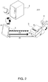
- FIG. 2 shows the configuration of a device control system 200 with an application server 2 according to a second embodiment of the invention.
- This device control system 200 has a terminal 3 and a printer 5.
- the application server 2 is connected to the terminal 3 through a telecommunication network such as the Internet.
- a customer display 8 is connected to the printer 5.
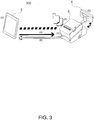
- FIG. 3 shows the configuration of a device control system 300 according to a third embodiment of the invention.
- This example uses the device control system 300 as an application server.
- the terminal 3 is connected to the printer 5.
- a terminal 3 with an installed web browser can thus display a web application and control a device connected to the printer 5.
- the printer 5 has a CPU, RAM, flash ROM, nonvolatile memory, a video controller, an auxiliary storage device (SSD: solid state drive) , interface, and a local printer (print unit) .
- the printer 5 could also have a speaker.
- the local printer is a thermal printer that can print on 80 mm wide or 58 mm wide roll paper.
- the printer 5 can be installed in a POS (point of sale) system.
- the operating system (OS) of the printer 5 is Windows (R) based, for example, and is stored in the auxiliary storage device.
- a device control program which is software for the terminal 3 to control devices connected to the printer 5, is installed to the printer 5. As a result, installing a driver program to the terminal 3 is not necessary.
- the printer 5 also has a Windows (R) standard device driver program (APD), UPOS driver, OPOS driver, or other software for controlling devices and the local printer of the printer 5.
- R Windows
- API standard device driver program
- a web application can be installed to the printer 5. This enables using the printer 5 as an application server as shown in FIG. 3 .
- the web application could, for example, be a PHP and Perl server-side script or SQLite database access script (server-side script).
- FIG. 4 shows an example of device connections to the printer 5.
- the foregoing network printer 7, customer display 8, and barcode scanner 9 can be connected to the printer 5.
- a display 12, cash drawer 13, and keyboard 14 can also be connected to the printer 5.
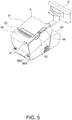
- FIG. 5 shows the external appearance of the printer 5.
- a roll paper cover 51 is disposed to the top of the printer 5.
- the roll paper cover opens when the cover open button 52 is pressed, and roll paper can be loaded.
- a manual cutter 53 for manually cutting the roll paper, and a cutter cover 54, are disposed to the paper exit from which the roll paper is discharged after printing.
- the cutter cover 54 is opened when a paper jam occurs in the local printer of the printer 5, and when the roll paper cover 51 does not open.
- the blade of the manual cutter 53 returns to the home position when the cutter cover 54 opens.
- the printer 5 also has a power switch 56B, reset button 56A, LED display unit 57, and control panel 58.
- the LED display unit 57 includes a disc access LED indicating accessing the auxiliary storage device, and status LEDs. The status LEDs report the operating state of the OS, the standby mode of the OS, that the power is off, the OS start-up sequence, and a high CPU temperature warning.
- the control panel 58 includes a power LED, error LED, roll paper LED, and paper feed button.
- the power LED lights when power is supplied.
- the error LED is off during normal operation, and lights when the printer resets and when the end of the roll paper is detected and printing stops.
- the paper LED is off when sufficient roll paper remains, lights steady when little paper is left, and blinks when the self-diagnostic test is running. Pressing the feed button advances the roll paper one line at a time or continuously.
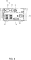
- a connector cover 59 is disposed to the back of the printer 5. Removing the connector cover 59 exposes the connector panel (connection panel) on the back of the printer 5.
- FIG. 6 shows the connection panel 60.
- the connection panel 60 includes a drawer kick-out connector 61, Ethernet connector 62, USB connector 63, VGA connector 64, COM connector 65, line output 66, and DC input connector 67.
- the connection panel 60 is the connection unit of the accompanying claims .
- the local printer 55 incorporated in the printer 5 is also one of the devices connected to the printer 5.
- the connection unit therefore includes the connection panel 60 and an internal interface of the printer 5.
- the cash drawer 13 or an optional buzzer is connected to the drawer kick-out connector 61.
- the Ethernet connector 62 is connected to the network.
- the USB connector 63 has six USB ports.
- the customer display 8, barcode scanner 9, keyboard 14, and other devices are connected to the USB connector 63.
- the display 12 is connected to the VGA connector 64.
- a serial interface for serial communication devices connects to the COM connector 65.
- the line output 66 connects to an external speaker.
- FIG. 7 illustrates connection of a wireless LAN unit 17.
- the wireless LAN unit 17 plugs into a USB extension cable 15, and the USB extension cable 15 plugs into the USB connector 63.
- the printer 5 can thus be connected to a wireless LAN.
- FIG. 8 illustrates the functional configuration of the device control system 100.
- the web browser 31 of the terminal 3 displays a web application 32 provided by the application server 2.
- the web application 32 calls a device application programming interface (API) 33 of the web browser 31.
- the device API 33 is, for example, a Java (R) script, and as described below instantiates an object that controls a device connected to the printer 5.
- the web application 32 calls (APICall) an object of the device API 33.
- the device API 33 sends a request (Request) to the printer 5 by a function of the called object.
- the device service interface 501 of the printer 5 receives the request, and controls a device control script 502.
- the device control script 502 controls a key input device 18 and serial communication device 19.
- the device control script 502 acquires data input by the key input device 18, and outputs data to the device service interface 501.
- the device control script 502 handles data communication with the serial communication device 19, and outputs data received from the serial communication device 19 to the device service interface 501.
- the key input device 18 in this example includes the keyboard 14, and the serial communication devices 19 include the barcode scanner 9 and cash drawer 13.
- the device service interface 501 exchanges data with the local printer 55.
- the local printer 55 is the local print unit of the printer 5.
- the device service interface 501 also exchanges data with the network printer 7 and customer display 8.
- the device service interface 501 outputs device events (Event) and device responses (Response) to the device API 33.
- the device API 33 outputs a response (Callback) to the web application 32.
- a terminal 3 controls a device connected to a printer 5 in the device control system 100 by the operation described above.
- the invention is thus used to control devices (peripherals) connected to a printer 5 in a multi-platform environment.
- devices can be controlled using a personal computer, smartphone, or tablet computer in which a web browser is installed.
- the device API 33 has the following features.
- the device API 33 also has the following features.
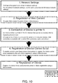
- FIG. 10 shows the flow of work when building an environment.
- the printer 5 can function as a web server to register web content.
- the registered web content can be viewed from the web browser 31 of the terminal 3.
- the registered web content is compressed to a single file in ZIP format containing all content files.
- the name of the ZIP file can be specified as desired.
- the ZIP file name and subfolder names are written using ASCII characters.
- Web content cannot be appended, and all files are registered by overwriting the old files.
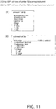
- the URL that is accessed differs according to the folder structure of the ZIP file. Specific examples are shown in FIG. 11 (1) and (2) .
- connectable devices include the customer display 8, barcode scanner 9, display 12, cash drawer 13, and keyboard 14. Also included are devices that can be control ledby a HID driver standard to the OS, serial communication devices that can be operated using a serial communication driver standard to the OS, and USB devices that can be controlled in the same way as serial communication devices.
- the connection panel 60 in FIG. 6 shows only one COM connector 65, but plural serial communication devices can be connected if a serial-USB conversion cable is used and the driver program is compatible with serial-USB conversions.
- a device control script prepared by the user is registered in order for the printer 5 to control devices other than products with which the printer 5 is compatible. Registration is done from the web browser.
- the web browser used for steps 1 to 5 includes the web browser 31.
- step 2 The method of registering web content in step 2 is described in detail.
- the web content registration file is registered by the web browser displaying the TMNetWebConfig utility as shown in FIG. 12 .
- the device control script prepared by the user is registered by the web browser displaying the TMNetWebConfig tool as shown in FIG. 13 .
- This method enables the user to connect a prepared device to the printer 5 and control the device, and enables the user to develop and register a device control script to customize device data processing.
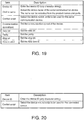
- a device is registered by the web browser displaying the TMNetWebConfig tool as shown in FIG. 14 .
- the device ID of the customer display is a constant, "local-display”. Register the connected customer display 8 by the following steps.
- the device API 33 is embedded as follows.
- the device API 33 is provided to enable using the device control function of this system from a client-side JavaScript.
- the device API 33 is written in JavaScript.
- An example of a filename is device-*. js.
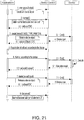
- the programming flow is shown in FIG. 21 .
- FIG. 21 corresponds to a web application 32
- Device Control corresponds to a device control function (device API 33 and device service interface 501)
- Device denotes the controlled device.
- the device API 33 is described in detail next.
- the device API 33 provides the following objects.
- the Device object is described in detail.
- Constructor of a Device object Instantiates and initializes a Device object.
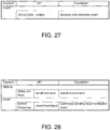
- a string shown in FIG. 28 is returned in the first parameter of the callback.
- the return value is the status of the communication path as shown in FIG. 30 .
- the specified device is exclusively locked, and DEVICE_IN_USE is returned when createDevice is called from another browser. Because the printer is not exclusively locked, a device object can be obtained by createDevice from plural browsers.
- createDevice is executed immediately during a return process after an ondisconnect event, DEVICE_IN_USE is returned. In this event, the createDevice method retries until a value other than DEVICE_IN_USE is obtained.
- the second parameter is a string shown in FIG. 32 .
- the parameter of the callback is a string shown in FIG. 33 .
- the administrator can be set using the TMNetWebConfig utility.
- the location string can be set using the TMNetWebConfig utility.
- Simple JSON data comprising a property name and value set can be declared.
- the Display object is described next.
- Windows are defined to not overlap previously defined windows.
- a window size that fits in the size of the display (20 columns x 20 rows) is specified.
- scrollMode object type: (String)
- the marquee is displayed in the horizontal scroll mode on one line regardless of the scroll mode setting of the display window.
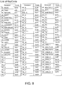
- the key codes are as shown in the key code list in FIG. 9 , for example.
- the Printer object is described next.
- This API setting also applies to barcodes and 2D symbols.
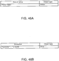
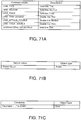
- the return value is shown in FIG. 46A , exceptions in FIG. 46B .
- This API setting also applies to barcodes and 2D symbols.
- characters are printed from the current character position referenced to the baseline dot of the character (see appendix on page 141).
- the printable character codes depend upon the printer specifications.
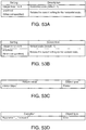
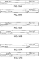
- FIG. 53B Specifies the vertical scaling. Settings are shown in FIG. 53B .
- the return values are shown in FIG. 53C , exceptions in FIG. 53D .
- Inpagemode a raster image is printed at the current print position referenced to the bottom left dot of the raster image .
- the print position does not move.
- HTML5 Canvas images containing images downloaded from a different domain cannot be printed.
- a security error is returned in accordance with JavaScript's same-origin policy.
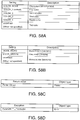
- the logo is previously registered in the printer using a model-specific utility or a logo registration utility (TMFLogo).
- TMFLogo logo registration utility
- a logo is printed from the current printing position referenced to the bottom left dot of the logo.
- Specifies key code 1 of a logo in nonvolatile memory Specify an integer from 0 to 255.
- Specifies key code 2 of a logo in nonvolatile memory Specify an integer from 0 to 255.
- the barcode is printed from the current print position referenced to the bottom left dot (except for HRI) of the barcode.
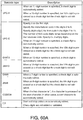
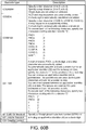
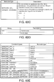
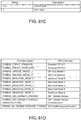
- Barcode data as a string. Barcode types are shown in FIG. 60A , FIG. 60B , and FIG. 60C .
- the barcode is printed from the current printing position referenced to the bottom left dot of the 2D symbol.
- the error correction level is selected according to the type of two-dimensional symbol.
- LEVEL_DEFAULT is selected for MaxiCode and two-dimensional GSlDataBar symbols.
- width Optional parameter, object type: Number
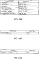
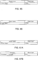
- the return values are shown in FIG. 65 .
- the return values are shown in FIG. 66 .
- the print area is specified according to the content to be printed. If the print data extends beyond the print area, the print data will not be completely printed in the printout.
- This API is used between the above addPageBegin method and the above PageEnd method.
- the width and height of the print area are determined according to the print direction setting.
- the print data may otherwise not be completely printed.
- the print start position (coordinates) is set according to the content to be printed. Refer to the following.
- the buzzer function cannot be used with the drawer.
- This API cannot be used if the printer does not have a buzzer.
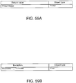
- RGBA full-color HTML5 Canvas image Converts the specified range in a RGBA full-color HTML5 Canvas image to raster image data according to the halftone property and brightness property settings.
- One image pixel equals one printer dot.
- the background color of the image is assumed to be white.
- HTML5 Canvas images containing images downloaded from a different domain cannot be printed.
- a security error is returned in accordance with JavaScript's same-origin policy.
- the Scanner object is described next.
- the specifications of this API can be customized by creating a device control script.
- the received hexadecimal string is separated with ⁇ x.
- the device control script 502 is described next.
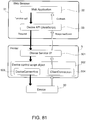
- FIG. 81 describes using a device control script.
- a device control script 502 provided by the device control function of the invention, data processing by a device can be customized and new devices can be used from a web application.
- a device control script 502 has a DeviceConnection object 503 and a ClientConnection object 504.
- devices of the printer 5 are collectively referred to as device 20.
- an object is instantiated so that the device service interface 501 of the printer 5 can use the device control script corresponding to the requested device .
- the device can then be controlled through the instantiated object.
- the obj ects shown in FIG. 82 are then passed to the device control script 502 from the device service interface 501.
- the device control script 502 can communicate with the web application 32 and device 20 as shown in FIG. 81 .
- the DeviceConnection object 503 is an object that sends/receives data with the device 20.
- the ClientConnection object 504 is an object that sends data to a device object on the web browser 31 side, and accesses the device service interface 501.
- a device control script is coded to meet the following conditions .
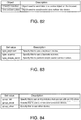
- FIG. 83 A list of settings is shown in FIG. 83 .
- a list of settings is shown in FIG. 84 .
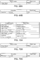
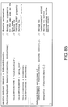
- FIG. 85 The configuration of a sample device control script 502 is shown in FIG. 85 .
- the device control script API is described next.
- the ClientConnection object is described next.
- This object is passed to the first parameter of the constructor of the device control script 502.
- the API "send" command sends data to a device object that runs on a browser.
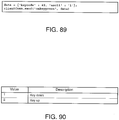
- FIG. 89 An example is shown in FIG. 89 .
- the onkeypress event of the device object is called, and 49 is received from data.keycode and 1 is received from data.ascii using the data parameter of the onkeypress event.
- the DeviceConnection object is described next.
- This object is passed to the second parameter of the constructor of the device control script 502.
- the API "send" command sends data to a serial communication device.
- onDeviceData event input device that can operate with an HID driver
- This event receives data detected from a key input device.
- This event receives data detected from a serial communication device.
- This event is used to receive the results of API execution by a device object that runs on a browser.
- sample program described below enables use as a POS system.
- Sample code for a device API 33 can be created for each device.
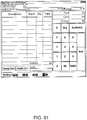
- FIG. 91 shows an example of a POS terminal.
- FIG. 92 shows a sample program for a printer.
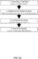
- the work flow for configuring the sample program environment is shown in FIG. 93 .
- FIG. 94 shows a screen for registering the sample program. Register the sample program (device_API_UM_J_Sample.zip) in the printer 5 using the TMNet TMNetWebConfig utility.
- Devices are configured using the TMNet TMNetWebConfig utility in this example.
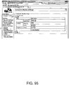
- FIG. 95 shows a customer display configuration screen.
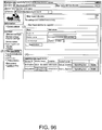
- FIG. 96 shows a POS keyboard/barcode scanner configuration screen. Register the devices using the following procedure.
- the sample program includes the following items. Selecting an item goes to the corresponding screen. Details of each sample are described below.
- This sample program enables operating the customer display and generating sample code for the customer display.
- This sample program enables acquiring input from a POS keyboard.
- the Printer Sample is described in detail next.
- This sample program enables operating the printer and generating sample code for the printer.
- the Printer Sample is used as follows.
- This sample program enables acquiring input from a barcode scanner.
- the Barcode Scanner Sample is used as follows.
- This sample program enables operating like a POS system.
- the POS Terminal Sample is used as follows.
- Preparation is required first. In this preparation, start the sample program and configure each device.
- a device control system 100 has an application server 2 that serves a web application 32; a terminal 3 that is connected to the application server 2 through a network and has a web browser 31 that displays the web application 32; and a printer 5 that has a connection panel 60 to which a device connects, and controls the device connected to the connection panel 60.
- the terminal 3 calls an object that controls a device and is instantiated by the device API 33 to support the device, and sends a request to the printer 5 by the web application 32; and the printer 5 executes a device control script 502 that controls the device, receives requests sent through the device API 33, and controls the device connected to the connection panel 60.
- the invention is not limited to device control system 100, and device control systems 200, 300 can be similarly configured.
- the printer 5 has the functions of the application server 2 ( FIG. 1 ) .
- the device control script 502 has a DeviceConnection object that sends/receives data with a device, and a ClientConnection object that sends data to the device control API.
- the terminal 3 specifies a device connected to the printer 5 and sends a request to start control of the device to the printer 5, and the printer 5 sends a command by the device control script 502 to the device specified by the request and enables controlling the device.
- the first terminal 3 specifies a device connected to the printer 5, sends a request to start control of the device to the printer 5, and the printer 5 enables controlling the device specified in the request, the device is exclusively locked and cannot be controlled by a request sent by the second terminal 3.
- the printer 5 reports to the second terminal 3 that the device is busy when the second terminal 3 calls an object corresponding to the device of the device API 33.
- the device connected to the printer 5 is a local printer or a network printer 7, and when the printer 5 enables control of the device specified by the request, the local printer or the network printer 7 can be controlled by the device control script 502 according to the request sent by the second terminal 3.
- the terminal 3 specifies a device connected to the printer 5 and sends a request instructing ending device control to the printer 5, and the printer 5 sends a command by the device control script 502 to the device specified by the request and terminates the state enabling control of the device.
- the terminal 3 specifies a device connected to the printer 5 and sends a request instructing ending device control to the printer 5; the printer 5 sends a command by the device control script 502 to the device specified by the request and terminates the state enabling control of the device; and the device can be controlled by the printer 5 in response to a request sent by the second terminal 3.
- the terminal 3 detects the connection status of an object instantiated by the device API 33 and the device control script 502 of the printer 5 by means of the device API 33.
- the terminal 3 controls an object of the device API 33 by the web application 32, and calls an event of the device control script 502.
- a customer display is connected to the printer 5 as a device, the terminal 3 sends a request to display on the customer display, and the printer 5 controls displaying on the customer display by the device control script 502 in response to the request.
- a customer display is connected to the printer 5 as a device, the terminal 3 sends a request to display on the customer display, and the printer 5 displays the time on the customer display by the device control script 502 in response to the request, and stops displaying the time when a second request is sent while the time is displayed.
- a printer is connected to printer 5 as a device, the terminal 3 sends a request to register image data in the printer by an object of the device control API, the printer 5 registers the image data in the printer specified by the request, and the printer prints the registered image data.
- color image data rendered by HTML5 Canvas is converted to raster image data and registered in the printer according to a request sent by the terminal 3.
- the terminal 3 specifies a device and sends a request instructing whether or not to encrypt data sent and received between the device and the terminal 3 by an object of the device control API.
- the terminal 3 has an application server 2 that serves a web application 32, and a connection panel 60 to which devices connect, is connected through a network to a printer 5 that controls a device connected to the connection panel 60, has a web browser 31 that displays a web application 32, and through the web application 32 calls an object that controls a device and is instantiated by the device API 33 to support the device, sends a request to the printer 5, and causes the printer 5 to execute a device control script 502 that controls the device.
- the present invention is useful in a device control system that controls a device, and can be applied to controlling devices and printers used in a POS system.
Description
- The present invention relates to a device control system that controls a device, a printer, and a control method of the device control system.
- A device (such as a computer) used as a controller for controlling devices is conventionally part of a system that controls devices such as a keyboard and barcode scanner by means of a terminal connected to a network. From
EP 0 991 227 there is known a system having a scanner to which via a network different client computers can be connected. On a server which connects the scanner to the network, there is stored an application via which respective scanner can be controlled. A further system in which a scanner which is connected to a printer having a certain control unit, is controlled via a web application from a web application server is known fromEP 2631808 A1 . - [PTL 1]
JP-A-2004-152256 - However, there is also a need to use devices such as above by means of a simple configuration.
- The present invention is directed to the foregoing problem, and an object of the invention is to provide a device control system, and a control method of a device control system that can control devices by a terminal connected to a network.
- To achieve the foregoing object, a device control system according to the invention is provided in accordance with
claim 1. In accordance with another aspect of the invention, there is provided a control method in accordance withclaim 11. Preferable features of the invention are defined in the appended dependent claims. -
-
FIG. 1 illustrates a device control system according to a first embodiment of the invention. -
FIG. 2 illustrates a device control system according to a second embodiment of the invention. -
FIG. 3 illustrates a device control system according to a third embodiment of the invention. -
FIG. 4 shows an example of device connections to an intelligent printer. -
FIG. 5 shows an example of a device connection to an intelligent printer. -
FIG. 6 shows a connector panel. -
FIG. 7 illustrates connection of a wireless LAN unit. -
FIG. 8 shows the functional configuration of the device control system. -
FIG. 9 shows examples of key codes that can be acquired from a keyboard. -
FIG. 10 shows the work flow of building a system. -
FIG. 11 shows a method of registering web content. -
FIG. 12 shows a method of registering web content. -
FIG. 13 shows a method of registering a device control script. -
FIG. 14 shows a method of registering a device. -
FIG. 15 shows types of devices selected in device registration. -
FIG. 16 shows input items when registering a network printer. -
FIG. 17 shows input items when registering a customer display. -
FIG. 18 shows input items when registering a key input device. -
FIG. 19 shows input items when registering a serial communication device. -
FIG. 20 shows input items when registering another device. -
FIG. 21 shows the programming flow. -
FIG. 22 shows a device object. -
FIG. 23 shows an object of a Common to Device Object. -
FIG. 24 shows a display object. -
FIG. 25 shows a keyboard object. -
FIG. 26A shows a printer object. -
FIG. 26B shows a printer object. -
FIG. 26C shows a printer object. -
FIG. 27 shows a scanner object. -
FIG. 28 shows a SimpleSerial object. -
FIG. 29 shows a specific example of a connect method. -
FIG. 30 shows an isConnect method. -
FIG. 31 shows a createDevice method. -
FIG. 32 shows a createDevice method. -
FIG. 33 shows a deleteDevice method. -
FIG. 34 shows a createWindow method. -
FIG. 35 shows a moveCursorPosition method. -
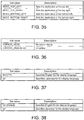
FIG. 36 shows a setCursorType method. -
FIG. 37 shows a addText method. -
FIG. 38 shows a addReverseText method. -
FIG. 39 shows a addMarquee method. -
FIG. 40 shows a addMarquee method. -
FIG. 41 shows a setBrightness method. -
FIG. 42A describes an onreceive event. -
FIG. 42B describes an onreceive event. -
FIG. 42C describes an onreceive event. -
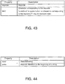
FIG. 43 describes an onkeypress event. -
FIG. 44 describes an onstring event. -
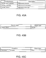
FIG. 45A describes an addTextAlign method. -
FIG. 45B describes an addTextAlign method. -
FIG. 45C describes an addTextAlign method. -
FIG. 46A describes an addTextLineSpace method. -
FIG. 46B describes an addTextLineSpace method. -
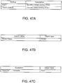
FIG. 47A describes an addTextRotate method. -
FIG. 47B describes an addTextRotate method. -
FIG. 47C describes an addTextRotate method. -
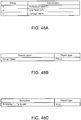
FIG. 48A describes an addText method. -
FIG. 48B describes an addText method. -
FIG. 48C describes an addText method. -
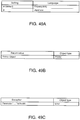
FIG. 49A describes an addTextLang method. -
FIG. 49B describes an addTextLang method. -
FIG. 49C describes an addTextLang method. -
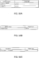
FIG. 50A describes an addTextFont method. -
FIG. 50B describes an addTextFont method. -
FIG. 50C describes an addTextFont method. -
FIG. 51A describes an addTextSmooth method. -
FIG. 51B describes an addTextSmooth method. -
FIG. 51C describes an addTextSmooth method. -
FIG. 52A describes an addTextDouble method. -
FIG. 52B describes an addTextDouble method. -
FIG. 52C describes an addTextDouble method. -
FIG. 52D describes an addTextDouble method. -
FIG. 53A describes an addTextSize method. -
FIG. 53B describes an addTextSize method. -
FIG. 53C describes an addTextSize method. -
FIG. 53D describes an addTextSize method. -
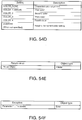
FIG. 54A describes an addTextStyle method. -
FIG. 54B describes an addTextStyle method. -
FIG. 54C describes an addTextStyle method. -
FIG. 54D describes an addTextStyle method. -
FIG. 54E describes an addTextStyle method. -
FIG. 54F describes an addTextStyle method. -
FIG. 55A describes an addTextPosition method. -
FIG. 55B describes an addTextPosition method. -
FIG. 56A describes an addFeedUnit method. -
FIG. 56B describes an addFeedUnit method. -
FIG. 57A describes an addFeedLine method. -
FIG. 57B describes an addFeedLine method. -
FIG. 58A describes an addImage method. -
FIG. 58B describes an addImage method. -
FIG. 58C describes an addImage method. -
FIG. 58D describes an addImage method. -
FIG. 59A describes an addLogo method. -
FIG. 59B describes an addLogo method. -
FIG. 60A describes an addBarcode method. -
FIG. 60B describes an addBarcode method. -
FIG. 60C describes an addBarcode method. -
FIG. 60D describes an addBarcode method. -
FIG. 60E describes an addBarcode method. -
FIG. 60F describes an addBarcode method. -
FIG. 60G describes an addBarcode method. -
FIG. 60H describes an addBarcode method. -
FIG. 60I describes an addBarcode method. -
FIG. 61A describes an addSymbol method. -
FIG. 61B describes an addSymbol method. -
FIG. 61C describes an addSymbol method. -
FIG. 61D describes an addSymbol method. -
FIG. 61E describes an addSymbol method. -
FIG. 61F describes an addSymbol method. -
FIG. 61G describes an addSymbol method. -
FIG. 62A describes an addHLine method. -
FIG. 62B describes an addHLine method. -
FIG. 62C describes an addHLine method. -
FIG. 63A describes an addVLineBegin method. -
FIG. 63B describes an addVLineBegin method. -
FIG. 63C describes an addVLineBegin method. -
FIG. 64A describes an addVLineEnd method. -
FIG. 64B describes an addVLineEnd method. -
FIG. 64C describes an addVLineEnd method. -
FIG. 65 describes an addPageBegin method. -
FIG. 66 describes an addPageEnd method. -
FIG. 67A describes an addPageArea method. -
FIG. 67B describes an addPageArea method. -
FIG. 68A describes an addPageDirection method. -
FIG. 68B describes an addPageDirection method. -
FIG. 68C describes an addPageDirection method. -
FIG. 69A describes an addPagePosition method. -
FIG. 69B describes an addPagePosition method. -
FIG. 70A describes an addPageLine method. -
FIG. 70B describes an addPageLine method. -
FIG. 70C describes an addPageLine method. -
FIG. 71A describes an addPageRectangle method. -
FIG. 71B describes an addPageRectangle method. -
FIG. 71C describes an addPageRectangle method. -
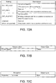
FIG. 72A describes an addCut method. -
FIG. 72B describes an addCut method. -
FIG. 72C describes an addCut method. -
FIG. 73A describes an addPulse method. -
FIG. 73B describes an addPulse method. -
FIG. 73C describes an addPulse method. -
FIG. 73D describes an addPulse method. -
FIG. 74A describes an addSound method. -
FIG. 74B describes an addSound method. -
FIG. 74C describes an addSound method. -
FIG. 74D describes an addSound method. -
FIG. 75A describes an addCommand method. -
FIG. 75B describes an addCommand method. -
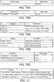
FIG. 76A describes a print method. -
FIG. 76B describes a print method. -
FIG. 76C describes a print method. -
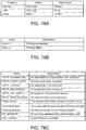
FIG. 77 describes a halftone property. -
FIG. 78A describes an onreceive event. -
FIG. 78B describes an onreceive event. -
FIG. 78C describes an onreceive event. -
FIG. 78D describes an onreceive event. -
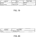
FIG. 79 describes an onerror event. -
FIG. 80 describes an ondata event. -
FIG. 81 describes using a device control script. -
FIG. 82 describes an object of a device control script. -
FIG. 83 shows a list of device control script properties. -
FIG. 84 shows a list of device control script properties. -
FIG. 85 shows a specific example ofdevice control script 502. -
FIG. 86 shows an API list of the ClientConnection. -
FIG. 87 shows an API list of the DeviceConnection object. -
FIG. 88 shows an API list of the device control script name object. -
FIG. 89 describes an API of the ClientConnection object. -
FIG. 90 describes an onDeviceData event. -
FIG. 91 shows an example of a POS terminal. -
FIG. 92 shows a sample program for a printer. -
FIG. 93 shows the flow of setting the sample program environment. -
FIG. 94 shows an example of a screen for registering the sample program. -
FIG. 95 shows a window for setting the customer display. -
FIG. 96 shows a window for setting the POS keyboard/barcode scanner. -
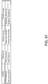
FIG. 97 shows an example of device settings. -
FIG. 98 shows a display sample of the sample program. -
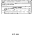
FIG. 99A shows a example of a Customer Display Sample screen. -
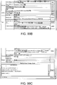
FIG. 99B shows a example of a Customer Display Sample screen. -
FIG. 99C shows a example of a Customer Display Sample screen. -
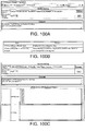
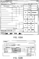
FIG. 100A shows an example of Keyboard Sample screen. -
FIG. 100B shows an example of input and the result to the Keyboard Sample screen. -
FIG. 100C shows an example of a Keyboard Sample screen. -
FIG. 101A shows an example of a Printer Sample screen. -
FIG. 101B shows an example of a Printer Sample screen. -
FIG. 101C shows an example of a Printer Sample screen. -
FIG. 102A shows an example of a Barcode Scanner Sample screen. -
FIG. 102B shows an example of a Barcode Scanner Sample screen. -
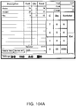
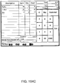
FIG. 103A shows an example of a POS Terminal Sample screen. -
FIG. 103B shows an example of a Settings screen. -
FIG. 104A shows an example of a POS Terminal Sample screen. -
FIG. 104B shows an example of a POS Terminal Sample screen. -
FIG. 104C shows an example of a POS Terminal Sample screen. - A preferred embodiment of the invention is described below with reference to the accompanying figures.
-
FIG. 1 shows the configuration of adevice control system 100 including anapplication server 2 according to a first embodiment applying the invention. - The
device control system 100 includes theapplication server 2, aterminal 3, and a printer 5 (intelligent printer) . In thisdevice control system 100, theapplication server 2,terminal 3, andprinter 5 are connected over a communication network. In the example shown inFIG. 1 , thedevice control system 100 has a wirelessLAN access point 11, and theapplication server 2,printer 5, and wirelessLAN access point 11 are connected by a wired LAN. The wirelessLAN access point 11 connects theterminal 3 to the wired LAN. Theterminal 3 can therefore be used anywhere within communication range of the wirelessLAN access point 11. - A
network printer 7,customer display 8, andbarcode scanner 9 are connected to theprinter 5 as control led devices . Thenetwork printer 7 is connected to theprinter 5 through a network. Thecustomer display 8 andbarcode scanner 9 are connected through a USB interface described below. These devices are generally called peripheral devices (peripherals), and are referred to below as devices. - Devices that connect to the
printer 5 are not limited to the devices shown inFIG. 1 . For example, displays, and key input devices such as keyboards are also included. Also included are devices that can be controlled by a HID (human interface device) driver standard to the OS, serial communication devices that can be operated using a serial communication driver standard to the OS, and USB devices that can be controlled in the same way as serial communication devices. - The
terminal 3 has a network-connectable web browser, and devices connected to theprinter 5 can be controlled through this web browser. - The
terminal 3 can be any terminal with a network-connectable web browser, and a tablet computer known from the literature such as shown inFIG. 1 can be used. A separate device (such as a computer) used as a controller for controlling the devices does not to be included in thedevice control system 100. - Operation of the
device control system 100 is described next. - (1) Place a web application on the
application server 2. - (2) Display the web application with the web browser of the
terminal 3. - (3) The web browser of the
terminal 3 sends a request message to theprinter 5. - (4) The
printer 5 receives the request message. Based on the received request message, theprinter 5 sends data to a device that can be controlled by theprinter 5. - (5) The
network printer 7,customer display 8, andbarcode scanner 9 connected to theprinter 5 are controlled. - (6) The
printer 5 returns a response to the web application. -
FIG. 2 shows the configuration of adevice control system 200 with anapplication server 2 according to a second embodiment of the invention. Thisdevice control system 200 has aterminal 3 and aprinter 5. In thisdevice control system 200, theapplication server 2 is connected to theterminal 3 through a telecommunication network such as the Internet. In the example inFIG. 2 , acustomer display 8 is connected to theprinter 5. - Operation of this
device control system 200 is described next. - (1) Place a web application on the
application server 2. - (2) Display the web application with the web browser of the
terminal 3. - (3) The web browser of the
terminal 3 sends a request message to theprinter 5. - (4) The
printer 5 receives the request message. Based on the received request message, theprinter 5 sends data to a device that can be controlled by theprinter 5. - (5) The
network printer 7,customer display 8, andbarcode scanner 9 connected to theprinter 5 are controlled. - (6) The
printer 5 returns a response to the web application. -
FIG. 3 shows the configuration of adevice control system 300 according to a third embodiment of the invention. This example uses thedevice control system 300 as an application server. In thisdevice control system 300, theterminal 3 is connected to theprinter 5. - Operation of the
device control system 300 is described next. - (1) Place a web application on the
printer 5. - (2) Display the web application with the web browser of the
terminal 3. - (3) The web browser of the
terminal 3 sends a request message to theprinter 5. - (4) The
printer 5 receives the request message. Based on the received request message, theprinter 5 sends data to a device that can be controlled by theprinter 5. - (5) The
network printer 7,customer display 8, andbarcode scanner 9 connected to theprinter 5 are controlled. - (6) The
printer 5 returns a response to the web application. - In a system applying the invention, a
terminal 3 with an installed web browser can thus display a web application and control a device connected to theprinter 5. - The configuration of the
printer 5 is described next. - The
printer 5 has a CPU, RAM, flash ROM, nonvolatile memory, a video controller, an auxiliary storage device (SSD: solid state drive) , interface, and a local printer (print unit) . Theprinter 5 could also have a speaker. The local printer is a thermal printer that can print on 80 mm wide or 58 mm wide roll paper. - The
printer 5 can be installed in a POS (point of sale) system. The operating system (OS) of theprinter 5 is Windows (R) based, for example, and is stored in the auxiliary storage device. - A device control program, which is software for the
terminal 3 to control devices connected to theprinter 5, is installed to theprinter 5. As a result, installing a driver program to theterminal 3 is not necessary. - The
printer 5 also has a Windows (R) standard device driver program (APD), UPOS driver, OPOS driver, or other software for controlling devices and the local printer of theprinter 5. - A web application can be installed to the
printer 5. This enables using theprinter 5 as an application server as shown inFIG. 3 . The web application could, for example, be a PHP and Perl server-side script or SQLite database access script (server-side script). -
FIG. 4 shows an example of device connections to theprinter 5. - The foregoing
network printer 7,customer display 8, andbarcode scanner 9 can be connected to theprinter 5. Adisplay 12,cash drawer 13, andkeyboard 14 can also be connected to theprinter 5.FIG. 5 shows the external appearance of theprinter 5. - A
roll paper cover 51 is disposed to the top of theprinter 5. The roll paper cover opens when the coveropen button 52 is pressed, and roll paper can be loaded. Amanual cutter 53 for manually cutting the roll paper, and acutter cover 54, are disposed to the paper exit from which the roll paper is discharged after printing. Thecutter cover 54 is opened when a paper jam occurs in the local printer of theprinter 5, and when theroll paper cover 51 does not open. The blade of themanual cutter 53 returns to the home position when thecutter cover 54 opens. Theprinter 5 also has apower switch 56B, resetbutton 56A,LED display unit 57, andcontrol panel 58. TheLED display unit 57 includes a disc access LED indicating accessing the auxiliary storage device, and status LEDs. The status LEDs report the operating state of the OS, the standby mode of the OS, that the power is off, the OS start-up sequence, and a high CPU temperature warning. - The
control panel 58 includes a power LED, error LED, roll paper LED, and paper feed button. The power LED lights when power is supplied. The error LED is off during normal operation, and lights when the printer resets and when the end of the roll paper is detected and printing stops. The paper LED is off when sufficient roll paper remains, lights steady when little paper is left, and blinks when the self-diagnostic test is running. Pressing the feed button advances the roll paper one line at a time or continuously. - A
connector cover 59 is disposed to the back of theprinter 5. Removing theconnector cover 59 exposes the connector panel (connection panel) on the back of theprinter 5. -
FIG. 6 shows theconnection panel 60. Theconnection panel 60 includes a drawer kick-out connector 61,Ethernet connector 62,USB connector 63,VGA connector 64,COM connector 65,line output 66, andDC input connector 67. Theconnection panel 60 is the connection unit of the accompanying claims . However, thelocal printer 55 incorporated in theprinter 5 is also one of the devices connected to theprinter 5. The connection unit therefore includes theconnection panel 60 and an internal interface of theprinter 5. - The
cash drawer 13 or an optional buzzer is connected to the drawer kick-out connector 61. TheEthernet connector 62 is connected to the network. TheUSB connector 63 has six USB ports. Thecustomer display 8,barcode scanner 9,keyboard 14, and other devices are connected to theUSB connector 63. Thedisplay 12 is connected to theVGA connector 64. A serial interface for serial communication devices connects to theCOM connector 65. Theline output 66 connects to an external speaker. -
FIG. 7 illustrates connection of awireless LAN unit 17. Thewireless LAN unit 17 plugs into aUSB extension cable 15, and theUSB extension cable 15 plugs into theUSB connector 63. Theprinter 5 can thus be connected to a wireless LAN. - An embodiment of the invention is described in detail below using the
device control system 100 as an example. -
FIG. 8 illustrates the functional configuration of thedevice control system 100. - The
web browser 31 of theterminal 3 displays aweb application 32 provided by theapplication server 2. Theweb application 32 calls a device application programming interface (API) 33 of theweb browser 31. Thedevice API 33 is, for example, a Java (R) script, and as described below instantiates an object that controls a device connected to theprinter 5. Theweb application 32 calls (APICall) an object of thedevice API 33. Thedevice API 33 sends a request (Request) to theprinter 5 by a function of the called object. - The
device service interface 501 of theprinter 5 receives the request, and controls adevice control script 502. Thedevice control script 502 controls akey input device 18 andserial communication device 19. Thedevice control script 502 acquires data input by thekey input device 18, and outputs data to thedevice service interface 501. Thedevice control script 502 handles data communication with theserial communication device 19, and outputs data received from theserial communication device 19 to thedevice service interface 501. Thekey input device 18 in this example includes thekeyboard 14, and theserial communication devices 19 include thebarcode scanner 9 andcash drawer 13. - The
device service interface 501 exchanges data with thelocal printer 55. Thelocal printer 55 is the local print unit of theprinter 5. Thedevice service interface 501 also exchanges data with thenetwork printer 7 andcustomer display 8. Thedevice service interface 501 outputs device events (Event) and device responses (Response) to thedevice API 33. Thedevice API 33 outputs a response (Callback) to theweb application 32. - A
terminal 3 controls a device connected to aprinter 5 in thedevice control system 100 by the operation described above. - The invention is thus used to control devices (peripherals) connected to a
printer 5 in a multi-platform environment. By using this system, devices can be controlled using a personal computer, smartphone, or tablet computer in which a web browser is installed. - The
device API 33 has the following features. - * Can encrypt the content of device communications.
- * Devices that operate according to a driver standard to the OS of the
printer 5 can be used through thedevice control script 502 without installing a specific driver on theprinter 5. Because thedevice control script 502 is written in JavaScript (R), thedevice control script 502 can be developed in the same language as theweb application 32. - * When a device is accessed using the
device API 33, the device is automatically exclusively locked. Multiple terminals therefore cannot access and control a device at the same time. When theterminal 3 controlling a device releases the device, the device can then be controlled from anotherterminal 3. - The
device API 33 also has the following features. - * Commands that print lines can be used when the
network printer 7 or thelocal printer 55 of theprinter 5 supports a line command. - * Buzzer functions can be used when the
printer 5 ornetwork printer 7 is connected to a buzzer. - * Key codes that can be acquired from the
keyboard 14 are limited. Key codes that can be acquired from thekeyboard 14 are shown inFIG. 9 . - Building a
device service interface 501 environment is described next. -
FIG. 10 shows the flow of work when building an environment. - Configure the system and
printer 5 network. These settings can be made using the same procedure used for configuring a windows (R) network. - Register the web content in the
printer 5 from the web browser. - The
printer 5 can function as a web server to register web content. The registered web content can be viewed from theweb browser 31 of theterminal 3. - The registered web content is compressed to a single file in ZIP format containing all content files. The name of the ZIP file can be specified as desired. The ZIP file name and subfolder names are written using ASCII characters.
- Web content cannot be appended, and all files are registered by overwriting the old files. When accessing web content registered in the
printer 5 from theterminal 3, for example, the URL that is accessed differs according to the folder structure of the ZIP file. Specific examples are shown inFIG. 11 (1) and (2) . - Connect a device to the
printer 5. As described above, connectable devices include thecustomer display 8,barcode scanner 9,display 12,cash drawer 13, andkeyboard 14. Also included are devices that can be control ledby a HID driver standard to the OS, serial communication devices that can be operated using a serial communication driver standard to the OS, and USB devices that can be controlled in the same way as serial communication devices. Theconnection panel 60 inFIG. 6 shows only oneCOM connector 65, but plural serial communication devices can be connected if a serial-USB conversion cable is used and the driver program is compatible with serial-USB conversions. - A device control script prepared by the user is registered in order for the
printer 5 to control devices other than products with which theprinter 5 is compatible. Registration is done from the web browser. - Register the device connected to the
printer 5 in theprinter 5 software. Registration is done from the web browser. - The web browser used for
steps 1 to 5 includes theweb browser 31. - The method of registering web content in
step 2 is described in detail. - The web content registration file is registered by the web browser displaying the TMNetWebConfig utility as shown in
FIG. 12 . - The registration steps are as follow.
- (1) Combine the web content to register in a single ZIP file.
- (2) Turn the
printer 5 power on. - (3) Start the web browser, and input the URL (http://IP address of
printer 5/TMNetWebConfig/). - (4) The TMNetWebConfig utility starts. Click on [Web service settings] - [Update settings] in the window shown in
FIG. 11 . - (5) The Web Content Update Settings screen is displayed. Click on [Browse] in the web content file field, and select the ZIP file containing the web content that was prepared in step (1).
- (6) Click [Upload].
- Registering a device control script in
step 4 is described in detail. - The device control script prepared by the user is registered by the web browser displaying the TMNetWebConfig tool as shown in
FIG. 13 . This method enables the user to connect a prepared device to theprinter 5 and control the device, and enables the user to develop and register a device control script to customize device data processing. - The registration steps are as follow.
- (1) Prepare a customized device control script.
- (2) Turn the
printer 5 power on. - (3) Start the web browser, and input the URL (http://IP address of
printer 5/TMNetWebConfig/). - (4) Start the TMNetWebConfig utility. Click on [Web service settings] -[Register/delete] in the window shown in
FIG. 12 . - (5) The Control Script screen is displayed. Click on [Browse] in the Control script to be registered field, and select the device control script to register.
- (6) Click [Register]. The device control script is registered and listed in the Registered control scripts field in the bottom of the window.
- Registering a device in
step 5 is described in detail. - A device is registered by the web browser displaying the TMNetWebConfig tool as shown in
FIG. 14 . - The registration steps are as follow.
- (1) Start the web browser, and input the URL (http://IP address of
printer 5/TMNetWebConfig/). - (2) Start the TMNetWebConfig utility. From [Web service settings] - [Device registration] in the window shown in
FIG. 14 , click on the type of device to register. Adevice list 301 is displayed under Device registration in the screen shown inFIG. 14 . Click on the type of device to register from thedevice list 301. The type of device in this embodiment can be selected from five types, printer, display, key input device, serial communication device, and other as shown inFIG. 15 . Details about the types of devices are as shown inFIG. 15 . - (3) A configuration screen is displayed for each device. The connected device is registered in the
printer 5. - Registration of the local printer incorporated in the
printer 5 can be confirmed as follows. - (3-1-1) Check that "
printer 5" is registered for the device ID "local_printer" in the Registered Printer field in the screen shown inFIG. 14 . - (3-1-2) Click on [Test printing] . Check that TEST_PRINT is printed by the local printer.
- (3-1-3) Register the connected
network printer 7. - Register the
network printer 7 by the following steps. - (3-1-3-1) Set the items shown in
FIG. 16 (device ID, type, model number, IP address, retry interval), and click [Register]. - (3-1-3-2) After confirming the printer is added to the Registered Printer list, click [Test printing] . Confirm that TEST_PRINT is printed by the registered
network printer 7. - The device ID of the customer display is a constant, "local-display". Register the connected
customer display 8 by the following steps. - (3-2-1) Select Use in the screen shown in
FIG. 14 . - (3-2-2) Set the items (communication settings, brightness settings) in
FIG. 17 , and click [Register]. - (3-2-3) Click [Test display] . Confirm that text is displayed on the
customer display 8. - Register the connected
key input device 18 by the following steps . - (3-3-1) Set the items (device ID, device name, control script) in
FIG. 18 , and click [Register]. - (3-3-2) After confirming the registered device was added to the Registered Key Input Device field, click [Operating test].
- (3-3-3) A screen will be displayed by the web browser. Operate the
key input device 18, and confirm that the result is displayed as operated. - Register the connected
serial communication device 19 by the following steps. - (3-4-1) Set the items (device ID, device name, control script, communication speed, data bit, parity, stop bit, flow control) shown in
FIG. 19 for the connectedserial communication device 19, and click [Register] . - (3-4-2) Confirm that the device is added to the Registered Serial Communication Device field.
- Register another connected device by the following steps.
- (3-5-1) Set the items (device ID, control script) shown in
FIG. 20 for the connected device, and click [Register]. - (3-5-2) Confirm that the device is added to the Registered Other Devices field.
- The programming method for developing an application using the
device API 33 is described next. - The
device API 33 is embedded as follows. - The
device API 33 is provided to enable using the device control function of this system from a client-side JavaScript. Thedevice API 33 is written in JavaScript. An example of a filename is device-*. js. - First, embed the device-*.js file in the application for use.
- In preparation, place the device-*. js file on the web server to use the
device API 33. - Next, embed the script in the web page. Embed the script in the web page using the HTML <script> tag.
- <scripttype="text/javascript"src="device-1.0.0.js"></script>
- The programming flow is shown in
FIG. 21 . - Applications in
FIG. 21 corresponds to aweb application 32, Device Control corresponds to a device control function (device API 33 and device service interface 501), and Device denotes the controlled device. - 1:
Web application 32 sends the "newEpsonDevice()" command, and a device object is instantiated. - 2:
Web application 32 sends the "Connect()" command, and establishes a communication path to the device control function. - 2.1: The device control function returns "Callback(OK)".
- 3:
Web application 32 sends the "CreateDevice(DEVICE_TYPE_PRINTER)" command. - 3.1:
Device service interface 501 sends the "Cmd()" command to the device. - 4: Device returns "Deviceopen".
- 4.1: Device control function returns "callback(Object, 'OK')".
Web application 32 gets a device object bysteps 3 to 4.1. - 5:
Web application 32 registers a callback according to the device. - 6:
Web application 32 calls a method according to the device. - 6.1: "Cmd()" command is sent to the device.
- 6.1.1: Device executes the command.
- 5.1: Device returns the result of command execution.
- 5.2: Device control function returns "callback('success')".
- 7:
Web application 32 sends "deleteDevice(Object)", and releases the device object. - 7.1: "Cmd()" command is sent to the device.
- 8: Device returns device closed.
- 8.1: Device control function returns "callback('OK')".
- 9:
Web application 32 sends "disconnect()" command, closes communication link todevice service interface 501. - The
device API 33 is described in detail next. - The
device API 33 provides the following objects. - * Device object (
FIG. 22 ) - * Common to Device Object (
FIG. 23 ) - * Display object (
FIG. 24 ) - * Keyboard object (
FIG. 25 ) - * Printer object (
FIG. 26A ,FIG. 26B ,FIG. 26C ) - * Scanner object (
FIG. 27 ) - * SimpleSerial object (
FIG. 28 ) - The Device object is described in detail.
- Constructor of a Device object. Instantiates and initializes a Device object.
- [Syntax]
- Device ();
- [Return value]
- Device object
- Establishes communication link to
device service interface 501. - [Syntax]
- connect (ipAddress, port, callback);
- [Parameters]
- ipAddress:object type: (String)
- Specifies the IP address of
printer 5.
port: object type: (Number) - Specifies 8008 (port number of device service interface 501). callback: object type: (Function)
- Specifies the callback that receives the process result. A string shown in
FIG. 28 is returned in the first parameter of the callback. - Closes the communication path established by the connect method.
- [Syntax]
- disconnect() ;
- isConnect method
- Obtains the status of the communication path established by the connect method.
- [Syntax]
- isConnect();
- [Return value]
- The return value is the status of the communication path as shown in
FIG. 30 . - The deviceAP object is described in detail.
createDevice method - Gets a device object to act as the interface to the device.
- When this method executes successfully, the specified device is exclusively locked, and DEVICE_IN_USE is returned when createDevice is called from another browser. Because the printer is not exclusively locked, a device object can be obtained by createDevice from plural browsers.
- If createDevice is executed immediately during a return process after an ondisconnect event, DEVICE_IN_USE is returned. In this event, the createDevice method retries until a value other than DEVICE_IN_USE is obtained.
- [Syntax]
- createDevice (deviceId, deviceType, crypto, callback);
- [Parameters]
- deviceId: object type: (String)
- Specifies the device ID.
- Declare "local display" when DEVICE_TYPE_DISPLAY is specified in the second parameter (deviceType).
- deviceType: object type: (String)
- Specifies any device type shown in
FIG. 31 . - crypto: object type: (Boolean)
- Specifies whether or not to encrypt communications data.
- callback: object type: (Function)
- Specifies the callback that receives the process result. If the second parameter of the callback is OK, the device object is returned in the first parameter. The second parameter is a string shown in
FIG. 32 . - deleteDevice method
- Releases a device for use by another client.
- [Syntax]
- deleteDevice (deviceObject, callback);
- [Parameters]
- deviceObject: object type: (Object)
- Specifies the device object.
- callback: object type: (Function)
- Specifies the callback that receives the process result. The parameter of the callback is a string shown in
FIG. 33 . - Obtains the administrator set in the
printer 5. (The administrator can be set using the TMNetWebConfig utility. - [Syntax]
- getAdmin();
- [Return value]
- String of administrator's name (String)
- Gets the installation location value set in the
printer 5. The location string can be set using the TMNetWebConfig utility. - [Syntax]
- getLocation() ;
- [Return value]
- String of the installation location (String)
- Obtains failure of the reconnect process. When this event occurs, a process for handling the network disconnection, such as establishing a connection again, is executed.
- [Syntax]
- Function()
- The Common to Device Object object is described next.
- Calls any event on the
device control script 502 side corresponding to the device object. Details aboutdevice control script 502 events are described below in the description of thedevice control script 502. - [Syntax]
- callEvent (eventName, data);
- [Parameters]
- eventName:object type: (String)
- Specifies the event name on the device control script side.
- data: object type: (Object)
- Specifies the data passed to the called event.
- Simple JSON data comprising a property name and value set can be declared.
- The Display object is described next.
- Adds the initialization settings of the
customer display 8 to the command buffer. Initialization results in the following. - * All displayed characters are deleted, and all registered windows are cleared.
- * Cursor returns to default state and moves to the home position on the display.
- * Display blinking and display brightness return to the default settings.
- [Syntax]
- reset () ;
- [Return value]
- Display object
- Adds window settings to the command buffer. Windows are defined to not overlap previously defined windows. A window size that fits in the size of the display (20 columns x 20 rows) is specified.
- [Syntax]
- createWindow (number, x, y, width, height, scrollMode);
- [Parameters]
- number: object type: (Number)
- Specifies a window number in the
range 1 to 4. - x: object type: (Number)
- Specifies the x-coordinate of the window origin on the display.
- Specify a value from 1 to 20.
y: object type: (Number) - Specifies the y-coordinate of the window origin on the display. Specify 1 or 2.
width: object type: (Number) - Specifies the width of the window.
height: object type: (Number) - Specifies the height of the window.
scrollMode: object type: (String) - Specifies the scrolling mode of the window. Select from the parameters shown in
FIG. 34 . - [Return value]
- Display object
- destroyWindow method
- Adds the destroy setting of a defined window to the command buffer.
- [Syntax]
- destroyWindow (number);
- [Parameters]
- number: object type: (Number)
- Specifies the number of the window to destroy. Specify a number from 1 to 4.
- [Return value]
- Display object
- Adds a setting to change the current window to the command buffer. Makes the specified window the current window, and then moves the cursor to the origin of the current window.
- [Syntax]
- setCurrentWindow (number);
- [Parameters]
- number: object type: (Number)
- Specifies the number of the window to switch to. Specify a number from 1 to 4.
- [Return value]
- Display object
- clearWindow method
- Adds a command to clear the current window to the command buffer.
- [Syntax]
- clearWindow();
- [Return value]
- Display object
- setCursorPosition method
- Adds a cursor position setting to the command buffer.
- [Syntax]
- setCursorPosition (x, y);
- [Parameters]
- x: object type: (Number)
- Specifies the x-coordinate of the destination. Specify a value from 1 to 20.
y: object type: (Number) - Specifies the y-coordinate of the destination. Specify 1 or 2.
- [Return value]
- Display object
- moveCursorPosition method
- Adds the cursor position settings in the current window to the command buffer.
- [Syntax]
- moveCursorPosition (position);
- [Parameters]
- position: object type: (String)
- Specifies the destination of the cursor in the current window. Select from the parameters shown in
FIG. 35 . - [Return value]
- Display object
- setCursorType method
- Adds the cursor display settings to the command buffer.
- [Syntax]
- setCursorType (type);
- [Parameters]
- type: object type: (String)
- Specifies the cursor display method. Select from the parameters shown in
FIG. 36 . - [Return value]
- Display object
- addText method
- Adds string display to the command buffer.
- [Syntax]
- addText (data);
- addText (data, lang);
- addText (data, x, y);
- addText (data, x, y, lang);
- [Parameters]
- data: object type: (String)
- Specifies the string to be displayed.
lang: object type: (String) - Specifies the display language of the string. Select from the strings shown in
FIG. 37 .
x: object type: (Number) - Specifies the x-coordinate of the display position. Specify a value from 1 to 20.
y: object type: (Number) - Specifies the y-coordinate of the display position. Specify 1 or 2.
- [Return value]
- Display object
- addReverseText method
- Adds reversed string display to the command buffer. [Syntax]
- addReverseText (data);
- addReverseText (data, lang);
- addReverseText (data, x, y);
- addReverseText (data, x, y, lang);
-
- data: object type: (String)
- Specifies the string to be displayed.
- lang: object type: (String)
- Specifies the display language of the string. Select from the strings shown in
FIG. 38 .
x: object type: (Number) - Specifies the x-coordinate of the display position. Specify a value from 1 to 20.
y: object type: (Number) - Specifies the y-coordinate of the display position. Specify 1 or 2.
- [Return value]
- Display object
- Adds a marquee display to the command buffer. The marquee is displayed in the horizontal scroll mode on one line regardless of the scroll mode setting of the display window.
- [Syntax]
- addMarquee (data, format, unitWait, repeatWait, repeatCount, lang);
- [Parameters]
- data: object type: (String)
- Specifies the string to be displayed.
- format: object type: (String)
- Specifies the the string display method. Select from
FIG. 39 .
unitWait: object type: (Number) - Specifies the display interval (ms) for each character. A value from 1 to 2000 can be set.
repeatWait: object type: (Number) - Specifies the interval (ms) for repeating the string display. A value from 1 to 2000 can be set.
repeatCount: object type: (Number) - Specifies the number of times to repeat the string display. A value from 0 to 127 can be set. Display repeats indefinitely if 0 is specified.
lang: object type: (String) - Specifies the display language of the string. Select from the strings shown in
FIG. 40 . - [Return value]
- Display object
- setBlink method
- Adds the screen blinking settings to the command buffer.
- [Syntax]
- setBlink (interval);
- [Parameters]
- interval: object type: (Number)
- Specifies the blinking interval (ms). Specify a number from 0 to 12700. The specified setting is rounded in 50 ms increments. The display lights steady when 0 is specified.
- [Return value]
- Display object
- setBrightness method
- Adds the display brightness setting to the command buffer.
- [Syntax]
- setBrightness (brightness);
- [Parameters]
- brightness: object type: (Number)
- Specifies the display brightness setting. Select from the parameters shown in
FIG. 41 . - [Return value]
- Display object
- showClock method
- Adds a clock display to the command buffer.
- When the clock is displayed, all displayed strings are cleared. Clock display ends if another command is sent while the clock is displayed.
- [Syntax]
- showClock();
- [Return value]
- Display object
- addCommand method
- Adds a command to the command buffer.
- [Syntax]
- addCommand (data);
- [Parameters]
- data: object type: (String)
- Specifies an ESC/POS command as a string. The command string is separated by "¥x". Example: "¥x1B¥x40"
- [Return value]
- Display object
- send method
- Sends the command in the command buffer.
- [Syntax]
- send () ;
- onreceive event
- Receives the command execution results.
- [Syntax]
- Function (response);
- [Parameters of the callback function]
- response: object type: (Object)
- Receives the result of command execution. The properties shown in
FIG. 42A are included. Success values are shown inFIG. 42B ; code values are shown inFIG. 42C . - The Keyboard object is described next.
setPrefix method - Specifies the key code used to detect the beginning of a string when keyboard input is received as a batch of strings.
- [Syntax]
- setPrefix (data);
- [Parameters]
- data: object type: (Array)
- Specifies the key code array. The key codes are as shown in the key code list in
FIG. 9 , for example. - Receives a key press event.
- [Syntax]
- Function (data);
- [Parameters of the callback function]
- data: object type: (Object)
- Receives the properties shown in
FIG. 43 . - Receives a string of character input starting with any character combination specified by setPrefix and ending when the Enter key is detected.
- [Syntax]
- Function (data);
- [Parameters of the callback function]
- data: object type: (Object)
- Receives the properties shown in
FIG. 44 . - The Printer object is described next.
- Adds the text alignment setting to the command buffer.
- This API setting also applies to barcodes and 2D symbols.
- To set text rotation when the print mode is set to the page mode, use the addPageDirection method described below instead of this API.
- [Syntax]
- addTextAlign (align);
- [Parameters]
- align (Required parameter, object type: String)
- Specifies the text alignment.
- Constants are shown in
FIG. 45A , return values inFIG. 45B , and exceptions inFIG. 45C . - Adds the line feed distance setting to the command buffer.
- [Syntax]
- addTextLineSpace (linespc);
- [Parameters]
- linespc: (Required parameter, object type: Number)
- Specifies the line feed distance (in dots). Specify an integer from 0 to 255.
- The return value is shown in
FIG. 46A , exceptions inFIG. 46B . - Adds the text rotation setting to the command buffer.
- This API setting also applies to barcodes and 2D symbols.
- To set text rotation when the print mode is set to the page mode, use the addPageDirection method described below instead of this API.
- [Syntax]
- addTextRotate (rotate);
- [Parameters]
- rotate (Required parameter, object type: Boolean)
- Specifies whether or not to rotate text.
- Settings are shown in
FIG. 47A , return values inFIG. 47B , exceptions inFIG. 47C . - Adds printing text to the command buffer.
- To print content other than text after printing text, execute a line feed or paper feed.
- In the page mode, characters are printed from the current character position referenced to the baseline dot of the character (see appendix on page 141).
- [Syntax]
- addText (data);
- [Parameters]
- data (Required parameter, object type: String)
- Specifies a character string to be printed.
- For the horizontal tab/line feed, use the escape sequences shown in
FIG. 48A . - Return values are shown in
FIG. 48B , and exceptions inFIG. 48C . - addTextLang method
- Adds the language setting to the command buffer.
- [Syntax]
- addTextLang (lang);
- [Parameters]
- lang: (Required parameter, object type: String)
- Specifies the target language as shown in
FIG. 49A . The printable character codes depend upon the printer specifications. - Return values are shown in
FIG. 49B , exceptions inFIG. 49C . - Adds the character font setting to the command buffer.
- [Syntax]
- addTextFont (font);
- [Parameters]
- font: (Required parameter, object type: String) Specifies the font as shown in
FIG. 50A . - The return values are shown in
FIG. 50B , exceptions inFIG. 50C . - Adds a text smoothing setting to the command buffer.
- [Syntax]
- addTextSmooth (smooth);
- [Parameters]
- smooth: (Required parameter, object type: Boolean) Specifies whether to apply text smoothing.
- The return values are shown in
FIG. 51B , exceptions inFIG. 51C . - Adds a double-size text setting to the command buffer.
- [Syntax]
- addTextDouble (dw, dh);
- [Parameters]
- dw: (Optional parameter, object type: Boolean) Specifies the double-size width. Settings are shown in
FIG. 52A . - dh (Optional parameter, object type: Boolean) Specifies the double-size height.
- When both dw and dh parameters are set to ture/1, double width and double height characters are printed. Settings are shown in
FIG. 52B . - The return values are shown in
FIG. 52C , exceptions inFIG. 52D . - Adds the text scaling setting to the command buffer.
- [Syntax]
- addTextSize (width, height);
- [Parameters]
- width: (Optional parameter, object type: Number)
- Specifies the horizontal scaling. Settings are shown in
FIG. 53A . height (Optional parameter, object type: Number) - Specifies the vertical scaling. Settings are shown in
FIG. 53B . The return values are shown inFIG. 53C , exceptions inFIG. 53D . - Adds a text styling setting to the command buffer.
- [Syntax]
- addTextStyle (reverse, ul, em, color);
- [Parameters]
- reverse: (Optional parameter, object type: Boolean) Specifies black/white inversion for text. Settings are shown in
FIG. 54A . - ul (Optional parameter, object type: Boolean)
- Specifies underlining. Settings are shown in
FIG. 54B .
em (Optional parameter, object type: Boolean) - Specifies bold text. Settings are shown in
FIG. 54C .
color (Optional parameter, object type: String) - Specifies the text color. Settings are shown in
FIG. 53D . - The return values are shown in
FIG. 54E , exceptions inFIG. 54F . - Adds the horizontal print start position to the command buffer.
- [Syntax]
- addTextPosition (x);
- [Parameters]
- x: (Required parameter, object type: Number)
- Specifies the horizontal print start position (in dots) . Specify an integer from 0 to 65535.
- The return values are shown in
FIG. 55A , exceptions inFIG. 55B . - Adds paper feeding in dot units to the command buffer.
- [Syntax]
- addFeedUnit (unit);
- [Parameters]
- unit: (Required parameter, object type: Number)
- Specifies the paper feed distance (in dots) . Specify an integer from 0 to 255.
- The return values are shown in
FIG. 56A , exceptions inFIG. 56B . - Adds paper feeding in line units to the command buffer.
- [Syntax]
- addFeedLine (line);
- [Parameters]
- line: (Required parameter, object type: Number)
- Specifies the paper feed distance (in lines) . Specify an integer from 0 to 255.
- The return values are shown in
FIG. 57A , exceptions inFIG. 57B . - Adds raster image printing to the command buffer.
- Prints graphics rendered in HTML5Canvas.
- Converts the specified range in a RGBA full-color HTML5 Canvas image to raster image data according to the halftone property and brightness property settings. One pixel in an image equals one printer dot. When an image includes a transparent color, the background of the image is assumed to be white.
- To print a raster image at high speed, specify ALIGN_LEFT for the addTextAlign method described above, and set the width parameter of this API to a multiple of 8 not exceeding the paper width of the printer.
- Inpagemode, a raster image is printed at the current print position referenced to the bottom left dot of the raster image . The print position does not move.
- HTML5 Canvas images containing images downloaded from a different domain cannot be printed. A security error is returned in accordance with JavaScript's same-origin policy.
- [Syntax]
- addImage (context, x, y, width, height, color, mode);
- [Parameters]
- context: (Required parameter, object type: Context)
- Specifies the
HTML5Canvas 2D context.
x: (Required parameter, object type: Number) - Specifies the horizontal starting position of the print area. Specify an integer from 0 to 65535.
y: (Required parameter, object type: Number) - Specifies the vertical starting position of the print area. Specify an integer from 0 to 65535.
width: (Required parameter, object type: Number) - Specifies the width of the print area. Specify an integer from 0 to 65535.
height: (Required parameter, object type: Number) - Specifies the height of the print area. Specify an integer from 0 to 65535.
color: (Optional parameter, object type: String) - Specifies the color. Settings are shown in
FIG. 58A .
mode (Optional parameter, object type: String) - Specifies the color mode. Settings are shown in
FIG. 58B . - The return values are shown in
FIG. 58C , exceptions inFIG. 58D . - Adds printing a logo stored in nonvolatile memory to the command buffer.
- Prints a logo stored in nonvolatile memory in the printer.
- The logo is previously registered in the printer using a model-specific utility or a logo registration utility (TMFLogo).
- In page mode, a logo is printed from the current printing position referenced to the bottom left dot of the logo.
- [Syntax]
- addLogo (key1, key2);
- [Parameters]
- key1 (Required parameter, object type: Number)
- Specifies
key code 1 of a logo in nonvolatile memory. Specify an integer from 0 to 255. - key2 (Required parameter, object type: Number)
- Specifies
key code 2 of a logo in nonvolatile memory. Specify an integer from 0 to 255. - The return values are shown in
FIG. 59A , exceptions inFIG. 59B . - Adds barcode printing to the command buffer.
- In page mode, the barcode is printed from the current print position referenced to the bottom left dot (except for HRI) of the barcode.
- [Syntax]
- addBarcode (data, type, hri, font, width, height);
- [Parameters]
- data (Required parameter, object type: String)
- Specifies the barcode data as a string. Barcode types are shown in
FIG. 60A ,FIG. 60B , andFIG. 60C . - To specify binary data that cannot be expressed by a character string, use the escape sequences in
FIG. 60D .
type (Required parameter, object type: String) - Specifies the barcode type. Constants are shown in
FIG. 60E . hri (Optional parameter, object type: String) - Specifies the HRI position. Constants are shown in
FIG. 60F . font (Optional parameter, object type: String) - Specifies the HRI font. Constants are shown in
FIG. 60G . width (Optional parameter, object type: Number) - Specifies the width of one module in dots. Specify an integer from 2 to 6.
height (Optional parameter, object type: Number) - Specifies the the barcode height in dots. Specify an integer from 1 to 255.
- The return values are shown in
FIG. 60H , exceptions inFIG. 60I . - Adds 2D symbol ping to the command buffer.
- In page mode, the barcode is printed from the current printing position referenced to the bottom left dot of the 2D symbol.
- [Syntax]
- addSymbol (data, type, level, width, height, size);
- [Parameters]
- data (Required parameter, object type: String)
- Specifies the the 2D symbol data as a character string. 2D code types are shown in
FIG. 61A andFIG. 61B . - Specifies an escape sequence shown in
FIG. 61C to pass binary data that cannot be expressed by a character string.
type (Required parameter, object type: String) - Specifies the type of the two-dimensional symbol. Constants are shown in
FIG. 61D .
level (Optional parameter, object type: String) - Specifies the error correction level. Constants are shown in
FIG. 61E . - The error correction level is selected according to the type of two-dimensional symbol. LEVEL_DEFAULT is selected for MaxiCode and two-dimensional GSlDataBar symbols.
width (Optional parameter, object type: Number) - Specifies the module width. Specify an integer from 0 to 255. This parameter is ignored for MaxiCode symbols.
height (Optional parameter, object type: Number) - Specifies the module height. Specify an integer from 0 to 255. This parameter is ignored for QRCode and MaxiCode symbols.
size (Optional parameter, object type: Number) - Specifies the maximum size of the two-dimensional symbol. Specify an integer from 0 to 65535. This parameter is ignored for QRCode and MaxiCode symbols.
- The return values are shown in
FIG. 61F , exceptions inFIG. 61G . - Adds horizontal line printing to the command buffer. Draws horizontal lines. Cannot be used in page mode.
- [Syntax]
- addHLine (x1, x2, style);
- [Parameters]
- x1: (Required parameter, object type: Number)
- Specifies the start position of the horizontal line (in dots). Specify an integer from 0 to 65535.
x2: (Required parameter, object type: Number) - Specifies the end position of the horizontal line (in dots). Specify an integer from 0 to 65535.
style: (Optional parameter, object type: String) - Specifies the type of line. Constants are shown in
FIG. 62A . - The return values are shown in
FIG. 62B , exceptions inFIG. 62C . - Adds the beginning of a vertical line to the command buffer. Starts drawing vertical lines. Cannot be used in page mode. Vertical lines are drawn until the end is specified by addVLineEnd. This API function is used together with the addVLineEnd method.
- [Syntax]
- addVLineBegin (x, style);
- [Parameters]
- x (Required parameter, object type: Number)
- Specifies the start position of the vertical line (in dots). Specify an integer from 0 to 65535.
style (Optional parameter, object type: String) - Specifies the type of line. Constants are shown in
FIG. 63A . - The return values are shown in
FIG. 63B , exceptions inFIG. 63C . - Adds the end of a vertical line to the command buffer. Finishes drawing vertical lines. Cannot be used in page mode. This API is used together with the addVLineBegin method described above.
- [Syntax]
- addVLineEnd (x, style);
- [Parameters]
- x (Required parameter, object type: Number)
- Specifies the end position of the vertical line (in dots) . Specify an integer from 0 to 65535.
style (Optional parameter, object type: String) - Specifies the type of line to stop drawing. Constants are shown in
FIG. 64A . - The return values are shown in
FIG. 64B , exceptions inFIG. 64C . - Adds starting the page mode to the command buffer. Page mode processing starts.
- Vertical lines are processed in page mode until the page mode is ended by the PageEnd method described below. This API is used together with the PageEnd method.
- [Syntax]
- addPageBegin() ;
- The return values are shown in
FIG. 65 . - Adds the end of the page mode to the command buffer. Processing in page mode ends. This API is used together with the addPageBegin method described above.
- [Syntax]
- addPageEnd() ;
- The return values are shown in
FIG. 66 . - Adds the page mode print area to the command buffer. Specifies the page mode print area (coordinates) . After this API function, specify a print data API function such as the addText method.
- The print area is specified according to the content to be printed. If the print data extends beyond the print area, the print data will not be completely printed in the printout. This API is used between the above addPageBegin method and the above PageEnd method.
- [Syntax]
- addPageArea (x, y, width, height);
- [Parameters]
- x (Required parameter, object type: Number)
- Specifies the origin of the horizontal axis (in dots). Specify an integer from 0 to 65535. 0 is at the left edge of the printable area of the printer.
y (Required parameter, object type: Number) - Specifies the origin of the vertical axis (in dots) . Specify an integer from 0 to 65535. 0 is the position without feeding the paper.
width (Required parameter, object type: Number) - Specifies the the width of the print area (in dots) . Specify an integer from 0 to 65535.
height (Required parameter, object type: Number) - Specifies the the height of the print area (in dots). Specify an integer from 0 to 65535.
- The width and height of the print area are determined according to the print direction setting. The print data may otherwise not be completely printed.
- The return values are shown in
FIG. 67A , exceptions inFIG. 67B . - Adds the page mode print direction setting to the command buffer. Specifies the print direction in page mode. This function can be omitted if rotation is not required. This API is used between the above addPageBegin method and the PageEnd method.
- [Syntax]
- addPageDirection (dir);
- [Parameters]
- dir (Required parameter, object type: String)
- Specifies the the page mode print direction. Constants are shown in
FIG. 68A . - The return values are shown in
FIG. 68B , exceptions inFIG. 68C . - Adds the print position setting area in the page mode to the command buffer. Specifies the print start position (coordinates) in the area specified by the addPageArea method. This API is used between the above addPageBegin method and the PageEnd method.
- [Syntax]
- addPagePosition (x, y);
- [Parameters]
- x: (Required parameter, object type: Number)
- Specifies the print position on the horizontal axis (in dots). Specify an integer from 0 to 65535.
y: (Required parameter, object type: Number) - Specifies the print position on the vertical axis (in dots). Specify an integer from 0 to 65535.
- The print start position (coordinates) is set according to the content to be printed. Refer to the following.
- Specify the left end of the baseline for the first character. This can be omitted for left-aligned printing of standard-sized characters. To print double-sized height characters, specify a value equal to or greater than 42 for y.
- Specify the bottom left of the symbol. Set y to the barcode height.
- Specify the bottom left of the graphic data. Set y to the height of the graphic data.
- Specify the top left of the symbol. This can be omitted when printing from the top left.
- The return values are shown in
FIG. 69A , exceptions inFIG. 69B . - Adds line drawing in page mode to the command buffer. Draws a line in page mode. Diagonal lines cannot be drawn. This API is used between the above addPageBegin method and the PageEnd method.
- [Syntax]
- addPageLine (x1, y1, x2, y2, style);
- [Parameters]
- x1 (Required parameter, object type: Number)
- Specifies the start position on the horizontal axis (in dots). Specify an integer from 0 to 65535.
y1 (Required parameter, object type: Number) - Specifies the start position on the vertical axis (in dots). Specify an integer from 0 to 65535.
- x2 (Required parameter, object type: Number)
- Specifies the end position on the horizontal axis (in dots). Specify an integer from 0 to 65535.
- y2 (Required parameter, object type: Number)
- Specifies the end position on the vertical axis (in dots) . Specify an integer from 0 to 65535.
- style (Optional parameter, object type: String)
- Specifies the line type. Constants are shown in
FIG. 70A . - The return values are shown in
FIG. 70B , exceptions inFIG. 70C . - Adds drawing a rectangle in the page mode. Draws a rectangle in the page mode. This API is used between the above addPageBegin method and the PageEnd method.
- [Syntax]
- addPageRectangle (x1, y1, x2, y2, style);
- [Parameters]
- x1 (Required parameter, object type: Number)
- Specifies the start position on the horizontal axis (in dots). Specify an integer from 0 to 65535.
y1 (Required parameter, object type: Number) - Specifies the start position on the vertical axis (in dots). Specify an integer from 0 to 65535.
x2 (Required parameter, object type: Number) - Specifies the end position on the horizontal axis (in dots). Specify an integer from 0 to 65535.
y2 (Required parameter, object type: Number) - Specifies the end position on the vertical axis (in dots) . Specify an integer from 0 to 65535.
- style (Optional parameter, object type: String)
- Specifies the line type. Constants are shown in
FIG. 71A . - The return values are shown in
FIG. 71B , exceptions inFIG. 71C . - Adds a paper cut to the command buffer. Sets the paper cut. Cannot be used in page mode.
- [Syntax]
- addCut (type);
- [Parameters]
- type (Optional parameter, object type: String)
- Specifies the paper cutting method. Settings are shown in
FIG. 72A . - The return values are shown in
FIG. 72B , exceptions inFIG. 72C . - Adds a drawer kick to the command buffer. Sets the drawer kick. Cannot be used in page mode. The drawer cannot be used with the buzzer.
- [Syntax]
- addPulse (drawer, time);
- [Parameters]
- drawer (Optional parameter, object type: String)
- Specifies the drawer kick connector. Settings are shown in
FIG. 73A .
time (Optional parameter, object type: String) - Specifies the ON time of the drawer kick signal. Settings are shown in
FIG. 73B . - The return values are shown in
FIG. 73C , exceptions inFIG. 73D . - Adds sounding the buzzer to the command buffer. Sets the buzzer. Cannot be used in page mode.
- The buzzer function cannot be used with the drawer.
- This API cannot be used if the printer does not have a buzzer.
- [Syntax]
- addSound (pattern, repeat);
- [Parameters]
- pattern: (Optional parameter, object type: String) Specifies the buzzer pattern. Settings are shown in
FIG. 74A . - repeat (Optional parameter, object type: String)
- Specifies the number of times the buzzer sounds. Settings are shown in
FIG. 74B . - To stop the buzzer after setting the repeat parameter to 0, execute this API again and set the pattern parameter to PATTERN_NONE.
- The return values are shown in
FIG. 74C , exceptions inFIG. 74D . - Adds commands to the command buffer. Sends ESC/POS commands.
- When sending a command to the command buffer with the addCommand method, declare the command data strings using ¥x as a separator.
-
- [Syntax]
- addCommand (data);
- [Parameters]
- data (Optional parameter, object type: String)
- Specifies an ESC/POS command as a character string.
- The return values are shown in
FIG. 75A , exceptions inFIG. 75B . - Sends a command to the command buffer.
- [Syntax]
- send () ;
- Prints an image rendered in HTML5 Canvas.
- Converts the specified range in a RGBA full-color HTML5 Canvas image to raster image data according to the halftone property and brightness property settings. One image pixel equals one printer dot. When an image contains a transparent color, the background color of the image is assumed to be white.
- HTML5 Canvas images containing images downloaded from a different domain cannot be printed. A security error is returned in accordance with JavaScript's same-origin policy.
- [Syntax]
- print (canvas, cut, mode);
- [Parameters]
- canvas (Required parameter, object type: canvas)
- Specifies the HTML5 Canvas object to print.
cut (Optional parameter, object type: Boolean) - Specifies whether or not to cut the paper. Settings are shown in
FIG. 76A .
mode (Optional parameter, object type: String) - Specifies the color mode. Settings are shown in
FIG. 76B . Exceptions are shown inFIG. 76C . - Enables a status event. Reports the printer status as an event. Updates the status at the interval specified in the interval property.
- [Syntax]
- startMonitor() ;
- stopMonitor method
- Disables a status event.
- [Syntax]
- stopMonitor() ;
- halftone property
- Specifies the halftone processing method to apply to monochrome (two tone) printing. The default is HALFTONE_DITHER.
- object type: String
- Settings are shown in
FIG. 77 . - brightness property
- Specifies brightness correction as a gamma value in the range 0.1 to 10.0. The default is 1.0.
object type: Number - Specifies the timeout time (ms) of the message sent with the send method described above. The default value is 10,000.
object type: Number - Specifies the interval for updating the status.
object type: Number - Specifies the interval for updating the status in milliseconds.
- Default value: 3000 (3 second)
- Minimum value: 1000 (1 second or more)
- If an invalid value is specified, 3000 is used.
- Registers a callback function and gets a response message receipt event.
- [Syntax]
- Function (response)
- [Parameters of the callback function]
- Parameters: response (see the response object property described below)
- Name: response message
- Object type: object
- [Response object properties]
- See the list of properties in
FIG. 78A . - [Success value]
- See the list of success values in
FIG. 78B . - [Code value]
- See the list of code values in
FIG. 78C . - [Status values]
- See the list of status values in
FIG. 78D . - Registers a callback function and gets a communication error event.
- [Syntax]
- Function (error)
- [Parameters of the callback function]
- Parameters: error (see the error object properties described below)
- Name: communication error data
- Object type: object
- [Error object properties]
- See the list of error object properties in
FIG. 79 . - onstatuschange event
- Registers a callback function and gets a status change event.
- [Syntax]
- Function (status)
- [Parameters of the callback function]
- Parameter: status
- Name: status
- Object type: Number
- ononline event
- Registers a callback function and gets an online event. object type: Function()
- onoffline event
- Registers a callback function and gets an offline event. object type: Function()
- onpoweroff event
- Registers a callback function and gets a no-response event. object type: Function()
- oncoverok event
- Registers a callback function and gets a cover-closed event. object type: Function()
- oncoveropen event
- Registers a callback function and gets a cover-open event. object type: Function()
- onpaperok event
- Registers a callback function and gets a paper-remaining event. object type: Function()
- onpapernearend event
- Registers a callback function and gets a paper near-end event. object type: Function()
- onpaperend event
- Registers a callback function and gets a paper end event. object type: Function()
- ondrawerclosed event
- Registers a callback function and gets a drawer-closed event.
- object type: Function()
- ondraweropen event
- Registers a callback function and gets a drawer-open event. object type: Function()
- The Scanner object is described next.
- ondata event
- Receives a barcode information scanning event.
- [Syntax]
- Function (data);
- [Parameters of the callback function]
- data
- Object type: (Object)
- Receives the property shown in
FIG. 80 . - The iSimpleSerial object is described next.
- The specifications of this API can be customized by creating a device control script.
- sendCommand
- Sends a desired command.
- [Syntax]
- sendCommand (data);
- [Parameters]
- data
- Object type: (String)
- Specifies the command with a hexadecimal string.
- Declare command strings using ¥x as a separator.
- To send 0x020x1F0x03, declare the string ¥x02¥x1F¥x03.
- Receives a response event from the device.
- [Syntax]
- Function (data);
- [Parameters of the callback function]
- data
- Object type: (String)
- Receives a hexadecimal string of response data.
- The received hexadecimal string is separated with ¥x.
- The
device control script 502 is described next. - Programming is described first.
-
FIG. 81 describes using a device control script. - By using a
device control script 502 provided by the device control function of the invention, data processing by a device can be customized and new devices can be used from a web application. As shown inFIG. 81 , adevice control script 502 has aDeviceConnection object 503 and aClientConnection object 504. InFIG. 81 , devices of theprinter 5 are collectively referred to asdevice 20. - When the createDevice method of the Device object described above is executed, an object is instantiated so that the
device service interface 501 of theprinter 5 can use the device control script corresponding to the requested device . The device can then be controlled through the instantiated object. - The obj ects shown in
FIG. 82 are then passed to thedevice control script 502 from thedevice service interface 501. By using theDeviceConnection object 503 andClientConnection object 504, thedevice control script 502 can communicate with theweb application 32 anddevice 20 as shown inFIG. 81 . TheDeviceConnection object 503 is an object that sends/receives data with thedevice 20. TheClientConnection object 504 is an object that sends data to a device object on theweb browser 31 side, and accesses thedevice service interface 501. - Functions using objects of the device control script are described next.
- The following functions can be used using device control script APIs.
- * Desired events of browser-side device objects can be called.
- * Data can be sent to a device.
- * Generated data can be received from the device.
- The configuration of a device control script is described next.
- A device control script is coded to meet the following conditions .
- * The code required for device control must be contained in a single file.
(Only one file can be registered when configuring a device using the TMNetWebConfig utility.) - * The part of the file name up to the first dot "." must be the same as the constructor name.
(Example) file name: Keyboard_Generic.ver1.0.js -> constructor name: Keyboard_Generic - * Declare exports to externally reference a constructor. (Example) exports.Keyboard_Generic=Keyboard_Generic;
- * The device control script must have the properties shown in
FIG. 83 and FIG. 84 . Set an appropriate name with constructor. - DEVICE_TYPE property (object type: String)
- A list of settings is shown in
FIG. 83 . - DEVICE_GROUP property (object type: String
- A list of settings is shown in
FIG. 84 . - * Create an "onDeviceData" method to receive data generated by the device. For details, see the device control script Name object described below.
- * Create a method corresponding to the device object method that runs on the browser. For details, refer to the Any event described below.
- The configuration of a sample
device control script 502 is shown inFIG. 85 . - The device control script API is described next.
- The following objects are provided in the device control script API.
- * Client connection (ClientConnection) object (The API is shown in
FIG. 86 .) - * Device connection (DeviceConnection) object (The API is shown in
FIG. 87 .) - * Device control script Name object (The API is shown in
FIG. 88 .) - The ClientConnection object is described next.
- This object is passed to the first parameter of the constructor of the
device control script 502. - The API "send" command sends data to a device object that runs on a browser.
- [Syntax]
- send (event, data);
- [Parameters]
- * event: object type: (String)
- Sets the event name of the device object.
- * data: object type: (Object)
- Specifies the data passed to the device object event.
- An example is shown in
FIG. 89 . In this example, the onkeypress event of the device object is called, and 49 is received from data.keycode and 1 is received from data.ascii using the data parameter of the onkeypress event. - The DeviceConnection object is described next.
- This object is passed to the second parameter of the constructor of the
device control script 502. - The API "send" command sends data to a serial communication device.
- Note that data is not sent to an input device that can be controlled by an HID driver.
- [Syntax]
- send (data);
- [Parameters]
- data: object type: (Buffer)
- Specifies the data to send to the device.
- The device control script Name object is described next.
onDeviceData event (input device that can operate with an HID driver) - This event receives data detected from a key input device.
- Events are described in this format in a
device control script 502 for a key input device. - [Syntax]
- onDeviceData (event, keycode, ascii);
- [Parameters]
- event: object type: (Number)
- Receives the direction of key operation. For a list of values, see
FIG. 90 . - keycode: object type: (Number)
- Receives the key code. For a list of key codes, see
FIG. 9 . - ascii: object type: (String)
- Receives the character corresponding to the operated key.
- If no character corresponds to the key code (such as with the F1 key), undefined is returned.
- onDeviceData event "(serial communication device)
- This event receives data detected from a serial communication device.
- Events are described in this format in a
device control script 502 for serial communication. - [Syntax]
- onDeviceData (data);
- [Parameters]
- data: object type: (Buffer)
- Receives data received from a serial communication device.
- This event is used to receive the results of API execution by a device object that runs on a browser.
- [Syntax]
- Name specified by callEvent (data);
- [Parameters]
- data: object type: (Object)
- Receives the object specified by the callEvent parameter of the device object.
- A sample program is described next.
- The sample program described below enables use as a POS system. Sample code for a
device API 33 can be created for each device. -
FIG. 91 shows an example of a POS terminal.FIG. 92 shows a sample program for a printer. - The environment required to run the sample program is described below.
- (1) Required devices (The sample program can be used without having all of the devices.)
- *
Printer 5 - *
Customer display 8 - * POS keyboard
- * Barcode scanner
- *
- (2) Required to operate the
printer 5- * Display
- * Keyboard
- * Mouse
- (3) Other
- * LAN cable
- * Sample program
- The work flow for configuring the sample program environment is shown in
FIG. 93 . - If the Windows Security screen appears while using the TMNet TMNetWebConfig utility, enter your username and password.
- 1. Connect LAN cable
Connect LAN cable toprinter 5. - 2. Register sample program
Register the sample program (device_API_J_Sample.zip) in theprinter 5. - 3. Connect devices
Connect the devices to be used to theprinter 5. - 4. Configure devices
Configure the devices using the TMNet TMNetWebConfig utility. - Registering the sample program is described next.
-
FIG. 94 shows a screen for registering the sample program. Register the sample program (device_API_UM_J_Sample.zip) in theprinter 5 using the TMNet TMNetWebConfig utility. - Register the program using the following procedure.
- 1. Turn the
printer 5 on. - 2. Start the TMNet TMNetWebConfig using the shortcut on the desktop.
Select [Web service settings], [Web content], and then [Update settings] indicated by [2] inFIG. 94 . - 3. The "Web content update settings" screen is displayed as shown in the frame on the right side of
FIG. 94 . Click on [Browse] indicated by [3] inFIG. 94 , and select the sample program. - 4. Next, click the [Upload] button indicated by [4] in
FIG. 94 to register the sample program in theprinter 5. - Configuring devices is described next.
- Devices are configured using the TMNet TMNetWebConfig utility in this example.
- * Customer display
- * POS keyboard
- * Barcode scanner
- Configuring the customer display is described next.
-
FIG. 95 shows a customer display configuration screen. - Register the display using the following procedure.
- 1. Start the TMNet TMNetWebConfig using the shortcut on the desktop.
Select [Web service settings], [Device Admin], and then [Display] as indicated by [1] inFIG. 95 . - 2. The customer display settings screen shown in
FIG. 95 is displayed. Select [Use] indicated by [2] inFIG. 95 and click the [Apply] button. There is no need to change the settings in this example. - Configuring a POS keyboard/barcode scanner is described next.
-
FIG. 96 shows a POS keyboard/barcode scanner configuration screen. Register the devices using the following procedure. - 1. Check that a POS keyboard/MSR/barcode scanner is connected to the
printer 5. - 2. Start the TMNet TMNetWebConfig using the shortcut on the desktop.
Select [Web service settings], [Device Admin], and then [Key input device] as indicated by [2] inFIG. 96 . - 3. The Key Input device screen shown in
FIG. 96 is displayed. Set the Device ID, Device name, and Control script for each device in the appropriate places indicated by [3] inFIG. 96 , and click the [Registration] button. Sample settings are shown inFIG. 97 . Register one device at a time. - 4. The registered device will be displayed in the [Registered key input device] field at [4] in
FIG. 96 . - Starting the sample program is described next.
- Start the sample program (device_API_UM_J_Sample.zip) as follows.
- 1. Start the web browser, and enter the IP address of the
printer 5 to the address bar. The default IP address of theprinter 5 is "192.168.192.168". - 2. The sample program is displayed. An example of the display is shown in
FIG. 98 . If the sample program is not displayed, check if the LAN cable is connected. - The sample program includes the following items. Selecting an item goes to the corresponding screen. Details of each sample are described below.
- * POS Terminal Sample
- * Customer Display Sample
- * Keyboard Sample
- * Printer Sample
- * Barcode Scanner Sample
- The Customer Display Sample is described in detail next.
- This sample program enables operating the customer display and generating sample code for the customer display.
- This sample is used as follows.
- 1. Start the sample program. Select [Customer Display Sample] in
FIG. 98 . - 2. The Customer Display Sample screen shown in
FIG. 99A is displayed. Click the [Connect] button in this screen. If connection is successful, the following message will be displayed in the Console frame. The display on the customer display will also change.
There is no need to change the settings in the Device Setting frame. However, if the IP address, for example, has changed, change the setting in the Device Setting frame accordingly. - 3. Select the function to use in the screen shown in
FIG. 99B , and click the [Add] button. - 4. The source code of the function added in
step 3 is displayed in the [Display Object Sample Code] frame inFIG. 99C . This code can be copied and reused. - 5. When the [Send] button in the screen in
FIG. 99C is clicked, the screen display will change according to the function added instep 3. - The Keyboard Sample is described in detail next.
- This sample program enables acquiring input from a POS keyboard.
- This sample is used as follows.
- 1. Start the sample program. Select [Keyboard Sample] in
FIG. 98 . - 2. The Keyboard Sample screen shown in
FIG. 100A is displayed. Click the [Connect] button. If connection is successful, the following message will be displayed in the Console frame.
There is no need to change the settings in the Device Setting frame. However, if the IP address, for example, has changed, change the setting in the Device Setting frame accordingly. - 3. Select the key used to determine the beginning of a string, and click the [Set] button.
This setting must first be made on the POS keyboard side. Example: F1 + specified string + Enter - 4. When there is input from the POS keyboard, the input result is displayed in the ePOS Device API Keyboard Object shown in
FIG. 100C . An example of input and the result is shown inFIG. 100B . - The Printer Sample is described in detail next.
- This sample program enables operating the printer and generating sample code for the printer.
- The Printer Sample is used as follows.
- 1. Start the sample program. Select [Printer Sample] in
FIG. 98 . - 2. The Printer Sample screen in
FIG. 101A is displayed. Click the [Connect] button. If connection is successful, the following message will be displayed in the Console frame.
There is no need to change the settings in the Device Setting frame. However, if the IP address, for example, has changed, change the setting in the Device Setting frame accordingly. - 3. Select the function to use in the screen shown in
FIG. 101B , and click the [Add] button. - 4. The source code of the function added in
step 3 is displayed in the [printer-Print API Sample Code] frame inFIG. 101C . This code can be copied and reused. - 5. When the [Send] button in the screen is clicked, a test print will be printed according to the function added in
step 3. - The Barcode Scanner Sample is described in detail next.
- This sample program enables acquiring input from a barcode scanner.
- The Barcode Scanner Sample is used as follows.
- 1. Start the sample program. Select [Barcode Scanner Sample] in
FIG. 98 . - 2. The Barcode Scanner Sample screen in
FIG. 102A is displayed. Click the [Connect] button. If connection is successful, the following message will be displayed in the Console frame.
There is no need to change the settings in the Device Setting frame. However, if the IP address, for example, has changed, change the setting in the Device Setting frame accordingly. - 3. When there is input from the barcode scanner, the read information is displayed in the ePOS Device API Scanner Object shown in
FIG. 102B . - The POS Terminal Sample is described in detail next.
- This sample program enables operating like a POS system.
- The POS Terminal Sample is used as follows.
- Preparation is required first. In this preparation, start the sample program and configure each device.
- 1. Start the sample program. Select [POS Terminal Sample] in
FIG. 98 . - 2. The POS Terminal Sample screen in
FIG. 103A is displayed. Click the [Settings] button. - 3. The Settings screen in
FIG. 103B is displayed. The IP address, port, and device ID can be set in this screen. If a setting is changed, click the [Connect] button and confirm that the status is OK. After confirmation, close the window. Note that there is usually no need to change a setting. - Operation is described next.
- The procedure from reading a product to issuing a receipt is described below.
- 1. Input a product from the barcode scanner or POS keyboard.
After inputting the products, click the [Subtotal] button in the screen shown inFIG. 104A .- * If the [Delete Item] button is clicked, the selected item will be deleted. Clicking the [Delete All] button deletes all items.
- * To change a quantity, click the [Qty] button after inputting the product, and input the number. Click the [Ent] button to confirm the quantity.
- 2. Enter the amount received in the screen shown in
FIG. 104B . Click the [Ent] button after entering the amount. - 3. The amount of change due is displayed as shown in
FIG. 104C , and a receipt is printed from the printer. - As described above, a
device control system 100 according to this embodiment of the invention has anapplication server 2 that serves aweb application 32; aterminal 3 that is connected to theapplication server 2 through a network and has aweb browser 31 that displays theweb application 32; and aprinter 5 that has aconnection panel 60 to which a device connects, and controls the device connected to theconnection panel 60. By means of theweb application 32, theterminal 3 calls an object that controls a device and is instantiated by thedevice API 33 to support the device, and sends a request to theprinter 5 by theweb application 32; and theprinter 5 executes adevice control script 502 that controls the device, receives requests sent through thedevice API 33, and controls the device connected to theconnection panel 60. - The invention is not limited to
device control system 100, anddevice control systems device control system 300, theprinter 5 has the functions of the application server 2 (FIG. 1 ) . - In
device control system 100, thedevice control script 502 has a DeviceConnection object that sends/receives data with a device, and a ClientConnection object that sends data to the device control API. - In
device control system 100, theterminal 3 specifies a device connected to theprinter 5 and sends a request to start control of the device to theprinter 5, and theprinter 5 sends a command by thedevice control script 502 to the device specified by the request and enables controlling the device. - When the
device control system 100 has afirst terminal 3 and asecond terminal 3, thefirst terminal 3 specifies a device connected to theprinter 5, sends a request to start control of the device to theprinter 5, and theprinter 5 enables controlling the device specified in the request, the device is exclusively locked and cannot be controlled by a request sent by thesecond terminal 3. - In this configuration, the
printer 5 reports to thesecond terminal 3 that the device is busy when thesecond terminal 3 calls an object corresponding to the device of thedevice API 33. - In the
device control system 100, the device connected to theprinter 5 is a local printer or anetwork printer 7, and when theprinter 5 enables control of the device specified by the request, the local printer or thenetwork printer 7 can be controlled by thedevice control script 502 according to the request sent by thesecond terminal 3. - In the
device control system 100, theterminal 3 specifies a device connected to theprinter 5 and sends a request instructing ending device control to theprinter 5, and theprinter 5 sends a command by thedevice control script 502 to the device specified by the request and terminates the state enabling control of the device. - In the
device control system 100, theterminal 3 specifies a device connected to theprinter 5 and sends a request instructing ending device control to theprinter 5; theprinter 5 sends a command by thedevice control script 502 to the device specified by the request and terminates the state enabling control of the device; and the device can be controlled by theprinter 5 in response to a request sent by thesecond terminal 3. - In the
device control system 100, theterminal 3 detects the connection status of an object instantiated by thedevice API 33 and thedevice control script 502 of theprinter 5 by means of thedevice API 33. - In the
device control system 100, theterminal 3 controls an object of thedevice API 33 by theweb application 32, and calls an event of thedevice control script 502. - In the
device control system 100, a customer display is connected to theprinter 5 as a device, theterminal 3 sends a request to display on the customer display, and theprinter 5 controls displaying on the customer display by thedevice control script 502 in response to the request. - In the
device control system 100, a customer display is connected to theprinter 5 as a device, theterminal 3 sends a request to display on the customer display, and theprinter 5 displays the time on the customer display by thedevice control script 502 in response to the request, and stops displaying the time when a second request is sent while the time is displayed. - In the
device control system 100, a printer is connected toprinter 5 as a device, theterminal 3 sends a request to register image data in the printer by an object of the device control API, theprinter 5 registers the image data in the printer specified by the request, and the printer prints the registered image data. - In the
device control system 100, color image data rendered by HTML5 Canvas is converted to raster image data and registered in the printer according to a request sent by theterminal 3. - In the
device control system 100, theterminal 3 specifies a device and sends a request instructing whether or not to encrypt data sent and received between the device and theterminal 3 by an object of the device control API. - The
terminal 3 has anapplication server 2 that serves aweb application 32, and aconnection panel 60 to which devices connect, is connected through a network to aprinter 5 that controls a device connected to theconnection panel 60, has aweb browser 31 that displays aweb application 32, and through theweb application 32 calls an object that controls a device and is instantiated by thedevice API 33 to support the device, sends a request to theprinter 5, and causes theprinter 5 to execute adevice control script 502 that controls the device. - The foregoing embodiment obviously describes one example of the invention, and can be modified and adapted as desired within the scope of the accompanying claims.
- As described above, the present invention is useful in a device control system that controls a device, and can be applied to controlling devices and printers used in a POS system.
-
- 2
- application server
- 3
- terminal
- 5
- printer
- 7
- network printer
- 8
- customer display
- 9
- barcode scanner
- 11
- wireless LAN access point
- 12
- display
- 13
- cash drawer
- 14
- keyboard
- 15
- USB extension cable
- 17
- wireless LAN unit
- 18
- key input device
- 19
- serial communication device
- 20
- device
- 31
- web browser
- 32
- web application
- 33
- device API
- 51
- roll paper cover
- 52
- cover open button
- 53
- manual cutter
- 54
- cutter cover
- 55
- local printer
- 56A
- reset button
- 56B
- power switch
- 57
- LED display unit
- 58
- control panel
- 59
- connector cover
- 60
- connection panel
- 61
- drawer kick-out connector
- 62
- Ethernet connector
- 63
- USB connector
- 64
- VGA connector
- 65
- COM connector
- 100
- device control system
- 200
- device control system
- 300
- device control system
- 301
- device list
- 501
- device service interface
- 502
- device control script
- 503
- DeviceConnection object
- 504
- ClientConnection object
Claims (11)
- A device control system (100; 200; 300) comprising:a plurality of devices (7, 8, 9, 12, 13, 14, 18, 19, 55);a printer (5) including a connection unit (60) configured to connect to the plurality of devices (7, 8, 9, 12, 13, 14, 18, 19, 55), and a device control unit configured to control the plurality of devices (7, 8, 9, 12, 13, 14, 18, 19, 55) connected to the connection unit (60); anda terminal (3) configured to run a web browser (31) executing a device application programming interface (33) configured to connect to the printer (5), configured to display a web application (32), and configured to control the plurality of devices (7, 8, 9, 12, 13, 14, 18, 19, 55), whereinthe device application programming interface (33) has an object that is configured to control the plurality of devices (7, 8, 9, 12, 13, 14, 18, 19, 55) connected to the printer (5) and the plurality of devices (7, 8, 9, 12, 13, 14, 18, 19, 55) is automatically exclusively locked when the plurality of devices (7, 8, 9, 12, 13, 14, 18, 19, 55) is accessed using the device application programming interface (33); andthe web application (32) is configured to call the object and to send a request to the printer (5) by a function of the called object, whereinthe printer (5) is configured to execute a device control script (502) that controls the plurality of devices (7, 8, 9, 12, 13, 14, 18, 19, 55); andthe device control script (502) is configured to connect to the object, to receive the request sent by the terminal (3), and to send commands that controls the plurality of devices (7, 8, 9, 12, 13, 14, 18, 19, 55) connected to the connection unit (60),wherein the printer (5) includes a print unit, whereinthe request is a start control request specifying the plurality of devices (7, 8, 9, 12, 13, 14, 18, 19, 55) connected to the printer (5) and instructing starting control of the plurality of devices (7, 8, 9, 12, 13, 14, 18, 19, 55);the commands include a start control command instructing starting control of the plurality of devices (7, 8, 9, 12, 13, 14, 18, 19, 55); and wherein the device control system (100; 200; 300) is configured thatwhen the terminal (3) sends the start control request to the printer (5), the printer (5) sends the start control command to the plurality of devices (7, 8, 9, 12, 13, 14, 18, 19, 55) specified by the start control request, and enables control of the plurality of devices (7, 8, 9, 12, 13, 14, 18, 19, 55) by the terminal (3),wherein the device control system (100; 200; 300) further comprises:
a second terminal (3) that is configured to:run a web browser (31) executing a second device application programming interface (33) that connects to the printer (5),display a second web application (32), andcontrol the plurality of devices (7, 8, 9, 12, 13, 14, 18, 19, 55),the second device application programming interface (33) having a second object that is configured to control the plurality of devices (7, 8, 9, 12, 13, 14, 18, 19, 55) connected to the printer (5), wherein:the device control system (100; 200; 300) is configured that when the plurality of devices (7, 8, 9, 12, 13, 14, 18, 19, 55) can be controlled by the terminal (3), the printer (5) exclusively locks the plurality of devices (7, 8, 9, 12, 13, 14, 18, 19, 55), and if the second web application (32) calls the second object and sends a second request to the printer (5), does not allow control of the plurality of devices (7, 8, 9, 12, 13, 14, 18, 19, 55) in the second request;the web application (32) of the terminal (3) is configured to call the object and to send a stop control request specifying the plurality of devices (7, 8, 9, 12, 13, 14, 18, 19) and to instruct ending control of the plurality of devices (7, 8, 9, 12, 13, 14, 18, 19) to the printer (5);when the terminal (3) sends the stop control request to the printer (5), the printer (5) is configured to send a second command instructing stopping control by the device control script (502) to the plurality of devices (7, 8, 9, 12, 13, 14, 18, 19) specified by the stop control request, and to stop control of the plurality of devices (7, 8, 9, 12, 13, 14, 18, 19) by the terminal (3); andwhen the second terminal (3) sends a second request to the printer (5) after the printer (5) stops control of the plurality of devices (7, 8, 9, 12, 13, 14, 18, 19) by the terminal (3), the printer (5) is configured to enable control by the second terminal (3) of the plurality of devices (7, 8, 9, 12, 13, 14, 18, 19) by the device control script (502) based on the second request. - The device control system (100; 200; 300) described in claim 1, wherein
the device control script (502) has a device connection object (503) that is configured to send and receive data with the plurality of devices (7, 8, 9, 12, 13, 14, 18, 19, 55), and a client connection object (504) that is configured to send data to the device application programming interface (33). - The device control system (100; 200; 300) described in claim 1, wherein the device control system (100; 200; 300) is configured that
if the second terminal (3) sends the second request to the printer (5) when the plurality of devices (7, 8, 9, 12, 13, 14, 18, 19, 55) can be controlled by the terminal (3), the printer (5) sends a report indicating the plurality of devices (7, 8, 9, 12, 13, 14, 18, 19, 55) is busy to the second terminal (3). - The device control system (100; 200; 300) described in claim 1, wherein
the device is a network printer (7; 55) configured to print; and
wherein the device control system (100; 200; 300) is configured that if the second terminal (3) sends the second request to the printer (5) when the network printer (7; 55) can be controlled by the terminal (3), the printer (5) enables the second terminal (3) to control the network printer (7) by the device control script (502) based on the second request. - The device control system (100; 200; 300) described in claim 1, wherein the device control system (100; 200; 300) is configured that
the object calls an event included in the device control script (502). - The device control system (100; 200; 300) described in claim 1, wherein
the device is a display (8, 12) configured to display content;
the request includes a display request that specifies the display (8, 12) and requests displaying content on the display (8, 12); and
wherein the device control system (100; 200; 300) is configured that when the terminal (3) sends the display request to the printer (5), the printer (5) sends a display command requesting display by the device control script (502) to the display (8, 12) specified by the display request. - The device control system (100; 200; 300) described in claim 6, wherein
the display is configured to request displaying time on the display (8, 12). - The device control system (100; 200; 300) described in claim 1, wherein
the request includes a registration request that specifies the plurality of devices (7, 8, 9, 12, 13, 14, 18, 19, 55) and requests registering image data in the plurality of devices (7, 8, 9, 12, 13, 14, 18, 19, 55); and
wherein the device control system (100; 200; 300) is configured that
when the terminal (3) sends the registration request to the printer (5), the printer (5) sends a registration command instructing registering the image by the device control script (502) to the plurality of devices (7, 8, 9, 12, 13, 14, 18, 19, 55) specified by the registration request. - The device control system (100; 200; 300) described in claim 1, wherein
the terminal (3) is configured to send the image data to the printer (5); and
the device control script (502) is configured to convert the image data to raster image data. - The device control system (100; 200; 300) described in claim 1, wherein
the request includes an encryption request that specifies the plurality of devices (7, 8, 9, 12, 13, 14, 18, 19, 55), and is configured to instruct whether or not to encrypt data sent and received between the plurality of devices (7, 8, 9, 12, 13, 14, 18, 19, 55) and the terminal (3). - A control method of a device control system (100; 200; 300) according to anyone of the foregoing claims, the control method comprising:calling the object that controls the plurality of devices (7, 8, 9, 12, 13, 14, 18, 19, 55) by the web application (32) that runs on the web browser (31);sending the request to the printer (5);executing the device control script (502) that controls the plurality of devices (7, 8, 9, 12, 13, 14, 18, 19, 55) by the printer (5);sending to the plurality of devices (7, 8, 9, 12, 13, 14, 18, 19, 55) a command that controls the plurality of devices (7, 8, 9, 12, 13, 14, 18, 19, 55) by the device control script (502) based on the request received by the printer (5); andestablishing control of the plurality of devices (7, 8, 9, 12, 13, 14, 18, 19, 55) by the terminal (3), whereinthe device application programming interface (33) has the object that controls the plurality of devices (7, 8, 9, 12, 13, 14, 18, 19, 55) connected to the printer (5) and the plurality of devices (7, 8, 9, 12, 13, 14, 18, 19, 55) is automatically exclusively locked when the plurality of devices (7, 8, 9, 12, 13, 14, 18, 19, 55) is accessed using the device application programming interface (33); andthe web application (32) calls the object and sends the request to the printer (5), whereinthe printer (5) executes the device control script (502) that controls the plurality of devices (7, 8, 9, 12, 13, 14, 18, 19, 55); andthe device control script (502) connects to the object, receives the request sent by the terminal (3), and sends the command that controls the plurality of devices (7, 8, 9, 12, 13, 14, 18, 19, 55) connected to the connection unit (60), wherein:when the plurality of devices (7, 8, 9, 12, 13, 14, 18, 19, 55) can be controlled by the terminal (3), the printer (5) exclusively locks the plurality of devices (7, 8, 9, 12, 13, 14, 18, 19, 55), and if the second web application (32) calls the second object and sends a second request to the printer (5), does not allow control of the plurality of devices (7, 8, 9, 12, 13, 14, 18, 19, 55) in the second request;when the terminal (3) sends the stop control request to the printer (5), the printer (5) sends a second command instructing stopping control by the device control script (502) to the plurality of devices (7, 8, 9, 12, 13, 14, 18, 19) specified by the stop control request, and stops control of the plurality of devices (7, 8, 9, 12, 13, 14, 18, 19) by the terminal (3); andwhen the second terminal (3) sends a second request to the printer (5) after the printer (5) stops control of the plurality of devices (7, 8, 9, 12, 13, 14, 18, 19) by the terminal (3), the printer (5) enables control by the second terminal (3) of the plurality of devices (7, 8, 9, 12, 13, 14, 18, 19) by the device control script (502) based on the second request.
Applications Claiming Priority (2)
| Application Number | Priority Date | Filing Date | Title |
|---|---|---|---|
| US201361748232P | 2013-01-02 | 2013-01-02 | |
| PCT/JP2013/007625 WO2014106882A1 (en) | 2013-01-02 | 2013-12-26 | Device control system, printer, and method for controlling device control system |
Publications (3)
| Publication Number | Publication Date |
|---|---|
| EP2799999A1 EP2799999A1 (en) | 2014-11-05 |
| EP2799999A4 EP2799999A4 (en) | 2015-12-09 |
| EP2799999B1 true EP2799999B1 (en) | 2020-04-01 |
Family
ID=51016898
Family Applications (2)
| Application Number | Title | Priority Date | Filing Date |
|---|---|---|---|
| EP13870202.2A Active EP2799999B1 (en) | 2013-01-02 | 2013-12-26 | Device control system and method for controlling device control system |
| EP13870266.7A Active EP2800000B1 (en) | 2013-01-02 | 2013-12-26 | Device control system and method for controlling device control system |
Family Applications After (1)
| Application Number | Title | Priority Date | Filing Date |
|---|---|---|---|
| EP13870266.7A Active EP2800000B1 (en) | 2013-01-02 | 2013-12-26 | Device control system and method for controlling device control system |
Country Status (7)
| Country | Link |
|---|---|
| US (7) | US9280305B2 (en) |
| EP (2) | EP2799999B1 (en) |
| JP (2) | JP6277961B2 (en) |
| KR (3) | KR101736017B1 (en) |
| CN (2) | CN104412244B (en) |
| IN (2) | IN2014DN06745A (en) |
| WO (2) | WO2014106882A1 (en) |
Families Citing this family (21)
| Publication number | Priority date | Publication date | Assignee | Title |
|---|---|---|---|---|
| KR101632221B1 (en) * | 2014-02-27 | 2016-07-01 | 엘지전자 주식회사 | Digital device and method for processing service thereof |
| JP5958490B2 (en) * | 2014-03-31 | 2016-08-02 | コニカミノルタ株式会社 | Web system, web server, data distribution method, and computer program |
| CN109324768B (en) * | 2014-12-30 | 2021-10-22 | 珠海奔图电子有限公司 | Method and system for binding user account with image forming device through mobile terminal |
| CN108604229B (en) | 2015-11-20 | 2022-08-02 | 惠普发展公司,有限责任合伙企业 | Method, printing container and printer for XML file compression |
| US9509942B1 (en) | 2016-02-08 | 2016-11-29 | Picaboo Corporation | Automatic content categorizing system and method |
| CN106970767A (en) * | 2017-03-03 | 2017-07-21 | 华中科技大学 | It is a kind of to realize the method and system that local printer accesses cloud print platform |
| US20190180392A1 (en) | 2017-12-12 | 2019-06-13 | Gpcp Ip Holdings Llc | Personalized food service material printing systems |
| US11752779B2 (en) | 2017-12-12 | 2023-09-12 | Gpcp Ip Holdings Llc | Food service cup dispensers, systems, and methods |
| US11472579B2 (en) | 2018-12-04 | 2022-10-18 | Gpcp Ip Holdings Llc | Film securing apparatus and method |
| CN108773205B (en) * | 2018-06-13 | 2024-04-05 | 马方立 | Intelligent printing device and intelligent printing control method |
| CN108898002B (en) * | 2018-07-06 | 2021-10-08 | 青岛山景虚拟现实研究院 | Scanning gun device capable of being wirelessly connected with computer |
| JP7320822B2 (en) | 2018-08-22 | 2023-08-04 | 株式会社アスタリスク | System and Peripherals |
| JP7135685B2 (en) * | 2018-09-28 | 2022-09-13 | 株式会社リコー | Electronic device, information processing system, and termination operation suppression method |
| CN110969032B (en) * | 2018-09-28 | 2023-09-05 | 捷普电子(广州)有限公司 | Scanning device for scanning an object |
| JP7278805B2 (en) * | 2019-03-04 | 2023-05-22 | キヤノン株式会社 | Information processing device, control method and program for information processing device |
| JP2020204950A (en) * | 2019-06-18 | 2020-12-24 | コニカミノルタ株式会社 | Information processing system, method of controlling information processing system, apparatus thereof, and control program therefor |
| JP7234849B2 (en) * | 2019-08-05 | 2023-03-08 | 富士通株式会社 | Information processing device, access control system and access control program |
| JP6732092B1 (en) * | 2019-12-12 | 2020-07-29 | シチズン時計株式会社 | Device control method, device control program, and device control device |
| RU2758816C1 (en) * | 2020-06-29 | 2021-11-02 | Георгий Ревазович Хвистани | System and method for photofixation of orders from a catering company |
| JP2022138292A (en) | 2021-03-10 | 2022-09-26 | セイコーエプソン株式会社 | Information processing apparatus and system |
| JP2022138291A (en) | 2021-03-10 | 2022-09-26 | セイコーエプソン株式会社 | System, server apparatus, and terminal apparatus |
Family Cites Families (43)
| Publication number | Priority date | Publication date | Assignee | Title |
|---|---|---|---|---|
| JP3399051B2 (en) | 1993-11-24 | 2003-04-21 | セイコーエプソン株式会社 | POS terminal and its printing device |
| US5707162A (en) | 1993-11-24 | 1998-01-13 | Seiko Epson Corporation | Modular information processing apparatus |
| US20010021669A1 (en) | 1995-11-20 | 2001-09-13 | Creator Ltd. | I*doll |
| US5752880A (en) | 1995-11-20 | 1998-05-19 | Creator Ltd. | Interactive doll |
| US6368177B1 (en) | 1995-11-20 | 2002-04-09 | Creator, Ltd. | Method for using a toy to conduct sales over a network |
| US6128415A (en) * | 1996-09-06 | 2000-10-03 | Polaroid Corporation | Device profiles for use in a digital image processing system |
| US6519048B1 (en) | 1998-04-28 | 2003-02-11 | Canon Kabushiki Kaisha | Image forming apparatus, image forming method, and storage medium storing computer readable program therein |
| US6289371B1 (en) * | 1998-09-30 | 2001-09-11 | Hewlett-Packard Company | Network scan server support method using a web browser |
| CN1177281C (en) * | 2000-10-26 | 2004-11-24 | 松下电器产业株式会社 | Printing-object image designating device |
| JP2002176675A (en) * | 2000-12-06 | 2002-06-21 | Seiko Epson Corp | Data transmission system and its method |
| US20020097418A1 (en) | 2001-01-19 | 2002-07-25 | Chang William Ho | Raster image processor and processing method for universal data output |
| JP3802829B2 (en) * | 2002-03-14 | 2006-07-26 | 株式会社リコー | Image information processing apparatus, remote image information processing method, and program for causing computer to execute the method |
| JP2003288336A (en) | 2002-03-28 | 2003-10-10 | Brother Ind Ltd | Surrogate system for specific function, and electronic apparatus and storing medium |
| CN1287334C (en) | 2002-09-05 | 2006-11-29 | 精工爱普生株式会社 | Printing method, program and apparatus, commodity sale data processing apparatus, pos system |
| JP4341326B2 (en) | 2002-09-05 | 2009-10-07 | セイコーエプソン株式会社 | Printing method, printing apparatus, printer driver, merchandise sales data processing apparatus, and POS system |
| CN101136836A (en) * | 2003-04-24 | 2008-03-05 | 三菱电机株式会社 | Video device, video module unit, and video device operation method |
| US20060164550A1 (en) | 2003-04-24 | 2006-07-27 | Kyosuke Yoshimoto | Video device, video module unit, and video device operation method |
| JP2006135982A (en) | 2003-04-24 | 2006-05-25 | Mitsubishi Electric Corp | Network connecting instrument, video information equipment, information transmitter/receiver and network connection program |
| KR100538903B1 (en) | 2003-06-24 | 2005-12-27 | 삼성전자주식회사 | Network interface device |
| JP2005045437A (en) * | 2003-07-25 | 2005-02-17 | Fuji Xerox Co Ltd | Scanner system and method therefor |
| US8937731B2 (en) * | 2003-09-01 | 2015-01-20 | Konica Minolta Business Technologies, Inc. | Image processing apparatus for receiving a request relating to image processing from an external source and executing the received request |
| JP2006344173A (en) * | 2005-06-10 | 2006-12-21 | Canon Inc | Information processor and its control method |
| JP4742766B2 (en) | 2005-09-14 | 2011-08-10 | 富士ゼロックス株式会社 | Network device, device link system, and device link method |
| JP5013742B2 (en) | 2005-12-15 | 2012-08-29 | 株式会社リコー | COMMUNICATION DEVICE, INFORMATION PROCESSING SYSTEM, APPLICATION EXECUTION METHOD, APPLICATION EXECUTION PROGRAM, AND RECORDING MEDIUM |
| US20100153225A1 (en) * | 2006-03-26 | 2010-06-17 | Jay Ferro | Printing Dynamic Image Content on Receipts |
| US7658323B2 (en) | 2006-05-24 | 2010-02-09 | Sun Microsystems, Inc. | Point-of-service (POS) and POS application compatability |
| JP2007328558A (en) | 2006-06-08 | 2007-12-20 | Ricoh Co Ltd | Data processor, data processing system, control method of data processor, method for adding data conversion function, program and recording medium |
| JP4066383B2 (en) * | 2006-07-06 | 2008-03-26 | シチズンホールディングス株式会社 | COMMUNICATION DEVICE, COMMUNICATION CONTROL METHOD, AND PRINTER HAVING THE COMMUNICATION DEVICE |
| JP4269182B2 (en) * | 2006-10-18 | 2009-05-27 | セイコーエプソン株式会社 | Printing color measurement control device, printing color measurement control method, printing color measurement control program, and printing apparatus |
| EP2083404A3 (en) * | 2008-01-24 | 2010-01-06 | Seiko Epson Corporation | Receipt printing processing method, printer and receipt printing processing system |
| JP4473325B2 (en) * | 2008-05-23 | 2010-06-02 | 富士通株式会社 | Management device, storage system, and storage device management method |
| JP4777387B2 (en) * | 2008-06-05 | 2011-09-21 | 株式会社東芝 | Script concealment execution program and server device |
| JP5272897B2 (en) * | 2008-07-29 | 2013-08-28 | セイコーエプソン株式会社 | Printing apparatus, printing apparatus control method, and control program |
| JP4645723B2 (en) * | 2008-10-08 | 2011-03-09 | ブラザー工業株式会社 | Communication device |
| JP5440004B2 (en) | 2008-10-20 | 2014-03-12 | セイコーエプソン株式会社 | Information distribution system, information distribution system service realization method and program thereof |
| JP5124779B2 (en) * | 2008-11-07 | 2013-01-23 | キヤノンイメージングシステムズ株式会社 | Device sharing system, device sharing client, and device sharing method |
| WO2010080705A1 (en) | 2009-01-09 | 2010-07-15 | Transaction Tree, Inc. | Receipt handling systems, print drivers and methods thereof |
| JP5305999B2 (en) * | 2009-03-16 | 2013-10-02 | キヤノン株式会社 | Information processing apparatus, control method thereof, and program |
| JP5451355B2 (en) * | 2009-12-14 | 2014-03-26 | シャープ株式会社 | Information apparatus, image processing apparatus, information processing apparatus capable of communicating with information apparatus, and information processing system including them |
| US8610927B2 (en) * | 2010-02-09 | 2013-12-17 | Apple Inc. | Walk-up printing without drivers |
| US20110231272A1 (en) * | 2010-03-16 | 2011-09-22 | App Masters Llc | Retail mobile point-of-sale (POS) software application and retail middleware software application |
| JP5732896B2 (en) | 2011-02-21 | 2015-06-10 | セイコーエプソン株式会社 | Network system and network system control method |
| US8700474B2 (en) * | 2012-08-27 | 2014-04-15 | Wal-Mart Stores, Inc. | Deliverying customer specified receipt types at checkout |
-
2013
- 2013-12-24 US US14/140,301 patent/US9280305B2/en active Active
- 2013-12-24 US US14/140,268 patent/US9052853B2/en active Active
- 2013-12-26 JP JP2014555399A patent/JP6277961B2/en active Active
- 2013-12-26 JP JP2014555400A patent/JP6206417B2/en active Active
- 2013-12-26 EP EP13870202.2A patent/EP2799999B1/en active Active
- 2013-12-26 KR KR1020167022773A patent/KR101736017B1/en active IP Right Grant
- 2013-12-26 IN IN6745DEN2014 patent/IN2014DN06745A/en unknown
- 2013-12-26 KR KR1020157019455A patent/KR101645148B1/en active IP Right Grant
- 2013-12-26 WO PCT/JP2013/007625 patent/WO2014106882A1/en active Application Filing
- 2013-12-26 WO PCT/JP2013/007633 patent/WO2014106883A1/en active Application Filing
- 2013-12-26 IN IN6744DEN2014 patent/IN2014DN06744A/en unknown
- 2013-12-26 KR KR1020157019487A patent/KR101652655B1/en active IP Right Grant
- 2013-12-26 CN CN201380035523.3A patent/CN104412244B/en active Active
- 2013-12-26 EP EP13870266.7A patent/EP2800000B1/en active Active
- 2013-12-26 CN CN201380035049.4A patent/CN104583984B/en active Active
-
2015
- 2015-05-01 US US14/702,362 patent/US9274730B2/en active Active
- 2015-12-22 US US14/979,291 patent/US10108949B2/en active Active
- 2015-12-30 US US14/984,029 patent/US9495121B2/en active Active
-
2016
- 2016-09-19 US US15/269,172 patent/US10043169B2/en active Active
-
2018
- 2018-06-27 US US16/020,450 patent/US10402809B2/en active Active
Non-Patent Citations (1)
| Title |
|---|
| None * |
Also Published As
Similar Documents
| Publication | Publication Date | Title |
|---|---|---|
| EP2799999B1 (en) | Device control system and method for controlling device control system | |
| US10089560B2 (en) | ePOS printing | |
| JP2008305407A (en) | Electronic document processing system and method using processing stage | |
| JP2009054153A (en) | System and method for customizing driver of document processing device |
Legal Events
| Date | Code | Title | Description |
|---|---|---|---|
| PUAI | Public reference made under article 153(3) epc to a published international application that has entered the european phase |
Free format text: ORIGINAL CODE: 0009012 |
|
| 17P | Request for examination filed |
Effective date: 20140730 |
|
| AK | Designated contracting states |
Kind code of ref document: A1 Designated state(s): AL AT BE BG CH CY CZ DE DK EE ES FI FR GB GR HR HU IE IS IT LI LT LU LV MC MK MT NL NO PL PT RO RS SE SI SK SM TR |
|
| RA4 | Supplementary search report drawn up and despatched (corrected) |
Effective date: 20151110 |
|
| RIC1 | Information provided on ipc code assigned before grant |
Ipc: G06Q 20/20 20120101ALI20151104BHEP Ipc: G06F 3/12 20060101ALI20151104BHEP Ipc: G06F 13/00 20060101AFI20151104BHEP |
|
| DAX | Request for extension of the european patent (deleted) | ||
| STAA | Information on the status of an ep patent application or granted ep patent |
Free format text: STATUS: EXAMINATION IS IN PROGRESS |
|
| 17Q | First examination report despatched |
Effective date: 20180306 |
|
| GRAP | Despatch of communication of intention to grant a patent |
Free format text: ORIGINAL CODE: EPIDOSNIGR1 |
|
| STAA | Information on the status of an ep patent application or granted ep patent |
Free format text: STATUS: GRANT OF PATENT IS INTENDED |
|
| INTG | Intention to grant announced |
Effective date: 20191014 |
|
| GRAS | Grant fee paid |
Free format text: ORIGINAL CODE: EPIDOSNIGR3 |
|
| GRAA | (expected) grant |
Free format text: ORIGINAL CODE: 0009210 |
|
| STAA | Information on the status of an ep patent application or granted ep patent |
Free format text: STATUS: THE PATENT HAS BEEN GRANTED |
|
| AK | Designated contracting states |
Kind code of ref document: B1 Designated state(s): AL AT BE BG CH CY CZ DE DK EE ES FI FR GB GR HR HU IE IS IT LI LT LU LV MC MK MT NL NO PL PT RO RS SE SI SK SM TR |
|
| REG | Reference to a national code |
Ref country code: GB Ref legal event code: FG4D |
|
| REG | Reference to a national code |
Ref country code: AT Ref legal event code: REF Ref document number: 1252269 Country of ref document: AT Kind code of ref document: T Effective date: 20200415 Ref country code: CH Ref legal event code: EP |
|
| REG | Reference to a national code |
Ref country code: DE Ref legal event code: R096 Ref document number: 602013067543 Country of ref document: DE |
|
| REG | Reference to a national code |
Ref country code: IE Ref legal event code: FG4D |
|
| PG25 | Lapsed in a contracting state [announced via postgrant information from national office to epo] |
Ref country code: BG Free format text: LAPSE BECAUSE OF FAILURE TO SUBMIT A TRANSLATION OF THE DESCRIPTION OR TO PAY THE FEE WITHIN THE PRESCRIBED TIME-LIMIT Effective date: 20200701 |
|
| REG | Reference to a national code |
Ref country code: NL Ref legal event code: MP Effective date: 20200401 |
|
| REG | Reference to a national code |
Ref country code: LT Ref legal event code: MG4D |
|
| PG25 | Lapsed in a contracting state [announced via postgrant information from national office to epo] |
Ref country code: NO Free format text: LAPSE BECAUSE OF FAILURE TO SUBMIT A TRANSLATION OF THE DESCRIPTION OR TO PAY THE FEE WITHIN THE PRESCRIBED TIME-LIMIT Effective date: 20200701 Ref country code: GR Free format text: LAPSE BECAUSE OF FAILURE TO SUBMIT A TRANSLATION OF THE DESCRIPTION OR TO PAY THE FEE WITHIN THE PRESCRIBED TIME-LIMIT Effective date: 20200702 Ref country code: FI Free format text: LAPSE BECAUSE OF FAILURE TO SUBMIT A TRANSLATION OF THE DESCRIPTION OR TO PAY THE FEE WITHIN THE PRESCRIBED TIME-LIMIT Effective date: 20200401 Ref country code: IS Free format text: LAPSE BECAUSE OF FAILURE TO SUBMIT A TRANSLATION OF THE DESCRIPTION OR TO PAY THE FEE WITHIN THE PRESCRIBED TIME-LIMIT Effective date: 20200801 Ref country code: CZ Free format text: LAPSE BECAUSE OF FAILURE TO SUBMIT A TRANSLATION OF THE DESCRIPTION OR TO PAY THE FEE WITHIN THE PRESCRIBED TIME-LIMIT Effective date: 20200401 Ref country code: PT Free format text: LAPSE BECAUSE OF FAILURE TO SUBMIT A TRANSLATION OF THE DESCRIPTION OR TO PAY THE FEE WITHIN THE PRESCRIBED TIME-LIMIT Effective date: 20200817 Ref country code: LT Free format text: LAPSE BECAUSE OF FAILURE TO SUBMIT A TRANSLATION OF THE DESCRIPTION OR TO PAY THE FEE WITHIN THE PRESCRIBED TIME-LIMIT Effective date: 20200401 Ref country code: SE Free format text: LAPSE BECAUSE OF FAILURE TO SUBMIT A TRANSLATION OF THE DESCRIPTION OR TO PAY THE FEE WITHIN THE PRESCRIBED TIME-LIMIT Effective date: 20200401 Ref country code: NL Free format text: LAPSE BECAUSE OF FAILURE TO SUBMIT A TRANSLATION OF THE DESCRIPTION OR TO PAY THE FEE WITHIN THE PRESCRIBED TIME-LIMIT Effective date: 20200401 |
|
| REG | Reference to a national code |
Ref country code: AT Ref legal event code: MK05 Ref document number: 1252269 Country of ref document: AT Kind code of ref document: T Effective date: 20200401 |
|
| PG25 | Lapsed in a contracting state [announced via postgrant information from national office to epo] |
Ref country code: HR Free format text: LAPSE BECAUSE OF FAILURE TO SUBMIT A TRANSLATION OF THE DESCRIPTION OR TO PAY THE FEE WITHIN THE PRESCRIBED TIME-LIMIT Effective date: 20200401 Ref country code: RS Free format text: LAPSE BECAUSE OF FAILURE TO SUBMIT A TRANSLATION OF THE DESCRIPTION OR TO PAY THE FEE WITHIN THE PRESCRIBED TIME-LIMIT Effective date: 20200401 Ref country code: LV Free format text: LAPSE BECAUSE OF FAILURE TO SUBMIT A TRANSLATION OF THE DESCRIPTION OR TO PAY THE FEE WITHIN THE PRESCRIBED TIME-LIMIT Effective date: 20200401 |
|
| PG25 | Lapsed in a contracting state [announced via postgrant information from national office to epo] |
Ref country code: AL Free format text: LAPSE BECAUSE OF FAILURE TO SUBMIT A TRANSLATION OF THE DESCRIPTION OR TO PAY THE FEE WITHIN THE PRESCRIBED TIME-LIMIT Effective date: 20200401 |
|
| REG | Reference to a national code |
Ref country code: DE Ref legal event code: R097 Ref document number: 602013067543 Country of ref document: DE |
|
| PG25 | Lapsed in a contracting state [announced via postgrant information from national office to epo] |
Ref country code: ES Free format text: LAPSE BECAUSE OF FAILURE TO SUBMIT A TRANSLATION OF THE DESCRIPTION OR TO PAY THE FEE WITHIN THE PRESCRIBED TIME-LIMIT Effective date: 20200401 Ref country code: AT Free format text: LAPSE BECAUSE OF FAILURE TO SUBMIT A TRANSLATION OF THE DESCRIPTION OR TO PAY THE FEE WITHIN THE PRESCRIBED TIME-LIMIT Effective date: 20200401 Ref country code: DK Free format text: LAPSE BECAUSE OF FAILURE TO SUBMIT A TRANSLATION OF THE DESCRIPTION OR TO PAY THE FEE WITHIN THE PRESCRIBED TIME-LIMIT Effective date: 20200401 Ref country code: EE Free format text: LAPSE BECAUSE OF FAILURE TO SUBMIT A TRANSLATION OF THE DESCRIPTION OR TO PAY THE FEE WITHIN THE PRESCRIBED TIME-LIMIT Effective date: 20200401 Ref country code: SM Free format text: LAPSE BECAUSE OF FAILURE TO SUBMIT A TRANSLATION OF THE DESCRIPTION OR TO PAY THE FEE WITHIN THE PRESCRIBED TIME-LIMIT Effective date: 20200401 Ref country code: RO Free format text: LAPSE BECAUSE OF FAILURE TO SUBMIT A TRANSLATION OF THE DESCRIPTION OR TO PAY THE FEE WITHIN THE PRESCRIBED TIME-LIMIT Effective date: 20200401 Ref country code: IT Free format text: LAPSE BECAUSE OF FAILURE TO SUBMIT A TRANSLATION OF THE DESCRIPTION OR TO PAY THE FEE WITHIN THE PRESCRIBED TIME-LIMIT Effective date: 20200401 |
|
| PLBE | No opposition filed within time limit |
Free format text: ORIGINAL CODE: 0009261 |
|
| STAA | Information on the status of an ep patent application or granted ep patent |
Free format text: STATUS: NO OPPOSITION FILED WITHIN TIME LIMIT |
|
| PG25 | Lapsed in a contracting state [announced via postgrant information from national office to epo] |
Ref country code: PL Free format text: LAPSE BECAUSE OF FAILURE TO SUBMIT A TRANSLATION OF THE DESCRIPTION OR TO PAY THE FEE WITHIN THE PRESCRIBED TIME-LIMIT Effective date: 20200401 Ref country code: SK Free format text: LAPSE BECAUSE OF FAILURE TO SUBMIT A TRANSLATION OF THE DESCRIPTION OR TO PAY THE FEE WITHIN THE PRESCRIBED TIME-LIMIT Effective date: 20200401 |
|
| 26N | No opposition filed |
Effective date: 20210112 |
|
| PG25 | Lapsed in a contracting state [announced via postgrant information from national office to epo] |
Ref country code: SI Free format text: LAPSE BECAUSE OF FAILURE TO SUBMIT A TRANSLATION OF THE DESCRIPTION OR TO PAY THE FEE WITHIN THE PRESCRIBED TIME-LIMIT Effective date: 20200401 |
|
| REG | Reference to a national code |
Ref country code: CH Ref legal event code: PL |
|
| PG25 | Lapsed in a contracting state [announced via postgrant information from national office to epo] |
Ref country code: MC Free format text: LAPSE BECAUSE OF FAILURE TO SUBMIT A TRANSLATION OF THE DESCRIPTION OR TO PAY THE FEE WITHIN THE PRESCRIBED TIME-LIMIT Effective date: 20200401 |
|
| REG | Reference to a national code |
Ref country code: BE Ref legal event code: MM Effective date: 20201231 |
|
| PG25 | Lapsed in a contracting state [announced via postgrant information from national office to epo] |
Ref country code: IE Free format text: LAPSE BECAUSE OF NON-PAYMENT OF DUE FEES Effective date: 20201226 Ref country code: LU Free format text: LAPSE BECAUSE OF NON-PAYMENT OF DUE FEES Effective date: 20201226 |
|
| PG25 | Lapsed in a contracting state [announced via postgrant information from national office to epo] |
Ref country code: CH Free format text: LAPSE BECAUSE OF NON-PAYMENT OF DUE FEES Effective date: 20201231 Ref country code: LI Free format text: LAPSE BECAUSE OF NON-PAYMENT OF DUE FEES Effective date: 20201231 |
|
| PG25 | Lapsed in a contracting state [announced via postgrant information from national office to epo] |
Ref country code: TR Free format text: LAPSE BECAUSE OF FAILURE TO SUBMIT A TRANSLATION OF THE DESCRIPTION OR TO PAY THE FEE WITHIN THE PRESCRIBED TIME-LIMIT Effective date: 20200401 Ref country code: MT Free format text: LAPSE BECAUSE OF FAILURE TO SUBMIT A TRANSLATION OF THE DESCRIPTION OR TO PAY THE FEE WITHIN THE PRESCRIBED TIME-LIMIT Effective date: 20200401 Ref country code: CY Free format text: LAPSE BECAUSE OF FAILURE TO SUBMIT A TRANSLATION OF THE DESCRIPTION OR TO PAY THE FEE WITHIN THE PRESCRIBED TIME-LIMIT Effective date: 20200401 |
|
| PG25 | Lapsed in a contracting state [announced via postgrant information from national office to epo] |
Ref country code: MK Free format text: LAPSE BECAUSE OF FAILURE TO SUBMIT A TRANSLATION OF THE DESCRIPTION OR TO PAY THE FEE WITHIN THE PRESCRIBED TIME-LIMIT Effective date: 20200401 |
|
| PG25 | Lapsed in a contracting state [announced via postgrant information from national office to epo] |
Ref country code: BE Free format text: LAPSE BECAUSE OF NON-PAYMENT OF DUE FEES Effective date: 20201231 |
|
| PGFP | Annual fee paid to national office [announced via postgrant information from national office to epo] |
Ref country code: GB Payment date: 20231102 Year of fee payment: 11 |
|
| PGFP | Annual fee paid to national office [announced via postgrant information from national office to epo] |
Ref country code: FR Payment date: 20231108 Year of fee payment: 11 Ref country code: DE Payment date: 20231031 Year of fee payment: 11 |