WO2014104308A1 - 光学物品、光学物品の製造に用いられる型及び型の製造方法 - Google Patents
光学物品、光学物品の製造に用いられる型及び型の製造方法 Download PDFInfo
- Publication number
- WO2014104308A1 WO2014104308A1 PCT/JP2013/085135 JP2013085135W WO2014104308A1 WO 2014104308 A1 WO2014104308 A1 WO 2014104308A1 JP 2013085135 W JP2013085135 W JP 2013085135W WO 2014104308 A1 WO2014104308 A1 WO 2014104308A1
- Authority
- WO
- WIPO (PCT)
- Prior art keywords
- mold
- marking
- convex
- height
- optical article
- Prior art date
- Legal status (The legal status is an assumption and is not a legal conclusion. Google has not performed a legal analysis and makes no representation as to the accuracy of the status listed.)
- Ceased
Links
Images



Classifications
-
- G—PHYSICS
- G02—OPTICS
- G02B—OPTICAL ELEMENTS, SYSTEMS OR APPARATUS
- G02B1/00—Optical elements characterised by the material of which they are made; Optical coatings for optical elements
- G02B1/10—Optical coatings produced by application to, or surface treatment of, optical elements
- G02B1/11—Anti-reflection coatings
- G02B1/118—Anti-reflection coatings having sub-optical wavelength surface structures designed to provide an enhanced transmittance, e.g. moth-eye structures
-
- B—PERFORMING OPERATIONS; TRANSPORTING
- B29—WORKING OF PLASTICS; WORKING OF SUBSTANCES IN A PLASTIC STATE IN GENERAL
- B29C—SHAPING OR JOINING OF PLASTICS; SHAPING OF MATERIAL IN A PLASTIC STATE, NOT OTHERWISE PROVIDED FOR; AFTER-TREATMENT OF THE SHAPED PRODUCTS, e.g. REPAIRING
- B29C33/00—Moulds or cores; Details thereof or accessories therefor
- B29C33/42—Moulds or cores; Details thereof or accessories therefor characterised by the shape of the moulding surface, e.g. ribs or grooves
-
- B—PERFORMING OPERATIONS; TRANSPORTING
- B29—WORKING OF PLASTICS; WORKING OF SUBSTANCES IN A PLASTIC STATE IN GENERAL
- B29C—SHAPING OR JOINING OF PLASTICS; SHAPING OF MATERIAL IN A PLASTIC STATE, NOT OTHERWISE PROVIDED FOR; AFTER-TREATMENT OF THE SHAPED PRODUCTS, e.g. REPAIRING
- B29C59/00—Surface shaping of articles, e.g. embossing; Apparatus therefor
- B29C59/02—Surface shaping of articles, e.g. embossing; Apparatus therefor by mechanical means, e.g. pressing
- B29C59/04—Surface shaping of articles, e.g. embossing; Apparatus therefor by mechanical means, e.g. pressing using rollers or endless belts
- B29C59/046—Surface shaping of articles, e.g. embossing; Apparatus therefor by mechanical means, e.g. pressing using rollers or endless belts for layered or coated substantially flat surfaces
-
- G—PHYSICS
- G02—OPTICS
- G02B—OPTICAL ELEMENTS, SYSTEMS OR APPARATUS
- G02B1/00—Optical elements characterised by the material of which they are made; Optical coatings for optical elements
- G02B1/10—Optical coatings produced by application to, or surface treatment of, optical elements
- G02B1/18—Coatings for keeping optical surfaces clean, e.g. hydrophobic or photo-catalytic films
-
- B—PERFORMING OPERATIONS; TRANSPORTING
- B29—WORKING OF PLASTICS; WORKING OF SUBSTANCES IN A PLASTIC STATE IN GENERAL
- B29C—SHAPING OR JOINING OF PLASTICS; SHAPING OF MATERIAL IN A PLASTIC STATE, NOT OTHERWISE PROVIDED FOR; AFTER-TREATMENT OF THE SHAPED PRODUCTS, e.g. REPAIRING
- B29C59/00—Surface shaping of articles, e.g. embossing; Apparatus therefor
- B29C59/02—Surface shaping of articles, e.g. embossing; Apparatus therefor by mechanical means, e.g. pressing
- B29C59/022—Surface shaping of articles, e.g. embossing; Apparatus therefor by mechanical means, e.g. pressing characterised by the disposition or the configuration, e.g. dimensions, of the embossments or the shaping tools therefor
- B29C2059/023—Microembossing
-
- B—PERFORMING OPERATIONS; TRANSPORTING
- B29—WORKING OF PLASTICS; WORKING OF SUBSTANCES IN A PLASTIC STATE IN GENERAL
- B29K—INDEXING SCHEME ASSOCIATED WITH SUBCLASSES B29B, B29C OR B29D, RELATING TO MOULDING MATERIALS OR TO MATERIALS FOR MOULDS, REINFORCEMENTS, FILLERS OR PREFORMED PARTS, e.g. INSERTS
- B29K2905/00—Use of metals, their alloys or their compounds, as mould material
- B29K2905/02—Aluminium
-
- B—PERFORMING OPERATIONS; TRANSPORTING
- B29—WORKING OF PLASTICS; WORKING OF SUBSTANCES IN A PLASTIC STATE IN GENERAL
- B29L—INDEXING SCHEME ASSOCIATED WITH SUBCLASS B29C, RELATING TO PARTICULAR ARTICLES
- B29L2011/00—Optical elements, e.g. lenses, prisms
Definitions
- the present invention relates to an optical article, a mold used for manufacturing an optical article, and a mold manufacturing method, and more particularly, to a method for manufacturing a fine unevenness transfer mold, its mold, and an antireflection film manufactured using the mold.
- a long base material is arranged around a roll-shaped mold (mold), and an active energy ray-curable resin composition is provided between the roll-shaped mold and the base material.
- the active energy ray-curable resin composition is irradiated with active energy rays through the base material and cured, and the cured resin layer and the base material are peeled off from the roll-shaped mold to continuously form the molded body.
- a manufacturing method has been carried out.
- the molded body continuously produced in this way may be cut or punched into a predetermined shape according to the product specifications used.
- the manufactured molded body may include a defective portion that does not satisfy the required characteristics. In order to avoid such a defective part and perform cutting or punching into a predetermined shape, it is generally performed to mark the molded body so that the defective part can be easily identified and removed.
- a method for marking a defective part or the like on a molded body there are a method of marking directly on a film and a method of marking by forming a marking on a mold and transferring it to the molded body.
- Patent Document 1 discloses a defect marking apparatus that can directly mark a defective portion of a sheet-like product with a pen.
- Patent Document 2 discloses a defect marking method in which a scratch for marking is applied to both ends in the width direction of the defective portion in the vicinity of the defective portion of the sheet-like product.
- Patent Document 3 discloses a method of marking the end of a mold and transferring a marking with a period corresponding to the outer periphery of the mold on the film.
- Patent Documents 4 and 5 inspect a manufactured plate or film. A method is disclosed.
- nanoscale fine concavo-convex structure In recent years, it has become possible to impart a nanoscale fine concavo-convex structure to the surface of a molded body due to advances in microfabrication technology.
- the nanoscale fine concavo-convex structure exhibits industrial functions such as the anti-reflection function called the moth-eye effect and the water repellent function called the Lotus effect. Is actively planned.
- a molded body continuously produced using a roll-shaped mold with a nanoscale fine concavo-convex structure may be cut or punched into a predetermined shape according to the product specifications used. It is preferable to perform marking so that a defective portion can be easily identified and removed.
- the molded body provided with a fine concavo-convex structure on the surface has a water repellent function called a lotus effect, etc., so that marking with a pen as disclosed in Patent Document 1 is performed. It has been found that the marking may be difficult or the marking may be easily erased. Further, when the molded body is subjected to chemical treatment in the post-process after marking, the marking may bleed or disappear.
- the defect marking method described in Patent Document 2 is not a method of marking with ink, but a method of scratching the film. With such a method, the marking does not disappear in the subsequent process, but when the film is scratched, unevenness that is much larger than the nanoscale fine unevenness structure is formed. In some cases, scratches may be transferred to other places when removed, and the fine uneven structure of the portion wound up over the wound portion may be deformed by the scratch. .
- the molded body having a nanoscale fine concavo-convex structure formed on the surface is particularly excellent in antireflection performance and transparency, so that defects such as the above-mentioned dents are easily recognized, and the yield of products is large. It turns out that it falls.
- the mold has a plurality of convex portions whose period is equal to or less than the wavelength of visible light on the surface and a plurality of concave portions formed between the adjacent convex portions.
- the mold has a transfer region provided with a recess and a projection having dimensions and shapes complementary to the projection and recess of the optical article, and the transfer region is provided with a marking portion,
- the marking part is provided with a mold used for manufacturing an optical article, wherein the height of the convex part is lower than the height of the convex part of the other part of the transfer region.
- the convex portions of the nanoscale fine concavo-convex structure have substantially the same height. Can be suppressed, and deformation of the fine uneven structure can be prevented.
- the height of the concave portion is higher than the height of the concave portion in the region where the other concave portion is formed (that is, the depth of the concave portion in the region where the other concave portion is formed). Therefore, the marking portion can be easily identified.
- the mold is a porous alumina mold manufactured by anodizing aluminum, and the marking portion is formed by bringing the porous alumina mold into contact with a dissolvable etching solution. It is characterized by that.
- the marking portion is a surface shape including at least one of a character, a geometric shape, a geometric pattern, and an identification symbol.
- the mold has a roll shape as an outer shape.
- an optical article having a plurality of convex portions whose period is equal to or less than the wavelength of visible light on the surface, and a plurality of concave portions formed between the adjacent convex portions,
- An optical article has a marking part, and the height of the said recessed part is higher than the height of the recessed part of the area
- the optical article characterized by the above-mentioned is provided.
- the marking portion has a surface shape including at least one of letters, numbers, geometric shapes, geometric patterns, and identification symbols.
- a method of manufacturing a mold having a plurality of convex portions whose period is equal to or less than the wavelength of visible light on a surface and a plurality of concave portions formed between the adjacent convex portions An unevenness forming step for forming the protrusions and the recesses on the surface of the mold, and a part of the region where the protrusions and the recesses are formed are brought into contact with a liquid for dissolving the molds, and the height of the protrusions is increased.
- the unevenness forming step includes anodizing an aluminum base material to form a fine concave structure on the surface of the aluminum base material, and bringing the fine concave structure into contact with an etching solution. And an enlargement process for enlarging the aperture of the fine concave structure.
- the liquid used in the marking step and the etching liquid used in the enlargement process have the same composition.
- the liquid used in the marking step and the etching liquid contain phosphoric acid.
- the liquid used in the marking step has a viscosity at 20 ° C. of 0.5 to 5000 cP.
- the liquid used in the marking step has a viscosity at 20 ° C. of 1 to 1500 cP.
- the marking step is to bring the member to which the liquid is attached into contact with the mold.
- Another embodiment of the present invention is a method for manufacturing a mold having a plurality of convex portions whose period is equal to or less than the wavelength of visible light on a surface and a plurality of concave portions formed between the adjacent convex portions.
- An unevenness forming step for forming the protrusions and the recesses on the surface of the mold, and a part of the region where the protrusions and the recesses are formed are brought into contact with the liquid for dissolving the molds, and the protrusions
- the fine concavo-convex structure on the surface of the film is transferred to the surface of the band-shaped film body that moves along a part of the surface of the roll-shaped mold in synchronization with the rotation of the roll-shaped mold to obtain a film having the fine concavo-convex structure on the surface
- the fill And wherein the winding to a winding roll, the film production apparatus having a fine uneven structure on the surface is provided.
- the present invention it is possible to easily mark the mold, and no dent is produced even when the molded body is wound into a roll. Further, it is possible to relatively grasp the defect position derived from the mold from the marking position on the molded body.
- Some defects from the mold include small ones, and some are not found in the inspection after shaping, but according to the present invention, relative to the marking position during the defect inspection of the mold itself before shaping. It is possible to grasp the defect position. Furthermore, it leads to an improvement in yield when cutting according to product specifications.
- Sectional drawing which shows the outline of the manufacturing method of a mold (mold). Schematic which shows the manufacturing apparatus of a molded object. The schematic sectional drawing which shows the type
- the “pore” means a recess having a fine concavo-convex structure formed on an oxide film on the surface of an aluminum substrate.
- the “interval between pores” means the distance between the centers of adjacent pores.
- the “projection” refers to a convex portion having a fine concavo-convex structure formed on the surface of the molded body.
- the “fine concavo-convex structure” means a structure in which the average interval between adjacent convex portions and adjacent concave portions is 10 to 400 nm.
- the “height of the convex portion” means the height of the top portion of the convex portion based on the surface connecting the deepest portions of the concave portions of the fine concavo-convex structure formed on the surface of the mold or molded body.
- h1 and h2 indicate the height of the convex portion.
- the “height of the concave portion” means the height of the bottom portion of the concave portion based on the surface connecting the deepest portions of the concave portion of the fine concavo-convex structure formed on the surface of the mold or the molded body.
- h0, h0 ′, and h3 indicate the heights of the recesses.
- (Meth) acrylate is a general term for acrylate and methacrylate.
- Active energy rays mean visible light, ultraviolet rays, electron beams, plasma, heat rays (infrared rays, etc.) and the like.
- the method for forming the fine concavo-convex structure in the mold (mold) is not particularly limited, and specific examples thereof include an electron beam lithography method and a laser beam interference method.
- an appropriate photoresist film is applied on an appropriate support substrate, exposed to light such as an ultraviolet laser, an electron beam, or X-ray, and developed to obtain a mold having a fine concavo-convex structure. It can also be used as a mother mold as it is. It is also possible to form a fine concavo-convex structure directly on the support substrate itself by selectively etching the support substrate by dry etching through the photoresist layer and removing the resist layer.
- anodized porous alumina as a mold.
- anodized porous alumina for example, a fine concavo-convex structure formed by anodizing aluminum at a predetermined voltage using oxalic acid, sulfuric acid, phosphoric acid or the like as an electrolytic solution may be used as a mold.
- oxalic acid, sulfuric acid, phosphoric acid or the like as an electrolytic solution
- the mold manufacturing method includes the following steps (a) to (f).
- B A step of removing at least a part of the oxide film formed in the step (a).
- C A step of forming an oxide film having a plurality of pores by anodizing the aluminum substrate after the step (b) or the following step (d).
- D A step of expanding the pore diameter after the step (c).
- E A step of alternately repeating the step (c) and the step (d).
- F A step of dissolving a part of the oxide film to form a marking portion on the mold.
- Step (a) is a first oxide film forming step in which a voltage is applied to the machined aluminum base material, and the surface of the aluminum base material is anodized to form an oxide film.
- step (a) is performed, for example, as shown in FIG. 1, an oxide film 14 having a plurality of pores 12 is formed on the surface of the aluminum substrate 10.
- An oxide film can be formed on a portion immersed in the electrolytic solution by immersing a part or all of the surface of the aluminum base material in the electrolytic solution and anodizing.
- the oxide film formed at the initial stage of anodization has non-uniformity in the position and size of the pores, and there is no regularity. However, as the oxide film becomes thicker, the regularity of the pore arrangement gradually increases. Go.
- the shape of the aluminum substrate is not particularly limited, and may be any shape as long as it can be used as a mold, such as a plate shape, a columnar shape, or a cylindrical shape.
- a machined material is used as the aluminum substrate.
- “machining” is to physically cut or polish the surface of an aluminum base material to make a mirror surface without electrolytic polishing.
- the physical polishing also includes “tape polishing”.
- the purity of the aluminum substrate is preferably 97% by mass or more, more preferably 99.0% by mass or more, further preferably 99.5% by mass or more, and most preferably 99.9% by mass or more.
- the purity of aluminum is low, when anodized, an uneven structure having a size to scatter visible light may be formed due to segregation of impurities, or the regularity of pores obtained by anodization may be lowered.
- the amount of magnesium added is preferably determined in consideration of the strength of aluminum and the haze of the molded body, and is usually about 0.1 to 3% by mass with respect to aluminum.
- Examples of the electrolytic solution include an acidic aqueous solution or an alkaline aqueous solution, and an acidic aqueous solution is preferable.
- Examples of the acidic aqueous solution include inorganic acids (sulfuric acid, phosphoric acid, etc.), organic acids (oxalic acid, malonic acid, tartaric acid, succinic acid, malic acid, citric acid, etc.), and sulfuric acid, oxalic acid, and phosphoric acid are particularly preferable. . These acids may be used individually by 1 type, and may be used in combination of 2 or more type.
- the concentration of oxalic acid is preferably 0.7 M or less. When the concentration of oxalic acid exceeds 0.7M, the current value becomes too high, and the surface of the oxide film may become rough.
- the temperature of the electrolytic solution is preferably 60 ° C. or lower, and more preferably 45 ° C. or lower. When the temperature of the electrolytic solution exceeds 60 ° C., a so-called “burn” phenomenon occurs, and the pores may be broken, or the surface may melt and the regularity of the pores may be disturbed.
- the concentration of sulfuric acid is preferably 0.7M or less. If the concentration of sulfuric acid exceeds 0.7M, the current value may become too high to maintain a constant voltage.
- the temperature of the electrolytic solution is preferably 30 ° C. or less, and more preferably 20 ° C. or less. When the temperature of the electrolytic solution exceeds 30 ° C., a so-called “burn” phenomenon occurs, and the pores may be broken or the surface may melt and the regularity of the pores may be disturbed.
- Examples of the method for removing the oxide film include a method in which aluminum is not dissolved but dissolved in a solution that selectively dissolves the oxide film and removed.
- Examples of such a solution include a chromic acid / phosphoric acid mixed solution.
- pores arranged with higher regularity can be obtained by removing all of the oxide film 14, but when high regularity is not required, all the oxide film 14 is removed. There is no need to remove it.
- the pore diameter expansion treatment is a treatment for expanding the pore diameter obtained by anodic oxidation by immersing in a solution (etching solution) for dissolving the oxide film.
- a solution etching solution
- examples of such a solution include a phosphoric acid aqueous solution of about 5% by mass. The longer the pore size expansion processing time, the larger the pore size.
- the mold 18 having the anodized alumina (aluminum porous oxide film (alumite)) on the surface of the aluminum substrate 10 is obtained. It is preferable that the last end is step (d).
- the total number of repetitions of the step (c) and the step (d) is preferably 3 times or more, and more preferably 5 times or more.
- the diameter of the pores decreases discontinuously, so that the effect of reducing the reflectance of the moth-eye structure formed using anodized alumina having such pores is insufficient.
- Examples of the shape of the pore 12 include a substantially conical shape, a pyramid shape, a cylindrical shape, and the like, and a cross-sectional area of the pore in a direction orthogonal to the depth direction such as a conical shape and a pyramid shape has a depth from the outermost surface.
- a shape that continuously decreases in the direction is preferred.
- the average interval between the pores 12 was measured by measuring the distance between adjacent pores 12 (distance from the center of the pore 12 to the center of the adjacent pore 12) by electron microscope observation, and averaging these values. It is a thing.
- the average interval between the pores 12 is not more than the wavelength of visible light, that is, not more than 400 nm.
- the average interval between the pores 12 is preferably 20 nm or more.
- the depth of the pore 12 is a value obtained by measuring the distance between the bottom of the pore 12 and the top of the convex portion existing between the pores 12 when observed with an electron microscope at a magnification of 30000 times. It is.
- the aspect ratio (pore depth / average interval between pores) of the pores 12 is preferably 0.8 to 5.0, more preferably 1.2 to 4.0, and 1.5 to 3.0. Is particularly preferred. Specifically, for example, when the average interval between the pores is 100 nm, the depth of the pores 12 is preferably 80 to 500 nm, more preferably 120 to 400 nm, and particularly preferably 150 to 300 nm.
- the marking part is made to contact the marking solution that can dissolve the anodic oxide film and the anodic oxide film for a predetermined time to dissolve a part of the oxide film, thereby increasing the height of some convex parts of the fine concavo-convex structure. Then, the marking solution is removed by washing or the like.
- the anodized film and the marking solution are brought into contact with each other by applying the marking solution to a rubber stamp or a soft plastic stamp and pressing it against the transfer portion, or directly applying the marking solution to a part of the transfer portion.
- the method is mentioned.
- the time for contacting the marking solution and the anodized film is preferably 1 minute or longer, more preferably 5 minutes or longer, and more preferably 20 minutes or longer.
- the upper limit of the contact time is not particularly limited (because there is no change in being visible even if contacted for 20 minutes or more), but it is preferably 180 minutes or less from the viewpoint of efficiently producing the mold.
- the viscosity of the marking solution at 20 ° C. is preferably 0.5 cP or more and 5000 cP or less.
- the viscosity of the marking solution at 20 ° C. is more preferably 1 cP or more and 1500 cP or less.
- the marking solution may be any acid or alkali as long as it can dissolve the anodized film without applying electricity or increase the temperature and change the height of the projections.
- aqueous solutions of acids such as oxalic acid, hydrochloric acid, dilute nitric acid, dilute sulfuric acid, acetic acid and citric acid, and alkaline aqueous solutions such as sodium hydroxide and potassium hydroxide are also possible.
- phosphoric acid, chromic acid / phosphoric acid mixed solution, phosphoric acid / oxalic acid mixed solution, or the like can be used, and phosphoric acid is more preferably used from the viewpoint of efficiently dissolving the oxide film.
- the concentration of phosphoric acid used in the marking solution is preferably 10% to 85%.
- a phosphoric acid solution has a high viscosity at a high concentration, and the viscosity of an 85% phosphoric acid solution at 20 ° C. varies depending on the solvent, but is generally 45 cp to 60 cP. However, for example, when the concentration of the phosphoric acid solution is lowered to 25.5%, the viscosity decreases to 1.5 to 3 cP. When the concentration of the phosphoric acid solution is less than 10%, the viscosity of phosphoric acid is low, so that the phosphoric acid applied to the mold surface is dripped, making it difficult to make the marking part into the desired shape. There is.
- the concentration of phosphoric acid exceeds 85%, the oxide film will be dissolved too much, and the film may be dissolved until the concave and convex portions (valleys) become deep, and the marking part should have a desired shape. May be difficult.
- the viscosity of the marking solution is low, such as when the concentration of the phosphoric acid solution is less than 10%, the viscosity of the marking solution is adjusted by adding a thickener or the like, and the viscosity at 20 ° C. is preferably set to 0.00. You may adjust to 5 cP or more.
- FIG. 3 An example of a cross section of a marking portion formed on the mold surface is shown on the left side of FIG. 3, and an example of a cross section of a molded body formed by a mold having this marking portion is shown on the right side of FIG.
- the difference in height between the convex portions 10 nm or more the marking portion can be more easily identified.
- the convex portions in the marking portion are represented by the same height. However, when actually performing the marking process, the difference in height between the convex portions in the marking portion is the height of the fine concavo-convex structure in other regions. Smaller than
- the shape of the marking portion may be a surface shape including at least one of a character, a geometric shape, a geometric pattern, and an identification symbol, and any shape can be used as long as it is an identifiable shape.
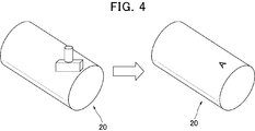
- the shape of the marking portion is an alphabet “A”.
- a concave portion or a convex portion having a complementary dimensional shape is provided in order to transfer the convex portion and the concave portion to the surface of the molded body.
- a transfer area is formed, and a marking portion is provided in the transfer area.
- the height of the concave portion of the marking portion is substantially the same as the height of the concave portion of the other part of the transfer region. It is formed so as to be lower than the height of the convex part of the other part of the transfer region.
- the height of the convex portion of the concavo-convex structure of the molded body to which the fine concavo-convex structure of the mold is transferred is substantially the same over the surface of the molded body. It becomes possible to easily manufacture a molded body that is higher than the height of the concave portion in the region where the concave portion is formed. Since the tops of the concavo-convex structure have substantially the same height across the surface of the molded body, the occurrence of defects such as dents is suppressed even when the molded body is wound into a roll.
- the height of the concave part is higher than the height of the concave part in the area where the other concave part is formed, and the reflectance and transmittance of light are different from other areas. It becomes possible to identify.
- the method for producing a molded product having a fine concavo-convex structure on the surface thereof according to the present invention comprises a fine concavo-convex structure comprising a plurality of pores formed on the surface of a mold obtained by the mold production method of the present invention. It is the method of transferring to the surface of the.
- the molded product produced by transferring the fine concavo-convex structure (pores) of the mold has the inverted structure (protrusions) of the fine concavo-convex structure of the mold transferred on the surface due to the relationship between the key and the keyhole. Is done.
- an uncured active energy ray-curable resin composition is filled between the mold and the transparent substrate (molded body), In a state where the active energy ray-curable resin composition is in contact with the fine concavo-convex structure, a method of releasing the mold after irradiating the active energy ray to cure the active energy ray-curable resin composition is preferable.
- cured material of an active energy ray curable resin composition was formed in the surface of a transparent base material can be manufactured.
- the fine concavo-convex structure of the obtained molded body is an inverted structure of the fine concavo-convex structure of the mold.
- polyester resin polyethylene terephthalate, polybutylene terephthalate, etc.
- polymethacrylate resin polycarbonate resin, vinyl chloride resin, ABS resin, styrene resin, glass and the like.
- the fine uneven structure can be transferred in a short time, Suitable for mass production.
- a method of filling the active energy ray curable resin composition a method of supplying the active energy ray curable resin composition between the mold and the transparent substrate and then rolling and filling the active energy ray curable resin composition, Examples thereof include a method of laminating a transparent substrate on the applied mold, a method of previously applying an active energy ray-curable resin composition on a transparent substrate, and laminating the mold on the mold.
- the active energy ray-curable resin composition contains a polymerization reactive compound and an active energy ray polymerization initiator.
- a non-reactive polymer or active energy ray sol-gel reactive component may be contained depending on the application, and a thickener, leveling agent, ultraviolet absorber, light stabilizer, heat stabilizer, solvent Various additives such as inorganic fillers may be included.
- polymerization reactive compound examples include monomers, oligomers, and reactive polymers having a radical polymerizable bond and / or a cationic polymerizable bond in the molecule.
- monomer having a radical polymerizable bond examples include a monofunctional monomer and a polyfunctional monomer.
- Monofunctional monomers having radical polymerizable bonds include (meth) acrylate derivatives (methyl (meth) acrylate, ethyl (meth) acrylate, propyl (meth) acrylate, n-butyl (meth) acrylate, i-butyl (meth) Acrylate, s-butyl (meth) acrylate, t-butyl (meth) acrylate, 2-ethylhexyl (meth) acrylate, lauryl (meth) acrylate, alkyl (meth) acrylate, tridecyl (meth) acrylate, stearyl (meth) acrylate, Cyclohexyl (meth) acrylate, benzyl (meth) acrylate, phenoxyethyl (meth) acrylate, isobornyl (meth) acrylate, glycidyl (meth) acrylate, tetrahydrofurfuryl (
- bifunctional monomers ethylene glycol di (meth) acrylate, tripropylene glycol di (meth) acrylate, isocyanuric acid ethylene oxide modified di (meth) acrylate, triethylene glycol di) (Meth) acrylate, diethylene glycol di (meth) acrylate, neopentyl glycol di (meth) acrylate, 1,6-hexanediol di (meth) acrylate, 1,5-pentanediol di (meth) acrylate, 1,3-butylene Glycol di (meth) acrylate, polybutylene glycol di (meth) acrylate, 2,2-bis (4- (meth) acryloxypolyethoxyphenyl) propane, 2,2-bis (4- (meth) acryloxyethoxy) Enyl) propane, 2,2-bis (4- (3- (meth) acryloxy-2-hydroxypropoxy) phenyl) propane
- Examples of the monomer having a cationic polymerizable bond include monomers having an epoxy group, an oxetanyl group, an oxazolyl group, a vinyloxy group, and the like, and a monomer having an epoxy group is particularly preferable.
- Examples of the oligomer or reactive polymer having a radical polymerizable bond and / or a cationic polymerizable bond in the molecule include unsaturated polyesters such as a condensate of unsaturated dicarboxylic acid and polyhydric alcohol; polyester (meth) acrylate, poly Ether (meth) acrylate, polyol (meth) acrylate, epoxy (meth) acrylate, urethane (meth) acrylate, cationic polymerization type epoxy compound, homopolymer or copolymer of the above-mentioned monomers having a radical polymerizable bond in the side chain, etc. Can be mentioned.
- the active energy ray polymerization initiator a known polymerization initiator can be used, and it is preferable to select appropriately according to the type of the active energy ray used when the active energy ray curable resin composition is cured.
- photoinitiators When using a photocuring reaction, photoinitiators include carbonyl compounds (benzoin, benzoin methyl ether, benzoin ethyl ether, benzoin isopropyl ether, benzoin isobutyl ether, benzyl, benzophenone, p-methoxybenzophenone, 2,2-di- Ethoxyacetophenone, ⁇ , ⁇ -dimethoxy- ⁇ -phenylacetophenone, methylphenylglyoxylate, ethylphenylglyoxylate, 4,4′-bis (dimethylamino) benzophenone, 2-hydroxy-2-methyl-1-phenylpropane -1-one, etc.), sulfur compounds (tetramethylthiuram monosulfide, tetramethylthiuram disulfide, etc.), 2,4,6-trimethylbenzoyldiphenylphosphine oxide, bis (2, , 6-trimethyl benzoyl) -
- polymerization initiators include benzophenone, 4,4-bis (diethylamino) benzophenone, 2,4,6-trimethylbenzophenone, methyl orthobenzoylbenzoate, 4-phenylbenzophenone, t-butylanthraquinone 2-ethylanthraquinone, thioxanthone (2,4-diethylthioxanthone, isopropylthioxanthone, 2,4-dichlorothioxanthone, etc.), acetophenone (diethoxyacetophenone, 2-hydroxy-2-methyl-1-phenylpropan-1-one, Benzyldimethyl ketal, 1-hydroxycyclohexyl-phenylketone, 2-methyl-2-morpholino (4-thiomethylphenyl) propan-1-one, 2-benzyl-2-dimethylamino-1- ( -Morpholinophenyl) -butanone), benzophenone, 4,4-bis
- the content of the active energy ray polymerization initiator in the active energy ray-curable resin composition is preferably 0.1 to 10 parts by mass with respect to 100 parts by mass of the polymerizable compound.
- the active energy ray polymerization initiator is less than 0.1 part by mass, the polymerization is difficult to proceed.
- the active energy ray polymerization initiator exceeds 10 parts by mass, the cured resin may be colored or the mechanical strength may be lowered.
- non-reactive polymers examples include acrylic resins, styrene resins, polyurethane resins, cellulose resins, polyvinyl butyral resins, polyester resins, and thermoplastic elastomers.
- Examples of the active energy ray sol-gel reactive composition include alkoxysilane compounds and alkyl silicate compounds.
- alkoxysilane compound examples include those represented by RxSi (OR ′) y.
- tetramethoxysilane tetra-iso-propoxysilane, tetra-n-propoxysilane, tetra-n-butoxysilane, tetra-sec-butoxysilane, tetra-tert-butoxysilane, methyltriethoxysilane, methyl
- tripropoxysilane methyltributoxysilane, dimethyldimethoxysilane, dimethyldiethoxysilane, trimethylethoxysilane, trimethylmethoxysilane, trimethylpropoxysilane, and trimethylbutoxysilane.
- alkyl silicate compound examples include those represented by R1O [Si (OR3) (OR4) O] zR2.
- R1 to R4 each represents an alkyl group having 1 to 5 carbon atoms, and z represents an integer of 3 to 20. Specific examples include methyl silicate, ethyl silicate, isopropyl silicate, n-propyl silicate, n-butyl silicate, n-pentyl silicate, acetyl silicate and the like.
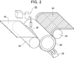
- a molded body having a fine concavo-convex structure on its surface is manufactured as follows using, for example, a manufacturing apparatus shown in FIG.
- the active energy ray-curable resin composition 38 is supplied from the tank 22 to the belt-shaped film 42 (transparent substrate) that moves in the direction of the film.
- the film 42 and the active energy ray-curable resin composition 38 are nipped between the roll-shaped mold 20 and the nip roll 26 whose nip pressure is adjusted by a pneumatic cylinder, and the active energy ray-curable resin composition 38 is 42 and the roll-shaped mold 20 are spread uniformly, and at the same time, the recesses of the fine concavo-convex structure of the roll-shaped mold 20 are filled.
- the active energy ray curable resin composition 38 is irradiated through the film 42 from the active energy ray irradiation device 28 installed below the roll-shaped mold 20 to cure the active energy ray curable resin composition 38.
- the cured resin layer 44 to which the fine uneven structure on the surface of the roll-shaped mold 20 is transferred is formed.
- the peeled roll 30 peels the film 42 having the cured resin layer 44 formed on the surface from the roll-shaped mold 20 to obtain a molded body 40 as shown in FIG.
- the film 42 peeled from the roll-shaped mold 20 is taken up by a take-up roll (not shown), and thus a film 42 having a fine uneven structure on the surface is obtained.
- Examples of the active energy ray irradiation device 28 include a high-pressure mercury lamp and a metal halide lamp.
- the irradiation amount of the active energy ray may be an energy amount that allows the active energy ray-curable resin composition to cure, and is usually about 100 to 10,000 mJ / cm 2 .
- the molded body 40 manufactured in this way has a cured resin layer 44 formed on the surface of a film 42 (transparent substrate).
- the cured resin layer 44 is a film made of a cured product of the active energy ray curable resin composition, and has a fine uneven structure on the surface.
- the fine uneven structure on the surface of the molded body 40 is formed by transferring the fine uneven structure on the surface of the oxide film, and is an active energy ray-curable resin composition. And a plurality of protrusions 46 made of a cured product.
- the fine concavo-convex structure is preferably a so-called moth-eye structure in which a plurality of protrusions (convex portions) having a substantially conical shape or a pyramid shape are arranged. It is known that the moth-eye structure in which the distance between the protrusions is less than or equal to the wavelength of visible light is an effective anti-reflection measure by continuously increasing the refractive index from the refractive index of air to the refractive index of the material. It has been.
- a marking portion having a surface shape including at least one of a letter, a number, a geometric shape, a geometric pattern, and an identification symbol is formed on the molded body, and the height of the top portion of the protrusion 46 of the marking portion is set in another region.
- the height of the concave portion (valley portion) is higher than the height of the concave portion in the region where the other concave portion is formed.
- the difference between the height of the concave portion in the marking portion and the height of the concave portion in the region where the other concave portion is formed is preferably 10 nm or more, more preferably 20 nm or more, and further preferably 40 nm or more. preferable.
- the tops of the concavo-convex structure of the molded body have substantially the same height, the occurrence of defects such as dents is suppressed even when the molded body is rolled up.
- the height of the bottom of the concave portion is higher than the height of the concave portion in the region where the other concave portion is formed, and the reflectance and transmittance of light are different from other regions. It is possible to easily identify the marking portion. If it is easy to identify the marking part, if a defect is found by inspecting the molded body, it is easily inspected whether a specific part of the mold contains a defect from the relative positional relationship with the marking part. be able to.
- the molded body having a fine concavo-convex structure on the surface is in the form of a sheet or film, as an antireflection film, for example, an object such as an image display device (TV, mobile phone display, etc.), display panel, meter panel, etc. It can be used by sticking to the surface or insert molding.
- an object such as an image display device (TV, mobile phone display, etc.), display panel, meter panel, etc. It can be used by sticking to the surface or insert molding.
- it can also be used as a member for objects that may be exposed to rain, water, steam, etc., such as bathroom windows and mirrors, solar cell members, automobile mirrors, signboards, and glasses lenses. Can be used.
- an antireflection article is manufactured using a transparent substrate having a shape according to the application, and this is used as a member constituting the surface of the object. It can also be used.
- the object when the object is an image display device, not only the surface thereof but also a molded body having a fine uneven structure on the surface may be attached to the front plate, or the front plate itself may be It can also be comprised from the molded object which has an uneven
- the surface of a rod lens array attached to a sensor array that reads an image, a cover glass of an image sensor such as a FAX, a copying machine, or a scanner, or a contact glass on which a document of a copying machine is placed has a fine uneven structure on the surface.
- the body may be used.
- a molded body having a fine concavo-convex structure on the surface of a light receiving portion of an optical communication device such as visible light communication signal reception sensitivity can be improved.
- the molded product having a fine concavo-convex structure on the surface can be developed for optical uses such as optical waveguides, relief holograms, optical lenses, and polarization separation elements, and for use as a cell culture sheet.
- Each cross-sectional sample was observed at a magnification of 50,000 times, and the depths of 10 pores were measured and averaged within the observation range. This measurement was performed at two points, and the average value of each observation point was further averaged to determine the average depth of the pores.
- the surface of the molded body was observed at a magnification of 10,000 times, and the average distance (pitch) between the protrusions was calculated by averaging the distances between the centers of the six protrusions (convex parts) arranged in a straight line. Moreover, the cross section of the molded body was observed at 50,000 times, and the average height of the protrusions was obtained by averaging the heights of the ten protrusions.
- the viscosity is measured with a rheometer (AR Instruments AR550) using a 60 mm cone plate at a temperature of 20 ° C. and a shear rate of 0.1 to 1000 (1 / s). The value at which the viscosity did not change with respect to the shear rate was taken as the viscosity of the present invention.
- Example 1 Lump-like aluminum having a purity of 99.97% by mass was cut into a roll having a diameter of 200 mm and a width of 320 mm, and the surface was cut into a mirror surface, which was used as an aluminum substrate.
- Table 1 shows the material of the base material.
- Al is aluminum
- 3N7 represents the purity of aluminum, which means a purity of 99.97% by mass.
- the aluminum substrate was anodized in a 0.3 M oxalic acid aqueous solution for 6 hours under the conditions of a direct current of 40 V and a temperature of 16 ° C. (step (a)).
- the aluminum plate on which the oxide film was formed was immersed in a 6% by mass phosphoric acid / 1.8% by mass chromic acid mixed aqueous solution for 6 hours to remove the oxide film (step (b)).
- the aluminum substrate was anodized in a 0.3 M oxalic acid aqueous solution under conditions of a direct current of 40 V and a temperature of 16 ° C. for 20 seconds (step (c)).
- the aluminum base material on which the oxide film was formed was immersed in a 5% by mass phosphoric acid aqueous solution at 32 ° C. for 8 minutes to carry out pore size expansion treatment (step (d)).
- step (c) and the step (d) are repeated four times in total, and finally the step (d) is performed (step (e)), and the substantially conical pores having an average interval of 100 nm and a depth of 220 nm are obtained.
- Anodized alumina having a surface was formed on the surface.
- phosphoric acid having a concentration of 85% (viscosity 47 cP) was impregnated into the ben cotton, and the rubber stamp was pressed against the ben cotton to press the rubber stamp with the phosphoric acid against the surface of the anodized alumina for marking.
- the marked part was washed with water, phosphoric acid was removed to form a marking part (step (f)), and a roll-shaped mold was obtained.
- a marking portion was formed.
- the obtained mold was immersed in a 0.1% by weight diluted solution of OPTOOL DSX (manufactured by Daikin Chemicals Sales Co., Ltd.) and then air-dried overnight to obtain a roll-shaped mold treated with a release agent. It was.
- An active energy ray-curable resin composition having the following composition is filled between a mold subjected to a mold release treatment and an acrylic film (Mitsubishi Rayon Co., Ltd., “Acryprene HBS010”), which is a transparent substrate, and high-pressure mercury
- the active energy ray-curable resin composition was cured by irradiating the lamp with ultraviolet rays having an integrated light quantity of 1000 mJ / cm 2 . Thereafter, the mold was peeled off to obtain a molded body (film) composed of a transparent substrate and a cured product of the cured composition.
- a fine concavo-convex structure was formed on the surface of the molded body thus produced, and the average interval (pitch) between the protrusions was 100 nm, and the average height of the protrusions was about 220 nm. Moreover, although a molded object was wound up in roll shape, winding wrinkles, dents, etc. did not generate
- Active energy ray-curable resin composition Dipentaerythritol hexaacrylate (manufactured by Shin-Nakamura Chemical Co., Ltd.): 25 parts by mass Pentaerythritol triacrylate (Daiichi Kogyo Seiyaku Co., Ltd.): 25 parts by mass, Ethylene oxide modified dipentaerythritol hexaacrylate (manufactured by Nippon Kayaku Co., Ltd.): 25 parts by mass Polyethylene glycol diacrylate (manufactured by Toagosei Co., Ltd.): 25 parts by mass, 1-hydroxycyclohexyl phenyl ketone (manufactured by BASF): 1 part by mass, Bis (2,4,6-trimethylbenzoyl) -phenylphosphine oxide (BASF): 0.5 parts by mass Polyoxyethylene alkyl (12-15) ether phosphoric acid (manufactured by Nippon Chemical Co
- Example 2 (Examples 2 to 5)
- step (f) a molded body was produced and visually molded in the same manner as in Example 1 except that the concentration of phosphoric acid soaked into Bencotton and the time for standing after pressing the rubber stamp were set as shown in Table 1. The body was observed. The results are shown in Table 1.
- Example 1 A molded body was produced in the same manner as in Example 1 except that the step (f) was not performed. Moreover, although the mark was given with the oil-based pen near the edge part of a molded object, marking disappeared by wiping off with ethanol.
- Example 3 A molded body was produced in the same manner as in Example 1 except that the mold surface was scratched with a file instead of the step (f). When this compact was wound into a roll, it was wrinkled.
Landscapes
- Physics & Mathematics (AREA)
- Engineering & Computer Science (AREA)
- Mechanical Engineering (AREA)
- General Physics & Mathematics (AREA)
- Optics & Photonics (AREA)
- Chemical & Material Sciences (AREA)
- Chemical Kinetics & Catalysis (AREA)
- Shaping Of Tube Ends By Bending Or Straightening (AREA)
- Moulds For Moulding Plastics Or The Like (AREA)
- Surface Treatment Of Optical Elements (AREA)
Abstract
Description
また、「細孔の間隔」とは、隣接する細孔同士の中心間距離を意味する。
また、「突起」とは、成形体の表面に形成された微細凹凸構造の凸部のことをいう。
また、「微細凹凸構造」は、隣接する凸部および隣接する凹部の平均間隔が10~400nmである構造を意味する。
また、「凸部の高さ」は、型や成形体の表面に形成された微細凹凸構造の凹部の最深部同士をつなぐ面を基準とした、凸部の頂部の高さを意味する。例えば、図3においてh1やh2が凸部の高さを示している。
また、「凹部の高さ」は、型や成形体の表面に形成された微細凹凸構造の凹部の最深部同士をつなぐ面を基準とした、凹部の底部の高さを意味する。例えば、図3においてh0や、h0’、h3が凹部の高さを示している。
また、「(メタ)アクリレート」は、アクリレートおよびメタクリレートの総称である。
また、「活性エネルギー線」は、可視光線、紫外線、電子線、プラズマ、熱線(赤外線等)等を意味する。
モールド(型)に微細凹凸構造を形成する方法は特に限定されないが、その具体例としては、電子ビームリソグラフィー法、レーザー光干渉法などが挙げられる。例えば、適当な支持基板上に適当なフォトレジスト膜を塗布し、紫外線レーザー、電子線、X線等の光で露光し、現像することによって微細凹凸構造を形成した型を得て、この型をそのままマザーモールドとして使用することもできる。また、フォトレジスト層を介して支持基板をドライエッチングにより選択的にエッチングし、前記レジスト層を除去することで支持基板そのものに直接微細凹凸構造を形成することも可能である。
また、陽極酸化ポーラスアルミナをモールドとして利用することも可能である。陽極酸化ポーラスアルミナとしては、例えば、アルミニウムをシュウ酸、硫酸、リン酸等を電解液として所定の電圧にて陽極酸化することにより形成される微細凹凸構造をモールドとして利用してもよい。以下に、陽極酸化ポーラスアルミナをモールドとして利用する場合の具体例を説明する。
(a)機械加工されたアルミニウム基材に電圧を印加し、前記アルミニウム基材の表面を陽極酸化して酸化皮膜を形成する工程。
(b)前記工程(a)で形成された酸化皮膜の少なくとも一部を除去する工程。
(c)前記工程(b)または下記工程(d)の後、アルミニウム基材を陽極酸化して、複数の細孔を有する酸化皮膜を形成する工程。
(d)前記工程(c)の後、細孔の孔径を拡大する工程。
(e)前記工程(c)と前記工程(d)とを交互に繰り返す工程。
(f)酸化皮膜の一部を溶解し、モールド上にマーキング部を形成する工程。
工程(a)は、機械加工されたアルミニウム基材に電圧を印加し、前記アルミニウム基材の表面を陽極酸化して酸化皮膜を形成する第一の酸化皮膜形成工程である。
工程(a)を行うと、例えば図1に示すように、アルミニウム基材10の表面に複数の細孔12を有する酸化皮膜14が形成される。
アルミニウム基材としては、機械加工されたものを用いる。
本発明において「機械加工」とは、アルミニウム基材の表面を物理的に切削または研磨して、電解研磨することなく鏡面化することである。なお、物理的な研磨には「テープ研磨」も含まれる。
シュウ酸の濃度は、0.7M以下が好ましい。シュウ酸の濃度が0.7Mを超えると、電流値が高くなりすぎて酸化皮膜の表面が粗くなることがある。
電解液の温度は、60℃以下が好ましく、45℃以下がより好ましい。電解液の温度が60℃を超えると、いわゆる「ヤケ」といわれる現象がおこり、細孔が壊れたり、表面が溶けて細孔の規則性が乱れたりすることがある。
硫酸の濃度は0.7M以下が好ましい。硫酸の濃度が0.7Mを超えると、電流値が高くなりすぎて定電圧を維持できなくなることがある。
電解液の温度は、30℃以下が好ましく、20℃以下がより好ましい。電解液の温度が30℃を超えると、いわゆる「ヤケ」といわれる現象がおこり、細孔が壊れたり、表面が溶けて細孔の規則性が乱れたりすることがある。
図1に示すように、酸化皮膜14の少なくとも一部を一旦除去し、これを陽極酸化の細孔発生点16にすることで細孔の規則性を向上することができる。
図1に示すように、酸化皮膜の少なくとも一部を除去したアルミニウム基材10を再度、陽極酸化すると、円柱状の細孔12を有する酸化皮膜14が形成される。
陽極酸化は、工程(a)と同様な条件で行うことにより、高い規則性を有する細孔を得ることができるが、陽極酸化の条件は種々に変更してもよい。陽極酸化の時間を長くするほど深い細孔を得ることができる。
図1に示すように、細孔12の径を拡大させる処理(以下、細孔径拡大処理と記す。)を行う。細孔径拡大処理は、酸化皮膜を溶解する溶液(エッチング液)に浸漬して陽極酸化で得られた細孔の径を拡大させる処理である。このような溶液としては、例えば、5質量%程度のリン酸水溶液等が挙げられる。
細孔径拡大処理の時間を長くするほど、細孔径は大きくなる。
図1に示すように、工程(c)の陽極酸化と、工程(d)の細孔径拡大処理とを繰り返すと、直径が開口部から深さ方向に連続的に減少する形状の細孔12を有する酸化皮膜14が形成され、アルミニウム基材10の表面に陽極酸化アルミナ(アルミニウムの多孔質の酸化皮膜(アルマイト))を有するモールド18が得られる。最後は工程(d)で終わることが好ましい。
細孔12間の平均間隔は、電子顕微鏡観察によって隣接する細孔12間の間隔(細孔12の中心から隣接する細孔12の中心までの距離)を50点測定し、これらの値を平均したものである。
細孔12間の平均間隔は、可視光の波長以下、すなわち400nm以下である。細孔12間の平均間隔は、20nm以上が好ましい。
細孔12のアスペクト比(細孔の深さ/細孔間の平均間隔)は、0.8~5.0が好ましく、1.2~4.0がより好ましく、1.5~3.0が特に好ましい。
具体的には、例えば細孔間の平均間隔が100nmの場合は、細孔12の深さは80~500nmが好ましく、120~400nmがより好ましく、150~300nmが特に好ましい。
ついで、図1に示すように、微細凹凸構造が形成された領域(転写部)に、マーキング部を形成する。マーキング部は、陽極酸化皮膜を溶解することのできるマーキング溶液と、陽極酸化皮膜とを所定時間接触させて酸化皮膜の一部を溶解することで微細凹凸構造の一部の凸部の高さを変化させ、その後マーキング溶液を洗浄等で除去することで形成される。
以上説明した本発明のモールドの製造方法にあっては、工程(f)において、成形体の表面に凸部および凹部を転写するため、相補的な寸法形状を有する凹部又は凸部が設けられた転写領域が形成され、この転写領域には、マーキング部が設けられ、このマーキング部は凹部の高さが転写領域の他の部分の凹部の高さと略同一であるが、凸部の高さが転写領域の他の部分の凸部の高さよりも低くなるように形成される。このモールドを用いれば、モールドの微細凹凸構造が転写された成形体の凹凸構造の凸部の高さは成形体の表面にわたって略同一であるが、マーキング部では凹凸構造の凹部の高さが他の凹部が形成された領域の凹部の高さよりも高くなった成形体を容易に製造することが可能となる。成形体の表面にわたって凹凸構造の頂部が略同一の高さであるために、成形体をロール状に巻き取った際にも、打痕などの欠陥が発生することが抑制される。また、成形体のマーキング部では凹部の高さが他の凹部が形成された領域の凹部の高さよりも高く、他の領域と光の反射率や透過率が異なるために、容易にマーキング部を識別することが可能となる。
本発明の、微細凹凸構造を表面に有する成形体の製造方法は、本発明のモールドの製造方法で得られたモールドの表面に形成された複数の細孔からなる微細凹凸構造を、成形体本体の表面に転写する方法である。
透明基材としては、活性エネルギー線の照射を、該透明基材を介して行うため、活性エネルギー線の照射を著しく阻害しないものが好ましい。透明基材の材料としては、例えば、ポリエステル樹脂(ポリエチレンテレフタレート、ポリブチレンテレフタレート等)、ポリメタクリレート樹脂、ポリカーボネート樹脂、塩化ビニル樹脂、ABS樹脂、スチレン樹脂、ガラス等が挙げられる。
活性エネルギー線硬化性樹脂組成物を用いる方法は、熱硬化性樹脂組成物を用いる方法に比べて加熱や硬化後の冷却を必要としないため、短時間で微細凹凸構造を転写することができ、量産に好適である。
活性エネルギー線硬化性樹脂組成物の充填方法としては、モールドと透明基材の間に活性エネルギー線硬化性樹脂組成物を供給した後に圧延して充填する方法、活性エネルギー線硬化性樹脂組成物を塗布したモールド上に透明基材をラミネートする方法、あらかじめ透明基材上に活性エネルギー線硬化性樹脂組成物を塗布してモールドにラミネートする方法等が挙げられる。
ラジカル重合性結合を有するモノマーとしては、単官能モノマー、多官能モノマーが挙げられる。
微細凹凸構造を表面に有する成形体は、例えば、図2に示す製造装置を用いて、下記のようにして製造される。
このようにして製造された成形体40は、図3に示すように、フィルム42(透明基材)の表面に硬化樹脂層44が形成されたものである。硬化樹脂層44は、活性エネルギー線硬化性樹脂組成物の硬化物からなる膜であり、表面に微細凹凸構造を有する。
本発明により得られた、微細凹凸構造を表面に有する成形体は、表面の微細凹凸構造によって、反射防止性能、撥水性能等の種々の性能を発揮する。
酸化皮膜が表面に形成されたモールドの一部を切り取って、表面に白金を1分間蒸着し、電解放出型走査電子顕微鏡(日本電子株式会社製、「JSM-6701F」)を用いて、加速電圧3.00kVで1万倍に拡大して観察した。細孔の平均間隔(ピッチ)は一直線上に並んだ6個の細孔の中心間距離を平均して求めた。
また、モールドの一部を異なる2箇所から切り取って、その縦断面に白金を1分間蒸着し、同じく電解放出型走査電子顕微鏡を用いて加速電圧3.00kVで観察した。各断面サンプルを5万倍に拡大して観察し、観察範囲で10個の細孔の深さを測定し、平均した。この測定を2点で行い、各観察点の平均値をさらに平均して細孔の平均深さを求めた。
成形体(フィルム)の表面および縦断面に白金を10分間蒸着し、電解放出型走査電子顕微鏡(日本電子株式会社製、「JSM-6701F」)を用いて、加速電圧3.00kVの条件で成形体の表面および断面を観察した。
粘度の測定には、レオメーター(ティー・エイ・インスツルメント社製 AR550)にて、60mmのコーンプレートを用いて、温度20℃、せん断速度を0.1~1000(1/s)の範囲で測定を行い、せん断速度に対して粘度が変化しない値を本発明の粘度とした。
成形体を目視で観察し、マーキング部が容易に識別できる場合を○、注意しながら観察すると識別できる場合を△、識別が困難な場合を×とした。
(モールドの製造)
純度99.97質量%の塊状アルミニウムを直径200mm、幅320mmのロール状に切断し、表面を切削加工して鏡面化し、これをアルミニウム基材として用いた。基材の材質を表1に示す。なお、表中の「Al」はアルミニウムであり、「3N7」はアルミニウムの純度を表し、純度99.97質量%を意味する。
該アルミニウム基材について、0.3Mシュウ酸水溶液中で、直流40V、温度16℃の条件で6時間陽極酸化を行った(工程(a))。
ついで、酸化皮膜が形成されたアルミニウム板を、6質量%リン酸/1.8質量%クロム酸混合水溶液に6時間浸漬して、酸化皮膜を除去した(工程(b))。
ついで、該アルミニウム基材について、0.3Mシュウ酸水溶液中、直流40V、温度16℃の条件で20秒間陽極酸化を行った(工程(c))。
ついで、酸化皮膜が形成されたアルミニウム基材を、32℃の5質量%リン酸水溶液に8分間浸漬して、細孔径拡大処理を行った(工程(d))。
ついで、前記工程(c)および工程(d)を合計で4回繰り返し、最後に工程(d)を行い(工程(e))、平均間隔:100nm、深さ:220nmの略円錐形状の細孔を有する陽極酸化アルミナを表面に形成した。
ついで、濃度85%(粘度47cP)のリン酸をベンコットンに染み込ませ、ゴム印をベンコットンに押しつけてリン酸を付けたゴム印を、陽極酸化アルミナの表面に押しつけて、マーキングを施した。20分間静置した後、マーキングを施した部位を水洗しリン酸を除去しマーキング部を形成し(工程(f))、ロール状モールドを得た。目視で確認したところ、マーキング部が形成されていることが確認された。
得られた金型を、オプツールDSX(ダイキン化成品販売社製)の0.1質量%希釈溶液に浸漬した後、一晩風乾して、離型剤で処理されたロール状の金型を得た。
離型処理したモールドと、透明基材であるアクリルフィルム(三菱レイヨン株式会社製、「アクリプレン HBS010」)との間に、下記の組成の活性エネルギー線硬化性樹脂組成物を充填して、高圧水銀ランプで積算光量1000mJ/cm2の紫外線を照射することによって、活性エネルギー線硬化性樹脂組成物を硬化させた。その後、モールドを剥離し、透明基材と硬化組成物の硬化物からなる成形体(フィルム)を得た。
このようにして製造した成形体の表面には微細凹凸構造が形成されており、突起の平均間隔(ピッチ)は100nm、突起の平均高さは約220nmであった。また、ロール状に成形体を巻き取ったが、巻きジワや打痕等は発生しなかった。
得られた成形体を目視で観察し、マーキング部の確認を行った。その結果を表1に示す。
ジペンタエリスリトールヘキサアクリレート(新中村化学工業株式会社製):25質量部、
ペンタエリスリトールトリアクリレート(第一工業製薬株式会社製):25質量部、
エチレンオキサイド変性ジペンタエリスリトールヘキサアクリレート(日本化薬株式会社製):25質量部、
ポリエチレングリコールジアクリレート(東亞合成株式会社製):25質量部、
1-ヒドロキシシクロヘキシルフェニルケトン(BASF社製):1質量部、
ビス(2,4,6-トリメチルベンゾイル)-フェニルフォスフィンオキサイド(BASF社製):0.5質量部、
ポリオキシエチレンアルキル(12~15)エーテルリン酸(日本ケミカルズ株式会社製):0.1質量部。
工程(f)において、ベンコットンにしみこませるリン酸の濃度、ゴム印を押しつけた後に静置する時間を表1の様にした以外は実施例1と同様に、成形体を製造し、目視で成形体を観察した。その結果を表1に示す。

工程(f)を行わなかった以外は、実施例1と同様に成形体を製造した。また、成形体の端部近傍に油性ペンでマークを施したが、エタノールで拭取ることによりマーキングが消えてしまった。
成形体にマーキングとしてヤスリでフィルム搬送方向に傷をつけた。この成形体をロール状に巻き取ると巻きシワになった。
工程(f)の代わりに、ヤスリでモールド表面に傷をつけた以外は、実施例1と同様に成形体を製造した。この成形体をロール状に巻き取ると巻きシワになった。
12 細孔
14 酸化皮膜
16 細孔発生点
18 モールド(型)
20 ロール状モールド
22 タンク
26 ニップロール
28 活性エネルギー線照射装置
30 剥離ロール
38 活性エネルギー線硬化性樹脂組成物
40 成形体
42 フィルム
44 硬化樹脂層
46 突起
Claims (13)
- 表面に周期が可視光の波長以下である複数の凸部と、隣接する該凸部の間に形成された複数の凹部とを有する光学物品の製造に用いられる型であって、前記型は、表面に前記光学物品の凸部および凹部と相補的な寸法形状を有する凹部および凸部が設けられた転写領域を有し、前記転写領域には、マーキング部が設けられ、前記凸部の高さが転写領域の他の部分の凸部の高さよりも低いことを特徴とする、光学物品の製造に用いられる型。
- 前記マーキング部は、文字、幾何学形状、幾何学模様、識別記号の少なくとも一つを含む表面形状を有している、請求項1に記載の型。
- 外形がロール形状であることを特徴とする、請求項1に記載の型。
- 表面に周期が可視光の波長以下である複数の凸部と、隣接する該凸部の間に形成された複数の凹部と、を有する光学物品であって、
該光学物品はマーキング部を有し、前記凹部の高さが他の凹部が形成された領域の凹部の高さよりも高いことを特徴とする光学物品。 - 前記マーキング部は、文字、数字、幾何学形状、幾何学模様、識別記号の少なくとも一つを含む表面形状を有している、請求項4に記載の光学物品。
- 表面に周期が可視光の波長以下である複数の凸部と、隣接する該凸部の間に形成された複数の凹部とを有する型の製造方法であって、前記型の表面に、前記凸部および前記凹部を形成する凹凸形成工程と、前記凸部および前記凹部が形成された領域の一部分を、前記型を溶解する液体と接触させ、前記凸部の高さを前記凹凸形成工程で形成された凸部の高さよりも低くするマーキング工程とを有することを特徴とする、型の製造方法。
- 前記凹凸形成工程は、アルミニウム母材を陽極酸化し、前記アルミニウム母材の表面に微細凹構造を形成する陽極酸化処理、および前記微細凹構造をエッチング液と接触させ、前記微細凹構造の口径を拡大する拡大処理を含む、請求項6に記載の型の製造方法。
- 前記マーキング工程で用いられる液体と、前記拡大処理に用いられるエッチング液とが同一の組成であることを特徴とする、請求項7に記載の型の製造方法。
- 前記マーキング工程で用いられる液体と前記エッチング液とが、リン酸を含むことを特徴とする、請求項7に記載の型の製造方法。
- 前記マーキング工程で用いられる液体の、20℃における粘度が0.5~5000cPであることを特徴とする、請求項6に記載の型の製造方法。
- 前記マーキング工程で用いられる液体の、20℃における粘度が1~1500cPであることを特徴とする、請求項10に記載の型の製造方法。
- 前記マーキング工程は、前記液体が付着された部材と前記型とを接触させるものである、請求項6乃至11のいずれか1項に記載の型の製造方法。
- 請求項6に記載の方法により製造された、表面に微細凹凸構造を有するロール状モールドの表面の微細凹凸構造を、ロール状モールドの回転に同期してロール状モールドの表面の一部に沿って移動する帯状のフィルム本体の表面に転写して微細凹凸構造を表面に有するフィルムを得、前記フィルムを巻取りロールで巻取ることを特徴とする、微細凹凸構造を表面に有するフィルムの製造装置。
Priority Applications (4)
| Application Number | Priority Date | Filing Date | Title |
|---|---|---|---|
| CN201380068610.9A CN104884218A (zh) | 2012-12-28 | 2013-12-27 | 光学物品、用于制造光学物品的模具和模具的制造方法 |
| US14/655,502 US9523796B2 (en) | 2012-12-28 | 2013-12-27 | Optical article, mold used in production of optical article, and mold production method |
| JP2014503885A JP6252990B2 (ja) | 2012-12-28 | 2013-12-27 | 光学物品の製造に用いられる型の製造方法及びこの型を用いた光学物品の製造装置 |
| KR1020157016959A KR20150088864A (ko) | 2012-12-28 | 2013-12-27 | 광학 물품, 광학 물품의 제조에 이용되는 형 및 형의 제조 방법 |
Applications Claiming Priority (2)
| Application Number | Priority Date | Filing Date | Title |
|---|---|---|---|
| JP2012-287568 | 2012-12-28 | ||
| JP2012287568 | 2012-12-28 |
Publications (1)
| Publication Number | Publication Date |
|---|---|
| WO2014104308A1 true WO2014104308A1 (ja) | 2014-07-03 |
Family
ID=51021377
Family Applications (1)
| Application Number | Title | Priority Date | Filing Date |
|---|---|---|---|
| PCT/JP2013/085135 Ceased WO2014104308A1 (ja) | 2012-12-28 | 2013-12-27 | 光学物品、光学物品の製造に用いられる型及び型の製造方法 |
Country Status (6)
| Country | Link |
|---|---|
| US (1) | US9523796B2 (ja) |
| JP (1) | JP6252990B2 (ja) |
| KR (1) | KR20150088864A (ja) |
| CN (1) | CN104884218A (ja) |
| TW (1) | TW201433436A (ja) |
| WO (1) | WO2014104308A1 (ja) |
Cited By (5)
| Publication number | Priority date | Publication date | Assignee | Title |
|---|---|---|---|---|
| WO2016027827A1 (ja) * | 2014-08-21 | 2016-02-25 | シャープ株式会社 | 型および型の製造方法 |
| JP2017216444A (ja) * | 2016-05-31 | 2017-12-07 | ナガセケムテックス株式会社 | エッチング液 |
| JP2018044973A (ja) * | 2016-09-12 | 2018-03-22 | Jxtgエネルギー株式会社 | 光学位相差部材の製造方法 |
| US11040471B2 (en) | 2018-06-22 | 2021-06-22 | Canon Kabushiki Kaisha | Resin product, electronic device, and method of making resin product |
| JP2025036467A (ja) * | 2020-09-30 | 2025-03-14 | デクセリアルズ株式会社 | 光学フィルムおよび光学フィルムの製造方法 |
Families Citing this family (4)
| Publication number | Priority date | Publication date | Assignee | Title |
|---|---|---|---|---|
| US20150241603A1 (en) * | 2012-06-22 | 2015-08-27 | Sharp Kabushiki Kaisha | Anti-reflection structure, imprint mold, method for producing anti-reflection structure, method for producing imprint mold, and display device |
| JP6451213B2 (ja) * | 2014-10-30 | 2019-01-16 | 大日本印刷株式会社 | 反射防止物品の製造方法、反射防止物品の賦型用金型の製造方法 |
| CN106842825B (zh) * | 2017-03-21 | 2021-01-12 | 京东方科技集团股份有限公司 | 母模及其制造方法 |
| CN114675358A (zh) * | 2022-04-24 | 2022-06-28 | 福建夜光达科技股份有限公司 | 一种透气钻石花膜及其制备方法 |
Citations (3)
| Publication number | Priority date | Publication date | Assignee | Title |
|---|---|---|---|---|
| JP2007230229A (ja) * | 2006-02-01 | 2007-09-13 | Canon Inc | インプリント用モールド、該モールドによる構造体の製造方法、部材の製造方法 |
| WO2011111697A1 (ja) * | 2010-03-09 | 2011-09-15 | シャープ株式会社 | 陽極酸化層の形成方法、型の製造方法および反射防止膜の製造方法 |
| WO2012124498A1 (ja) * | 2011-03-11 | 2012-09-20 | シャープ株式会社 | 金型、金型の製造方法、及び、ナノインプリントフィルムの製造方法 |
Family Cites Families (6)
| Publication number | Priority date | Publication date | Assignee | Title |
|---|---|---|---|---|
| JPH09304295A (ja) | 1996-05-09 | 1997-11-28 | Sekisui Chem Co Ltd | シート状製品の欠点マーキング装置 |
| JP4343456B2 (ja) | 2001-04-03 | 2009-10-14 | 大日本印刷株式会社 | シート状製品の欠陥マーキング方法および装置 |
| US7690910B2 (en) * | 2006-02-01 | 2010-04-06 | Canon Kabushiki Kaisha | Mold for imprint, process for producing minute structure using the mold, and process for producing the mold |
| JP5569791B2 (ja) | 2010-04-14 | 2014-08-13 | 住友化学株式会社 | 光学フィルム作製用原反フィルム、および光学フィルムの製造方法 |
| JP2011226957A (ja) | 2010-04-21 | 2011-11-10 | Sanritz Corp | 偏光板の欠陥検査方法及び欠陥検査装置 |
| JP2012026863A (ja) | 2010-07-23 | 2012-02-09 | Toray Ind Inc | フィルムの検査装置、検査方法、及び製造方法 |
-
2013
- 2013-12-27 WO PCT/JP2013/085135 patent/WO2014104308A1/ja not_active Ceased
- 2013-12-27 US US14/655,502 patent/US9523796B2/en not_active Expired - Fee Related
- 2013-12-27 TW TW102148580A patent/TW201433436A/zh unknown
- 2013-12-27 KR KR1020157016959A patent/KR20150088864A/ko not_active Ceased
- 2013-12-27 JP JP2014503885A patent/JP6252990B2/ja not_active Expired - Fee Related
- 2013-12-27 CN CN201380068610.9A patent/CN104884218A/zh active Pending
Patent Citations (3)
| Publication number | Priority date | Publication date | Assignee | Title |
|---|---|---|---|---|
| JP2007230229A (ja) * | 2006-02-01 | 2007-09-13 | Canon Inc | インプリント用モールド、該モールドによる構造体の製造方法、部材の製造方法 |
| WO2011111697A1 (ja) * | 2010-03-09 | 2011-09-15 | シャープ株式会社 | 陽極酸化層の形成方法、型の製造方法および反射防止膜の製造方法 |
| WO2012124498A1 (ja) * | 2011-03-11 | 2012-09-20 | シャープ株式会社 | 金型、金型の製造方法、及び、ナノインプリントフィルムの製造方法 |
Cited By (7)
| Publication number | Priority date | Publication date | Assignee | Title |
|---|---|---|---|---|
| WO2016027827A1 (ja) * | 2014-08-21 | 2016-02-25 | シャープ株式会社 | 型および型の製造方法 |
| JPWO2016027827A1 (ja) * | 2014-08-21 | 2017-07-06 | シャープ株式会社 | 型 |
| JP2017216444A (ja) * | 2016-05-31 | 2017-12-07 | ナガセケムテックス株式会社 | エッチング液 |
| JP2018044973A (ja) * | 2016-09-12 | 2018-03-22 | Jxtgエネルギー株式会社 | 光学位相差部材の製造方法 |
| US11040471B2 (en) | 2018-06-22 | 2021-06-22 | Canon Kabushiki Kaisha | Resin product, electronic device, and method of making resin product |
| JP2025036467A (ja) * | 2020-09-30 | 2025-03-14 | デクセリアルズ株式会社 | 光学フィルムおよび光学フィルムの製造方法 |
| JP7808677B2 (ja) | 2020-09-30 | 2026-01-29 | デクセリアルズ株式会社 | ロール原盤および光学フィルムの製造方法 |
Also Published As
| Publication number | Publication date |
|---|---|
| CN104884218A (zh) | 2015-09-02 |
| JPWO2014104308A1 (ja) | 2017-01-19 |
| US9523796B2 (en) | 2016-12-20 |
| US20150378059A1 (en) | 2015-12-31 |
| TW201433436A (zh) | 2014-09-01 |
| KR20150088864A (ko) | 2015-08-03 |
| JP6252990B2 (ja) | 2017-12-27 |
Similar Documents
| Publication | Publication Date | Title |
|---|---|---|
| JP6252990B2 (ja) | 光学物品の製造に用いられる型の製造方法及びこの型を用いた光学物品の製造装置 | |
| JP5283846B2 (ja) | 成形体とその製造方法 | |
| JP6391242B2 (ja) | 陽極酸化ポーラスアルミナの製造方法、および微細凹凸構造を表面に有する成形体の製造方法、並びに微細凹凸構造を表面に有する成形体 | |
| JP6092775B2 (ja) | モールドの製造方法および微細凹凸構造を表面に有する成形体の製造方法 | |
| JP5673534B2 (ja) | モールド、その製造方法、微細凹凸構造を表面に有する物品およびその製造方法 | |
| WO2012091129A1 (ja) | 光透過性フィルムの製造方法、活性エネルギー線硬化性組成物、および光透過性フィルム | |
| JP2009174007A (ja) | 鋳型とその製造方法、および成形体の製造方法 | |
| WO2013054832A1 (ja) | 光学シート製造用ロール状金型の製造方法、光学シート製造方法、電子表示装置、及びアルミニウム母材の鏡面加工方法 | |
| JP5768711B2 (ja) | 有機系離型剤の性能評価方法、モールドの製造方法および微細凹凸構造を表面に有する透明フィルムの製造方法 | |
| JP2012108502A (ja) | 微細凹凸構造を表面に有する物品の製造方法 | |
| JP5832066B2 (ja) | 成形体とその製造方法 | |
| JP2013224015A (ja) | 光透過性フィルムおよびその製造方法 | |
| JP2014051710A (ja) | 陽極酸化ポーラスアルミナの製造方法、モールドの製造方法および微細凹凸構造を表面に有する成形体 | |
| JP4856785B2 (ja) | 微細凹凸構造を表面に有する物品の製造方法および製造装置 | |
| JP2012140001A (ja) | モールドおよびその製造方法と、微細凹凸構造を表面に有する物品の製造方法 | |
| JP2017032756A (ja) | 透明フィルム及びその製造方法 | |
| JP2013182007A (ja) | 微細凹凸構造を表面に有する物品の製造方法および製造装置 | |
| JP2015223725A (ja) | 微細凹凸構造を表面に有する物品の製造方法 | |
| JP2011224900A (ja) | モールド、その製造方法ならびに処理方法、および物品の製造方法 | |
| JP2013193415A (ja) | フィルムの製造方法 | |
| JP2015101780A (ja) | モールドの製造方法、および微細凹凸構造を表面に有する成形体とその製造方法 | |
| JP5751535B2 (ja) | 金型の洗浄方法、及び、物品の製造方法 | |
| JP5877006B2 (ja) | モールドの製造方法、および微細凹凸構造を表面に有する成形体の製造方法 | |
| JP2014024240A (ja) | モールドの製造方法および微細凹凸構造を表面に有する成形体 |
Legal Events
| Date | Code | Title | Description |
|---|---|---|---|
| ENP | Entry into the national phase |
Ref document number: 2014503885 Country of ref document: JP Kind code of ref document: A |
|
| 121 | Ep: the epo has been informed by wipo that ep was designated in this application |
Ref document number: 13869028 Country of ref document: EP Kind code of ref document: A1 |
|
| ENP | Entry into the national phase |
Ref document number: 20157016959 Country of ref document: KR Kind code of ref document: A |
|
| WWE | Wipo information: entry into national phase |
Ref document number: 14655502 Country of ref document: US |
|
| NENP | Non-entry into the national phase |
Ref country code: DE |
|
| 122 | Ep: pct application non-entry in european phase |
Ref document number: 13869028 Country of ref document: EP Kind code of ref document: A1 |