WO2014103515A1 - Unité de source de chaleur pour appareil de réfrigération - Google Patents
Unité de source de chaleur pour appareil de réfrigération Download PDFInfo
- Publication number
- WO2014103515A1 WO2014103515A1 PCT/JP2013/079882 JP2013079882W WO2014103515A1 WO 2014103515 A1 WO2014103515 A1 WO 2014103515A1 JP 2013079882 W JP2013079882 W JP 2013079882W WO 2014103515 A1 WO2014103515 A1 WO 2014103515A1
- Authority
- WO
- WIPO (PCT)
- Prior art keywords
- valve
- cylindrical portion
- cylindrical
- closing valve
- fixing
- Prior art date
Links
Images


Classifications
-
- F—MECHANICAL ENGINEERING; LIGHTING; HEATING; WEAPONS; BLASTING
- F24—HEATING; RANGES; VENTILATING
- F24F—AIR-CONDITIONING; AIR-HUMIDIFICATION; VENTILATION; USE OF AIR CURRENTS FOR SCREENING
- F24F1/00—Room units for air-conditioning, e.g. separate or self-contained units or units receiving primary air from a central station
- F24F1/06—Separate outdoor units, e.g. outdoor unit to be linked to a separate room comprising a compressor and a heat exchanger
- F24F1/26—Refrigerant piping
- F24F1/32—Refrigerant piping for connecting the separate outdoor units to indoor units
-
- F—MECHANICAL ENGINEERING; LIGHTING; HEATING; WEAPONS; BLASTING
- F24—HEATING; RANGES; VENTILATING
- F24F—AIR-CONDITIONING; AIR-HUMIDIFICATION; VENTILATION; USE OF AIR CURRENTS FOR SCREENING
- F24F1/00—Room units for air-conditioning, e.g. separate or self-contained units or units receiving primary air from a central station
- F24F1/06—Separate outdoor units, e.g. outdoor unit to be linked to a separate room comprising a compressor and a heat exchanger
- F24F1/56—Casing or covers of separate outdoor units, e.g. fan guards
Definitions
- the present invention relates to a heat source unit of a refrigeration apparatus.
- Patent Document 1 Japanese Patent Laid-Open No. 10-9717 discloses a valve for opening and closing a path.
- the valve passage into which the valve element is inserted, the first passage, the second passage, and the third passage communicate with each other inside.
- Each passage is arranged such that the valve passage and the third passage are on the same axis, the first passage and the second passage are on the same axis, and the shafts cross each other in a cross shape.
- fixed part is provided in the front-end
- the fixed surface of the counterpart member is erected along the vertical direction, and when the valve of Patent Document 1 is fixed to the fixed surface of the counterpart member via the fixing portion, the first passage and the first passage The two passages are arranged along the fixed surface of the counterpart member. Therefore, when connecting other connecting members to the tips of the first passage and the second passage, it is necessary to work along the fixed surface of the mating member along the vertical direction, and workability is poor. Then, the objective of this invention aims at providing the valve which can improve workability
- the heat source unit of the refrigeration apparatus is a heat source unit of the refrigeration apparatus connected to the utilization unit, and includes a side bulge portion and a closing valve.
- the side bulge is formed on the side of the casing along the vertical plane, and bulges outward from the side.
- the shut-off valve has a cylindrical connection portion and a fixed portion to which a communication pipe extending from the usage unit is connected, and the central axis of the cylindrical connection portion is inclined with respect to a vertical plane, so that the end of the cylindrical connection portion is It is fixed to the side bulging part via the fixing part so as to be far away from the vertical surface.
- the heat source unit of the refrigeration apparatus according to the second aspect of the present invention is the heat source unit of the refrigeration apparatus according to the first aspect, wherein the fixing portion of the closing valve has a fixing surface facing the side bulging portion.
- the central axis of the cylindrical connecting portion is inclined with respect to the fixed surface.
- the fixing portion of the closing valve has a fixing surface facing the side bulging portion.
- the side bulge portion has a fixed surface that faces the fixed surface.
- the central axis of the cylindrical connecting portion is parallel to the fixed surface, and the fixed surface is inclined with respect to the vertical surface.
- workability at the time of connection can be improved.
- a space can be secured between the cylindrical connection portion and the vertical surface of the casing, and the connection between the cylindrical connection portion and the communication pipe is achieved. Workability at the time can be improved.
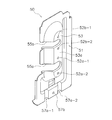
- FIG. 3 is an external view of a closing valve mounting plate 50.
- the perspective view which shows the state in which the closing valve 20 of the 1st structure was attached to the side bulging part 53.
- FIG. The front view of the closing valve 20 of the 1st structure and the side bulging part 53 at the time of seeing from the arrow direction of FIG.
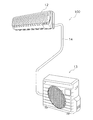
- FIG. 1 is an external view of an air conditioner 100 according to an embodiment of the present invention.
- the air conditioner 100 of FIG. 1 is configured by being divided into an indoor unit 12 attached to an indoor wall surface and the like and an outdoor unit 13 installed outside the room, and performs indoor cooling operation, heating operation, and the like. It can be carried out.
- An indoor heat exchanger (not shown) or the like is accommodated in the indoor unit 12, and an outdoor heat exchanger (not shown), a compressor (not shown), or the like is accommodated in the outdoor unit 13. ing.
- the indoor heat exchanger of the indoor unit 12 and the outdoor heat exchanger of the outdoor unit 13 are connected via a communication pipe 14.
- the communication pipe 14 includes a gas refrigerant communication pipe 14a attached to the gas refrigerant close valve 20a and a liquid refrigerant communication pipe 14b attached to the liquid refrigerant close valve 20b (see FIG. 2).
- FIG. 2 is a perspective view of the outdoor unit 13 from which the case side wall 412 and the closing valve cover 16 are removed.
- the outdoor unit 13 includes an outdoor heat exchanger (not shown), a compressor (not shown), an outdoor fan (not shown), an electrical component unit 45, and the like, and a casing 41 so as to surround them. And a closing valve cover 16.
- the outdoor unit 13 is provided with a closing valve mounting plate 50 for mounting the closing valve 20.
- the casing 41, the closing valve cover 16, and the closing valve mounting plate 50 will be described below.
- expressions indicating directions such as “up”, “down”, “left”, “right”, “vertical”, etc. are used as appropriate. As shown, each direction is shown in a state where it is attached outdoors and is normally used.
- the casing 41 has a substantially rectangular parallelepiped shape, and is formed of sheet metal and resin. As shown in FIG. 2, the casing 41 includes a case main body 411 and a case side wall portion 412. The inside of the casing 41 is divided into a machine room and a blower room by a partition plate. A compressor and an electrical component unit 45 are installed in the machine room, and an outdoor heat exchanger and an outdoor fan are installed in the air blowing chamber.
- the case main body 411 is a member that covers a compressor and an outdoor heat exchanger installed inside the casing 41, and as shown in FIG. 2, an air blowing port 411a and an air intake port (not shown) are formed.
- the air sucked into the case main body 411 from the outside of the outdoor unit 13 through the intake port is sent to the blower port 411a.
- Both the air blowing port 411a and the air intake port are provided in the air blowing chamber side portion of the casing 41.
- the case side wall portion 412 is disposed on the machine room side of the case main body 411, has a substantially flat shape, and is disposed along the vertical direction with respect to the bottom portion of the casing 41.
- various wirings connected to the electrical component unit 45 and openings 413 and 414 for exposing the communication pipe 14 connected to the outdoor heat exchanger via the closing valve 20 are formed. .
- the opening 413 is provided in the vicinity of the electrical component unit 45 in the case side wall 412, and the opening 414 is the closing valve 20 (gas refrigerant closing valve 20 a, liquid refrigerant closing in the case side wall 412. It is provided in the vicinity of the valve 20b).
- the closing valve 20 will be described later.
- the closing valve cover 16 is a cover attached so as to cover the openings 413 and 414. Since the closing valve 20 protrudes from the opening 414 of the casing 41, a portion corresponding to the opening 414 is formed to protrude.
- (2-3) Closing valve mounting plate 50 The closing valve mounting plate 50 will be described with reference to FIGS.
- FIG. 3 is an external view of the closing valve mounting plate 50.
- the closing valve mounting plate 50 has a side surface portion 51 and a side surface bulging portion 53.
- the side surface portion 51 is formed in a flat plate shape substantially along the vertical surface of the case side wall portion 412 of the casing 41 in a state where the closing valve mounting plate 50 is mounted on the casing 41. Further, the side surface 51 is formed in a vertically long shape along the vertical surface of the case side wall 412.
- the side surface bulging portion 53 is formed so as to protrude outward from the side surface portion 51 at a substantially central portion of the side surface portion 51.
- the side bulging portion 53 has a fixed surface 53a to which the closing valve 20 is attached at the top. Further, the side bulging portion 53 is formed in a trapezoidal shape with the width of the cross section narrowing toward the fixed surface 53a with the side surface portion 51 as the bottom.
- the fixed surface 53 a is formed in a flat plate shape substantially along the vertical surface of the case side wall portion 412 in a state where the closing valve mounting plate 50 is mounted on the casing 41.
- the fixed surface 53a has mounting holes 52a-1 and 52a-2 for mounting the gas refrigerant closing valve 20a to the fixed surface 53a, and an mounting hole for mounting the liquid refrigerant closing valve 20b to the fixed surface 53a.
- 52b-1 and 52b-2 are provided.
- notches 55 a and 55 b are formed from one of the vertically long sides of the side surface portion 51 to the fixed surface 53 a of the side surface bulging portion 53.
- the notches 55a and 55b are introduction portions for introducing the gas refrigerant closing valve 20a and the liquid refrigerant closing valve 20b into the fixed surface 53a, respectively.
- Recesses 57a-1 and 57a-2 and a screw hole 57b are formed in the lower portion of the side surface portion 51.
- the shut-off valve mounting plate 50 is attached so that the recesses 57a-1 and 57a-2 fit into the bottom of the casing 41, and is fixed to the bottom of the casing 41 with a screw that passes through the screw hole 57b.
- the shape of the closing valve 20 of the present embodiment is applicable to both the gas refrigerant closing valve 20a and the liquid refrigerant closing valve 20b, but the gas refrigerant closing valve 20a will be described below as an example. .
- the gas refrigerant closing valve 20a will be referred to as the closing valve 20 unless otherwise specified.
- the closing valve 20 is attached to the side bulging portion 53 of the closing valve mounting plate 50 as shown in FIGS.
- the shut-off valve 20 includes a cylindrical main body having a first cylindrical part 21 and a second cylindrical part 22, and a fourth cylindrical part 24 provided so as to branch from the cylindrical main body. And a cylindrical connection portion.
- a fixing portion 25 having a protruding fixing portion 25a and a protruding fixing portion 25b is provided at the bottom of the cylindrical main body, and the closing valve 20 is connected to the side bulging portion 53 via the protruding fixing portion 25a and the protruding fixing portion 25b. It is attached.
- FIG. 1 As shown in FIG.
- the fixed surface 53 a of the side bulging portion 53 is generally along the vertical surface of the case side wall portion 412. Therefore, when the closing valve 20 is attached to the closing valve mounting plate 50, the cylindrical connecting portion such as the fourth cylindrical portion 24 extends adjacent to the side bulging portion 53.
- Other connecting members can be connected to the cylindrical connecting portion, but it is necessary to work along the fixed surface 53a of the side bulging portion 53 when connecting the cylindrical connecting portion and the other connecting member. There is a bad workability. Therefore, in the present embodiment, a configuration that can improve workability when connecting a connecting member to the closing valve 20 is provided. As the configuration, a first configuration (FIGS.
- FIG. 4 is a perspective view showing a state in which the closing valve 20 having the first configuration is attached to the side bulging portion 53.
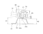
- FIG. 5 is a front view of the shut-off valve 20 and the side bulging portion 53 of the first configuration when viewed from the direction of the arrow in FIG. 4.
- FIG. 6 is a cross-sectional view of the first configuration closing valve 20 cut along the I-cut plane of FIG. 4.
- the closing valve 20 having the first configuration includes a first cylindrical portion 21, a second cylindrical portion 22, a third cylindrical portion 23, and a fourth cylindrical portion 24.
- a valve lid 70 is attached to the tip of the first cylindrical portion 21, a valve core cap 85 is attached to the tip of the third cylindrical portion 23, and a nut 88 such as a flare nut is attached to the tip of the fourth cylindrical portion 24.
- a connecting member such as the communication pipe 14 is connected to the tip of the fourth cylindrical portion 24, the nut 88 is removed.
- Each of the first to fourth cylindrical portions 21 to 24 has a substantially cylindrical shape with a through hole provided therein, and one end thereof is connected so that the inner peripheral surfaces of the through holes are continuous with each other.
- the first cylindrical portion 21 and the second cylindrical portion 22 have their central axes C1 positioned substantially on the same axis, and the first cylindrical portion 21 and the second cylindrical portion 22 constitute a cylindrical main body.
- the third cylindrical portion 23 and the fourth cylindrical portion 24 have their central axes C2 located substantially on the same axis, and the central axis C1 and the central axis C2 are substantially orthogonal.
- a fixed portion 25 that is continuous with the second cylindrical portion 22 is provided at the bottom of the second cylindrical portion 22.
- the fixing portion 25 includes a protruding fixing portion 25 a and a protruding fixing portion 25 b that protrude with respect to the second cylindrical portion 22.
- the protrusion fixing part 25 a and the protrusion fixing part 25 b are provided at positions that are symmetrical with respect to the outer surface of the second cylindrical part 22.
- the protruding fixing portion 25a is provided with a fastening hole 25a-1, and the protruding fixing portion 25b is similarly provided with a fastening hole 25b-1.
- Screws are inserted into the fastening holes 25a-1 and 25b-1 of the projecting fixing portions 25a and 25b and the mounting holes 52a-1 and 52a-2 (see FIG. 3) of the closing valve mounting plate 50 and screwed.
- the closing valve 20 is attached to the closing valve mounting plate 50. Therefore, the fixing surfaces 25c of the protruding fixing portions 25a and 25b of the closing valve 20 and the fixed surface 53a of the side bulge portion 53 are fixed so as to face each other.
- the protrusion fixing portions 25 a and 25 b are attached obliquely with respect to the second cylindrical portion 22.
- fixed part 25a, 25b is constant.
- the central axis C1 is inclined. More specifically, the central axes C1 of the first cylindrical portion 21 and the second cylindrical portion 22 are inclined with respect to a virtual central axis C53a orthogonal to the fixed surface 53a.
- the fixing surfaces 25c of the protruding fixing portions 25a and 25b and the fixed surface 53a of the side bulging portion 53 are on the same plane. Therefore, the protrusion fixing portions 25a and 25b are arranged so that the central axis C53a intersecting the fixing surface 25c of the protrusion fixing portions 25a and 25b is inclined with respect to the center axis C1 of the first cylindrical portion 21 and the second cylindrical portion 22. 2 It can be said that it is attached to the outer surface of the cylindrical portion 22.
- the fourth cylindrical portion 24 to which the connecting pipe 14 is connected extends with an angle of approximately 90 ° with respect to the first cylindrical portion 21 and the second cylindrical portion 22. Therefore, the center axis C2 is inclined with respect to the fixed surface 53a so that the tip of the fourth cylindrical portion 24 is separated from the fixed surface 53a of the side bulge portion 53.
- the fixed surface 53 a of the side surface bulging portion 53 is substantially along the plane of the side surface portion 51, and by extension, is generally along the vertical surface of the case side wall portion 412. Therefore, the central axis C ⁇ b> 2 of the fourth cylindrical portion 24 is inclined with respect to the vertical surface of the case side wall portion 412.
- the tip of the fourth cylindrical portion 24 is inclined so as to be separated from the vertical surface of the case side wall portion 412, and a space can be secured between the fourth cylindrical portion 24 and the vertical surface of the case side wall portion 412. Therefore, when connecting the communication pipe 14 to the fourth cylindrical portion 24, it is possible to work away from the vertical surface of the case side wall portion 412, and the vertical surface of the case side wall portion 412 is unlikely to obstruct connection. As a result, workability at the time of connection can be improved.
- the closing valve 20 having the first configuration includes a main body 80, a valve body 82, a valve lid 70, a valve core 84, a valve core cap 85, and a nut (not shown).
- the main body 80 includes a first cylindrical part 21, a second cylindrical part 22, a third cylindrical part 23, and a fourth cylindrical part 24.
- Each of the cylindrical portions 21 to 24 has a substantially cylindrical shape with a through hole provided therein, and one end thereof is connected so that the inner peripheral surfaces of the through holes are continuous with each other.
- An operation port 115 into which a wrench for moving the valve body 82 is inserted is provided at the other end of the first cylindrical portion 21.
- a second connection port 112 to which an internal pipe in the outdoor unit is connected is provided at the other end of the second cylindrical portion 22.
- a service port 114 to which a hose from a vacuum pump (not shown) is connected is provided at the other end of the third cylindrical portion 23 at the other end of the third cylindrical portion 23.
- the other end of the fourth cylindrical portion 24 is provided with a fourth connection port 111 to which the communication pipe 14 and the like are connected.
- a fixing portion 25 for fixing the closing valve 20 to the side bulging portion 53 is continuously formed at the other end of the second cylindrical portion 22.
- the fixing portion 25 has protruding fixing portions 25a and 25b, and the protruding fixing portions 25a and 25b are attached obliquely to the outer surface of the second cylindrical portion 22 as shown in FIG. Therefore, when the protruding fixing portions 25a and 25b are attached to the fixed surface 53a of the side bulging portion 53, the central axis C2 is set so that the tip of the fourth cylindrical portion 24 is separated from the fixing surface 53a of the side bulging portion 53. It is inclined with respect to the fixed surface 53a, and a space can be secured between the fourth cylindrical portion 24 and the vertical surface of the case side wall portion 412.
- the diameter D1 of the fourth cylindrical portion 24 is larger than the diameter D2 of the third cylindrical portion 23 (D1> D2). Therefore, when other connection members such as the communication pipe 14 are connected to the fourth cylindrical portion 24, the fixed surface 53 a of the side bulge portion 53 and the vertical surface of the case side wall portion 412 are likely to get in the way.
- the fourth cylindrical portion 24 is further away from the fixed surface 53a and the vertical surface of the case side wall portion 412 as it goes to the front end, so that the front end of the fourth cylindrical portion 24 and the vertical surface of the case side wall portion 412 A space is secured between them, and the vertical surface of the case side wall 412 is unlikely to obstruct connection.
- the diameter of the third cylindrical portion 23 is relatively small, the vertical surfaces of the fixed surface 53a and the case side wall portion 412 are not easily obstructed when another connecting member is connected to the third cylindrical portion 23.
- the central axes C2 of the fourth cylindrical portion 24 and the third cylindrical portion 23 are on the same axis, and the tip of the fourth cylindrical portion 24 is the side bulged portion 53. It inclines so that it may leave
- the first cylindrical portion 21 and the second cylindrical portion 22 constituting the cylindrical main body have their central axes C1 on the same axis and are arranged in a straight line.
- the third cylindrical portion 23 and the fourth cylindrical portion 24 form an angle of approximately 90 ° with respect to the central axis C ⁇ b> 2 of the first cylindrical portion 21 and the second cylindrical portion 22.
- a first refrigerant channel 95 a is provided inside the fourth cylindrical part 24, and a second refrigerant channel 95 b is provided inside the second cylindrical part 22.
- a valve core passage 93 is provided inside the third cylindrical portion 23, and a valve passage 94 is provided inside the first cylindrical portion 21.
- the first refrigerant flow path 95a, the second refrigerant flow path 95b, the valve core passage 93, and the valve passage 94 are arranged radially in four directions around the intermediate flow path 95c, and communicate with the intermediate flow path 95c. .
- the first refrigerant flow path 95a and the valve core passage 93 are arranged coaxially with the intermediate flow path 95c interposed therebetween, and the second refrigerant flow path 95b and the valve passage 94 are arranged coaxially with the intermediate flow path 95c interposed therebetween.
- the refrigerant flow path 95 has an L-shape bent at 90 degrees in the middle.
- the valve core passage 93 is disposed with an angle of approximately 90 ° with respect to the second refrigerant passage 95b.
- the first refrigerant passage 95a, the intermediate passage 95c, and the second refrigerant passage 95b are refrigerant passages through which refrigerant flows. 95 is formed.
- the direction from the valve passage 94 toward the second refrigerant passage 95b in the direction parallel to the axis passing through the second refrigerant passage 95b and the valve passage 94 is referred to as a first direction (see arrow A1 in FIG. 6).
- the direction from the second refrigerant channel 95b toward the valve passage 94 is referred to as a second direction (the direction opposite to the arrow A1 in FIG. 6).
- a valve seat 81 is provided in which the tip of the valve body 82 abuts and separates.
- the valve seat 81 increases in diameter in the second direction. It has a tapered shape.
- the valve body 82 has a substantially columnar shape, and is disposed in the valve passage 94 of the first cylindrical portion 21 so as to be movable in the axial direction.
- the tip of the valve body 82 faces the intermediate flow path 95c and has a tapered shape that decreases in diameter in the first direction.
- a hexagonal hole (not shown) into which a hexagonal wrench is inserted is formed at the rear end of the valve body 82, and the valve body 82 is axially rotated by rotating the valve body 82 together with the hexagonal wrench. Can be moved.
- the tip of the valve body 82 slightly protrudes from the valve passage 94 to the intermediate flow path 95c.
- the end of the valve body 82 and the second refrigerant flow path 95b are opened, and the intermediate flow path 95c is opened.
- the tip of the valve body 82 is in contact with the valve seat 81. In this state, the tip of the valve body 82 and the second refrigerant flow path 95b are closed without a gap, and the intermediate flow path 95c is closed.
- valve body 82 When closing the shut-off valve 20, the valve body 82 is moved in the first direction to bring the tip of the valve body 82 into contact with the valve seat 81, so that the first refrigerant channel 95a and the second refrigerant channel Block between 95b. Further, when opening the closing valve 20, the valve body 82 is moved in the second direction, so that the tip of the valve body 82 is separated from the valve seat 81, and the first refrigerant channel 95a and the second refrigerant channel 95b are connected. Communicate.
- An annular groove 82a is formed on the outer periphery of the valve body 82, and an O-ring 83 is fitted on the groove 82a. Thereby, the space between the inner peripheral surface of the valve passage 94 and the outer peripheral surface of the valve element 82 is sealed, so that the refrigerant does not leak to the outside.
- the valve lid 70 is normally attached to the other end of the first cylindrical portion 21 and closes the operation port 115.
- the valve lid 70 and the main body 80 are sealed with a seal member.
- the valve core 84 is inserted into the valve core passage 93 and closes the valve core passage 93.
- the valve core 84 is opened, and the communication pipe 14 connected to the fourth connection port 111 through the service port 114 and the fourth connection port 111 is evacuated.
- the valve core cap 85 is normally attached to the other end of the third cylindrical portion 23 and closes the service port 114.
- the valve core cap 85 is removed from the other end of the third cylindrical portion 23 when evacuating the communication pipe 14.
- the space between the inner peripheral screw 118 of the valve core cap 85 and the inner peripheral screw 117 of the third cylindrical portion 23 is sealed.
- FIG. 7 is a front view of the closing valve 20 and the side bulging portion 53 of the second configuration.
- FIG. 8 is a cross-sectional view of the second configuration of the shut-off valve 20 cut along the II cut surface of FIG.
- the first to fourth cylindrical portions 21 to 24 each have a substantially cylindrical shape in which through holes are provided, and the inner peripheral surfaces of the through holes are continuous with each other. One end is connected to.
- the first cylindrical portion 21 and the second cylindrical portion 22 have their central axes C1 positioned substantially on the same axis, and the first cylindrical portion 21 and the second cylindrical portion 22 constitute a cylindrical main body.
- the third cylindrical portion 23 and the fourth cylindrical portion 24 have their central axes C2 positioned substantially on the same axis, and are substantially orthogonal to the central axes C1 of the first cylindrical portion 21 and the second cylindrical portion 22.
- a valve lid 70 is attached to the tip of the first cylindrical portion 21, a valve core cap 85 is attached to the tip of the third cylindrical portion 23, and a nut 88 such as a flare nut is attached to the tip of the fourth cylindrical portion 24. .
- a connecting member such as the communication pipe 14 is connected to the tip of the fourth cylindrical portion 24, the nut 88 is removed.
- a fixed portion 25 that is continuous with the second cylindrical portion 22 is provided at the bottom of the second cylindrical portion 22.
- the fixing part 25 has a protruding fixing part 25a and a protruding fixing part 25b, like the closing valve 20 of the first configuration.
- the protruding fixing portions 25 a and 25 b are attached so as to be substantially orthogonal to the second cylindrical portion 22.
- fixed part 25a, 25b is constant. That is, the fixing surfaces 25c of the protruding fixing portions 25a and 25b and the central axes C1 of the first cylindrical portion 21 and the second cylindrical portion 22 are substantially orthogonal to each other.
- the fixed surface 53a of the side bulging portion 53 of the second configuration has an inclination with respect to the vertical surface of the side surface portion 51, and therefore has an inclination with respect to the vertical surface of the case side wall portion 412. Yes. That is, one height H1 of the side bulge portion 53 is larger than the other height H2 with respect to the vertical surface of the side surface portion 51 in FIG. 7 (H1> H2).
- the fourth cylindrical portion 24 is disposed on the height H1 side, and the third cylindrical portion 23 is disposed on the height H2 side, so that the protrusion fixing portion 25a and the protrusion fixing portion of the closing valve 20 are provided.
- 25 b is attached to the fixed surface 53 a of the side bulging portion 53.
- the central axis C ⁇ b> 2 of the fourth cylindrical portion 24 is inclined with respect to the vertical surface of the side surface portion 51, and is inclined away from the vertical surface of the side surface portion 51 toward the tip of the fourth cylindrical portion 24. Therefore, a space can be secured between the fourth cylindrical portion 24 and the vertical surface of the side surface portion 51, that is, between the fourth cylindrical portion 24 and the vertical surface of the case side wall portion 412. Therefore, when connecting the communication pipe 14 to the fourth cylindrical portion 24, it is possible to work away from the vertical surface of the case side wall portion 412, and the vertical surface of the case side wall portion 412 is unlikely to obstruct connection. As a result, workability at the time of connection can be improved.
- the closing valve 20 of the second configuration is different only in the configuration of the fixing portion 25 as compared to the closing valve 20 of the first configuration. That is, the fixing surfaces 25c of the protruding fixing portions 25a and 25b are formed in a direction along the third cylindrical portion 23 and the fourth cylindrical portion 24, that is, in a direction along the central axis C2 (see FIG. 7). Since other configurations are the same as those of the shut-off valve 20 of the first configuration, description thereof is omitted. The other configuration is the same as that of the first configuration of the shut-off valve 20, and the description thereof is omitted.
- the outdoor unit 13 connected to the indoor unit 12 includes a side bulging portion 53 and a closing valve 20.
- the side bulge portion 53 is formed on the case side wall portion 412 along the vertical plane, and bulges outward from the case side wall portion 412.
- the shut-off valve 20 has a fourth cylindrical portion 24 and a fixed portion 25 to which a communication pipe 14 extending from the indoor unit 12 is connected, and the central axis C2 of the fourth cylindrical portion 24 is inclined with respect to the vertical plane.
- the fourth cylindrical portion 24 is fixed to the side bulging portion 53 via the fixing portion 25 so as to move away from the vertical surface as it goes to the tip.
- the central axis of the fourth cylindrical portion 24 to which the connecting pipe 14 is connected is on the vertical surface of the case side wall portion 412 of the outdoor unit 13.
- it has an inclination. That is, the tip of the fourth cylindrical portion 24 is inclined so as to be separated from the vertical surface of the case side wall portion 412, and a space can be secured between the fourth cylindrical portion 24 and the vertical surface of the case side wall portion 412. Therefore, when connecting the communication pipe 14 to the fourth cylindrical portion 24, it is possible to work away from the vertical surface of the case side wall portion 412, and the vertical surface of the case side wall portion 412 is unlikely to obstruct connection.
- the fixed portion 25 of the shut-off valve 20 has a fixed surface 25 c that faces the side bulge portion 53.
- the central axis C2 of the fourth cylindrical portion 24 is inclined with respect to the fixed surface 25c. Therefore, when the fixed surface 25 c of the closing valve 20 is fixed to the side bulge portion 53 of the casing 41, the central axis of the fourth cylindrical portion 24 is inclined with respect to the vertical surface of the case side wall portion 412. A space can be secured between the fourth cylindrical portion 24 and the vertical surface of the case side wall portion 412 to improve workability during connection.
- the fixed portion 25 of the shut-off valve 20 has a fixed surface 25 c that faces the side bulge portion 53.
- the side bulging portion 53 has a fixed surface 53a facing the fixing surface 25c.
- the central axis of the fourth cylindrical portion 24 is parallel to the fixed surface 25c, and the fixed surface 53a is inclined with respect to the vertical surface.
- the central axis C2 of the fourth cylindrical portion 24 is parallel to the fixed surface 25c of the shut-off valve 20, but the fixed surface 53a of the side bulging portion 53 to which the fixed surface 25c is fixed is the case side wall portion. It is inclined with respect to the vertical surface 412.
- the protruding fixing portions 25 a and 25 b are obliquely attached to the second cylindrical portion 22, and hence the fourth connection port 111 side to which the connecting pipe 14 and the like are connected.
- the center axis C2 is inclined so that the tip of the fourth cylindrical portion 24 is away from the fixed surface 53a of the side bulge portion 53.
- the fourth cylindrical portion 24 is arranged on the height H1 side on the inclined fixed surface 53a as shown in FIG.
- the fixing portion 25 of the shut-off valve 20b is attached to the fixed surface 53a of the side bulge portion 53.
- the central axis C ⁇ b> 2 of the fourth cylindrical portion 24 is inclined with respect to the vertical surface of the side surface portion 51, that is, the vertical surface of the case side wall portion 412, and the vertical of the case side wall portion 412 increases toward the tip of the fourth cylindrical portion 24. Tilt away from the vertical surface.
- the same effect as that of the gas refrigerant closing valve 20a of the present embodiment can be obtained in the liquid refrigerant closing valve 20b.
- (5-2) Modification 1B in the above embodiment, in the state where the closing valve mounting plate 50 is mounted on the casing 41, the side surface portion 51 and the side surface bulging portion 53 are formed in a vertically long shape.
- the shape of the closing valve mounting plate 50 is not limited.
- the side surface portion 51 and the side surface bulging portion 53 may be formed horizontally long depending on the positions of the gas refrigerant closing valve 20a and the liquid refrigerant closing valve 20b. Good.
- the present invention is applicable to an air conditioner closing valve.
Landscapes
- Engineering & Computer Science (AREA)
- Chemical & Material Sciences (AREA)
- Combustion & Propulsion (AREA)
- Mechanical Engineering (AREA)
- General Engineering & Computer Science (AREA)
- Valve Housings (AREA)
- Other Air-Conditioning Systems (AREA)
Abstract
La présente invention vise à procurer une vanne qui est apte à améliorer l'aptitude au travail lors de la liaison d'un élément de liaison. A cet effet, selon l'invention, une unité extérieure (13), qui est reliée à une unité intérieure (12), comporte une partie saillante latérale (53) et une vanne d'arrêt (20). La partie saillante latérale (53) est formée sur une paroi latérale d'enceinte (412) qui s'étend le long d'un plan vertical, et fait saillie vers l'extérieur à partir de la paroi latérale d'enceinte (412). La vanne d'arrêt (20) a une quatrième section cylindrique (24) à laquelle un tuyau de communication (14), qui s'étend à partir de l'unité intérieure (12), est relié, et une section de fixation (25). Du fait que l'axe central (C2) de la quatrième section cylindrique (24) est incliné par rapport au plan vertical, la vanne est fixée à la partie saillante latérale (53) par l'intermédiaire de la section de fixation (25) de telle manière que l'axe central (C2) est plus loin à partir du plan vertical vers la pointe de la quatrième section cylindrique (24).
Priority Applications (2)
| Application Number | Priority Date | Filing Date | Title |
|---|---|---|---|
| CN201380067746.8A CN104884869B (zh) | 2012-12-26 | 2013-11-05 | 冷冻装置的热源单元 |
| EP13869493.0A EP2933573A4 (fr) | 2012-12-26 | 2013-11-05 | Unité de source de chaleur pour appareil de réfrigération |
Applications Claiming Priority (2)
| Application Number | Priority Date | Filing Date | Title |
|---|---|---|---|
| JP2012-283210 | 2012-12-26 | ||
| JP2012283210A JP5533999B1 (ja) | 2012-12-26 | 2012-12-26 | 冷凍装置の熱源ユニット |
Publications (1)
| Publication Number | Publication Date |
|---|---|
| WO2014103515A1 true WO2014103515A1 (fr) | 2014-07-03 |
Family
ID=51020614
Family Applications (1)
| Application Number | Title | Priority Date | Filing Date |
|---|---|---|---|
| PCT/JP2013/079882 WO2014103515A1 (fr) | 2012-12-26 | 2013-11-05 | Unité de source de chaleur pour appareil de réfrigération |
Country Status (4)
| Country | Link |
|---|---|
| EP (1) | EP2933573A4 (fr) |
| JP (1) | JP5533999B1 (fr) |
| CN (1) | CN104884869B (fr) |
| WO (1) | WO2014103515A1 (fr) |
Cited By (1)
| Publication number | Priority date | Publication date | Assignee | Title |
|---|---|---|---|---|
| EP3296661A4 (fr) * | 2015-05-11 | 2018-12-12 | Mitsubishi Electric Corporation | Appareil de pompe à chaleur |
Families Citing this family (2)
| Publication number | Priority date | Publication date | Assignee | Title |
|---|---|---|---|---|
| KR101900484B1 (ko) | 2015-01-23 | 2018-09-20 | 삼성전자주식회사 | 공기 조화기 |
| CN106447613A (zh) * | 2016-09-27 | 2017-02-22 | 西安蒜泥电子科技有限责任公司 | 一种基于图像局部配准的全景去虚影方法及系统 |
Citations (5)
| Publication number | Priority date | Publication date | Assignee | Title |
|---|---|---|---|---|
| JPS4994464U (fr) * | 1972-11-27 | 1974-08-15 | ||
| JPS61122466A (ja) * | 1984-11-19 | 1986-06-10 | 松下電器産業株式会社 | 空気調和機の弁固定装置 |
| JPH109717A (ja) | 1996-06-18 | 1998-01-16 | Taiheiyo Seiko Kk | ルームクーラー用サービスバルブ |
| JP2003254563A (ja) * | 2001-12-27 | 2003-09-10 | Sanyo Electric Co Ltd | 空気調和装置 |
| JP2007127312A (ja) * | 2005-11-02 | 2007-05-24 | Matsushita Electric Ind Co Ltd | 空気調和機の室外機 |
Family Cites Families (8)
| Publication number | Priority date | Publication date | Assignee | Title |
|---|---|---|---|---|
| JPS58168860A (ja) * | 1982-03-30 | 1983-10-05 | 松下電器産業株式会社 | 空気調和機の三方弁取付装置 |
| JPH04126931A (ja) * | 1990-09-18 | 1992-04-27 | Matsushita Seiko Co Ltd | 分離形空気調和機の室外機 |
| JP2000097453A (ja) * | 1998-09-22 | 2000-04-04 | Toshiba Corp | 空気調和機の室外機 |
| JP3223911B2 (ja) * | 1999-05-11 | 2001-10-29 | 株式会社日立製作所 | 空気調和機 |
| JP2003287243A (ja) * | 2002-03-28 | 2003-10-10 | Sanyo Electric Co Ltd | コンデンシングユニット |
| JP2005076955A (ja) * | 2003-08-29 | 2005-03-24 | Matsushita Electric Ind Co Ltd | 酸素富化機能付き空気調和機 |
| JP2011099636A (ja) * | 2009-11-06 | 2011-05-19 | Sharp Corp | 開閉弁 |
| JP5606355B2 (ja) * | 2011-02-15 | 2014-10-15 | 三菱電機株式会社 | 空気調和装置の室外ユニット |
-
2012
- 2012-12-26 JP JP2012283210A patent/JP5533999B1/ja active Active
-
2013
- 2013-11-05 WO PCT/JP2013/079882 patent/WO2014103515A1/fr active Application Filing
- 2013-11-05 CN CN201380067746.8A patent/CN104884869B/zh active Active
- 2013-11-05 EP EP13869493.0A patent/EP2933573A4/fr not_active Withdrawn
Patent Citations (5)
| Publication number | Priority date | Publication date | Assignee | Title |
|---|---|---|---|---|
| JPS4994464U (fr) * | 1972-11-27 | 1974-08-15 | ||
| JPS61122466A (ja) * | 1984-11-19 | 1986-06-10 | 松下電器産業株式会社 | 空気調和機の弁固定装置 |
| JPH109717A (ja) | 1996-06-18 | 1998-01-16 | Taiheiyo Seiko Kk | ルームクーラー用サービスバルブ |
| JP2003254563A (ja) * | 2001-12-27 | 2003-09-10 | Sanyo Electric Co Ltd | 空気調和装置 |
| JP2007127312A (ja) * | 2005-11-02 | 2007-05-24 | Matsushita Electric Ind Co Ltd | 空気調和機の室外機 |
Non-Patent Citations (1)
| Title |
|---|
| See also references of EP2933573A4 * |
Cited By (1)
| Publication number | Priority date | Publication date | Assignee | Title |
|---|---|---|---|---|
| EP3296661A4 (fr) * | 2015-05-11 | 2018-12-12 | Mitsubishi Electric Corporation | Appareil de pompe à chaleur |
Also Published As
| Publication number | Publication date |
|---|---|
| CN104884869A (zh) | 2015-09-02 |
| JP2014126275A (ja) | 2014-07-07 |
| CN104884869B (zh) | 2018-01-05 |
| EP2933573A4 (fr) | 2016-01-06 |
| EP2933573A1 (fr) | 2015-10-21 |
| JP5533999B1 (ja) | 2014-06-25 |
Similar Documents
| Publication | Publication Date | Title |
|---|---|---|
| JP4063296B2 (ja) | 閉鎖弁サポート部材及びそれを備えた空気調和装置の室外ユニット | |
| CN110425331B (zh) | 电动阀 | |
| KR101841373B1 (ko) | 증발기를 팽창 밸브에 결합하기 위한 장치 | |
| WO2006009047A1 (fr) | Climatiseur | |
| JP5533999B1 (ja) | 冷凍装置の熱源ユニット | |
| JP5527198B2 (ja) | 空気調和装置の室外機 | |
| JP5601367B2 (ja) | 弁 | |
| JP2016037983A (ja) | パイロット式電磁弁 | |
| JP6169034B2 (ja) | 空気調和機の室外機 | |
| EP3399188A1 (fr) | Compresseur emballé | |
| JP2005069177A (ja) | 遠心送風機のスクロールケーシング、それを備えた遠心送風機、その組立方法、及び空気調和装置の室内ユニット | |
| KR20230058143A (ko) | 스톱 밸브 및 이를 구비한 공조 시스템 | |
| KR20140103586A (ko) | 공기조화기용 서비스 밸브 어셈블리 | |
| JP6385566B2 (ja) | 空気調和機の室内機 | |
| JP2014047970A (ja) | 空気調和機の冷媒配管構造に関するものである。 | |
| JP2014126276A (ja) | 弁及び冷凍装置の熱源ユニット | |
| WO2012095011A1 (fr) | Système de réfrigération et soupape à expansion thermostatique de celui-ci | |
| JP2014126136A (ja) | 弁蓋及び弁 | |
| WO2021083264A1 (fr) | Ensemble boîtier de climatiseur et climatiseur | |
| EP3633284A1 (fr) | Orifice de raccordement de conduit et dispositif de ventilation | |
| WO2022068169A1 (fr) | Ensemble piston, ensemble compresseur et dispositif de réfrigération | |
| JP2011099636A (ja) | 開閉弁 | |
| KR200490398Y1 (ko) | 에어컨 컴프레셔용 튜브일체형 매니폴드 | |
| CN103307314B (zh) | 电磁四通换向阀 | |
| TW201702537A (zh) | 氣流交換裝置 |
Legal Events
| Date | Code | Title | Description |
|---|---|---|---|
| 121 | Ep: the epo has been informed by wipo that ep was designated in this application |
Ref document number: 13869493 Country of ref document: EP Kind code of ref document: A1 |
|
| NENP | Non-entry into the national phase |
Ref country code: DE |
|
| WWE | Wipo information: entry into national phase |
Ref document number: 2013869493 Country of ref document: EP |