WO2014103515A1 - Heat source unit for refrigeration apparatus - Google Patents
Heat source unit for refrigeration apparatus Download PDFInfo
- Publication number
- WO2014103515A1 WO2014103515A1 PCT/JP2013/079882 JP2013079882W WO2014103515A1 WO 2014103515 A1 WO2014103515 A1 WO 2014103515A1 JP 2013079882 W JP2013079882 W JP 2013079882W WO 2014103515 A1 WO2014103515 A1 WO 2014103515A1
- Authority
- WO
- WIPO (PCT)
- Prior art keywords
- valve
- cylindrical portion
- cylindrical
- closing valve
- fixing
- Prior art date
Links
Images


Classifications
-
- F—MECHANICAL ENGINEERING; LIGHTING; HEATING; WEAPONS; BLASTING
- F24—HEATING; RANGES; VENTILATING
- F24F—AIR-CONDITIONING; AIR-HUMIDIFICATION; VENTILATION; USE OF AIR CURRENTS FOR SCREENING
- F24F1/00—Room units for air-conditioning, e.g. separate or self-contained units or units receiving primary air from a central station
- F24F1/06—Separate outdoor units, e.g. outdoor unit to be linked to a separate room comprising a compressor and a heat exchanger
- F24F1/26—Refrigerant piping
- F24F1/32—Refrigerant piping for connecting the separate outdoor units to indoor units
-
- F—MECHANICAL ENGINEERING; LIGHTING; HEATING; WEAPONS; BLASTING
- F24—HEATING; RANGES; VENTILATING
- F24F—AIR-CONDITIONING; AIR-HUMIDIFICATION; VENTILATION; USE OF AIR CURRENTS FOR SCREENING
- F24F1/00—Room units for air-conditioning, e.g. separate or self-contained units or units receiving primary air from a central station
- F24F1/06—Separate outdoor units, e.g. outdoor unit to be linked to a separate room comprising a compressor and a heat exchanger
- F24F1/56—Casing or covers of separate outdoor units, e.g. fan guards
Definitions
- the present invention relates to a heat source unit of a refrigeration apparatus.
- Patent Document 1 Japanese Patent Laid-Open No. 10-9717 discloses a valve for opening and closing a path.
- the valve passage into which the valve element is inserted, the first passage, the second passage, and the third passage communicate with each other inside.
- Each passage is arranged such that the valve passage and the third passage are on the same axis, the first passage and the second passage are on the same axis, and the shafts cross each other in a cross shape.
- fixed part is provided in the front-end
- the fixed surface of the counterpart member is erected along the vertical direction, and when the valve of Patent Document 1 is fixed to the fixed surface of the counterpart member via the fixing portion, the first passage and the first passage The two passages are arranged along the fixed surface of the counterpart member. Therefore, when connecting other connecting members to the tips of the first passage and the second passage, it is necessary to work along the fixed surface of the mating member along the vertical direction, and workability is poor. Then, the objective of this invention aims at providing the valve which can improve workability
- the heat source unit of the refrigeration apparatus is a heat source unit of the refrigeration apparatus connected to the utilization unit, and includes a side bulge portion and a closing valve.
- the side bulge is formed on the side of the casing along the vertical plane, and bulges outward from the side.
- the shut-off valve has a cylindrical connection portion and a fixed portion to which a communication pipe extending from the usage unit is connected, and the central axis of the cylindrical connection portion is inclined with respect to a vertical plane, so that the end of the cylindrical connection portion is It is fixed to the side bulging part via the fixing part so as to be far away from the vertical surface.
- the heat source unit of the refrigeration apparatus according to the second aspect of the present invention is the heat source unit of the refrigeration apparatus according to the first aspect, wherein the fixing portion of the closing valve has a fixing surface facing the side bulging portion.
- the central axis of the cylindrical connecting portion is inclined with respect to the fixed surface.
- the fixing portion of the closing valve has a fixing surface facing the side bulging portion.
- the side bulge portion has a fixed surface that faces the fixed surface.
- the central axis of the cylindrical connecting portion is parallel to the fixed surface, and the fixed surface is inclined with respect to the vertical surface.
- workability at the time of connection can be improved.
- a space can be secured between the cylindrical connection portion and the vertical surface of the casing, and the connection between the cylindrical connection portion and the communication pipe is achieved. Workability at the time can be improved.
- FIG. 3 is an external view of a closing valve mounting plate 50.
- the perspective view which shows the state in which the closing valve 20 of the 1st structure was attached to the side bulging part 53.
- FIG. The front view of the closing valve 20 of the 1st structure and the side bulging part 53 at the time of seeing from the arrow direction of FIG.
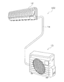
- FIG. 1 is an external view of an air conditioner 100 according to an embodiment of the present invention.
- the air conditioner 100 of FIG. 1 is configured by being divided into an indoor unit 12 attached to an indoor wall surface and the like and an outdoor unit 13 installed outside the room, and performs indoor cooling operation, heating operation, and the like. It can be carried out.
- An indoor heat exchanger (not shown) or the like is accommodated in the indoor unit 12, and an outdoor heat exchanger (not shown), a compressor (not shown), or the like is accommodated in the outdoor unit 13. ing.
- the indoor heat exchanger of the indoor unit 12 and the outdoor heat exchanger of the outdoor unit 13 are connected via a communication pipe 14.
- the communication pipe 14 includes a gas refrigerant communication pipe 14a attached to the gas refrigerant close valve 20a and a liquid refrigerant communication pipe 14b attached to the liquid refrigerant close valve 20b (see FIG. 2).
- FIG. 2 is a perspective view of the outdoor unit 13 from which the case side wall 412 and the closing valve cover 16 are removed.
- the outdoor unit 13 includes an outdoor heat exchanger (not shown), a compressor (not shown), an outdoor fan (not shown), an electrical component unit 45, and the like, and a casing 41 so as to surround them. And a closing valve cover 16.
- the outdoor unit 13 is provided with a closing valve mounting plate 50 for mounting the closing valve 20.
- the casing 41, the closing valve cover 16, and the closing valve mounting plate 50 will be described below.
- expressions indicating directions such as “up”, “down”, “left”, “right”, “vertical”, etc. are used as appropriate. As shown, each direction is shown in a state where it is attached outdoors and is normally used.
- the casing 41 has a substantially rectangular parallelepiped shape, and is formed of sheet metal and resin. As shown in FIG. 2, the casing 41 includes a case main body 411 and a case side wall portion 412. The inside of the casing 41 is divided into a machine room and a blower room by a partition plate. A compressor and an electrical component unit 45 are installed in the machine room, and an outdoor heat exchanger and an outdoor fan are installed in the air blowing chamber.
- the case main body 411 is a member that covers a compressor and an outdoor heat exchanger installed inside the casing 41, and as shown in FIG. 2, an air blowing port 411a and an air intake port (not shown) are formed.
- the air sucked into the case main body 411 from the outside of the outdoor unit 13 through the intake port is sent to the blower port 411a.
- Both the air blowing port 411a and the air intake port are provided in the air blowing chamber side portion of the casing 41.
- the case side wall portion 412 is disposed on the machine room side of the case main body 411, has a substantially flat shape, and is disposed along the vertical direction with respect to the bottom portion of the casing 41.
- various wirings connected to the electrical component unit 45 and openings 413 and 414 for exposing the communication pipe 14 connected to the outdoor heat exchanger via the closing valve 20 are formed. .
- the opening 413 is provided in the vicinity of the electrical component unit 45 in the case side wall 412, and the opening 414 is the closing valve 20 (gas refrigerant closing valve 20 a, liquid refrigerant closing in the case side wall 412. It is provided in the vicinity of the valve 20b).
- the closing valve 20 will be described later.
- the closing valve cover 16 is a cover attached so as to cover the openings 413 and 414. Since the closing valve 20 protrudes from the opening 414 of the casing 41, a portion corresponding to the opening 414 is formed to protrude.
- (2-3) Closing valve mounting plate 50 The closing valve mounting plate 50 will be described with reference to FIGS.
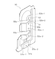
- FIG. 3 is an external view of the closing valve mounting plate 50.
- the closing valve mounting plate 50 has a side surface portion 51 and a side surface bulging portion 53.
- the side surface portion 51 is formed in a flat plate shape substantially along the vertical surface of the case side wall portion 412 of the casing 41 in a state where the closing valve mounting plate 50 is mounted on the casing 41. Further, the side surface 51 is formed in a vertically long shape along the vertical surface of the case side wall 412.
- the side surface bulging portion 53 is formed so as to protrude outward from the side surface portion 51 at a substantially central portion of the side surface portion 51.
- the side bulging portion 53 has a fixed surface 53a to which the closing valve 20 is attached at the top. Further, the side bulging portion 53 is formed in a trapezoidal shape with the width of the cross section narrowing toward the fixed surface 53a with the side surface portion 51 as the bottom.
- the fixed surface 53 a is formed in a flat plate shape substantially along the vertical surface of the case side wall portion 412 in a state where the closing valve mounting plate 50 is mounted on the casing 41.
- the fixed surface 53a has mounting holes 52a-1 and 52a-2 for mounting the gas refrigerant closing valve 20a to the fixed surface 53a, and an mounting hole for mounting the liquid refrigerant closing valve 20b to the fixed surface 53a.
- 52b-1 and 52b-2 are provided.
- notches 55 a and 55 b are formed from one of the vertically long sides of the side surface portion 51 to the fixed surface 53 a of the side surface bulging portion 53.
- the notches 55a and 55b are introduction portions for introducing the gas refrigerant closing valve 20a and the liquid refrigerant closing valve 20b into the fixed surface 53a, respectively.
- Recesses 57a-1 and 57a-2 and a screw hole 57b are formed in the lower portion of the side surface portion 51.
- the shut-off valve mounting plate 50 is attached so that the recesses 57a-1 and 57a-2 fit into the bottom of the casing 41, and is fixed to the bottom of the casing 41 with a screw that passes through the screw hole 57b.
- the shape of the closing valve 20 of the present embodiment is applicable to both the gas refrigerant closing valve 20a and the liquid refrigerant closing valve 20b, but the gas refrigerant closing valve 20a will be described below as an example. .
- the gas refrigerant closing valve 20a will be referred to as the closing valve 20 unless otherwise specified.
- the closing valve 20 is attached to the side bulging portion 53 of the closing valve mounting plate 50 as shown in FIGS.
- the shut-off valve 20 includes a cylindrical main body having a first cylindrical part 21 and a second cylindrical part 22, and a fourth cylindrical part 24 provided so as to branch from the cylindrical main body. And a cylindrical connection portion.
- a fixing portion 25 having a protruding fixing portion 25a and a protruding fixing portion 25b is provided at the bottom of the cylindrical main body, and the closing valve 20 is connected to the side bulging portion 53 via the protruding fixing portion 25a and the protruding fixing portion 25b. It is attached.
- FIG. 1 As shown in FIG.
- the fixed surface 53 a of the side bulging portion 53 is generally along the vertical surface of the case side wall portion 412. Therefore, when the closing valve 20 is attached to the closing valve mounting plate 50, the cylindrical connecting portion such as the fourth cylindrical portion 24 extends adjacent to the side bulging portion 53.
- Other connecting members can be connected to the cylindrical connecting portion, but it is necessary to work along the fixed surface 53a of the side bulging portion 53 when connecting the cylindrical connecting portion and the other connecting member. There is a bad workability. Therefore, in the present embodiment, a configuration that can improve workability when connecting a connecting member to the closing valve 20 is provided. As the configuration, a first configuration (FIGS.
- FIG. 4 is a perspective view showing a state in which the closing valve 20 having the first configuration is attached to the side bulging portion 53.
- FIG. 5 is a front view of the shut-off valve 20 and the side bulging portion 53 of the first configuration when viewed from the direction of the arrow in FIG. 4.
- FIG. 6 is a cross-sectional view of the first configuration closing valve 20 cut along the I-cut plane of FIG. 4.
- the closing valve 20 having the first configuration includes a first cylindrical portion 21, a second cylindrical portion 22, a third cylindrical portion 23, and a fourth cylindrical portion 24.
- a valve lid 70 is attached to the tip of the first cylindrical portion 21, a valve core cap 85 is attached to the tip of the third cylindrical portion 23, and a nut 88 such as a flare nut is attached to the tip of the fourth cylindrical portion 24.
- a connecting member such as the communication pipe 14 is connected to the tip of the fourth cylindrical portion 24, the nut 88 is removed.
- Each of the first to fourth cylindrical portions 21 to 24 has a substantially cylindrical shape with a through hole provided therein, and one end thereof is connected so that the inner peripheral surfaces of the through holes are continuous with each other.
- the first cylindrical portion 21 and the second cylindrical portion 22 have their central axes C1 positioned substantially on the same axis, and the first cylindrical portion 21 and the second cylindrical portion 22 constitute a cylindrical main body.
- the third cylindrical portion 23 and the fourth cylindrical portion 24 have their central axes C2 located substantially on the same axis, and the central axis C1 and the central axis C2 are substantially orthogonal.
- a fixed portion 25 that is continuous with the second cylindrical portion 22 is provided at the bottom of the second cylindrical portion 22.
- the fixing portion 25 includes a protruding fixing portion 25 a and a protruding fixing portion 25 b that protrude with respect to the second cylindrical portion 22.
- the protrusion fixing part 25 a and the protrusion fixing part 25 b are provided at positions that are symmetrical with respect to the outer surface of the second cylindrical part 22.
- the protruding fixing portion 25a is provided with a fastening hole 25a-1, and the protruding fixing portion 25b is similarly provided with a fastening hole 25b-1.
- Screws are inserted into the fastening holes 25a-1 and 25b-1 of the projecting fixing portions 25a and 25b and the mounting holes 52a-1 and 52a-2 (see FIG. 3) of the closing valve mounting plate 50 and screwed.
- the closing valve 20 is attached to the closing valve mounting plate 50. Therefore, the fixing surfaces 25c of the protruding fixing portions 25a and 25b of the closing valve 20 and the fixed surface 53a of the side bulge portion 53 are fixed so as to face each other.
- the protrusion fixing portions 25 a and 25 b are attached obliquely with respect to the second cylindrical portion 22.
- fixed part 25a, 25b is constant.
- the central axis C1 is inclined. More specifically, the central axes C1 of the first cylindrical portion 21 and the second cylindrical portion 22 are inclined with respect to a virtual central axis C53a orthogonal to the fixed surface 53a.
- the fixing surfaces 25c of the protruding fixing portions 25a and 25b and the fixed surface 53a of the side bulging portion 53 are on the same plane. Therefore, the protrusion fixing portions 25a and 25b are arranged so that the central axis C53a intersecting the fixing surface 25c of the protrusion fixing portions 25a and 25b is inclined with respect to the center axis C1 of the first cylindrical portion 21 and the second cylindrical portion 22. 2 It can be said that it is attached to the outer surface of the cylindrical portion 22.
- the fourth cylindrical portion 24 to which the connecting pipe 14 is connected extends with an angle of approximately 90 ° with respect to the first cylindrical portion 21 and the second cylindrical portion 22. Therefore, the center axis C2 is inclined with respect to the fixed surface 53a so that the tip of the fourth cylindrical portion 24 is separated from the fixed surface 53a of the side bulge portion 53.
- the fixed surface 53 a of the side surface bulging portion 53 is substantially along the plane of the side surface portion 51, and by extension, is generally along the vertical surface of the case side wall portion 412. Therefore, the central axis C ⁇ b> 2 of the fourth cylindrical portion 24 is inclined with respect to the vertical surface of the case side wall portion 412.
- the tip of the fourth cylindrical portion 24 is inclined so as to be separated from the vertical surface of the case side wall portion 412, and a space can be secured between the fourth cylindrical portion 24 and the vertical surface of the case side wall portion 412. Therefore, when connecting the communication pipe 14 to the fourth cylindrical portion 24, it is possible to work away from the vertical surface of the case side wall portion 412, and the vertical surface of the case side wall portion 412 is unlikely to obstruct connection. As a result, workability at the time of connection can be improved.
- the closing valve 20 having the first configuration includes a main body 80, a valve body 82, a valve lid 70, a valve core 84, a valve core cap 85, and a nut (not shown).
- the main body 80 includes a first cylindrical part 21, a second cylindrical part 22, a third cylindrical part 23, and a fourth cylindrical part 24.
- Each of the cylindrical portions 21 to 24 has a substantially cylindrical shape with a through hole provided therein, and one end thereof is connected so that the inner peripheral surfaces of the through holes are continuous with each other.
- An operation port 115 into which a wrench for moving the valve body 82 is inserted is provided at the other end of the first cylindrical portion 21.
- a second connection port 112 to which an internal pipe in the outdoor unit is connected is provided at the other end of the second cylindrical portion 22.
- a service port 114 to which a hose from a vacuum pump (not shown) is connected is provided at the other end of the third cylindrical portion 23 at the other end of the third cylindrical portion 23.
- the other end of the fourth cylindrical portion 24 is provided with a fourth connection port 111 to which the communication pipe 14 and the like are connected.
- a fixing portion 25 for fixing the closing valve 20 to the side bulging portion 53 is continuously formed at the other end of the second cylindrical portion 22.
- the fixing portion 25 has protruding fixing portions 25a and 25b, and the protruding fixing portions 25a and 25b are attached obliquely to the outer surface of the second cylindrical portion 22 as shown in FIG. Therefore, when the protruding fixing portions 25a and 25b are attached to the fixed surface 53a of the side bulging portion 53, the central axis C2 is set so that the tip of the fourth cylindrical portion 24 is separated from the fixing surface 53a of the side bulging portion 53. It is inclined with respect to the fixed surface 53a, and a space can be secured between the fourth cylindrical portion 24 and the vertical surface of the case side wall portion 412.
- the diameter D1 of the fourth cylindrical portion 24 is larger than the diameter D2 of the third cylindrical portion 23 (D1> D2). Therefore, when other connection members such as the communication pipe 14 are connected to the fourth cylindrical portion 24, the fixed surface 53 a of the side bulge portion 53 and the vertical surface of the case side wall portion 412 are likely to get in the way.
- the fourth cylindrical portion 24 is further away from the fixed surface 53a and the vertical surface of the case side wall portion 412 as it goes to the front end, so that the front end of the fourth cylindrical portion 24 and the vertical surface of the case side wall portion 412 A space is secured between them, and the vertical surface of the case side wall 412 is unlikely to obstruct connection.
- the diameter of the third cylindrical portion 23 is relatively small, the vertical surfaces of the fixed surface 53a and the case side wall portion 412 are not easily obstructed when another connecting member is connected to the third cylindrical portion 23.
- the central axes C2 of the fourth cylindrical portion 24 and the third cylindrical portion 23 are on the same axis, and the tip of the fourth cylindrical portion 24 is the side bulged portion 53. It inclines so that it may leave
- the first cylindrical portion 21 and the second cylindrical portion 22 constituting the cylindrical main body have their central axes C1 on the same axis and are arranged in a straight line.
- the third cylindrical portion 23 and the fourth cylindrical portion 24 form an angle of approximately 90 ° with respect to the central axis C ⁇ b> 2 of the first cylindrical portion 21 and the second cylindrical portion 22.
- a first refrigerant channel 95 a is provided inside the fourth cylindrical part 24, and a second refrigerant channel 95 b is provided inside the second cylindrical part 22.
- a valve core passage 93 is provided inside the third cylindrical portion 23, and a valve passage 94 is provided inside the first cylindrical portion 21.
- the first refrigerant flow path 95a, the second refrigerant flow path 95b, the valve core passage 93, and the valve passage 94 are arranged radially in four directions around the intermediate flow path 95c, and communicate with the intermediate flow path 95c. .
- the first refrigerant flow path 95a and the valve core passage 93 are arranged coaxially with the intermediate flow path 95c interposed therebetween, and the second refrigerant flow path 95b and the valve passage 94 are arranged coaxially with the intermediate flow path 95c interposed therebetween.
- the refrigerant flow path 95 has an L-shape bent at 90 degrees in the middle.
- the valve core passage 93 is disposed with an angle of approximately 90 ° with respect to the second refrigerant passage 95b.
- the first refrigerant passage 95a, the intermediate passage 95c, and the second refrigerant passage 95b are refrigerant passages through which refrigerant flows. 95 is formed.
- the direction from the valve passage 94 toward the second refrigerant passage 95b in the direction parallel to the axis passing through the second refrigerant passage 95b and the valve passage 94 is referred to as a first direction (see arrow A1 in FIG. 6).
- the direction from the second refrigerant channel 95b toward the valve passage 94 is referred to as a second direction (the direction opposite to the arrow A1 in FIG. 6).
- a valve seat 81 is provided in which the tip of the valve body 82 abuts and separates.
- the valve seat 81 increases in diameter in the second direction. It has a tapered shape.
- the valve body 82 has a substantially columnar shape, and is disposed in the valve passage 94 of the first cylindrical portion 21 so as to be movable in the axial direction.
- the tip of the valve body 82 faces the intermediate flow path 95c and has a tapered shape that decreases in diameter in the first direction.
- a hexagonal hole (not shown) into which a hexagonal wrench is inserted is formed at the rear end of the valve body 82, and the valve body 82 is axially rotated by rotating the valve body 82 together with the hexagonal wrench. Can be moved.
- the tip of the valve body 82 slightly protrudes from the valve passage 94 to the intermediate flow path 95c.
- the end of the valve body 82 and the second refrigerant flow path 95b are opened, and the intermediate flow path 95c is opened.
- the tip of the valve body 82 is in contact with the valve seat 81. In this state, the tip of the valve body 82 and the second refrigerant flow path 95b are closed without a gap, and the intermediate flow path 95c is closed.
- valve body 82 When closing the shut-off valve 20, the valve body 82 is moved in the first direction to bring the tip of the valve body 82 into contact with the valve seat 81, so that the first refrigerant channel 95a and the second refrigerant channel Block between 95b. Further, when opening the closing valve 20, the valve body 82 is moved in the second direction, so that the tip of the valve body 82 is separated from the valve seat 81, and the first refrigerant channel 95a and the second refrigerant channel 95b are connected. Communicate.
- An annular groove 82a is formed on the outer periphery of the valve body 82, and an O-ring 83 is fitted on the groove 82a. Thereby, the space between the inner peripheral surface of the valve passage 94 and the outer peripheral surface of the valve element 82 is sealed, so that the refrigerant does not leak to the outside.
- the valve lid 70 is normally attached to the other end of the first cylindrical portion 21 and closes the operation port 115.
- the valve lid 70 and the main body 80 are sealed with a seal member.
- the valve core 84 is inserted into the valve core passage 93 and closes the valve core passage 93.
- the valve core 84 is opened, and the communication pipe 14 connected to the fourth connection port 111 through the service port 114 and the fourth connection port 111 is evacuated.
- the valve core cap 85 is normally attached to the other end of the third cylindrical portion 23 and closes the service port 114.
- the valve core cap 85 is removed from the other end of the third cylindrical portion 23 when evacuating the communication pipe 14.
- the space between the inner peripheral screw 118 of the valve core cap 85 and the inner peripheral screw 117 of the third cylindrical portion 23 is sealed.
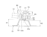
- FIG. 7 is a front view of the closing valve 20 and the side bulging portion 53 of the second configuration.
- FIG. 8 is a cross-sectional view of the second configuration of the shut-off valve 20 cut along the II cut surface of FIG.
- the first to fourth cylindrical portions 21 to 24 each have a substantially cylindrical shape in which through holes are provided, and the inner peripheral surfaces of the through holes are continuous with each other. One end is connected to.
- the first cylindrical portion 21 and the second cylindrical portion 22 have their central axes C1 positioned substantially on the same axis, and the first cylindrical portion 21 and the second cylindrical portion 22 constitute a cylindrical main body.
- the third cylindrical portion 23 and the fourth cylindrical portion 24 have their central axes C2 positioned substantially on the same axis, and are substantially orthogonal to the central axes C1 of the first cylindrical portion 21 and the second cylindrical portion 22.
- a valve lid 70 is attached to the tip of the first cylindrical portion 21, a valve core cap 85 is attached to the tip of the third cylindrical portion 23, and a nut 88 such as a flare nut is attached to the tip of the fourth cylindrical portion 24. .
- a connecting member such as the communication pipe 14 is connected to the tip of the fourth cylindrical portion 24, the nut 88 is removed.
- a fixed portion 25 that is continuous with the second cylindrical portion 22 is provided at the bottom of the second cylindrical portion 22.
- the fixing part 25 has a protruding fixing part 25a and a protruding fixing part 25b, like the closing valve 20 of the first configuration.
- the protruding fixing portions 25 a and 25 b are attached so as to be substantially orthogonal to the second cylindrical portion 22.
- fixed part 25a, 25b is constant. That is, the fixing surfaces 25c of the protruding fixing portions 25a and 25b and the central axes C1 of the first cylindrical portion 21 and the second cylindrical portion 22 are substantially orthogonal to each other.
- the fixed surface 53a of the side bulging portion 53 of the second configuration has an inclination with respect to the vertical surface of the side surface portion 51, and therefore has an inclination with respect to the vertical surface of the case side wall portion 412. Yes. That is, one height H1 of the side bulge portion 53 is larger than the other height H2 with respect to the vertical surface of the side surface portion 51 in FIG. 7 (H1> H2).
- the fourth cylindrical portion 24 is disposed on the height H1 side, and the third cylindrical portion 23 is disposed on the height H2 side, so that the protrusion fixing portion 25a and the protrusion fixing portion of the closing valve 20 are provided.
- 25 b is attached to the fixed surface 53 a of the side bulging portion 53.
- the central axis C ⁇ b> 2 of the fourth cylindrical portion 24 is inclined with respect to the vertical surface of the side surface portion 51, and is inclined away from the vertical surface of the side surface portion 51 toward the tip of the fourth cylindrical portion 24. Therefore, a space can be secured between the fourth cylindrical portion 24 and the vertical surface of the side surface portion 51, that is, between the fourth cylindrical portion 24 and the vertical surface of the case side wall portion 412. Therefore, when connecting the communication pipe 14 to the fourth cylindrical portion 24, it is possible to work away from the vertical surface of the case side wall portion 412, and the vertical surface of the case side wall portion 412 is unlikely to obstruct connection. As a result, workability at the time of connection can be improved.
- the closing valve 20 of the second configuration is different only in the configuration of the fixing portion 25 as compared to the closing valve 20 of the first configuration. That is, the fixing surfaces 25c of the protruding fixing portions 25a and 25b are formed in a direction along the third cylindrical portion 23 and the fourth cylindrical portion 24, that is, in a direction along the central axis C2 (see FIG. 7). Since other configurations are the same as those of the shut-off valve 20 of the first configuration, description thereof is omitted. The other configuration is the same as that of the first configuration of the shut-off valve 20, and the description thereof is omitted.
- the outdoor unit 13 connected to the indoor unit 12 includes a side bulging portion 53 and a closing valve 20.
- the side bulge portion 53 is formed on the case side wall portion 412 along the vertical plane, and bulges outward from the case side wall portion 412.
- the shut-off valve 20 has a fourth cylindrical portion 24 and a fixed portion 25 to which a communication pipe 14 extending from the indoor unit 12 is connected, and the central axis C2 of the fourth cylindrical portion 24 is inclined with respect to the vertical plane.
- the fourth cylindrical portion 24 is fixed to the side bulging portion 53 via the fixing portion 25 so as to move away from the vertical surface as it goes to the tip.
- the central axis of the fourth cylindrical portion 24 to which the connecting pipe 14 is connected is on the vertical surface of the case side wall portion 412 of the outdoor unit 13.
- it has an inclination. That is, the tip of the fourth cylindrical portion 24 is inclined so as to be separated from the vertical surface of the case side wall portion 412, and a space can be secured between the fourth cylindrical portion 24 and the vertical surface of the case side wall portion 412. Therefore, when connecting the communication pipe 14 to the fourth cylindrical portion 24, it is possible to work away from the vertical surface of the case side wall portion 412, and the vertical surface of the case side wall portion 412 is unlikely to obstruct connection.
- the fixed portion 25 of the shut-off valve 20 has a fixed surface 25 c that faces the side bulge portion 53.
- the central axis C2 of the fourth cylindrical portion 24 is inclined with respect to the fixed surface 25c. Therefore, when the fixed surface 25 c of the closing valve 20 is fixed to the side bulge portion 53 of the casing 41, the central axis of the fourth cylindrical portion 24 is inclined with respect to the vertical surface of the case side wall portion 412. A space can be secured between the fourth cylindrical portion 24 and the vertical surface of the case side wall portion 412 to improve workability during connection.
- the fixed portion 25 of the shut-off valve 20 has a fixed surface 25 c that faces the side bulge portion 53.
- the side bulging portion 53 has a fixed surface 53a facing the fixing surface 25c.
- the central axis of the fourth cylindrical portion 24 is parallel to the fixed surface 25c, and the fixed surface 53a is inclined with respect to the vertical surface.
- the central axis C2 of the fourth cylindrical portion 24 is parallel to the fixed surface 25c of the shut-off valve 20, but the fixed surface 53a of the side bulging portion 53 to which the fixed surface 25c is fixed is the case side wall portion. It is inclined with respect to the vertical surface 412.
- the protruding fixing portions 25 a and 25 b are obliquely attached to the second cylindrical portion 22, and hence the fourth connection port 111 side to which the connecting pipe 14 and the like are connected.
- the center axis C2 is inclined so that the tip of the fourth cylindrical portion 24 is away from the fixed surface 53a of the side bulge portion 53.
- the fourth cylindrical portion 24 is arranged on the height H1 side on the inclined fixed surface 53a as shown in FIG.
- the fixing portion 25 of the shut-off valve 20b is attached to the fixed surface 53a of the side bulge portion 53.
- the central axis C ⁇ b> 2 of the fourth cylindrical portion 24 is inclined with respect to the vertical surface of the side surface portion 51, that is, the vertical surface of the case side wall portion 412, and the vertical of the case side wall portion 412 increases toward the tip of the fourth cylindrical portion 24. Tilt away from the vertical surface.
- the same effect as that of the gas refrigerant closing valve 20a of the present embodiment can be obtained in the liquid refrigerant closing valve 20b.
- (5-2) Modification 1B in the above embodiment, in the state where the closing valve mounting plate 50 is mounted on the casing 41, the side surface portion 51 and the side surface bulging portion 53 are formed in a vertically long shape.
- the shape of the closing valve mounting plate 50 is not limited.
- the side surface portion 51 and the side surface bulging portion 53 may be formed horizontally long depending on the positions of the gas refrigerant closing valve 20a and the liquid refrigerant closing valve 20b. Good.
- the present invention is applicable to an air conditioner closing valve.
Abstract
The purpose of the present invention is to provide a valve that is capable of improving workability when connecting a connection member. An outdoor unit (13), which is connected to an indoor unit (12), is provided with a side protruding part (53) and a shutoff valve (20). The side protruding part (53) is formed on a case side wall (412) that runs along a vertical plane, and protrudes to the outside from the case side wall (412). The shutoff valve (20) has a fourth cylindrical section (24) to which a communication pipe (14), which extends from the indoor unit (12), is connected, and a fixing section (25). Due to the center axis (C2) of the fourth cylindrical section (24) being inclined relative to the vertical plane, the valve is fixed to the side protruding part (53) via the fixing section (25) in such a manner that the center axis (C2) is further from the vertical plane toward the tip of the fourth cylindrical section (24).
Description
本発明は、冷凍装置の熱源ユニットに関する。
The present invention relates to a heat source unit of a refrigeration apparatus.
特許文献1(特開平10-9717号公報)には、経路の開閉を行うための弁が開示されている。特許文献1の弁では、弁体が挿入される弁通路と、第1通路と、第2通路と、第3通路とが内部において連通している。各通路は、弁通路と第3通路とが同一軸上に、第1通路と第2通路とが同一軸上に、各軸が十字に交差するように配置されている。また、弁通路の同一軸上に続く第3通路の先端部には固定部が設けられており、弁は固定部を介して相手側部材の被固定面に固定され得る。
Patent Document 1 (Japanese Patent Laid-Open No. 10-9717) discloses a valve for opening and closing a path. In the valve of Patent Document 1, the valve passage into which the valve element is inserted, the first passage, the second passage, and the third passage communicate with each other inside. Each passage is arranged such that the valve passage and the third passage are on the same axis, the first passage and the second passage are on the same axis, and the shafts cross each other in a cross shape. Moreover, the fixing | fixed part is provided in the front-end | tip part of the 3rd channel | path continuing on the same axis | shaft of a valve channel | path, and a valve can be fixed to the to-be-fixed surface of the other party member via a fixing | fixed part.
通常、相手側部材の被固定面は鉛直方向に沿って立設されており、特許文献1の弁が固定部を介して相手側部材の被固定面に固定されると、第1通路及び第2通路は相手側部材の被固定面に沿うように配置される。そのため、第1通路及び第2通路の先端に他の接続部材を接続する際に、鉛直方向に沿った相手側部材の被固定面に沿うように作業を行う必要があり作業性が悪い。
そこで、本発明の目的は、接続部材を接続する際に作業性を向上可能な弁を提供することを目的とする。 Usually, the fixed surface of the counterpart member is erected along the vertical direction, and when the valve ofPatent Document 1 is fixed to the fixed surface of the counterpart member via the fixing portion, the first passage and the first passage The two passages are arranged along the fixed surface of the counterpart member. Therefore, when connecting other connecting members to the tips of the first passage and the second passage, it is necessary to work along the fixed surface of the mating member along the vertical direction, and workability is poor.
Then, the objective of this invention aims at providing the valve which can improve workability | operativity when connecting a connection member.
そこで、本発明の目的は、接続部材を接続する際に作業性を向上可能な弁を提供することを目的とする。 Usually, the fixed surface of the counterpart member is erected along the vertical direction, and when the valve of
Then, the objective of this invention aims at providing the valve which can improve workability | operativity when connecting a connection member.
本発明の第1観点に係る冷凍装置の熱源ユニットは、利用ユニットと接続された冷凍装置の熱源ユニットであって、側面膨出部と、閉鎖弁とを備える。側面膨出部は、鉛直面に沿うケーシングの側面部に形成されており、側面部から外側に膨出する。閉鎖弁は、利用ユニットから延びる連絡配管が接続される円筒状接続部及び固定部を有し、円筒状接続部の中心軸が鉛直面に対して傾斜することにより、円筒状接続部の先端にいくほど鉛直面から離れるように固定部を介して側面膨出部に固定される。
これにより、円筒状接続部に連絡配管を接続する際にケーシングの鉛直面から離れて作業が可能であり、ケーシングの鉛直面が接続の邪魔になりにくい。そのため、接続時の作業性を向上させることができる。 The heat source unit of the refrigeration apparatus according to the first aspect of the present invention is a heat source unit of the refrigeration apparatus connected to the utilization unit, and includes a side bulge portion and a closing valve. The side bulge is formed on the side of the casing along the vertical plane, and bulges outward from the side. The shut-off valve has a cylindrical connection portion and a fixed portion to which a communication pipe extending from the usage unit is connected, and the central axis of the cylindrical connection portion is inclined with respect to a vertical plane, so that the end of the cylindrical connection portion is It is fixed to the side bulging part via the fixing part so as to be far away from the vertical surface.
Thereby, when connecting connecting piping to a cylindrical connection part, it can work apart from the vertical surface of a casing, and the vertical surface of a casing does not become easily in the way of a connection. Therefore, workability at the time of connection can be improved.
本発明の第2観点に係る冷凍装置の熱源ユニットは、第1観点に係る冷凍装置の熱源ユニットにおいて、閉鎖弁の固定部は、側面膨出部に面する固定面を有している。円筒状接続部の中心軸は固定面に対して傾斜を有している。
The heat source unit of the refrigeration apparatus according to the second aspect of the present invention is the heat source unit of the refrigeration apparatus according to the first aspect, wherein the fixing portion of the closing valve has a fixing surface facing the side bulging portion. The central axis of the cylindrical connecting portion is inclined with respect to the fixed surface.
これにより、円筒状接続部とケーシングの鉛直面との間にスペースを確保でき、円筒状接続部と連絡配管との接続時の作業性を向上させることができる。
Thereby, a space can be secured between the cylindrical connecting portion and the vertical surface of the casing, and workability at the time of connecting the cylindrical connecting portion and the connecting pipe can be improved.
本発明の第3観点に係る冷凍装置の熱源ユニットは、第1観点に係る冷凍装置の熱源ユニットにおいて、閉鎖弁の固定部は、側面膨出部に面する固定面を有している。側面膨出部は、固定面に面する被固定面を有している。円筒状接続部の中心軸は固定面に対して平行であり、被固定面は鉛直面に対して傾斜を有している。
これにより、円筒状接続部とケーシングの鉛直面との間にスペースを確保でき、円筒状接続部と連絡配管との接続時の作業性を向上させることができる。 In the heat source unit of the refrigeration apparatus according to the third aspect of the present invention, in the heat source unit of the refrigeration apparatus according to the first aspect, the fixing portion of the closing valve has a fixing surface facing the side bulging portion. The side bulge portion has a fixed surface that faces the fixed surface. The central axis of the cylindrical connecting portion is parallel to the fixed surface, and the fixed surface is inclined with respect to the vertical surface.
Thereby, a space can be secured between the cylindrical connecting portion and the vertical surface of the casing, and workability at the time of connecting the cylindrical connecting portion and the communication pipe can be improved.
本発明の第1観点に係る冷凍装置の熱源ユニットでは、接続時の作業性を向上させることができる。
本発明の第2観点及び第3観点のいずれかに係る冷凍装置の熱源ユニットでは、円筒状接続部とケーシングの鉛直面との間にスペースを確保でき、円筒状接続部と連絡配管との接続時の作業性を向上させることができる。 In the heat source unit of the refrigeration apparatus according to the first aspect of the present invention, workability at the time of connection can be improved.
In the heat source unit of the refrigeration apparatus according to any one of the second aspect and the third aspect of the present invention, a space can be secured between the cylindrical connection portion and the vertical surface of the casing, and the connection between the cylindrical connection portion and the communication pipe is achieved. Workability at the time can be improved.
以下、図面を参照しながら、本発明の実施形態について説明する。なお、以下の実施形態は、本発明の具体例であって、本発明の技術的範囲を限定するものではない。
<実施形態>
(1)全体構成
図1は、本発明の実施形態に係る空気調和装置100の外観図である。図1の空気調和装置100は、室内の壁面等に取り付けられている室内ユニット12と、室外に設置されている室外ユニット13とに分かれて構成されており、室内の冷房運転や暖房運転等を行うことができる。
室内ユニット12の内部には、室内熱交換器(図示せず)等が収納され、室外ユニット13の内部には室外熱交換器(図示せず)や圧縮機(図示せず)等が収納されている。そして、室内ユニット12の室内熱交換器及び室外ユニット13の室外熱交換器は、連絡配管14を介して接続されている。なお、連絡配管14には、ガス冷媒用閉鎖弁20aに取り付けられるガス冷媒用連絡配管14aと、液冷媒用閉鎖弁20bに取り付けられる液冷媒用連絡配管14bとが含まれる(図2参照)。 Hereinafter, embodiments of the present invention will be described with reference to the drawings. The following embodiments are specific examples of the present invention and do not limit the technical scope of the present invention.
<Embodiment>
(1) Overall Configuration FIG. 1 is an external view of anair conditioner 100 according to an embodiment of the present invention. The air conditioner 100 of FIG. 1 is configured by being divided into an indoor unit 12 attached to an indoor wall surface and the like and an outdoor unit 13 installed outside the room, and performs indoor cooling operation, heating operation, and the like. It can be carried out.
An indoor heat exchanger (not shown) or the like is accommodated in theindoor unit 12, and an outdoor heat exchanger (not shown), a compressor (not shown), or the like is accommodated in the outdoor unit 13. ing. The indoor heat exchanger of the indoor unit 12 and the outdoor heat exchanger of the outdoor unit 13 are connected via a communication pipe 14. The communication pipe 14 includes a gas refrigerant communication pipe 14a attached to the gas refrigerant close valve 20a and a liquid refrigerant communication pipe 14b attached to the liquid refrigerant close valve 20b (see FIG. 2).
<実施形態>
(1)全体構成
図1は、本発明の実施形態に係る空気調和装置100の外観図である。図1の空気調和装置100は、室内の壁面等に取り付けられている室内ユニット12と、室外に設置されている室外ユニット13とに分かれて構成されており、室内の冷房運転や暖房運転等を行うことができる。
室内ユニット12の内部には、室内熱交換器(図示せず)等が収納され、室外ユニット13の内部には室外熱交換器(図示せず)や圧縮機(図示せず)等が収納されている。そして、室内ユニット12の室内熱交換器及び室外ユニット13の室外熱交換器は、連絡配管14を介して接続されている。なお、連絡配管14には、ガス冷媒用閉鎖弁20aに取り付けられるガス冷媒用連絡配管14aと、液冷媒用閉鎖弁20bに取り付けられる液冷媒用連絡配管14bとが含まれる(図2参照)。 Hereinafter, embodiments of the present invention will be described with reference to the drawings. The following embodiments are specific examples of the present invention and do not limit the technical scope of the present invention.
<Embodiment>
(1) Overall Configuration FIG. 1 is an external view of an
An indoor heat exchanger (not shown) or the like is accommodated in the
(2)室外ユニットの構成
次に、本実施形態に係る室外ユニット13の構成について図2を用いて説明する。図2は、ケース側壁部412及び閉鎖弁カバー16を取り外した室外ユニット13の斜視図である。室外ユニット13は、内部に室外熱交換器(図示せず)、圧縮機(図示せず)、室外ファン(図示せず)及び電装品ユニット45等を備えており、それらを取り囲むようにケーシング41及び閉鎖弁カバー16を備えている。また、室外ユニット13には、閉鎖弁20を取り付けるための閉鎖弁取付板50が備えられている。以下に、ケーシング41、閉鎖弁カバー16及び閉鎖弁取付板50について説明する。尚、以下の説明においては、「上」、「下」、「左」、「右」、「鉛直」等の方向を示す表現を適宜用いているが、これらは、室外ユニット13が図1に示すように室外に取り付けられ、通常使用される状態での各方向を表す。 (2) Configuration of Outdoor Unit Next, the configuration of theoutdoor unit 13 according to the present embodiment will be described with reference to FIG. FIG. 2 is a perspective view of the outdoor unit 13 from which the case side wall 412 and the closing valve cover 16 are removed. The outdoor unit 13 includes an outdoor heat exchanger (not shown), a compressor (not shown), an outdoor fan (not shown), an electrical component unit 45, and the like, and a casing 41 so as to surround them. And a closing valve cover 16. The outdoor unit 13 is provided with a closing valve mounting plate 50 for mounting the closing valve 20. The casing 41, the closing valve cover 16, and the closing valve mounting plate 50 will be described below. In the following description, expressions indicating directions such as “up”, “down”, “left”, “right”, “vertical”, etc. are used as appropriate. As shown, each direction is shown in a state where it is attached outdoors and is normally used.
次に、本実施形態に係る室外ユニット13の構成について図2を用いて説明する。図2は、ケース側壁部412及び閉鎖弁カバー16を取り外した室外ユニット13の斜視図である。室外ユニット13は、内部に室外熱交換器(図示せず)、圧縮機(図示せず)、室外ファン(図示せず)及び電装品ユニット45等を備えており、それらを取り囲むようにケーシング41及び閉鎖弁カバー16を備えている。また、室外ユニット13には、閉鎖弁20を取り付けるための閉鎖弁取付板50が備えられている。以下に、ケーシング41、閉鎖弁カバー16及び閉鎖弁取付板50について説明する。尚、以下の説明においては、「上」、「下」、「左」、「右」、「鉛直」等の方向を示す表現を適宜用いているが、これらは、室外ユニット13が図1に示すように室外に取り付けられ、通常使用される状態での各方向を表す。 (2) Configuration of Outdoor Unit Next, the configuration of the
(2-1)ケーシング41
ケーシング41は、略直方体の形状を有しており、板金及び樹脂によって形成されている。ケーシング41は、図2に示すように、ケース本体411と、ケース側壁部412とを有する。ケーシング41の内部は、仕切板により機械室と送風室とに分割されている。機械室には、圧縮機や電装品ユニット45が設置され、送風室には、室外熱交換機や室外ファンが設置されている。
ケース本体411は、ケーシング41内部に設置された圧縮機や室外熱交換機を覆う部材であって、図2に示すように、送風口411aと吸気口(図示せず)とが形成されている。室外ユニット13の外部から吸気口を介してケース本体411内部に吸い込まれた空気は、送風口411aに送られる。尚、送風口411a及び吸気口は、共にケーシング41の送風室側部分に設けられている。ケース側壁部412は、ケース本体411の機械室側に配置されており、ほぼ平らな形状を有しており、ケーシング41の底部に対して鉛直方向に沿って配置されている。ケース側壁部412には、電装品ユニット45に接続された各種配線、及び閉鎖弁20を介して室外熱交換器に接続された連絡配管14を露出するための開口413,414が形成されている。つまり、開口413は、ケース側壁部412のうち、電装品ユニット45近傍に設けられており、開口414は、ケース側壁部412のうち、閉鎖弁20(ガス冷媒用閉鎖弁20a、液冷媒用閉鎖弁20b)近傍に設けられている。閉鎖弁20については後述する。 (2-1)Casing 41
Thecasing 41 has a substantially rectangular parallelepiped shape, and is formed of sheet metal and resin. As shown in FIG. 2, the casing 41 includes a case main body 411 and a case side wall portion 412. The inside of the casing 41 is divided into a machine room and a blower room by a partition plate. A compressor and an electrical component unit 45 are installed in the machine room, and an outdoor heat exchanger and an outdoor fan are installed in the air blowing chamber.
The casemain body 411 is a member that covers a compressor and an outdoor heat exchanger installed inside the casing 41, and as shown in FIG. 2, an air blowing port 411a and an air intake port (not shown) are formed. The air sucked into the case main body 411 from the outside of the outdoor unit 13 through the intake port is sent to the blower port 411a. Both the air blowing port 411a and the air intake port are provided in the air blowing chamber side portion of the casing 41. The case side wall portion 412 is disposed on the machine room side of the case main body 411, has a substantially flat shape, and is disposed along the vertical direction with respect to the bottom portion of the casing 41. In the case side wall portion 412, various wirings connected to the electrical component unit 45 and openings 413 and 414 for exposing the communication pipe 14 connected to the outdoor heat exchanger via the closing valve 20 are formed. . That is, the opening 413 is provided in the vicinity of the electrical component unit 45 in the case side wall 412, and the opening 414 is the closing valve 20 (gas refrigerant closing valve 20 a, liquid refrigerant closing in the case side wall 412. It is provided in the vicinity of the valve 20b). The closing valve 20 will be described later.
ケーシング41は、略直方体の形状を有しており、板金及び樹脂によって形成されている。ケーシング41は、図2に示すように、ケース本体411と、ケース側壁部412とを有する。ケーシング41の内部は、仕切板により機械室と送風室とに分割されている。機械室には、圧縮機や電装品ユニット45が設置され、送風室には、室外熱交換機や室外ファンが設置されている。
ケース本体411は、ケーシング41内部に設置された圧縮機や室外熱交換機を覆う部材であって、図2に示すように、送風口411aと吸気口(図示せず)とが形成されている。室外ユニット13の外部から吸気口を介してケース本体411内部に吸い込まれた空気は、送風口411aに送られる。尚、送風口411a及び吸気口は、共にケーシング41の送風室側部分に設けられている。ケース側壁部412は、ケース本体411の機械室側に配置されており、ほぼ平らな形状を有しており、ケーシング41の底部に対して鉛直方向に沿って配置されている。ケース側壁部412には、電装品ユニット45に接続された各種配線、及び閉鎖弁20を介して室外熱交換器に接続された連絡配管14を露出するための開口413,414が形成されている。つまり、開口413は、ケース側壁部412のうち、電装品ユニット45近傍に設けられており、開口414は、ケース側壁部412のうち、閉鎖弁20(ガス冷媒用閉鎖弁20a、液冷媒用閉鎖弁20b)近傍に設けられている。閉鎖弁20については後述する。 (2-1)
The
The case
(2-2)閉鎖弁カバー16
閉鎖弁カバー16は、開口413,414を覆うようにして取り付けられるカバーである。閉鎖弁20がケーシング41の開口414から突出するため、開口414に対応する部分が突出するように形成されている。
(2-3)閉鎖弁取付板50
閉鎖弁取付板50について図2、図3を用いて説明する。図3は閉鎖弁取付板50の外観図である。閉鎖弁取付板50は、側面部51と側面膨出部53とを有する。側面部51は、閉鎖弁取付板50がケーシング41に取り付けられた状態において、ケーシング41のケース側壁部412の鉛直面に概ね沿った平板状に形成されている。また、側面部51はケース側壁部412の鉛直面に沿って縦長に形成されている。 (2-2)Closing valve cover 16
The closingvalve cover 16 is a cover attached so as to cover the openings 413 and 414. Since the closing valve 20 protrudes from the opening 414 of the casing 41, a portion corresponding to the opening 414 is formed to protrude.
(2-3) Closingvalve mounting plate 50
The closingvalve mounting plate 50 will be described with reference to FIGS. FIG. 3 is an external view of the closing valve mounting plate 50. The closing valve mounting plate 50 has a side surface portion 51 and a side surface bulging portion 53. The side surface portion 51 is formed in a flat plate shape substantially along the vertical surface of the case side wall portion 412 of the casing 41 in a state where the closing valve mounting plate 50 is mounted on the casing 41. Further, the side surface 51 is formed in a vertically long shape along the vertical surface of the case side wall 412.
閉鎖弁カバー16は、開口413,414を覆うようにして取り付けられるカバーである。閉鎖弁20がケーシング41の開口414から突出するため、開口414に対応する部分が突出するように形成されている。
(2-3)閉鎖弁取付板50
閉鎖弁取付板50について図2、図3を用いて説明する。図3は閉鎖弁取付板50の外観図である。閉鎖弁取付板50は、側面部51と側面膨出部53とを有する。側面部51は、閉鎖弁取付板50がケーシング41に取り付けられた状態において、ケーシング41のケース側壁部412の鉛直面に概ね沿った平板状に形成されている。また、側面部51はケース側壁部412の鉛直面に沿って縦長に形成されている。 (2-2)
The closing
(2-3) Closing
The closing
側面膨出部53は、側面部51の概ね中央部において、側面部51から外側に突出するように形成されている。側面膨出部53は、その頂部において閉鎖弁20が取り付けられる被固定面53aを有している。また、側面膨出部53は、側面部51を底部として被固定面53aに向かってその断面の幅が狭まる台形状に形成されている。被固定面53aは、閉鎖弁取付板50がケーシング41に取り付けられた状態において、ケース側壁部412の鉛直面に概ね沿った平板状に形成されている。被固定面53aには、ガス冷媒用閉鎖弁20aを被固定面53aに取り付けるための取付孔52a-1、52a-2と、液冷媒用閉鎖弁20bを被固定面53aに取り付けるための取付孔52b-1、52b-2と、が設けられている。
また、側面部51の縦長の辺の一方から側面膨出部53の被固定面53aにかけて、切欠部55a、55bが形成されている。切欠部55a、55bはそれぞれ、ガス冷媒用閉鎖弁20a及び液冷媒用閉鎖弁20bを被固定面53aに導入するための導入部である。 The sidesurface bulging portion 53 is formed so as to protrude outward from the side surface portion 51 at a substantially central portion of the side surface portion 51. The side bulging portion 53 has a fixed surface 53a to which the closing valve 20 is attached at the top. Further, the side bulging portion 53 is formed in a trapezoidal shape with the width of the cross section narrowing toward the fixed surface 53a with the side surface portion 51 as the bottom. The fixed surface 53 a is formed in a flat plate shape substantially along the vertical surface of the case side wall portion 412 in a state where the closing valve mounting plate 50 is mounted on the casing 41. The fixed surface 53a has mounting holes 52a-1 and 52a-2 for mounting the gas refrigerant closing valve 20a to the fixed surface 53a, and an mounting hole for mounting the liquid refrigerant closing valve 20b to the fixed surface 53a. 52b-1 and 52b-2 are provided.
Further, notches 55 a and 55 b are formed from one of the vertically long sides of the side surface portion 51 to the fixed surface 53 a of the side surface bulging portion 53. The notches 55a and 55b are introduction portions for introducing the gas refrigerant closing valve 20a and the liquid refrigerant closing valve 20b into the fixed surface 53a, respectively.
また、側面部51の縦長の辺の一方から側面膨出部53の被固定面53aにかけて、切欠部55a、55bが形成されている。切欠部55a、55bはそれぞれ、ガス冷媒用閉鎖弁20a及び液冷媒用閉鎖弁20bを被固定面53aに導入するための導入部である。 The side
Further,
側面部51の下部には凹所57a-1、57a-2及びネジ孔57bが形成されている。閉鎖弁取付板50は、凹所57a-1、57a-2がケーシング41の底部に嵌合するように取り付けられ、ネジ孔57bを貫通するネジによりケーシング41の底部に固定される。
(3)閉鎖弁
次に、閉鎖弁20の形状について、図4~図7を用いてガス冷媒用閉鎖弁20aを例に挙げて説明する。以下、本実施形態の閉鎖弁20の形状は、ガス冷媒用閉鎖弁20a及び液冷媒用閉鎖弁20bの両方に適用可能であるが、以下ではガス冷媒用閉鎖弁20aを例に挙げて説明する。なお、以下において特記しない限りガス冷媒用閉鎖弁20aを閉鎖弁20と称して説明する。Recesses 57a-1 and 57a-2 and a screw hole 57b are formed in the lower portion of the side surface portion 51. The shut-off valve mounting plate 50 is attached so that the recesses 57a-1 and 57a-2 fit into the bottom of the casing 41, and is fixed to the bottom of the casing 41 with a screw that passes through the screw hole 57b.
(3) Closing Valve Next, the shape of the closingvalve 20 will be described with reference to FIGS. 4 to 7 by taking the gas refrigerant closing valve 20a as an example. Hereinafter, the shape of the closing valve 20 of the present embodiment is applicable to both the gas refrigerant closing valve 20a and the liquid refrigerant closing valve 20b, but the gas refrigerant closing valve 20a will be described below as an example. . In the following description, the gas refrigerant closing valve 20a will be referred to as the closing valve 20 unless otherwise specified.
(3)閉鎖弁
次に、閉鎖弁20の形状について、図4~図7を用いてガス冷媒用閉鎖弁20aを例に挙げて説明する。以下、本実施形態の閉鎖弁20の形状は、ガス冷媒用閉鎖弁20a及び液冷媒用閉鎖弁20bの両方に適用可能であるが、以下ではガス冷媒用閉鎖弁20aを例に挙げて説明する。なお、以下において特記しない限りガス冷媒用閉鎖弁20aを閉鎖弁20と称して説明する。
(3) Closing Valve Next, the shape of the closing
閉鎖弁20は図2、図3等に示すように閉鎖弁取付板50の側面膨出部53に取り付けられる。図4等に示すように、閉鎖弁20は、第1円筒部21、第2円筒部22を有する円筒状本体と、円筒状本体に対して分岐するように設けられている第4円筒部24等の円筒状接続部とを有している。円筒状本体の底部には、突出固定部25a及び突出固定部25bを有する固定部25が設けられており、閉鎖弁20は突出固定部25a及び突出固定部25bを介して側面膨出部53に取り付けられる。ここで、図2に示すように、閉鎖弁取付板50がケーシング41に取り付けられた状態において、側面膨出部53の被固定面53aはケース側壁部412の鉛直面に概ね沿っている。よって、閉鎖弁20が閉鎖弁取付板50に取り付けられると、第4円筒部24等の円筒状接続部は側面膨出部53に隣接して延在する。円筒状接続部には他の接続部材を接続可能であるが、円筒状接続部と他の接続部材との接続の際に側面膨出部53の被固定面53aに沿うように作業を行う必要があり作業性が悪い。そこで、本実施形態では、閉鎖弁20に接続部材を接続する際に作業性を向上可能な構成を提供する。その構成として、円筒状本体の中心軸C1を側面膨出部53の被固定面53aに対して傾斜するように構成する第1の構成(図4~図6)と、側面膨出部53の被固定面53aをケース側壁部412の鉛直面に対して傾斜させ、その被固定面53aに閉鎖弁20を取り付ける第2の構成(図7~図8)と、が挙げられる。
The closing valve 20 is attached to the side bulging portion 53 of the closing valve mounting plate 50 as shown in FIGS. As shown in FIG. 4 and the like, the shut-off valve 20 includes a cylindrical main body having a first cylindrical part 21 and a second cylindrical part 22, and a fourth cylindrical part 24 provided so as to branch from the cylindrical main body. And a cylindrical connection portion. A fixing portion 25 having a protruding fixing portion 25a and a protruding fixing portion 25b is provided at the bottom of the cylindrical main body, and the closing valve 20 is connected to the side bulging portion 53 via the protruding fixing portion 25a and the protruding fixing portion 25b. It is attached. Here, as shown in FIG. 2, in a state where the closing valve mounting plate 50 is mounted on the casing 41, the fixed surface 53 a of the side bulging portion 53 is generally along the vertical surface of the case side wall portion 412. Therefore, when the closing valve 20 is attached to the closing valve mounting plate 50, the cylindrical connecting portion such as the fourth cylindrical portion 24 extends adjacent to the side bulging portion 53. Other connecting members can be connected to the cylindrical connecting portion, but it is necessary to work along the fixed surface 53a of the side bulging portion 53 when connecting the cylindrical connecting portion and the other connecting member. There is a bad workability. Therefore, in the present embodiment, a configuration that can improve workability when connecting a connecting member to the closing valve 20 is provided. As the configuration, a first configuration (FIGS. 4 to 6) configured such that the central axis C1 of the cylindrical main body is inclined with respect to the fixed surface 53a of the side bulge portion 53, and the side bulge portion 53 There is a second configuration (FIGS. 7 to 8) in which the fixed surface 53a is inclined with respect to the vertical surface of the case side wall portion 412 and the closing valve 20 is attached to the fixed surface 53a.
以下に第1の構成及び第2の構成についてそれぞれ説明する。
(3-1)第1の構成
(a)第1の構成の外観構成
まず、第1の構成の閉鎖弁20及び側面膨出部53の外観構成について、図4~図6を用いて以下に説明する。図4は第1の構成の閉鎖弁20が側面膨出部53に取り付けられた状態を示す斜視図である。図5は、図4の矢印方向からみた場合の第1の構成の閉鎖弁20及び側面膨出部53の正面図である。図6は図4のI切断面で切断した場合の第1の構成の閉鎖弁20の断面図である。
第1の構成の閉鎖弁20は、第1円筒部21、第2円筒部22、第3円筒部23、第4円筒部24を有している。また、第1円筒部21の先端には弁蓋70が、第3円筒部23の先端にはバルブコアキャップ85が、第4円筒部24の先端にはフレアナットなどのナット88が取り付けられている。第4円筒部24の先端に連絡配管14等の他の接続部材が接続される場合には、ナット88は取り外される。第1~第4円筒部21~24は、内部に貫通孔が設けられた概ね円筒形状をそれぞれ有しており、互いに貫通孔の内周面が連続するように一端が接続されている。第1円筒部21及び第2円筒部22はその中心軸C1が概ね同一軸状に位置しており、第1円筒部21及び第2円筒部22により円筒状本体を構成している。第3円筒部23及び第4円筒部24はその中心軸C2が概ね同一軸状に位置しており、中心軸C1と中心軸C2とは概ね直交する。 Hereinafter, the first configuration and the second configuration will be described.
(3-1) First Configuration (a) External Configuration of First Configuration First, an external configuration of theshutoff valve 20 and the side bulging portion 53 of the first configuration will be described below with reference to FIGS. explain. FIG. 4 is a perspective view showing a state in which the closing valve 20 having the first configuration is attached to the side bulging portion 53. FIG. 5 is a front view of the shut-off valve 20 and the side bulging portion 53 of the first configuration when viewed from the direction of the arrow in FIG. 4. FIG. 6 is a cross-sectional view of the first configuration closing valve 20 cut along the I-cut plane of FIG. 4.
The closingvalve 20 having the first configuration includes a first cylindrical portion 21, a second cylindrical portion 22, a third cylindrical portion 23, and a fourth cylindrical portion 24. A valve lid 70 is attached to the tip of the first cylindrical portion 21, a valve core cap 85 is attached to the tip of the third cylindrical portion 23, and a nut 88 such as a flare nut is attached to the tip of the fourth cylindrical portion 24. . When another connecting member such as the communication pipe 14 is connected to the tip of the fourth cylindrical portion 24, the nut 88 is removed. Each of the first to fourth cylindrical portions 21 to 24 has a substantially cylindrical shape with a through hole provided therein, and one end thereof is connected so that the inner peripheral surfaces of the through holes are continuous with each other. The first cylindrical portion 21 and the second cylindrical portion 22 have their central axes C1 positioned substantially on the same axis, and the first cylindrical portion 21 and the second cylindrical portion 22 constitute a cylindrical main body. The third cylindrical portion 23 and the fourth cylindrical portion 24 have their central axes C2 located substantially on the same axis, and the central axis C1 and the central axis C2 are substantially orthogonal.
(3-1)第1の構成
(a)第1の構成の外観構成
まず、第1の構成の閉鎖弁20及び側面膨出部53の外観構成について、図4~図6を用いて以下に説明する。図4は第1の構成の閉鎖弁20が側面膨出部53に取り付けられた状態を示す斜視図である。図5は、図4の矢印方向からみた場合の第1の構成の閉鎖弁20及び側面膨出部53の正面図である。図6は図4のI切断面で切断した場合の第1の構成の閉鎖弁20の断面図である。
第1の構成の閉鎖弁20は、第1円筒部21、第2円筒部22、第3円筒部23、第4円筒部24を有している。また、第1円筒部21の先端には弁蓋70が、第3円筒部23の先端にはバルブコアキャップ85が、第4円筒部24の先端にはフレアナットなどのナット88が取り付けられている。第4円筒部24の先端に連絡配管14等の他の接続部材が接続される場合には、ナット88は取り外される。第1~第4円筒部21~24は、内部に貫通孔が設けられた概ね円筒形状をそれぞれ有しており、互いに貫通孔の内周面が連続するように一端が接続されている。第1円筒部21及び第2円筒部22はその中心軸C1が概ね同一軸状に位置しており、第1円筒部21及び第2円筒部22により円筒状本体を構成している。第3円筒部23及び第4円筒部24はその中心軸C2が概ね同一軸状に位置しており、中心軸C1と中心軸C2とは概ね直交する。 Hereinafter, the first configuration and the second configuration will be described.
(3-1) First Configuration (a) External Configuration of First Configuration First, an external configuration of the
The closing
第2円筒部22の底部には、第2円筒部22に連続する固定部25が設けられている。固定部25は、第2円筒部22に対して突出する突出固定部25a及び突出固定部25bを有する。突出固定部25aと突出固定部25bとは、第2円筒部22の外側面に対して対称となる位置に設けられている。突出固定部25aには締結孔25a-1が設けられており、突出固定部25bにも同様に締結孔25b-1が設けられている。突出固定部25a、25bの締結孔25a-1、25b-1と、閉鎖弁取付板50の取付孔52a-1、52a-2(図3参照)とにネジが挿入され、ネジ止めされることにより閉鎖弁20が閉鎖弁取付板50に取り付けられる。よって、閉鎖弁20の突出固定部25a、25bの固定面25cと、側面膨出部53の被固定面53aとが互いに面するように固定されている。
A fixed portion 25 that is continuous with the second cylindrical portion 22 is provided at the bottom of the second cylindrical portion 22. The fixing portion 25 includes a protruding fixing portion 25 a and a protruding fixing portion 25 b that protrude with respect to the second cylindrical portion 22. The protrusion fixing part 25 a and the protrusion fixing part 25 b are provided at positions that are symmetrical with respect to the outer surface of the second cylindrical part 22. The protruding fixing portion 25a is provided with a fastening hole 25a-1, and the protruding fixing portion 25b is similarly provided with a fastening hole 25b-1. Screws are inserted into the fastening holes 25a-1 and 25b-1 of the projecting fixing portions 25a and 25b and the mounting holes 52a-1 and 52a-2 (see FIG. 3) of the closing valve mounting plate 50 and screwed. Thus, the closing valve 20 is attached to the closing valve mounting plate 50. Therefore, the fixing surfaces 25c of the protruding fixing portions 25a and 25b of the closing valve 20 and the fixed surface 53a of the side bulge portion 53 are fixed so as to face each other.
第1の構成の閉鎖弁20では、突出固定部25a、25bが第2円筒部22に対して斜めに取り付けられている。なお、突出固定部25a、25bの厚みは一定である。突出固定部25a、25bを側面膨出部53の被固定面53aに取り付けると、第1円筒部21及び第2円筒部22からなる円筒状本体は、側面膨出部53の被固定面53aに対して中心軸C1が傾斜する。より具体的には、第1円筒部21及び第2円筒部22の中心軸C1は、被固定面53aに直交する仮想の中心軸C53aに対して傾斜する。ここで、突出固定部25a、25bの固定面25cと側面膨出部53の被固定面53aとは同一面にある。よって、突出固定部25a、25bの固定面25cと交差する中心軸C53aが、第1円筒部21及び第2円筒部22の中心軸C1に対して傾斜するように突出固定部25a、25bが第2円筒部22の外側面に取り付けられていると言える。
In the first configuration of the shut-off valve 20, the protrusion fixing portions 25 a and 25 b are attached obliquely with respect to the second cylindrical portion 22. In addition, the thickness of the protrusion fixing | fixed part 25a, 25b is constant. When the protruding fixing portions 25 a and 25 b are attached to the fixed surface 53 a of the side bulging portion 53, the cylindrical main body composed of the first cylindrical portion 21 and the second cylindrical portion 22 is fixed to the fixed surface 53 a of the side bulging portion 53. On the other hand, the central axis C1 is inclined. More specifically, the central axes C1 of the first cylindrical portion 21 and the second cylindrical portion 22 are inclined with respect to a virtual central axis C53a orthogonal to the fixed surface 53a. Here, the fixing surfaces 25c of the protruding fixing portions 25a and 25b and the fixed surface 53a of the side bulging portion 53 are on the same plane. Therefore, the protrusion fixing portions 25a and 25b are arranged so that the central axis C53a intersecting the fixing surface 25c of the protrusion fixing portions 25a and 25b is inclined with respect to the center axis C1 of the first cylindrical portion 21 and the second cylindrical portion 22. 2 It can be said that it is attached to the outer surface of the cylindrical portion 22.
ここで、連絡配管14が接続される第4円筒部24は、第1円筒部21及び第2円筒部22に対して概ね90°の角度を有して延在している。そのため、第4円筒部24の先端は側面膨出部53の被固定面53aから離れるように中心軸C2が被固定面53aに対して傾斜する。ここで、側面膨出部53の被固定面53aは、側面部51の平面に概ね沿っており、ひいてはケース側壁部412の鉛直面に概ね沿っている。よって、第4円筒部24の中心軸C2は、ケース側壁部412の鉛直面に対して傾斜を有している。これにより、第4円筒部24の先端がケース側壁部412の鉛直面から離れるように傾斜し、第4円筒部24とケース側壁部412の鉛直面との間にスペースを確保できる。そのため、第4円筒部24に連絡配管14を接続する際にケース側壁部412の鉛直面から離れて作業が可能であり、ケース側壁部412の鉛直面が接続の邪魔になりにくい。結果として、接続時の作業性を向上させることができる。
Here, the fourth cylindrical portion 24 to which the connecting pipe 14 is connected extends with an angle of approximately 90 ° with respect to the first cylindrical portion 21 and the second cylindrical portion 22. Therefore, the center axis C2 is inclined with respect to the fixed surface 53a so that the tip of the fourth cylindrical portion 24 is separated from the fixed surface 53a of the side bulge portion 53. Here, the fixed surface 53 a of the side surface bulging portion 53 is substantially along the plane of the side surface portion 51, and by extension, is generally along the vertical surface of the case side wall portion 412. Therefore, the central axis C <b> 2 of the fourth cylindrical portion 24 is inclined with respect to the vertical surface of the case side wall portion 412. Thereby, the tip of the fourth cylindrical portion 24 is inclined so as to be separated from the vertical surface of the case side wall portion 412, and a space can be secured between the fourth cylindrical portion 24 and the vertical surface of the case side wall portion 412. Therefore, when connecting the communication pipe 14 to the fourth cylindrical portion 24, it is possible to work away from the vertical surface of the case side wall portion 412, and the vertical surface of the case side wall portion 412 is unlikely to obstruct connection. As a result, workability at the time of connection can be improved.
(b)第1の構成の断面構成
次に第1の構成の閉鎖弁20の断面構成について主に図6を用いて説明する。
第1の構成の閉鎖弁20は、本体部80、弁体82、弁蓋70、バルブコア84、バルブコアキャップ85及び図示しないナットを備える。本体部80は、第1円筒部21、第2円筒部22、第3円筒部23、第4円筒部24を有する。各円筒部21~24は、内部に貫通孔が設けられた略円筒形状をそれぞれ有しており、互いに貫通孔の内周面が連続するように一端が接続されている。第1円筒部21の他端には、弁体82を移動させるためのレンチが挿入される操作ポート115が設けられている。第2円筒部22の他端には、室外機内の内部配管が接続される第2接続ポート112が設けられている。第3円筒部23の他端には、真空ポンプ(図示せず)からのホースなどが接続されるサービスポート114が設けられている。第4円筒部24の他端には、連絡配管14等が接続される第4接続ポート111が設けられている。 (B) Cross-sectional Configuration of First Configuration Next, a cross-sectional configuration of the firstconfiguration closing valve 20 will be described mainly with reference to FIG.
The closingvalve 20 having the first configuration includes a main body 80, a valve body 82, a valve lid 70, a valve core 84, a valve core cap 85, and a nut (not shown). The main body 80 includes a first cylindrical part 21, a second cylindrical part 22, a third cylindrical part 23, and a fourth cylindrical part 24. Each of the cylindrical portions 21 to 24 has a substantially cylindrical shape with a through hole provided therein, and one end thereof is connected so that the inner peripheral surfaces of the through holes are continuous with each other. An operation port 115 into which a wrench for moving the valve body 82 is inserted is provided at the other end of the first cylindrical portion 21. A second connection port 112 to which an internal pipe in the outdoor unit is connected is provided at the other end of the second cylindrical portion 22. At the other end of the third cylindrical portion 23, a service port 114 to which a hose from a vacuum pump (not shown) is connected is provided. The other end of the fourth cylindrical portion 24 is provided with a fourth connection port 111 to which the communication pipe 14 and the like are connected.
次に第1の構成の閉鎖弁20の断面構成について主に図6を用いて説明する。
第1の構成の閉鎖弁20は、本体部80、弁体82、弁蓋70、バルブコア84、バルブコアキャップ85及び図示しないナットを備える。本体部80は、第1円筒部21、第2円筒部22、第3円筒部23、第4円筒部24を有する。各円筒部21~24は、内部に貫通孔が設けられた略円筒形状をそれぞれ有しており、互いに貫通孔の内周面が連続するように一端が接続されている。第1円筒部21の他端には、弁体82を移動させるためのレンチが挿入される操作ポート115が設けられている。第2円筒部22の他端には、室外機内の内部配管が接続される第2接続ポート112が設けられている。第3円筒部23の他端には、真空ポンプ(図示せず)からのホースなどが接続されるサービスポート114が設けられている。第4円筒部24の他端には、連絡配管14等が接続される第4接続ポート111が設けられている。 (B) Cross-sectional Configuration of First Configuration Next, a cross-sectional configuration of the first
The closing
また、第2円筒部22の他端には、閉鎖弁20を側面膨出部53に固定するための固定部25が連続して形成されている。固定部25は突出固定部25a、25bを有しており、突出固定部25a、25bは、図6に示すように第2円筒部22の外側面に対して斜めに取り付けられている。よって、突出固定部25a、25bを側面膨出部53の被固定面53aに取り付けると、第4円筒部24の先端は側面膨出部53の被固定面53aから離れるように中心軸C2が被固定面53aに対して傾斜し、第4円筒部24とケース側壁部412の鉛直面との間にスペースを確保できる。これにより、第4円筒部24に連絡配管14を接続する際の作業性を向上させることができる。
また、第4円筒部24の直径D1は第3円筒部23の直径D2よりも大きい(D1>D2)。よって、第4円筒部24に連絡配管14等の他の接続部材を接続する際に側面膨出部53の被固定面53a及びケース側壁部412の鉛直面が邪魔になりやすい。しかし、上記の通り、第4円筒部24は、先端に行くほど被固定面53a及びケース側壁部412の鉛直面から離れるため、第4円筒部24の先端とケース側壁部412の鉛直面との間にスペースが確保され、ケース側壁部412の鉛直面が接続の邪魔になりにくい。一方、第3円筒部23の直径は比較的小さいため第3円筒部23に他の接続部材を接続する際に被固定面53a及びケース側壁部412の鉛直面は邪魔になりにくい。特に、第1の構成の閉鎖弁20では、第4円筒部24及び第3円筒部23の中心軸C2が同一軸状にあり、かつ、第4円筒部24の先端が側面膨出部53の被固定面53a及びケース側壁部412に対して離れるように傾斜している。よって、第3円筒部23の先端は被固定面53aに対して近づくように傾斜している。しかし、第3円筒部23の直径は比較的小さいため、第3円筒部23と被固定面53a及びケース側壁部412との間に或る程度のスペースを確保でき、第3円筒部23に別の接続部材を接続する際に被固定面53a及びケース側壁部412は邪魔になりにくい。 In addition, a fixingportion 25 for fixing the closing valve 20 to the side bulging portion 53 is continuously formed at the other end of the second cylindrical portion 22. The fixing portion 25 has protruding fixing portions 25a and 25b, and the protruding fixing portions 25a and 25b are attached obliquely to the outer surface of the second cylindrical portion 22 as shown in FIG. Therefore, when the protruding fixing portions 25a and 25b are attached to the fixed surface 53a of the side bulging portion 53, the central axis C2 is set so that the tip of the fourth cylindrical portion 24 is separated from the fixing surface 53a of the side bulging portion 53. It is inclined with respect to the fixed surface 53a, and a space can be secured between the fourth cylindrical portion 24 and the vertical surface of the case side wall portion 412. Thereby, workability | operativity at the time of connecting the communication piping 14 to the 4th cylindrical part 24 can be improved.
The diameter D1 of the fourthcylindrical portion 24 is larger than the diameter D2 of the third cylindrical portion 23 (D1> D2). Therefore, when other connection members such as the communication pipe 14 are connected to the fourth cylindrical portion 24, the fixed surface 53 a of the side bulge portion 53 and the vertical surface of the case side wall portion 412 are likely to get in the way. However, as described above, the fourth cylindrical portion 24 is further away from the fixed surface 53a and the vertical surface of the case side wall portion 412 as it goes to the front end, so that the front end of the fourth cylindrical portion 24 and the vertical surface of the case side wall portion 412 A space is secured between them, and the vertical surface of the case side wall 412 is unlikely to obstruct connection. On the other hand, since the diameter of the third cylindrical portion 23 is relatively small, the vertical surfaces of the fixed surface 53a and the case side wall portion 412 are not easily obstructed when another connecting member is connected to the third cylindrical portion 23. In particular, in the shut-off valve 20 having the first configuration, the central axes C2 of the fourth cylindrical portion 24 and the third cylindrical portion 23 are on the same axis, and the tip of the fourth cylindrical portion 24 is the side bulged portion 53. It inclines so that it may leave | separate with respect to the to-be-fixed surface 53a and the case side wall part 412. FIG. Therefore, the tip of the third cylindrical portion 23 is inclined so as to approach the fixed surface 53a. However, since the diameter of the third cylindrical portion 23 is relatively small, a certain amount of space can be secured between the third cylindrical portion 23 and the fixed surface 53a and the case side wall portion 412. When the connecting members are connected, the fixed surface 53a and the case side wall portion 412 are less likely to get in the way.
また、第4円筒部24の直径D1は第3円筒部23の直径D2よりも大きい(D1>D2)。よって、第4円筒部24に連絡配管14等の他の接続部材を接続する際に側面膨出部53の被固定面53a及びケース側壁部412の鉛直面が邪魔になりやすい。しかし、上記の通り、第4円筒部24は、先端に行くほど被固定面53a及びケース側壁部412の鉛直面から離れるため、第4円筒部24の先端とケース側壁部412の鉛直面との間にスペースが確保され、ケース側壁部412の鉛直面が接続の邪魔になりにくい。一方、第3円筒部23の直径は比較的小さいため第3円筒部23に他の接続部材を接続する際に被固定面53a及びケース側壁部412の鉛直面は邪魔になりにくい。特に、第1の構成の閉鎖弁20では、第4円筒部24及び第3円筒部23の中心軸C2が同一軸状にあり、かつ、第4円筒部24の先端が側面膨出部53の被固定面53a及びケース側壁部412に対して離れるように傾斜している。よって、第3円筒部23の先端は被固定面53aに対して近づくように傾斜している。しかし、第3円筒部23の直径は比較的小さいため、第3円筒部23と被固定面53a及びケース側壁部412との間に或る程度のスペースを確保でき、第3円筒部23に別の接続部材を接続する際に被固定面53a及びケース側壁部412は邪魔になりにくい。 In addition, a fixing
The diameter D1 of the fourth
円筒状本体を構成する第1円筒部21及び第2円筒部22は、それらの中心軸C1が同一軸上にあり、直線状に並んで配置されている。第3円筒部23及び第4円筒部24は、第1円筒部21及び第2円筒部22の中心軸C2に対して概ね90°の角度を成している。
第4円筒部24の内部には、第1冷媒流路95aが設けられており、第2円筒部22の内部には第2冷媒流路95bが設けられている。また、第3円筒部23の内部には、バルブコア通路93が設けられており、第1円筒部21の内部には、弁通路94が設けられている。第1冷媒流路95a、第2冷媒流路95b、バルブコア通路93および弁通路94は、中間流路95cを中心にして4方に放射状に配置されており、中間流路95cに連通している。また、第1冷媒流路95aとバルブコア通路93とは中間流路95cを挟んで同軸に配置され、第2冷媒流路95bと弁通路94とは中間流路95cを挟んで同軸に配置されている。このため、冷媒流路95は、途中で90度に屈曲したL字型の形状となっている。バルブコア通路93は、第2冷媒流路95bに対して概ね90°の角度を有して配置されている。 The firstcylindrical portion 21 and the second cylindrical portion 22 constituting the cylindrical main body have their central axes C1 on the same axis and are arranged in a straight line. The third cylindrical portion 23 and the fourth cylindrical portion 24 form an angle of approximately 90 ° with respect to the central axis C <b> 2 of the first cylindrical portion 21 and the second cylindrical portion 22.
A firstrefrigerant channel 95 a is provided inside the fourth cylindrical part 24, and a second refrigerant channel 95 b is provided inside the second cylindrical part 22. A valve core passage 93 is provided inside the third cylindrical portion 23, and a valve passage 94 is provided inside the first cylindrical portion 21. The first refrigerant flow path 95a, the second refrigerant flow path 95b, the valve core passage 93, and the valve passage 94 are arranged radially in four directions around the intermediate flow path 95c, and communicate with the intermediate flow path 95c. . The first refrigerant flow path 95a and the valve core passage 93 are arranged coaxially with the intermediate flow path 95c interposed therebetween, and the second refrigerant flow path 95b and the valve passage 94 are arranged coaxially with the intermediate flow path 95c interposed therebetween. Yes. For this reason, the refrigerant flow path 95 has an L-shape bent at 90 degrees in the middle. The valve core passage 93 is disposed with an angle of approximately 90 ° with respect to the second refrigerant passage 95b.
第4円筒部24の内部には、第1冷媒流路95aが設けられており、第2円筒部22の内部には第2冷媒流路95bが設けられている。また、第3円筒部23の内部には、バルブコア通路93が設けられており、第1円筒部21の内部には、弁通路94が設けられている。第1冷媒流路95a、第2冷媒流路95b、バルブコア通路93および弁通路94は、中間流路95cを中心にして4方に放射状に配置されており、中間流路95cに連通している。また、第1冷媒流路95aとバルブコア通路93とは中間流路95cを挟んで同軸に配置され、第2冷媒流路95bと弁通路94とは中間流路95cを挟んで同軸に配置されている。このため、冷媒流路95は、途中で90度に屈曲したL字型の形状となっている。バルブコア通路93は、第2冷媒流路95bに対して概ね90°の角度を有して配置されている。 The first
A first
なお、バルブコア通路93はバルブコア84によって閉塞され、弁通路94は弁体82によって閉塞されるため、第1冷媒流路95a、中間流路95cおよび第2冷媒流路95bは冷媒が流れる冷媒流路95を形成している。以下、第2冷媒流路95bと弁通路94とを通る軸に平行な方向のうち弁通路94から第2冷媒流路95bへ向かう方向を第1方向(図6の矢印A1参照)と呼び、第2冷媒流路95bから弁通路94へ向かう方向を第2方向(図6の矢印A1と逆方向)と呼ぶこととする。中間流路95cと第2冷媒流路95bとの境界には、弁体82の先端が当接・離反する弁座81が設けられており、弁座81は、第2方向へ向けて拡径するテーパ形状を有している。
弁体82は、略円柱状の形状を有しており、第1円筒部21の弁通路94に軸方向に移動可能に配置されている。弁体82の先端は、中間流路95cに面しており、第1方向に向けて縮径するテーパ形状を有している。また、弁体82の後端には6角レンチが挿入される6角穴(図示せず)が形成されており、6角レンチと共に弁体82を回転させることによって弁体82を軸方向に移動させることができる。 Since thevalve core passage 93 is closed by the valve core 84 and the valve passage 94 is closed by the valve body 82, the first refrigerant passage 95a, the intermediate passage 95c, and the second refrigerant passage 95b are refrigerant passages through which refrigerant flows. 95 is formed. Hereinafter, the direction from the valve passage 94 toward the second refrigerant passage 95b in the direction parallel to the axis passing through the second refrigerant passage 95b and the valve passage 94 is referred to as a first direction (see arrow A1 in FIG. 6). The direction from the second refrigerant channel 95b toward the valve passage 94 is referred to as a second direction (the direction opposite to the arrow A1 in FIG. 6). At the boundary between the intermediate flow path 95c and the second refrigerant flow path 95b, a valve seat 81 is provided in which the tip of the valve body 82 abuts and separates. The valve seat 81 increases in diameter in the second direction. It has a tapered shape.
Thevalve body 82 has a substantially columnar shape, and is disposed in the valve passage 94 of the first cylindrical portion 21 so as to be movable in the axial direction. The tip of the valve body 82 faces the intermediate flow path 95c and has a tapered shape that decreases in diameter in the first direction. Further, a hexagonal hole (not shown) into which a hexagonal wrench is inserted is formed at the rear end of the valve body 82, and the valve body 82 is axially rotated by rotating the valve body 82 together with the hexagonal wrench. Can be moved.
弁体82は、略円柱状の形状を有しており、第1円筒部21の弁通路94に軸方向に移動可能に配置されている。弁体82の先端は、中間流路95cに面しており、第1方向に向けて縮径するテーパ形状を有している。また、弁体82の後端には6角レンチが挿入される6角穴(図示せず)が形成されており、6角レンチと共に弁体82を回転させることによって弁体82を軸方向に移動させることができる。 Since the
The
図6に示すように冷媒流路95が開かれた開状態においては、弁体82の先端は、弁通路94から中間流路95cへと僅かに突出している。この状態においては、弁体82の先端と第2冷媒流路95bとの間は開かれており、中間流路95cは開放されている。一方、冷媒流路95が閉じられた閉状態においては、弁体82の先端は弁座81に当接している。この状態においては、弁体82の先端と第2冷媒流路95bとの間は隙間無く閉じられており、中間流路95cは閉塞されている。閉鎖弁20を閉じる場合には、弁体82を第1方向に移動させることによって、弁体82の先端と弁座81とを当接させて、第1冷媒流路95aと第2冷媒流路95bとの間を遮断する。また、閉鎖弁20を開く場合には、弁体82を第2方向に移動させることによって、その先端を弁座81から離反させて、第1冷媒流路95aと第2冷媒流路95bとを連通させる。なお、弁体82の外周には環状の溝82aが形成されており、溝82aにはオーリング83が外嵌されている。これにより、弁通路94の内周面と弁体82の外周面との間がシールされ、外部に冷媒が漏れないようにされている。
As shown in FIG. 6, in the open state in which the refrigerant flow path 95 is opened, the tip of the valve body 82 slightly protrudes from the valve passage 94 to the intermediate flow path 95c. In this state, the end of the valve body 82 and the second refrigerant flow path 95b are opened, and the intermediate flow path 95c is opened. On the other hand, in the closed state in which the refrigerant flow path 95 is closed, the tip of the valve body 82 is in contact with the valve seat 81. In this state, the tip of the valve body 82 and the second refrigerant flow path 95b are closed without a gap, and the intermediate flow path 95c is closed. When closing the shut-off valve 20, the valve body 82 is moved in the first direction to bring the tip of the valve body 82 into contact with the valve seat 81, so that the first refrigerant channel 95a and the second refrigerant channel Block between 95b. Further, when opening the closing valve 20, the valve body 82 is moved in the second direction, so that the tip of the valve body 82 is separated from the valve seat 81, and the first refrigerant channel 95a and the second refrigerant channel 95b are connected. Communicate. An annular groove 82a is formed on the outer periphery of the valve body 82, and an O-ring 83 is fitted on the groove 82a. Thereby, the space between the inner peripheral surface of the valve passage 94 and the outer peripheral surface of the valve element 82 is sealed, so that the refrigerant does not leak to the outside.
弁蓋70は、通常時には第1円筒部21の他端に取り付けられており、操作ポート115を塞ぐ。閉鎖弁20の開閉が行われる場合には、第1円筒部21の他端から取り外される。なお、弁蓋70と本体部80と間は、シール部材によりシールされている。
バルブコア84はバルブコア通路93に挿入されており、バルブコア通路93を塞ぐ。バルブコア84に真空ポンプからのホースが接続されると、バルブコア84が開き、サービスポート114および第4接続ポート111を介して第4接続ポート111に接続された連絡配管14内の真空引きが行われる。
バルブコアキャップ85は、通常時は第3円筒部23の他端に取り付けられており、サービスポート114を塞ぐ。バルブコアキャップ85は、連絡配管14内の真空引きを行う場合には第3円筒部23の他端から取り外される。なお、バルブコアキャップ85の内周のネジ118と第3円筒部23の内周のネジ117との間はシールされている。 Thevalve lid 70 is normally attached to the other end of the first cylindrical portion 21 and closes the operation port 115. When the closing valve 20 is opened and closed, it is removed from the other end of the first cylindrical portion 21. The valve lid 70 and the main body 80 are sealed with a seal member.
Thevalve core 84 is inserted into the valve core passage 93 and closes the valve core passage 93. When the hose from the vacuum pump is connected to the valve core 84, the valve core 84 is opened, and the communication pipe 14 connected to the fourth connection port 111 through the service port 114 and the fourth connection port 111 is evacuated. .
Thevalve core cap 85 is normally attached to the other end of the third cylindrical portion 23 and closes the service port 114. The valve core cap 85 is removed from the other end of the third cylindrical portion 23 when evacuating the communication pipe 14. The space between the inner peripheral screw 118 of the valve core cap 85 and the inner peripheral screw 117 of the third cylindrical portion 23 is sealed.
バルブコア84はバルブコア通路93に挿入されており、バルブコア通路93を塞ぐ。バルブコア84に真空ポンプからのホースが接続されると、バルブコア84が開き、サービスポート114および第4接続ポート111を介して第4接続ポート111に接続された連絡配管14内の真空引きが行われる。
バルブコアキャップ85は、通常時は第3円筒部23の他端に取り付けられており、サービスポート114を塞ぐ。バルブコアキャップ85は、連絡配管14内の真空引きを行う場合には第3円筒部23の他端から取り外される。なお、バルブコアキャップ85の内周のネジ118と第3円筒部23の内周のネジ117との間はシールされている。 The
The
The
図示しないナットは、第4接続ポート111の外周に形成されたネジ116と螺合するネジを内周に有し、第4接続ポート111と連絡配管14とを接続する。
(3-2)第2の構成
(a)第2の構成の外観構成
次に、第2の構成の閉鎖弁20及び側面膨出部53の外観構成について、図7、図8を用いて以下に説明する。図7は、第2の構成の閉鎖弁20及び側面膨出部53の正面図である。図8は図7のI-I切断面で切断した場合の第2の構成の閉鎖弁20の断面図である。
第2の構成の閉鎖弁20では、第1~第4円筒部21~24が内部に貫通孔が設けられた概ね円筒形状をそれぞれ有しており、互いに貫通孔の内周面が連続するように一端が接続されている。第1円筒部21及び第2円筒部22はその中心軸C1が概ね同一軸状に位置しており、第1円筒部21及び第2円筒部22により円筒状本体を構成している。第3円筒部23及び第4円筒部24はその中心軸C2が概ね同一軸状に位置しており、第1円筒部21及び第2円筒部22の中心軸C1と概ね直交する。なお、第1円筒部21の先端には弁蓋70が、第3円筒部23の先端にはバルブコアキャップ85が、第4円筒部24の先端にはフレアナットなどのナット88が取り付けられている。第4円筒部24の先端に連絡配管14等の他の接続部材が接続される場合には、ナット88は取り外される。 A nut (not shown) has a screw threadedly engaged with ascrew 116 formed on the outer periphery of the fourth connection port 111 on the inner periphery, and connects the fourth connection port 111 and the communication pipe 14.
(3-2) Second Configuration (a) External Configuration of Second Configuration Next, external configurations of the closingvalve 20 and the side bulging portion 53 of the second configuration will be described below with reference to FIGS. Explained. FIG. 7 is a front view of the closing valve 20 and the side bulging portion 53 of the second configuration. FIG. 8 is a cross-sectional view of the second configuration of the shut-off valve 20 cut along the II cut surface of FIG.
In the shut-offvalve 20 having the second configuration, the first to fourth cylindrical portions 21 to 24 each have a substantially cylindrical shape in which through holes are provided, and the inner peripheral surfaces of the through holes are continuous with each other. One end is connected to. The first cylindrical portion 21 and the second cylindrical portion 22 have their central axes C1 positioned substantially on the same axis, and the first cylindrical portion 21 and the second cylindrical portion 22 constitute a cylindrical main body. The third cylindrical portion 23 and the fourth cylindrical portion 24 have their central axes C2 positioned substantially on the same axis, and are substantially orthogonal to the central axes C1 of the first cylindrical portion 21 and the second cylindrical portion 22. A valve lid 70 is attached to the tip of the first cylindrical portion 21, a valve core cap 85 is attached to the tip of the third cylindrical portion 23, and a nut 88 such as a flare nut is attached to the tip of the fourth cylindrical portion 24. . When another connecting member such as the communication pipe 14 is connected to the tip of the fourth cylindrical portion 24, the nut 88 is removed.
(3-2)第2の構成
(a)第2の構成の外観構成
次に、第2の構成の閉鎖弁20及び側面膨出部53の外観構成について、図7、図8を用いて以下に説明する。図7は、第2の構成の閉鎖弁20及び側面膨出部53の正面図である。図8は図7のI-I切断面で切断した場合の第2の構成の閉鎖弁20の断面図である。
第2の構成の閉鎖弁20では、第1~第4円筒部21~24が内部に貫通孔が設けられた概ね円筒形状をそれぞれ有しており、互いに貫通孔の内周面が連続するように一端が接続されている。第1円筒部21及び第2円筒部22はその中心軸C1が概ね同一軸状に位置しており、第1円筒部21及び第2円筒部22により円筒状本体を構成している。第3円筒部23及び第4円筒部24はその中心軸C2が概ね同一軸状に位置しており、第1円筒部21及び第2円筒部22の中心軸C1と概ね直交する。なお、第1円筒部21の先端には弁蓋70が、第3円筒部23の先端にはバルブコアキャップ85が、第4円筒部24の先端にはフレアナットなどのナット88が取り付けられている。第4円筒部24の先端に連絡配管14等の他の接続部材が接続される場合には、ナット88は取り外される。 A nut (not shown) has a screw threadedly engaged with a
(3-2) Second Configuration (a) External Configuration of Second Configuration Next, external configurations of the closing
In the shut-off
第2円筒部22の底部には、第2円筒部22に連続する固定部25が設けられている。固定部25は、第1の構成の閉鎖弁20と同様に突出固定部25a及び突出固定部25bを有する。第2の構成の閉鎖弁20では、突出固定部25a、25bが第2円筒部22に対して概ね直交するように取り付けられている。なお、突出固定部25a、25bの厚みは一定である。つまり、突出固定部25a、25bの固定面25cと、第1円筒部21及び第2円筒部22の中心軸C1とが概ね直交する。
第2の構成の側面膨出部53の被固定面53aは、側面部51の鉛直面に対して傾斜を有しており、それ故にケース側壁部412の鉛直面に対して傾斜を有している。つまり、図7中の側面部51の鉛直面に対して、側面膨出部53の一方の高さH1が他方の高さH2よりも大きい(H1>H2)。このように傾斜した被固定面53aに、高さH1側に第4円筒部24を、高さH2側に第3円筒部23を配置して、閉鎖弁20の突出固定部25a及び突出固定部25bを側面膨出部53の被固定面53aに取り付ける。この場合、第4円筒部24の中心軸C2が側面部51の鉛直面に対して傾斜し、第4円筒部24の先端にいくほど側面部51の鉛直面に対して離れるように傾斜する。よって、第4円筒部24と側面部51の鉛直面との間、つまり、第4円筒部24とケース側壁部412の鉛直面との間にスペースを確保できる。そのため、第4円筒部24に連絡配管14を接続する際にケース側壁部412の鉛直面から離れて作業が可能であり、ケース側壁部412の鉛直面が接続の邪魔になりにくい。結果として、接続時の作業性を向上させることができる。 A fixedportion 25 that is continuous with the second cylindrical portion 22 is provided at the bottom of the second cylindrical portion 22. The fixing part 25 has a protruding fixing part 25a and a protruding fixing part 25b, like the closing valve 20 of the first configuration. In the closing valve 20 having the second configuration, the protruding fixing portions 25 a and 25 b are attached so as to be substantially orthogonal to the second cylindrical portion 22. In addition, the thickness of the protrusion fixing | fixed part 25a, 25b is constant. That is, the fixing surfaces 25c of the protruding fixing portions 25a and 25b and the central axes C1 of the first cylindrical portion 21 and the second cylindrical portion 22 are substantially orthogonal to each other.
The fixedsurface 53a of the side bulging portion 53 of the second configuration has an inclination with respect to the vertical surface of the side surface portion 51, and therefore has an inclination with respect to the vertical surface of the case side wall portion 412. Yes. That is, one height H1 of the side bulge portion 53 is larger than the other height H2 with respect to the vertical surface of the side surface portion 51 in FIG. 7 (H1> H2). On the fixed surface 53a inclined in this way, the fourth cylindrical portion 24 is disposed on the height H1 side, and the third cylindrical portion 23 is disposed on the height H2 side, so that the protrusion fixing portion 25a and the protrusion fixing portion of the closing valve 20 are provided. 25 b is attached to the fixed surface 53 a of the side bulging portion 53. In this case, the central axis C <b> 2 of the fourth cylindrical portion 24 is inclined with respect to the vertical surface of the side surface portion 51, and is inclined away from the vertical surface of the side surface portion 51 toward the tip of the fourth cylindrical portion 24. Therefore, a space can be secured between the fourth cylindrical portion 24 and the vertical surface of the side surface portion 51, that is, between the fourth cylindrical portion 24 and the vertical surface of the case side wall portion 412. Therefore, when connecting the communication pipe 14 to the fourth cylindrical portion 24, it is possible to work away from the vertical surface of the case side wall portion 412, and the vertical surface of the case side wall portion 412 is unlikely to obstruct connection. As a result, workability at the time of connection can be improved.
第2の構成の側面膨出部53の被固定面53aは、側面部51の鉛直面に対して傾斜を有しており、それ故にケース側壁部412の鉛直面に対して傾斜を有している。つまり、図7中の側面部51の鉛直面に対して、側面膨出部53の一方の高さH1が他方の高さH2よりも大きい(H1>H2)。このように傾斜した被固定面53aに、高さH1側に第4円筒部24を、高さH2側に第3円筒部23を配置して、閉鎖弁20の突出固定部25a及び突出固定部25bを側面膨出部53の被固定面53aに取り付ける。この場合、第4円筒部24の中心軸C2が側面部51の鉛直面に対して傾斜し、第4円筒部24の先端にいくほど側面部51の鉛直面に対して離れるように傾斜する。よって、第4円筒部24と側面部51の鉛直面との間、つまり、第4円筒部24とケース側壁部412の鉛直面との間にスペースを確保できる。そのため、第4円筒部24に連絡配管14を接続する際にケース側壁部412の鉛直面から離れて作業が可能であり、ケース側壁部412の鉛直面が接続の邪魔になりにくい。結果として、接続時の作業性を向上させることができる。 A fixed
The fixed
(b)第2の構成の断面構成
次に第2の構成の断面構成について、主に図8を用いて説明する。第2の構成の閉鎖弁20は、第1の構成の閉鎖弁20と比較して固定部25の構成が異なるのみである。つまり、突出固定部25a、25bの固定面25cは、第3円筒部23及び第4円筒部24に沿う方向、つまりの中心軸C2(図7参照)に沿う方向に形成されている。その他の構成については第1の構成の閉鎖弁20と同様であるので説明を省略する。
その他の構成については、第1の構成の閉鎖弁20と同様であるので説明を省略する。
(4)特徴
(4-1)
室内ユニット12と接続された室外ユニット13は、側面膨出部53と、閉鎖弁20とを備える。側面膨出部53は、鉛直面に沿うケース側壁部412に形成されており、ケース側壁部412から外側に膨出する。閉鎖弁20は、室内ユニット12から延びる連絡配管14が接続される第4円筒部24及び固定部25を有し、第4円筒部24の中心軸C2が鉛直面に対して傾斜することにより、第4円筒部24の先端にいくほど鉛直面から離れるように固定部25を介して側面膨出部53に固定される。 (B) Sectional Configuration of Second Configuration Next, a sectional configuration of the second configuration will be described mainly with reference to FIG. The closingvalve 20 of the second configuration is different only in the configuration of the fixing portion 25 as compared to the closing valve 20 of the first configuration. That is, the fixing surfaces 25c of the protruding fixing portions 25a and 25b are formed in a direction along the third cylindrical portion 23 and the fourth cylindrical portion 24, that is, in a direction along the central axis C2 (see FIG. 7). Since other configurations are the same as those of the shut-off valve 20 of the first configuration, description thereof is omitted.
The other configuration is the same as that of the first configuration of the shut-offvalve 20, and the description thereof is omitted.
(4) Features (4-1)
Theoutdoor unit 13 connected to the indoor unit 12 includes a side bulging portion 53 and a closing valve 20. The side bulge portion 53 is formed on the case side wall portion 412 along the vertical plane, and bulges outward from the case side wall portion 412. The shut-off valve 20 has a fourth cylindrical portion 24 and a fixed portion 25 to which a communication pipe 14 extending from the indoor unit 12 is connected, and the central axis C2 of the fourth cylindrical portion 24 is inclined with respect to the vertical plane. The fourth cylindrical portion 24 is fixed to the side bulging portion 53 via the fixing portion 25 so as to move away from the vertical surface as it goes to the tip.
次に第2の構成の断面構成について、主に図8を用いて説明する。第2の構成の閉鎖弁20は、第1の構成の閉鎖弁20と比較して固定部25の構成が異なるのみである。つまり、突出固定部25a、25bの固定面25cは、第3円筒部23及び第4円筒部24に沿う方向、つまりの中心軸C2(図7参照)に沿う方向に形成されている。その他の構成については第1の構成の閉鎖弁20と同様であるので説明を省略する。
その他の構成については、第1の構成の閉鎖弁20と同様であるので説明を省略する。
(4)特徴
(4-1)
室内ユニット12と接続された室外ユニット13は、側面膨出部53と、閉鎖弁20とを備える。側面膨出部53は、鉛直面に沿うケース側壁部412に形成されており、ケース側壁部412から外側に膨出する。閉鎖弁20は、室内ユニット12から延びる連絡配管14が接続される第4円筒部24及び固定部25を有し、第4円筒部24の中心軸C2が鉛直面に対して傾斜することにより、第4円筒部24の先端にいくほど鉛直面から離れるように固定部25を介して側面膨出部53に固定される。 (B) Sectional Configuration of Second Configuration Next, a sectional configuration of the second configuration will be described mainly with reference to FIG. The closing
The other configuration is the same as that of the first configuration of the shut-off
(4) Features (4-1)
The
上記の場合、閉鎖弁20が側面膨出部53に固定されている状態において、連絡配管14が接続される第4円筒部24の中心軸が、室外ユニット13のケース側壁部412の鉛直面に対して傾斜を有している。つまり、第4円筒部24の先端がケース側壁部412の鉛直面から離れるように傾斜しており、第4円筒部24とケース側壁部412の鉛直面との間にスペースを確保できる。よって、第4円筒部24に連絡配管14を接続する際にケース側壁部412の鉛直面から離れて作業が可能であり、ケース側壁部412の鉛直面が接続の邪魔になりにくい。そのため、接続時の作業性を向上させることができる。
(4-2)
閉鎖弁20の固定部25は、側面膨出部53に面する固定面25cを有している。第4円筒部24の中心軸C2は固定面25cに対して傾斜を有している。よって、閉鎖弁20の固定面25cをケーシング41の側面膨出部53に固定した場合に第4円筒部24の中心軸がケース側壁部412の鉛直面に対して傾斜する。第4円筒部24とケース側壁部412の鉛直面との間にスペースを確保し、接続時の作業性を向上させることができる。 In the above case, in the state where the closingvalve 20 is fixed to the side bulging portion 53, the central axis of the fourth cylindrical portion 24 to which the connecting pipe 14 is connected is on the vertical surface of the case side wall portion 412 of the outdoor unit 13. In contrast, it has an inclination. That is, the tip of the fourth cylindrical portion 24 is inclined so as to be separated from the vertical surface of the case side wall portion 412, and a space can be secured between the fourth cylindrical portion 24 and the vertical surface of the case side wall portion 412. Therefore, when connecting the communication pipe 14 to the fourth cylindrical portion 24, it is possible to work away from the vertical surface of the case side wall portion 412, and the vertical surface of the case side wall portion 412 is unlikely to obstruct connection. Therefore, workability at the time of connection can be improved.
(4-2)
The fixedportion 25 of the shut-off valve 20 has a fixed surface 25 c that faces the side bulge portion 53. The central axis C2 of the fourth cylindrical portion 24 is inclined with respect to the fixed surface 25c. Therefore, when the fixed surface 25 c of the closing valve 20 is fixed to the side bulge portion 53 of the casing 41, the central axis of the fourth cylindrical portion 24 is inclined with respect to the vertical surface of the case side wall portion 412. A space can be secured between the fourth cylindrical portion 24 and the vertical surface of the case side wall portion 412 to improve workability during connection.
(4-2)
閉鎖弁20の固定部25は、側面膨出部53に面する固定面25cを有している。第4円筒部24の中心軸C2は固定面25cに対して傾斜を有している。よって、閉鎖弁20の固定面25cをケーシング41の側面膨出部53に固定した場合に第4円筒部24の中心軸がケース側壁部412の鉛直面に対して傾斜する。第4円筒部24とケース側壁部412の鉛直面との間にスペースを確保し、接続時の作業性を向上させることができる。 In the above case, in the state where the closing
(4-2)
The fixed
(4-3)
閉鎖弁20の固定部25は、側面膨出部53に面する固定面25cを有している。側面膨出部53は、固定面25cに面する被固定面53aを有している。第4円筒部24の中心軸は固定面25cに対して平行であり、被固定面53aは鉛直面に対して傾斜を有している。
上述の場合、第4円筒部24の中心軸C2は閉鎖弁20の固定面25cに対して平行であるが、固定面25cが固定される側面膨出部53の被固定面53aはケース側壁部412の鉛直面に対して傾斜をなしている。よって、閉鎖弁20の固定面25cをケーシング41の側面膨出部53の被固定面53aに固定した場合に第4円筒部24の中心軸がケース側壁部412の鉛直面に対して傾斜する。これにより、第4円筒部24とケース側壁部412の鉛直面との間にスペースを確保でき、第4円筒部24と連絡配管14との接続時の作業性を向上させることができる。 (4-3)
The fixedportion 25 of the shut-off valve 20 has a fixed surface 25 c that faces the side bulge portion 53. The side bulging portion 53 has a fixed surface 53a facing the fixing surface 25c. The central axis of the fourth cylindrical portion 24 is parallel to the fixed surface 25c, and the fixed surface 53a is inclined with respect to the vertical surface.
In the case described above, the central axis C2 of the fourthcylindrical portion 24 is parallel to the fixed surface 25c of the shut-off valve 20, but the fixed surface 53a of the side bulging portion 53 to which the fixed surface 25c is fixed is the case side wall portion. It is inclined with respect to the vertical surface 412. Therefore, when the fixing surface 25 c of the closing valve 20 is fixed to the fixed surface 53 a of the side bulging portion 53 of the casing 41, the central axis of the fourth cylindrical portion 24 is inclined with respect to the vertical surface of the case side wall portion 412. Thereby, a space can be secured between the fourth cylindrical portion 24 and the vertical surface of the case side wall portion 412, and workability at the time of connection between the fourth cylindrical portion 24 and the communication pipe 14 can be improved.
閉鎖弁20の固定部25は、側面膨出部53に面する固定面25cを有している。側面膨出部53は、固定面25cに面する被固定面53aを有している。第4円筒部24の中心軸は固定面25cに対して平行であり、被固定面53aは鉛直面に対して傾斜を有している。
上述の場合、第4円筒部24の中心軸C2は閉鎖弁20の固定面25cに対して平行であるが、固定面25cが固定される側面膨出部53の被固定面53aはケース側壁部412の鉛直面に対して傾斜をなしている。よって、閉鎖弁20の固定面25cをケーシング41の側面膨出部53の被固定面53aに固定した場合に第4円筒部24の中心軸がケース側壁部412の鉛直面に対して傾斜する。これにより、第4円筒部24とケース側壁部412の鉛直面との間にスペースを確保でき、第4円筒部24と連絡配管14との接続時の作業性を向上させることができる。 (4-3)
The fixed
In the case described above, the central axis C2 of the fourth
(5)変形例
(5-1)変形例1A
上記実施形態では3つの冷媒流路を有するガス冷媒用閉鎖弁20aを例に説明したが、本発明は2つの冷媒流路を有する液冷媒用閉鎖弁20bについても適用可能である。液冷媒用閉鎖弁20bは、ガス冷媒用閉鎖弁20aとは異なり、サービスポート114が設けられる第3円筒部23を有していない。
液冷媒用閉鎖弁20bに第1の構成を適用した場合には、第1円筒部21及び第2円筒部22からなる円筒状本体は、側面膨出部53の被固定面53aに対して中心軸C1が傾斜している。このとき、図5、図6に示すように突出固定部25a、25bが第2円筒部22に対して斜めに取り付けられており、それ故に連絡配管14等が接続される第4接続ポート111側の第4円筒部24の先端は側面膨出部53の被固定面53aから離れるように中心軸C2が傾斜する。 (5) Modification (5-1) Modification 1A
In the above embodiment, the gasrefrigerant closing valve 20a having three refrigerant flow paths has been described as an example, but the present invention is also applicable to a liquid refrigerant closing valve 20b having two refrigerant flow paths. Unlike the gas refrigerant closing valve 20a, the liquid refrigerant closing valve 20b does not have the third cylindrical portion 23 in which the service port 114 is provided.
When the first configuration is applied to the liquidrefrigerant closing valve 20 b, the cylindrical body composed of the first cylindrical portion 21 and the second cylindrical portion 22 is centered with respect to the fixed surface 53 a of the side bulging portion 53. The axis C1 is inclined. At this time, as shown in FIGS. 5 and 6, the protruding fixing portions 25 a and 25 b are obliquely attached to the second cylindrical portion 22, and hence the fourth connection port 111 side to which the connecting pipe 14 and the like are connected. The center axis C2 is inclined so that the tip of the fourth cylindrical portion 24 is away from the fixed surface 53a of the side bulge portion 53.
(5-1)変形例1A
上記実施形態では3つの冷媒流路を有するガス冷媒用閉鎖弁20aを例に説明したが、本発明は2つの冷媒流路を有する液冷媒用閉鎖弁20bについても適用可能である。液冷媒用閉鎖弁20bは、ガス冷媒用閉鎖弁20aとは異なり、サービスポート114が設けられる第3円筒部23を有していない。
液冷媒用閉鎖弁20bに第1の構成を適用した場合には、第1円筒部21及び第2円筒部22からなる円筒状本体は、側面膨出部53の被固定面53aに対して中心軸C1が傾斜している。このとき、図5、図6に示すように突出固定部25a、25bが第2円筒部22に対して斜めに取り付けられており、それ故に連絡配管14等が接続される第4接続ポート111側の第4円筒部24の先端は側面膨出部53の被固定面53aから離れるように中心軸C2が傾斜する。 (5) Modification (5-1) Modification 1A
In the above embodiment, the gas
When the first configuration is applied to the liquid
液冷媒用閉鎖弁20bに第2の構成を適用した場合には、図7に示すように傾斜した被固定面53aに、高さH1側に第4円筒部24を配置して、液冷媒用閉鎖弁20bの固定部25を側面膨出部53の被固定面53aに取り付ける。この場合、第4円筒部24の中心軸C2が側面部51の鉛直面、つまりケース側壁部412の鉛直面に対して傾斜し、第4円筒部24の先端にいくほどケース側壁部412の鉛直面の鉛直面から離れるように傾斜する。
以上より、液冷媒用閉鎖弁20bにおいても本実施形態のガス冷媒用閉鎖弁20aと同様の効果を得ることができる。
(5-2)変形例1B
上記実施形態では、閉鎖弁取付板50がケーシング41に取り付けられた状態において、側面部51及び側面膨出部53は縦長に形成されている。しかし、閉鎖弁取付板50の形状は限定されず、例えば側面部51及び側面膨出部53はガス冷媒用閉鎖弁20a、液冷媒用閉鎖弁20bの位置に応じて横長に形成されていてもよい。 When the second configuration is applied to the liquidrefrigerant closing valve 20b, the fourth cylindrical portion 24 is arranged on the height H1 side on the inclined fixed surface 53a as shown in FIG. The fixing portion 25 of the shut-off valve 20b is attached to the fixed surface 53a of the side bulge portion 53. In this case, the central axis C <b> 2 of the fourth cylindrical portion 24 is inclined with respect to the vertical surface of the side surface portion 51, that is, the vertical surface of the case side wall portion 412, and the vertical of the case side wall portion 412 increases toward the tip of the fourth cylindrical portion 24. Tilt away from the vertical surface.
As described above, the same effect as that of the gasrefrigerant closing valve 20a of the present embodiment can be obtained in the liquid refrigerant closing valve 20b.
(5-2) Modification 1B
In the above embodiment, in the state where the closingvalve mounting plate 50 is mounted on the casing 41, the side surface portion 51 and the side surface bulging portion 53 are formed in a vertically long shape. However, the shape of the closing valve mounting plate 50 is not limited. For example, the side surface portion 51 and the side surface bulging portion 53 may be formed horizontally long depending on the positions of the gas refrigerant closing valve 20a and the liquid refrigerant closing valve 20b. Good.
以上より、液冷媒用閉鎖弁20bにおいても本実施形態のガス冷媒用閉鎖弁20aと同様の効果を得ることができる。
(5-2)変形例1B
上記実施形態では、閉鎖弁取付板50がケーシング41に取り付けられた状態において、側面部51及び側面膨出部53は縦長に形成されている。しかし、閉鎖弁取付板50の形状は限定されず、例えば側面部51及び側面膨出部53はガス冷媒用閉鎖弁20a、液冷媒用閉鎖弁20bの位置に応じて横長に形成されていてもよい。 When the second configuration is applied to the liquid
As described above, the same effect as that of the gas
(5-2) Modification 1B
In the above embodiment, in the state where the closing
(5-3)変形例1C
上記実施形態では第4円筒部24に連絡配管14が接続される際に、第4円筒部24の先端とケース側壁部412の鉛直面との間にスペースを確保する構成を開示した。しかし、第4円筒部24には連絡配管14以外の接続部材が接続されてもよい。この場合にも、第4円筒部24の先端とケース側壁部412の鉛直面との間にスペースを確保することで、第4円筒部24に他の接続部材を接続する際の作業性を向上できる。 (5-3) Modification 1C
In the above-described embodiment, when thecommunication pipe 14 is connected to the fourth cylindrical portion 24, a configuration is disclosed in which a space is secured between the tip of the fourth cylindrical portion 24 and the vertical surface of the case side wall portion 412. However, a connection member other than the communication pipe 14 may be connected to the fourth cylindrical portion 24. Also in this case, workability when connecting other connecting members to the fourth cylindrical portion 24 is improved by securing a space between the tip of the fourth cylindrical portion 24 and the vertical surface of the case side wall portion 412. it can.
上記実施形態では第4円筒部24に連絡配管14が接続される際に、第4円筒部24の先端とケース側壁部412の鉛直面との間にスペースを確保する構成を開示した。しかし、第4円筒部24には連絡配管14以外の接続部材が接続されてもよい。この場合にも、第4円筒部24の先端とケース側壁部412の鉛直面との間にスペースを確保することで、第4円筒部24に他の接続部材を接続する際の作業性を向上できる。 (5-3) Modification 1C
In the above-described embodiment, when the
本発明は、空気調和機の閉鎖弁に適用可能である。
The present invention is applicable to an air conditioner closing valve.
14 連絡配管
20 閉鎖弁
20a ガス冷媒用閉鎖弁
20b 液冷媒用閉鎖弁
21 第1円筒部
22 第2円筒部
23 第3円筒部
24 第4円筒部
25 固定部
25a 突出固定部
25b 突出固定部
25c 固定面
30 接続部材
41 ケーシング
50 閉鎖弁取付板
51 側面部
53 側面膨出部
53a 被固定面
70 弁蓋
80 本体部
81 弁座
82 弁体
84 バルブコア
85 バルブコアキャップ
93 バルブコア通路
94 弁通路
95 冷媒流路
95a 第1冷媒流路
95b 第2冷媒流路
95c 中間流路
111 第4接続ポート
112 第2接続ポート
115 操作ポート
411 ケース本体
412 ケース側壁部 14communication pipe 20 shutoff valve 20a gas refrigerant shutoff valve 20b liquid refrigerant shutoff valve 21 first cylindrical portion 22 second cylindrical portion 23 third cylindrical portion 24 fourth cylindrical portion 25 fixed portion 25a protruding fixed portion 25b protruding fixed portion 25c Fixed surface 30 Connecting member 41 Casing 50 Closing valve mounting plate 51 Side surface portion 53 Side surface bulging portion 53a Fixed surface 70 Valve lid 80 Body portion 81 Valve seat 82 Valve body 84 Valve core 85 Valve core cap 93 Valve core passage 94 Valve passage 95 Refrigerant flow Path 95a First refrigerant channel 95b Second refrigerant channel 95c Intermediate channel 111 Fourth connection port 112 Second connection port 115 Operation port 411 Case body 412 Case side wall
20 閉鎖弁
20a ガス冷媒用閉鎖弁
20b 液冷媒用閉鎖弁
21 第1円筒部
22 第2円筒部
23 第3円筒部
24 第4円筒部
25 固定部
25a 突出固定部
25b 突出固定部
25c 固定面
30 接続部材
41 ケーシング
50 閉鎖弁取付板
51 側面部
53 側面膨出部
53a 被固定面
70 弁蓋
80 本体部
81 弁座
82 弁体
84 バルブコア
85 バルブコアキャップ
93 バルブコア通路
94 弁通路
95 冷媒流路
95a 第1冷媒流路
95b 第2冷媒流路
95c 中間流路
111 第4接続ポート
112 第2接続ポート
115 操作ポート
411 ケース本体
412 ケース側壁部 14
Claims (3)
- 利用ユニット(12)と接続された冷凍装置の熱源ユニット(13)であって、
鉛直面に沿うケーシングの側面部(412)に形成されており、前記側面部から外側に膨出する側面膨出部(53)と、
前記利用ユニットから延びる連絡配管(14)が接続される円筒状接続部(24)及び固定部(25)を有し、前記円筒状接続部の中心軸(C2)が前記鉛直面に対して傾斜することにより、前記円筒状接続部の先端にいくほど前記鉛直面から離れるように前記固定部を介して前記側面膨出部に固定される閉鎖弁(20)と、
を備える、冷凍装置の熱源ユニット。 A heat source unit (13) of a refrigeration apparatus connected to a utilization unit (12),
A side surface bulging portion (53) formed on the side surface portion (412) of the casing along the vertical surface and bulging outward from the side surface portion;
It has a cylindrical connecting part (24) and a fixing part (25) to which a connecting pipe (14) extending from the utilization unit is connected, and the central axis (C2) of the cylindrical connecting part is inclined with respect to the vertical plane. A closing valve (20) fixed to the side bulging portion via the fixing portion so as to be away from the vertical surface as it goes to the tip of the cylindrical connecting portion,
A heat source unit for a refrigeration apparatus. - 前記閉鎖弁の固定部は、前記側面膨出部に面する固定面(25c)を有しており、
前記円筒状接続部の中心軸は前記固定面に対して傾斜を有している、請求項1に記載の冷凍装置の熱源ユニット。 The fixing part of the shut-off valve has a fixing surface (25c) facing the side bulge part,
The heat source unit of the refrigeration apparatus according to claim 1, wherein a central axis of the cylindrical connection portion is inclined with respect to the fixed surface. - 前記閉鎖弁の固定部は、前記側面膨出部に面する固定面(25c)を有しており、
前記側面膨出部は、前記固定面に面する被固定面(53a)を有しており、
前記円筒状接続部の中心軸は前記固定面に対して平行であり、前記被固定面は前記鉛直面に対して傾斜を有している、請求項1に記載の冷凍装置の熱源ユニット。 The fixing part of the shut-off valve has a fixing surface (25c) facing the side bulge part,
The side bulge has a fixed surface (53a) facing the fixed surface,
2. The heat source unit of the refrigeration apparatus according to claim 1, wherein a central axis of the cylindrical connection portion is parallel to the fixed surface, and the fixed surface is inclined with respect to the vertical surface.
Priority Applications (2)
| Application Number | Priority Date | Filing Date | Title |
|---|---|---|---|
| EP13869493.0A EP2933573A4 (en) | 2012-12-26 | 2013-11-05 | Heat source unit for refrigeration apparatus |
| CN201380067746.8A CN104884869B (en) | 2012-12-26 | 2013-11-05 | The heat source unit of refrigerating plant |
Applications Claiming Priority (2)
| Application Number | Priority Date | Filing Date | Title |
|---|---|---|---|
| JP2012283210A JP5533999B1 (en) | 2012-12-26 | 2012-12-26 | Refrigeration unit heat source unit |
| JP2012-283210 | 2012-12-26 |
Publications (1)
| Publication Number | Publication Date |
|---|---|
| WO2014103515A1 true WO2014103515A1 (en) | 2014-07-03 |
Family
ID=51020614
Family Applications (1)
| Application Number | Title | Priority Date | Filing Date |
|---|---|---|---|
| PCT/JP2013/079882 WO2014103515A1 (en) | 2012-12-26 | 2013-11-05 | Heat source unit for refrigeration apparatus |
Country Status (4)
| Country | Link |
|---|---|
| EP (1) | EP2933573A4 (en) |
| JP (1) | JP5533999B1 (en) |
| CN (1) | CN104884869B (en) |
| WO (1) | WO2014103515A1 (en) |
Cited By (1)
| Publication number | Priority date | Publication date | Assignee | Title |
|---|---|---|---|---|
| EP3296661A4 (en) * | 2015-05-11 | 2018-12-12 | Mitsubishi Electric Corporation | Heat pump apparatus |
Families Citing this family (2)
| Publication number | Priority date | Publication date | Assignee | Title |
|---|---|---|---|---|
| KR101900484B1 (en) | 2015-01-23 | 2018-09-20 | 삼성전자주식회사 | Air conditioner |
| CN106447613A (en) * | 2016-09-27 | 2017-02-22 | 西安蒜泥电子科技有限责任公司 | Image local registration based method and system for removing blur shadow of panorama |
Citations (5)
| Publication number | Priority date | Publication date | Assignee | Title |
|---|---|---|---|---|
| JPS4994464U (en) * | 1972-11-27 | 1974-08-15 | ||
| JPS61122466A (en) * | 1984-11-19 | 1986-06-10 | 松下電器産業株式会社 | Fixing device for valve of air conditioner |
| JPH109717A (en) | 1996-06-18 | 1998-01-16 | Taiheiyo Seiko Kk | Service valve for room cooler |
| JP2003254563A (en) * | 2001-12-27 | 2003-09-10 | Sanyo Electric Co Ltd | Air conditioner |
| JP2007127312A (en) * | 2005-11-02 | 2007-05-24 | Matsushita Electric Ind Co Ltd | Outdoor unit for air conditioner |
Family Cites Families (8)
| Publication number | Priority date | Publication date | Assignee | Title |
|---|---|---|---|---|
| JPS58168860A (en) * | 1982-03-30 | 1983-10-05 | 松下電器産業株式会社 | Mounting device for three-way valve of air conditioner |
| JPH04126931A (en) * | 1990-09-18 | 1992-04-27 | Matsushita Seiko Co Ltd | Outdoor equipment for separation type air conditioner |
| JP2000097453A (en) * | 1998-09-22 | 2000-04-04 | Toshiba Corp | Outdoor machine of air conditioner |
| JP3223911B2 (en) * | 1999-05-11 | 2001-10-29 | 株式会社日立製作所 | Air conditioner |
| JP2003287243A (en) * | 2002-03-28 | 2003-10-10 | Sanyo Electric Co Ltd | Condensing unit |
| JP2005076955A (en) * | 2003-08-29 | 2005-03-24 | Matsushita Electric Ind Co Ltd | Air conditioner with oxygen enrichment function |
| JP2011099636A (en) * | 2009-11-06 | 2011-05-19 | Sharp Corp | Shut-off valve |
| JP5606355B2 (en) * | 2011-02-15 | 2014-10-15 | 三菱電機株式会社 | Air conditioner outdoor unit |
-
2012
- 2012-12-26 JP JP2012283210A patent/JP5533999B1/en active Active
-
2013
- 2013-11-05 WO PCT/JP2013/079882 patent/WO2014103515A1/en active Application Filing
- 2013-11-05 EP EP13869493.0A patent/EP2933573A4/en not_active Withdrawn
- 2013-11-05 CN CN201380067746.8A patent/CN104884869B/en active Active
Patent Citations (5)
| Publication number | Priority date | Publication date | Assignee | Title |
|---|---|---|---|---|
| JPS4994464U (en) * | 1972-11-27 | 1974-08-15 | ||
| JPS61122466A (en) * | 1984-11-19 | 1986-06-10 | 松下電器産業株式会社 | Fixing device for valve of air conditioner |
| JPH109717A (en) | 1996-06-18 | 1998-01-16 | Taiheiyo Seiko Kk | Service valve for room cooler |
| JP2003254563A (en) * | 2001-12-27 | 2003-09-10 | Sanyo Electric Co Ltd | Air conditioner |
| JP2007127312A (en) * | 2005-11-02 | 2007-05-24 | Matsushita Electric Ind Co Ltd | Outdoor unit for air conditioner |
Non-Patent Citations (1)
| Title |
|---|
| See also references of EP2933573A4 * |
Cited By (1)
| Publication number | Priority date | Publication date | Assignee | Title |
|---|---|---|---|---|
| EP3296661A4 (en) * | 2015-05-11 | 2018-12-12 | Mitsubishi Electric Corporation | Heat pump apparatus |
Also Published As
| Publication number | Publication date |
|---|---|
| CN104884869B (en) | 2018-01-05 |
| CN104884869A (en) | 2015-09-02 |
| EP2933573A4 (en) | 2016-01-06 |
| JP5533999B1 (en) | 2014-06-25 |
| JP2014126275A (en) | 2014-07-07 |
| EP2933573A1 (en) | 2015-10-21 |
Similar Documents
| Publication | Publication Date | Title |
|---|---|---|
| JP4063296B2 (en) | Shut-off valve support member and outdoor unit of air conditioner having the same | |
| CN110425331B (en) | Electric valve | |
| KR101841373B1 (en) | Device for coupling an evaporator to an expansion valve | |
| WO2006009047A1 (en) | Air conditioner | |
| JP5533999B1 (en) | Refrigeration unit heat source unit | |
| JP5527198B2 (en) | Air conditioner outdoor unit | |
| JP5601367B2 (en) | valve | |
| JP2016037983A (en) | Pilot type solenoid valve | |
| JP6169034B2 (en) | Air conditioner outdoor unit | |
| EP3399188A1 (en) | Packaged compressor | |
| JP2005069177A (en) | Scroll casing of centrifugal blower, centrifugal blower equipped therewith, its assembling method, and indoor unit of air conditioner | |
| KR20230058143A (en) | Stop valve and air conditioning system having the same | |
| KR20140103586A (en) | A service valve assembly for air conditioner | |
| JP6385566B2 (en) | Air conditioner indoor unit | |
| JP2014047970A (en) | Refrigerant pipe structure of air conditioner | |
| JP2014126276A (en) | Valve and heat source unit refrigeration device | |
| WO2012095011A1 (en) | Refrigerating system and thermostatic expansion valve thereof | |
| JP2014126136A (en) | Valve lid and valve | |
| WO2021083264A1 (en) | Housing assembly of air conditioner, and air conditioner | |
| EP3633284A1 (en) | Duct connection port and ventilation device | |
| WO2022068169A1 (en) | Piston assembly, compressor assembly, and refrigeration device | |
| JP2011099636A (en) | Shut-off valve | |
| KR200490398Y1 (en) | Tube integral tybe manifold for air conditioning comperssor | |
| CN103307314B (en) | Electromagnetism four-way change-over valve | |
| TW201702537A (en) | Air-exchanging device |
Legal Events
| Date | Code | Title | Description |
|---|---|---|---|
| 121 | Ep: the epo has been informed by wipo that ep was designated in this application |
Ref document number: 13869493 Country of ref document: EP Kind code of ref document: A1 |
|
| NENP | Non-entry into the national phase |
Ref country code: DE |
|
| WWE | Wipo information: entry into national phase |
Ref document number: 2013869493 Country of ref document: EP |