WO2014103453A1 - スクリュー駆動の搬送装置 - Google Patents
スクリュー駆動の搬送装置 Download PDFInfo
- Publication number
- WO2014103453A1 WO2014103453A1 PCT/JP2013/076002 JP2013076002W WO2014103453A1 WO 2014103453 A1 WO2014103453 A1 WO 2014103453A1 JP 2013076002 W JP2013076002 W JP 2013076002W WO 2014103453 A1 WO2014103453 A1 WO 2014103453A1
- Authority
- WO
- WIPO (PCT)
- Prior art keywords
- screw shaft
- screw
- driven roller
- driven
- row
- Prior art date
- Legal status (The legal status is an assumption and is not a legal conclusion. Google has not performed a legal analysis and makes no representation as to the accuracy of the status listed.)
- Ceased
Links
Images



Classifications
-
- B—PERFORMING OPERATIONS; TRANSPORTING
- B61—RAILWAYS
- B61B—RAILWAY SYSTEMS; EQUIPMENT THEREFOR NOT OTHERWISE PROVIDED FOR
- B61B13/00—Other railway systems
- B61B13/12—Systems with propulsion devices between or alongside the rails, e.g. pneumatic systems
-
- B—PERFORMING OPERATIONS; TRANSPORTING
- B65—CONVEYING; PACKING; STORING; HANDLING THIN OR FILAMENTARY MATERIAL
- B65G—TRANSPORT OR STORAGE DEVICES, e.g. CONVEYORS FOR LOADING OR TIPPING, SHOP CONVEYOR SYSTEMS OR PNEUMATIC TUBE CONVEYORS
- B65G35/00—Mechanical conveyors not otherwise provided for
- B65G35/06—Mechanical conveyors not otherwise provided for comprising a load-carrier moving along a path, e.g. a closed path, and adapted to be engaged by any one of a series of traction elements spaced along the path
- B65G35/063—Mechanical conveyors not otherwise provided for comprising a load-carrier moving along a path, e.g. a closed path, and adapted to be engaged by any one of a series of traction elements spaced along the path the traction element being a rotating bar or tube
- B65G35/066—Mechanical conveyors not otherwise provided for comprising a load-carrier moving along a path, e.g. a closed path, and adapted to be engaged by any one of a series of traction elements spaced along the path the traction element being a rotating bar or tube the bar or the tube being provided with a helical or annular channel
Definitions
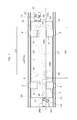
- the front and rear 2 One driven The first driven roller pair (8) having a narrow distance (D1) between the rollers (7a, 7b) and the second driven roller pair (10) having a wide distance (D2) between the two front and rear driven rollers (9a, 9b).
- At least two sets are provided with their positions shifted in a direction perpendicular to the traveling direction of the conveying traveling body, and the driven shafts (7a, 7b) of the first driven roller pair (8) are arranged as the screw shaft rows.
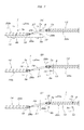
- the second screw shaft row 14 in this embodiment is supported at both ends by bearings 16 and linked to each other by transmission means 25 comprising a transmission shaft 24 having universal joints 23a and 23b at both ends.
- the two screw shafts 26a and 26b are connected and concentrically connected in series.
- the helical pitch of the screw shafts 26a and 26b is set based on a condition that is 1 / integer of the interval D2 between the two driven rollers 9a and 9b before and after the second driven roller pair 10.
- a screw shaft having a helical pitch MP (for example, 220 mm) of 1/7 of the interval D2 is employed for both of the two screw shafts 26a and 26b.
Landscapes
- Engineering & Computer Science (AREA)
- Mechanical Engineering (AREA)
- Chemical & Material Sciences (AREA)
- Combustion & Propulsion (AREA)
- Transportation (AREA)
- Rollers For Roller Conveyors For Transfer (AREA)
- Rehabilitation Tools (AREA)
- Forklifts And Lifting Vehicles (AREA)
Abstract
Description
3a,3b ガイドレール
6 ワーク支持台
7a,7b,9a,9b 被動ローラー
8 第一被動ローラー対
10 第二被動ローラー対
11,12 垂直軸体
13 第一スクリューシャフト列
14 第二スクリューシャフト列
19a,19b,23a,23b,28a,28b 自在継手
20,24,29 伝動軸
21,25,27 伝動手段
22a~22c,26a,26b スクリューシャフト
30 中心回転軸
31 螺旋状のスリット
32 スクリュー本体
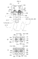
35a,35b 可動軸体
36 可動体
37a,37b 回転盤
38a,38b 門形ハンドル
39a,39b 係合部
40 垂直固定板
41a~43b 被係合部(水平スリット)
44 ロック手段
Claims (7)
- 同心状に直列して互いに等速で連動回転する複数本のスクリューシャフトから成るスクリューシャフト列が搬送用走行体の走行経路に沿って設けられ、搬送用走行体には、前記スクリューシャフトに係合する前後2つの被動ローラーが、前記スクリューシャフト間のスクリュー途切れ空間長さに対応した間隔で設けられたスクリュー駆動の搬送装置において、前記前後2つの被動ローラーとして、当該前後2つの被動ローラー間の間隔が狭い第一被動ローラー対と、当該前後2つの被動ローラー間の間隔が広い第二被動ローラー対の少なくとも二組が、搬送用走行体走行方向に対して直交する方向に位置をずらして設けられ、前記スクリューシャフト列として、前記第一被動ローラー対の各被動ローラーが係合する第一スクリューシャフト列と、前記第二被動ローラー対の各被動ローラーが係合する第二スクリューシャフト列が、搬送用走行体の走行経路に沿って交互に設けられ、第一スクリューシャフト列の各スクリューシャフトと第二スクリューシャフト列の各スクリューシャフトとは互いに等速で連動連結され、第一スクリューシャフト列と第二スクリューシャフト列との間の搬送用走行体走行方向のスクリュー途切れ空間長さは、上手側のスクリューシャフト列に係合する被動ローラー対の被動ローラー間の間隔と等しい、スクリュー駆動の搬送装置。
- 第一スクリューシャフト列と第二スクリューシャフト列との内、少なくとも一方のスクリューシャフト列には、このスクリューシャフト列に係合する前後2つの被動ローラーの間隔の整数分の1の条件で螺旋ピッチが設定された、送り速度の異なる複数のスクリューシャフトが組み込まれている、請求項1に記載のスクリュー駆動の搬送装置。
- 第一スクリューシャフト列と第二スクリューシャフト列とは、搬送用走行体の下側空間内で、当該搬送用走行体の巾方向の中央位置に対し左右対称に配設されている、請求項1又は2に記載のスクリュー駆動の搬送装置。
- 第一スクリューシャフト列の端部のスクリューシャフトと第二スクリューシャフト列と端部のスクリューシャフトとは、自在継手と斜めに配置された伝動軸とから成る伝動手段により互いに連動連結されている、請求項1~3の何れか1項に記載のスクリュー駆動の搬送装置。
- 第一被動ローラー対の先頭の被動ローラーと第二被動ローラー対の先頭の被動ローラーとは、搬送用走行体の走行方向に対して直交する方向に並列配置されている、請求項1~4の何れか1項に記載のスクリュー駆動の搬送装置。
- 各被動ローラーは、搬送用走行体の走行方向に直列し且つ係合するスクリューシャフトに対して直角向きに往復移動自在な2本の可動軸体によって搬送用走行体に支持された可動体に軸支され、前記2本の可動軸体を、被動ローラーがスクリューシャフトに係合する作用位置と被動ローラーがスクリューシャフトから離脱した非作用位置とでロックするロック手段が設けられている、請求項1~5の何れか1項に記載のスクリュー駆動の搬送装置。
- 前記ロック手段は、各可動軸体の端部に当該可動軸体の周りに回転自在に支持された回転盤と、この回転盤を回転操作するハンドルと、搬送用走行体側に前記回転盤に隣接するように配設され且つ被係合部が設けられた固定板と、前記回転盤の周辺に設けられた係合部とから成り、被動ローラーが作用位置と非作用位置にあるときに、前記回転盤の回転により前記係合部を前記被係合部に対して係脱操作出来るように構成された、請求項6に記載のスクリュー駆動の搬送装置。
Priority Applications (3)
| Application Number | Priority Date | Filing Date | Title |
|---|---|---|---|
| CN201380067875.7A CN104870291B (zh) | 2012-12-27 | 2013-09-26 | 螺旋驱动的搬运装置 |
| MX2015008338A MX362502B (es) | 2012-12-27 | 2013-09-26 | Aparato de transporte impulsado por tornillo. |
| US14/752,349 US9382074B2 (en) | 2012-12-27 | 2015-06-26 | Screw drive conveying apparatus |
Applications Claiming Priority (2)
| Application Number | Priority Date | Filing Date | Title |
|---|---|---|---|
| JP2012-285622 | 2012-12-27 | ||
| JP2012285622A JP5928724B2 (ja) | 2012-12-27 | 2012-12-27 | スクリュー駆動の搬送装置 |
Related Child Applications (1)
| Application Number | Title | Priority Date | Filing Date |
|---|---|---|---|
| US14/752,349 Continuation US9382074B2 (en) | 2012-12-27 | 2015-06-26 | Screw drive conveying apparatus |
Publications (1)
| Publication Number | Publication Date |
|---|---|
| WO2014103453A1 true WO2014103453A1 (ja) | 2014-07-03 |
Family
ID=51020555
Family Applications (1)
| Application Number | Title | Priority Date | Filing Date |
|---|---|---|---|
| PCT/JP2013/076002 Ceased WO2014103453A1 (ja) | 2012-12-27 | 2013-09-26 | スクリュー駆動の搬送装置 |
Country Status (5)
| Country | Link |
|---|---|
| US (1) | US9382074B2 (ja) |
| JP (1) | JP5928724B2 (ja) |
| CN (1) | CN104870291B (ja) |
| MX (1) | MX362502B (ja) |
| WO (1) | WO2014103453A1 (ja) |
Cited By (2)
| Publication number | Priority date | Publication date | Assignee | Title |
|---|---|---|---|---|
| US20170137228A1 (en) * | 2015-11-12 | 2017-05-18 | Daifuku Co., Ltd. | Conveying Device |
| CN112357481A (zh) * | 2020-11-06 | 2021-02-12 | 博众精工科技股份有限公司 | 一种托盘输送线体 |
Families Citing this family (3)
| Publication number | Priority date | Publication date | Assignee | Title |
|---|---|---|---|---|
| EP3397403A4 (en) * | 2015-12-29 | 2020-02-26 | Lighthouse Instruments, LLC | CONCENTRIC SHAFT DIVISION SYNCHRONIZATION SCREW SYSTEM |
| JP6745135B2 (ja) * | 2016-05-13 | 2020-08-26 | テクノダイナミックス株式会社 | 搬送装置 |
| CN112453567B (zh) * | 2020-12-01 | 2023-07-25 | 常德市鼎城奕通机械制造有限公司 | 一种用于钢管锯床的改进型自动送料机构 |
Citations (5)
| Publication number | Priority date | Publication date | Assignee | Title |
|---|---|---|---|---|
| US20100000843A1 (en) * | 2008-07-04 | 2010-01-07 | Hiroshi Nishikawa | Screw Driven Conveyance Device |
| JP2010047048A (ja) * | 2008-08-19 | 2010-03-04 | Tsubakimoto Chain Co | スクリュー駆動搬送台車およびスクリュー駆動搬送装置 |
| JP2010149730A (ja) * | 2008-12-25 | 2010-07-08 | Tsubakimoto Chain Co | スクリュー駆動搬送装置 |
| JP2011195261A (ja) * | 2010-03-19 | 2011-10-06 | Daifuku Co Ltd | 搬送用走行体利用の搬送装置 |
| JP2012035945A (ja) * | 2010-08-05 | 2012-02-23 | Daifuku Co Ltd | 搬送用走行体利用の搬送装置 |
-
2012
- 2012-12-27 JP JP2012285622A patent/JP5928724B2/ja active Active
-
2013
- 2013-09-26 CN CN201380067875.7A patent/CN104870291B/zh active Active
- 2013-09-26 WO PCT/JP2013/076002 patent/WO2014103453A1/ja not_active Ceased
- 2013-09-26 MX MX2015008338A patent/MX362502B/es active IP Right Grant
-
2015
- 2015-06-26 US US14/752,349 patent/US9382074B2/en active Active
Patent Citations (5)
| Publication number | Priority date | Publication date | Assignee | Title |
|---|---|---|---|---|
| US20100000843A1 (en) * | 2008-07-04 | 2010-01-07 | Hiroshi Nishikawa | Screw Driven Conveyance Device |
| JP2010047048A (ja) * | 2008-08-19 | 2010-03-04 | Tsubakimoto Chain Co | スクリュー駆動搬送台車およびスクリュー駆動搬送装置 |
| JP2010149730A (ja) * | 2008-12-25 | 2010-07-08 | Tsubakimoto Chain Co | スクリュー駆動搬送装置 |
| JP2011195261A (ja) * | 2010-03-19 | 2011-10-06 | Daifuku Co Ltd | 搬送用走行体利用の搬送装置 |
| JP2012035945A (ja) * | 2010-08-05 | 2012-02-23 | Daifuku Co Ltd | 搬送用走行体利用の搬送装置 |
Cited By (4)
| Publication number | Priority date | Publication date | Assignee | Title |
|---|---|---|---|---|
| US20170137228A1 (en) * | 2015-11-12 | 2017-05-18 | Daifuku Co., Ltd. | Conveying Device |
| CN107031665A (zh) * | 2015-11-12 | 2017-08-11 | 株式会社大福 | 输送装置 |
| US9938088B2 (en) * | 2015-11-12 | 2018-04-10 | Daifuku Co., Ltd. | Conveying device |
| CN112357481A (zh) * | 2020-11-06 | 2021-02-12 | 博众精工科技股份有限公司 | 一种托盘输送线体 |
Also Published As
| Publication number | Publication date |
|---|---|
| CN104870291B (zh) | 2017-03-29 |
| MX2015008338A (es) | 2015-11-09 |
| US20150291364A1 (en) | 2015-10-15 |
| US9382074B2 (en) | 2016-07-05 |
| JP2014125187A (ja) | 2014-07-07 |
| MX362502B (es) | 2019-01-22 |
| JP5928724B2 (ja) | 2016-06-01 |
| CN104870291A (zh) | 2015-08-26 |
Similar Documents
| Publication | Publication Date | Title |
|---|---|---|
| JP5928724B2 (ja) | スクリュー駆動の搬送装置 | |
| CN101434050B (zh) | 磨削机 | |
| JP2010159161A (ja) | 組付コンベア装置 | |
| CN215942345U (zh) | 一种金属管表面打磨装置 | |
| CN103998359B (zh) | 搬运装置 | |
| RU2611477C2 (ru) | Шпиндельный конвейер и установка для обработки обрабатываемых деталей с таковым | |
| JP2018100587A (ja) | レール運搬車 | |
| KR20110088734A (ko) | 화물운반용 리프트의 전방조향장치 | |
| KR20140014528A (ko) | 반송 시스템 | |
| CN106542291B (zh) | 环形输送带流水线 | |
| CN102114980A (zh) | 变轨机构 | |
| JP5320580B2 (ja) | スクリュー駆動の搬送装置 | |
| CN112193779A (zh) | 一种连续式转向输送机 | |
| JPH0733242A (ja) | ターンテーブルに固定された旋回レールと固定レールとの接合離反装置 | |
| JPH0649424U (ja) | 台車等の反転搬送装置 | |
| CN117505148A (zh) | 一种步进式地轨重型循环同步输送喷涂生产系统 | |
| JP5114320B2 (ja) | 搬送台車の駆動推進装置 | |
| CN115450078B (zh) | 一种长钢轨运输车 | |
| JP3384424B2 (ja) | 搬送設備 | |
| CN112429480A (zh) | 物料搬运系统 | |
| JPH0418977Y2 (ja) | ||
| JP4885588B2 (ja) | トレー横行機構及びこれを用いた機械式駐車設備 | |
| JP5114321B2 (ja) | 台車利用の搬送装置 | |
| KR100982501B1 (ko) | 평면왕복식 주차설비 | |
| JP4220948B2 (ja) | 無軌道式の自動走行台車 |
Legal Events
| Date | Code | Title | Description |
|---|---|---|---|
| 121 | Ep: the epo has been informed by wipo that ep was designated in this application |
Ref document number: 13868982 Country of ref document: EP Kind code of ref document: A1 |
|
| WWE | Wipo information: entry into national phase |
Ref document number: MX/A/2015/008338 Country of ref document: MX |
|
| WWE | Wipo information: entry into national phase |
Ref document number: IDP00201503922 Country of ref document: ID |
|
| NENP | Non-entry into the national phase |
Ref country code: DE |
|
| 122 | Ep: pct application non-entry in european phase |
Ref document number: 13868982 Country of ref document: EP Kind code of ref document: A1 |