WO2014092099A1 - 画像処理装置、放射線画像撮影システム、画像処理プログラム、及び画像処理方法 - Google Patents
画像処理装置、放射線画像撮影システム、画像処理プログラム、及び画像処理方法 Download PDFInfo
- Publication number
- WO2014092099A1 WO2014092099A1 PCT/JP2013/083129 JP2013083129W WO2014092099A1 WO 2014092099 A1 WO2014092099 A1 WO 2014092099A1 JP 2013083129 W JP2013083129 W JP 2013083129W WO 2014092099 A1 WO2014092099 A1 WO 2014092099A1
- Authority
- WO
- WIPO (PCT)
- Prior art keywords
- image
- radiation
- processing
- incident angle
- frequency component
- Prior art date
- Legal status (The legal status is an assumption and is not a legal conclusion. Google has not performed a legal analysis and makes no representation as to the accuracy of the status listed.)
- Ceased
Links
Images







Classifications
-
- A—HUMAN NECESSITIES
- A61—MEDICAL OR VETERINARY SCIENCE; HYGIENE
- A61B—DIAGNOSIS; SURGERY; IDENTIFICATION
- A61B6/00—Apparatus or devices for radiation diagnosis; Apparatus or devices for radiation diagnosis combined with radiation therapy equipment
- A61B6/02—Arrangements for diagnosis sequentially in different planes; Stereoscopic radiation diagnosis
- A61B6/025—Tomosynthesis
-
- G—PHYSICS
- G06—COMPUTING OR CALCULATING; COUNTING
- G06T—IMAGE DATA PROCESSING OR GENERATION, IN GENERAL
- G06T12/00—Tomographic reconstruction from projections
- G06T12/20—Inverse problem, i.e. transformations from projection space into object space
-
- A—HUMAN NECESSITIES
- A61—MEDICAL OR VETERINARY SCIENCE; HYGIENE
- A61B—DIAGNOSIS; SURGERY; IDENTIFICATION
- A61B6/00—Apparatus or devices for radiation diagnosis; Apparatus or devices for radiation diagnosis combined with radiation therapy equipment
- A61B6/02—Arrangements for diagnosis sequentially in different planes; Stereoscopic radiation diagnosis
- A61B6/03—Computed tomography [CT]
- A61B6/032—Transmission computed tomography [CT]
-
- A—HUMAN NECESSITIES
- A61—MEDICAL OR VETERINARY SCIENCE; HYGIENE
- A61B—DIAGNOSIS; SURGERY; IDENTIFICATION
- A61B6/00—Apparatus or devices for radiation diagnosis; Apparatus or devices for radiation diagnosis combined with radiation therapy equipment
- A61B6/50—Apparatus or devices for radiation diagnosis; Apparatus or devices for radiation diagnosis combined with radiation therapy equipment specially adapted for specific body parts; specially adapted for specific clinical applications
- A61B6/502—Apparatus or devices for radiation diagnosis; Apparatus or devices for radiation diagnosis combined with radiation therapy equipment specially adapted for specific body parts; specially adapted for specific clinical applications for diagnosis of breast, i.e. mammography
-
- A—HUMAN NECESSITIES
- A61—MEDICAL OR VETERINARY SCIENCE; HYGIENE
- A61B—DIAGNOSIS; SURGERY; IDENTIFICATION
- A61B6/00—Apparatus or devices for radiation diagnosis; Apparatus or devices for radiation diagnosis combined with radiation therapy equipment
- A61B6/52—Devices using data or image processing specially adapted for radiation diagnosis
- A61B6/5205—Devices using data or image processing specially adapted for radiation diagnosis involving processing of raw data to produce diagnostic data
-
- A—HUMAN NECESSITIES
- A61—MEDICAL OR VETERINARY SCIENCE; HYGIENE
- A61B—DIAGNOSIS; SURGERY; IDENTIFICATION
- A61B6/00—Apparatus or devices for radiation diagnosis; Apparatus or devices for radiation diagnosis combined with radiation therapy equipment
- A61B6/54—Control of apparatus or devices for radiation diagnosis
- A61B6/542—Control of apparatus or devices for radiation diagnosis involving control of exposure
-
- G—PHYSICS
- G06—COMPUTING OR CALCULATING; COUNTING
- G06T—IMAGE DATA PROCESSING OR GENERATION, IN GENERAL
- G06T2207/00—Indexing scheme for image analysis or image enhancement
- G06T2207/10—Image acquisition modality
- G06T2207/10004—Still image; Photographic image
-
- G—PHYSICS
- G06—COMPUTING OR CALCULATING; COUNTING
- G06T—IMAGE DATA PROCESSING OR GENERATION, IN GENERAL
- G06T2207/00—Indexing scheme for image analysis or image enhancement
- G06T2207/10—Image acquisition modality
- G06T2207/10072—Tomographic images
- G06T2207/10081—Computed x-ray tomography [CT]
Definitions
- the present invention relates to an image processing apparatus, a radiographic image capturing system, an image processing program, and an image processing method, and in particular, image processing for generating a tomographic image from a radiographic image captured by irradiating a subject with radiation at different angles.
- the present invention relates to an apparatus, a radiographic imaging system, an image processing program, and an image processing method.
- a radiographic imaging apparatus that performs radiography for the purpose of medical diagnosis.
- Examples of this type of radiographic imaging device include mammography that images a subject's breast for the purpose of early detection of breast cancer and the like.
- mammography a technique for performing tomosynthesis imaging in which radiation is applied to a breast of a subject at different angles is known.
- tomosynthesis imaging reconstructed from a plurality of radiographic images (hereinafter referred to as projection images) taken by irradiating a subject with different incident angles of radiation on the detection surface, and is applied to the detection surface at predetermined slice intervals. (Omitted) Generate parallel tomographic images.
- the angle when irradiating radiation is limited, so that, for example, even if the tomographic image is simply reconstructed by superimposing the projected images by the back projection method, no object originally exists.
- a virtual image of the object may appear in the area. More specifically, back projection may cause a virtual image to appear in a region where the object originally does not exist in the tomographic image at a slice position different from the tomographic image at the slice position where the object exists. If the virtual image is too conspicuous, it will be difficult to confirm the object of interest. A similar situation occurs when tomographic image reconstruction is performed by other methods.
- a tomographic image can be reconstructed by back projecting from a projection image that has been uniformly filtered by applying the FBP method (Filtered Back Projection method), which is a typical method of CT reconstruction.
- FBP method Frtered Back Projection method
- the virtual image in the depth direction can be reduced to some extent, but in the case of tomosynthesis imaging, if the filtering process is performed uniformly, the density of the subject image of the tomographic image may be far from the projected image.
- the present invention when reconstructing a tomographic image from a projection image obtained by tomosynthesis imaging, suppresses a significant decrease in the concentration of the object of interest, and at the same time, an artifact in a tomographic image at a slice position where the object of interest does not actually exist.
- An image processing apparatus, a radiographic imaging system, an image processing method, and an image processing program are provided.
- the subject between the radiation detector and the radiation irradiating unit is moved while moving the radiation irradiating unit, and the incident angle of the radiation irradiated from the radiation irradiating unit is varied.
- Acquisition means for acquiring a plurality of projection images taken at different incident angles, and processing means for performing frequency processing to attenuate the low-frequency component of the projection image having an incident angle equal to or greater than a first threshold relative to the high-frequency component;
- a tomographic image generation means for generating a tomographic image of a subject by reconstructing the projection image having an incident angle less than the first threshold and the frequency-processed projection image.
- the tomographic image is reconstructed by performing frequency processing in which the low-frequency component of the projection image whose incident angle is equal to or greater than the first threshold is relatively attenuated with respect to the high-frequency component, so The low-frequency component of the projected image is not attenuated compared to the high-frequency component, and the low-frequency component of the projected image whose incident angle is the first threshold value or more can be attenuated compared to the high-frequency component. While suppressing the decrease, the artifact in the tomographic image at the slice position where the object of interest does not actually exist can be made inconspicuous.
- the processing means as frequency processing, attenuates a low frequency component of a projection image whose incident angle is equal to or greater than the first threshold value, and emphasizes a high frequency component of the projection image whose incident angle is equal to or greater than the first threshold value. You may make it perform at least one of a process.
- the processing means when the processing means performs frequency processing for relatively attenuating the low frequency component, the degree of the relative attenuation of the low frequency component is increased as the incident angle increases. Good.
- the tomographic image generation unit reconstructs the tomographic image by assigning a weight according to the incident angle to the projected image whose incident angle is less than the first threshold and the projected image subjected to frequency processing. You may make it do.
- the processing means may further perform frequency processing that emphasizes a low frequency component of a projection image whose incident angle is less than a second threshold relative to a high frequency component.
- the processing means when the processing means performs frequency processing for relatively enhancing low frequency components, the degree of relatively enhancing low frequency components as the incident angle decreases is increased. Good.
- the image processing apparatus varies the incident angle of the radiation irradiated from the radiation irradiating unit with respect to the subject between the radiation detector and the radiation irradiating unit while moving the radiation irradiating unit.
- acquiring means for acquiring a plurality of projection images taken at different incident angles, and increasing the degree as the incident angle increases to relatively attenuate the low-frequency component of the projection image relative to the high-frequency component.
- the degree of interest increases as the incident angle increases, and the tomographic image is reconstructed by performing frequency processing that attenuates the low-frequency component of the projection image relative to the high-frequency component. It is possible to make the artifact in the tomographic image at the slice position where the object of interest does not actually exist inconspicuous while suppressing the extreme decrease in the density of the image.
- the present invention performs a projection process along a predetermined direction on a laminated image obtained by laminating a plurality of tomographic images generated by the tomographic image generating means, or responds along a predetermined direction.
- a two-dimensional image generation means for generating a two-dimensional image by performing addition processing for adding pixel values of pixels may be further provided.
- a radiographic imaging system includes a radiation detector and a radiation irradiation unit, and irradiates from a radiation irradiation unit to a subject between the radiation detector and the radiation irradiation unit while moving the radiation irradiation unit.
- Radiographic image capturing apparatus that captures a plurality of projected images at different incident angles by irradiating radiation with different incident angles of the radiation to the subject, and tomographic images from the plurality of projected images captured by the radiographic image capturing apparatus And the above-described image processing apparatus.
- An image processing program relates to a computer, an incident angle of radiation irradiated from a radiation irradiation unit while moving the radiation irradiation unit with respect to a subject between the radiation detector and the radiation irradiation unit. And obtaining means for acquiring a plurality of projection images photographed at different incident angles, and frequency processing for attenuating a low frequency component of a projection image having an incident angle equal to or greater than a first threshold relative to a high frequency component.
- This is a program for functioning as processing means to perform and tomographic image generation means for generating a tomographic image of a subject by reconstructing from a projection image whose incident angle is less than a first threshold and a frequency processed projection image.
- An image processing program relates to a computer, the incident angle of the radiation irradiated from the radiation irradiating unit while moving the radiation irradiating unit to the subject between the radiation detector and the radiation irradiating unit.
- Acquisition means for acquiring a plurality of projection images taken at different incident angles, the degree is increased as the incident angle is increased, and the low-frequency component of the projection image is relative to the high-frequency component.
- This is a program for functioning as processing means for performing frequency processing for attenuation and tomographic image generation means for generating a tomographic image of a subject by reconstructing from the projection image subjected to frequency processing by the processing means.
- the image processing method varies the incident angle of the radiation irradiated from the radiation irradiator with respect to the subject between the radiation detector and the radiation irradiator while moving the radiation irradiator. Acquiring a plurality of projection images taken at different incident angles, and performing frequency processing to attenuate the low-frequency component of the projection image whose incident angle is equal to or greater than the first threshold relative to the high-frequency component. Generating a tomographic image of a subject by reconstructing from a projection image whose incident angle is less than a first threshold and a frequency-processed projection image.
- the image processing method varies the incident angle of the radiation irradiated from the radiation irradiating unit with respect to the subject between the radiation detector and the radiation irradiating unit while moving the radiation irradiating unit.
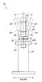
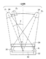
- FIG. 1 It is a top view which shows an example of a structure of the radiographic imaging apparatus of embodiment. It is a figure which shows an example of the structure at the time of imaging
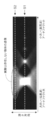
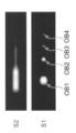
- FIG. 6A shows a case where a tomographic image is reconstructed without performing frequency processing on any of the photographed projection images and stacked in the Z-axis direction (depth direction) corresponding to the slice position of each tomographic image. It is sectional drawing parallel to the XZ plane in the position 150 of the Y-axis direction.
- FIG. 6B is a tomographic image corresponding to slice positions S1 and S2 in FIG. 6B. It is explanatory drawing explaining the reason which an artifact generate
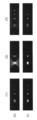
- the tomographic image corresponding to the position S1 parallel to the detection surface of the radiation detector at the position in the depth direction where the object of interest exists It is a figure which shows the combination with the image corresponding to the cross section S2 along a depth direction for every kind of frequency processing. It is explanatory drawing explaining the case where frequency processing is not performed. It is explanatory drawing explaining the case where the frequency process which attenuates a low frequency component is performed to the projection image with a large incident angle. It is a flowchart which shows the flow of a tomographic image / two-dimensional image generation processing program. It is a schematic diagram explaining the maximum value projection process. It is explanatory drawing for demonstrating an artifact and the influence on a two-dimensional image.
- the radiographic image capturing apparatus 10 of the present embodiment captures the breast N of the subject W with radiation (for example, X-rays) in the standing state where the subject W stands.
- An apparatus for example, called mammography.
- the near side near the subject W is defined as the front side of the radiographic image capturing apparatus 10
- the subject W faces the radiographic image capturing apparatus 10.
- the far side away from the subject W in this case is the rear side of the radiographic imaging device 10
- the left-right direction of the subject W when the subject W faces the radiographic imaging device 10 is the left-right direction of the radiographic imaging device 10. (See each arrow in FIGS. 1 and 2).
- the imaging target of the radiation image capturing apparatus 10 is not limited to the breast N, and may be, for example, another part of the body or an object.
- the radiographic image capturing apparatus 10 may be an apparatus that captures the breast N of the subject W in a sitting position in which the subject W is sitting on a chair (including a wheelchair) or the like. Any device may be used as long as the breast N of the subject W can be separately photographed while standing.
- the radiographic image capturing apparatus 10 includes a measurement unit 12 having a substantially C-shaped side view provided on the front side of the apparatus, and a base unit 14 that supports the measurement unit 12 from the rear side of the apparatus. ing.
- the measuring unit 12 presses the breast N between the imaging surface 22 on which the planar imaging surface 20 that contacts the breast N of the subject W in the standing state is formed and the imaging surface 20 of the imaging table 22.
- a holding unit 28 that supports the imaging table 22 and the compression plate 26. Note that a member that transmits radiation is used for the compression plate 26.
- the measurement unit 12 is provided with a radiation source 30 such as a tube (see FIG. 4), a radiation irradiation unit 24 that irradiates radiation for inspection from the radiation source 30 toward the imaging surface 20, and a holding unit 28. Is provided with a support part 29 that is separated and supports the radiation irradiation part 24.
- a radiation source 30 such as a tube (see FIG. 4)
- a radiation irradiation unit 24 that irradiates radiation for inspection from the radiation source 30 toward the imaging surface 20
- a holding unit 28 Is provided with a support part 29 that is separated and supports the radiation irradiation part 24.
- the measuring unit 12 is provided with a rotating shaft 16 that is rotatably supported by the base unit 14.
- the rotation shaft 16 is fixed with respect to the support portion 29, and the rotation shaft 16 and the support portion 29 rotate together.
- the holding unit 28 can be switched between a state in which the rotation shaft 16 is connected and rotates integrally, and a state in which the rotation shaft 16 is separated and idles. Specifically, gears are provided on the rotating shaft 16 and the holding portion 28, respectively, and the meshing state and the non-meshing state of the gears are switched.
- various mechanical elements can be used for switching between transmission / non-transmission of the rotational force of the rotating shaft 16.
- the holding unit 28 supports the imaging table 22 and the radiation irradiation unit 24 so that the imaging surface 20 and the radiation irradiation unit 24 are separated from each other by a predetermined distance, and the interval between the compression plate 26 and the imaging surface 20 is variable.
- the compression plate 26 is slidably held.
- the imaging surface 20 with which the breast N abuts is made of, for example, carbon from the viewpoint of radiolucency and strength.
- a radiation detector 42 for detecting radiation that is irradiated with radiation that has passed through the breast N and the imaging surface 20 is disposed inside the imaging table 22. The radiation detected by the radiation detector 42 is visualized and a radiation image is generated.
- the radiographic image capturing apparatus 10 irradiates the breast N as a subject with different incident angles with respect to the detection surface of the radiation detector 42 (changes), and emits radiation at different incident angles. It is an apparatus that can perform photographing.
- the incident angle refers to an angle formed by the normal line of the detection surface of the radiation detector 42 and the radiation axis.
- the detection surface of the radiation detector 42 is a surface substantially parallel to the imaging surface 20.
- FIGS. 2 and 3 respectively show the posture of the radiation image capturing apparatus 10 at the time of imaging and the position of the radiation irradiation unit 24 at the time of imaging. As shown in FIGS. 2 and 3, the imaging is performed by supporting the radiation irradiating unit 24 and inclining a support unit 29 that supports the imaging table 22 via the holding unit 28.
- the incident angle with respect to the detection surface of the radiation detector 42 with respect to the breast N is within a predetermined range (for example, a range of ⁇ 20 degrees with respect to the normal of the detection surface).
- a predetermined range for example, a range of ⁇ 20 degrees with respect to the normal of the detection surface.
- tomosynthesis imaging the rotating shaft 16 is idled with respect to the holding unit 28, and the imaging table 22 and the compression plate 26 do not move.
- the support portion 29 rotates, only the radiation irradiation portion 24 moves in an arc shape.
- the position of the radiation irradiation unit 24 is moved from the angle ⁇ by a predetermined angle ⁇ , and imaging is performed at n positions P1 to Pn. .
- incident angle the incident angle of radiation with respect to the normal direction of the detection surface of the radiation detector 42 is simply referred to as “incident angle”.
- the radiation N is irradiated n times on the breast N of the subject W, so that the dose of radiation is reduced so that the exposure dose does not increase, for example, n times
- the radiation is irradiated so as to have a dose comparable to that of general two-dimensional imaging (normal imaging in which the subject is irradiated with radiation from a fixed position without moving the radiation source 30).
- both CC (Cranio & Caudal: head-to-tail direction) imaging and MLO (Mediolateral-Oblique) imaging are performed on the breast N.
- CC imaging the posture of the holding unit 28 is adjusted so that the imaging surface 20 faces upward, and the support unit 29 is positioned so that the radiation irradiation unit 24 is positioned above the imaging surface 20. The posture is adjusted. Thereby, radiation is irradiated from the radiation irradiation unit 24 to the breast N from the head side to the foot side of the standing subject W, and CC imaging is performed.
- the posture of the holding unit 28 is adjusted in a state where the imaging table 22 is rotated 45 ° or more and less than 90 ° compared to CC imaging, and the side wall angle of the imaging table 22 on the front side of the apparatus is adjusted. Positioning is performed so that the axilla of the subject W is applied to the part 22A. Thereby, the radiation is irradiated from the radiation irradiation unit 24 to the breast N from the axial center side of the body of the subject W to the outside, and MLO imaging is performed.
- a chest wall surface 25 is formed on the surface of the imaging table 22 on the front side of the apparatus so as to abut the chest portion below the breast N of the subject W during imaging.
- the chest wall surface 25 is flat.
- the breast N is pressed and fixed by the compression plate 26 in a state where the breast N is in contact with the imaging surface 20 of the imaging table 22.
- the radiation incident angle with respect to the normal direction of the detection surface of the radiation detector 42 that is parallel to the imaging surface 20 and the incidence of radiation on the breast N The angle is equal.
- the incident angle of the radiation with respect to the breast N is a straight line connecting the radiation source 30 with a predetermined point inside the breast N (for example, the center point of the part in contact with the imaging surface 20 of the breast N). And the gravitational direction.
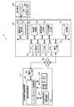
- FIG. 4 shows a block diagram of an example of the configuration of the radiographic imaging system 5 of the present embodiment.
- the radiographic image capturing system 5 of this embodiment includes a radiographic image capturing device 10, an image processing device 50, and a display device 80.
- the radiation image capturing apparatus 10 includes a radiation irradiation unit 24, a radiation detector 42, an operation panel 44, an image capturing apparatus control unit 46, and a communication I / F unit 48.
- the imaging device control unit 46 has a function of controlling the overall operation of the radiographic imaging device 10, and includes a memory including a CPU (Central Processing Unit), a ROM (Read Only Memory), and a RAM (Random Access Memory), an HDD It is configured with a non-volatile storage unit such as (Hard Disk Drive) or flash memory.
- the imaging device control unit 46 is connected to the radiation irradiation unit 24, the radiation detector 42, the operation panel 44, and the communication I / F unit 48.
- the imaging apparatus control unit 46 When receiving an irradiation instruction from the operator through the operation panel 44 (exposure switch), the imaging apparatus control unit 46 is provided in the radiation irradiation unit 24 in accordance with an imaging menu (described in detail later) set based on the specified exposure condition. Radiation is applied to the imaging surface 20 from the received radiation source 30.
- the radiation source 30 emits cone beam radiation (for example, a conical X-ray beam).
- the radiation detector 42 receives the irradiation of the radiation carrying the image information, records the image information, and outputs the recorded image information.
- a radiation sensitive layer is arranged to convert the radiation into digital data. And output as an FPD (Flat Panel Detector).
- the radiation sensitive layer can be disposed substantially parallel to the imaging surface 20.
- the radiation detector 42 outputs image information indicating a radiation image to the imaging device controller 46.
- the radiation detector 42 receives image radiation that has passed through the breast N to obtain image information indicating a radiation image.
- the operation panel 44 has a function for setting various operation information including shooting conditions, various operation instructions, and the like.
- the imaging conditions set on the operation panel 44 include information such as tube voltage, tube current, exposure conditions including irradiation time, and posture information.
- the posture information specified on the operation panel 44 includes information representing an imaging position (including the incident angle) when imaging is performed with radiation incident on the breast N at a plurality of incident angles.
- RIS Radiology Information System
- a radiation information system a system that manages information such as medical treatment and diagnosis using radiation
- a storage unit may be stored in advance in a storage unit.
- the imaging apparatus control unit 46 emits radiation from the radiation irradiation unit 24 according to the imaging menu set based on the set various types of information (breast N). Radiation images are taken by irradiation.
- the imaging device control unit 46 adjusts the posture of the holding unit 28 so that the imaging surface 20 faces upward, and the radiation irradiation unit 24 applies to the imaging surface 20.
- the posture of the support part 29 is adjusted to a state positioned above.
- the imaging apparatus control unit 46 rotates the support unit 29 to move the radiation irradiation unit 24 in an arc shape from the angle ⁇ to the angle ⁇ based on the imaging conditions. Radiation is emitted from a radiation source 30 provided at 24. As a result, n radiation images having different radiation incident angles are obtained.
- the communication I / F unit 48 is a communication interface having a function for transmitting and receiving a radiographic image and various information captured between the radiographic image capturing apparatus 10 and the image processing apparatus 50 via the network 49. is there.
- the image processing apparatus 50 has a function of generating a tomographic image reconstructed from the radiographic image acquired from the radiographic image capturing apparatus 10, and performs image processing for a doctor or the like to observe an object of interest such as a tumor. It has a function for images.
- a person such as a doctor who observes a captured radiographic image or generated tomographic image or diagnoses a tumor or the like is referred to as a user, and the radiation detector 42 performs radiation tomography in the radiographic imaging apparatus 10 through tomosynthesis imaging.
- a radiographic image obtained by detecting the above is called a “projection image”.
- the image processing apparatus 50 includes a CPU 52, a ROM 54, a RAM 56, an HDD 58, a communication I / F unit 60, an image display instruction unit 62, an instruction reception unit 64, a frequency processing unit 66, a tomographic image generation unit 68, a two-dimensional image generation unit 70, And a storage unit 74. These are connected to each other through a bus 75 such as a control bus or a data bus so that information can be exchanged.
- a bus 75 such as a control bus or a data bus so that information can be exchanged.
- the CPU 52 controls the entire image processing apparatus 50. Specifically, the CPU 52 executes a program 55 (each of tomographic image generation processing and tomographic image / two-dimensional image generation processing to be described later) stored in the ROM 54.
- the program is controlled by executing a program including In the present embodiment, the program 55 is stored in advance. However, the present invention is not limited to this.
- the program 55 is stored in a recording medium such as a CD-ROM or a removable disk, and the ROM 54 or the like is recorded from the recording medium. It may be installed on the ROM 54 or the like from an external device via a communication line such as the Internet.
- the RAM 56 secures a work area when the CPU 52 executes the program 55.
- the HDD 58 stores and holds various data.
- the communication I / F unit 60 is a communication interface having a function for transmitting and receiving a radiographic image and various information captured between the image processing apparatus 50 and the radiographic image capturing apparatus 10 via the network 49. is there.
- the image display instruction unit 62 has a function of instructing the display 82 of the display device 80 to display a radiation image.
- the display device 80 has a function of displaying a captured radiographic image, and includes a display 82 on which a radiographic image is displayed and an instruction input unit 84.
- the instruction input unit 84 may be, for example, a touch display, a keyboard, and a mouse.
- the instruction input unit 84 allows a user (for example, a doctor or the like) to input an instruction regarding the display of a radiation image.
- the instruction receiving unit 64 has a function of receiving an instruction from the user input by the instruction input unit 84 of the display device 80.
- the frequency processing unit 66 performs frequency processing according to the incident angle when the projection image is captured. More specifically, frequency processing is performed to attenuate a low frequency component of a projection image having an incident angle equal to or greater than a threshold (hereinafter referred to as a first threshold) relative to a high frequency component.
- a threshold hereinafter referred to as a first threshold
- the value of the first threshold is set in advance.
- the spatial frequency range including an object larger than the size of the object of interest to be interpreted by the user is regarded as a low frequency region, and the object included in the low frequency region is regarded as a low frequency component.
- a spatial frequency range higher than the upper limit value of the low frequency region is regarded as a high frequency region, and an object included in the high frequency region is regarded as a high frequency component.
- a general size of calcification (for example, 300 ⁇ m) is applied as the size of the object of interest, but the present invention is not limited to this, and for example, a mass or the like Other sizes of interest may be applied.
- the frequency processing unit 66 applies the low frequency component of the projection image having the incident angle equal to or greater than the first threshold to the high frequency component according to the enhancement coefficient indicating the degree of enhancement. Frequency processing to relatively attenuate. Further, in the frequency processing unit 66 of the present embodiment, the frequency component in the range of the spatial frequency to be processed increases as the enhancement coefficient exceeds a predetermined threshold (1.0 in the present embodiment). The degree of emphasizing the frequency component increases, and the degree of attenuation of the frequency component increases as the value decreases below the threshold.
- the frequency processing unit 66 first performs a process of reducing the sharpness of the projected image by changing the degree of reducing the sharpness of the image, thereby lowering the sharpness of the projected image.
- a plurality of images having different sharpness levels (hereinafter referred to as “non-sharp images”) are generated.
- filter processing using a Gaussian filter is applied as processing for reducing the sharpness.
- the present invention is not limited to this.
- other processing such as filter processing using a moving average filter may be used.
- a known method may be applied.
- the frequency processing unit 66 uses the projection image and each non-sharp image to perform conversion using a predetermined conversion function on each difference between the images having the closest sharpness, and after the conversion An image obtained by integrating the differences is generated. Then, the frequency processing unit 66 adds an image obtained by adding the image obtained by performing enhancement and attenuation processing according to a preset enhancement coefficient to the image obtained by the integration and the projection image, to the frequency processing. Is generated as an image.
- the spatial frequency range and the emphasis coefficient applied when the frequency processing unit 66 performs frequency processing on the projection image may be stored in advance in storage means such as the ROM 54, or the instruction input unit 84 may be used. Via the communication I / F unit 60 or by an external device or the like. Since the above frequency processing is a conventionally known technique, further detailed explanation is omitted.
- the tomographic image generation unit 68 reconstructs a projection image whose incident angle is less than the first threshold and a projection image frequency-processed by the frequency processing unit 66, and generates a tomographic image parallel to the imaging surface 20 at a predetermined slice interval. It has the function to do. In this embodiment, “parallel” is used, but it also includes substantially parallel.
- the tomographic image generation unit 68 generates a tomographic image at a predetermined slice interval from a plurality of projection images captured by moving the radiation irradiation unit 24 (radiation source 30) to the positions P1, P2, P3,. Generate. Note that the position at which the object of interest is projected onto the radiation image differs depending on the incident angle of radiation with respect to the imaging surface 20. Therefore, the tomographic image generation unit 68 acquires imaging conditions when the radiographic image is captured from the radiographic image capturing apparatus 10, and based on the incident angle of the radiation included in the imaging conditions, the interest among the plurality of radiographic images. The movement amount of the object is calculated, and the tomographic image is reconstructed based on a known reconstruction method such as a shift addition method.
- a known reconstruction method such as a shift addition method.
- a conventionally known CT reconstruction method can be used in addition to the shift addition method.
- an FBP method Frtered Back Projection method
- the FBP method is a reconstruction method in which tomographic parallel plane tomographic scanning is regarded as part of cone beam CT scanning and the filter back projection method is extended.
- an iterative reconstruction method described in JP2011-125698A can also be used. This iterative reconstruction method is also a reconstruction method for CT, but can be applied to reconstruction at the time of tomosynthesis imaging as well as the FBP method.
- a tomographic image is reconstructed by performing addition processing such as shift addition or back projection after performing frequency processing on the projection image that requires frequency processing.
- the two-dimensional image generation unit 70 performs a projection process along a predetermined direction on a stacked image (three-dimensional image) obtained by stacking a plurality of tomographic images generated by the tomographic image generation unit 68 or determines in advance.
- a two-dimensional image is generated by performing addition processing for adding corresponding pixel values along the specified direction.
- the 2D image generated by the 2D image generation unit 70 will be briefly described.
- tomosynthesis imaging is being widely recognized, but tomographic images obtained by tomosynthesis imaging are often used as a function to assist the radiographic image obtained by the above-described two-dimensional imaging. This is because doctors and the like are accustomed to the radiographic image taken by normal two-dimensional imaging, the radiographic image has a density different from that of the tomographic image, and can grasp the whole at once.
- diagnosis is often performed by combining two-dimensional imaging and tomosynthesis imaging, and combining a radiographic image obtained by two-dimensional imaging and a tomographic image obtained by tomosynthesis imaging.
- a two-dimensional image generation unit 70 is provided in the image processing apparatus 50. Provided.
- the two-dimensional image generation unit 70 may be configured to operate when a two-dimensional image generation is instructed by the instruction input unit 84. Further, the image processing apparatus 50 may be configured such that the two-dimensional image generation unit 70 is not provided.
- Each of the frequency processing unit 66, the tomographic image generation unit 68, and the two-dimensional image generation unit 70 includes hardware, for example, a general electronic circuit, an ASIC (Application Specific Integrated Circuit), or an FPGA (Field Programmable Gate). It can be realized by hardware configured by (Array) or the like.
- the storage unit 74 stores a projection image captured by the radiographic image capturing apparatus 10, a tomographic image generated by the tomographic image generation unit 68, image information representing each of the two-dimensional images generated by the two-dimensional image generation unit 70, and the like.
- it is a mass storage device such as a hard disk.
- the storage unit 74 also stores imaging conditions (such as an incident angle of radiation) when the radiographic image capturing apparatus 10 captures a radiographic image.
- the radiographic image capturing apparatus 10 When performing radiographic image capturing, the radiographic image capturing apparatus 10 performs capturing according to the capturing menu when the capturing menu is set.
- the radiographic image capturing apparatus 10 adjusts the posture of the holding unit 28 so that the imaging surface 20 faces upward as shown in FIG.
- the attitude of the support portion 29 is adjusted to a state positioned above the imaging surface 20.
- the test subject W brings the breast N into contact with the imaging surface 20 of the radiographic imaging device 10.
- the radiographic imaging device 10 moves the compression plate 26 toward the imaging surface 20 when an operation instruction is given to the operation panel 44 from the operator in this state.
- the radiographic imaging apparatus 10 when the radiographic imaging apparatus 10 according to the present embodiment receives an imaging instruction for performing tomosynthesis imaging in the operation panel 44, as shown in FIG.
- the part 24 is moved arcuately from the angle ⁇ by a predetermined angle ⁇ , and the radiation irradiating part 24 is irradiated with radiation based on imaging conditions at n positions P1 to Pn.
- the radiation individually irradiated from the radiation irradiation unit 24 reaches the radiation detector 42 after passing through the breast N.
- the radiation detector 42 When the radiation detector 42 is irradiated with radiation, the radiation detector 42 outputs image information indicating a projected image by the irradiated radiation to the imaging device control unit 46, respectively. As described above, when radiation irradiation is performed at n positions P1 to Pn of the radiation irradiation unit 24, image information of n projection images is output to the imaging device control unit 46. .
- the imaging device control unit 46 outputs the input image information to the image processing device 50. As described above, when the radiation irradiation unit 24 is irradiated with radiation at n positions P1 to Pn, the CPU of the imaging device control unit 46 obtains image information of n projection images. The image is output to the image processing apparatus 50.
- the image processing device 50 performs tomographic image generation processing for reconstructing a tomographic image and displaying it on the display device 80 after performing frequency processing of the projection image.
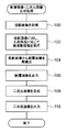
- FIG. 5 is a flowchart showing the flow of a tomographic image generation processing program executed by the CPU 52 of the image processing apparatus 50 of the present embodiment.
- step 100 the CPU 52 acquires image information of a plurality of (here, n) projection images from the radiographic image capturing apparatus 10.
- the CPU 52 controls the frequency processing unit 66 to execute frequency processing according to the incident angle.
- the frequency processing unit 66 performs frequency processing that relatively attenuates the low-frequency component of the projected image having an incident angle at the time of shooting equal to or greater than the first threshold with respect to the high-frequency component.
- the enhancement coefficient for the high frequency component is set to 1.0 and the enhancement coefficient for the low frequency component is set to less than 1.0. It is assumed that processing for enhancing low frequency components (hereinafter referred to as low frequency component attenuation processing) is performed without performing processing for enhancing high frequency components. Note that the low-frequency component attenuation processing is not performed for the projection image whose incident angle is less than the first threshold (the degree of attenuation of the low-frequency component is set to 0).
- the enhancement coefficient used here is a value that allows the object of interest to be visually recognized when a tomographic image obtained as a result is interpreted according to the size of the object of interest to be interpreted. It is possible to apply a value obtained in advance by an experiment using the actual machine or a computer simulation based on the design specification of the radiation image capturing apparatus 10.
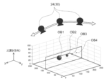
- FIG. 6A is a diagram schematically showing an example of tomosynthesis imaging.
- the Z axis indicates coordinate values (distance from the detection surface) in a direction perpendicular to the detection surface.
- the radiation irradiating unit 24 is moved to irradiate four imaging objects OB1 to OB4 from three places. Of the four shooting targets, OB1 has the largest size and OB4 has the smallest size.
- FIG. 6B shows the Y-axis position when the tomographic image is reconstructed without performing frequency processing on any of the photographed projection images and stacked in the depth direction corresponding to the slice position of each tomographic image.
- 6 is a cross-sectional view parallel to the XZ plane at 150 (see also FIG. 6A).
- FIG. 6C is a tomographic image corresponding to the slice positions S1 and S2 in FIG. 6B.
- S1 corresponds to the position where OB1 actually exists, and the image of OB1 clearly appears in the tomographic image of S1.
- S2 is originally a position where OB1 does not exist, a virtual image (artifact) of the object OB1 is reflected in the tomographic image of S2.
- a larger virtual image is generated in the depth direction as the size of the object increases.
- the image is converted to the spatial frequency domain, the image of the large object is converted as a low frequency component, and the image of a small (fine) object is converted as a high frequency component.
- an image is represented by a region, it can be seen that the artifact in the depth direction becomes larger as the object of the low frequency component, and the artifact in the depth direction becomes smaller as the object of the high frequency component.
- FIG. 8B when the reconstructed tomographic images are stacked in the depth direction corresponding to each slice position, the position is parallel to the detection surface of the radiation detector 42 at the position in the depth direction where the object of interest exists.
- a combination of a corresponding tomographic image and an image corresponding to the cross section S2 along the depth direction is shown (see also FIG. 8A).
- combinations of three patterns from (1) to (3) are shown.
- (1) in FIG. 8B is an ideal combination of images to be originally projected.
- (2) is a combination of images when all the projected images are uniformly reconstructed by filtering with a low-frequency component transmission filter (LPF: low-pass filter).
- LPF low-pass filter
- HPF high-pass filter
- the structure of rough fat, mammary gland, lesion (tumor), and mammary gland that are the main target of interpretation (interest) can be classified into low-frequency components that are somewhat large in size. Therefore, in the present embodiment, the frequency that does not perform uniform frequency processing on all the projected images, but rather attenuates the low frequency component of the projected image whose incident angle is equal to or greater than the first threshold relative to the high frequency component. By performing the processing, it is possible to suppress the image density of the object of interest from being extremely lowered, and to make the artifact of the tomographic image in which the object of interest does not originally exist inconspicuous.
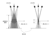
- FIG. 9A is an explanatory diagram for explaining a case where frequency processing is not performed on each projection image
- FIG. 9B is an explanatory diagram for explaining a case where low frequency component attenuation processing is performed on a projection image having a large incident angle. is there.
- the radiation irradiation unit 24 is moved to irradiate the subject from three locations (1), (2), and (3), and three projected images are taken.
- (1) is a position where the incident angle is 0, and (2) and (3) are positions where the incident angle is equal to or greater than the first threshold.
- the portion where the irradiation ranges of a plurality of radiations irradiated from different directions overlap is illustrated in such a manner that the density increases according to the overlapping state.
- cone beam radiation is emitted.
- parallel radiation is emitted from each position.
- the subject image when the subject is irradiated with radiation from the position (1), the subject image is projected onto the area G1 of the projection image.
- the subject image When the subject is irradiated with radiation from the position (2), the subject image is projected onto the area G2 of the projection image.
- the subject image When the subject is irradiated with radiation from the position (3), the subject image is projected onto the area G3 of the projection image. Therefore, when a tomographic image corresponding to a slice position where no subject originally exists is reconstructed, a virtual image is generated by G2 and G3.
- the projection range of the subject image is limited to the area of g2. Is done.
- the projection range of the subject image is limited to the area g3. That is, as compared with G2 and G3 in FIG. 9A, only the contour portion of the subject image remains, and the inner density is attenuated.
- the density of the virtual image is diminished due to the attenuation of the low frequency component.
- the low-frequency component attenuation processing is not performed on the projected image obtained by irradiating the subject with radiation from the position (1) (the attenuation level is set to 0). It is suppressed that the density
- processing for enhancing high frequency components may be performed without performing processing for reducing low frequency components.
- both processing for attenuating low frequency components and processing for enhancing high frequency components may be performed.
- a process for attenuating both the low-frequency component and the high-frequency component may be performed.
- the degree of attenuation of the low-frequency component may be D1, and the degree of attenuation of the high-frequency component may be D2 smaller than D1.
- the processing for emphasizing both the low-frequency component and the high-frequency component may be performed, and at this time, the enhancement degree of the low-frequency component may be set as D3 and the enhancement degree of the high-frequency component may be processed as D4 larger than D3.
- the frequency processing for relatively attenuating the low-frequency component is performed on the projection image whose incident angle is equal to or greater than the first threshold value.
- the first threshold value is, for example, the radiation irradiation unit 24 (radiation source 30). ) Can be set in advance according to the movement interval and the like.
- the frequency processing unit 66 may perform frequency processing for attenuating each low frequency component on a projection image other than the projection image having the smallest incident angle. In this case, of the incident angles at the time of photographing a plurality of projected images, the smallest incident angle is a1, and the second smallest incident angle is a2.
- One threshold can be set.
- the position of the radiation source 30 at the time of tomosynthesis imaging is set in advance, instead of setting the first threshold value itself, the first of the plurality of positions of the radiation source 30 at the time of tomosynthesis imaging is used. You may make it set the position of the radiation source 30 used as the incident angle more than a threshold value. What is necessary is just to implement the process which attenuates a low frequency component to the projection image obtained by irradiating a radiation from the set position.
- step 104 the CPU 52 controls the tomographic image generation unit 68 to reconstruct a tomographic image from a plurality of projection images.
- the projection image used for reconstruction is each of a projection image whose incident angle is less than the first threshold and a projection image which has been subjected to frequency processing in which the incident angle is greater than or equal to the first threshold and the low frequency component is attenuated.
- the reconstruction method is not particularly limited.
- step 106 the CPU 52 outputs the image information of the reconstructed tomographic image (for example, outputs it to the image display instruction unit 62).
- the radiographic image capturing apparatus 10 captures a plurality of projection images by tomosynthesis imaging.
- the image processing device 50 acquires a plurality of photographed projection images and stores them in the storage unit 74.
- the image processing apparatus 50 according to the present embodiment performs frequency processing corresponding to the incident angle on the acquired projection image, reconstructs and outputs a plurality of tomographic images.
- the frequency processing unit 66 may increase the degree of relative attenuation of the low frequency component as the incident angle increases. For example, when the low frequency component attenuation process is performed, the degree of attenuation of the low frequency component may be increased as the incident angle increases. Further, for example, when the high frequency component enhancement processing is performed on a projection image whose incident angle is equal to or greater than the first threshold, the degree of enhancement of the high frequency component may be increased as the incident angle increases. Accordingly, it is possible to achieve a better balance between the suppression of the decrease in the image density of the object of interest and the suppression of the artifact included in the tomographic image reconstructed from a plurality of projection images obtained by tomosynthesis imaging.
- the low frequency component of the projection image whose incident angle is less than the second threshold is relatively set to the high frequency component.
- the frequency processing unit 66 may be configured to perform frequency processing to be emphasized. For example, for a projection image whose incident angle is less than the second threshold, a frequency process that emphasizes a low-frequency component without attenuating a high-frequency component, or a frequency process that attenuates a high-frequency component without enhancing a low-frequency component, Alternatively, frequency processing that emphasizes low frequency components and attenuates high frequency components can be performed. Thereby, it is suppressed more that the density
- the second threshold value may be equal to or different from the first threshold value (for example, smaller than the first threshold value).
- the frequency processing unit 66 relatively emphasizes the low frequency component as the incident angle becomes smaller when performing frequency processing for relatively enhancing the low frequency component of the projection image whose incident angle is less than the second threshold. You may make it enlarge the degree to make.
- the projection image may be weighted according to the incident angle for reconstruction. For example, a projection image with an incident angle equal to or greater than a first threshold may be reconstructed with a lower weight than a projection image with an incident angle less than the first threshold. This makes the artifacts less noticeable.
- reconstruction may be performed by assigning a smaller weight to a projection image having a larger incident angle.
- frequency processing technique performed by the frequency processing unit 66 is not particularly limited.
- frequency processing may be performed by performing convolution integration using a filter in which weighting coefficients are arranged one-dimensionally or two-dimensionally.
- the image is transformed into a frequency space by Fourier transform, and for example, for a projection image having an incident angle equal to or greater than the first threshold, weighting is performed for each frequency component so that the low frequency component is attenuated relative to the high frequency component.
- the frequency processing may be performed by adding and adding, performing inverse Fourier transform, and returning to the real space region.
- a multiresolution decomposition method described in JP-A-6-301766 may be used. Specifically, for example, the image is converted into an image having a plurality of resolutions by performing a smoothing process or the like, a difference image between the images for each resolution is obtained, and a weighting coefficient is added to the difference image to be integrated. Thus, an image in which a specific frequency component is attenuated or enhanced can be formed.
- frequency processing by decomposing an image into multiple frequency components such as by Fourier transform or multi-resolution decomposition
- adjust the weighting balance of each frequency component so that fluctuations in artifacts and image density are suppressed. Good.
- frequency processing performed by decomposing into a plurality of frequency components can also be referred to as non-linear filter processing.
- frequency processing may be performed with an enhancement coefficient depending on contrast.
- the height of contrast for each frequency band can be determined, and the weighting for each frequency component can be changed according to the height of the contrast.
- the degree of enhancement of high-frequency components may be suppressed to suppress over-emphasis artifacts.
- the object with a small contrast such as a normal mammary gland or a tumor
- the high frequency component may be positively emphasized for easy viewing.
- the frequency processing unit 66 does not provide the first threshold value and the second threshold value, but increases the degree as the incident angle increases, so that the low frequency component in the spatial frequency of the projected image is relative to the high frequency component.
- the frequency processing to attenuate automatically may be performed.
- the two-dimensional image generation unit 70 is operated according to a user's instruction and the like to reconstruct a tomographic image and then generate a two-dimensional image from the tomographic image.
- FIG. 10 is a flowchart showing the flow of a tomographic image / two-dimensional image generation processing program executed by the CPU 52 of the image processing apparatus 50 of the present embodiment.
- Step 100 to Step 106 are the same as the processing from Step 100 to Step 106 of the tomographic image generation processing described with reference to FIG. 5, the description is omitted here.
- step 108 the CPU 52 controls the two-dimensional image generation unit 70 to generate a two-dimensional image from the reconstructed tomographic image.
- step 110 the CPU 52 outputs the image information of the generated two-dimensional image (for example, outputs it to the image display instruction unit 62), and ends the tomographic image / two-dimensional image generation processing program.
- the two-dimensional image generation unit 70 performs a projection process along an arbitrary viewpoint direction on a stacked image obtained by stacking a plurality of tomographic images generated by the tomographic image generation unit 68.
- the maximum pixel value (luminance value) in the projection path is selected. This process is performed for each pixel to generate a two-dimensional image.
- a two-dimensional image may be generated by selecting the minimum pixel value in the projection path.
- a two-dimensional image may be generated by performing addition processing for adding pixel values of corresponding pixels of each tomographic image along an arbitrary direction.
- a two-dimensional image generation method shown in US Patent Application Publication No. 2010135558 (A1) may be adopted. As described above, the method for generating a two-dimensional image may be a generally known method, and is not particularly limited.
- FIG. 12 is an example of a cross-sectional view of a laminated image in which tomographic images are laminated.
- OB an area where an object of interest actually exists
- A1 and A2 of FIG. When an artifact occurs in the direction, the artifact causes a blur of the two-dimensional image.
- the tomographic image is reconstructed by performing frequency processing that relatively attenuates the low-frequency component with respect to the high-frequency component on the projection image having the incident angle equal to or greater than the first threshold. Since the tomographic image in which the artifact is not conspicuous is generated, the two-dimensional image generated from the tomographic image is also an image in which the artifact is inconspicuous.
- the change in density of the entire image such as making the weighting of the tomographic image corresponding to the slice position where the object of interest is larger than the weighting of other tomographic images, etc. May be processed while balancing the polymerization so as not to deviate from the actual concentration.
- the image processing device 50 may be configured to always operate the two-dimensional image generation unit 70 to generate a two-dimensional image regardless of an instruction from the user. Conversely, the image processing device 50 may be configured to generate a two-dimensional image. A configuration in which the generation unit 70 is not provided may be employed.
- the tomographic image is generated by performing frequency processing on the projection image stored in the storage unit 74 of the image processing apparatus 50.
- the present invention is not limited to this, and the external image is transmitted via the network 49 or the like.
- the tomographic image may be generated by performing frequency processing on the projection image received from the above.
- the present invention is not limited to this.
- a tomographic image of a projection image taken by another radiographic imaging device such as a so-called C-arm type radiographic imaging device that rotates while the positional relationship between the radiation source and the radiation detector is fixed.
- An image processing apparatus may be applied.
- the radiation used for tomosynthesis imaging is not particularly limited, and X-rays, ⁇ -rays, and the like can be applied.
- the configurations of the radiographic image capturing system 5, the radiographic image capturing device 10, the image processing device 50, and the display device 80 described in the present embodiment are merely examples, and can be used depending on the situation without departing from the gist of the present invention. Needless to say, it can be changed.
- each of the frequency processing unit 66, the tomographic image generation unit 68, and the two-dimensional image generation unit 70 is configured by hardware (for example, a general electronic circuit, ASIC, FPGA, or the like). Although an example realized by hardware) has been described, a function realized by the CPU 52 executing a program may be used.
- the flow of the tomographic image generation processing described in the present embodiment is also an example, and it goes without saying that it can be changed according to the situation without departing from the gist of the present invention.
Landscapes
- Health & Medical Sciences (AREA)
- Life Sciences & Earth Sciences (AREA)
- Engineering & Computer Science (AREA)
- Medical Informatics (AREA)
- Physics & Mathematics (AREA)
- Heart & Thoracic Surgery (AREA)
- General Health & Medical Sciences (AREA)
- High Energy & Nuclear Physics (AREA)
- Veterinary Medicine (AREA)
- Nuclear Medicine, Radiotherapy & Molecular Imaging (AREA)
- Optics & Photonics (AREA)
- Pathology (AREA)
- Radiology & Medical Imaging (AREA)
- Biomedical Technology (AREA)
- Public Health (AREA)
- Molecular Biology (AREA)
- Surgery (AREA)
- Animal Behavior & Ethology (AREA)
- Biophysics (AREA)
- Theoretical Computer Science (AREA)
- Computer Vision & Pattern Recognition (AREA)
- Dentistry (AREA)
- Oral & Maxillofacial Surgery (AREA)
- General Physics & Mathematics (AREA)
- Pulmonology (AREA)
- Apparatus For Radiation Diagnosis (AREA)
- Algebra (AREA)
- Mathematical Analysis (AREA)
- Mathematical Optimization (AREA)
- Mathematical Physics (AREA)
- Pure & Applied Mathematics (AREA)
Abstract
放射線検出器と放射線照射部との間の被写体を、放射線照射部を移動させながら放射線照射部から照射される放射線の被写体に対する入射角度を異ならせて、異なる入射角度毎に撮影した複数の投影画像を取得し、入射角度が第1閾値以上の投影画像の低周波成分を高周波成分に対して相対的に減弱させる周波数処理を行ない、入射角度が第1閾値未満の投影画像及び周波数処理された投影画像から再構成して被写体の断層画像を生成する。
Description
本発明は、画像処理装置、放射線画像撮影システム、画像処理プログラム、及び画像処理方法に係り、特に被写体に対して異なる角度で放射線を照射して撮影された放射線画像から断層画像を生成する画像処理装置、放射線画像撮影システム、画像処理プログラム、及び画像処理方法に関する。
従来、医療診断を目的とした放射線撮影を行う放射線画像撮影装置が知られている。この種の放射線画像撮影装置として、例えば、乳がんの早期発見等を目的として被験者の乳房を撮影するマンモグラフィが挙げられる。また、マンモグラフィにおいて、被験者の乳房に対して異なる角度で放射線を照射して撮影するトモシンセシス撮影を行う技術が知られている。トモシンセシス撮影では、放射線の検出面に対する入射角度を異ならせて被写体に放射線を照射して撮影された複数の放射線画像(以下、投影画像という)から再構成して、所定のスライス間隔で検出面に(略)平行な断層画像を生成する。
ところで、トモシンセシス撮影では、放射線を照射するときの角度が制限されていることから、例えば、逆投影法により単純に投影画像を重ね合せて断層画像を再構成しても、本来は物体が存在しない領域に、該物体の虚像が写りこんでしまうことがある。より具体的には、逆投影によって、物体が存在するスライス位置の断層画像とは異なるスライス位置の断層画像の、本来は物体が存在しない領域に虚像が写ってしまうことがある。虚像が目立ちすぎると、関心物の確認がしにくくなる。断層画像の再構成を他の手法により実施する場合も同様の状況が生じる。
なお、CT再構成法の代表的な手法であるFBP法(Filtered Back Projection法)を適用して一様にフィルタ処理を施した投影画像から逆投影して断層画像を再構成することもできる。これにより、深さ方向の虚像をある程度軽減することはできるが、トモシンセシス撮影の場合、一様にフィルタ処理を行なうと、断層画像の被写体像の濃度が投影画像からかけ離れてしまうことがある。
一方、トモシンセシス撮影に比べて放射線の照射角度制限がないCT撮影では、各投影画像に対して一様なフィルタ処理を行なって逆投影を行なうFBP法により断層画像を再構成した場合、逆投影時の重ね合せ時に上記虚像を相殺でき、再構成される断層画像上の虚像(アーチファクト)が抑制される。従って、上記説明した状況は、トモシンセシス撮影特有の問題である。
なお、トモシンセシス撮影におけるアーチファクトを抑制するための技術としては、逆投影処理に用いられる複数の非一様加重係数を求め、該非一様加重係数を適用して画像データを逆投影する方法が知られている(例えば、特開2005-152658号公報参照)。また、トモシンセシス撮影ではないが、通常の2次元撮影(放射線源を移動させないで固定位置から放射線を被写体に照射して撮影する通常の撮影)で得られた放射線画像に対する補正処理として、放射線入射角度に基づき画像処理を行なう画像処理装置も知られている(例えば、特開2005-7061号公報参照)。
上記特開2005-152658号公報に記載の技術では、各スライス位置の各ピクセルの、線源位置からの放射線によって横断される回数や、検出器平面からの相対的な高さや、被写体からの距離等に基づいて加重係数を割り当てており、例えば被写体厚が薄くなる部分でのアーチファクトを抑制することは可能だが、上記説明したトモシンセシス撮影特有の状況を解決できない。また、特開2005-7061号公報に記載の技術では、2次元撮影で得られた画像に対する補正処理は行なうものの、この技術はトモシンセシス撮影特有のアーチファクトの状況を解決するものではない。
本発明は、トモシンセシス撮影により得られた投影画像から断層画像を再構成する際に、関心物の濃度の大幅な低下を抑制しつつ、関心物が現実には存在しないスライス位置の断層画像におけるアーチファクトを目立たなくすることができる画像処理装置、放射線画像撮影システム、画像処理方法、及び画像処理プログラムを提供する。
第1の発明に係る画像処理装置は、放射線検出器と放射線照射部との間の被写体を、放射線照射部を移動させながら放射線照射部から照射される放射線の被写体に対する入射角度を異ならせて、異なる入射角度毎に撮影した複数の投影画像を取得する取得手段と、入射角度が第1閾値以上の投影画像の低周波成分を高周波成分に対して相対的に減弱させる周波数処理を行なう処理手段と、入射角度が第1閾値未満の投影画像及び周波数処理された投影画像から再構成して被写体の断層画像を生成する断層画像生成手段と、を備えている。
このように、入射角度が第1閾値以上の投影画像の低周波成分を高周波成分に対して相対的に減弱させる周波数処理を行なって断層画像を再構成することにより、入射角度が第1閾値未満の投影画像の低周波成分は高周波成分に比べて減弱せず、入射角度が第1閾値以上の投影画像の低周波成分を高周波成分に比べて減弱することができ、関心物の濃度の極端な低下を抑制しつつ、関心物が現実には存在しないスライス位置の断層画像におけるアーチファクトを目立たなくすることができる。
なお、本発明は、処理手段が、周波数処理として、入射角度が第1閾値以上の投影画像の低周波成分を減弱させる処理、及び入射角度が第1閾値以上の投影画像の高周波成分を強調させる処理の少なくとも一方を行なうようにしてもよい。
また、本発明は、処理手段が、低周波成分を相対的に減弱させる周波数処理を行なう際に、入射角度が大きくなるにしたがって低周波成分を相対的に減弱させる度合いを大きくするようにしてもよい。
また、本発明は、断層画像生成手段が、入射角度が第1閾値未満の投影画像及び周波数処理が行なわれた投影画像に対して、入射角度に応じた重み付けを付与して断層画像を再構成するようにしてもよい。
例えば、入射角度が第1閾値以上の投影画像の重み付けを第1閾値未満の投影画像の重み付けよりも小さくするようにしてもよい。また、入射角度が大きくなるほど投影画像の重み付けを小さくするようにしてもよい。これにより、よりアーチファクトを目立たなくすることができる。
また、本発明は、処理手段が、更に、入射角度が第2閾値未満の投影画像の低周波成分を高周波成分に対して相対的に強調させる周波数処理を行なうようにしてもよい。
特に、本発明は、処理手段が、低周波成分を相対的に強調させる周波数処理を行なう際に、入射角度が小さくなるにしたがって低周波成分を相対的に強調させる度合いを大きくするようにしてもよい。
一方、第2の発明に係る画像処理装置は、放射線検出器と放射線照射部との間の被写体を、放射線照射部を移動させながら放射線照射部から照射される放射線の被写体に対する入射角度を異ならせて、異なる入射角度毎に撮影した複数の投影画像を取得する取得手段と、入射角度が大きくなるにしたがって度合いを大きくして、投影画像の低周波成分を高周波成分に対して相対的に減弱させる周波数処理を行なう処理手段と、処理手段によって周波数処理が行なわれた投影画像から再構成して被写体の断層画像を生成する断層画像生成手段と、を備えている。
このように、入射角度が大きくなるにしたがって度合いを大きくして、投影画像の低周波成分を高周波成分に対して相対的に減弱させる周波数処理を行なって断層画像を再構成することにより、関心物の濃度の極端な低下を抑制しつつ、関心物が現実には存在しないスライス位置の断層画像におけるアーチファクトを目立たなくすることができる。
また、本発明は、断層画像生成手段により生成された複数の断層画像を積層した積層画像に対して予め定められた方向に沿って投影処理を行なうか又は予め定められた方向に沿って対応する画素の画素値を加算する加算処理を行なうことにより、二次元画像を生成する二次元画像生成手段を更に備えていてもよい。
一方、第3の発明に係る放射線画像撮影システムは、放射線検出器及び放射線照射部を備え、放射線検出器と放射線照射部との間の被写体に、放射線照射部を移動させながら放射線照射部から照射される放射線の被写体に対する入射角度を異ならせて放射線を照射して異なる入射角度毎の複数の投影画像を撮影する放射線画像撮影装置と、放射線画像撮影装置で撮影された複数の投影画像から断層画像を生成する上記画像処理装置と、を備えている。
また、第4の発明に係る画像処理プログラムは、コンピュータを、放射線検出器と放射線照射部との間の被写体を、放射線照射部を移動させながら放射線照射部から照射される放射線の被写体に対する入射角度を異ならせて、異なる入射角度毎に撮影した複数の投影画像を取得する取得手段、入射角度が第1閾値以上の投影画像の低周波成分を高周波成分に対して相対的に減弱させる周波数処理を行なう処理手段、及び入射角度が第1閾値未満の投影画像及び周波数処理された投影画像から再構成して被写体の断層画像を生成する断層画像生成手段、として機能させるためのプログラムである。
また、第5の発明に係る画像処理プログラムは、コンピュータを、放射線検出器と放射線照射部との間の被写体を、放射線照射部を移動させながら放射線照射部から照射される放射線の被写体に対する入射角度を異ならせて、異なる入射角度毎に撮影した複数の投影画像を取得する取得手段、入射角度が大きくなるにしたがって度合いを大きくして、投影画像の低周波成分を高周波成分に対して相対的に減弱させる周波数処理を行なう処理手段、及び処理手段によって周波数処理が行なわれた投影画像から再構成して被写体の断層画像を生成する断層画像生成手段、として機能させるためのプログラムである。
また、第6の発明に係る画像処理方法は、放射線検出器と放射線照射部との間の被写体を、放射線照射部を移動させながら放射線照射部から照射される放射線の被写体に対する入射角度を異ならせて、異なる入射角度毎に撮影した複数の投影画像を取得することと、入射角度が第1閾値以上の投影画像の低周波成分を高周波成分に対して相対的に減弱させる周波数処理を行なうことと、入射角度が第1閾値未満の投影画像及び周波数処理された投影画像から再構成して被写体の断層画像を生成することと、を備えている。
さらに、第7の発明に係る画像処理方法は、放射線検出器と放射線照射部との間の被写体を、放射線照射部を移動させながら放射線照射部から照射される放射線の被写体に対する入射角度を異ならせて、異なる入射角度毎に撮影した複数の投影画像を取得することと、入射角度が大きくなるにしたがって度合いを大きくして、投影画像の低周波成分を高周波成分に対して相対的に減弱させる周波数処理を行なうことと、周波数処理が行なわれた投影画像から再構成して被写体の断層画像を生成することと、を備えている。
このような放射線画像撮影システム、画像処理プログラム、及び画像処理方法も、上記画像処理装置と同様に作用するため、関心物の濃度の極端な低下を抑制しつつ、関心物が現実には存在しないスライス位置の断層画像におけるアーチファクトを目立たなくすることができる。
以上説明したように、関心物の濃度の極端な低下を抑制しつつ、関心物が現実には存在しないスライス位置の断層画像におけるアーチファクトを目立たなくすることができる。
以下、図面を参照して本発明の実施の形態を詳細に説明する。なお、本実施の形態は本発明を限定するものではない。
図1~図3に示すように、本実施の形態の放射線画像撮影装置10は、被験者Wが立った立位状態において、当該被験者Wの乳房N、を放射線(例えば、X線)により撮影する装置であり、例えば、マンモグラフィと称される。なお、以下では、撮影の際に放射線画像撮影装置10に被験者Wが対面した場合の被験者Wに近い手前側を放射線画像撮影装置10の装置前方側とし、放射線画像撮影装置10に被験者Wが対面した場合の被験者Wから離れた奥側を放射線画像撮影装置10の装置後方側とし、放射線画像撮影装置10に被験者Wが対面した場合の被験者Wの左右方向を放射線画像撮影装置10の装置左右方向として説明する(図1及び図2の各矢印参照)。
また、放射線画像撮影装置10の撮影対象は、乳房Nに限られず、例えば、身体の他の部位、物体であってもよい。また、放射線画像撮影装置10としては、被験者Wがイス(車イスを含む)等に座った座位状態において、その被験者Wの乳房Nを撮影する装置であってもよく、少なくとも被験者Wの上半身が立位した状態でその被験者Wの乳房Nが左右別個に撮影可能な装置であればよい。
放射線画像撮影装置10は、図1に示すように、装置前方側に設けられた側面視略C字状の測定部12と、測定部12を装置後方側から支える基台部14と、を備えている。
測定部12は、立位状態にある被験者Wの乳房Nと当接する平面状の撮影面20が形成された撮影台22と、乳房Nを撮影台22の撮影面20との間で圧迫するための圧迫板26と、撮影台22及び圧迫板26を支持する保持部28と、を備えて構成されている。なお、圧迫板26には、放射線を透過する部材が用いられる。
また、測定部12は、管球などの放射線源30(図4参照)が設けられ、放射線源30から撮影面20に向けて検査用の放射線を照射する放射線照射部24と、保持部28とは分離され放射線照射部24を支持する支持部29とを備えている。
測定部12には、基台部14に回動可能に支えられている回動軸16が設けられている。回動軸16は、支持部29に対して固定されており、回動軸16と支持部29は一体に回動するようになっている。
保持部28に対しては、回動軸16が連結されて一体に回動する状態と、回動軸16が分離されて空転する状態とに切り替え可能とされている。具体的には、回動軸16及び保持部28にそれぞれギアが設けられ、このギア同士の噛合状態・非噛合状態を切替えるようになっている。
なお、回動軸16の回動力の伝達・非伝達の切り替えは、種々の機械要素を用いることができる。
保持部28は、撮影面20と放射線照射部24とが所定間隔離れるように撮影台22と放射線照射部24とを支持すると共に、圧迫板26と撮影面20との間隔が可変であるように圧迫板26をスライド移動可能に保持している。
乳房Nが当接する撮影面20は、放射線透過性や強度の観点から、例えば、カーボンで形成されている。撮影台22の内部には、乳房N及び撮影面20を通過した放射線が照射され、その放射線を検出する放射線検出器42が配置されている。放射線検出器42が検出した放射線が可視化されて放射線画像が生成される。
本実施の形態の放射線画像撮影装置10は、被写体としての乳房Nに対して、放射線検出器42の検出面に対する入射角度を異ならせて(変化させて)放射線を照射し、異なる入射角度毎の撮影を行うことができる装置とされている。ここで、入射角度とは、放射線検出器42の検出面の法線と、放射線軸とがなす角度をいう。また、ここでは、放射線検出器42の検出面は、撮影面20に略平行な面とされる。
図2、図3は、それぞれ、当該撮影時における放射線画像撮影装置10の姿勢、当該撮影時における放射線照射部24の位置を示している。図2及び図3に示すように、当該撮影は、放射線照射部24を支持すると共に、保持部28を介して撮影台22を支持する支持部29を傾けて撮影を行うものである。
放射線画像撮影装置10では、図3に示すように、乳房Nに対して、放射線検出器42の検出面に対する入射角度を所定範囲内(例えば、検出面の法線に対して±20度の範囲内)で異ならせて放射線を照射して撮影(以下、この撮影をトモシンセシス撮影という)を行なう場合、保持部28に対して回動軸16が空転して撮影台22と圧迫板26が動かず、支持部29が回動することにより放射線照射部24のみが円弧状に移動する。なお、本実施の形態では、図3に示すように角度αから所定角度θずつ放射線照射部24の位置を移動させて、放射線照射部24の位置がP1~Pnのn箇所で撮影が行われる。なお、以下では、放射線検出器42の検出面の法線方向に対する放射線の入射角度を単に「入射角度」と呼称する。
なお、一般に、トモシンセシス撮影を行なう場合、被験者Wの乳房Nに対してn回放射線を照射するため、被曝量が多くならないように、1回分の放射線の線量を低くして、例えば、n回の総合で通常の二次元撮影(放射線源30を移動させないで固定位置から放射線を被写体に照射して撮影する通常の撮影)と同じ程度の線量になるように放射線が照射される。
また、本実施の形態の放射線画像撮影装置10では、乳房Nに対して、CC(Cranio & Caudal:頭尾方向)撮影とMLO(Mediolateral-Oblique:内外斜位方向)撮影との両者を行うことができる装置とされている。なお、CC撮影時においては、撮影面20が上方を向いた状態に保持部28の姿勢が調整されると共に、放射線照射部24が撮影面20に対して上方に位置する状態に支持部29の姿勢が調整される。これにより、立位状態の被験者Wの頭側から足側に向かって、放射線照射部24から乳房Nへ放射線が照射されて、CC撮影がなされる。また、MLO撮影時では、一般的に、CC撮影時に比べて撮影台22を45°以上90°未満回転させた状態に保持部28の姿勢が調整され、撮影台22の装置前方側の側壁角部22Aに被験者Wの腋窩をあてるようにポジショニングされる。これにより、被験者Wの胴体の軸中心側から外側へ向かって、放射線照射部24から乳房Nへ放射線が照射されて、MLO撮影がなされる。
なお、撮影台22の装置前方側の面には、撮影時において、被験者Wの乳房Nよりも下方の胸部分を当接させる胸壁面25が形成されている。胸壁面25は平面状とされている。
ところで、前述したように、本実施の形態の放射線画像撮影装置10では、乳房Nが撮影台22の撮影面20に当接した状態で圧迫板26により圧迫されて固定される。このため、本実施の形態の放射線画像撮影装置10では、撮影面20に平行な面とされている放射線検出器42の検出面の法線方向に対する放射線の入射角度と、乳房Nに対する放射線の入射角度と、が等しくなる。ここで、乳房Nに対する放射線の入射角度とは、乳房Nの内部の予め定められた一点(例えば、乳房Nの撮影面20に当接している部分の中心点)と放射線源30とを結ぶ直線と、重力方向と、がなす角度をいう。
図4には、本実施の形態の放射線画像撮影システム5の構成の一例のブロック図を示す。
本実施の形態の放射線画像撮影システム5は、放射線画像撮影装置10、画像処理装置50、及び表示装置80を備えて構成されている。
放射線画像撮影装置10は、放射線照射部24、放射線検出器42、操作パネル44、撮影装置制御部46、及び通信I/F部48を含んで構成されている。
撮影装置制御部46は、放射線画像撮影装置10全体の動作を制御する機能を有するものであり、CPU(Central Processing Unit)、ROM(Read Only Memory)及びRAM(Random Access Memory)を含むメモリ、HDD(Hard Disk Drive)やフラッシュメモリ等から成る不揮発性の記憶部を備えて構成されている。また、撮影装置制御部46は、放射線照射部24、放射線検出器42、操作パネル44、及び通信I/F部48と接続されている。
撮影装置制御部46は、操作パネル44(曝射スイッチ)によりオペレータから照射指示を受け付けると、指定された曝射条件に基づいて設定された撮影メニュー(詳細後述)に従って、放射線照射部24に設けられた放射線源30から撮影面20に対して放射線を照射させる。なお、本実施形態において、放射線源30は、コーンビームの放射線(例えば、円錐状のX線ビーム)を照射する。
放射線検出器42は、画像情報を担持する放射線の照射を受けて画像情報を記録し、記録した画像情報を出力するものであり、例えば、放射線感応層が配置され、放射線をデジタルデータに変換して出力するFPD(Flat Panel Detector)として構成されている。放射線感応層は撮影面20に略平行に配置することができる。放射線検出器42は、放射線が照射されると、放射線画像を示す画像情報を撮影装置制御部46へ出力する。本実施の形態では、放射線検出器42によって、乳房Nを透過した放射線の照射を受けて放射線画像を示す画像情報が得られる。
操作パネル44は、撮影条件を含む各種の操作情報、各種の操作指示等が設定される機能を有するものである。
操作パネル44で設定される撮影条件には、管電圧、管電流、照射時間を含む曝射条件、及び姿勢情報等の情報が含まれている。操作パネル44で指定される姿勢情報には、乳房Nに対して複数の入射角度で放射線を入射させて撮影を行う場合の撮影位置(当該入射角度を含む)を表す情報が含まれている。
なお、これらの曝射条件、姿勢情報等の各種の操作情報及び各種の操作指示等は、操作パネル44によりオペレータが設定するようにしてもよいし、他の制御装置(RIS:Radiology Information System、放射線情報システム、放射線を用いた、診療、診断等の情報の管理を行うシステム)等から得るようにしてもよいし、予め記憶部に記憶させておいてもよい。
操作パネル44から各種情報が設定されると、撮影装置制御部46は、設定された各種情報に基づいて設定された撮影メニューに従って、放射線照射部24から放射線を被験者Wの撮影部位(乳房N)に照射させて放射線画像の撮影を実行する。撮影装置制御部46は、乳房Nに対してトモシンセシス撮影を行う場合には、撮影面20が上方を向いた状態に保持部28の姿勢を調整すると共に放射線照射部24が撮影面20に対して上方に位置する状態に支持部29の姿勢を調整する。そして、撮影装置制御部46は、図3に示すように、撮影条件に基づいて、支持部29を回動させて放射線照射部24を円弧状に角度αから角度θずつ移動させ、放射線照射部24に設けられた放射線源30から放射線を照射させる。これにより放射線の入射角度が各々異なるn枚の放射線画像が得られる。
通信I/F部48は、放射線画像撮影装置10と、画像処理装置50と、の間で撮影された放射線画像や各種情報等を、ネットワーク49を介して送受信するための機能を有する通信インターフェイスである。
画像処理装置50は、放射線画像撮影装置10から取得した放射線画像から再構成した断層画像を生成する機能を有しており、腫瘤等の関心物を、医師等が観察するための画像処理を放射線画像に対して行う機能を有している。なお、以下では、医師等、撮影された放射線画像や生成された断層画像の観察や腫瘍等の診断等を行う者をユーザといい、放射線画像撮影装置10においてトモシンセシス撮影により放射線検出器42が放射線を検出することで得られた放射線画像を「投影画像」と呼称する。
画像処理装置50は、CPU52、ROM54、RAM56、HDD58、通信I/F部60、画像表示指示部62、指示受付部64、周波数処理部66、断層画像生成部68、二次元画像生成部70、及び記憶部74を備えて構成されている。これらは、コントロールバスやデータバス等のバス75を介して互いに情報等の授受が可能に接続されている。
CPU52は、画像処理装置50全体の制御等を行うものであり、具体的には、ROM54に格納されているプログラム55(後述する断層画像生成処理及び断層画像・二次元画像生成処理の各々を実行するためのプログラムを含む)を実行することにより制御を行っている。なお、本実施の形態では、プログラム55は、予め格納されている構成としているがこれに限らず、プログラム55をCD-ROMやリムーバブルディスク等の記録媒体等に記憶しておき記録媒体からROM54等にインストールするようにしてもよいし、インターネット等の通信回線を介して外部装置からROM54等にインストールするようにしてもよい。RAM56は、CPU52でプログラム55を実行する際の作業用の領域を確保するものである。HDD58は、各種データを記憶して保持するものである。
通信I/F部60は、画像処理装置50と、放射線画像撮影装置10と、の間で撮影された放射線画像や各種情報等を、ネットワーク49を介して送受信するための機能を有する通信インターフェイスである。
画像表示指示部62は、放射線画像を表示させるように表示装置80のディスプレイ82に指示する機能を有するものである。
本実施の形態の表示装置80は、撮影された放射線画像の表示を行う機能を有するものであり、放射線画像が表示されるディスプレイ82及び指示入力部84を備えて構成されている。指示入力部84は、例えば、タッチディスプレイや、キーボード、及びマウス等であってもよい。指示入力部84により、ユーザ(例えば、医師等)が、放射線画像の表示に関する指示を入力することができる。指示受付部64は、表示装置80の指示入力部84により入力されたユーザからの指示を受け付ける機能を有するものである。
周波数処理部66は、投影画像が撮影されたときの入射角度に応じて周波数処理を行なう。より具体的には、入射角度が閾値(以下、第1閾値という)以上の投影画像の低周波成分を高周波成分に対して相対的に減弱させる周波数処理を行なう。第1閾値の値は、予め設定されている。
なお、本実施の形態では、ユーザによる読影の対象とする関心物の大きさより大きい物体が含まれる空間周波数の範囲を低周波領域として、当該低周波領域に含まれる物体を低周波成分とみなしている。また、本実施の形態では、当該低周波領域の上限値より高い空間周波数の範囲を高周波領域として、当該高周波領域に含まれる物体を高周波成分とみなしている。さらに、本実施の形態では、上記関心物の大きさとして、石灰化の一般的な大きさ(例えば、300μm)を適用しているが、これに限定されるものではなく、例えば、腫瘤等の他の関心物の大きさを適用してもよい。
ここで、本実施の形態の周波数処理部66は、上記周波数処理として、入射角度が第1閾値以上の投影画像の低周波数成分を、強調する度合いを示す強調係数に応じて、高周波成分に対して相対的に減弱させる周波数処理を行う。また、本実施の形態の周波数処理部66では、強調係数が、予め定められた閾値(本実施の形態では、1.0)を超えて大きくなるほど、処理対象とする空間周波数の範囲の周波数成分を強調する度合いが大きくなり、当該閾値を下回って小さくなるほど、当該周波数成分を減弱する度合いが大きくなるものとされている。
上記周波数処理として、例えば、特開平10-63838号公報に開示されている技術等を適用することができる。具体的には、周波数処理部66は、まず、投影画像に対し、画像の鮮鋭度を低くする度合いを変えて、当該鮮鋭度を低くする処理を行うことにより、投影画像より鮮鋭度が低く、かつ鮮鋭度が互いに異なる複数の画像(以下、「非鮮鋭画像」という)を生成する。なお、本実施の形態では、上記鮮鋭度を低くする処理として、ガウシアンフィルタによるフィルタ処理を適用しているが、これに限定されるものではなく、例えば、移動平均フィルタによるフィルタ処理等、他の公知の手法を適用してもよい。
次に、周波数処理部66は、投影画像及び各非鮮鋭画像を用いて、上記鮮鋭度が最も近い画像同士の差分の各々に対し、予め定められた変換関数による変換を行うと共に、当該変換後の各差分を積算した画像を生成する。そして、周波数処理部66は、当該積算により得られた画像に対して、予め設定された強調係数に応じて強調及び減弱させる処理を行った画像と投影画像とを加算した画像を、上記周波数処理が行われた画像として生成する。
ここで、周波数処理部66が投影画像に対して周波数処理を行う際に適用する空間周波数の範囲及び強調係数は、ROM54等の記憶手段に予め記憶されていてもよいし、指示入力部84を介してユーザにより入力されてもよいし、通信I/F部60を介して外部装置等により入力されてもよい。なお、以上の周波数処理については、従来既知の技術であるので、これ以上の詳細な説明は省略する。
断層画像生成部68は、入射角度が第1閾値未満の投影画像及び周波数処理部66により周波数処理された投影画像から再構成して、所定のスライス間隔で撮影面20に平行な断層画像を生成する機能を有する。なお、本実施の形態では、「平行」としているが、略平行も含むものとする。
断層画像生成部68は、放射線照射部24(放射線源30)をP1、P2、P3、・・・、Pnの位置に移動して撮影された複数の投影画像から所定のスライス間隔で断層画像を生成する。なお、放射線の撮影面20に対する入射角度によって、関心物が放射線画像上に投影される位置が異なる。そこで、断層画像生成部68は、放射線画像撮影装置10から当該放射線画像を撮影した際の撮影条件を取得し、当該撮影条件に含まれる放射線の入射角度に基づいて、複数の放射線画像間における関心物の移動量を算出して、シフト加算法等、公知の再構成方法に基づいて断層画像の再構成を行う。
なお、再構成処理方法としては、シフト加算法の外、従来公知のCT再構成法を用いることができる。例えば、CT再構成法の代表的な手法であるFBP法(Filtered Back Projection法)を用いることができる。FBP法は、断層撮影の平行平面式断層走査をコーンビームCT走査の一部として捉え、フィルタ逆投影法を拡張した再構成手法である。更にまた、特開2011-125698号公報に記載の、反復再構成法を用いることもできる。この反復再構成法もCT用の再構成法ではあるが、FBP法と同様に、トモシンセシス撮影時の再構成にも適用できる。
なお、何れの再構成法を用いる場合であっても、周波数処理が必要な投影画像に周波数処理を施した後に、シフト加算や逆投影等の加算処理を行なって断層画像の再構成を行なうものとする。
二次元画像生成部70は、断層画像生成部68により生成された複数の断層画像を積層した積層画像(三次元画像)に対して予め定められた方向に沿った投影処理を行なうか又は予め定められた方向に沿って対応する画素値を加算する加算処理を行なうことにより、二次元画像を生成する。
二次元画像生成部70で生成される二次元画像について簡単に説明する。マンモグラフィ診断において、トモシンセシス撮影が広く認められつつあるが、トモシンセシス撮影により得られた断層画像は、前述の二次元撮影により得られた放射線画像を補助する機能としての位置づけで使用されることが多い。この理由としては、医者等は通常の二次元撮影により撮影された放射線画像を見慣れている、該放射線画像は濃度が断層画像とは異なる、全体を一度に把握できる、等が挙げられる。
従って、従来は、二次元撮影を行なうと共にトモシンセシス撮影も行なって、二次元撮影による放射線画像と、トモシンセス撮影による断層画像とを組み合わせて診断が行われることが多かった。
しかしながら、トモシンセシス撮影のみで、通常の二次元撮影で得られる放射線画像に相当する画像をも得ることができれば、大幅に撮影線量・撮影時間を低減できる。そこで、本実施形態では、トモシンセシス撮影により生成された複数の断層画像から二次元撮影により撮影される放射線画像に相当する二次元画像を生成するため、画像処理装置50に二次元画像生成部70を設けた。
なお、指示入力部84により二次元画像の生成が指示された場合に、二次元画像生成部70が動作するように構成されていてもよい。また、画像処理装置50に二次元画像生成部70が設けられていない構成とすることもできる。
また、周波数処理部66、断層画像生成部68、及び二次元画像生成部70の各々は、ハードウェア、例えば、一般的な電子回路や、ASIC(Application Specific Integrated Circuit)、或いはFPGA(Field Programmable Gate Array)等により構成されたハードウェア等、により実現することができる。
記憶部74は、放射線画像撮影装置10で撮影した投影画像、断層画像生成部68で生成された断層画像、二次元画像生成部70で生成された二次元画像の各々を表わす画像情報等を記憶する機能を有するものであり、例えば、ハードディスク等の大容量記憶装置である。また、本実施の形態では、記憶部74には、放射線画像撮影装置10で放射線画像の撮影を行った際の撮影条件(放射線の入射角度等)も記憶されている。
次に、本実施の形態の放射線画像撮影システム5の作用について図面を参照して説明する。まず、ユーザの指示等により二次元画像生成部70を動作させない場合について説明する。
放射線画像の撮影を行う場合、放射線画像撮影装置10は、撮影メニューが設定されると、撮影メニューに従って撮影が実行される。
放射線画像撮影装置10は、トモシンセシス撮影を行う撮影指示が入力された場合、図2に示すように、撮影面20が上方を向いた状態に保持部28の姿勢を調整すると共に放射線照射部24が撮影面20に対して上方に位置する状態に支持部29の姿勢を調整する。
被験者Wは、放射線画像撮影装置10の撮影面20に乳房Nを当接させる。放射線画像撮影装置10は、この状態でオペレータから操作パネル44に対して圧迫開始の操作指示が行われると、圧迫板26が撮影面20に向けて移動する。
本実施形態に係る放射線画像撮影装置10は、この状態で操作パネル44に、トモシンセシス撮影を行う撮影指示が入力された場合、図3に示すように、支持部29のみを回動させて放射線照射部24を円弧状に角度αから所定角度θずつ移動させ、放射線照射部24の位置がP1~Pnのn箇所で各々撮影条件に基づいた放射線の照射を行う。放射線照射部24から個別に照射された放射線は、それぞれ乳房Nを透過した後に放射線検出器42に到達する。
放射線検出器42は、放射線が照射されると、照射された放射線による投影画像を示す画像情報をそれぞれ撮影装置制御部46へ出力する。上記のように、放射線照射部24の位置がP1~Pnのn箇所で放射線の照射が行われた場合には、n枚の投影画像の画像情報を撮影装置制御部46へ出力することとなる。
撮影装置制御部46は、入力された各画像情報を画像処理装置50へ出力する。なお、上記のように、放射線照射部24の位置がP1~Pnのn箇所で放射線の照射が行われた場合には、撮影装置制御部46のCPUは、n枚の投影画像の画像情報を画像処理装置50へ出力する。
画像処理装置50は、投影画像の周波数処理を実施した後に断層画像を再構成して表示装置80に表示させる断層画像生成処理を行う。
図5は、本実施の形態の画像処理装置50のCPU52が実行する、断層画像生成処理プログラムの流れを示すフローチャートである。
ステップ100において、CPU52は、放射線画像撮影装置10から複数の(ここではn枚の)投影画像の画像情報を取得する。
ステップ102において、CPU52は、周波数処理部66を制御して、入射角度に応じた周波数処理を実行させる。前述したように、周波数処理部66は、撮影時の入射角度が第1閾値以上の投影画像の低周波成分を高周波成分に対して相対的に減弱させる周波数処理を行なう。ここでは、低周波成分を高周波成分に対して相対的に減弱させる周波数処理の一例として、高周波成分に対する強調係数を1.0とし、かつ低周波成分に対する強調係数を1.0未満とすることにより、高周波成分を強調させる処理は行なわずに低周波成分を減弱させる処理(以下、低周波成分減弱処理という)を行なうものとする。なお、入射角度が第1閾値未満の投影画像については、低周波成分減弱処理は行なわれない(低周波成分の減弱の度合いを0にする)。
また、ここで用いる強調係数は、読影の対象とする関心物の大きさに応じて、結果的に得られる断層画像を読影した際に、当該関心物が視認できる値として、放射線画像撮影装置10の実機を用いた実験や、放射線画像撮影装置10の設計仕様に基づくコンピュータ・シミュレーション等により予め得られた値を適用することができる。
ここで、周波数処理部66で行なわれる処理について詳細に説明する。
図6Aは、トモシンセシス撮影の一例を模式的に示す図である。Z軸は、検出面に垂直な方向の座標値(検出面からの距離)を示す。放射線検出器42の検出面がZ=0の面である。図6Aに図示するように放射線照射部24を移動させて、3カ所から4つの撮影対象OB1~OB4に対して放射線を照射する。4つの撮影対象のうち、OB1が最もサイズが大きく、OB4が最もサイズが小さい。
図6Bは、撮影された投影画像の何れにも周波数処理を実施せずに、断層画像を再構成し、各断層画像のスライス位置に対応させて深さ方向に積層したときの、Y軸位置150におけるX-Z平面に平行な断面図である(図6Aも参照)。また、図6Cは、図6Bのスライス位置S1及びS2に対応する断層画像である。
図6Bに示すように、S1は実際にOB1が存在する位置に対応し、S1の断層画像にはOB1の画像が明確に表われている。しかし、S2は、本来OB1が存在しない位置であるにも拘わらず、S2の断層画像には物体OB1の虚像(アーチファクト)が写りこんでしまっている。そして、図6B及び図6Cから明らかなように、物体のサイズが大きくなるほど、深さ方向に大きな虚像が生じている。ここで、画像を空間周波数領域に変換すると、大きいサイズの物体の画像は低周波成分として変換され、サイズの小さな(細かい)の物体の画像は高周波成分として変換されるが、このように空間周波数領域で画像を表わした場合、低周波数成分の物体ほど深さ方向のアーチファクトは大きくなり、高周波成分の物体ほど深さ方向のアーチファクトは小さくなることがわかる。
図7に示すように、物体のサイズが大きいほど、放射線が照射される面積が大きくなり、物体を透過した放射線が検出面で検出されて投影画像に写り込むサイズも大きくなる。そして、入射角度が大きくなるほど、物体が現実に存在する領域から離れた領域への写り込みが大きくなり、このような投影画像から再構成された断層画像を積層すると、深さ方向において放射線の各照射領域が重なる範囲で、物体が深さ方向に伸びたようなアーチファクトが発生してしまう。物体が大きくなるほど、深さ方向のアーチファクトも大きくなる。
CT再構成法の代表的な手法であるFBP法では、複数の投影画像に一律にフィルタをかけて補正してから再構成することで、アーチファクトを抑制している。これを適用して、トモシンセシス撮影で得られた投影画像に一律にフィルタ処理を施した場合について説明する。
図8Bに、再構成した断層画像を各スライス位置に対応させて深さ方向に積層した場合に、関心物が存在する深さ方向の位置における放射線検出器42の検出面に平行な位置S1に対応する断層画像と、深さ方向に沿った断面S2に対応する画像との組み合わせを示す(図8Aも参照)。ここでは、(1)から(3)まで、3つのパターンの組み合わせを示した。図8Bの(1)は、本来投影されるべき理想的な画像の組み合わせである。(2)は、全ての投影画像に対して一律に低周波成分透過フィルタ(LPF:ローパスフィルタ)によりフィルタ処理して再構成したときの画像の組み合わせである。(3)は、全ての投影画像に対して高周波成分透過フィルタ(HPF:ハイパスフィルタ)によりフィルタ処理して再構成したときの画像の組み合わせである。
図8Bの(2)に示すように、一律に低周波成分を抽出して高周波成分を減弱させると、深さ方向にアーチファクトが発生する。また、上述したように、物体が大きいほどアーチファクトが大きくなる。
一方、図8Bの(3)に示すように、一律に高周波成分を抽出して低周波成分を減弱させると、アーチファクトは小さく(目立たなく)なるが、大きな物体においては、物体の輪郭だけが残り、物体内部の低周波成分の情報、すなわち濃度情報が消失してしまう。これは、HPFにより、濃度が大きく変化する部分だけが抽出され、濃度の変化が少ない低周波成分の領域は抽出されずに、消失してしまうためである。
マンモグラフィにより乳房の放射線画像を読影する場合、主要な読影の対象(関心物)とされる大まかな脂肪、乳腺、病変(腫瘤)、乳腺の構造は、ある程度サイズが大きな低周波成分に分類できる。従って、本実施形態では、全ての投影画像に対して一律な周波数処理を施すのではなく、入射角度が第1閾値以上の投影画像の低周波成分を高周波成分に対して相対的に減弱させる周波数処理を行なうことで、関心物の画像濃度が極端に低下することを抑制しつつ、関心物が本来存在しない断層画像のアーチファクトを目立たなくする。
この原理について図9A、及び図9Bの模式図を参照して説明する。図9Aは、各投影画像に周波数処理を施さない場合について説明する説明図であり、図9Bは、入射角度が大きい投影画像に対して、低周波成分減弱処理を施す場合について説明する説明図である。
図9A及び図9Bの何れにも、放射線照射部24を移動させて(1)、(2)及び(3)の3カ所から被写体に向かって放射線を照射し、3枚の投影画像を撮影する様子が示されている。(1)は、入射角度0の位置であり、(2)及び(3)は、入射角度が第1閾値以上となる位置である。異なる方向から照射された複数の放射線の照射範囲が重なる部分は、その重なり状態に応じて濃度が濃くなるよう図示した。なお、実際のトモシンセシス撮影ではコーンビームの放射線が照射されるが、ここでは、周波数処理の理解を容易にするため、各位置から平行な放射線が照射されるものとして図示した。
図9Aに示すように、(1)の位置から被写体に放射線が照射されると、投影画像のG1のエリアに被写体画像が投影される。(2)の位置から被写体に放射線が照射されると、投影画像のG2のエリアに被写体画像が投影される。(3)の位置から被写体に放射線が照射されると、投影画像のG3のエリアに被写体画像が投影される。従って、本来被写体が存在しないスライス位置に対応する断層画像を再構成した場合、G2及びG3により虚像が発生してしまう。
一方、図9Bに示すように、(2)の位置から被写体に放射線を照射して撮影した投影画像に低周波成分を減弱する周波数処理を施すと、被写体画像の投影範囲はg2のエリアに限定される。同様に、(3)の位置から被写体に放射線を照射して撮影した投影画像に低周波成分減弱処理を施すと、被写体画像の投影範囲はg3のエリアに限定される。すなわち、図9AのG2及びG3と比較して、被写体の画像の輪郭部分だけが残り、内側の濃度が減弱される。従って、これら投影画像から、本来被写体が存在しないスライス位置に対応する断層画像を再構成しても、上記低周波成分の減弱により虚像の濃度が薄まる。なお、(1)の位置から被写体に放射線を照射して撮影した投影画像には、低周波成分減弱処理は施さない(減弱の度合いを0にする)ため、再構成される断層画像において被写体の濃度が極端に低下することが抑制される。
なお、ここでは、低周波成分を高周波成分に対して相対的に減弱させる周波数処理の一例として、高周波成分を強調させる処理は行なわずに低周波成分を減弱させる処理を行なう例について説明したが、これに限定されない。上記周波数処理として、例えば、低周波成分を減弱させる処理は行なわずに高周波成分を強調させる処理(以下、高周波成分強調処理という)を行なってもよい。また、上記周波数処理として、低周波成分を減弱させる処理及び高周波成分を強調させる処理の双方を行なうようにしてもよい。また、例えば、低周波成分及び高周波成分の双方を減弱させる処理を行ない、その際、低周波成分の減弱度合いをD1とし、高周波成分の減弱度合いをD1より小さなD2として処理してもよい。また、例えば、低周波成分及び高周波成分の双方を強調させる処理を行ない、その際、低周波成分の強調度合いをD3とし、高周波成分の強調度合いをD3より大きなD4として処理してもよい。
また、ここでは、低周波成分を相対的に減弱させる周波数処理を、入射角度が第1閾値以上の投影画像に対して実施するが、第1閾値は、例えば、放射線照射部24(放射線源30)の移動間隔等に応じて予め設定しておくことができる。また、周波数処理部66は、入射角度が最小の投影画像以外の投影画像に対して各々の低周波成分を減弱させる周波数処理を実施するようにしてもよい。この場合には、複数の投影画像の撮影時の入射角度のうち、最も小さい入射角度をa1とし、2番目に小さい入射角度をa2としたときに、a1より大きく、a2以下の範囲内で第1閾値を設定することができる。なお、トモシンセシス撮影の際の放射線源30の位置は、予め設定されているため、第1閾値の値そのものを設定する代わりに、トモシンセシス撮影の際の放射線源30の複数の位置のうち、第1閾値以上の入射角度となる放射線源30の位置を設定しておくようにしてもよい。設定された位置から放射線を照射して得られた投影画像に低周波成分を減弱させる処理を実施すればよい。
次に、ステップ104において、CPU52は、断層画像生成部68を制御して、複数の投影画像から断層画像を再構成させる。再構成に使用する投影画像は、入射角度が第1閾値未満の投影画像、及び入射角度が第1閾値以上で低周波成分が減弱する周波数処理が施された投影画像の各々である。再構成の手法は特に限定されない。
ステップ106において、CPU52は、再構成された断層画像の画像情報を出力(例えば画像表示指示部62に出力)する。
以上、説明したように本実施の形態の放射線画像撮影システム5では、放射線画像撮影装置10が、トモシンセシス撮影により複数の投影画像を撮影する。画像処理装置50は、撮影された複数の投影画像を取得して記憶部74に記憶する。本実施の形態の画像処理装置50は、取得した投影画像に対して入射角度に応じた周波数処理を実行し、複数の断層画像を再構成して出力する。
このように、断層画像の再構成に使用する投影画像に対して、一律に周波数処理を施す場合に比べて、アーチファクトの抑制と画像濃度の低下の抑制とをバランスよく実現することができる。
なお、画像処理装置50の作用は、上記に限定されない。
例えば、周波数処理部66は、上記周波数処理を行なう際に、入射角度が大きくなるにしたがって低周波成分を相対的に減弱させる度合いを大きくするようにしてもよい。例えば、低周波成分減弱処理を行なう場合には、入射角度が大きくなるにしたがって低周波成分を減弱させる度合いを大きくするようにしてもよい。また、例えば、入射角度が第1閾値以上の投影画像に高周波成分強調処理を行なう場合には、入射角度が大きくなるにしたがって高周波成分を強調する度合いを大きくするようにしてもよい。これにより、トモシンセシス撮影により得られた複数の投影画像から再構成される断層画像に含まれる関心物の画像濃度の低下の抑制とアーチファクトの抑制とを、よりバランスよく実現できる。
更に又、周波数処理部66で行なわれる入射角度に応じた周波数処理として、上記例示した処理に加えて、入射角度が第2閾値未満の投影画像の低周波成分を高周波成分に対して相対的に強調させる周波数処理が行なわれるように周波数処理部66を構成してもよい。例えば、入射角度が第2閾値未満の投影画像に対して、高周波成分は減弱させずに低周波成分を強調させる周波数処理か、低周波成分を強調させずに高周波成分を減弱させる周波数処理か、或いは低周波成分を強調し且つ高周波成分を減弱させる周波数処理を行なうことができる。これにより、関心物の濃度がアーチファクトの濃度に対して相対的に低下することがより抑制される。なお、第2閾値は第1閾値と等しくてもよいし、異なっていても(例えば、第1閾値より小さくても)よい。
また、周波数処理部66は、入射角度が第2閾値未満の投影画像の低周波成分を相対的に強調させる周波数処理を行なう際に、入射角度が小さくなるにしたがって低周波成分を相対的に強調させる度合いを大きくするようにしてもよい。
更にまた、再構成の際に、入射角度に応じた重み付けを投影画像に付与して再構成するようにしてもよい。例えば、入射角度が第1閾値以上の投影画像に対しては、入射角度が第1閾値未満の投影画像より重み付けを小さくして再構成するようにしてもよい。これにより、アーチファクトがより目立たなくなる。また、入射角度が大きい投影画像ほど小さな重み付けを付与して再構成を行なうようにしてもよい。
なお、周波数処理部66で行なわれる周波数処理の手法は、特に限定されない。例えば、重み付け係数を一次元或いは二次元状に配置したフィルタを用い、畳み込み積分を行なうことにより周波数処理を行なうようにしてもよい。
また、画像をフーリエ変換により周波数空間上に変換し、例えば入射角度が第1閾値以上の投影画像については低周波成分が高周波成分に対して相対的に減弱されるように周波数成分毎に重み付けを付与して加算し、逆フーリエ変換を行なって、実空間領域に戻すことにより、周波数処理を行なうようにしてもよい。
更にまた、特開平6-301766号公報等に記載の多重解像度分解の手法を用いてもよい。具体的には、例えば、平滑化処理等を行なって画像を複数の解像度の画像に変換し、解像度毎の画像間の差分画像を求め、該差分画像に対して重み付け係数を付与して積分することにより、特定の周波数成分が減弱或いは強調された画像を形成することができる。
フーリエ変換や多重解像度分解等により画像を複数の周波数成分に分解して周波数処理を行なう場合、アーチファクト及び画像の濃度の変動が抑制されるように、各周波数成分の重み付けのバランスを調整して処理するとよい。このように、重み付けのバランスを自由に(非線形で)調整できるため、複数の周波数成分に分解して行なう周波数処理を非線形フィルタ処理と呼称することもできる。
また、更に、コントラストに依存した強調係数で周波数処理を実施してもよい。具体的には、非線形フィルタ処理を実施する場合、周波数帯域毎のコントラストの高さを判定して、上記周波数成分毎の重み付けを該コントラストの高さに応じて変更することができる。また、例えば、コントラストが高い物体(人工物や石灰化等の高吸収体等)が存在する場合には、高周波成分の強調度を抑制し過強調によるアーチファクトを抑制するようにしてもよい。また、通常乳腺や腫瘤のようにコントラストが小さい物体が存在する場合には、低周波成分を減弱するだけでなく、高周波成分を積極的に強調して見やすくするようにしてもよい。このようにコントラストに依存して周波数処理することにより、より診断しやすい断層画像を再構成することができる。
また、周波数処理部66は、上記第1閾値及び第2閾値を設けずに、入射角度が大きくなるにしたがって度合いを大きくして、投影画像の空間周波数における低周波成分を高周波成分に対して相対的に減弱させる周波数処理を行ってもよい。
次に、ユーザの指示等により二次元画像生成部70を動作させ、断層画像を再構成した後に、該断層画像から二次元画像を生成する場合について説明する。
図10は、本実施の形態の画像処理装置50のCPU52が実行する、断層画像・二次元画像生成処理プログラムの流れを示すフローチャートである。
ステップ100からステップ106までは、上記図5を参照して説明した断層画像生成処理のステップ100からステップ106までの処理と同様であるため、ここでは説明を省略する。
ステップ108において、CPU52は、二次元画像生成部70を制御して、再構成された断層画像から二次元画像を生成させる。
ステップ110において、CPU52は、生成された二次元画像の画像情報を出力(例えば、画像表示指示部62に出力)し、本断層画像・二次元画像生成処理プログラムを終了する。
図11に示すように、まず、二次元画像生成部70は、断層画像生成部68により生成された複数の断層画像を積層した積層画像に対して任意の視点方向に沿って投影処理を行い、投影経路中の最大の画素値(輝度値)を選択する。この処理を画素毎に行なって、二次元画像を生成する。或いは投影経路中の最小の画素値を選択して二次元画像を生成してもよい。また、任意の方向に沿って各断層画像の対応する画素の画素値を加算する加算処理を行なうことにより、二次元画像を生成するようにしてもよい。また、米国特許出願公開2010135558(A1)に示される二次元画像生成方法を採用してもよい。このように、二次元画像の生成方法は、一般的に知られている手法を用いればよく、特に限定されない。
ところで、このように、二次元画像生成部70は、上記再構成された断層画像から二次元画像を生成するため、断層画像に生じたアーチファクトによっては、該断層画像から生成した二次元画像にも該アーチファクトの影響が及び、画像ボケが生じてしまうことがある。図12は、断層画像を積層した積層画像の断面図の一例であるが、実際に関心物が存在する領域をOBとしたときに、例えば図12のA1、A2に示すように領域OBの斜め方向にアーチファクトが生じると、該アーチファクトが二次元画像の画像ボケの原因となってしまう。
しかしながら、上記実施の形態で説明したように、入射角度が第1閾値以上の投影画像に低周波成分を高周波成分に対して相対的に減弱させる周波数処理を施して断層画像を再構成することにより、上記アーチファクトが目立たない断層画像が生成されるため、該断層画像から生成した二次元画像もアーチファクトが目立たない画像となる。
なお、入射角度が第1閾値未満の断層画像に対して低周波成分を相対的に減弱させる処理を実施しないことで、関心物の画像濃度の低下が抑制されるが、これにより、例えば図12のA3に示すように、関心物が本来存在しないスライス位置の上記領域OBに対応する領域(OBの真上方向の領域)に、多少のアーチファクトが残ることがある。しかしながら、二次元画像は加算処理或いは投影処理により生成されることから、図12のA3に例示したアーチファクトは、図12のA1、A2に例示したアーチファクトに比べて二次元画像の画像ボケに対する影響度は小さい。
なお、加算処理を行なって二次元画像を生成する場合に、関心物が存在するスライス位置に対応する断層画像の重み付けを、他の断層画像の重み付けよりも大きくする等、画像全体の濃度の変化が実際の濃度と乖離しないように重合のバランスをとりながら処理してもよい。
なお、上記実施形態では、ユーザからの指示等により二次元画像生成部70を動作させたりさせなかったりする例について説明したが、これに限定されない。ユーザからの指示によらず常に二次元画像生成部70を動作させ、二次元画像を生成するように画像処理装置50を構成してもよいし、逆に、画像処理装置50が、二次元画像生成部70が設けられていない構成とすることもできる。
また、本実施の形態では、画像処理装置50の記憶部74に記憶されている投影画像に周波数処理を施して断層画像を生成しているが、これに限らず、ネットワーク49等を介して外部から受信した投影画像に周波数処理を施して断層画像を生成するようにしてもよい。
また、本実施の形態では、マンモグラフィにより撮影された投影画像の断層画像の生成に画像処理装置を適用した場合について説明したが、本発明はこれに限定されるものではない。例えば、放射線源と放射線検出器との位置関係が固定された状態で回動する所謂Cアーム型の放射線画像撮影装置等の他の放射線画像撮影装置により撮影された投影画像の断層画像の生成に画像処理装置を適用してもよい。
また、トモシンセシス撮影に用いられる放射線は、特に限定されるものではなく、X線やγ線等を適用することができる。
その他、本実施の形態で説明した放射線画像撮影システム5、放射線画像撮影装置10、画像処理装置50、及び表示装置80の構成は一例であり、本発明の主旨を逸脱しない範囲内において状況に応じて変更可能であることは言うまでもない。
また、本実施形態では、周波数処理部66、断層画像生成部68、及び二次元画像生成部70の各々を、ハードウェア(例えば、一般的な電子回路や、ASIC、或いはFPGA等により構成されたハードウェア)により実現する例について説明したが、CPU52がプログラムを実行することにより実現される機能としてもよい。
また、本実施の形態で説明した断層画像生成処理の流れも一例であり、本発明の主旨を逸脱しない範囲内において状況に応じて変更可能であることは言うまでもない。
日本国特許出願2012-273734号及び特許出願2013-242257号の開示はその全体が参照により本明細書に取り込まれる。本明細書に記載された全ての文献、特許出願、および技術規格は、個々の文献、特許出願、および技術規格が参照により取り込まれることが具体的かつ個々に記された場合と同程度に、本明細書中に参照により取り込まれる。
Claims (13)
- 放射線検出器と放射線照射部との間の被写体を、前記放射線照射部を移動させながら前記放射線照射部から照射される放射線の前記被写体に対する入射角度を異ならせて、異なる入射角度毎に撮影した複数の投影画像を取得する取得手段と、
前記入射角度が第1閾値以上の投影画像の低周波成分を高周波成分に対して相対的に減弱させる周波数処理を行なう処理手段と、
前記入射角度が前記第1閾値未満の投影画像及び前記周波数処理された投影画像から再構成して前記被写体の断層画像を生成する断層画像生成手段と、
を備えた画像処理装置。 - 前記処理手段は、前記周波数処理として、前記入射角度が第1閾値以上の投影画像の低周波成分を減弱させる処理、及び前記入射角度が第1閾値以上の投影画像の高周波成分を強調させる処理の少なくとも一方を行なう
請求項1に記載の画像処理装置。 - 前記処理手段は、前記低周波成分を相対的に減弱させる周波数処理を行なう際に、前記入射角度が大きくなるにしたがって低周波成分を相対的に減弱させる度合いを大きくする
請求項1又は請求項2に記載の画像処理装置。 - 前記断層画像生成手段は、前記入射角度が前記第1閾値未満の投影画像及び前記周波数処理が行なわれた投影画像に対して、前記入射角度に応じた重み付けを付与して前記断層画像を再構成する
請求項1~請求項3の何れか1記載の画像処理装置。 - 前記処理手段は、更に、前記入射角度が第2閾値未満の投影画像の低周波成分を高周波成分に対して相対的に強調させる周波数処理を行なう
請求項1~請求項4の何れか1項記載の画像処理装置。 - 前記処理手段は、前記低周波成分を相対的に強調させる周波数処理を行なう際に、前記入射角度が小さくなるにしたがって低周波成分を相対的に強調させる度合いを大きくする
請求項5に記載の画像処理装置。 - 放射線検出器と放射線照射部との間の被写体を、前記放射線照射部を移動させながら前記放射線照射部から照射される放射線の前記被写体に対する入射角度を異ならせて、異なる入射角度毎に撮影した複数の投影画像を取得する取得手段と、
前記入射角度が大きくなるにしたがって度合いを大きくして、前記投影画像の低周波成分を高周波成分に対して相対的に減弱させる周波数処理を行なう処理手段と、
前記処理手段によって前記周波数処理が行なわれた投影画像から再構成して前記被写体の断層画像を生成する断層画像生成手段と、
を備えた画像処理装置。 - 前記断層画像生成手段により生成された複数の断層画像を積層した積層画像に対して予め定められた方向に沿って投影処理を行なうか又は予め定められた方向に沿って対応する画素の画素値を加算する加算処理を行なうことにより、二次元画像を生成する二次元画像生成手段を更に備えた、
請求項1~請求項7の何れか1項記載の画像処理装置。 - 放射線検出器及び放射線照射部を備え、前記放射線検出器と前記放射線照射部との間の被写体に、前記放射線照射部を移動させながら前記放射線照射部から照射される放射線の前記被写体に対する入射角度を異ならせて放射線を照射して異なる入射角度毎の複数の投影画像を撮影する放射線画像撮影装置と、
前記放射線画像撮影装置で撮影された複数の投影画像から断層画像を生成する前記請求項1~前記請求項8の何れか1項に記載の画像処理装置と、
を備えた放射線画像撮影システム。 - コンピュータを、
放射線検出器と放射線照射部との間の被写体を、前記放射線照射部を移動させながら前記放射線照射部から照射される放射線の前記被写体に対する入射角度を異ならせて、異なる入射角度毎に撮影した複数の投影画像を取得する取得手段、
前記入射角度が第1閾値以上の投影画像の低周波成分を高周波成分に対して相対的に減弱させる周波数処理を行なう処理手段、及び
前記入射角度が前記第1閾値未満の投影画像及び前記周波数処理された投影画像から再構成して前記被写体の断層画像を生成する断層画像生成手段、
として機能させるための画像処理プログラム。 - コンピュータを、
放射線検出器と放射線照射部との間の被写体を、前記放射線照射部を移動させながら前記放射線照射部から照射される放射線の前記被写体に対する入射角度を異ならせて、異なる入射角度毎に撮影した複数の投影画像を取得する取得手段、
前記入射角度が大きくなるにしたがって度合いを大きくして、前記投影画像の低周波成分を高周波成分に対して相対的に減弱させる周波数処理を行なう処理手段、及び
前記処理手段によって前記周波数処理が行なわれた投影画像から再構成して前記被写体の断層画像を生成する断層画像生成手段、
として機能させるための画像処理プログラム。 - 放射線検出器と放射線照射部との間の被写体を、前記放射線照射部を移動させながら前記放射線照射部から照射される放射線の前記被写体に対する入射角度を異ならせて、異なる入射角度毎に撮影した複数の投影画像を取得することと、
前記入射角度が第1閾値以上の投影画像の低周波成分を高周波成分に対して相対的に減弱させる周波数処理を行なうことと、
前記入射角度が前記第1閾値未満の投影画像及び前記周波数処理された投影画像から再構成して前記被写体の断層画像を生成することと、
を備えた画像処理方法。 - 放射線検出器と放射線照射部との間の被写体を、前記放射線照射部を移動させながら前記放射線照射部から照射される放射線の前記被写体に対する入射角度を異ならせて、異なる入射角度毎に撮影した複数の投影画像を取得することと、
前記入射角度が大きくなるにしたがって度合いを大きくして、前記投影画像の低周波成分を高周波成分に対して相対的に減弱させる周波数処理を行なうことと、
前記周波数処理が行なわれた投影画像から再構成して前記被写体の断層画像を生成することと、
を備えた画像処理方法。
Priority Applications (1)
| Application Number | Priority Date | Filing Date | Title |
|---|---|---|---|
| US14/732,790 US10043294B2 (en) | 2012-12-14 | 2015-06-08 | Image processing device, radiographic imaging system, recording medium storing image processing program, and image processing method |
Applications Claiming Priority (4)
| Application Number | Priority Date | Filing Date | Title |
|---|---|---|---|
| JP2012273734 | 2012-12-14 | ||
| JP2012-273734 | 2012-12-14 | ||
| JP2013242257A JP5952251B2 (ja) | 2012-12-14 | 2013-11-22 | 画像処理装置、放射線画像撮影システム、画像処理プログラム、及び画像処理方法 |
| JP2013-242257 | 2013-11-22 |
Related Child Applications (1)
| Application Number | Title | Priority Date | Filing Date |
|---|---|---|---|
| US14/732,790 Continuation US10043294B2 (en) | 2012-12-14 | 2015-06-08 | Image processing device, radiographic imaging system, recording medium storing image processing program, and image processing method |
Publications (1)
| Publication Number | Publication Date |
|---|---|
| WO2014092099A1 true WO2014092099A1 (ja) | 2014-06-19 |
Family
ID=50934387
Family Applications (1)
| Application Number | Title | Priority Date | Filing Date |
|---|---|---|---|
| PCT/JP2013/083129 Ceased WO2014092099A1 (ja) | 2012-12-14 | 2013-12-10 | 画像処理装置、放射線画像撮影システム、画像処理プログラム、及び画像処理方法 |
Country Status (3)
| Country | Link |
|---|---|
| US (1) | US10043294B2 (ja) |
| JP (1) | JP5952251B2 (ja) |
| WO (1) | WO2014092099A1 (ja) |
Cited By (2)
| Publication number | Priority date | Publication date | Assignee | Title |
|---|---|---|---|---|
| WO2017166827A1 (zh) * | 2016-04-01 | 2017-10-05 | 深圳市前海安测信息技术有限公司 | 乳腺筛查辅助纠正系统和方法 |
| US10653375B2 (en) | 2015-09-01 | 2020-05-19 | Koninklijke Philips N.V. | Apparatus for displaying medical image data of a body part |
Families Citing this family (22)
| Publication number | Priority date | Publication date | Assignee | Title |
|---|---|---|---|---|
| US10247682B2 (en) * | 2013-04-04 | 2019-04-02 | Illinois Tool Works Inc. | Helical computed tomography |
| EP3673809B1 (en) * | 2014-09-16 | 2024-07-17 | Sirona Dental, Inc. | Method and computer program for processing tomographic images |
| JP6185023B2 (ja) * | 2014-09-19 | 2017-08-23 | 富士フイルム株式会社 | 断層画像生成装置、方法およびプログラム |
| JP6126058B2 (ja) * | 2014-09-30 | 2017-05-10 | 富士フイルム株式会社 | 画像表示装置、画像処理装置、放射線画像撮影システム、断層画像表示方法、及び断層画像表示プログラム。 |
| JP6050905B2 (ja) * | 2015-02-25 | 2016-12-21 | 株式会社モリタ製作所 | 医療用x線撮影装置及びx線撮影方法 |
| US10278654B2 (en) | 2015-02-25 | 2019-05-07 | J. Morita Manufacturing Corporation | Medical X-ray photographing apparatus and X-ray photographing method |
| WO2017043106A1 (ja) * | 2015-09-10 | 2017-03-16 | 富士フイルム株式会社 | 画像処理装置、放射線画像撮影システム、画像処理方法、及び画像処理プログラム |
| JP6370280B2 (ja) * | 2015-09-16 | 2018-08-08 | 富士フイルム株式会社 | 断層画像生成装置、方法およびプログラム |
| JP6639357B2 (ja) | 2016-08-24 | 2020-02-05 | 富士フイルム株式会社 | 画像処理装置、方法およびプログラム |
| JP6671267B2 (ja) * | 2016-09-08 | 2020-03-25 | 富士フイルム株式会社 | 画像処理装置、方法およびプログラム |
| EP3868302B1 (en) * | 2016-11-08 | 2023-12-06 | Hologic, Inc. | Imaging with curved compression elements |
| JP6849440B2 (ja) * | 2017-01-16 | 2021-03-24 | キヤノンメディカルシステムズ株式会社 | 医用画像処理装置及びx線診断装置 |
| US10830712B2 (en) * | 2017-03-27 | 2020-11-10 | KUB Technologies, Inc. | System and method for cabinet x-ray systems with camera |
| JP6824133B2 (ja) | 2017-09-28 | 2021-02-03 | 富士フイルム株式会社 | 画像処理装置、画像処理方法、及び画像処理プログラム |
| JP6917913B2 (ja) | 2018-01-17 | 2021-08-11 | 富士フイルム株式会社 | 画像処理装置、画像処理方法、及び画像処理プログラム |
| JP6945462B2 (ja) * | 2018-01-17 | 2021-10-06 | 富士フイルム株式会社 | 画像処理装置、画像処理方法、及び画像処理プログラム |
| JP6945491B2 (ja) * | 2018-04-27 | 2021-10-06 | 富士フイルム株式会社 | マンモグラフィ装置 |
| KR102555465B1 (ko) * | 2018-06-11 | 2023-07-17 | 삼성전자주식회사 | 단층 영상의 생성 방법 및 그에 따른 엑스선 영상 장치 |
| EP3854306B1 (en) * | 2018-09-18 | 2024-08-07 | FUJIFILM Corporation | Image processing device, image processing method, and image processing program |
| JP7129880B2 (ja) * | 2018-10-29 | 2022-09-02 | 富士フイルム株式会社 | 画像表示装置、放射線画像撮影表示システム、画像表示方法、および画像表示プログラム |
| JP7553307B2 (ja) * | 2019-10-02 | 2024-09-18 | キヤノンメディカルシステムズ株式会社 | X線診断装置 |
| KR102932756B1 (ko) * | 2020-03-05 | 2026-03-05 | 삼성전자주식회사 | 이미징 장치 및 이를 포함하는 전자 기기 |
Citations (6)
| Publication number | Priority date | Publication date | Assignee | Title |
|---|---|---|---|---|
| JPH09327453A (ja) * | 1996-06-12 | 1997-12-22 | Hitachi Medical Corp | X線撮影装置 |
| JP2001029342A (ja) * | 1999-06-30 | 2001-02-06 | Siemens Corporate Res Inc | 画像を再構成する方法及び装置 |
| JP2002263093A (ja) * | 2001-03-13 | 2002-09-17 | Shimadzu Corp | 断層撮影装置 |
| JP2006271661A (ja) | 2005-03-29 | 2006-10-12 | Autech Japan Inc | 車椅子引き上げ装置 |
| JP2012010891A (ja) * | 2010-06-30 | 2012-01-19 | Fujifilm Corp | 放射線撮影装置および方法並びにプログラム |
| JP2013031641A (ja) * | 2011-07-05 | 2013-02-14 | Fujifilm Corp | 放射線撮影装置 |
Family Cites Families (5)
| Publication number | Priority date | Publication date | Assignee | Title |
|---|---|---|---|---|
| JP2005007061A (ja) | 2003-06-20 | 2005-01-13 | Canon Inc | 画像処理装置、画像処理システム、画像処理方法、記憶媒体、及びプログラム |
| US6980624B2 (en) | 2003-11-26 | 2005-12-27 | Ge Medical Systems Global Technology Company, Llc | Non-uniform view weighting tomosynthesis method and apparatus |
| US20070242868A1 (en) * | 2005-11-09 | 2007-10-18 | Dexela Limited | Methods and apparatus for displaying images |
| US7656990B2 (en) * | 2006-09-19 | 2010-02-02 | The Board Of Trustees Of The Leland Stanford Junior University | Adaptive anisotropic filtering of projection data for computed tomography |
| JP5833224B2 (ja) * | 2012-03-27 | 2015-12-16 | 株式会社日立メディコ | 放射線撮像装置および画像処理方法 |
-
2013
- 2013-11-22 JP JP2013242257A patent/JP5952251B2/ja active Active
- 2013-12-10 WO PCT/JP2013/083129 patent/WO2014092099A1/ja not_active Ceased
-
2015
- 2015-06-08 US US14/732,790 patent/US10043294B2/en active Active
Patent Citations (6)
| Publication number | Priority date | Publication date | Assignee | Title |
|---|---|---|---|---|
| JPH09327453A (ja) * | 1996-06-12 | 1997-12-22 | Hitachi Medical Corp | X線撮影装置 |
| JP2001029342A (ja) * | 1999-06-30 | 2001-02-06 | Siemens Corporate Res Inc | 画像を再構成する方法及び装置 |
| JP2002263093A (ja) * | 2001-03-13 | 2002-09-17 | Shimadzu Corp | 断層撮影装置 |
| JP2006271661A (ja) | 2005-03-29 | 2006-10-12 | Autech Japan Inc | 車椅子引き上げ装置 |
| JP2012010891A (ja) * | 2010-06-30 | 2012-01-19 | Fujifilm Corp | 放射線撮影装置および方法並びにプログラム |
| JP2013031641A (ja) * | 2011-07-05 | 2013-02-14 | Fujifilm Corp | 放射線撮影装置 |
Cited By (2)
| Publication number | Priority date | Publication date | Assignee | Title |
|---|---|---|---|---|
| US10653375B2 (en) | 2015-09-01 | 2020-05-19 | Koninklijke Philips N.V. | Apparatus for displaying medical image data of a body part |
| WO2017166827A1 (zh) * | 2016-04-01 | 2017-10-05 | 深圳市前海安测信息技术有限公司 | 乳腺筛查辅助纠正系统和方法 |
Also Published As
| Publication number | Publication date |
|---|---|
| JP2014133095A (ja) | 2014-07-24 |
| US10043294B2 (en) | 2018-08-07 |
| US20150302615A1 (en) | 2015-10-22 |
| JP5952251B2 (ja) | 2016-07-13 |
Similar Documents
| Publication | Publication Date | Title |
|---|---|---|
| JP5952251B2 (ja) | 画像処理装置、放射線画像撮影システム、画像処理プログラム、及び画像処理方法 | |
| JP6012577B2 (ja) | 画像処理装置、放射線画像撮影システム、画像処理プログラム、及び画像処理方法 | |
| JP6122269B2 (ja) | 画像処理装置、画像処理方法、及びプログラム | |
| JP5528518B2 (ja) | 放射線画像生成装置および方法 | |
| JP2017143943A (ja) | 放射線画像処理装置、方法およびプログラム | |
| JP2006150080A (ja) | 回転血管撮影のための血管撮影x線診断装置 | |
| JP7080025B2 (ja) | 情報処理装置、情報処理方法およびプログラム | |
| JP6556005B2 (ja) | 断層画像生成装置、方法およびプログラム | |
| JP6640527B2 (ja) | X線ct装置 | |
| JP3987024B2 (ja) | 横方向のフィルタリング処理を用いたトモシンセシス画像を強調する方法及びシステム | |
| US10631810B2 (en) | Image processing device, radiation imaging system, image processing method, and image processing program | |
| US10019795B2 (en) | Focal spot de-blurring | |
| JP5669799B2 (ja) | 画像処理装置、放射線画像撮影システム、画像処理プログラム、及び画像処理方法 | |
| JP6824133B2 (ja) | 画像処理装置、画像処理方法、及び画像処理プログラム | |
| KR101412575B1 (ko) | 저선량 엑스선 콘빔 시티 촬영장치 | |
| KR20170032818A (ko) | 단층 촬영 장치 및 단층 촬영 장치의 제어 방법 | |
| KR101762070B1 (ko) | 콘빔 엑스선 ct의 디텍터 보정 장치 및 그 방법 | |
| KR101954644B1 (ko) | 셔터 스캔을 이용하는 단층영상합성 장치 및 그것의 제어 방법 | |
| JPWO2019003506A1 (ja) | 断層像生成方法および放射線撮影装置 | |
| CN107809954B (zh) | 计算机断层切片图像相对于要被成像的对象的深度位置的显示 | |
| JP2013138803A (ja) | X線ct撮影装置及びその画像処理方法 | |
| WO2018116791A1 (ja) | 医用画像処理装置及びそれを備えたx線ct装置、医用画像処理方法 | |
| JP2013138802A (ja) | X線ct撮影装置及びその画像処理方法 |
Legal Events
| Date | Code | Title | Description |
|---|---|---|---|
| 121 | Ep: the epo has been informed by wipo that ep was designated in this application |
Ref document number: 13862291 Country of ref document: EP Kind code of ref document: A1 |
|
| NENP | Non-entry into the national phase |
Ref country code: DE |
|
| 122 | Ep: pct application non-entry in european phase |
Ref document number: 13862291 Country of ref document: EP Kind code of ref document: A1 |